Embed Size (px)
Citation preview

1
Chapter-7 Torsion
Torque is a moment that tends to twist a member
about its longitudinal axis. Its effects is of primary
concern in the design of axles or drive shafts used
in vehicles and machinery.

We can illustrate physically what happens when a torque is applied to a
circular shaft by considering the shaft to be made of a highly
deformable material such as a rubber, Figure (a). When the torque is
applied, the circles and longitudinal grid lines originally marked on the
shaft tend to distort into the pattern shown in figure (b).
2
Torsional deformation of a circular shaft

3
By inspection, twisting causes the circles to remain circles, and each longitudinal
grid line deforms into a helix that intersects the circles at equal angles. Also, the
cross sections at the ends of the shaft remain flat and radial lines on these ends
remain straight during the deformation.
From these observations we can assume
that if the angle of rotation is small, the
length of the shaft and its radius will remain
unchanged.

4
If the shaft is fixed at one end
and a torque is applied to its
other end, the shaded plane in
Fig c will distort into a skewed
form as shown. Here a radial line
located on the cross section at a
distance x from the fixed end of
the shaft will rotate through an
angle Φ(x). The angle Φ(x) is
called the angle of twist. It
depends on the position x and
will vary along the shaft as
shown.
Fig c

5
In order to understand how this distortion strains the
material, we will now isolate a small element located
at a radial distance ρ from the axis of the shaft. Due
to the deformation, the front and rear faces of the
element will undergo a rotation. As a result, the
difference in these rotations, ΔΦ, causes the
element to be subjected to a shear strain.
To calculate this strain, note that before deformation
the angle between the edges AB and AC is 90Ο ;
after deformation, however, the edges of the element
are AD and AC and the angle between them is θ’.
'lim2
BAalongABCAalongAC
dxdBD
Therefore: dx
d
6
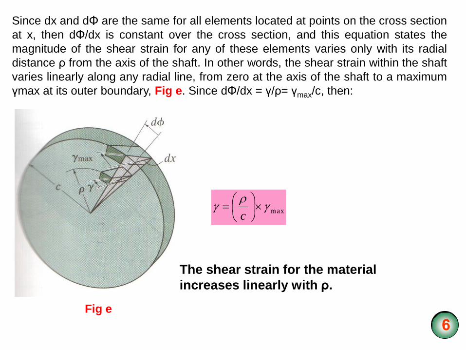
Since dx and dΦ are the same for all elements located at points on the cross section
at x, then dΦ/dx is constant over the cross section, and this equation states the
magnitude of the shear strain for any of these elements varies only with its radial
distance ρ from the axis of the shaft. In other words, the shear strain within the shaft
varies linearly along any radial line, from zero at the axis of the shaft to a maximum
γmax at its outer boundary, Fig e. Since dΦ/dx = γ/ρ= γmax/c, then:
Fig e
max
c
The shear strain for the material
increases linearly with ρ.

7
The torsion formula:
If the material is linear-elastic, then Hooke’s law applies, G and consequently
a linear variation in shear strain leads to a corresponding linear variation in shear
stress along any radial line on the cross section. We can write:
max
c
This equation expresses the shear-stress distribution as a function of the radial
position ρ of the element; in other words, it defines the stress distribution over the
cross section in terms of the geometry of the shaft. Using it, we will now apply the
condition that requires the torque produced by the stress distribution over the entire
cross section to be equivalent to the resultant internal torque T at the section,
which holds the shaft in equilibrium.
Each element of area dA, located at ρ, is subjected to a force of dAdF
The torque produced by this force is: dAdT
We therefore have for the entire cross section:
AA
dAc
dAT max

8
Since: c
maxis constant,
A
dAc
T 2max
The integral to this equation depends only on the geometry of the shaft. It
represents the polar moment of inertia of the shaft’s cross sectional area computed
about the shaft’s longitudinal axis. We will symbolise its value as J, and therefore
the above equation can be written in a more compact form, namely,
J
cT max
Where: max = the maximum shear stress in the shaft, which occurs at the outer
surface.
T= the resultant internal torque acting at the cross section. Its value is
determined from the method of sections and the equation of
moment equilibrium applied about the shaft’s longitudinal axis.
J = the polar moment of inertia of the cross-sectional area.
c = the outer radius of the shaft.

9
The shear stress at the intermediate distance ρ can be determined from a similar
equation:
J
T
“Torsion formula”
Solid shaft: 4
2cJ
Tabular shaft: If a shaft has a tabular cross section, with inner radius ci and
outer radius co, then the polar moment of inertia can be determined by
subtracting J for a shaft of radius ci from that determined for a shaft of radius
co. The result is:
44
02
iccJ

10
Solution:

11
Solution:
44
02
iccJ o = Outer
i = Inner

12
Angle of twist:
Occasionally the design of a shaft depends on restricting the amount of rotation or
twist that may occur when the shaft is subjected to a torque.
T(x)
Angle of twist:
dx
GxJ
xTL
0
Here:
Φ = the angle of twist of one end of the
shaft with respect to the other end,
measured in radians.
T(x) = the internal torque at the arbitrary
position x, found from the method of
sections and the equation of moment
equilibrium applied about the shaft’s axis.
J(x) = the shaft’s polar moment of inertia
expressed as a function of position x.
G = the shear modulus of elasticity for the
material.

13
Constant torque and cross-sectional area:
Usually in engineering practice the material is homogeneous so that G is constant.
Also, the shaft’s cross-sectional area and the applied torque are constant along the
length of the shaft.
In this case:
T(x) =T
J(x) = J
GJ
LT
.
.
If the shaft is subjected to several different torques, or the cross-sectional area or
shear modulus changes abruptly from one region of the shaft to the next then the
angle of twist from one end of the shaft with respect to the other is then found from
the vector addition of the angles of twist of each segment.
GJ
LT
.
.

14
Sign convention:
In order to apply the above equation, we must develop a sign convention for the
internal torque and the angle of twist of one end of the shaft with respect to the other
end. To do this, we will use the right-hand rule, whereby both the torque and angle
will be positive, provided the thumb is directed outward from the shaft when the
fingers curl to give the tendency for rotation.
Using the method of sections, the internal torques are found for each segment.
GJ
LT
GJ
LT
GJ
LT CDBCABDA
.
.
.
.
.
. 321/

15
Table
ΦB/A =
Solution:
BC
CD DA
+X

21
22
Stress concentration
J
cT maxThe torsion formula, can be applied to regions of a shaft having a
circular cross section that is constant or tapers slightly.
When sudden changes arise in the cross section, both the shear-stress and
shear-strain distributions in the shaft become complex and can be obtained
only by using experimental methods or possibly by a mathematical analysis
based on the theory of elasticity.
In order to eliminate the necessity for the engineer to perform a complex stress
analysis at a shaft discontinuity, the maximum shear stress can be determined
for a specified geometry using a torsional stress-concentration factor K.

23 J
cTK
..max


![Mechanics] MIT Materials Science and Engineering - Mechanics of Materials (Fall 1999)](https://img.dokumen.tips/doc/110x75/552532ce5503462a6f8b4744/mechanics-mit-materials-science-and-engineering-mechanics-of-materials-fall-1999.jpg)
