Utviklingstrekk innen fiberoptisk telekom teknologi –løsninger for verdensomspennende internettforbindelser
Steinar Bjørnstad CTO TransPacket/[email protected] Institute of Telematics Norwegian University of Science and Technology
Optical Telecom networks
The ultimate capacity across land and sea –Efficient utilization required
TRANSPACKET
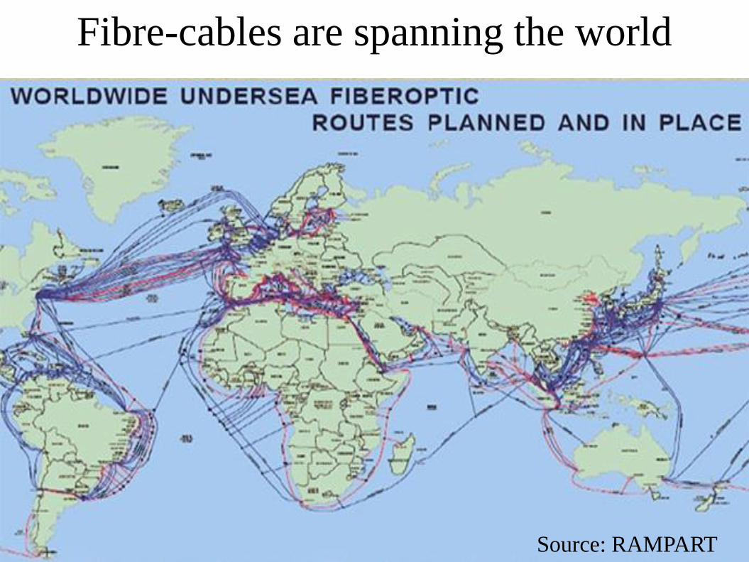
Fibre-cables are spanning the world
Source: RAMPART
Outline
● Utilizing the fibre: Transmission performance race
● How much capacity is actually needed?
● Utilizing available capacity: Optical networking
● Software defined optical networks?
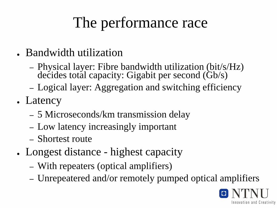
The performance race
● Bandwidth utilization
– Physical layer: Fibre bandwidth utilization (bit/s/Hz) decides total capacity: Gigabit per second (Gb/s)
– Logical layer: Aggregation and switching efficiency
● Latency
– 5 Microseconds/km transmission delay
– Low latency increasingly important
– Shortest route
● Longest distance - highest capacity
– With repeaters (optical amplifiers)
– Unrepeatered and/or remotely pumped optical amplifiers
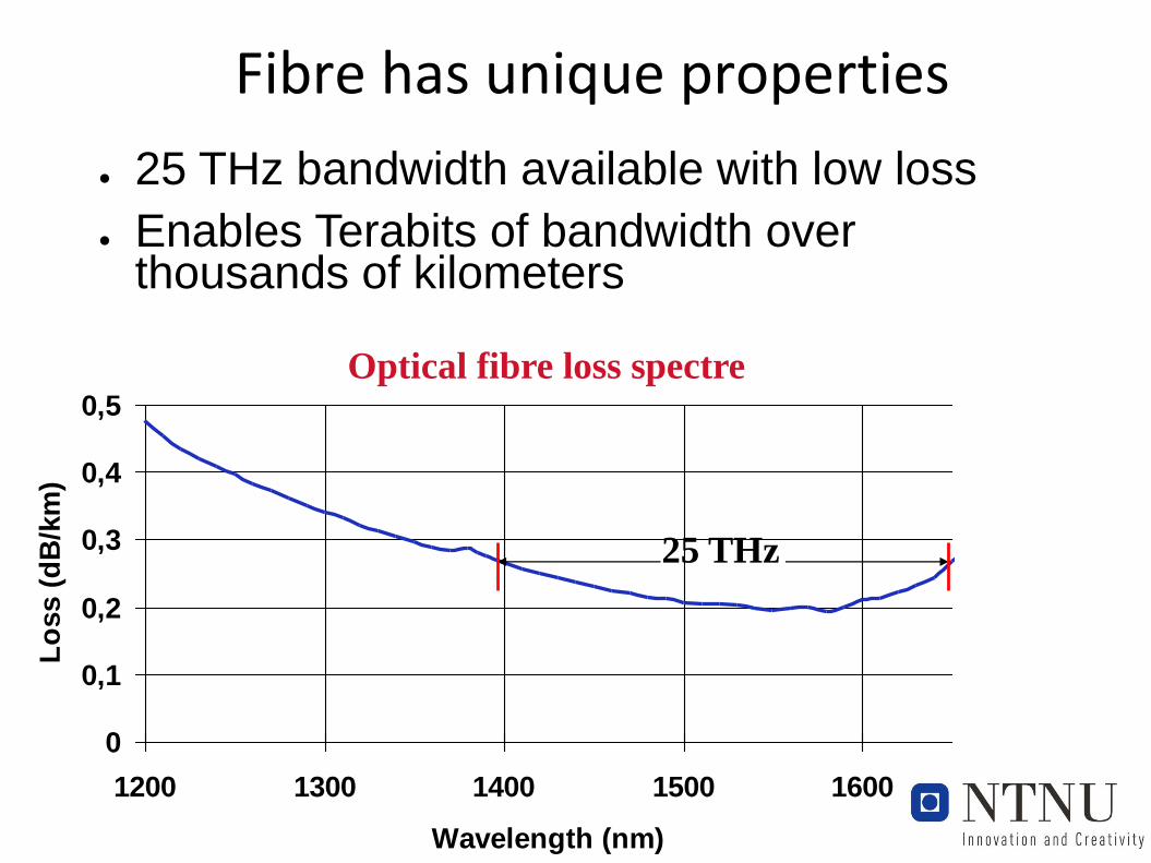
Fibre has unique properties
0
0,1
0,2
0,3
0,4
0,5
1200 1300 1400 1500 1600
Wavelength (nm)
Lo
ss (
dB
/km
)
25 THz
Optical fibre loss spectre
● 25 THz bandwidth available with low loss
● Enables Terabits of bandwidth over thousands of kilometers
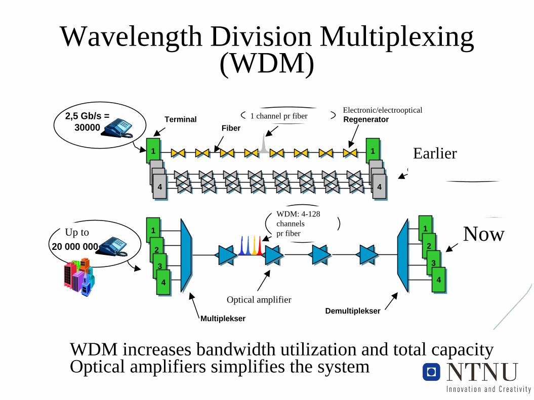
Wavelength Division Multiplexing(WDM)
11 11
11 1111 1144 44
11
22
33
44
11
22
33
44
Tidligere utbygging
RegeneratorTerminalFiber
Før: 1 kanal pr fiber
Optisk forsterker
MultiplekserDemultiplekser
2,5 Gb/s =
30000
Opptil
20 000 000
WDM:
4-128 kanaler
pr fiberNåværende
utbygging
Wavelength Division Multiplexing
(WDM), mangedobler kapasitet i fiber
Electronic/electrooptical
Now
Optical amplifier
WDM: 4-128
channels
pr fiber
1 channel pr fiber
Up to
Earlier
WDM increases bandwidth utilization and total capacityOptical amplifiers simplifies the system
Trends in WDM transmission
● Increasing bitrate in each WDM channel
● Increasing spectrum efficiency (more bits per optical Hz)
● Currently in new systems: 100 Gb/s in each channel
● Modulation format is key
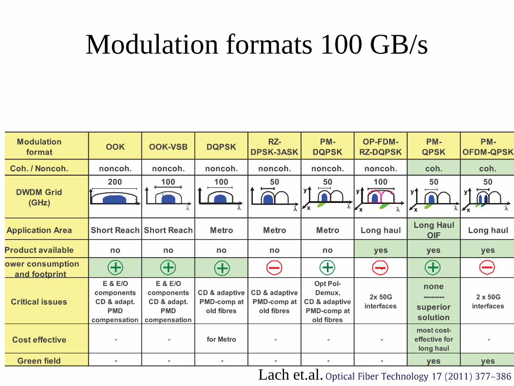
Modulation formats 100 GB/s
Lach et.al.
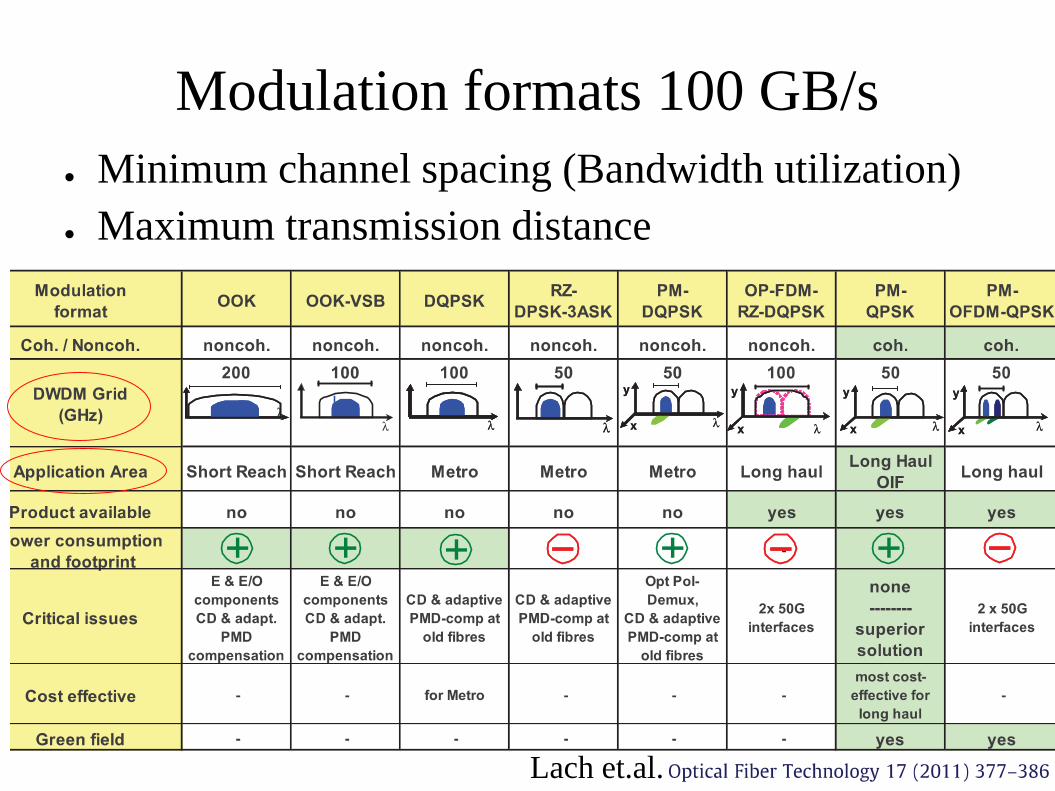
Modulation formats 100 GB/s
● Minimum channel spacing (Bandwidth utilization)
● Maximum transmission distance
Lach et.al.
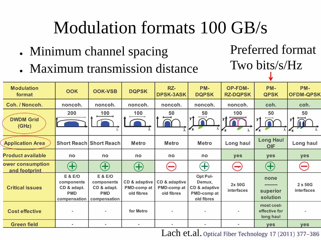
Modulation formats 100 GB/s
● Minimum channel spacing
● Maximum transmission distance
Lach et.al.
Preferred format
Two bits/s/Hz
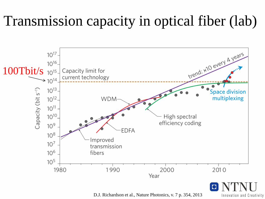
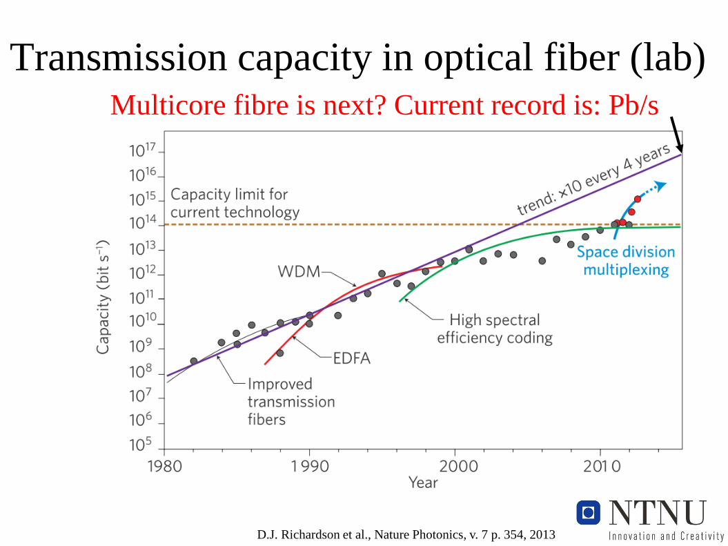
Transmission capacity in optical fiber (lab)
D.J. Richardson et al., Nature Photonics, v. 7 p. 354, 2013
100Tbit/s
Transmission capacity in optical fiber (lab)
D.J. Richardson et al., Nature Photonics, v. 7 p. 354, 2013
Multicore fibre is next? Current record is: Pb/s
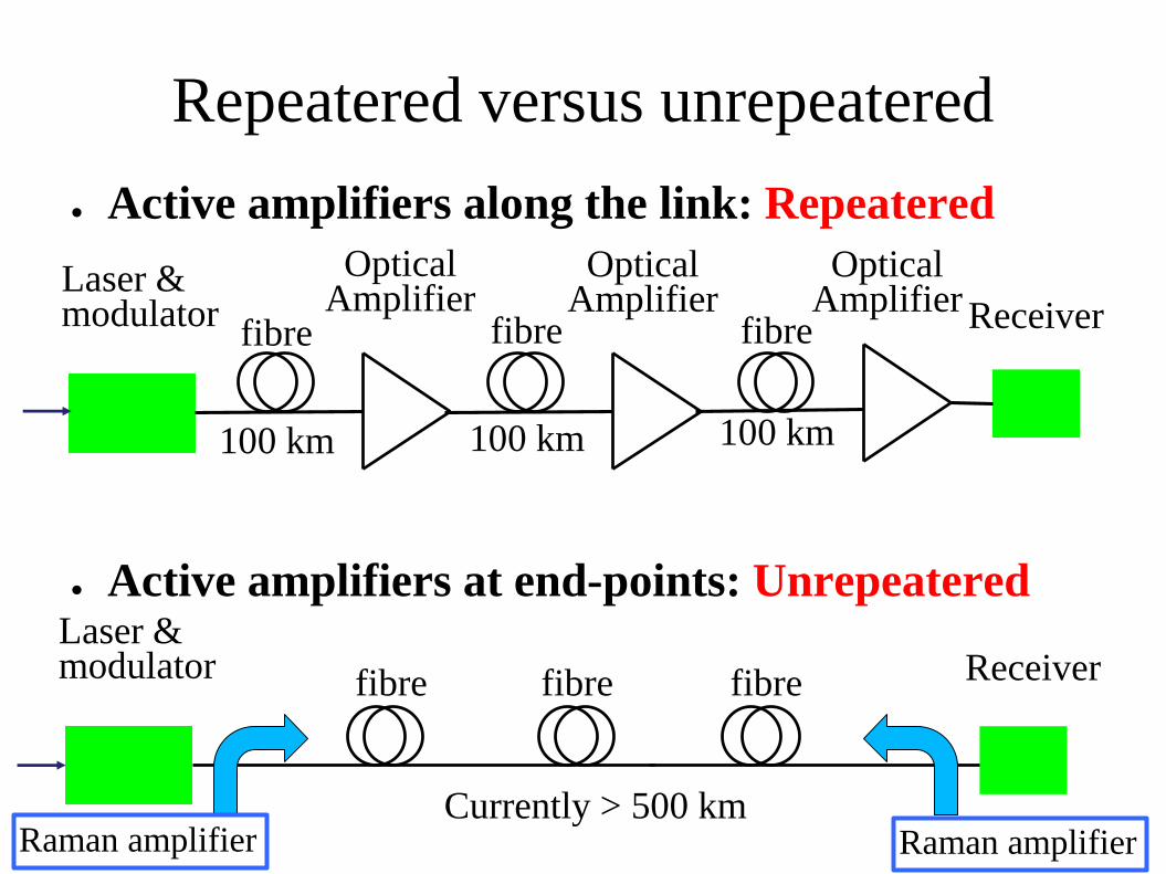
Repeatered versus unrepeatered
● Active amplifiers along the link: Repeatered
● Active amplifiers at end-points: Unrepeatered
ReceiverLaser & modulator fibrefibre fibre
Receiverfibre
Laser & modulator
OpticalAmplifier
OpticalAmplifier
fibre fibre
Raman amplifier Raman amplifier
100 km 100 km 100 km
Currently > 500 km
OpticalAmplifier
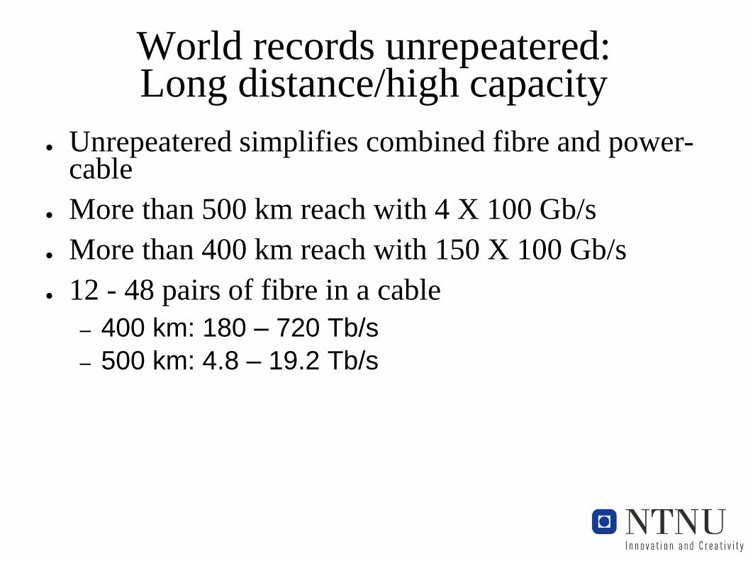
World records unrepeatered: Long distance/high capacity
● Unrepeatered simplifies combined fibre and power-cable
● More than 500 km reach with 4 X 100 Gb/s
● More than 400 km reach with 150 X 100 Gb/s
● 12 - 48 pairs of fibre in a cable
– 400 km: 180 – 720 Tb/s
– 500 km: 4.8 – 19.2 Tb/s
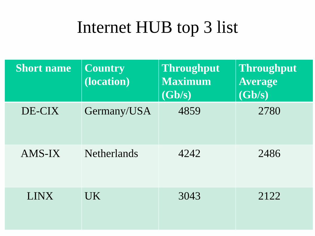
Internet HUB top 3 list
Short name Country
(location)
Throughput
Maximum
(Gb/s)
Throughput
Average
(Gb/s)
DE-CIX Germany/USA 4859 2780
AMS-IX Netherlands 4242 2486
LINX UK 3043 2122
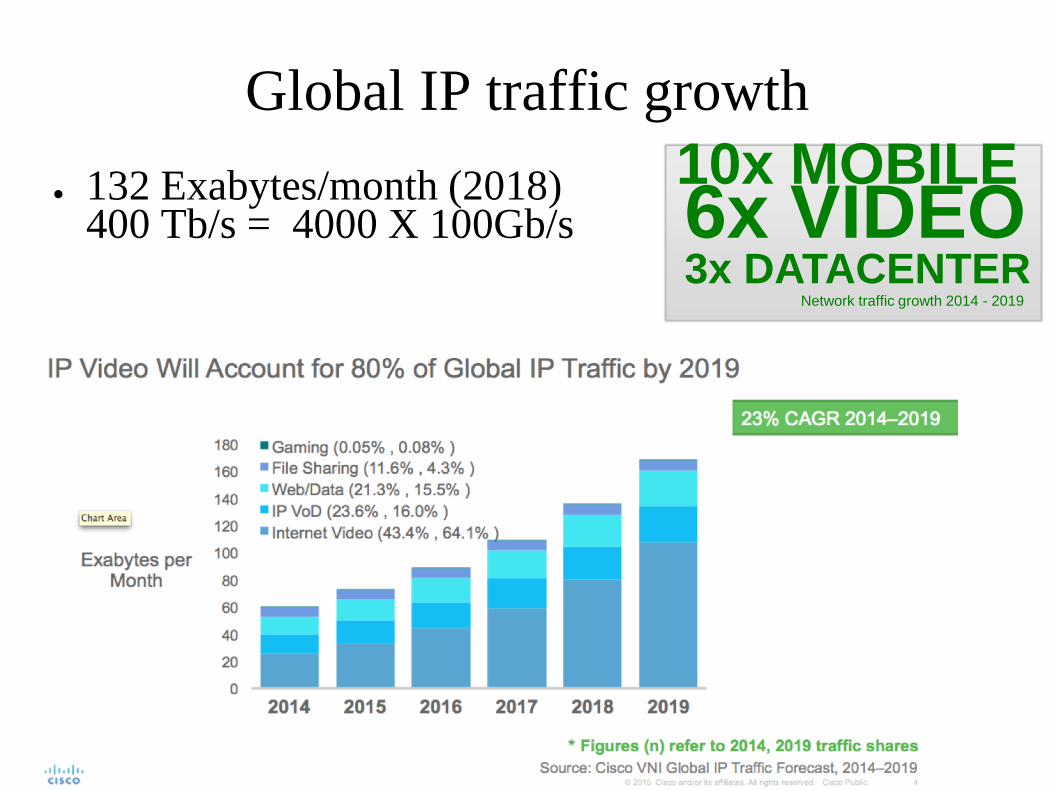
Global IP traffic growth
● 132 Exabytes/month (2018) 400 Tb/s = 4000 X 100Gb/s
10x MOBILE6x VIDEO3x DATACENTER
Network traffic growth 2014 - 2019
Market drivers optical networks
● Fibre to the Home (FTTH)
– Video applications (E.g. Netflix)
● Mobile networks
– Increased density of mobile base stations
– Fibre to the base-station
● Datacenter communication
– Between datacenters
– Connecting the datacenter to Internet
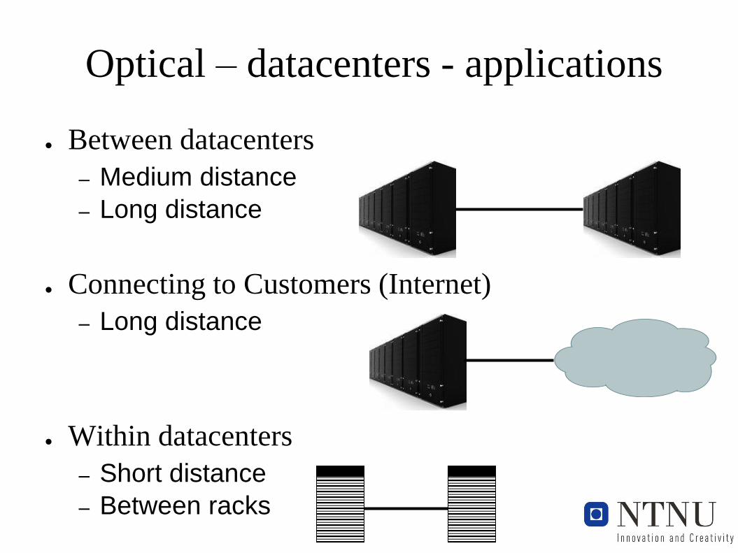
Optical – datacenters - applications
● Between datacenters
– Medium distance
– Long distance
● Connecting to Customers (Internet)
– Long distance
● Within datacenters
– Short distance
– Between racks
Optical networkingSwitching at the optical layer:
Utilizing available transmission capacity
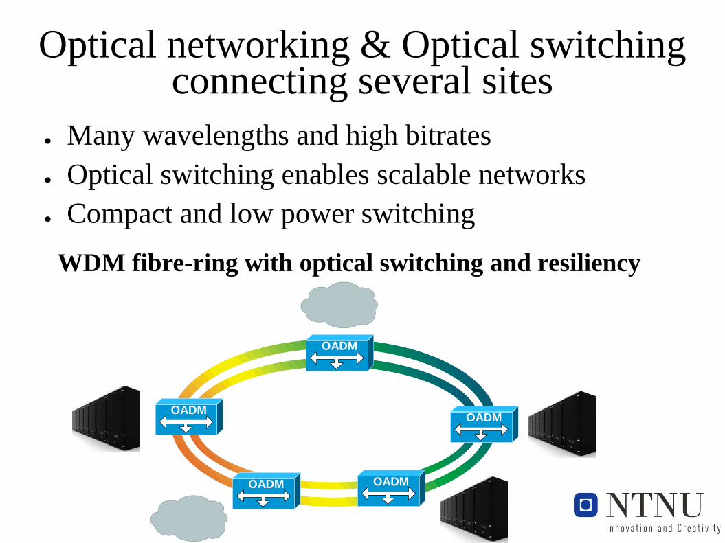
Optical networking & Optical switchingconnecting several sites
● Many wavelengths and high bitrates
● Optical switching enables scalable networks
● Compact and low power switching
OADMOADM
OADM
OADMOADM
WDM fibre-ring with optical switching and resiliency
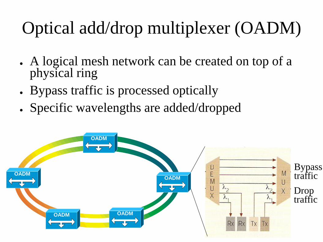
Optical add/drop multiplexer (OADM)
● A logical mesh network can be created on top of a physical ring
● Bypass traffic is processed optically
● Specific wavelengths are added/dropped
OADMOADM
OADM
OADMOADM
Bypass traffic
Drop traffic
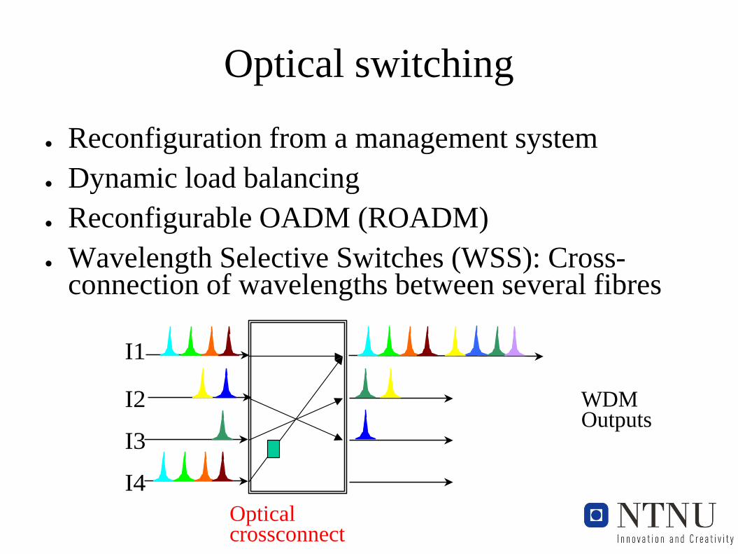
Optical switching
● Reconfiguration from a management system
● Dynamic load balancing
● Reconfigurable OADM (ROADM)
● Wavelength Selective Switches (WSS): Cross-connection of wavelengths between several fibres
Optisk krysskopler
Bølgelengde
Konverter
I1
I2
I3
I4
U1
U2
U3
U4
Optical crossconnect
WDMOutputs

What is next?
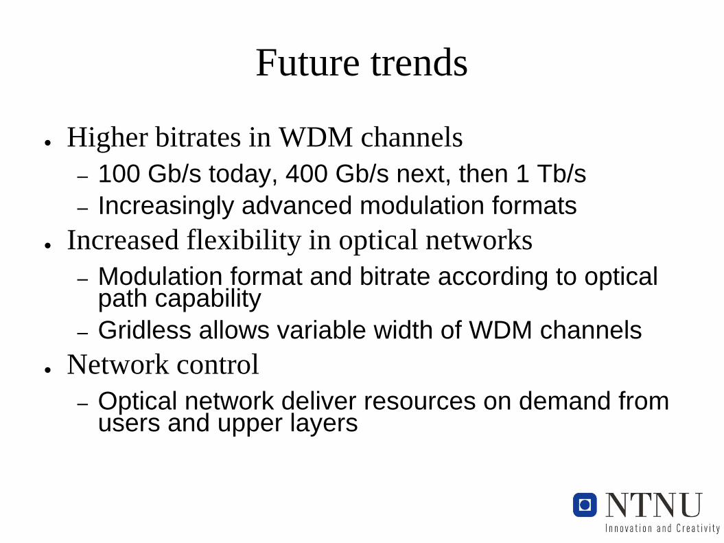
Future trends
● Higher bitrates in WDM channels
– 100 Gb/s today, 400 Gb/s next, then 1 Tb/s
– Increasingly advanced modulation formats
● Increased flexibility in optical networks
– Modulation format and bitrate according to optical path capability
– Gridless allows variable width of WDM channels
● Network control
– Optical network deliver resources on demand from users and upper layers
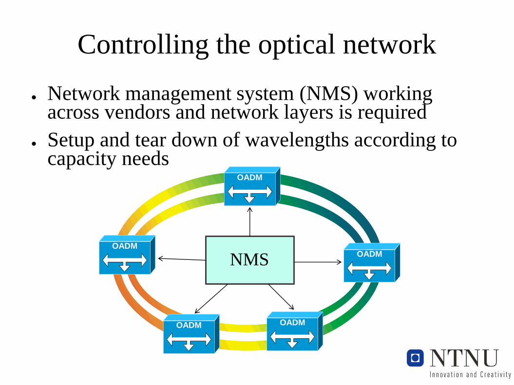
Controlling the optical network
● Network management system (NMS) working across vendors and network layers is required
● Setup and tear down of wavelengths according to capacity needs
OADMOADM
OADM
OADMOADM
NMS
Controlling across network layers
● Applications triggers resource usage on servers
● Server communication triggers network capacity needs
● IP- routers requires capacity from the optical network
● Optical network must deliver resources on demand from upper layers
Controlling across network layers
● Applications triggers resource usage on servers
● Server communication triggers network capacity needs
● IP- routers requires capacity from the optical network
● Optical network must deliver resources on demand from upper layers
Software defined networks (SDN)?
SDN goals
● Centralized control of network resources
● Control across network layers
● Control independent of equipment vendor
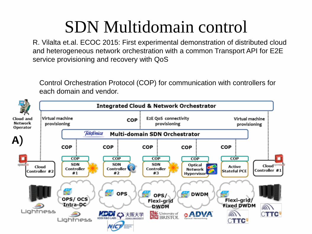
SDN Multidomain control
introduced two QoS classes (Fig.1D) in the COP
call definition (Fig.1C, trafficParams). Each QoS
class defines a certain packet loss rate (PLR) for
OPS domains, and a certain OSNR for OCS
domains, for a given bandwidth request. The
SDN orchestrator will translate the high level QoS
classes into the necessary parameters in the
calls sent to the different SDN controllers. Fig.2A
shows the message exchange between the
different involved computing and network
elements in order to jointly provide
interconnected VMs with QoS. The provisioning
of the VMs is requested to each responsible
cloud controller, while the VM interconnection is
requested to the SDN orchestrator with an E2E
call (ID: 1) including a QoS class. The SDN
orchestrator computes the E2E path and
requests the necessary calls (IDs: 10, 11, 12, 13)
to the different SDN Controllers. Fig.2B shows
the wireshark captures at the integrated cloud
and network orchestrator and at the SDN
orchestrator.
Per-domain / E2E service recovery with QoS
Fig.3A shows three conducted experiments for
QoS recovery: in an OPS domain (scenario A), in
an OCS domain (scenarios B, C) and finally E2E
QoS recovery (scenario D).
Per-domain QoS recovery through adaptive route
control in the OPS network. Fig. 3B shows the
experimental setup of the OPS domain in NICT
premises in Japan. The OPS nodes used are
optical packet and circuit integrated nodes4,
including one SOA-based 4 × 4 optical packet
switch (4 × 4 OPS). In the control plane, an OF-
based SDN controller is used to control the OPS
nodes. Four OPS nodes with optical packet
counters are used, including OF agents and OPS
transmitters and receivers. The OF agent
periodically reads and provides to SDN controller
the optical packet count information that is
measured. In this use case, two E2E transport
connections are setup involving the OPS domain,
flow1 with a packet occupancy rate of 10% and
flow2 with a packet occupancy rate of 2%. In this
case, the PLR for flow1 measured by a tester is
around 4%. When we increase the packet
occupancy rate of flow2 from 2% to 6%, the
optical packet counter of OPS node 4 reaches the
pre-defined threshold indicating packet
congestion. Fig. 3C shows the measured packet
counts of Node 4. With the increase of the packet
occupancy rate, packet count at OPS node 4 is
finally smaller than 17000, corresponding to the
pre-defined packet count threshold. The OF
agent attached to OPS node 4 detects packet
congestion and sends an alarm message to the
SDN controller. The SDN controller receives the
alarm and then issues the route adaption for the
switching table of node 2, aiming at improving the
PLR. After the route control, the obtained PLR for
flow1 measured by the traffic tester is reduced
from around 4% to 0.1%. Route adaptation is
announced to SDN orchestrator by means of
COP notification mechanism (using websocket).
QoS recovery in an OCS domain. For same BER
performance, the required OSNR value will relax
when a signal with a lower order modulation
format is used5. Fig.3E shows the tested OSNR
vs. BER curve for our 28Gbaud PM-QPSK and
PM-16QAM transmitters. QPSK requires an
OSNR value less than that of 16QAM about 9dB
at HD-FEC threshold (3.8E-3).
Moreover, OSNR monitoring of a circuit flow can
detect the OSNR degradation for optical links.
The receiver-side error-vector-magnitude (EVM)
based OSNR monitor provides in-band OSNR
monitoring without deploying new hardware6.
With monitoring information, the COP can
Fig. 1: A) Proposed LIGHTNESS-STRAUSS scenario; B) Abstracted network/cloud scenario; C) Call example, D) QoS classes
A)
B)
C)D)
Fig. 2: A) VM connectivity provisioning workflow; B) Wireshark capture.
A) B)
Ecoc 2015 - ID: 1061
R. Vilalta et.al. ECOC 2015: First experimental demonstration of distributed cloud
and heterogeneous network orchestration with a common Transport API for E2E
service provisioning and recovery with QoS
Control Orchestration Protocol (COP) for communication with controllers for
each domain and vendor.
Summary
● Optical Fibre enables ultimate capacity – ahead of current transport needs
● Capacity and maximum distance without repeaters increases steadily
● Control across vendors and protocol layers: Is Software Defined Networks (SDN) the solution?
● Capacity utilization is the key – achieving cost efficient networks
Recommended