March 2017 2222--11992211--11CC--EENN
Upflow/ Horizontal Left/Right, DownflowTwo Stage CondensingGas Fired FurnaceUUppffllooww,, CCoonnvveerrttiibbllee ttooHHoorriizzoonnttaall RRiigghhtt oorrHHoorriizzoonnttaall LLeeffttS9V2B040U3PSBAS9V2B060U3PSBAS9V2B060U4PSBAS9V2B080U3PSBAS9V2B080U4PSBAS9V2C080U5PSBAS9V2C100U4PSBAS9V2C100U5PSBAS9V2D120U5PSBA
DDoowwnnffllooww OOnnllyyS9V2B040D3PSBAS9V2B060D3PSBAS9V2B080D3PSBAS9V2B080D4PSBAS9V2C100D4PSBAS9V2C100D5PSBAS9V2D120D5PSBA
NNoottee:: Graphics in this document are for representationonly. Actual model may differ in appearance.
Product Data

2 22-1921-1C-EN
General Features
NNAATTUURRAALL GGAASS MMOODDEELLSS
Central Heating furnace designs are certified by the American Gas Association for both naturaland L.P. gas. Limit setting and rating data were established and approved under standard ratingconditions using American National Standards Institute standards.
SSAAFFEE OOPPEERRAATTIIOONN
The Integrated System Control is a solid state device which continuously monitors for presenceof flame when the system is in the heating mode of operation. Dual solenoid combination gasvalve and regulator provide additional safety.
QQUUIICCKK HHEEAATTIINNGG
Durable, cycle tested, heavy gauge ttuubbuullaarr ssttaaiinnlleessss sstteeeell pprriimmaarryy hheeaatt eexxcchhaannggeerr quicklytransfers heat to provide warm conditioned air to the structure. LLooww eenneerrggyy ppoowweerr vveennttbblloowweerr,, to increase efficiency and provide a positive discharge of gas fumes to the outside.
BBUURRNNEERRSS
Multiport Inshot burners will give years of quiet and efficient service. All models can beconverted to LL..PP.. ggaass with LP conversion kit.
IINNTTEEGGRRAATTEEDD SSYYSSTTEEMM CCOONNTTRROOLL
Exclusively designed operational program provides total control of furnace limit sensors,blowers, gas valve, flame control and includes self diagnostics for ease of service. Also containsdry contacts for EAC and HUM.
EENNEERRGGYY EEFFFFIICCIIEENNTT OOPPEERRAATTIIOONN
Furnace is certified by the manufacturer to leak 1% or less of nominal air conditioning CFMdelivered when pressurized to .5" water column with all inlets, outlets, and drains sealed.
AAIIRR DDEELLIIVVEERRYY
The variable speed blower motor has sufficient airflow for most heating and coolingrequirements and will switch from heating to cooling speeds on demand from room thermostat.
SSEECCOONNDDAARRYY HHEEAATT EEXXCCHHAANNGGEERR
The S-Series furnace has a special type 29- 4C™ stainless steel secondary heat exchanger toreclaim heat from flue gases which would normally be lost.
SSTTYYLLIINNGG
HHeeaavvyy ggaauuggee sstteeeell aanndd ""wwrraapp--aarroouunndd"" ccaabbiinneett ccoonnssttrruuccttiioonn is used in the cabinet with baked-on enamel finish for strength and beauty. Every orientation has at least two venting options.There are no knockouts on cabinet.
FFEEAATTUURREESS AANNDD GGEENNEERRAALL OOPPEERRAATTIIOONN
The S-Series furnace utilizes a Silicon Nitride Hot Surface Ignition system, which eliminates thewaste of a constant burning pilot. The integrated system control lights the main burners upon ademand for heat from the room thermostat. Complete front service access.
a. Low energy power venter
b. Vent proving pressure switches.
22-1921-1C-EN 3
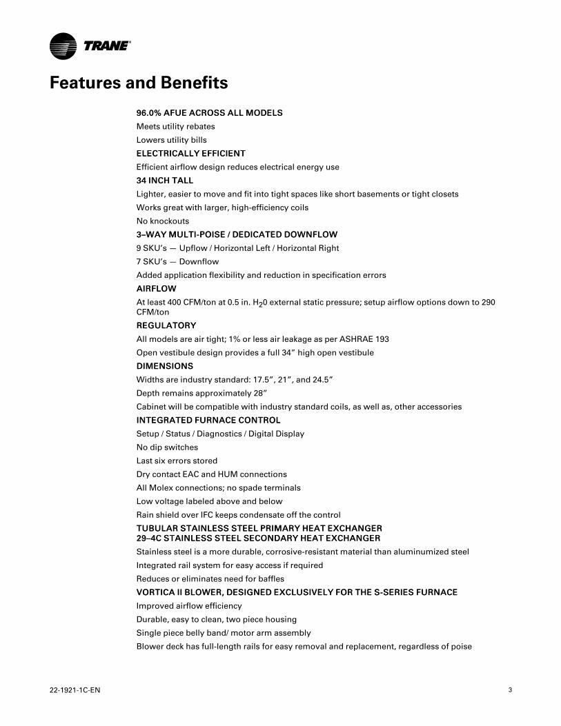
Features and Benefits
9966..00%% AAFFUUEE AACCRROOSSSS AALLLL MMOODDEELLSS
Meets utility rebates
Lowers utility bills
EELLEECCTTRRIICCAALLLLYY EEFFFFIICCIIEENNTT
Efficient airflow design reduces electrical energy use
3344 IINNCCHH TTAALLLL
Lighter, easier to move and fit into tight spaces like short basements or tight closets
Works great with larger, high-efficiency coils
No knockouts
33––WWAAYY MMUULLTTII--PPOOIISSEE // DDEEDDIICCAATTEEDD DDOOWWNNFFLLOOWW
9 SKU’s — Upflow / Horizontal Left / Horizontal Right
7 SKU’s — Downflow
Added application flexibility and reduction in specification errors
AAIIRRFFLLOOWW
At least 400 CFM/ton at 0.5 in. H20 external static pressure; setup airflow options down to 290CFM/ton
RREEGGUULLAATTOORRYY
All models are air tight; 1% or less air leakage as per ASHRAE 193
Open vestibule design provides a full 34” high open vestibule
DDIIMMEENNSSIIOONNSS
Widths are industry standard: 17.5”, 21”, and 24.5”
Depth remains approximately 28”
Cabinet will be compatible with industry standard coils, as well as, other accessories
IINNTTEEGGRRAATTEEDD FFUURRNNAACCEE CCOONNTTRROOLL
Setup / Status / Diagnostics / Digital Display
No dip switches
Last six errors stored
Dry contact EAC and HUM connections
All Molex connections; no spade terminals
Low voltage labeled above and below
Rain shield over IFC keeps condensate off the control
TTUUBBUULLAARR SSTTAAIINNLLEESSSS SSTTEEEELL PPRRIIMMAARRYY HHEEAATT EEXXCCHHAANNGGEERR2299––44CC SSTTAAIINNLLEESSSS SSTTEEEELL SSEECCOONNDDAARRYY HHEEAATT EEXXCCHHAANNGGEERR
Stainless steel is a more durable, corrosive-resistant material than aluminumized steel
Integrated rail system for easy access if required
Reduces or eliminates need for baffles
VVOORRTTIICCAA IIII BBLLOOWWEERR,, DDEESSIIGGNNEEDD EEXXCCLLUUSSIIVVEELLYY FFOORR TTHHEE SS--SSEERRIIEESS FFUURRNNAACCEE
Improved airflow efficiency
Durable, easy to clean, two piece housing
Single piece belly band/ motor arm assembly
Blower deck has full-length rails for easy removal and replacement, regardless of poise

4 22-1921-1C-EN
TTHHRREEEE––WWAAYY MMUULLTTII--PPOOIISSEE ((UUPPFFLLOOWW,, HHOORRIIZZOONNTTAALL LLEEFFTT AANNDD RRIIGGHHTT)) PPLLUUSS DDEEDDIICCAATTEEDDDDOOWWNNFFLLOOWW
Easier to specify
Shipped ready to install (no kits required)
Every model has at least two venting options
When in horizontal, trap extends only about 2”
Barbed fitting on trap at hose connection and on cabinet transition for hose has barbed fittingand clamps at both ends for leak resistance.
Vent table improvements including longer vent lengths; 2” pipe can be used up to 100K
FFeeaattuurreess aanndd BBeenneeffiittss

22-1921-1C-EN 5
AccessoriesTable 1. Accessories
Model Number Description Use with
BAYHANG Horizontal Hanging Kit All Upflow Furnaces
BAYVENT200B Sidewall Vent Termination Kit All Furnaces
BAYVENTCN200B Sidewall Vent Termination Kit (Canada —CPVC)
All Furnaces
BAYAIR30AVENTA Concentric Vent Kit All Furnaces
BAYAIR30CNVENT Concentric Vent Kit (Canada — CPVC) All Furnaces
BAYREDUCE Reducing Coupling (CPVC) All Furnaces
BAYLIFTB Dual Return Kit (B size extension) B Cabinet Upflow Furnaces
BAYLIFTC Dual Return Kit (C size extension) C Cabinet Upflow Furnaces
BAYLIFTD Dual Return Kit (D size extension) D Cabinet Upflow Furnaces
BAYBASE205 Downflow Subbase All Downflow FurnacesBAYFLTR206 Filter Access Door Kit (Downflow only) All Upflow Furnaces
BAYSLF1165AA (a) 1” SlimFit Box with MERV 4 Filter All Upflow Furnaces
BAYFLTR203 Horizontal Filter Kit B Cabinet Furnaces in Downflow/Horizontal
BAYFLTR204 Horizontal Filter Kit C Cabinet Furnaces in Downflow/Horizontal
BAYFLTR205 Horizontal Filter Kit D Cabinet Furnaces in Downflow/Horizontal
BAYLPSS400A LP Conversion Kit with Stainless Steel Burners All Furnaces
BAYMFGH200A Manufactured/Mobile Housing Kit All Furnaces(a) Airflow greater than 1600 CFM requires dual returns

6 22-1921-1C-EN
Product Specification
MODEL S9V2B040U3PSBA (a) S9V2B060U3PSBA(a) S9V2B060U4PSBA(a) S9V2B080U3PSBA(a)
TYPE Upflow/Horizontal Upflow/Horizontal Upflow/Horizontal Upflow / Horizontal
RATINGS (b)
1st Stage Input BTUH (ICS) 26,000 39,000 39,000 52,000
1st Stage Capacity BTUH 25,220 37,830 37,830 50,440
2nd Stage Input BTUH 40,000 60,000 60,000 80,000
2nd Stage Capacity BTUH (ICS) (c) (d) 38,800 58,200 58,200 77,600
1st Stage Temp. Rise (Min.-Max.) 25 - 55 25 - 55 25 - 55 30 - 60
2nd Stage Temp. Rise (Min.-Max.) 30 - 60 35 - 65 35 - 65 40 - 70
AFUE (%) (c)(d) 96.0 96.0 96.0 96.0
BLOWER DRIVE DIRECT DIRECT DIRECT DIRECT
Diameter —Width (In.) 11 X 8 11 X 8 11 X 8 11 X 8
No. Used 1 1 1 1
Speeds (No.) Variable Variable Variable Variable
CFM vs. in. w.g. See Fan PerformanceTable
See Fan PerformanceTable
See Fan PerformanceTable
See Fan PerformanceTable
Motor HP 1/2 1/2 3/4 1/2
RPM Variable Variable Variable Variable
Volts/Ph/Hz 120 / 1 / 60 120 / 1 / 60 120 / 1 / 60 120 / 1 / 60
FLA 5.7 5.7 8.0 5.7
COMBUSTION FAN— Type Centrifugal Centrifugal Centrifugal Centrifugal
Drive — No. Speeds Direct - 2 Direct - 2 Direct - 2 Direct - 2
Motor HP — RPM 3300/2600 3300/2600 3300/2600 3300/2600
Volts/Ph/Hz 120 / 1 / 60 120 / 1 / 60 120 / 1 / 60 120 / 1 / 60
FLA 0.66 0.66 0.66 0.66
FILTER— Furnished? No No No No
Type recommended High Velocity High Velocity High Velocity High Velocity
Hi Vel. (No.-Size-Thk.) 1 — 16x25 — 1 in. 1 — 16x25 — 1 in. 1 — 16x25 — 1 in. 1 — 16x25 — 1 in.VENT PIPE DIAMETER—Min (in.)(e) (f) 2 Round 2 Round 2 Round 2 Round
HEAT EXCHANGER
Type — Fired 409 Stainless Steel 409 Stainless Steel 409 Stainless Steel 409 Stainless Steel
— Unfired 29–4C Stainless Steel 29–4C Stainless Steel 29–4C Stainless Steel 29–4C Stainless Steel
Gauge (Fired) 20 20 20 20
ORIFICES—Main
Nat. Gas Qty.— Drill Size 2- 45 3 - 45 3 - 45 4 - 45
LP Gas Qty.— Drill Size 2- 56 3 - 56 3 - 56 4 - 56
GAS VALVE Redundant - Two Stage Redundant - Two Stage Redundant - Two Stage Redundant - Two Stage
PILOT SAFETY DEVICE
Type 120 V SiNi Igniter 120 V SiNi Igniter 120 V SiNi Igniter 120 V SiNi Igniter
BURNERS— Type Multiport Inshot Multiport Inshot Multiport Inshot Multiport Inshot
Number 2 3 3 4
POWER CONN. — V/Ph/Hz (g) 120 / 1 / 60 120 / 1 / 60 120 / 1 / 60 120 / 1 / 60
Ampacity (In Amps) 7.9 7.9 10.8 7.9
22-1921-1C-EN 7
MODEL S9V2B040U3PSBA (a) S9V2B060U3PSBA(a) S9V2B060U4PSBA(a) S9V2B080U3PSBA(a)
Max. Overcurrent Protection (Amps) 15 15 15 15
PIPE CONN. SIZE (in.) 1/2 1/2 1/2 1/2
DIMENSIONS H x W x D H x W x D H x W x D H x W x D
Uncrated (In.) 34 x 17-1/2 x 28–3/4 34 x 17-1/2 x 28–3/4 34 x 17-1/2 x 28–3/4 34 x 17-1/2 x 28–3/4
Crated (In.) 35-1/2 x 19-1/2 x 30-7/8 35-1/2 x 19-1/2 x 30-7/8 35-1/2 x 19-1/2 x 30-7/8 35-1/2 x 19-1/2 x 30-7/8
WEIGHT
Shipping (Lbs.)/Net (Lbs.) 122/114 127/119 130/122 132/124
(a) Meets Energy Star(b) For U.S. applications, above input ratings (BTUH) are up to 2,000 feet, derate 4% per 1,000 feet for elevations above 2,000 feet above sea level. For
Canadian applications, above input ratings (BTUH) are up to 4,500 feet, derate 4% per 1,000 feet for elevations above 4,500 feet above sea level.(c) Central Furnace heating designs are certified to ANSI Z21.47 / CSA 2.3 — latest edition.(d) Based on U.S. government standard tests.(e) Refer to the Vent Length Table in the Installer's Guide.(f) All S9V2 furnace models have a vent outlet diameter that equals 2 in.(g) The above wiring specifications are in accordance with National Electrical Code; however, installations must comply with local codes.
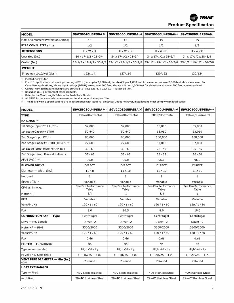
MODEL S9V2B080U4PSBA (a) S9V2C080U5PSBA(a) S9V2C100U4PSBA(a) S9V2C100U5PSBA(a)
TYPE Upflow/Horizontal Upflow/Horizontal Upflow/Horizontal Upflow / Horizontal
RATINGS (b)
1st Stage Input BTUH (ICS) 52,000 52,000 65,000 65,000
1st Stage Capacity BTUH 50,440 50,440 63,050 63,050
2nd Stage Input BTUH 80,000 80,000 100,000 100,000
2nd Stage Capacity BTUH (ICS) (c) (d) 77,600 77,600 97,000 97,000
1st Stage Temp. Rise (Min.-Max.) 30 - 60 30 - 60 25 - 55 25 - 55
2nd Stage Temp. Rise (Min.-Max.) 35 - 65 35 - 65 35 - 65 30 - 60
AFUE (%) (c)(d) 96.0 96.0 96.0 96.0
BLOWER DRIVE DIRECT DIRECT DIRECT DIRECT
Diameter —Width (In.) 11 X 8 11 X 10 11 X 10 11 X 10
No. Used 1 1 1 1
Speeds (No.) Variable Variable Variable Variable
CFM vs. in. w.g. See Fan PerformanceTable
See Fan PerformanceTable
See Fan PerformanceTable
See Fan PerformanceTable
Motor HP 3/4 1 3/4 1
RPM Variable Variable Variable Variable
Volts/Ph/Hz 120 / 1 / 60 120 / 1 / 60 120 / 1 / 60 120 / 1 / 60
FLA 8.0 10.5 8.0 10.5
COMBUSTION FAN— Type Centrifugal Centrifugal Centrifugal Centrifugal
Drive — No. Speeds Direct - 2 Direct - 2 Direct - 2 Direct - 2
Motor HP — RPM 3300/2600 3300/2600 3300/2600 3300/2600
Volts/Ph/Hz 120 / 1 / 60 120 / 1 / 60 120 / 1 / 60 120 / 1 / 60
FLA 0.66 0.66 0.66 0.66
FILTER— Furnished? No No No No
Type recommended High Velocity High Velocity High Velocity High Velocity
Hi Vel. (No.-Size-Thk.) 1 — 16x25 — 1 in. 1 — 20x25 — 1 in. 1 — 20x25 — 1 in. 1 — 20x25 — 1 in.VENT PIPE DIAMETER—Min (in.)(e) (f) 2 Round 2 Round 2 Round 2 Round
HEAT EXCHANGER
Type — Fired 409 Stainless Steel 409 Stainless Steel 409 Stainless Steel 409 Stainless Steel
— Unfired 29–4C Stainless Steel 29–4C Stainless Steel 29–4C Stainless Steel 29–4C Stainless Steel
PPrroodduucctt SSppeecciiffiiccaattiioonn

8 22-1921-1C-EN
MODEL S9V2B080U4PSBA (a) S9V2C080U5PSBA(a) S9V2C100U4PSBA(a) S9V2C100U5PSBA(a)
Gauge (Fired) 20 20 20 20
ORIFICES—Main
Nat. Gas Qty.— Drill Size 4 - 45 4 - 45 5 - 45 5 - 45
LP Gas Qty.— Drill Size 4- 56 4- 56 5- 56 5- 56
GAS VALVE Redundant - Two Stage Redundant - Two Stage Redundant - Two Stage Redundant - Two Stage
PILOT SAFETY DEVICE
Type 120 V SiNi Igniter 120 V SiNi Igniter 120 V SiNi Igniter 120 V SiNi Igniter
BURNERS— Type Multiport Inshot Multiport Inshot Multiport Inshot Multiport Inshot
Number 4 4 5 5
POWER CONN. — V/Ph/Hz (g) 120 / 1 / 60 120 / 1 / 60 120 / 1 / 60 120 / 1 / 60
Ampacity (In Amps) 10.8 13.9 10.8 13.9
Max. Overcurrent Protection (Amps) 15 15 15 15
PIPE CONN. SIZE (in.) 1/2 1/2 1/2 1/2
DIMENSIONS H x W x D H xW x D H xW x D H xW x D
Uncrated (In.) 34 x 17-1/2 x 28–3/4 34 x 21 x 28–3/4 34 x 21 x 28–3/4 34 x 21 x 28–3/4
Crated (In.) 35-1/2 x 19-1/2 x 30-7/8 35-1/2 x 23 x 30-7/8 35-1/2 x 23 x 30-7/8 35-1/2 x 23 x 30-7/8
WEIGHT
Shipping (Lbs.)/Net (Lbs.) 135/127 149/139 154/144 155/145
(a) Meets Energy Star(b) For U.S. applications, above input ratings (BTUH) are up to 2,000 feet, derate 4% per 1,000 feet for elevations above 2,000 feet above sea level. For
Canadian applications, above input ratings (BTUH) are up to 4,500 feet, derate 4% per 1,000 feet for elevations above 4,500 feet above sea level.(c) Central Furnace heating designs are certified to ANSI Z21.47 / CSA 2.3 — latest edition.(d) Based on U.S. government standard tests.(e) Refer to the Vent Length Table in the Installer's Guide.(f) All S9V2 furnace models have a vent outlet diameter that equals 2 in.(g) The above wiring specifications are in accordance with National Electrical Code; however, installations must comply with local codes.
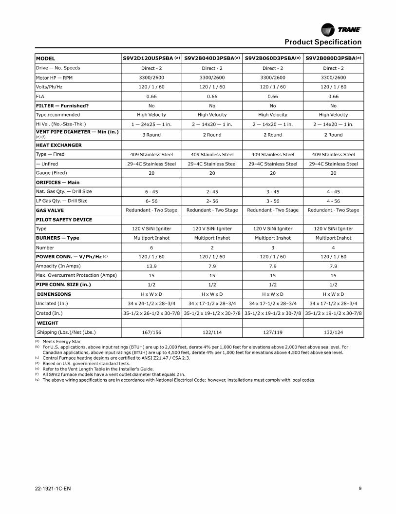
MODEL S9V2D120U5PSBA (a) S9V2B040D3PSBA(a) S9V2B060D3PSBA(a) S9V2B080D3PSBA(a)
TYPE Upflow/Horizontal Downflow Downflow Downflow
RATINGS (b)
1st Stage Input BTUH (ICS) 78,000 26,000 39,000 52,000
1st Stage Capacity BTUH 75,660 25,220 37,830 50,440
2nd Stage Input BTUH 120,000 40,000 60,000 80,000
2nd Stage Capacity BTUH (ICS) (c) (d) 116,400 38,800 58,200 77,600
1st Stage Temp. Rise (Min.-Max.) 35-65 25 - 55 25 - 55 30 - 60
2nd Stage Temp. Rise (Min.-Max.) 40-70 30 - 60 35 - 65 40 - 70
AFUE (%) (c)(d) 96.0 96.0 96.0 96.0
BLOWER DRIVE DIRECT DIRECT DIRECT DIRECT
Diameter —Width (In.) 11 X 10 11 X 8 11 X 8 11 X 8
No. Used 1 1 1 1
Speeds (No.) Variable Variable Variable Variable
CFM vs. in. w.g. See Fan PerformanceTable
See Fan PerformanceTable
See Fan PerformanceTable
See Fan PerformanceTable
Motor HP 1 1/2 1/2 1/2
RPM Variable Variable Variable Variable
Volts/Ph/Hz 120 / 1 / 60 120 / 1 / 60 120 / 1 / 60 120 / 1 / 60
FLA 10.5 5.7 5.7 5.7
COMBUSTION FAN— Type Centrifugal Centrifugal Centrifugal Centrifugal
PPrroodduucctt SSppeecciiffiiccaattiioonn
22-1921-1C-EN 9
MODEL S9V2D120U5PSBA (a) S9V2B040D3PSBA(a) S9V2B060D3PSBA(a) S9V2B080D3PSBA(a)
Drive — No. Speeds Direct - 2 Direct - 2 Direct - 2 Direct - 2
Motor HP — RPM 3300/2600 3300/2600 3300/2600 3300/2600
Volts/Ph/Hz 120 / 1 / 60 120 / 1 / 60 120 / 1 / 60 120 / 1 / 60
FLA 0.66 0.66 0.66 0.66
FILTER— Furnished? No No No No
Type recommended High Velocity High Velocity High Velocity High Velocity
Hi Vel. (No.-Size-Thk.) 1 — 24x25 — 1 in. 2 — 14x20 — 1 in. 2 — 14x20 — 1 in. 2 — 14x20 — 1 in.VENT PIPE DIAMETER—Min (in.)(e) (f) 3 Round 2 Round 2 Round 2 Round
HEAT EXCHANGER
Type — Fired 409 Stainless Steel 409 Stainless Steel 409 Stainless Steel 409 Stainless Steel
— Unfired 29–4C Stainless Steel 29–4C Stainless Steel 29–4C Stainless Steel 29–4C Stainless Steel
Gauge (Fired) 20 20 20 20
ORIFICES—Main
Nat. Gas Qty.— Drill Size 6 - 45 2- 45 3 - 45 4 - 45
LP Gas Qty.— Drill Size 6- 56 2- 56 3 - 56 4 - 56
GAS VALVE Redundant - Two Stage Redundant - Two Stage Redundant - Two Stage Redundant - Two Stage
PILOT SAFETY DEVICE
Type 120 V SiNi Igniter 120 V SiNi Igniter 120 V SiNi Igniter 120 V SiNi Igniter
BURNERS— Type Multiport Inshot Multiport Inshot Multiport Inshot Multiport Inshot
Number 6 2 3 4
POWER CONN. — V/Ph/Hz (g) 120 / 1 / 60 120 / 1 / 60 120 / 1 / 60 120 / 1 / 60
Ampacity (In Amps) 13.9 7.9 7.9 7.9
Max. Overcurrent Protection (Amps) 15 15 15 15
PIPE CONN. SIZE (in.) 1/2 1/2 1/2 1/2
DIMENSIONS H x W x D H x W x D H x W x D H x W x D
Uncrated (In.) 34 x 24-1/2 x 28–3/4 34 x 17-1/2 x 28–3/4 34 x 17-1/2 x 28–3/4 34 x 17-1/2 x 28–3/4
Crated (In.) 35-1/2 x 26-1/2 x 30-7/8 35-1/2 x 19-1/2 x 30-7/8 35-1/2 x 19-1/2 x 30-7/8 35-1/2 x 19-1/2 x 30-7/8
WEIGHT
Shipping (Lbs.)/Net (Lbs.) 167/156 122/114 127/119 132/124
(a) Meets Energy Star(b) For U.S. applications, above input ratings (BTUH) are up to 2,000 feet, derate 4% per 1,000 feet for elevations above 2,000 feet above sea level. For
Canadian applications, above input ratings (BTUH) are up to 4,500 feet, derate 4% per 1,000 feet for elevations above 4,500 feet above sea level.(c) Central Furnace heating designs are certified to ANSI Z21.47 / CSA 2.3.(d) Based on U.S. government standard tests.(e) Refer to the Vent Length Table in the Installer's Guide.(f) All S9V2 furnace models have a vent outlet diameter that equals 2 in.(g) The above wiring specifications are in accordance with National Electrical Code; however, installations must comply with local codes.
PPrroodduucctt SSppeecciiffiiccaattiioonn

10 22-1921-1C-EN
MODEL S9V2B080D4PSBA (a) S9V2C100D4PSBA(a) S9V2C100D5PSBA(a) S9V2D120D5PSBA(a)
TYPE Downflow Downflow Downflow Downflow
RATINGS (b)
1st Stage Input BTUH (ICS) 52,000 65,000 65,000 78,000
1st Stage Capacity BTUH 50,440 63,050 63,050 75,660
2nd Stage Input BTUH 80,000 100,000 100,000 120,000
2nd Stage Capacity BTUH (ICS) (c) (d) 77,600 97,000 97,000 116,400
1st Stage Temp. Rise (Min.-Max.) 30 - 60 25 - 55 25 - 55 35-65
2nd Stage Temp. Rise (Min.-Max.) 35 - 65 35 - 65 30 - 60 40-70
AFUE (%) (c)(d) 96.0 96.0 96.0 96.0
BLOWER DRIVE DIRECT DIRECT DIRECT DIRECT
Diameter —Width (In.) 11 X 8 11 X 10 11 X 10 11 X 10
No. Used 1 1 1 1
Speeds (No.) Variable Variable Variable Variable
CFM vs. in. w.g. See Fan PerformanceTable
See Fan PerformanceTable
See Fan PerformanceTable
See Fan PerformanceTable
Motor HP 3/4 3/4 1 1
RPM Variable Variable Variable Variable
Volts/Ph/Hz 120 / 1 / 60 120 / 1 / 60 120 / 1 / 60 120 / 1 / 60
FLA 8.0 8.0 10.5 10.5
COMBUSTION FAN— Type Centrifugal Centrifugal Centrifugal Centrifugal
Drive — No. Speeds Direct - 2 Direct - 2 Direct - 2 Direct - 2
Motor HP — RPM 3300/2600 3300/2600 3300/2600 3300/2600
Volts/Ph/Hz 120 / 1 / 60 120 / 1 / 60 120 / 1 / 60 120 / 1 / 60
FLA 0.66 0.66 0.66 0.66
FILTER— Furnished? No No No No
Type recommended High Velocity High Velocity High Velocity High Velocity
Hi Vel. (No.-Size-Thk.) 2 — 14x20 — 1 in. 2 — 16x20 — 1 in. 2 — 16x20 — 1 in. 2 — 16x20 — 1 in.VENT PIPE DIAMETER—Min (in.)(e) (f) 2 Round 2 Round 2 Round 3 Round
HEAT EXCHANGER
Type — Fired 409 Stainless Steel 409 Stainless Steel 409 Stainless Steel 409 Stainless Steel
— Unfired 29–4C Stainless Steel 29–4C Stainless Steel 29–4C Stainless Steel 29–4C Stainless Steel
Gauge (Fired) 20 20 20 20
ORIFICES—Main
Nat. Gas Qty.— Drill Size 4 - 45 5 - 45 5 - 45 6 - 45
LP Gas Qty.— Drill Size 4- 56 5- 56 5- 56 6- 56
GAS VALVE Redundant - Two Stage Redundant - Two Stage Redundant - Two Stage Redundant - Two Stage
PILOT SAFETY DEVICE
Type 120 V SiNi Igniter 120 V SiNi Igniter 120 V SiNi Igniter 120 V SiNi Igniter
BURNERS— Type Multiport Inshot Multiport Inshot Multiport Inshot Multiport Inshot
Number 4 5 5 6
POWER CONN. — V/Ph/Hz (g) 120 / 1 / 60 120 / 1 / 60 120 / 1 / 60 120 / 1 / 60
Ampacity (In Amps) 10.8 10.8 13.9 13.9
Max. Overcurrent Protection (Amps) 15 15 15 15
PIPE CONN. SIZE (in.) 1/2 1/2 1/2 1/2
PPrroodduucctt SSppeecciiffiiccaattiioonn

22-1921-1C-EN 11
MODEL S9V2B080D4PSBA (a) S9V2C100D4PSBA(a) S9V2C100D5PSBA(a) S9V2D120D5PSBA(a)
DIMENSIONS H x W x D H xW x D H xW x D H xW x D
Uncrated (In.) 34 x 17-1/2 x 28–3/4 34 x 21 x 28–3/4 34 x 21 x 28–3/4 34 x 24-1/2 x 28–3/4
Crated (In.) 35-1/2 x 19-1/2 x 30-7/8 35-1/2 x 23 x 30-7/8 35-1/2 x 23 x 30-7/8 35-1/2 x 26-1/2 x 30-7/8
WEIGHT
Shipping (Lbs.)/Net (Lbs.) 135/127 154/144 155/145 167/156
(a) Meets Energy Star(b) For U.S. applications, above input ratings (BTUH) are up to 2,000 feet, derate 4% per 1,000 feet for elevations above 2,000 feet above sea level. For
Canadian applications, above input ratings (BTUH) are up to 4,500 feet, derate 4% per 1,000 feet for elevations above 4,500 feet above sea level.(c) Central Furnace heating designs are certified to ANSI Z21.47 / CSA 2.3.(d) Based on U.S. government standard tests.(e) Refer to the Vent Length Table in the Installer's Guide.(f) All S9V2 furnace models have a vent outlet diameter that equals 2 in.(g) The above wiring specifications are in accordance with National Electrical Code; however, installations must comply with local codes.
PPrroodduucctt SSppeecciiffiiccaattiioonn
12 22-1921-1C-EN
Heating and Cooling Airflow Tables
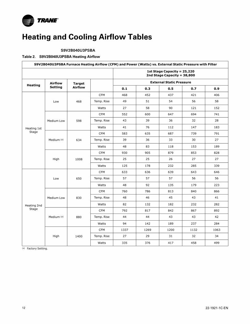
SS99VV22BB004400UU33PPSSBBAA
Table 2. S9V2B040U3PSBA Heating Airflow
S9V2B040U3PSBA Furnace Heating Airflow (CFM) and Power (Watts) vs. External Static Pressure with Filter
1st Stage Capacity = 25,2202nd Stage Capacity = 38,800
Heating AirflowSetting
TargetAirflow
External Static Pressure
0.1 0.3 0.5 0.7 0.9
Heating 1stStage
Low 468
CFM 468 452 437 421 406
Temp. Rise 49 51 54 56 58
Watts 27 58 90 121 152
Medium Low 598
CFM 552 600 647 694 741
Temp. Rise 43 39 36 32 28
Watts 41 76 112 147 183
Medium (a) 634
CFM 583 635 687 739 791
Temp. Rise 39 36 33 30 27
Watts 48 83 118 153 189
High 1008
CFM 930 905 879 853 828
Temp. Rise 25 25 26 27 27
Watts 125 178 232 285 339
Heating 2ndStage
Low 650
CFM 633 636 639 643 646
Temp. Rise 57 57 57 56 56
Watts 48 92 135 179 223
Medium Low 830
CFM 760 786 813 840 866
Temp. Rise 48 46 45 43 41
Watts 82 132 182 232 282
Medium (a) 880
CFM 792 817 842 867 892
Temp. Rise 44 44 43 43 42
Watts 94 142 189 237 284
High 1400
CFM 1337 1269 1200 1132 1063
Temp. Rise 27 29 31 32 34
Watts 335 376 417 458 499
(a) Factory Setting.

22-1921-1C-EN 13
SS99VV22BB004400DD33PPSSBBAA
Table 3. S9V2B040D3PSBA Heating Airflow
S9V2B040D3PSBA Furnace Heating Airflow (CFM) and Power (Watts) vs. External Static Pressure with Filter
1st Stage Capacity = 25,2202nd Stage Capacity = 38,800
Heating AirflowSetting
TargetAirflow
External Static Pressure
0.1 0.3 0.5 0.7 0.9
Heating 1stStage
Low 468
CFM 426 430 435 439 444
Temp. Rise 54 54 53 53 52
Watts 38 79 120 161 202
Medium Low 598
CFM 543 569 595 621 647
Temp. Rise 43 41 39 37 35
Watts 66 125 184 243 303
Medium (a) 634
CFM 611 612 614 616 618
Temp. Rise 38 38 38 37 37
Watts 81 139 198 256 314
High 1008
CFM 923 918 914 909 904
Temp. Rise 25 25 25 25 26
Watts 198 284 369 455 540
Heating 2ndStage
Low 650
CFM 607 612 617 622 626
Temp. Rise 60 60 59 59 59
Watts 78 124 170 216 261
Medium Low 830
CFM 807 807 808 808 809
Temp. Rise 45 45 45 45 45
Watts 146 218 290 362 434
Medium (a) 880
CFM 871 874 878 881 885
Temp. Rise 42 42 42 41 41
Watts 182 259 336 413 489
High 1400
CFM 1307 1237 1167 1097 1028
Temp. Rise 28 30 32 33 35
Watts 492 526 560 593 627
(a) Factory Setting.
HHeeaattiinngg aanndd CCoooolliinngg AAiirrffllooww TTaabblleess

14 22-1921-1C-EN
SS99VV22BB004400UU33PPSSBBAA // SS99VV22BB004400DD33PPSSBBAA
Table 4. S9V2B040U3PSBA / S9V2B040D3PSBA Cooling Airflow
S9V2B040U3PSBA / S9V2B040D3PSBA Furnace Cooling Airflow (CFM) and Power (Watts) vs. External Static Pressurewith Filter
Cooling UnitOutdoor
AirflowSetting(CFM/ton)
External Static Pressure
0.1 0.3 0.5 0.7 0.9
Cooling 1.5 Ton
Cooling 450CFM/Ton
CFM 675 675 675 675 675
Watts 47 81 121 166 215
Cooling 420CFM/Ton
CFM 630 630 630 630 630
Watts 40 72 111 154 202
Cooling 400CFM/Ton
CFM 600 600 600 600 600
Watts 36 67 105 147 193
Cooling 370CFM/Ton
CFM 555 555 555 555 555
Watts 30 60 96 136 181
Cooling 350CFM/Ton
CFM 525 525 525 525 525
Watts 27 56 90 130 174
Cooling 330CFM/Ton
CFM 495 495 495 495 495
Watts 24 51 85 124 167
Cooling 310CFM/Ton
CFM 465 465 465 465 465
Watts 21 48 80 118 161
Cooling 290CFM/Ton
CFM 435 435 435 435 435
Watts 19 44 76 113 155
Cooling 2.0 Ton
Cooling 450CFM/Ton
CFM 900 900 900 900 900
Watts 94 137 186 240 298
Cooling 420CFM/Ton
CFM 840 840 840 840 840
Watts 79 120 166 218 273
Cooling 400CFM/Ton
CFM 800 800 800 800 800
Watts 70 109 154 204 258
Cooling 370CFM/Ton
CFM 740 740 740 740 740
Watts 58 95 138 185 236
Cooling 350CFM/Ton
CFM 700 700 700 700 700
Watts 51 86 127 173 223
Cooling 330CFM/Ton
CFM 660 660 660 660 660
Watts 44 78 118 162 211
Cooling 310CFM/Ton
CFM 620 620 620 620 620
Watts 38 71 109 152 199
Cooling 290CFM/Ton
CFM 580 580 580 580 580
Watts 33 64 101 142 188
Cooling 2.5 Ton
Cooling 450CFM/Ton
CFM 1125 1125 1125 1125 1125
Watts 167 219 278 341 408
Cooling 420CFM/Ton CFM
1050 1050 1050 1050 1050
HHeeaattiinngg aanndd CCoooolliinngg AAiirrffllooww TTaabblleess
22-1921-1C-EN 15
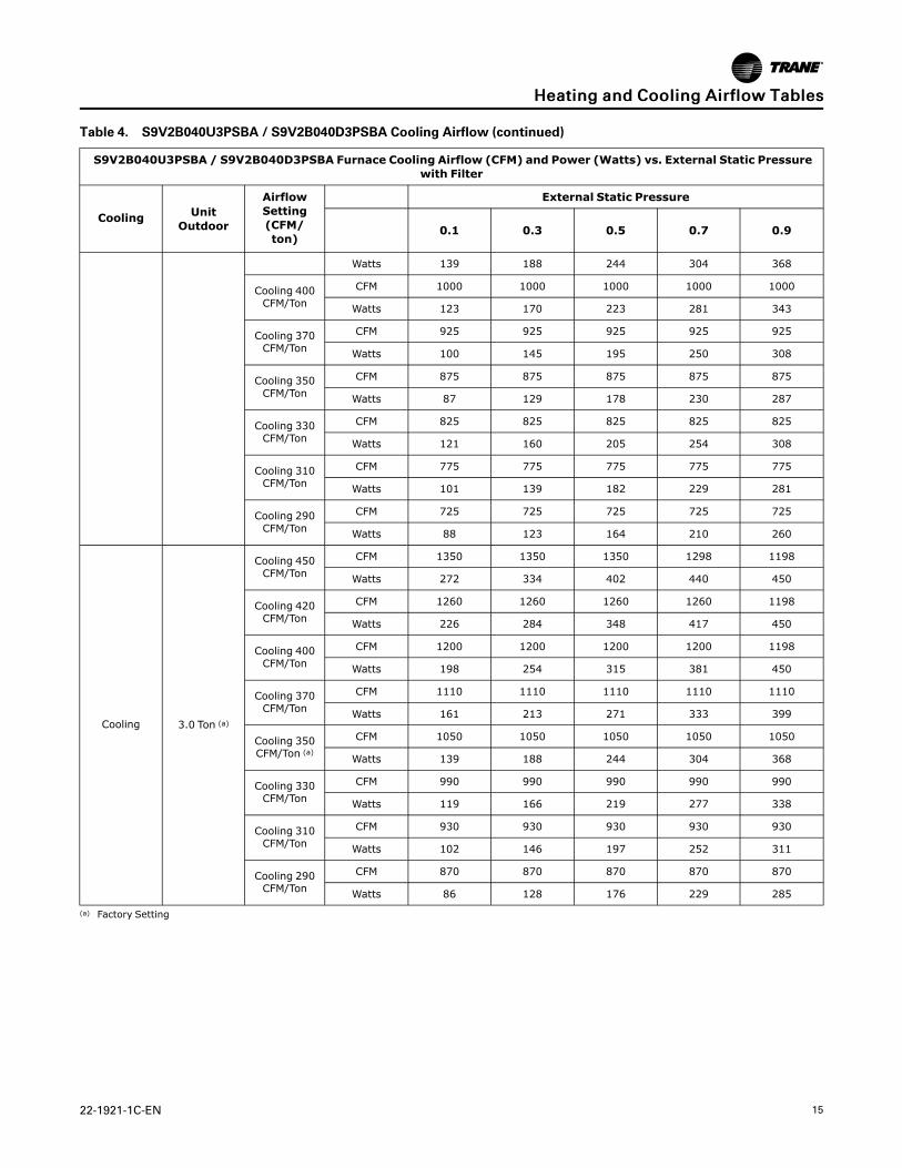
Table 4. S9V2B040U3PSBA / S9V2B040D3PSBA Cooling Airflow (continued)
S9V2B040U3PSBA / S9V2B040D3PSBA Furnace Cooling Airflow (CFM) and Power (Watts) vs. External Static Pressurewith Filter
Cooling UnitOutdoor
AirflowSetting(CFM/ton)
External Static Pressure
0.1 0.3 0.5 0.7 0.9
Watts 139 188 244 304 368
Cooling 400CFM/Ton
CFM 1000 1000 1000 1000 1000
Watts 123 170 223 281 343
Cooling 370CFM/Ton
CFM 925 925 925 925 925
Watts 100 145 195 250 308
Cooling 350CFM/Ton
CFM 875 875 875 875 875
Watts 87 129 178 230 287
Cooling 330CFM/Ton
CFM 825 825 825 825 825
Watts 121 160 205 254 308
Cooling 310CFM/Ton
CFM 775 775 775 775 775
Watts 101 139 182 229 281
Cooling 290CFM/Ton
CFM 725 725 725 725 725
Watts 88 123 164 210 260
Cooling 3.0 Ton (a)
Cooling 450CFM/Ton
CFM 1350 1350 1350 1298 1198
Watts 272 334 402 440 450
Cooling 420CFM/Ton
CFM 1260 1260 1260 1260 1198
Watts 226 284 348 417 450
Cooling 400CFM/Ton
CFM 1200 1200 1200 1200 1198
Watts 198 254 315 381 450
Cooling 370CFM/Ton
CFM 1110 1110 1110 1110 1110
Watts 161 213 271 333 399
Cooling 350CFM/Ton (a)
CFM 1050 1050 1050 1050 1050
Watts 139 188 244 304 368
Cooling 330CFM/Ton
CFM 990 990 990 990 990
Watts 119 166 219 277 338
Cooling 310CFM/Ton
CFM 930 930 930 930 930
Watts 102 146 197 252 311
Cooling 290CFM/Ton
CFM 870 870 870 870 870
Watts 86 128 176 229 285
(a) Factory Setting
HHeeaattiinngg aanndd CCoooolliinngg AAiirrffllooww TTaabblleess

16 22-1921-1C-EN
SS99VV22BB006600UU33PPSSBBAA
Table 5. S9V2B060U3PSBA Heating Airflow
S9V2B060U3PSBA Furnace Heating Airflow (CFM) and Power (Watts) vs. External Static Pressure with Filter
1st Stage Capacity = 37,8302nd Stage Capacity = 58,200
Heating AirflowSetting
TargetAirflow
External Static Pressure
0.1 0.3 0.5 0.7 0.9
Heating 1stStage
Low 632
CFM 673 675 677 679 681
Temp. Rise 52 52 52 52 52
Watts 47 83 120 156 193
Medium Low(a) 814
CFM 850 827 804 780 757
Temp. Rise 41 42 43 44 45
Watts 82 120 157 195 232
Medium 893
CFM 901 903 905 907 909
Temp. Rise 39 39 39 39 39
Watts 106 144 181 219 256
High 1153
CFM 1131 1121 1112 1102 1093
Temp. Rise 32 31 31 31 31
Watts 209 250 291 332 373
Heating 2ndStage
Low 800
CFM 850 844 838 833 827
Temp. Rise 63 63 64 64 65
Watts 75 120 165 210 255
Medium Low(a) 1030
CFM 1072 1061 1049 1038 1027
Temp. Rise 50 50 51 52 52
Watts 147 196 244 293 341
Medium 1130
CFM 1115 1127 1138 1149 1160
Temp. Rise 48 48 48 47 47
Watts 193 246 300 354 408
High 1460
CFM 1382 1336 1289 1243 1196
Temp. Rise 39 40 42 43 45
Watts 382 400 418 435 453
(a) Factory Setting.
HHeeaattiinngg aanndd CCoooolliinngg AAiirrffllooww TTaabblleess

22-1921-1C-EN 17
SS99VV22BB006600DD33PPSSBBAA
Table 6. S9V2B060D3PSBA Heating Airflow
S9V2B060D3PSBA Furnace Heating Airflow (CFM) and Power (Watts) vs. External Static Pressure with Filter
1st Stage Capacity = 37,8302nd Stage Capacity = 58,200
Heating AirflowSetting
TargetAirflow
External Static Pressure
0.1 0.3 0.5 0.7 0.9
Heating 1stStage
Low 632
CFM 701 683 664 646 627
Temp. Rise 51 52 54 55 57
Watts 33 79 125 171 217
Medium Low(a) 814
CFM 799 812 825 838 851
Temp. Rise 45 44 43 42 42
Watts 56 109 163 217 270
Medium 893
CFM 887 895 903 910 918
Temp. Rise 40 40 40 39 39
Watts 77 128 180 231 283
High 1153
CFM 1075 1087 1099 1111 1122
Temp. Rise 33 33 33 32 32
Watts 163 227 291 355 419
Heating 2ndStage
Low 800
CFM 833 825 816 808 800
Temp. Rise 64 65 66 67 67
Watts 48 109 170 231 292
Medium Low(a) 1030
CFM 987 991 995 1000 1004
Temp. Rise 55 55 55 54 54
Watts 117 109 237 298 358
Medium 1130
CFM 1054 1071 1088 1105 1122
Temp. Rise 51 50 49 48 48
Watts 165 211 256 302 348
High 1460
CFM 1336 1337 1338 1339 1340
Temp. Rise 40 40 40 40 40
Watts 375 402 429 456 483
(a) Factory Setting.
HHeeaattiinngg aanndd CCoooolliinngg AAiirrffllooww TTaabblleess

18 22-1921-1C-EN
SS99VV22BB006600UU33PPSSBBAA // SS99VV22BB006600DD33PPSSBBAA
Table 7. S9V2B060U3PSBA / S9V2B060D3PSBA Cooling Airflow
S9V2B060U3PSBA / S9V2B060D3PSBA Furnace Cooling Airflow (CFM) and Power (Watts) vs. External Static Pressurewith Filter
Cooling UnitOutdoor
AirflowSetting(CFM/ton)
External Static Pressure
0.1 0.3 0.5 0.7 0.9
Cooling 1.5 Ton
Cooling 450CFM/Ton
CFM 675 675 675 675 675
Watts 46 81 121 165 212
Cooling 420CFM/Ton
CFM 630 630 630 630 630
Watts 40 72 111 153 200
Cooling 400CFM/Ton
CFM 600 600 600 600 600
Watts 36 67 105 146 192
Cooling 370CFM/Ton
CFM 555 555 555 555 555
Watts 30 60 96 137 182
Cooling 350CFM/Ton
CFM 525 525 525 525 525
Watts 27 56 91 131 175
Cooling 330CFM/Ton
CFM 495 495 495 495 495
Watts 24 52 86 126 170
Cooling 310CFM/Ton
CFM 465 465 465 465 465
Watts 21 48 82 121 164
Cooling 290CFM/Ton
CFM 435 435 435 435 435
Watts 19 45 78 116 160
Cooling 2.0 Ton
Cooling 450CFM/Ton
CFM 900 900 900 900 900
Watts 92 135 184 236 291
Cooling 420CFM/Ton
CFM 840 840 840 840 840
Watts 78 118 164 214 267
Cooling 400CFM/Ton
CFM 800 800 800 800 800
Watts 69 108 153 201 253
Cooling 370CFM/Ton
CFM 740 740 740 740 740
Watts 57 94 136 183 232
Cooling 350CFM/Ton
CFM 700 700 700 700 700
Watts 50 86 126 171 220
Cooling 330CFM/Ton
CFM 660 660 660 660 660
Watts 44 78 117 161 208
Cooling 310CFM/Ton
CFM 620 620 620 620 620
Watts 38 71 109 151 197
Cooling 290CFM/Ton
CFM 580 580 580 580 580
Watts 33 64 101 142 187
Cooling 2.5 Ton
Cooling 450CFM/Ton
CFM 1125 1125 1125 1125 1125
Watts 164 216 273 334 399
Cooling 420CFM/Ton CFM
1050 1050 1050 1050 1050
HHeeaattiinngg aanndd CCoooolliinngg AAiirrffllooww TTaabblleess

22-1921-1C-EN 19
Table 7. S9V2B060U3PSBA / S9V2B060D3PSBA Cooling Airflow (continued)
S9V2B060U3PSBA / S9V2B060D3PSBA Furnace Cooling Airflow (CFM) and Power (Watts) vs. External Static Pressurewith Filter
Cooling UnitOutdoor
AirflowSetting(CFM/ton)
External Static Pressure
0.1 0.3 0.5 0.7 0.9
Watts 137 186 240 298 359
Cooling 400CFM/Ton
CFM 1000 1000 1000 1000 1000
Watts 121 168 220 276 335
Cooling 370CFM/Ton
CFM 925 925 925 925 925
Watts 99 143 192 245 302
Cooling 350CFM/Ton
CFM 875 875 875 875 875
Watts 86 128 175 227 281
Cooling 330CFM/Ton
CFM 825 825 825 825 825
Watts 74 115 160 209 262
Cooling 310CFM/Ton
CFM 775 775 775 775 775
Watts 64 102 146 193 244
Cooling 290CFM/Ton
CFM 725 725 725 725 725
Watts 54 91 133 178 228
Cooling 3.0 Ton (a)
Cooling 450CFM/Ton
CFM 1350 1350 1350 1296 1218
Watts 267 329 395 431 452
Cooling 420CFM/Ton
CFM 1260 1260 1260 1260 1218
Watts 222 279 342 409 452
Cooling 400CFM/Ton
CFM 1200 1200 1200 1200 1200
Watts 195 250 310 374 441
Cooling 370CFM/Ton
CFM 1110 1110 1110 1110 1110
Watts 158 210 266 327 390
Cooling 350CFM/Ton (a)
CFM 1050 1050 1050 1050 1050
Watts 137 186 240 298 359
Cooling 330CFM/Ton
CFM 990 990 990 990 990
Watts 118 164 216 272 330
Cooling 310CFM/Ton
CFM 930 930 930 930 930
Watts 100 145 194 247 304
Cooling 290CFM/Ton
CFM 870 870 870 870 870
Watts 85 127 174 225 279
(a) Factory Setting
HHeeaattiinngg aanndd CCoooolliinngg AAiirrffllooww TTaabblleess

20 22-1921-1C-EN
SS99VV22BB006600UU44PPSSBBAA
Table 8. S9V2B060U4PSBA Heating Airflow
S9V2B060U4PSBA Furnace Heating Airflow (CFM) and Power (Watts) vs. External Static Pressure with Filter
1st Stage Capacity = 37,8302nd Stage Capacity = 58,200
Heating AirflowSetting
TargetAirflow
External Static Pressure
0.1 0.3 0.5 0.7 0.9
Heating 1stStage
Low 782
CFM 765 755 745 736 726
Temp. Rise 46 47 47 48 49
Watts 75 120 166 212 258
Medium Low 861
CFM 817 812 807 802 797
Temp. Rise 43 43 44 44 44
Watts 91 140 188 237 286
Medium (a) 916
CFM 860 856 852 848 844
Temp. Rise 41 41 41 41 42
Watts 102 153 204 256 307
High 1256
CFM 1111 1109 1107 1105 1103
Temp. Rise 32 32 32 32 32
Watts 227 291 355 419 484
Heating 2ndStage
Low 990
CFM 950 945 941 936 932
Temp. Rise 56 56 57 57 58
Watts 119 171 224 277 330
Medium Low 1090
CFM 1022 1021 1020 1018 1017
Temp. Rise 52 52 52 53 53
Watts 147 202 257 312 367
Medium (a) 1160
CFM 1086 1084 1081 1079 1077
Temp. Rise 49 49 49 50 50
Watts 181 239 297 356 414
High 1590
CFM 1478 1459 1441 1422 1404
Temp. Rise 36 37 37 38 38
Watts 434 496 558 620 682
(a) Factory Setting.
HHeeaattiinngg aanndd CCoooolliinngg AAiirrffllooww TTaabblleess

22-1921-1C-EN 21
SS99VV22BB006600UU44PPSSBBAA
Table 9. S9V2B060U4PSBA Cooling Airflow
S9V2B060U4PSBA Furnace Cooling Airflow (CFM) and Power (Watts) vs. External Static Pressure with Filter
Cooling UnitOutdoor
AirflowSetting(CFM/ton)
External Static Pressure
0.1 0.3 0.5 0.7 0.9
Cooling 2.5 Ton
Cooling 450CFM/Ton
CFM 1125 1125 1125 1125 1125
Watts 154 205 261 319 381
Cooling 420CFM/Ton
CFM 1050 1050 1050 1050 1050
Watts 128 177 229 285 343
Cooling 400CFM/Ton
CFM 1000 1000 1000 1000 1000
Watts 113 159 210 264 320
Cooling 370CFM/Ton
CFM 925 925 925 925 925
Watts 93 136 184 234 288
Cooling 350CFM/Ton
CFM 875 875 875 875 875
Watts 81 122 168 217 269
Cooling 330CFM/Ton
CFM 825 825 825 825 825
Watts 70 109 153 200 251
Cooling 310CFM/Ton
CFM 775 775 775 775 775
Watts 60 97 139 185 234
Cooling 290CFM/Ton
CFM 725 725 725 725 725
Watts 51 87 127 171 219
Cooling 3.0 Ton
Cooling 450CFM/Ton
CFM 1350 1350 1350 1350 1350
Watts 250 312 377 445 515
Cooling 420CFM/Ton
CFM 1260 1260 1260 1260 1260
Watts 208 265 326 390 457
Cooling 400CFM/Ton
CFM 1200 1200 1200 1200 1200
Watts 182 237 296 357 422
Cooling 370CFM/Ton
CFM 1110 1110 1110 1110 1110
Watts 148 199 254 312 373
Cooling 350CFM/Ton
CFM 1050 1050 1050 1050 1050
Watts 128 177 229 285 343
Cooling 330CFM/Ton
CFM 990 990 990 990 990
Watts 110 156 206 260 316
Cooling 310CFM/Ton
CFM 930 930 930 930 930
Watts 94 138 185 236 290
Cooling 290CFM/Ton
CFM 870 870 870 870 870
Watts 80 121 166 215 267
Cooling 3.5 Ton
Cooling 450CFM/Ton
CFM 1575 1575 1575 1575 1575
Watts 382 453 528 606 686
Cooling 420CFM/Ton
CFM 1470 1470 1470 1470 1470
Watts 316 382 453 526 602
HHeeaattiinngg aanndd CCoooolliinngg AAiirrffllooww TTaabblleess

22 22-1921-1C-EN
Table 9. S9V2B060U4PSBA Cooling Airflow (continued)
S9V2B060U4PSBA Furnace Cooling Airflow (CFM) and Power (Watts) vs. External Static Pressure with Filter
Cooling UnitOutdoor
AirflowSetting(CFM/ton)
External Static Pressure
0.1 0.3 0.5 0.7 0.9
Cooling 400CFM/Ton
CFM 1400 1400 1400 1400 1400
Watts 276 340 407 477 550
Cooling 370CFM/Ton
CFM 1295 1295 1295 1295 1295
Watts 224 283 345 411 479
Cooling 350CFM/Ton
CFM 1225 1225 1225 1225 1225
Watts 193 249 308 371 436
Cooling 330CFM/Ton
CFM 1155 1155 1155 1155 1155
Watts 165 218 274 334 397
Cooling 310CFM/Ton
CFM 1085 1085 1085 1085 1085
Watts 140 190 243 301 360
Cooling 290CFM/Ton
CFM 1015 1015 1015 1015 1015
Watts 118 165 216 270 327
Cooling 4.0 Ton (a)
Cooling 450CFM/Ton
CFM 1800 1800 1730 1670 1600
Watts 554 636 656 686 708
Cooling 420CFM/Ton
CFM 1680 1680 1680 1670 1600
Watts 457 533 613 686 708
Cooling 400CFM/Ton
CFM 1600 1600 1600 1600 1600
Watts 399 472 548 626 708
Cooling 370CFM/Ton
CFM 1480 1480 1480 1480 1480
Watts 322 389 459 533 609
Cooling 350CFM/Ton (a)
CFM 1400 1400 1400 1400 1400
Watts 276 340 407 477 550
Cooling 330CFM/Ton
CFM 1320 1320 1320 1320 1320
Watts 236 296 359 426 495
Cooling 310CFM/Ton
CFM 1240 1240 1240 1240 1240
Watts 199 256 316 379 445
Cooling 290CFM/Ton
CFM 1160 1160 1160 1160 1160
Watts 167 220 277 337 399
(a) Factory Setting
HHeeaattiinngg aanndd CCoooolliinngg AAiirrffllooww TTaabblleess

22-1921-1C-EN 23
SS99VV22BB008800UU33PPSSBBAA
Table 10. S9V2B080U3PSBA Heating Airflow
S9V2B080U3PSBA Furnace Heating Airflow (CFM) and Power (Watts) vs. External Static Pressure with Filter
1st Stage Capacity = 50,4402nd Stage Capacity = 77,600
Heating AirflowSetting
TargetAirflow
External Static Pressure
0.1 0.3 0.5 0.7 0.9
Heating 1stStage
Low 948
CFM 1070 1030 990 950 910
Temp. Rise 45 45 46 46 46
Watts 120 162 203 245 286
Medium Low 1051
CFM 1109 1061 1013 965 917
Temp. Rise 42 44 46 47 49
Watts 143 197 252 307 361
Medium (a) 1090
CFM 1188 1125 1062 998 935
Temp. Rise 40 42 43 45 47
Watts 154 215 276 336 397
High 1168
CFM 1230 1212 1193 1174 1156
Temp. Rise 38 39 39 40 41
Watts 194 246 297 349 401
Heating 2ndStage
Low 1200
CFM 1331 1293 1256 1218 1172
Temp. Rise 55 56 57 58 61
Watts 221 277 333 388 436
Medium Low 1330
CFM 1436 1388 1340 1263 1172
Temp. Rise 50 52 54 56 61
Watts 287 347 407 421 436
Medium (a) 1380
CFM 1380 1380 1338 1263 1172
Temp. Rise 52 52 53 56 61
Watts 283 351 396 421 436
High 1480
CFM 1460 1400 1338 1263 1172
Temp. Rise 49 51 53 56 61
Watts 329 363 396 421 436
(a) Factory Setting.
HHeeaattiinngg aanndd CCoooolliinngg AAiirrffllooww TTaabblleess
24 22-1921-1C-EN
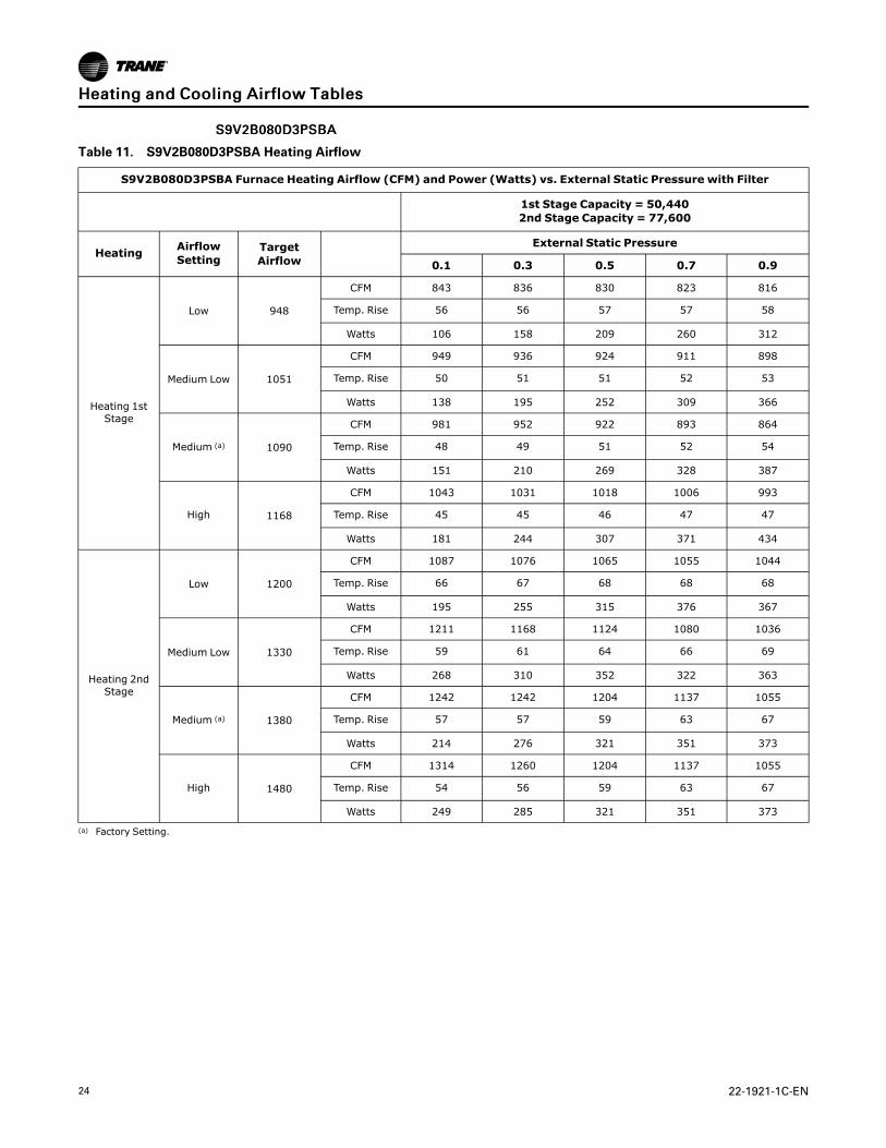
SS99VV22BB008800DD33PPSSBBAA
Table 11. S9V2B080D3PSBA Heating Airflow
S9V2B080D3PSBA Furnace Heating Airflow (CFM) and Power (Watts) vs. External Static Pressure with Filter
1st Stage Capacity = 50,4402nd Stage Capacity = 77,600
Heating AirflowSetting
TargetAirflow
External Static Pressure
0.1 0.3 0.5 0.7 0.9
Heating 1stStage
Low 948
CFM 843 836 830 823 816
Temp. Rise 56 56 57 57 58
Watts 106 158 209 260 312
Medium Low 1051
CFM 949 936 924 911 898
Temp. Rise 50 51 51 52 53
Watts 138 195 252 309 366
Medium (a) 1090
CFM 981 952 922 893 864
Temp. Rise 48 49 51 52 54
Watts 151 210 269 328 387
High 1168
CFM 1043 1031 1018 1006 993
Temp. Rise 45 45 46 47 47
Watts 181 244 307 371 434
Heating 2ndStage
Low 1200
CFM 1087 1076 1065 1055 1044
Temp. Rise 66 67 68 68 68
Watts 195 255 315 376 367
Medium Low 1330
CFM 1211 1168 1124 1080 1036
Temp. Rise 59 61 64 66 69
Watts 268 310 352 322 363
Medium (a) 1380
CFM 1242 1242 1204 1137 1055
Temp. Rise 57 57 59 63 67
Watts 214 276 321 351 373
High 1480
CFM 1314 1260 1204 1137 1055
Temp. Rise 54 56 59 63 67
Watts 249 285 321 351 373
(a) Factory Setting.
HHeeaattiinngg aanndd CCoooolliinngg AAiirrffllooww TTaabblleess

22-1921-1C-EN 25
SS99VV22BB008800UU33PPSSBBAA // SS99VV22BB008800DD33PPSSBBAA
Table 12. S9V2B080U3PSBA / S9V2B080D3PSBA Cooling Airflow
S9V2B080U3PSBA / S9V2B080D3PSBA Furnace Cooling Airflow (CFM) and Power (Watts) vs. External Static Pressurewith Filter
Cooling UnitOutdoor
AirflowSetting(CFM/ton)
External Static Pressure
0.1 0.3 0.5 0.7 0.9
Cooling 2.0 Ton
Cooling 450CFM/Ton
CFM 900 900 900 900 900
Watts 95 141 191 245 301
Cooling 420CFM/Ton
CFM 840 840 840 840 840
Watts 80 124 172 223 277
Cooling 400CFM/Ton
CFM 800 800 800 800 800
Watts 71 114 160 210 262
Cooling 370CFM/Ton
CFM 740 740 740 740 740
Watts 59 99 143 191 242
Cooling 350CFM/Ton
CFM 700 700 700 700 700
Watts 52 91 133 180 229
Cooling 330CFM/Ton
CFM 660 660 660 660 660
Watts 46 83 124 169 218
Cooling 310CFM/Ton
CFM 620 620 620 620 620
Watts 40 75 115 159 207
Cooling 290CFM/Ton
CFM 580 580 580 580 580
Watts 35 68 107 150 197
Cooling 2.5 Ton
Cooling 450CFM/Ton
CFM 1125 1125 1125 1125 1125
Watts 166 222 282 345 410
Cooling 420CFM/Ton
CFM 1050 1050 1050 1050 1050
Watts 139 192 248 308 370
Cooling 400CFM/Ton
CFM 1000 1000 1000 1000 1000
Watts 123 173 228 286 346
Cooling 370CFM/Ton
CFM 925 925 925 925 925
Watts 101 149 200 255 312
Cooling 350CFM/Ton
CFM 875 875 875 875 875
Watts 88 134 183 236 291
Cooling 330CFM/Ton
CFM 825 825 825 825 825
Watts 77 120 167 218 272
Cooling 310CFM/Ton
CFM 775 775 775 775 775
Watts 66 107 153 202 254
Cooling 290CFM/Ton
CFM 725 725 725 725 725
Watts 57 96 139 187 237
Cooling 3.0 Ton (a)
Cooling 450CFM/Ton
CFM 1350 1350 1338 1263 1172
Watts 267 333 396 421 436
Cooling 420CFM/Ton CFM
1260 1260 1260 1260 1172
HHeeaattiinngg aanndd CCoooolliinngg AAiirrffllooww TTaabblleess

26 22-1921-1C-EN
Table 12. S9V2B080U3PSBA / S9V2B080D3PSBA Cooling Airflow (continued)
S9V2B080U3PSBA / S9V2B080D3PSBA Furnace Cooling Airflow (CFM) and Power (Watts) vs. External Static Pressurewith Filter
Cooling UnitOutdoor
AirflowSetting(CFM/ton)
External Static Pressure
0.1 0.3 0.5 0.7 0.9
Watts 223 285 350 419 436
Cooling 400CFM/Ton
CFM 1200 1200 1200 1200 1172
Watts 196 255 318 385 436
Cooling 370CFM/Ton
CFM 1110 1110 1110 1110 1110
Watts 160 216 275 337 402
Cooling 350CFM/Ton (a)
CFM 1050 1050 1050 1050 1050
Watts 139 192 248 308 370
Cooling 330CFM/Ton
CFM 990 990 990 990 990
Watts 120 170 224 281 341
Cooling 310CFM/Ton
CFM 930 930 930 930 930
Watts 103 150 202 257 314
Cooling 290CFM/Ton
CFM 870 870 870 870 870
Watts 87 132 181 234 289
Cooling 3.5 Ton
Cooling 450CFM/Ton
CFM 1460 1400 1338 1263 1172
Watts 329 363 396 421 436
Cooling 420CFM/Ton
CFM 1460 1400 1338 1263 1172
Watts 329 363 396 421 436
Cooling 400CFM/Ton
CFM 1400 1400 1338 1263 1172
Watts 294 363 396 421 436
Cooling 370CFM/Ton
CFM 1295 1295 1295 1263 1172
Watts 239 303 370 421 436
Cooling 350CFM/Ton
CFM 1225 1225 1225 1225 1172
Watts 207 267 332 399 436
Cooling 330CFM/Ton
CFM 1155 1155 1155 1155 1155
Watts 177 235 296 360 427
Cooling 310CFM/Ton
CFM 1085 1085 1085 1085 1085
Watts 151 205 264 325 388
Cooling 290CFM/Ton
CFM 1015 1015 1015 1015 1015
Watts 128 179 234 292 353
(a) Factory Setting
HHeeaattiinngg aanndd CCoooolliinngg AAiirrffllooww TTaabblleess
22-1921-1C-EN 27
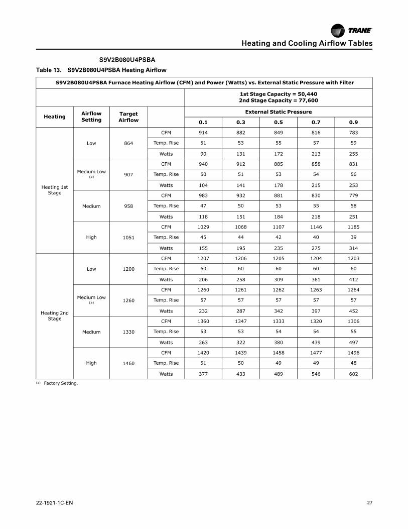
SS99VV22BB008800UU44PPSSBBAA
Table 13. S9V2B080U4PSBA Heating Airflow
S9V2B080U4PSBA Furnace Heating Airflow (CFM) and Power (Watts) vs. External Static Pressure with Filter
1st Stage Capacity = 50,4402nd Stage Capacity = 77,600
Heating AirflowSetting
TargetAirflow
External Static Pressure
0.1 0.3 0.5 0.7 0.9
Heating 1stStage
Low 864
CFM 914 882 849 816 783
Temp. Rise 51 53 55 57 59
Watts 90 131 172 213 255
Medium Low(a) 907
CFM 940 912 885 858 831
Temp. Rise 50 51 53 54 56
Watts 104 141 178 215 253
Medium 958
CFM 983 932 881 830 779
Temp. Rise 47 50 53 55 58
Watts 118 151 184 218 251
High 1051
CFM 1029 1068 1107 1146 1185
Temp. Rise 45 44 42 40 39
Watts 155 195 235 275 314
Heating 2ndStage
Low 1200
CFM 1207 1206 1205 1204 1203
Temp. Rise 60 60 60 60 60
Watts 206 258 309 361 412
Medium Low(a) 1260
CFM 1260 1261 1262 1263 1264
Temp. Rise 57 57 57 57 57
Watts 232 287 342 397 452
Medium 1330
CFM 1360 1347 1333 1320 1306
Temp. Rise 53 53 54 54 55
Watts 263 322 380 439 497
High 1460
CFM 1420 1439 1458 1477 1496
Temp. Rise 51 50 49 49 48
Watts 377 433 489 546 602
(a) Factory Setting.
HHeeaattiinngg aanndd CCoooolliinngg AAiirrffllooww TTaabblleess

28 22-1921-1C-EN
SS99VV22BB008800DD44PPSSBBAA
Table 14. S9V2B080D4PSBA Heating Airflow
S9V2B080D4PSBA Furnace Heating Airflow (CFM) and Power (Watts) vs. External Static Pressure with Filter
1st Stage Capacity = 50,4402nd Stage Capacity = 77,600
Heating AirflowSetting
TargetAirflow
External Static Pressure
0.1 0.3 0.5 0.7 0.9
Heating 1stStage
Low 864
CFM 770 770 770 770 770
Temp. Rise 61 61 61 61 61
Watts 72 118 164 210 256
Medium Low(a) 907
CFM 809 809 809 809 809
Temp. Rise 58 58 58 58 58
Watts 88 134 180 227 273
Medium 958
CFM 854 854 854 854 854
Temp. Rise 54 54 54 54 54
Watts 101 150 198 247 296
High 1051
CFM 993 993 993 993 993
Temp. Rise 47 47 47 47 47
Watts 133 186 239 292 346
Heating 2ndStage
Low 1200
CFM 1082 1082 1082 1082 1082
Temp. Rise 66 66 66 66 66
Watts 181 239 298 357 416
Medium Low(a) 1260
CFM 1190 1190 1190 1190 1190
Temp. Rise 59 59 59 59 59
Watts 206 268 329 390 451
Medium 1330
CFM 1225 1225 1225 1225 1225
Temp. Rise 58 58 58 58 58
Watts 239 303 367 431 495
High 1460
CFM 1227 1227 1227 1227 1227
Temp. Rise 57 57 57 57 57
Watts 320 390 460 530 600
(a) Factory Setting.
HHeeaattiinngg aanndd CCoooolliinngg AAiirrffllooww TTaabblleess

22-1921-1C-EN 29
SS99VV22BB008800UU44PPSSBBAA // SS99VV22BB008800DD44PPSSBBAA
Table 15. S9V2B080U4PSBA / S9V2B080D4PSBA Cooling Airflow
S9V2B080U4PSBA / S9V2B080D4PSBA Furnace Cooling Airflow (CFM) and Power (Watts) vs. External Static Pressurewith Filter
Cooling UnitOutdoor
AirflowSetting(CFM/ton)
External Static Pressure
0.1 0.3 0.5 0.7 0.9
Cooling 2.5 Ton
Cooling 450CFM/Ton
CFM 1125 1125 1125 1125 1125
Watts 155 205 259 316 376
Cooling 420CFM/Ton
CFM 1050 1050 1050 1050 1050
Watts 130 177 228 282 340
Cooling 400CFM/Ton
CFM 1000 1000 1000 1000 1000
Watts 115 160 209 262 317
Cooling 370CFM/Ton
CFM 925 925 925 925 925
Watts 94 136 183 233 286
Cooling 350CFM/Ton
CFM 875 875 875 875 875
Watts 82 122 167 216 267
Cooling 330CFM/Ton
CFM 825 825 825 825 825
Watts 71 110 153 199 249
Cooling 310CFM/Ton
CFM 775 775 775 775 775
Watts 61 98 139 184 233
Cooling 290CFM/Ton
CFM 725 725 725 725 725
Watts 52 87 127 171 218
Cooling 3.0 Ton
Cooling 450CFM/Ton
CFM 1350 1350 1350 1350 1350
Watts 252 311 374 440 508
Cooling 420CFM/Ton
CFM 1260 1260 1260 1260 1260
Watts 209 265 324 386 451
Cooling 400CFM/Ton
CFM 1200 1200 1200 1200 1200
Watts 184 237 294 354 416
Cooling 370CFM/Ton
CFM 1110 1110 1110 1110 1110
Watts 150 199 253 309 369
Cooling 350CFM/Ton
CFM 1050 1050 1050 1050 1050
Watts 130 177 228 282 340
Cooling 330CFM/Ton
CFM 990 990 990 990 990
Watts 112 156 205 258 313
Cooling 310CFM/Ton
CFM 930 930 930 930 930
Watts 95 138 185 235 288
Cooling 290CFM/Ton
CFM 870 870 870 870 870
Watts 81 121 166 214 265
Cooling 3.5 Ton
Cooling 450CFM/Ton
CFM 1575 1575 1575 1575 1575
Watts 383 452 524 599 676
Cooling 420CFM/Ton CFM
1470 1470 1470 1470 1470
HHeeaattiinngg aanndd CCoooolliinngg AAiirrffllooww TTaabblleess
30 22-1921-1C-EN
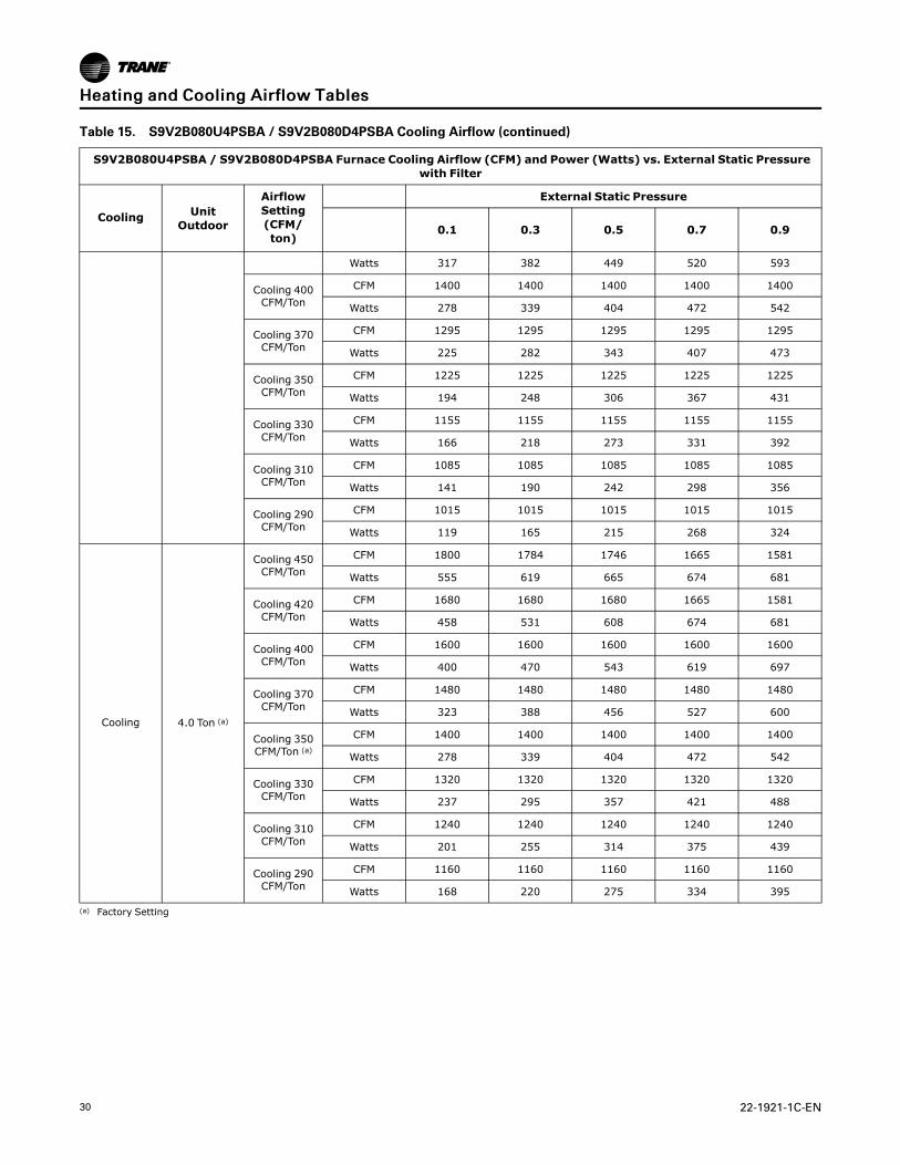
Table 15. S9V2B080U4PSBA / S9V2B080D4PSBA Cooling Airflow (continued)
S9V2B080U4PSBA / S9V2B080D4PSBA Furnace Cooling Airflow (CFM) and Power (Watts) vs. External Static Pressurewith Filter
Cooling UnitOutdoor
AirflowSetting(CFM/ton)
External Static Pressure
0.1 0.3 0.5 0.7 0.9
Watts 317 382 449 520 593
Cooling 400CFM/Ton
CFM 1400 1400 1400 1400 1400
Watts 278 339 404 472 542
Cooling 370CFM/Ton
CFM 1295 1295 1295 1295 1295
Watts 225 282 343 407 473
Cooling 350CFM/Ton
CFM 1225 1225 1225 1225 1225
Watts 194 248 306 367 431
Cooling 330CFM/Ton
CFM 1155 1155 1155 1155 1155
Watts 166 218 273 331 392
Cooling 310CFM/Ton
CFM 1085 1085 1085 1085 1085
Watts 141 190 242 298 356
Cooling 290CFM/Ton
CFM 1015 1015 1015 1015 1015
Watts 119 165 215 268 324
Cooling 4.0 Ton (a)
Cooling 450CFM/Ton
CFM 1800 1784 1746 1665 1581
Watts 555 619 665 674 681
Cooling 420CFM/Ton
CFM 1680 1680 1680 1665 1581
Watts 458 531 608 674 681
Cooling 400CFM/Ton
CFM 1600 1600 1600 1600 1600
Watts 400 470 543 619 697
Cooling 370CFM/Ton
CFM 1480 1480 1480 1480 1480
Watts 323 388 456 527 600
Cooling 350CFM/Ton (a)
CFM 1400 1400 1400 1400 1400
Watts 278 339 404 472 542
Cooling 330CFM/Ton
CFM 1320 1320 1320 1320 1320
Watts 237 295 357 421 488
Cooling 310CFM/Ton
CFM 1240 1240 1240 1240 1240
Watts 201 255 314 375 439
Cooling 290CFM/Ton
CFM 1160 1160 1160 1160 1160
Watts 168 220 275 334 395
(a) Factory Setting
HHeeaattiinngg aanndd CCoooolliinngg AAiirrffllooww TTaabblleess

22-1921-1C-EN 31
SS99VV22CC008800UU55PPSSBBAA
Table 16. S9V2C080U5PSBA Heating Airflow
S9V2C080U5PSBA Furnace Heating Airflow (CFM) and Power (Watts) vs. External Static Pressure with Filter
1st Stage Capacity = 50,4402nd Stage Capacity = 77,600
Heating AirflowSetting
TargetAirflow
External Static Pressure
0.1 0.3 0.5 0.7 0.9
Heating 1stStage
Low 857
CFM 837 870 902 934 967
Temp. Rise 55 53 51 50 48
Watts 65 112 160 208 256
Medium Low(a) 1044
CFM 997 1015 1033 1050 1068
Temp. Rise 46 45 45 44 43
Watts 102 155 209 263 316
Medium 1123
CFM 1067 1094 1121 1148 1175
Temp. Rise 43 42 41 40 39
Watts 123 180 236 293 350
High 1498
CFM 1420 1416 1411 1407 1402
Temp. Rise 32 33 33 33 34
Watts 238 320 402 485 567
Heating 2ndStage
Low 1190
CFM 1129 1148 1168 1188 1208
Temp. Rise 63 62 61 60 59
Watts 127 195 263 331 399
Medium Low(a) 1450
CFM 1387 1395 1404 1412 1420
Temp. Rise 52 51 51 51 51
Watts 248 310 372 434 496
Medium 1560
CFM 1484 1498 1512 1525 1539
Temp. Rise 48 48 47 47 47
Watts 281 358 435 512 589
High 2080
CFM 1954 1956 1959 1961 1964
Temp. Rise 37 37 37 37 37
Watts 597 732 866 1001 1135
(a) Factory Setting.
HHeeaattiinngg aanndd CCoooolliinngg AAiirrffllooww TTaabblleess
32 22-1921-1C-EN
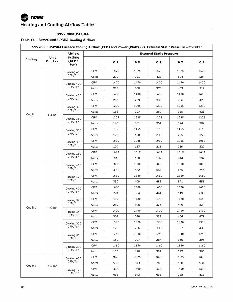
SS99VV22CC008800UU55PPSSBBAA
Table 17. S9V2C080U5PSBA Cooling Airflow
S9V2C080U5PSBA Furnace Cooling Airflow (CFM) and Power (Watts) vs. External Static Pressure with Filter
Cooling UnitOutdoor
AirflowSetting(CFM/ton)
External Static Pressure
0.1 0.3 0.5 0.7 0.9
Cooling 3.5 Ton
Cooling 450CFM/Ton
CFM 1575 1575 1575 1575 1575
Watts 279 351 426 504 584
Cooling 420CFM/Ton
CFM 1470 1470 1470 1470 1470
Watts 233 300 370 443 519
Cooling 400CFM/Ton
CFM 1400 1400 1400 1400 1400
Watts 205 269 336 406 478
Cooling 370CFM/Ton
CFM 1295 1295 1295 1295 1295
Watts 168 227 289 355 423
Cooling 350CFM/Ton
CFM 1225 1225 1225 1225 1225
Watts 145 201 261 324 389
Cooling 330CFM/Ton
CFM 1155 1155 1155 1155 1155
Watts 125 178 235 295 358
Cooling 310CFM/Ton
CFM 1085 1085 1085 1085 1085
Watts 107 157 211 269 329
Cooling 290CFM/Ton
CFM 1015 1015 1015 1015 1015
Watts 91 138 189 244 302
Cooling 4.0 Ton
Cooling 450CFM/Ton
CFM 1800 1800 1800 1800 1800
Watts 399 482 567 655 745
Cooling 420CFM/Ton
CFM 1680 1680 1680 1680 1680
Watts 332 409 488 571 655
Cooling 400CFM/Ton
CFM 1600 1600 1600 1600 1600
Watts 291 364 441 519 600
Cooling 370CFM/Ton
CFM 1480 1480 1480 1480 1480
Watts 237 305 375 449 524
Cooling 350CFM/Ton
CFM 1400 1400 1400 1400 1400
Watts 205 269 336 406 478
Cooling 330CFM/Ton
CFM 1320 1320 1320 1320 1320
Watts 176 236 300 367 436
Cooling 310CFM/Ton
CFM 1240 1240 1240 1240 1240
Watts 150 207 267 330 396
Cooling 290CFM/Ton
CFM 1160 1160 1160 1160 1160
Watts 127 180 237 297 360
Cooling 4.5 Ton
Cooling 450CFM/Ton
CFM 2025 2025 2025 2025 2020
Watts 550 643 740 838 934
Cooling 420CFM/Ton
CFM 1890 1890 1890 1890 1890
Watts 456 543 632 725 819
HHeeaattiinngg aanndd CCoooolliinngg AAiirrffllooww TTaabblleess
22-1921-1C-EN 33
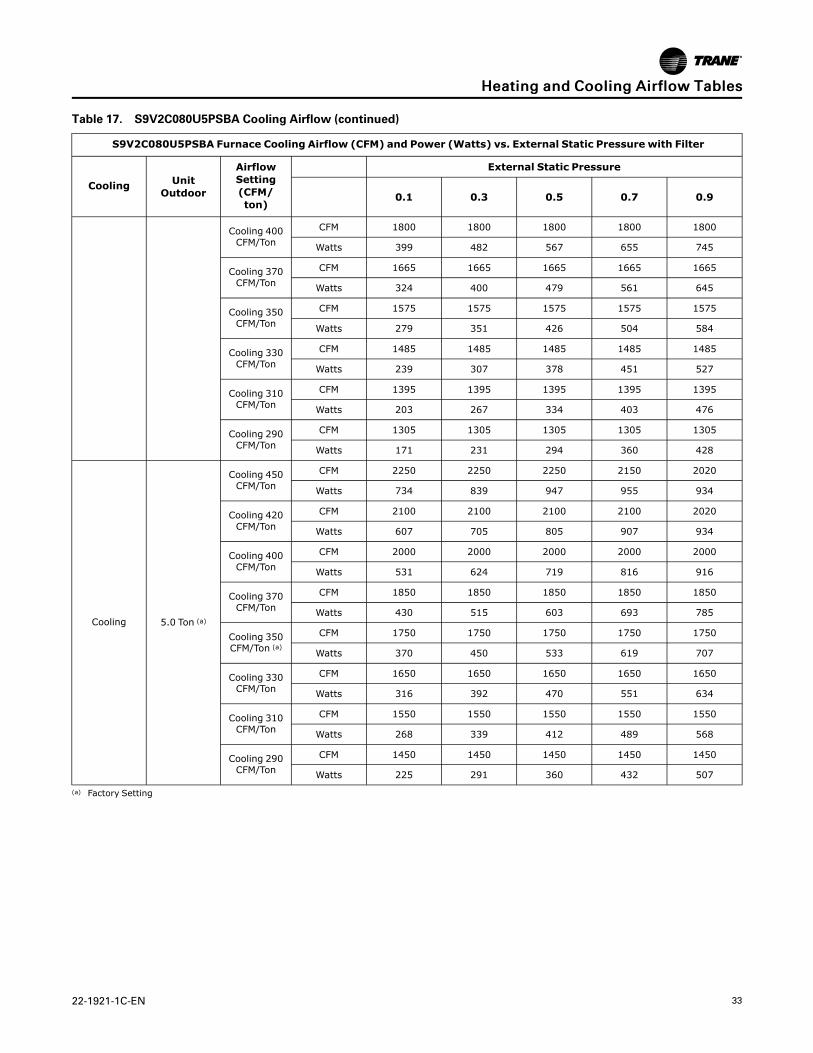
Table 17. S9V2C080U5PSBA Cooling Airflow (continued)
S9V2C080U5PSBA Furnace Cooling Airflow (CFM) and Power (Watts) vs. External Static Pressure with Filter
Cooling UnitOutdoor
AirflowSetting(CFM/ton)
External Static Pressure
0.1 0.3 0.5 0.7 0.9
Cooling 400CFM/Ton
CFM 1800 1800 1800 1800 1800
Watts 399 482 567 655 745
Cooling 370CFM/Ton
CFM 1665 1665 1665 1665 1665
Watts 324 400 479 561 645
Cooling 350CFM/Ton
CFM 1575 1575 1575 1575 1575
Watts 279 351 426 504 584
Cooling 330CFM/Ton
CFM 1485 1485 1485 1485 1485
Watts 239 307 378 451 527
Cooling 310CFM/Ton
CFM 1395 1395 1395 1395 1395
Watts 203 267 334 403 476
Cooling 290CFM/Ton
CFM 1305 1305 1305 1305 1305
Watts 171 231 294 360 428
Cooling 5.0 Ton (a)
Cooling 450CFM/Ton
CFM 2250 2250 2250 2150 2020
Watts 734 839 947 955 934
Cooling 420CFM/Ton
CFM 2100 2100 2100 2100 2020
Watts 607 705 805 907 934
Cooling 400CFM/Ton
CFM 2000 2000 2000 2000 2000
Watts 531 624 719 816 916
Cooling 370CFM/Ton
CFM 1850 1850 1850 1850 1850
Watts 430 515 603 693 785
Cooling 350CFM/Ton (a)
CFM 1750 1750 1750 1750 1750
Watts 370 450 533 619 707
Cooling 330CFM/Ton
CFM 1650 1650 1650 1650 1650
Watts 316 392 470 551 634
Cooling 310CFM/Ton
CFM 1550 1550 1550 1550 1550
Watts 268 339 412 489 568
Cooling 290CFM/Ton
CFM 1450 1450 1450 1450 1450
Watts 225 291 360 432 507
(a) Factory Setting
HHeeaattiinngg aanndd CCoooolliinngg AAiirrffllooww TTaabblleess
34 22-1921-1C-EN
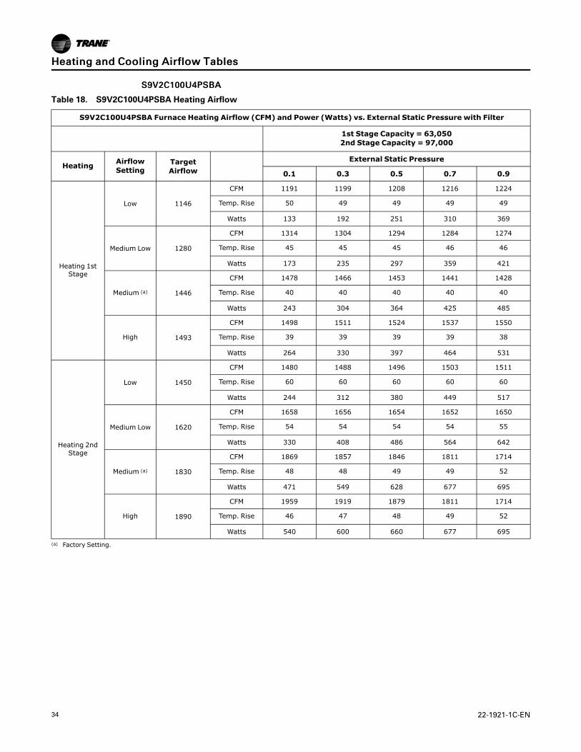
SS99VV22CC110000UU44PPSSBBAA
Table 18. S9V2C100U4PSBA Heating Airflow
S9V2C100U4PSBA Furnace Heating Airflow (CFM) and Power (Watts) vs. External Static Pressure with Filter
1st Stage Capacity = 63,0502nd Stage Capacity = 97,000
Heating AirflowSetting
TargetAirflow
External Static Pressure
0.1 0.3 0.5 0.7 0.9
Heating 1stStage
Low 1146
CFM 1191 1199 1208 1216 1224
Temp. Rise 50 49 49 49 49
Watts 133 192 251 310 369
Medium Low 1280
CFM 1314 1304 1294 1284 1274
Temp. Rise 45 45 45 46 46
Watts 173 235 297 359 421
Medium (a) 1446
CFM 1478 1466 1453 1441 1428
Temp. Rise 40 40 40 40 40
Watts 243 304 364 425 485
High 1493
CFM 1498 1511 1524 1537 1550
Temp. Rise 39 39 39 39 38
Watts 264 330 397 464 531
Heating 2ndStage
Low 1450
CFM 1480 1488 1496 1503 1511
Temp. Rise 60 60 60 60 60
Watts 244 312 380 449 517
Medium Low 1620
CFM 1658 1656 1654 1652 1650
Temp. Rise 54 54 54 54 55
Watts 330 408 486 564 642
Medium (a) 1830
CFM 1869 1857 1846 1811 1714
Temp. Rise 48 48 49 49 52
Watts 471 549 628 677 695
High 1890
CFM 1959 1919 1879 1811 1714
Temp. Rise 46 47 48 49 52
Watts 540 600 660 677 695
(a) Factory Setting.
HHeeaattiinngg aanndd CCoooolliinngg AAiirrffllooww TTaabblleess

22-1921-1C-EN 35
SS99VV22CC110000DD44PPSSBBAA
Table 19. S9V2C100D4PSBA Heating Airflow
S9V2C100D4PSBA Furnace Heating Airflow (CFM) and Power (Watts) vs. External Static Pressure with Filter
1st Stage Capacity = 63,0502nd Stage Capacity = 97,000
Heating AirflowSetting
TargetAirflow
External Static Pressure
0.1 0.3 0.5 0.7 0.9
Heating 1stStage
Low 1080
CFM 1068 1048 1029 1009 989
Temp. Rise 55 57 60 63 66
Watts 101 151 201 251 301
Medium Low 1166
CFM 1158 1113 1068 1023 978
Temp. Rise 51 53 55 57 59
Watts 115 172 229 285 342
Medium (a) 1318
CFM 1326 1272 1218 1164 1111
Temp. Rise 46 48 50 51 53
Watts 153 206 259 312 365
High 1361
CFM 1312 1270 1229 1188 1147
Temp. Rise 46 47 47 48 49
Watts 166 221 276 331 387
Heating 2ndStage
Low 1500
CFM 1514 1478 1441 1404 1367
Temp. Rise 58 60 61 63 64
Watts 223 297 370 443 516
Medium Low 1620
CFM 1620 1588 1556 1523 1491
Temp. Rise 55 56 57 58 59
Watts 276 345 415 484 553
Medium (a) 1830
CFM 1768 1746 1724 1702 1620
Temp. Rise 50 51 52 53 53
Watts 372 446 520 594 668
High 1890
CFM 1810 1783 1756 1729 1702
Temp. Rise 49 50 51 52 52
Watts 405 476 548 677 695
(a) Factory Setting.
HHeeaattiinngg aanndd CCoooolliinngg AAiirrffllooww TTaabblleess
36 22-1921-1C-EN
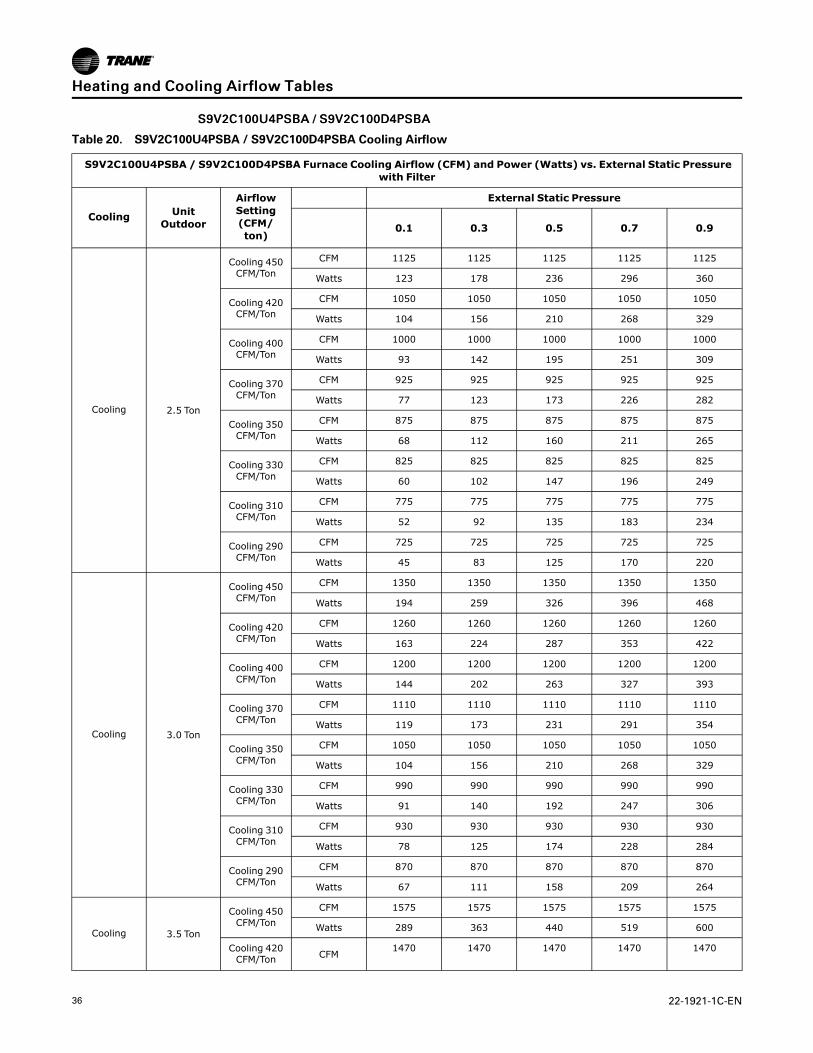
SS99VV22CC110000UU44PPSSBBAA // SS99VV22CC110000DD44PPSSBBAA
Table 20. S9V2C100U4PSBA / S9V2C100D4PSBA Cooling Airflow
S9V2C100U4PSBA / S9V2C100D4PSBA Furnace Cooling Airflow (CFM) and Power (Watts) vs. External Static Pressurewith Filter
Cooling UnitOutdoor
AirflowSetting(CFM/ton)
External Static Pressure
0.1 0.3 0.5 0.7 0.9
Cooling 2.5 Ton
Cooling 450CFM/Ton
CFM 1125 1125 1125 1125 1125
Watts 123 178 236 296 360
Cooling 420CFM/Ton
CFM 1050 1050 1050 1050 1050
Watts 104 156 210 268 329
Cooling 400CFM/Ton
CFM 1000 1000 1000 1000 1000
Watts 93 142 195 251 309
Cooling 370CFM/Ton
CFM 925 925 925 925 925
Watts 77 123 173 226 282
Cooling 350CFM/Ton
CFM 875 875 875 875 875
Watts 68 112 160 211 265
Cooling 330CFM/Ton
CFM 825 825 825 825 825
Watts 60 102 147 196 249
Cooling 310CFM/Ton
CFM 775 775 775 775 775
Watts 52 92 135 183 234
Cooling 290CFM/Ton
CFM 725 725 725 725 725
Watts 45 83 125 170 220
Cooling 3.0 Ton
Cooling 450CFM/Ton
CFM 1350 1350 1350 1350 1350
Watts 194 259 326 396 468
Cooling 420CFM/Ton
CFM 1260 1260 1260 1260 1260
Watts 163 224 287 353 422
Cooling 400CFM/Ton
CFM 1200 1200 1200 1200 1200
Watts 144 202 263 327 393
Cooling 370CFM/Ton
CFM 1110 1110 1110 1110 1110
Watts 119 173 231 291 354
Cooling 350CFM/Ton
CFM 1050 1050 1050 1050 1050
Watts 104 156 210 268 329
Cooling 330CFM/Ton
CFM 990 990 990 990 990
Watts 91 140 192 247 306
Cooling 310CFM/Ton
CFM 930 930 930 930 930
Watts 78 125 174 228 284
Cooling 290CFM/Ton
CFM 870 870 870 870 870
Watts 67 111 158 209 264
Cooling 3.5 Ton
Cooling 450CFM/Ton
CFM 1575 1575 1575 1575 1575
Watts 289 363 440 519 600
Cooling 420CFM/Ton CFM
1470 1470 1470 1470 1470
HHeeaattiinngg aanndd CCoooolliinngg AAiirrffllooww TTaabblleess

22-1921-1C-EN 37
Table 20. S9V2C100U4PSBA / S9V2C100D4PSBA Cooling Airflow (continued)
S9V2C100U4PSBA / S9V2C100D4PSBA Furnace Cooling Airflow (CFM) and Power (Watts) vs. External Static Pressurewith Filter
Cooling UnitOutdoor
AirflowSetting(CFM/ton)
External Static Pressure
0.1 0.3 0.5 0.7 0.9
Watts 241 311 383 458 535
Cooling 400CFM/Ton
CFM 1400 1400 1400 1400 1400
Watts 213 280 349 421 495
Cooling 370CFM/Ton
CFM 1295 1295 1295 1295 1295
Watts 175 237 302 369 439
Cooling 350CFM/Ton
CFM 1225 1225 1225 1225 1225
Watts 152 211 273 338 405
Cooling 330CFM/Ton
CFM 1155 1155 1155 1155 1155
Watts 131 187 247 308 373
Cooling 310CFM/Ton
CFM 1085 1085 1085 1085 1085
Watts 113 166 222 281 343
Cooling 290CFM/Ton
CFM 1015 1015 1015 1015 1015
Watts 96 146 199 256 315
Cooling 4.0 Ton (a)
Cooling 450CFM/Ton
CFM 1800 1800 1800 1800 1714
Watts 410 494 580 669 695
Cooling 420CFM/Ton
CFM 1680 1680 1680 1680 1680
Watts 342 420 502 585 671
Cooling 400CFM/Ton
CFM 1600 1600 1600 1600 1600
Watts 301 376 454 534 617
Cooling 370CFM/Ton
CFM 1480 1480 1480 1480 1480
Watts 246 316 388 464 541
Cooling 350CFM/Ton (a)
CFM 1400 1400 1400 1400 1400
Watts 213 280 349 421 495
Cooling 330CFM/Ton
CFM 1320 1320 1320 1320 1320
Watts 183 247 313 381 452
Cooling 310CFM/Ton
CFM 1240 1240 1240 1240 1240
Watts 157 216 279 344 412
Cooling 290CFM/Ton
CFM 1160 1160 1160 1160 1160
Watts 133 189 248 310 375
(a) Factory Setting
HHeeaattiinngg aanndd CCoooolliinngg AAiirrffllooww TTaabblleess
38 22-1921-1C-EN
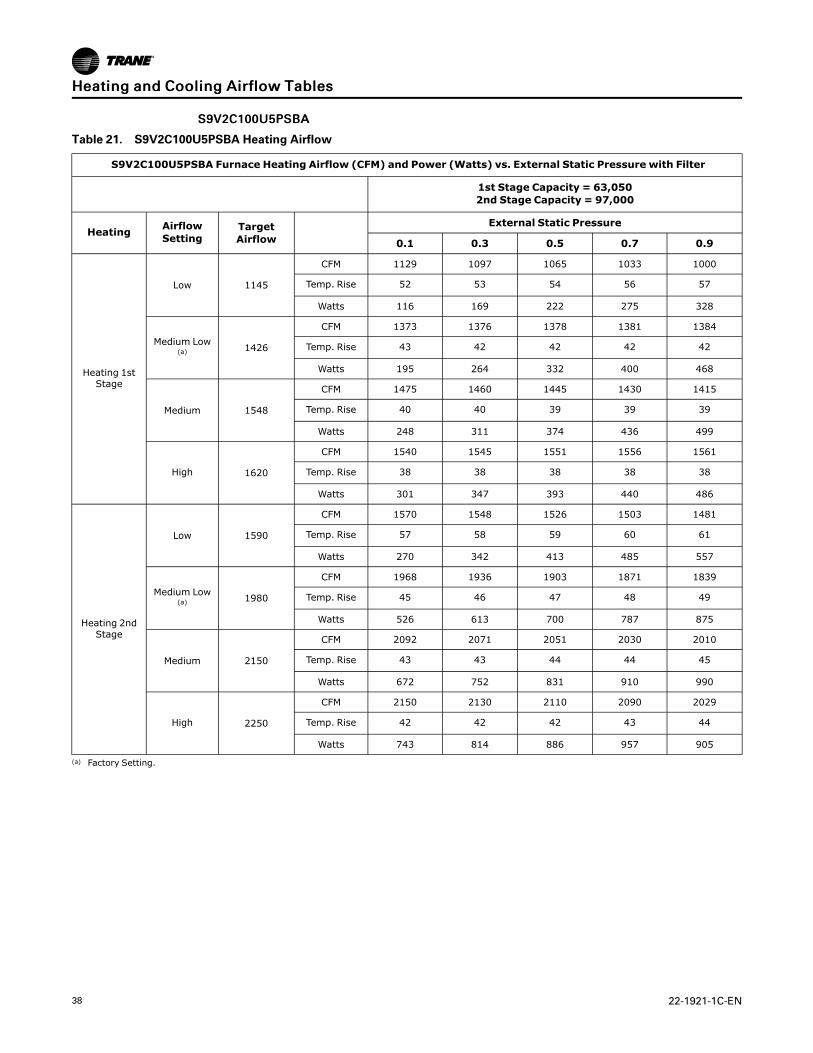
SS99VV22CC110000UU55PPSSBBAA
Table 21. S9V2C100U5PSBA Heating Airflow
S9V2C100U5PSBA Furnace Heating Airflow (CFM) and Power (Watts) vs. External Static Pressure with Filter
1st Stage Capacity = 63,0502nd Stage Capacity = 97,000
Heating AirflowSetting
TargetAirflow
External Static Pressure
0.1 0.3 0.5 0.7 0.9
Heating 1stStage
Low 1145
CFM 1129 1097 1065 1033 1000
Temp. Rise 52 53 54 56 57
Watts 116 169 222 275 328
Medium Low(a) 1426
CFM 1373 1376 1378 1381 1384
Temp. Rise 43 42 42 42 42
Watts 195 264 332 400 468
Medium 1548
CFM 1475 1460 1445 1430 1415
Temp. Rise 40 40 39 39 39
Watts 248 311 374 436 499
High 1620
CFM 1540 1545 1551 1556 1561
Temp. Rise 38 38 38 38 38
Watts 301 347 393 440 486
Heating 2ndStage
Low 1590
CFM 1570 1548 1526 1503 1481
Temp. Rise 57 58 59 60 61
Watts 270 342 413 485 557
Medium Low(a) 1980
CFM 1968 1936 1903 1871 1839
Temp. Rise 45 46 47 48 49
Watts 526 613 700 787 875
Medium 2150
CFM 2092 2071 2051 2030 2010
Temp. Rise 43 43 44 44 45
Watts 672 752 831 910 990
High 2250
CFM 2150 2130 2110 2090 2029
Temp. Rise 42 42 42 43 44
Watts 743 814 886 957 905
(a) Factory Setting.
HHeeaattiinngg aanndd CCoooolliinngg AAiirrffllooww TTaabblleess

22-1921-1C-EN 39
SS99VV22CC110000DD55PPSSBBAA
Table 22. S9V2C100D5PSBA Heating Airflow
S9V2C100D5PSBA Furnace Heating Airflow (CFM) and Power (Watts) vs. External Static Pressure with Filter
1st Stage Capacity = 63,0502nd Stage Capacity = 97,000
Heating AirflowSetting
TargetAirflow
External Static Pressure
0.1 0.3 0.5 0.7 0.9
Heating 1stStage
Low 1094
CFM 1094 1023 952 881 809
Temp. Rise 53 57 61 65 69
Watts 100 153 206 258 311
Medium Low 1296
CFM 1296 1212 1127 1043 958
Temp. Rise 45 48 51 55 58
Watts 156 216 276 337 397
Medium (a) 1346
CFM 1346 1259 1171 1083 996
Temp. Rise 43 46 49 53 56
Watts 172 234 297 359 421
High 1620
CFM 1620 1515 1409 1304 1198
Temp. Rise 36 38 41 44 46
Watts 284 358 431 504 578
Heating 2ndStage
Low 1520
CFM 1437 1420 1403 1385 1368
Temp. Rise 62 63 63 64 65
Watts 236 308 380 453 525
Medium Low 1800
CFM 1744 1712 1680 1649 1617
Temp. Rise 51 52 53 54 55
Watts 378 462 545 629 713
Medium (a) 1870
CFM 1811 1779 1747 1715 1683
Temp. Rise 49 50 51 52 53
Watts 421 508 594 681 768
High 2250
CFM 2211 2109 2006 1903 1800
Temp. Rise 40 42 45 47 49
Watts 714 817 920 1023 905
(a) Factory Setting.
HHeeaattiinngg aanndd CCoooolliinngg AAiirrffllooww TTaabblleess

40 22-1921-1C-EN
SS99VV22CC110000UU55PPSSBBAA // SS99VV22CC110000DD55PPSSBBAA
Table 23. S9V2C100U5PSBA / S9V2C100D5PSBA Cooling Airflow
S9V2C100U5PSBA / S9V2C100D5PSBA Furnace Cooling Airflow (CFM) and Power (Watts) vs. External Static Pressurewith Filter
Cooling UnitOutdoor
AirflowSetting(CFM/ton)
External Static Pressure
0.1 0.3 0.5 0.7 0.9
Cooling 3.5 Ton
Cooling 450CFM/Ton
CFM 1575 1575 1575 1575 1575
Watts 263 333 406 481 558
Cooling 420CFM/Ton
CFM 1470 1470 1470 1470 1470
Watts 218 283 352 423 496
Cooling 400CFM/Ton
CFM 1400 1400 1400 1400 1400
Watts 191 254 319 388 458
Cooling 370CFM/Ton
CFM 1295 1295 1295 1295 1295
Watts 155 214 275 340 406
Cooling 350CFM/Ton
CFM 1225 1225 1225 1225 1225
Watts 134 190 249 311 375
Cooling 330CFM/Ton
CFM 1155 1155 1155 1155 1155
Watts 115 168 225 284 346
Cooling 310CFM/Ton
CFM 1085 1085 1085 1085 1085
Watts 98 148 202 259 319
Cooling 290CFM/Ton
CFM 1015 1015 1015 1015 1015
Watts 83 131 182 237 294
Cooling 4.0 Ton
Cooling 450CFM/Ton
CFM 1800 1800 1800 1800 1800
Watts 381 460 542 627 713
Cooling 420CFM/Ton
CFM 1680 1680 1680 1680 1680
Watts 314 388 466 545 627
Cooling 400CFM/Ton
CFM 1600 1600 1600 1600 1600
Watts 275 345 419 496 574
Cooling 370CFM/Ton
CFM 1480 1480 1480 1480 1480
Watts 222 288 357 428 502
Cooling 350CFM/Ton
CFM 1400 1400 1400 1400 1400
Watts 191 254 319 388 458
Cooling 330CFM/Ton
CFM 1320 1320 1320 1320 1320
Watts 163 223 285 351 418
Cooling 310CFM/Ton
CFM 1240 1240 1240 1240 1240
Watts 139 195 254 317 381
Cooling 290CFM/Ton
CFM 1160 1160 1160 1160 1160
Watts 117 170 226 286 348
Cooling 4.5 Ton
Cooling 450CFM/Ton
CFM 2025 2025 2025 2025 2025
Watts 531 620 711 805 901
Cooling 420CFM/Ton CFM 1890 1890 1890 1890 1890
HHeeaattiinngg aanndd CCoooolliinngg AAiirrffllooww TTaabblleess

22-1921-1C-EN 41
Table 23. S9V2C100U5PSBA / S9V2C100D5PSBA Cooling Airflow (continued)
S9V2C100U5PSBA / S9V2C100D5PSBA Furnace Cooling Airflow (CFM) and Power (Watts) vs. External Static Pressurewith Filter
Cooling UnitOutdoor
AirflowSetting(CFM/ton)
External Static Pressure
0.1 0.3 0.5 0.7 0.9
Watts 437 520 606 694 784
Cooling 400CFM/Ton
CFM 1800 1800 1800 1800 1800
Watts 381 460 542 627 713
Cooling 370CFM/Ton
CFM 1665 1665 1665 1665 1665
Watts 307 380 457 536 616
Cooling 350CFM/Ton
CFM 1575 1575 1575 1575 1575
Watts 263 333 406 481 558
Cooling 330CFM/Ton
CFM 1485 1485 1485 1485 1485
Watts 224 290 359 431 505
Cooling 310CFM/Ton
CFM 1395 1395 1395 1395 1395
Watts 189 252 317 386 456
Cooling 290CFM/Ton
CFM 1305 1305 1305 1305 1305
Watts 158 217 279 344 411
Cooling 5.0 Ton (a)
Cooling 450CFM/Ton
CFM 2250 2250 2242 2137 2029
Watts 717 816 909 908 905
Cooling 420CFM/Ton
CFM 2100 2100 2100 2100 2029
Watts 589 681 776 873 905
Cooling 400CFM/Ton
CFM 2000 2000 2000 2000 2000
Watts 512 600 691 784 878
Cooling 370CFM/Ton
CFM 1850 1850 1850 1850 1850
Watts 411 492 577 663 752
Cooling 350CFM/Ton (a)
CFM 1750 1750 1750 1750 1750
Watts 352 429 509 592 676
Cooling 330CFM/Ton
CFM 1650 1650 1650 1650 1650
Watts 299 372 448 526 606
Cooling 310CFM/Ton
CFM 1550 1550 1550 1550 1550
Watts 252 320 392 467 543
Cooling 290CFM/Ton
CFM 1450 1450 1450 1450 1450
Watts 210 275 342 413 485
(a) Factory Setting
HHeeaattiinngg aanndd CCoooolliinngg AAiirrffllooww TTaabblleess

42 22-1921-1C-EN
SS99VV22DD112200UU55PPSSBBAA
Table 24. S9V2D120U5PSBA Heating Airflow
S9V2D120U5PSBA Furnace Heating Airflow (CFM) and Power (Watts) vs. External Static Pressure with Filter
1st Stage Capacity = 75,6602nd Stage Capacity = 116,400
Heating AirflowSetting
TargetAirflow
External Static Pressure
0.1 0.3 0.5 0.7 0.9
Heating 1stStage
Low 1123
CFM 1138 1158 1178 1198 1218
Temp. Rise 61 60 59 58 57
Watts 115 176 236 297 358
Medium Low 1332
CFM 1371 1383 1394 1406 1417
Temp. Rise 51 50 50 49 49
Watts 182 251 320 389 457
Medium (a) 1404
CFM 1440 1450 1461 1471 1482
Temp. Rise 48 48 48 47 47
Watts 208 283 357 431 505
High 1620
CFM 1669 1674 1680 1685 1691
Temp. Rise 42 42 41 41 41
Watts 315 388 460 533 605
Heating 2ndStage
Low 1560
CFM 1654 1637 1621 1604 1587
Temp. Rise 65 66 67 67 68
Watts 291 360 430 499 568
Medium Low 1850
CFM 1980 1951 1922 1893 1864
Temp. Rise 55 56 57 58 58
Watts 456 539 621 704 787
Medium (a) 1950
CFM 2075 2037 1999 1961 1923
Temp. Rise 52 53 54 55 56
Watts 527 611 696 781 865
High 2250
CFM 2280 2197 2114 2032 1949
Temp. Rise 48 50 52 54 56
Watts 795 819 842 865 888
(a) Factory Setting.
HHeeaattiinngg aanndd CCoooolliinngg AAiirrffllooww TTaabblleess

22-1921-1C-EN 43
SS99VV22DD112200DD55PPSSBBAA
Table 25. S9V2D120D5PSBA Heating Airflow
S9V2D120D5PSBA Furnace Heating Airflow (CFM) and Power (Watts) vs. External Static Pressure with Filter
1st Stage Capacity = 75,6602nd Stage Capacity = 116,400
Heating AirflowSetting
TargetAirflow
External Static Pressure
0.1 0.3 0.5 0.7 0.9
Heating 1stStage
Low 1160
CFM 1234 1240 1246 1252 1258
Temp. Rise 56 56 56 55 55
Watts 137 198 258 319 380
Medium Low 1332
CFM 1305 1311 1318 1325 1332
Temp. Rise 53 53 53 52 52
Watts 158 221 284 347 410
Medium 1404
CFM 1324 1510 1697 1884 2070
Temp. Rise 53 46 39 32 25
Watts 179 246 313 380 447
High (a) 1620
CFM 1598 1484 1371 1257 1144
Temp. Rise 44 47 49 52 54
Watts 266 316 366 416 466
Heating 2ndStage
Low 1750
CFM 1687 1673 1659 1645 1631
Temp. Rise 63 64 64 65 65
Watts 327 407 487 568 648
Medium Low 1850
CFM 1788 1771 1754 1738 1721
Temp. Rise 60 60 61 61 62
Watts 380 464 549 633 718
Medium 1950
CFM 1891 1862 1833 1803 1774
Temp. Rise 56 57 58 60 61
Watts 424 524 624 724 824
High (a) 2250
CFM 2080 2100 2120 2140 2160
Temp. Rise 51 51 51 51 51
Watts 708 768 828 888 948
(a) Factory Setting.
HHeeaattiinngg aanndd CCoooolliinngg AAiirrffllooww TTaabblleess

44 22-1921-1C-EN
SS99VV22DD112200UU55PPSSBBAA // SS99VV22DD112200DD55PPSSBBAA
Table 26. S9V2D120U5PSBA / S9V2D120D5PSBA Cooling Airflow
S9V2D120U5PSBA / S9V2D120D5PSBA Furnace Cooling Airflow (CFM) and Power (Watts) vs. External Static Pressurewith Filter
Cooling UnitOutdoor
AirflowSetting(CFM/ton)
External Static Pressure
0.1 0.3 0.5 0.7 0.9
Cooling 3.5 Ton
Cooling 450CFM/Ton
CFM 1575 1575 1575 1575 1575
Watts 248 316 387 461 537
Cooling 420CFM/Ton
CFM 1470 1470 1470 1470 1470
Watts 206 270 337 407 479
Cooling 400CFM/Ton
CFM 1400 1400 1400 1400 1400
Watts 181 243 307 374 443
Cooling 370CFM/Ton
CFM 1295 1295 1295 1295 1295
Watts 148 205 265 328 393
Cooling 350CFM/Ton
CFM 1225 1225 1225 1225 1225
Watts 128 182 240 300 363
Cooling 330CFM/Ton
CFM 1155 1155 1155 1155 1155
Watts 111 162 217 274 335
Cooling 310CFM/Ton
CFM 1085 1085 1085 1085 1085
Watts 95 143 195 250 309
Cooling 290CFM/Ton
CFM 1015 1015 1015 1015 1015
Watts 80 126 176 228 285
Cooling 4.0 Ton
Cooling 450CFM/Ton
CFM 1800 1800 1800 1800 1800
Watts 356 433 514 597 682
Cooling 420CFM/Ton
CFM 1680 1680 1680 1680 1680
Watts 295 368 443 521 601
Cooling 400CFM/Ton
CFM 1600 1600 1600 1600 1600
Watts 258 328 400 475 552
Cooling 370CFM/Ton
CFM 1480 1480 1480 1480 1480
Watts 210 274 342 412 484
Cooling 350CFM/Ton
CFM 1400 1400 1400 1400 1400
Watts 181 243 307 374 443
Cooling 330CFM/Ton
CFM 1320 1320 1320 1320 1320
Watts 155 213 274 338 405
Cooling 310CFM/Ton
CFM 1240 1240 1240 1240 1240
Watts 132 187 245 306 369
Cooling 290CFM/Ton
CFM 1160 1160 1160 1160 1160
Watts 112 163 218 276 337
Cooling 4.5 Ton
Cooling 450CFM/Ton
CFM 2025 2025 2025 2025 2025
Watts 492 579 669 761 855
Cooling 420CFM/Ton CFM 1890 1890 1890 1890 1890
HHeeaattiinngg aanndd CCoooolliinngg AAiirrffllooww TTaabblleess
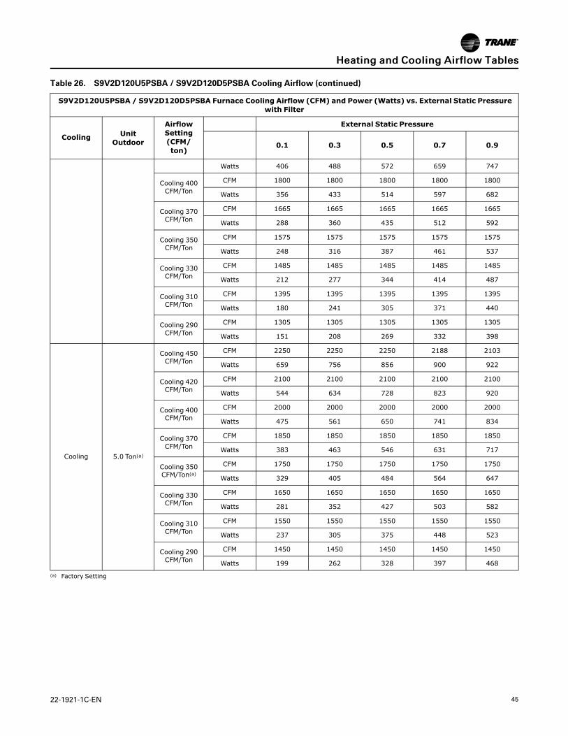
22-1921-1C-EN 45
Table 26. S9V2D120U5PSBA / S9V2D120D5PSBA Cooling Airflow (continued)
S9V2D120U5PSBA / S9V2D120D5PSBA Furnace Cooling Airflow (CFM) and Power (Watts) vs. External Static Pressurewith Filter
Cooling UnitOutdoor
AirflowSetting(CFM/ton)
External Static Pressure
0.1 0.3 0.5 0.7 0.9
Watts 406 488 572 659 747
Cooling 400CFM/Ton
CFM 1800 1800 1800 1800 1800
Watts 356 433 514 597 682
Cooling 370CFM/Ton
CFM 1665 1665 1665 1665 1665
Watts 288 360 435 512 592
Cooling 350CFM/Ton
CFM 1575 1575 1575 1575 1575
Watts 248 316 387 461 537
Cooling 330CFM/Ton
CFM 1485 1485 1485 1485 1485
Watts 212 277 344 414 487
Cooling 310CFM/Ton
CFM 1395 1395 1395 1395 1395
Watts 180 241 305 371 440
Cooling 290CFM/Ton
CFM 1305 1305 1305 1305 1305
Watts 151 208 269 332 398
Cooling 5.0 Ton(a)
Cooling 450CFM/Ton
CFM 2250 2250 2250 2188 2103
Watts 659 756 856 900 922
Cooling 420CFM/Ton
CFM 2100 2100 2100 2100 2100
Watts 544 634 728 823 920
Cooling 400CFM/Ton
CFM 2000 2000 2000 2000 2000
Watts 475 561 650 741 834
Cooling 370CFM/Ton
CFM 1850 1850 1850 1850 1850
Watts 383 463 546 631 717
Cooling 350CFM/Ton(a)
CFM 1750 1750 1750 1750 1750
Watts 329 405 484 564 647
Cooling 330CFM/Ton
CFM 1650 1650 1650 1650 1650
Watts 281 352 427 503 582
Cooling 310CFM/Ton
CFM 1550 1550 1550 1550 1550
Watts 237 305 375 448 523
Cooling 290CFM/Ton
CFM 1450 1450 1450 1450 1450
Watts 199 262 328 397 468
(a) Factory Setting
HHeeaattiinngg aanndd CCoooolliinngg AAiirrffllooww TTaabblleess

46 22-1921-1C-EN
Maximum Vent Length Table
Maximum Vent Length Table Maximum Total Equivalent Length In Feetfor Vent and Inlet Air (See Notes)
Model 2 Inch or 2.5 Inch Pipe 3 Inch or 4 Inch Pipe
Altitude 0–2,000 FeetS9V2B040U3PS, S9V2B040D3PS,S9V2B060U3PS, S9V2B060D3PS,
S9V2B060U4PS200 200
S9V2B080U3PS, S9V2B080D3PS,S9V2B080U4PS, S9V2B080D4PS,
S9V2C080U5PS100 200
S9V2C100U4PS, S9V2C100D4PS,S9V2C100U5PS, S9V2C100D5PS 50 200
S9V2D120U5PS, S9V2D120D5PS Note 1 200
Altitude 2,001–5,400 FeetS9V2B040U3PS, S9V2B040D3PS,S9V2B060U3PS, S9V2B060D3PS,
S9V2B060U4PS200 200
S9V2B080U3PS, S9V2B080D3PS,S9V2B080U4PS, S9V2B080D4PS,
S9V2C080U5PS80 120
S9V2C100U4PS, S9V2C100D4PS,S9V2C100U5PS, S9V2C100D5PS 50 150
S9V2D120U5PS, S9V2D120D5PS Note 1 200
Altitude 5,401–7,800 FeetS9V2B040U3PS, S9V2B040D3PS,S9V2B060U3PS, S9V2B060D3PS,
S9V2B060U4PS100 150
S9V2B080U3PS, S9V2B080D3PS,S9V2B080U4PS, S9V2B080D4PS,
S9V2C080U5PS50 70
S9V2C100U4PS, S9V2C100D4PS,S9V2C100U5PS, S9V2C100D5PS Note 1 100
S9V2D120U5PS, S9V2D120D5PS Note 1 100
Altitude 7,801–10,100 FeetS9V2B040U3PS, S9V2B040D3PS,S9V2B060U3PS, S9V2B060D3PS,
S9V2B060U4PS90 90
S9V2B080U3PS, S9V2B080D3PS,S9V2B080U4PS, S9V2B080D4PS,
S9V2C080U5PSNote 1 50
S9V2C100U4PS, S9V2C100D4PS,S9V2C100U5PS, S9V2C100D5PS Note 1 50
S9V2D120U5PS, S9V2D120D5PS Note 1 50Notes:
1. Not allowed
2. FOR DURAVENTMANUFACTUREDMODULAR VENTING SYSTEMS THAT ARE IN THE APPROVED VENT PIPE MATERIAL TABLE,EQUIVALENT VENT LENGTHSMAY BE DIFFERENT FROMWHAT IS SHOWN ABOVE. REFER TO THE VENTING SYSTEMMANUFACTURER'S INSTALLATION INSTRUCTIONS FOR APPROPRIATE VENTING DIAMETERS AND EQUIVALENT LENGTHS.
3. Minimum vent length for all models: 15' equivalent.
4. DO NOT MIX PIPE DIAMETERS IN THE SAME LENGTH OF PIPE OUTSIDE THE FURNACE CABINET (Except adapters at the top of the furnace).If different inlet and vent pipe sizes are used, the vent pipe must adhere to the maximum length limit shown in the table above (See note 7below for exception). The inlet pipe can be of a larger diameter, but never smaller than the vent pipe.
5. MAXIMUM PIPE LENGTHS MUST NOT BE EXCEEDED! THE LENGTH SHOWN IS NOTA COMBINED TOTAL, IT IS THE MAXIMUM LENGTH OFEACH (Vent or Inlet air pipes).
6. One SHORTradius 90° elbow is equivalent to 10' of 4" pipe, 10' of 3" pipe, or 8’ of 2" pipe. One LONG radius elbow is equivalent to 6' of 4"pipe, 7’ of 3" pipe, or 5' of 2" pipe. Two 45° elbows equal one 90° LONG elbow. One MITERED elbow is equivalent to 12’ of 3” pipe or 12’ of2” pipe.
7. The termination tee or bend must be included in the total number of elbows. If the BAYAIR30AVENTA or BAYAIR30CNVENT termination kitis used, the equivalent length of pipe is 5 feet. For BAYVENT200B and BAYVENTCN200B the equivalent length is 0 feet.
8. For Canadian applications, venting systems must meet ULC-S636 requirements.
9. The INLET AIR of one pipe systems require the installation of a minimum of one 90° elbow (to prevent dust and debris from falling straightinto the furnace).

22-1921-1C-EN 47
S9V2 Wiring Diagram
S9V2 Wiring Diagram and Schematic

48 22-1921-1C-EN
SS99VV22 WWiirriinngg DDiiaaggrraamm

22-1921-1C-EN 49
Electrical ConnectionsMake wiring connections to the unit as indicated on enclosed wiring diagram. As with all gas appliances using electrical power, this furnace shallbe connected into a permanently live electric circuit. It is recommended that furnace be provided with a separate "circuit protection device"electric circuit. The furnace must be electrically grounded in accordance with local codes or in the absence of local codes with the NationalElectrical Code, ANSI/NFPA 70 or CSA C22.1 Electrical Code, if an external electrical source is utilized. The integrated furnace control ispolarity sensitive. The hot leg of the 120V power supply must be connected to the black power lead as indicated on the wiring diagram.Refer to the SERVICE FACTS literature and unit wiring diagram attached to furnace.
Field Wiring
O
BK BK
Y2
Y1 Y1
B/C B/C
W2
W1W1
GG
RR
O
Y1
B/C
Two StageThermostat Furnace
Furnace IFC
Outdoor Unit(No Transformer)
SEE NOTE 2 BK JUMPER
SEE NOTE 1
Y2
W2
Y2
FIELD WIRING DIAGRAM FOR TWO STAGE HEATING THERMOSTAT, TWO STAGE COOLING
NOTES:1) For PWM (BK) enabled thermostats, cut the BK jumper on the IFC and connect wiring.2) The factory Y1-O jumper must remain in place for proper LED read out in cooling mode.3) Y1 and Y2 wiring from the thermostat must connect to the IFC for proper airflow and LED readout.4) Single compressor and two compressor airflow is auto- matically set with the IFC Menu optionsin ODU section. 2-1=2 stage / 1 compressor (1st stage airflow = 75%) 2-2=2 stage / 2 compressors (1st stage airflow = 50%)
INTER-COMPONENT WIRING
24 V FIELD WIRING24 V FACTORY WIRING
O
BK BK
Y2
Y1 Y1
B/C B/C
W2W2
W1W1
GG
RR
O
Y1
Two StageThermostat Furnace
Outdoor Unit(No Transformer)
SEE NOTE 2 O
R
X2
Y2
NOTES:1) For PWM (BK) enabled thermostats, cut the BK jumper on the IFC and connect wiring.2) Remove the factory Y1-O jumper for HP systems for proper LED read out.3) Y1 and Y2 wiring from the thermostat must connect to Y1 and Y2 of the IFC for proper airflow and LED readout.4) Single compressor and two compressor airflow is automatically set with the IFC Menu options in ODU section. 2-1=2 stage / 1 compressor (1st stage airflow = 75%) 2-2=2 stage / 2 compressors (1st stage airflow = 50%)
INTER-COMPONENT WIRING
24 V FIELD WIRING24 V FACTORY WIRING
R-BKJUMPER
SEE NOTE 1
Furnace IFC
FIELD WIRING DIAGRAM FOR TWO STAGE HEATING THERMOSTAT, TWO STAGE HEAT PUMP
Y2
B/C

50 22-1921-1C-EN
O
BK BK
Y2
Y1 Y1
B/C B/C
W2
W1W1
GG
RR
O
Y1
B/C
Single StageThermostat Furnace
Outdoor Unit(No Transformer)
SEE NOTE 2
SEE NOTE 4
FIELD WIRING DIAGRAM FOR SINGLE STAGE HEATING THERMOSTAT, SINGLE STAGE COOLING
NOTES:1) For PWM (BK) enabled thermostats, cut the BK jumper on the IFC and connect wiring.2) The factory Y1-O jumper must remain in place for proper LED read out in cooling mode.3) Y1 wiring from the thermostat must connect to Y1 of the IFC for proper airflow and LED readout.4) Place field supplied jumper between W1 and W2 on the IFC. Interstage delay is factory set for 10 minutes but is field adjustable with the Menu option in the ISD section.5) Single stage airflow is set with the IFC Menu options in ODU section. Select 1-1.
INTER-COMPONENT WIRING
24 V FIELD WIRING24 V FACTORY WIRING
Furnace IFC
BK JUMPERSEE NOTE 1
O
BK BK
Y2
Y1 Y1
B/C B/C
W2
W1W1
GG
RR
O
Y1
B/C
Single StageThermostat Furnace
Outdoor Unit(No Transformer)
SEE NOTE 2
SEE NOTE 4
O
R
X2
FIELD WIRING DIAGRAM FOR SINGLE STAGE HEATING THERMOSTAT, SINGLE STAGE HEAT PUMP
NOTES:1) For PWM (BK) enabled thermostats, cut the BK jumper on the IFC and connect wiring.2) Remove the factory Y1-O jumper for HP systems for proper LED read out.3) Y1 wiring from the thermostat must connect to Y1 of the IFC for proper airflow and LED readout.4) Place field supplied jumper between W1 and W2 on the IFC. Interstage delay is factory set for 10 minutes but is field adjustable with the Menu option in the ISD section.5) Single stage airflow is set with the IFC Menu options in ODU section. Select 1-1.
INTER-COMPONENT WIRING
24 V FIELD WIRING24 V FACTORY WIRING
Furnace IFC
BK JUMPERSEE NOTE 1
EElleeccttrriiccaall CCoonnnneeccttiioonnss

22-1921-1C-EN 51
Outline Drawings

52 22-1921-1C-EN
OOuuttlliinnee DDrraawwiinnggss

22-1921-1C-EN 53
OOuuttlliinnee DDrraawwiinnggss

54 22-1921-1C-EN
OOuuttlliinnee DDrraawwiinnggss

22-1921-1C-EN 55
OOuuttlliinnee DDrraawwiinnggss

56 22-1921-1C-EN
OOuuttlliinnee DDrraawwiinnggss

22-1921-1C-EN 57
NNootteess

58 22-1921-1C-EN
NNootteess

22-1921-1C-EN 59
NNootteess

Ingersoll Rand (NYSE: IR) advances the quality of life by creating comfortable, sustainable and efficientenvironments. Our people and our family of brands— including Club Car®, Ingersoll Rand®, Thermo King® andTrane®—work together to enhance the quality and comfort of air in homes and buildings; transport and protectfood and perishables; and increase industrial productivity and efficiency. We are a global business committed to aworld of sustainable progress and enduring results.
ingersollrand.com
Ingersoll Rand has a policy of continuous product and product data improvements and reserves the right to change design and specificationswithout notice.We are committed to using environmentally conscious print practices.
22-1921-1C — EN 29 Mar 2017
Supersedes 22-1921-1B-EN (September 2016) ©2016 Ingersoll Rand | all rights reserved
Recommended