Page 1 of 18 10/1/2013
TENSOR Multi Axis Test System
Team Corporation
February 2012
Page 2 of 18 10/1/2013
Table of Contents
1 Introduction ....................................................................................................................... 3 2 Team Corporation’s MDoF Credentials................................................................................ 5 3 Applying ED Shakers to MDoF Systems ............................................................................... 5
3.1 Degrees of Freedom and Over Constraint ....................................................................... 6 4 Shaker to Table Connection ................................................................................................ 7 5 TENSOR Design ................................................................................................................... 8
5.1 TENSOR 900 Design Features ........................................................................................ 10 5.2 TENSOR 18kN Design Features ...................................................................................... 13
6 Conclusion ........................................................................................................................ 18

Page 3 of 18 10/1/2013
1 Introduction
Vibration testing is evolving at a rapid pace. Driven by market pressures for greater reliability, improved
realism in testing methodology is in demand. There is widespread consensus that simultaneously exciting
a test object in multiple axes will reproduce real-world stress loading. Consequently Multiple Degree of
Freedom (MDoF) testing is believed to be the path to enhanced product reliability with the added benefit
of possible test time compression. Simultaneously exciting all axes and rotations, MDoF testing is in the
process of being codified in testing standards, most notably being Method 527 in MIL STD 810(G). While
not yet a required test process, MDoF testing is being rigorously investigated and quantified by luminaries
in the field. It is anticipated that the results of these efforts will result in the implementation of MDoF
testing as a requirement for mission-critical devices in the very near future.
Reproducing the full range of measured field data in MDoF requires a vibration test system that can
create and control translations and rotations of the test platform simultaneously through the desired
frequency band. A number of successful designs have been implemented that achieve this goal, albeit
with relatively modest bandwidths. MAST systems, the CUBE, and hexapods or Stewart Platforms
(pictured below and on the following page) all have the ability to accurately reproduce measured MDoF
data. However, MAST systems are limited to roughly 50 Hz, Stewart Platforms to perhaps 250 Hz and the
most recent CUBE design, the Model 4, can precisely control through 500 Hz. While these frequency
bands provide utility for some tests, the vast majority of existing test standards for single axis excitation
extends through 2 kHz.
Figure 1 Typical MAST system with 50 Hz Time Wave Replication

Page 4 of 18 10/1/2013
Figure 2 Team CUBE system performing 3 axis 500 Hz random profiles
Figure 3 Stewart Platform or Hexapod
Page 5 of 18 10/1/2013
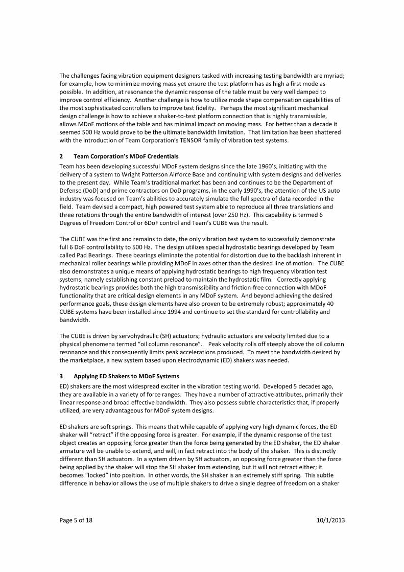
The challenges facing vibration equipment designers tasked with increasing testing bandwidth are myriad;
for example, how to minimize moving mass yet ensure the test platform has as high a first mode as
possible. In addition, at resonance the dynamic response of the table must be very well damped to
improve control efficiency. Another challenge is how to utilize mode shape compensation capabilities of
the most sophisticated controllers to improve test fidelity. Perhaps the most significant mechanical
design challenge is how to achieve a shaker-to-test platform connection that is highly transmissible,
allows MDoF motions of the table and has minimal impact on moving mass. For better than a decade it
seemed 500 Hz would prove to be the ultimate bandwidth limitation. That limitation has been shattered
with the introduction of Team Corporation’s TENSOR family of vibration test systems.
2 Team Corporation’s MDoF Credentials
Team has been developing successful MDoF system designs since the late 1960’s, initiating with the
delivery of a system to Wright Patterson Airforce Base and continuing with system designs and deliveries
to the present day. While Team’s traditional market has been and continues to be the Department of
Defense (DoD) and prime contractors on DoD programs, in the early 1990’s, the attention of the US auto
industry was focused on Team’s abilities to accurately simulate the full spectra of data recorded in the
field. Team devised a compact, high powered test system able to reproduce all three translations and
three rotations through the entire bandwidth of interest (over 250 Hz). This capability is termed 6
Degrees of Freedom Control or 6DoF control and Team’s CUBE was the result.
The CUBE was the first and remains to date, the only vibration test system to successfully demonstrate
full 6 DoF controllability to 500 Hz. The design utilizes special hydrostatic bearings developed by Team
called Pad Bearings. These bearings eliminate the potential for distortion due to the backlash inherent in
mechanical roller bearings while providing MDoF in axes other than the desired line of motion. The CUBE
also demonstrates a unique means of applying hydrostatic bearings to high frequency vibration test
systems, namely establishing constant preload to maintain the hydrostatic film. Correctly applying
hydrostatic bearings provides both the high transmissibility and friction-free connection with MDoF
functionality that are critical design elements in any MDoF system. And beyond achieving the desired
performance goals, these design elements have also proven to be extremely robust; approximately 40
CUBE systems have been installed since 1994 and continue to set the standard for controllability and
bandwidth.
The CUBE is driven by servohydraulic (SH) actuators; hydraulic actuators are velocity limited due to a
physical phenomena termed “oil column resonance”. Peak velocity rolls off steeply above the oil column
resonance and this consequently limits peak accelerations produced. To meet the bandwidth desired by
the marketplace, a new system based upon electrodynamic (ED) shakers was needed.
3 Applying ED Shakers to MDoF Systems
ED) shakers are the most widespread exciter in the vibration testing world. Developed 5 decades ago,
they are available in a variety of force ranges. They have a number of attractive attributes, primarily their
linear response and broad effective bandwidth. They also possess subtle characteristics that, if properly
utilized, are very advantageous for MDoF system designs.
ED shakers are soft springs. This means that while capable of applying very high dynamic forces, the ED
shaker will “retract” if the opposing force is greater. For example, if the dynamic response of the test
object creates an opposing force greater than the force being generated by the ED shaker, the ED shaker
armature will be unable to extend, and will, in fact retract into the body of the shaker. This is distinctly
different than SH actuators. In a system driven by SH actuators, an opposing force greater than the force
being applied by the shaker will stop the SH shaker from extending, but it will not retract either; it
becomes “locked” into position. In other words, the SH shaker is an extremely stiff spring. This subtle
difference in behavior allows the use of multiple shakers to drive a single degree of freedom on a shaker

Page 6 of 18 10/1/2013
table. This condition is termed over constraint, and until the advent of the TENSOR, was strictly avoided
in all MDoF system designs.
3.1 Degrees of Freedom and Over Constraint
Positioning an object in space requires control of 6 different motions. These are three linear translations
along the X, Y and Z axes (using the Cartesian coordinate system nomenclature) and three rotations
around those same linear axes. These 6 motions are abbreviated as 6DoF meaning six degrees of freedom
and the generally accepted nomenclature is shown graphically in Figure 4.
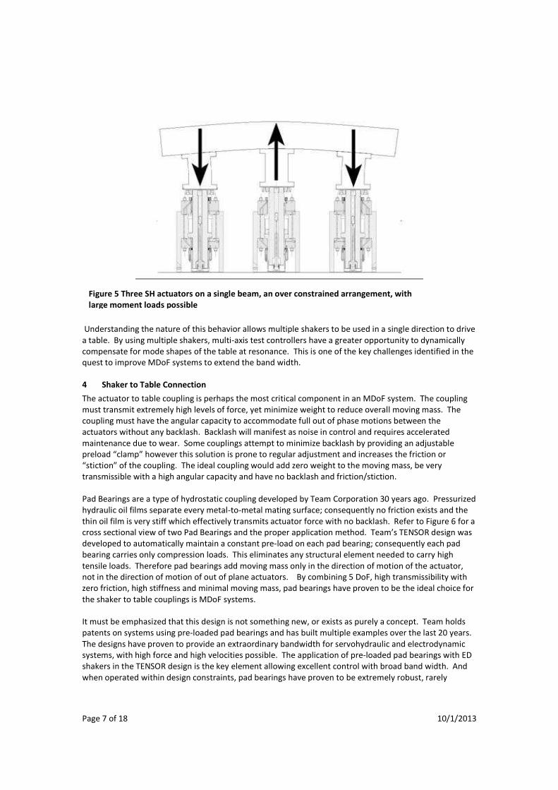
A single actuator produces a single degree of freedom; a minimum of 6 actuators is required to produce
6DoF. Over constraint occurs if more actuators are used to produce the desired motion than are
necessary. The potential to damage the test object, the shaker equipment or both exists in an over
constrained SH system. This can be seen in Figure 5 where three SH actuators are attached to a single
beam. As shown in the drawing, the two outermost SH shakers are retracting, while the middle shaker is
extending. Since the SH shakers are stiff springs, the middle shaker will strongly resist retraction and
consequently very large moment loads are generated. Replace the SH actuators with ED shakers and the
situation changes dramatically. The soft spring characteristic of ED shakers mitigates the potential for
damage as the middle shaker will retract once its force is overcome by the two outermost shakers.
Figure 4 Cartesian coordinate system defining 6DoF
Page 7 of 18 10/1/2013
Understanding the nature of this behavior allows multiple shakers to be used in a single direction to drive
a table. By using multiple shakers, multi-axis test controllers have a greater opportunity to dynamically
compensate for mode shapes of the table at resonance. This is one of the key challenges identified in the
quest to improve MDoF systems to extend the band width.
4 Shaker to Table Connection
The actuator to table coupling is perhaps the most critical component in an MDoF system. The coupling
must transmit extremely high levels of force, yet minimize weight to reduce overall moving mass. The
coupling must have the angular capacity to accommodate full out of phase motions between the
actuators without any backlash. Backlash will manifest as noise in control and requires accelerated
maintenance due to wear. Some couplings attempt to minimize backlash by providing an adjustable
preload “clamp” however this solution is prone to regular adjustment and increases the friction or
“stiction” of the coupling. The ideal coupling would add zero weight to the moving mass, be very
transmissible with a high angular capacity and have no backlash and friction/stiction.
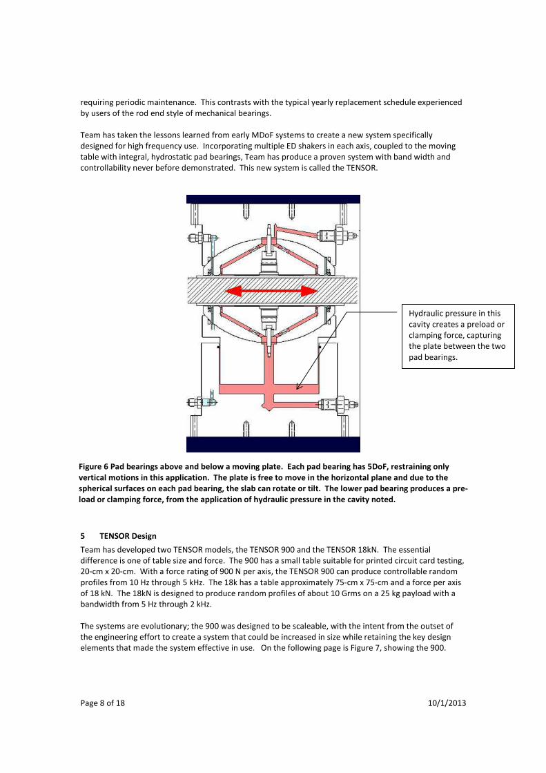
Pad Bearings are a type of hydrostatic coupling developed by Team Corporation 30 years ago. Pressurized
hydraulic oil films separate every metal-to-metal mating surface; consequently no friction exists and the
thin oil film is very stiff which effectively transmits actuator force with no backlash. Refer to Figure 6 for a
cross sectional view of two Pad Bearings and the proper application method. Team’s TENSOR design was
developed to automatically maintain a constant pre-load on each pad bearing; consequently each pad
bearing carries only compression loads. This eliminates any structural element needed to carry high
tensile loads. Therefore pad bearings add moving mass only in the direction of motion of the actuator,
not in the direction of motion of out of plane actuators. By combining 5 DoF, high transmissibility with
zero friction, high stiffness and minimal moving mass, pad bearings have proven to be the ideal choice for
the shaker to table couplings is MDoF systems.
It must be emphasized that this design is not something new, or exists as purely a concept. Team holds
patents on systems using pre-loaded pad bearings and has built multiple examples over the last 20 years.
The designs have proven to provide an extraordinary bandwidth for servohydraulic and electrodynamic
systems, with high force and high velocities possible. The application of pre-loaded pad bearings with ED
shakers in the TENSOR design is the key element allowing excellent control with broad band width. And
when operated within design constraints, pad bearings have proven to be extremely robust, rarely
Figure 5 Three SH actuators on a single beam, an over constrained arrangement, with
large moment loads possible
Page 8 of 18 10/1/2013
requiring periodic maintenance. This contrasts with the typical yearly replacement schedule experienced
by users of the rod end style of mechanical bearings.
Team has taken the lessons learned from early MDoF systems to create a new system specifically
designed for high frequency use. Incorporating multiple ED shakers in each axis, coupled to the moving
table with integral, hydrostatic pad bearings, Team has produce a proven system with band width and
controllability never before demonstrated. This new system is called the TENSOR.
5 TENSOR Design
Team has developed two TENSOR models, the TENSOR 900 and the TENSOR 18kN. The essential
difference is one of table size and force. The 900 has a small table suitable for printed circuit card testing,
20-cm x 20-cm. With a force rating of 900 N per axis, the TENSOR 900 can produce controllable random
profiles from 10 Hz through 5 kHz. The 18k has a table approximately 75-cm x 75-cm and a force per axis
of 18 kN. The 18kN is designed to produce random profiles of about 10 Grms on a 25 kg payload with a
bandwidth from 5 Hz through 2 kHz.
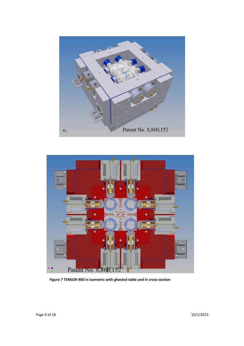
The systems are evolutionary; the 900 was designed to be scaleable, with the intent from the outset of
the engineering effort to create a system that could be increased in size while retaining the key design
elements that made the system effective in use. On the following page is Figure 7, showing the 900.
Figure 6 Pad bearings above and below a moving plate. Each pad bearing has 5DoF, restraining only
vertical motions in this application. The plate is free to move in the horizontal plane and due to the
spherical surfaces on each pad bearing, the slab can rotate or tilt. The lower pad bearing produces a pre-
load or clamping force, from the application of hydraulic pressure in the cavity noted.
Hydraulic pressure in this
cavity creates a preload or
clamping force, capturing
the plate between the two
pad bearings.
Page 9 of 18 10/1/2013
Figure 7 TENSOR-900 in isometric with ghosted table and in cross-section

Page 10 of 18 10/1/2013
5.1 TENSOR 900 Design Features
Two TENSOR 900 systems are presently in use; Sandia National Laboratories received the first unit and the
University of Maryland CALCE consortium has the other. Both units were installed for the express
purpose of validating the design and with the intent to identify design weaknesses, if any. The systems
have proven to reproduce very controllable test profiles with excellent coherence, allowing test engineers
the ability to recreate simultaneous excitation in all translations and rotations. This is the first time
measured field conditions have bee reproducible in the laboratory through the bandwidth required to
excite multiple modes in small, relatively stiff components, such as printed circuit boards, etc. An
example of this controllability, achieved at Sandia, is shown in Figure 8 below.
The design of the 900 incorporates all the various sub-assemblies, including the shaker system, the
hydraulic power supply and the power amplifiers, into a unified cabinet with a single power connection,
to facilitate installation. The resulting effort is shown on the following page in Figures 9 and 10.
The power amplifiers are located to right, with the table located to the left. Embedded within the cabinet
is the hydraulic power supply that provides hydrostatic bearing oil and the flow used for active cooling of
the field and voice coils.
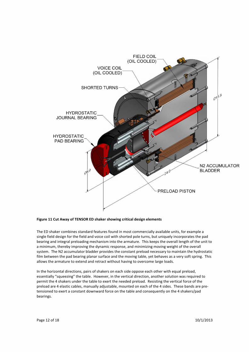
The key feature of the TENSOR design is the custom ED shakers with an integral pad bearing coupling built
into the armature. A cut away view of the shaker is provided in Figure 11, with the important features
labeled for clarity.
Figure 8 Translational control of TENSOR 900 through 2 kHz

Page 11 of 18 10/1/2013
Figure 9 TENSOR 900 System
Figure 10 Close up view of table
Page 12 of 18 10/1/2013
Figure 11 Cut Away of TENSOR ED shaker showing critical design elements
The ED shaker combines standard features found in most commercially available units, for example a
single field design for the field and voice coil with shorted pole turns, but uniquely incorporates the pad
bearing and integral preloading mechanism into the armature. This keeps the overall length of the unit to
a minimum, thereby improving the dynamic response, and minimizing moving weight of the overall
system. The N2 accumulator bladder provides the constant preload necessary to maintain the hydrostatic
film between the pad bearing planar surface and the moving table, yet behaves as a very soft spring. This
allows the armature to extend and retract without having to overcome large loads.
In the horizontal directions, pairs of shakers on each side oppose each other with equal preload,
essentially “squeezing” the table. However, in the vertical direction, another solution was required to
permit the 4 shakers under the table to exert the needed preload. Resisting the vertical force of the
preload are 4 elastic cables, manually adjustable, mounted on each of the 4 sides. These bands are pre-
tensioned to exert a constant downward force on the table and consequently on the 4 shakers/pad
bearings.
Page 13 of 18 10/1/2013
Effective in use, the need to monitor the elastic cables producing the needed vertical preload became
problematic and created an unintended maintenance issue. Another feature of the TENSOR 900 design
that had unintended limitations is the configuration of the table in relation to the top of the cabinet. A
close examination of Figure 10 shows that the table top is below the top level of the cabinet. This creates
test object mounting and instrumentation difficulties. The intent of the design was to bring the force
vectors of the ED shakers as close to the top of the table as possible, to minimize overturning moments.
However, the minor reduction of generated moments is overshadowed by the awkwardness involved in
mounting the test object. Finally, incorporating the amplifiers and hydraulic power supply into the unified
cabinet, while creating a pleasing aesthetic, hampered periodic maintenance and placed the noise and
heat generation devices into the test operator’s direct vicinity. These issues, coupled with the limited
table size and force of the system, are addressed in the TENSOR 18kN design.
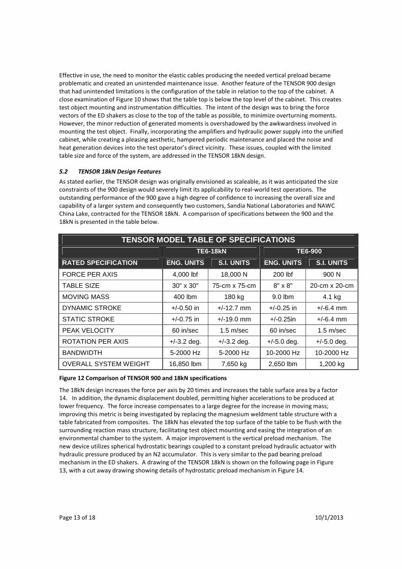
5.2 TENSOR 18kN Design Features
As stated earlier, the TENSOR design was originally envisioned as scaleable, as it was anticipated the size
constraints of the 900 design would severely limit its applicability to real-world test operations. The
outstanding performance of the 900 gave a high degree of confidence to increasing the overall size and
capability of a larger system and consequently two customers, Sandia National Laboratories and NAWC
China Lake, contracted for the TENSOR 18kN. A comparison of specifications between the 900 and the
18kN is presented in the table below.
TENSOR MODEL TABLE OF SPECIFICATIONS TE6-18kN TE6-900
RATED SPECIFICATION ENG. UNITS S.I. UNITS ENG. UNITS S.I. UNITS
FORCE PER AXIS 4,000 lbf 18,000 N 200 lbf 900 N
TABLE SIZE 30" x 30" 75-cm x 75-cm 8" x 8" 20-cm x 20-cm
MOVING MASS 400 lbm 180 kg 9.0 lbm 4.1 kg
DYNAMIC STROKE +/-0.50 in +/-12.7 mm +/-0.25 in +/-6.4 mm
STATIC STROKE +/-0.75 in +/-19.0 mm +/-0.25in +/-6.4 mm
PEAK VELOCITY 60 in/sec 1.5 m/sec 60 in/sec 1.5 m/sec
ROTATION PER AXIS +/-3.2 deg. +/-3.2 deg. +/-5.0 deg. +/-5.0 deg.
BANDWIDTH 5-2000 Hz 5-2000 Hz 10-2000 Hz 10-2000 Hz
OVERALL SYSTEM WEIGHT 16,850 lbm 7,650 kg 2,650 lbm 1,200 kg
Figure 12 Comparison of TENSOR 900 and 18kN specifications
The 18kN design increases the force per axis by 20 times and increases the table surface area by a factor
14. In addition, the dynamic displacement doubled, permitting higher accelerations to be produced at
lower frequency. The force increase compensates to a large degree for the increase in moving mass;
improving this metric is being investigated by replacing the magnesium weldment table structure with a
table fabricated from composites. The 18kN has elevated the top surface of the table to be flush with the
surrounding reaction mass structure, facilitating test object mounting and easing the integration of an
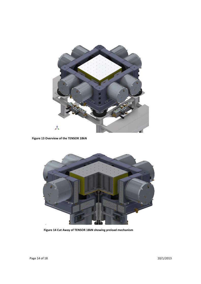
environmental chamber to the system. A major improvement is the vertical preload mechanism. The
new device utilizes spherical hydrostatic bearings coupled to a constant preload hydraulic actuator with
hydraulic pressure produced by an N2 accumulator. This is very similar to the pad bearing preload
mechanism in the ED shakers. A drawing of the TENSOR 18kN is shown on the following page in Figure
13, with a cut away drawing showing details of hydrostatic preload mechanism in Figure 14.
Page 14 of 18 10/1/2013
Figure 13 Overview of the TENSOR 18kN
Figure 14 Cut Away of TENSOR 18kN showing preload mechanism
Page 15 of 18 10/1/2013
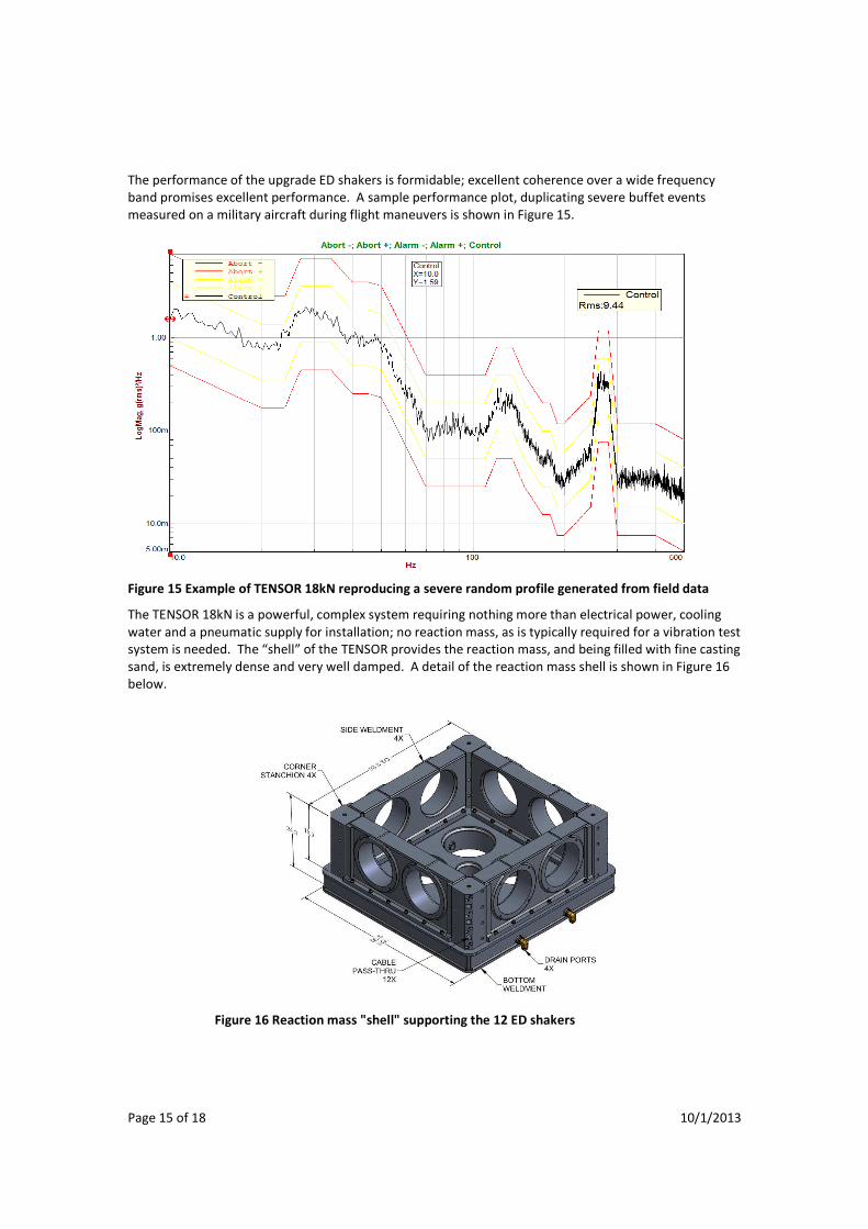
The performance of the upgrade ED shakers is formidable; excellent coherence over a wide frequency
band promises excellent performance. A sample performance plot, duplicating severe buffet events
measured on a military aircraft during flight maneuvers is shown in Figure 15.
Figure 15 Example of TENSOR 18kN reproducing a severe random profile generated from field data
The TENSOR 18kN is a powerful, complex system requiring nothing more than electrical power, cooling
water and a pneumatic supply for installation; no reaction mass, as is typically required for a vibration test
system is needed. The “shell” of the TENSOR provides the reaction mass, and being filled with fine casting
sand, is extremely dense and very well damped. A detail of the reaction mass shell is shown in Figure 16
below.
Figure 16 Reaction mass "shell" supporting the 12 ED shakers
Page 16 of 18 10/1/2013
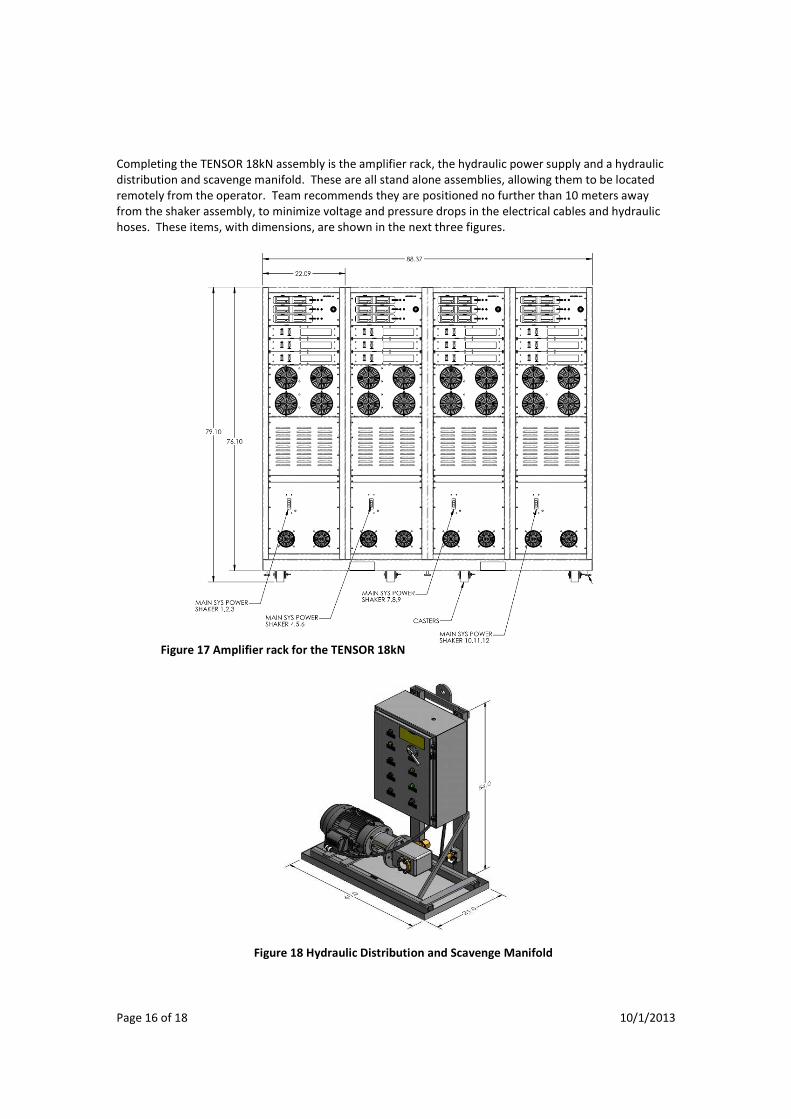
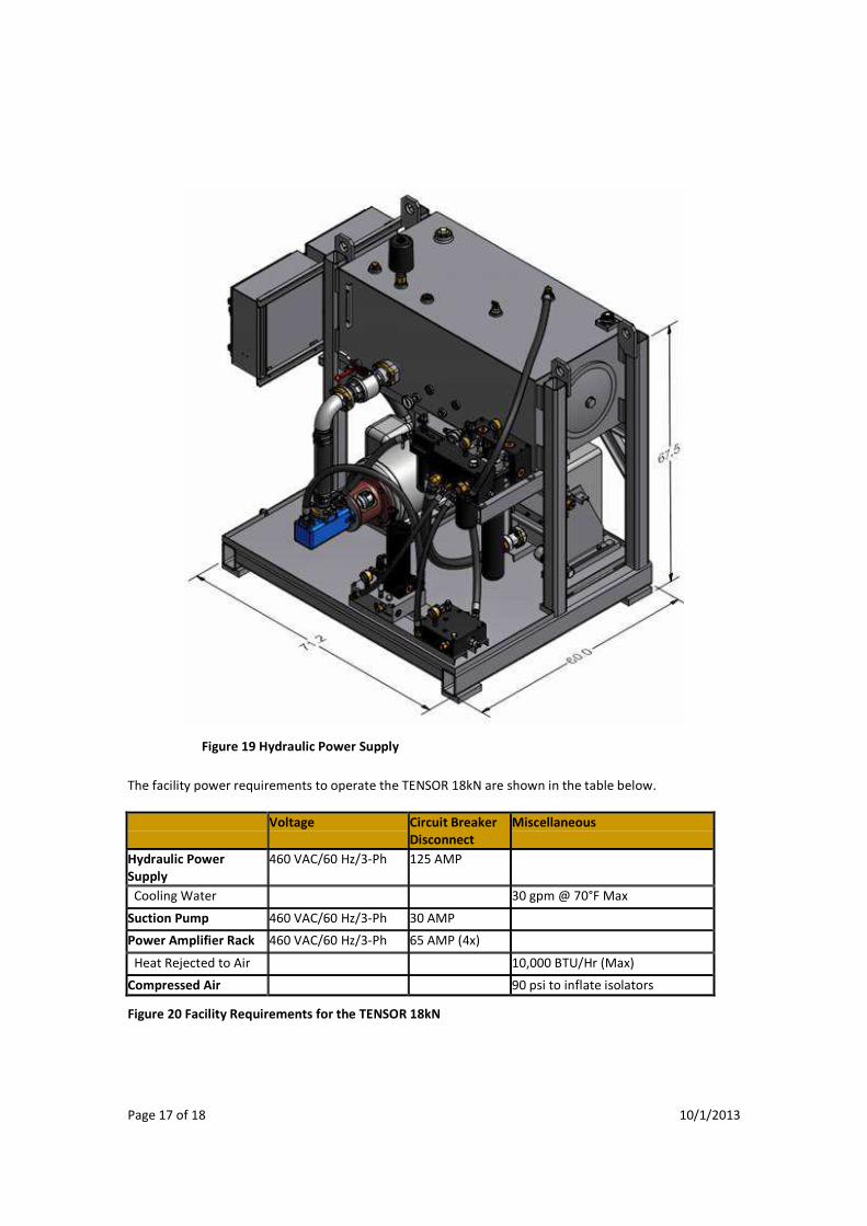
Completing the TENSOR 18kN assembly is the amplifier rack, the hydraulic power supply and a hydraulic
distribution and scavenge manifold. These are all stand alone assemblies, allowing them to be located
remotely from the operator. Team recommends they are positioned no further than 10 meters away
from the shaker assembly, to minimize voltage and pressure drops in the electrical cables and hydraulic
hoses. These items, with dimensions, are shown in the next three figures.
Figure 17 Amplifier rack for the TENSOR 18kN
Figure 18 Hydraulic Distribution and Scavenge Manifold
Page 17 of 18 10/1/2013
The facility power requirements to operate the TENSOR 18kN are shown in the table below.
Voltage Circuit Breaker
Disconnect
Miscellaneous
Hydraulic Power
Supply
460 VAC/60 Hz/3-Ph 125 AMP
Cooling Water 30 gpm @ 70°F Max
Suction Pump 460 VAC/60 Hz/3-Ph 30 AMP
Power Amplifier Rack 460 VAC/60 Hz/3-Ph 65 AMP (4x)
Heat Rejected to Air 10,000 BTU/Hr (Max)
Compressed Air 90 psi to inflate isolators
Figure 20 Facility Requirements for the TENSOR 18kN
Figure 19 Hydraulic Power Supply
Page 18 of 18 10/1/2013
6 Conclusion
Reproducing in the test laboratory operational conditions encountered in the field is widely recognized as
the best means to improve product reliability. However, reliability engineers have been limited to
controllable single axis excitation due to the constraints of available test system designs, or much
abbreviated frequency bands due to performance restrictions of exciters and couplings. The advent of
the TENSOR now offers the ability to reproduce reality, in the laboratory, repeatably and accurately.
The TENSOR family of multi axis vibration test systems is the most capable system currently offered on
the market today, and expects to remain the standard to meet. Independently proven to reproduce
complex waveforms as well as random and swept sine profiles, the TENSOR can generate these outputs in
any combination of linear translations and axial rotations. Coupled with the contemporary multi axis test
controllers available, the TENSOR can recreate virtually any operational environment, limited only by the
system’s displacement, velocity and force. Team Corporation does not manufacture test controllers;
however, at least two companies, Data Physics and Spectral Dynamics, have demonstrated the ability to
effectively control the TENSOR.
The TENSOR is the culmination of decades of development by Team Corporation, incorporating
hydrostatic bearing design, mechanical design and systems configuration derived from literally hundreds
of different vibration test systems manufactured and installed. But these models do not represent the
completion of Team’s efforts. Indeed, a number of design avenues to improve performance, increase
capabilities and extend utility of the TENSOR are anticipated. Team views the TENSOR as a step in the
path to bringing true field operational conditions into every lab.
If you desire further information on the TENSOR, or wish to discuss purpose-built test systems, don’t
hesitate to contact Team Corporation at the address, phone or email provided below:
Team Corporation
11591 Watertank Road
Burlington, WA 98233
USA
(360) 757-8601 main switchboard
www.teamcorporation.com
Recommended