STRESS AND STRAIN RELATIONS
UNIT I
DIRECT OR NORMAL STRESS
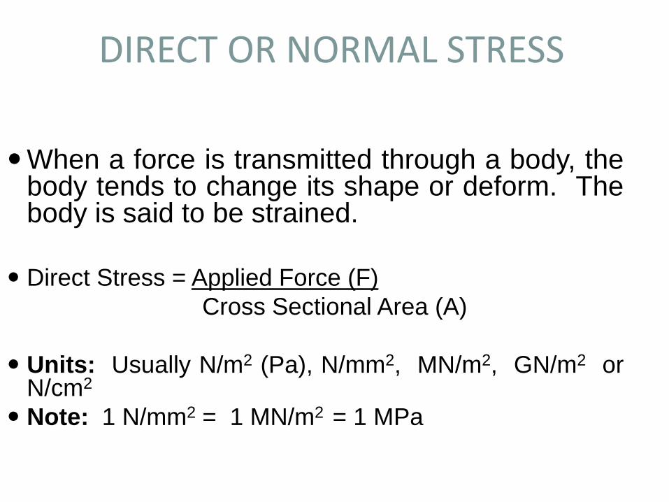
When a force is transmitted through a body, thebody tends to change its shape or deform. Thebody is said to be strained.
Direct Stress = Applied Force (F)
Cross Sectional Area (A)
Units: Usually N/m2 (Pa), N/mm2, MN/m2, GN/m2 orN/cm2
Note: 1 N/mm2 = 1 MN/m2 = 1 MPa

Direct Stress Contd.
• Direct stress may be tensile or
compressive and result from forces
acting perpendicular to the plane of the
cross-section
Tension
Compression

Direct or Normal Strain
• When loads are applied to a body, some deformation will occur
resulting to a change in dimension.
• Consider a bar, subjected to axial tensile loading force, F. If the bar
extension is dl and its original length (before loading) is L, then tensile
strain is:
dl
FF
L
Direct Strain ( ) = Change in LengthOriginal Length
i.e. = dl/L

Direct or Normal Strain Contd.
• As strain is a ratio of lengths, it is dimensionless.
• Similarly, for compression by amount, dl:
Compressive strain = - dl/L
• Note: Strain is positive for an increase in dimension
and negative for a reduction in dimension.

Shear Stress and Shear Strain
• Shear stresses are produced by equal and opposite parallel
forces not in line.
• The forces tend to make one part of the material slide over the
other part.
• Shear stress is tangential to the area over which it acts.

Ultimate Strength
The strength of a material is a measure of thestress that it can take when in use. Theultimate strength is the measured stress atfailure but this is not normally used for designbecause safety factors are required. Thenormal way to define a safety factor is :
stressePermissibl
stressUltimate
loadedwhen stress
failureat stress = factorsafety

Strain
We must also define strain. In engineering this is not ameasure of force but is a measure of the deformationproduced by the influence of stress. For tensile andcompressive loads:
Strain is dimensionless, i.e. it is not measured in metres,killogrammes etc.
For shear loads the strain is defined as the angle This ismeasured in radians
strain = increase in length x
original length L
shear strain shear displacement x
width L

Shear stress and strain
Shear force
Shear Force
Area resisting shear
Shear displacement (x)
Shear strain is angle L

Shear Stress and Shear Strain Contd.
P Q
S R
F
D D’
A B
C C’
L
x
Shear strain is the distortion produced by shear stress on an element
or rectangular block as above. The shear strain, (gamma) is
given as:
= x/L = tan

Shear Stress and Shear Strain Concluded
• For small ,
• Shear strain then becomes the change in
the right angle.
• It is dimensionless and is measured in radians.

Elastic and Plastic deformation
Stress
Strain
Stress
Strain
Permanent Deformation
Elastic deformation Plastic deformation
Modulus of Elasticity
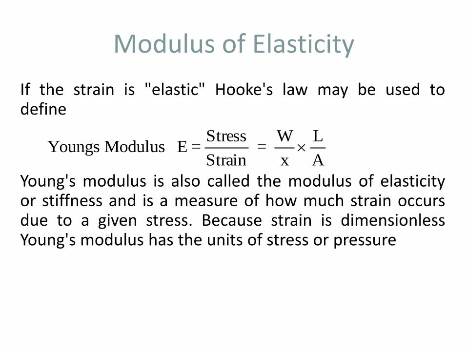
If the strain is "elastic" Hooke's law may be used todefine
Young's modulus is also called the modulus of elasticityor stiffness and is a measure of how much strain occursdue to a given stress. Because strain is dimensionlessYoung's modulus has the units of stress or pressure
A
L
x
W =
Strain
Stress = E Modulus Youngs

How to calculate deflection if the proof stress is applied and then partially removed.
Yield
0.2% proof stress
Stress
Strain0.2%
Plastic
Failures
0.002 s/E
If a sample is loaded up to the 0.2% proof stress and then unloaded to a stress s the strain x = 0.2% + s/E where E is the Young’s modulus

Volumetric Strain
• Hydrostatic stress refers to tensile orcompressive stress in all dimensionswithin or external to a body.
• Hydrostatic stress results in change involume of the material.
• Consider a cube with sides x, y, z. Letdx, dy, and dz represent increase inlength in all directions.
• i.e. new volume = (x + dx) (y + dy) (z +dz)

Volumetric Strain Contd.
• Neglecting products of small quantities:
• New volume = x y z + z y dx + x z dy + x y dz
• Original volume = x y z
• = z y dx + x z dy + x y dz
• Volumetric strain, = z y dx + x z dy + x y dz
x y z
• = dx/x + dy/y + dz/z
V v
v
v x y z
Elasticity and Hooke’s Law
• All solid materials deform when they are
stressed, and as stress is increased,
deformation also increases.
• If a material returns to its original size and
shape on removal of load causing
deformation, it is said to be elastic.
• If the stress is steadily increased, a point is
reached when, after the removal of load, not
all the induced strain is removed.
• This is called the elastic limit.

Hooke’s Law
• States that providing the limit of proportionality ofa material is not exceeded, the stress is directlyproportional to the strain produced.
• If a graph of stress and strain is plotted as load isgradually applied, the first portion of the graph willbe a straight line.
• The slope of this line is the constant ofproportionality called modulus of Elasticity, E orYoung’s Modulus.
• It is a measure of the stiffness of a material.

Hooke’s Law
Modulus of Elasticity, E = Direct stress
Direct strain
Also: For Shear stress: Modulus of rigidity or shear modulus, G = Shear stress
Shear strain
Also: Volumetric strain, is proportional to hydrostatic stress, within the
elastic range
i.e. : called bulk modulus.
v
/ v K

Stress-Strain Relations of Mild Steel

Thermal Strain Contd.
As in the case of lateral strains, thermal strains
do not induce stresses unless they are constrained.
The total strain in a body experiencing thermal stress
may be divided into two components:
Strain due to stress, and
That due to temperature, T .
Thus: = + T
=
E
T
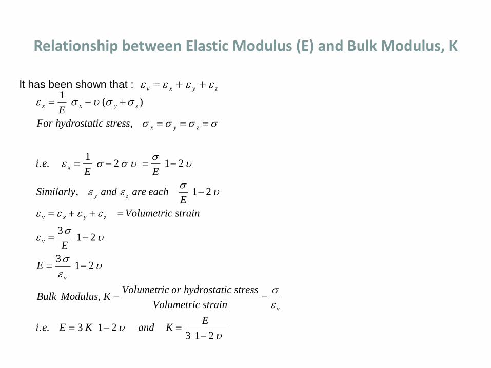
Relationship between Elastic Modulus (E) and Bulk Modulus, K
It has been shown that : v x y z
x x y z
x y z
x
y z
v x y z
v
v
v
E
For hydrostatic stress
i eE E
Similarly and are eachE
Volumetric strain
E
E
Bulk Modulus KVolumetric or hydrostatic stress
Volumetric strain
i e E K and KE
1
12 1 2
1 2
31 2
31 2
3 1 23 1 2
( )
,
. .
,
,
. .

Compound Bars
A compound bar is one comprising two or more parallel elements, of different materials,
which are fixed together at their end. The compound bar may be loaded in tension or
compression.
1 2
F F
2
Section through a typical compound bar consisting of a circular bar (1) surrounded by a
tube (2)
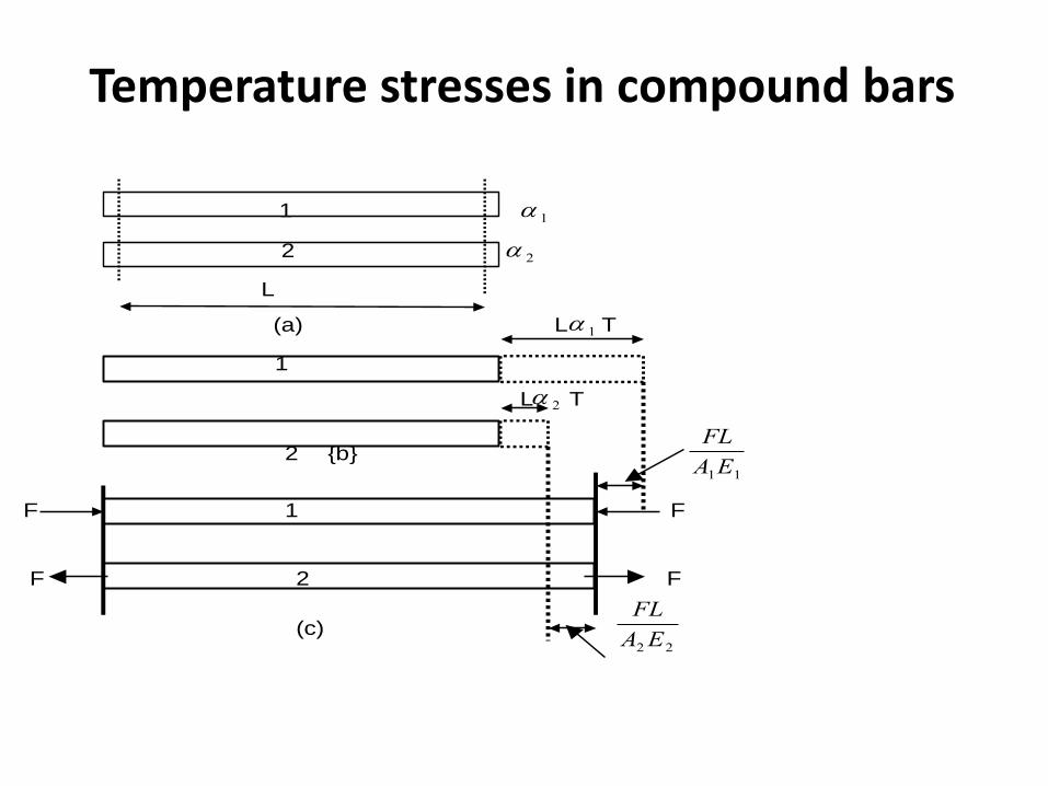
Temperature stresses in compound bars
1 1
2 2
L
(a) L 1 T
1
L 2 T
2 {b} FL
A E1 1
F 1 F
F 2 F
(c) FL
A E2 2

Temperature Stresses Contd.
Free expansions in bars (1) and (2) are L T and L T 1 2 respectively.
Due to end fixing force, F: the decrease in length of bar (1) is
FL
A E1 1
and the increase in length of (2) is FL
A E2 2
.
At Equilibrium:
L TFL
A EL T
FL
A E
i e FA E A E
T
i e AA E A E
E E A AT
T A E E
A E A E
T A E E
A E A E
1
1 1
2
2 2
1 1 2 2
1 2
1 12 2 1 1
1 2 1 2
1 2
11 2 2 1 2
1 1 2 2
21 2 1 1 2
1 1 2 2
1 1
LNM
OQP
. . [ ] ( )
. . ( )
( )
( )
Note: As a result of Force, F, bar (1) will be in compression while (2) will be in tension.
1 1
2 2
L
(a) L 1 T
1
L 2 T
2 {b} FL
A E1 1
F 1 F
F 2 F
(c) FL
A E2 2
Recommended


![Kurs i PPT-arkivikava.itumkunde.no/ikava/vedlegg/PPT-kurs[2].pdfReferat m.m. styre, råd, nemnder, utvalg Interkommunalt arkiv i Vest-Agder IKS (IKAVA) Kassasjon Som basisår skal](https://img.dokumen.tips/doc/110x75/5e4096a1b94fcc24c569b2ce/kurs-i-ppt-2pdf-referat-mm-styre-rd-nemnder-utvalg-interkommunalt-arkiv.jpg)
![[PPT]PowerPoint-presentasjon - Norsk Industri · Web viewTemplate by addpoint.no ... Prosjektets formål Prosjektet NORSOK-analyse har hatt som formål å utarbeide NORSOK-eiernes](https://img.dokumen.tips/doc/110x75/5b0071937f8b9a6a2e8ca402/pptpowerpoint-presentasjon-norsk-industri-viewtemplate-by-addpointno-prosjektets.jpg)