SKF TKTI 21 & 31
Instructions for use
2 SKF TKTI 21 & 31
EC Declaration of conformity ....................................................................................3
Safety recommendations ..........................................................................................4
1. Introduction .....................................................................................................5
2. Overview .....................................................................................................62.1 Case Content .................................................................................................................. 62.2 Camera Overview .......................................................................................................... 7
3. Getting Started ................................................................................................83.1 Battery ............................................................................................................................ 8 3.1.1 Battery Installation and Replacement ........................................................... 8 3.1.2 Charging the Battery ....................................................................................... 9 3.1.3 Battery safety and usage ................................................................................ 93.2 Switching On the Camera ...........................................................................................103.3 Focusing ........................................................................................................................103.4 Buttons ..........................................................................................................................11 3.4.1 On/Off Button .................................................................................................12 3.4.2 A button ...........................................................................................................12 3.4.3 S button ...........................................................................................................14 3.4.4 C button ...........................................................................................................14 3.4.5 Menu/Okay button and navigation pad ......................................................15
4. Using the Camera ...........................................................................................164.1 Screen elements ..........................................................................................................164.2 Menu functions ............................................................................................................16 4.2.1 Measurement cursors ...................................................................................16 4.2.2 Level/Span ......................................................................................................18 4.2.3 Setup ................................................................................................................194.3 Measuring .....................................................................................................................21 4.3.1 Laser pointer...................................................................................................21 4.3.2 Colour palettes ................................................................................................21 4.3.3 Emissivity .........................................................................................................22 4.3.4 Field of view ....................................................................................................23 4.3.5 Temperature measurement ..........................................................................24 4.3.6 Alarms and Isotherms ...................................................................................264.4 Taking pictures .............................................................................................................27 4.4.1 Freeze and Save images ...............................................................................27 4.4.2 Add a voice Comment ...................................................................................27 4.4.3 View saved images.........................................................................................28 4.4.4 Settings for saved images ............................................................................28
5. Technical Speciications ..................................................................................31
6. Appendix .......................................................................................................346.1 Troubleshooting ...........................................................................................................346.2 Emissivity table ............................................................................................................35
Table of contents
Original instructions
3SKF TKTI 21 & 31
EC Declaration of conformity
We, SKF Maintenance Products Kelvinbaan 16 3439 MT Nieuwegein The Netherlands
herewith declare that the following products:
SKF Thermal Camera TKTI 21TKTI 31
has been designed and manufactured in accordance with:EMC DIRECTIVE 2004/108/EC as outlined in the harmonized norm forEN61326-1:2006 Class AEN61326-2-2:2006IEC61000-4-2:2008IEC61000-4-3:2006FCC Part 15 Subpart B
The laser is classiied in accordance to the 21CFR 1040.10 and 1040.11 except for deviations pursuant to laser notice No. 50 dated June 24th 2007 and complies with IEC/EN 60825-1.
EUROPEAN ROHS DIRECTIVE 2011/65/EU
Nieuwegein, The Netherlands, September 2013
Sébastien DavidManager Product Development and Quality
4 SKF TKTI 21 & 31
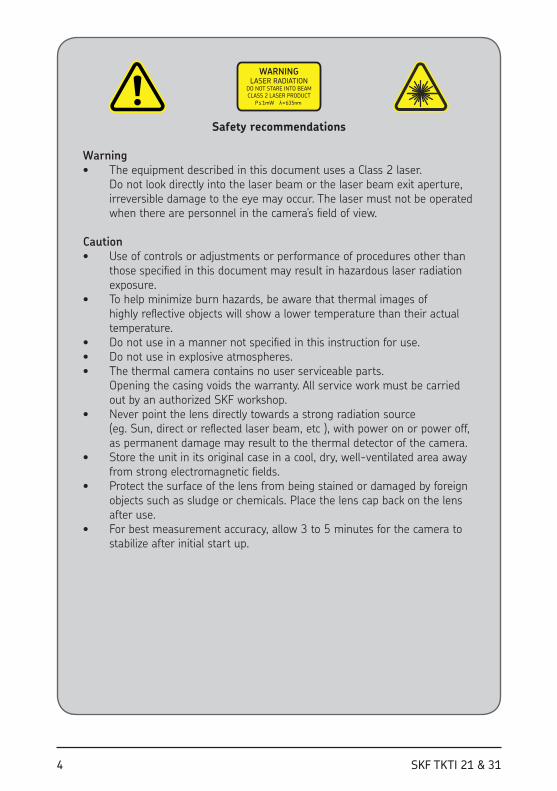
Safety recommendations
Warning• The equipment described in this document uses a Class 2 laser.
Do not look directly into the laser beam or the laser beam exit aperture, irreversible damage to the eye may occur. The laser must not be operated when there are personnel in the camera’s ield of view.
Caution• Use of controls or adjustments or performance of procedures other than
those speciied in this document may result in hazardous laser radiation exposure.
• To help minimize burn hazards, be aware that thermal images of highly relective objects will show a lower temperature than their actual temperature.
• Do not use in a manner not speciied in this instruction for use.• Do not use in explosive atmospheres.• The thermal camera contains no user serviceable parts.
Opening the casing voids the warranty. All service work must be carried out by an authorized SKF workshop.
• Never point the lens directly towards a strong radiation source (eg. Sun, direct or relected laser beam, etc ), with power on or power off, as permanent damage may result to the thermal detector of the camera.
• Store the unit in its original case in a cool, dry, well-ventilated area away from strong electromagnetic ields.
• Protect the surface of the lens from being stained or damaged by foreign objects such as sludge or chemicals. Place the lens cap back on the lens after use.
• For best measurement accuracy, allow 3 to 5 minutes for the camera to stabilize after initial start up.
WARNING
LASER RADIATION
DO NOT STARE INTO BEAM
CLASS 2 LASER PRODUCT
P ≤ 1mW l = 635nm
5SKF TKTI 21 & 31
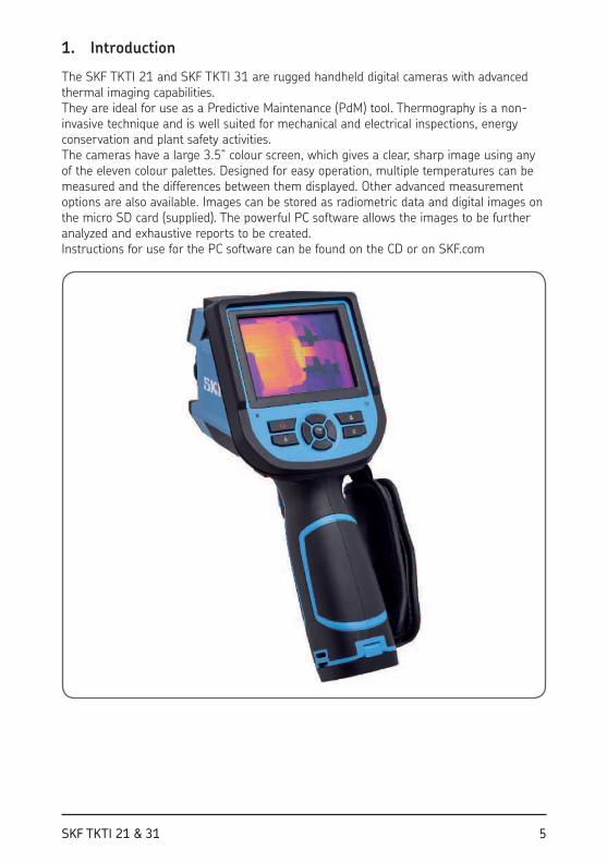
1 . Introduction
The SKF TKTI 21 and SKF TKTI 31 are rugged handheld digital cameras with advanced thermal imaging capabilities. They are ideal for use as a Predictive Maintenance (PdM) tool. Thermography is a non-invasive technique and is well suited for mechanical and electrical inspections, energy conservation and plant safety activities. The cameras have a large 3.5” colour screen, which gives a clear, sharp image using any of the eleven colour palettes. Designed for easy operation, multiple temperatures can be measured and the differences between them displayed. Other advanced measurement options are also available. Images can be stored as radiometric data and digital images on the micro SD card (supplied). The powerful PC software allows the images to be further analyzed and exhaustive reports to be created. Instructions for use for the PC software can be found on the CD or on SKF.com
6 SKF TKTI 21 & 31
2. Overview
2.1 Case Content
12 6
4 37 58
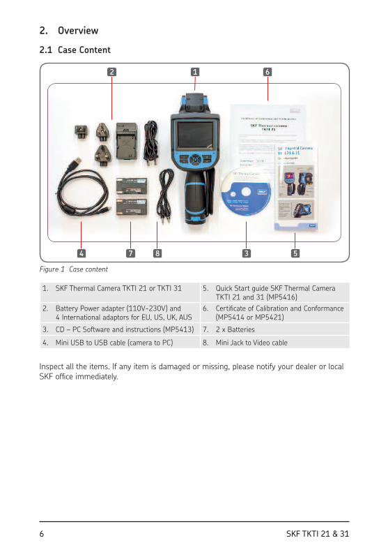
Figure 1 Case content
1. SKF Thermal Camera TKTI 21 or TKTI 31 5. Quick Start guide SKF Thermal Camera TKTI 21 and 31 (MP5416)
2. Battery Power adapter (110V-230V) and 4 International adaptors for EU, US, UK, AUS
6. Certiicate of Calibration and Conformance (MP5414 or MP5421)
3. CD – PC Software and instructions (MP5413) 7. 2 x Batteries
4. Mini USB to USB cable (camera to PC) 8. Mini Jack to Video cable
Inspect all the items. If any item is damaged or missing, please notify your dealer or local SKF ofice immediately.
7SKF TKTI 21 & 31
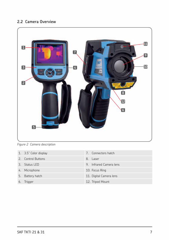
2.2 Camera Overview
1
3
2
4
5
7
10
9
11
8
12
6
Figure 2 Camera description
1. 3.5” Color display 7. Connectors hatch
2. Control Buttons 8. Laser
3. Status LED 9. Infrared Camera lens
4. Microphone 10. Focus Ring
5. Battery hatch 11. Digital Camera lens
6. Trigger 12. Tripod Mount
8 SKF TKTI 21 & 31
1
2
3
4
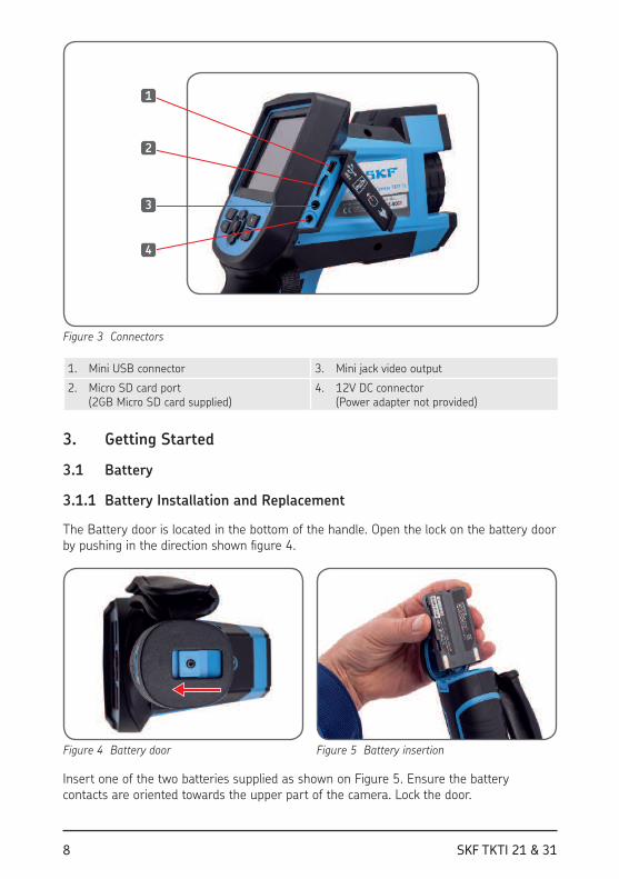
Figure 3 Connectors
1. Mini USB connector 3. Mini jack video output
2. Micro SD card port (2GB Micro SD card supplied)
4. 12V DC connector (Power adapter not provided)
3. Getting Started
3.1 Battery
3.1.1 Battery Installation and Replacement
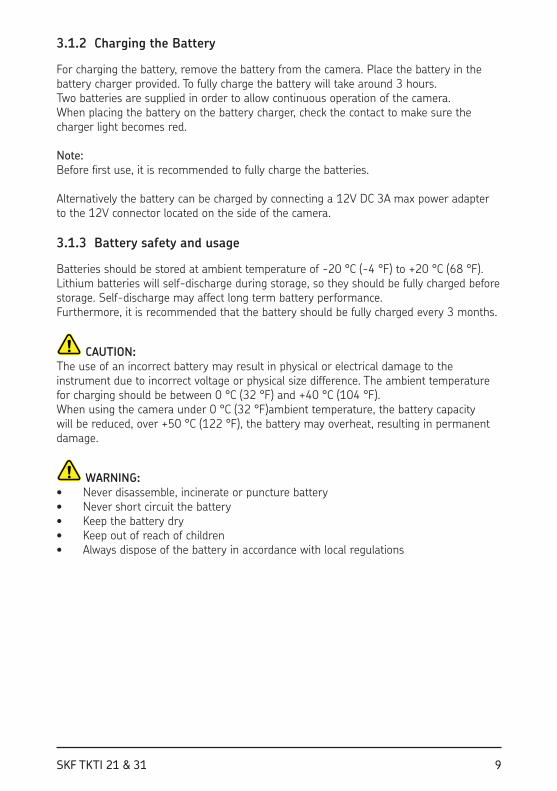
The Battery door is located in the bottom of the handle. Open the lock on the battery door by pushing in the direction shown i gure 4.
Figure 4 Battery door Figure 5 Battery insertion
Insert one of the two batteries supplied as shown on Figure 5. Ensure the battery contacts are oriented towards the upper part of the camera. Lock the door.
9SKF TKTI 21 & 31
3.1.2 Charging the Battery
For charging the battery, remove the battery from the camera. Place the battery in the battery charger provided. To fully charge the battery will take around 3 hours.Two batteries are supplied in order to allow continuous operation of the camera.When placing the battery on the battery charger, check the contact to make sure the charger light becomes red.
Note: Before irst use, it is recommended to fully charge the batteries.
Alternatively the battery can be charged by connecting a 12V DC 3A max power adapter to the 12V connector located on the side of the camera.
3.1.3 Battery safety and usage
Batteries should be stored at ambient temperature of -20 °C (-4 °F) to +20 °C (68 °F). Lithium batteries will self-discharge during storage, so they should be fully charged before storage. Self-discharge may affect long term battery performance. Furthermore, it is recommended that the battery should be fully charged every 3 months.
CAUTION:The use of an incorrect battery may result in physical or electrical damage to the instrument due to incorrect voltage or physical size difference. The ambient temperature for charging should be between 0 °C (32 °F) and +40 °C (104 °F). When using the camera under 0 °C (32 °F)ambient temperature, the battery capacity will be reduced, over +50 °C (122 °F), the battery may overheat, resulting in permanent damage.
WARNING: • Never disassemble, incinerate or puncture battery• Never short circuit the battery• Keep the battery dry• Keep out of reach of children• Always dispose of the battery in accordance with local regulations
10 SKF TKTI 21 & 31
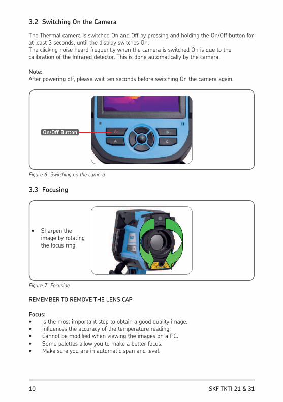
3.2 Switching On the Camera
The Thermal camera is switched On and Off by pressing and holding the On/Off button for at least 3 seconds, until the display switches On.The clicking noise heard frequently when the camera is switched On is due to the calibration of the Infrared detector. This is done automatically by the camera.
Note: After powering off, please wait ten seconds before switching On the camera again.
On/Off Button
Figure 6 Switching on the camera
3.3 Focusing
• Sharpen the image by rotating the focus ring
Figure 7 Focusing
REMEMBER TO REMOVE THE LENS CAP
Focus:• Is the most important step to obtain a good quality image.• Inl uences the accuracy of the temperature reading.• Cannot be modii ed when viewing the images on a PC.• Some palettes allow you to make a better focus. • Make sure you are in automatic span and level.
11SKF TKTI 21 & 31
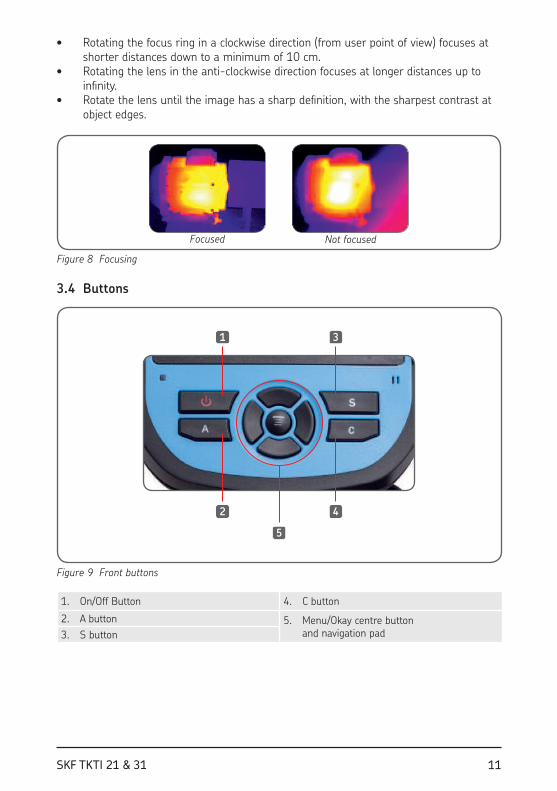
• Rotating the focus ring in a clockwise direction (from user point of view) focuses at shorter distances down to a minimum of 10 cm.
• Rotating the lens in the anti-clockwise direction focuses at longer distances up to ini nity.
• Rotate the lens until the image has a sharp dei nition, with the sharpest contrast at object edges.
Focused Not focused
Figure 8 Focusing
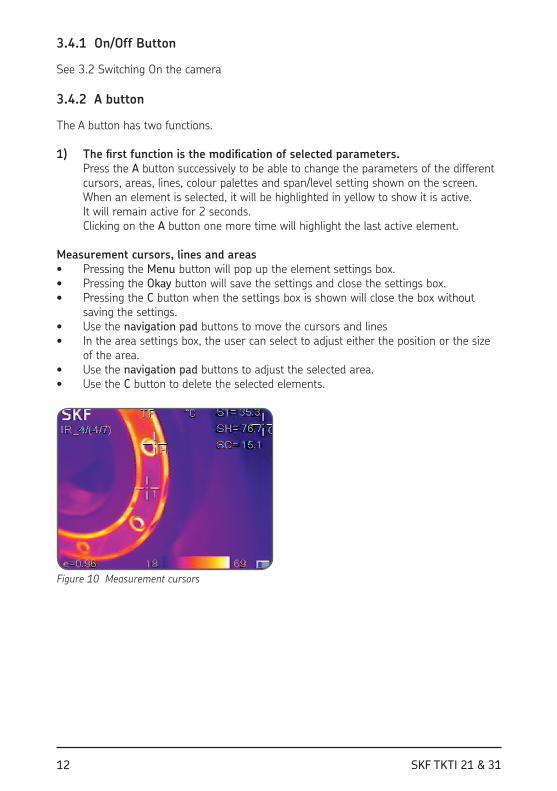
3.4 Buttons
1
2
3
4
5
Figure 9 Front buttons
1. On/Off Button 4. C button
2. A button 5. Menu/Okay centre button and navigation pad3. S button
12 SKF TKTI 21 & 31
3.4.1 On/Off Button
See 3.2 Switching On the camera
3.4.2 A button
The A button has two functions.
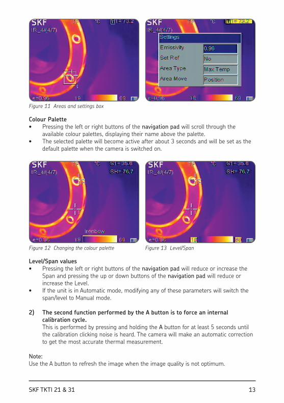
1) The irst function is the modiication of selected parameters. Press the A button successively to be able to change the parameters of the different cursors, areas, lines, colour palettes and span/level setting shown on the screen. When an element is selected, it will be highlighted in yellow to show it is active. It will remain active for 2 seconds. Clicking on the A button one more time will highlight the last active element.
Measurement cursors, lines and areas• Pressing the Menu button will pop up the element settings box.• Pressing the Okay button will save the settings and close the settings box.• Pressing the C button when the settings box is shown will close the box without
saving the settings.• Use the navigation pad buttons to move the cursors and lines • In the area settings box, the user can select to adjust either the position or the size
of the area. • Use the navigation pad buttons to adjust the selected area.• Use the C button to delete the selected elements.
Figure 10 Measurement cursors
13SKF TKTI 21 & 31
Figure 11 Areas and settings box
Colour Palette• Pressing the left or right buttons of the navigation pad will scroll through the
available colour palettes, displaying their name above the palette. • The selected palette will become active after about 3 seconds and will be set as the
default palette when the camera is switched on.
Figure 12 Changing the colour palette Figure 13 Level/Span
Level/Span values• Pressing the left or right buttons of the navigation pad will reduce or increase the
Span and pressing the up or down buttons of the navigation pad will reduce or increase the Level.
• If the unit is in Automatic mode, modifying any of these parameters will switch the span/level to Manual mode.
2) The second function performed by the A button is to force an internal calibration cycle. This is performed by pressing and holding the A button for at least 5 seconds until the calibration clicking noise is heard. The camera will make an automatic correction to get the most accurate thermal measurement.
Note: Use the A button to refresh the image when the image quality is not optimum.

14 SKF TKTI 21 & 31
3.4.3 S button
The S button will allow freezing and viewing the infrared or digital image and save these images.• Pressing the S button once will freeze the image. • Pressing the Okay button will save the thermal and/or visual image.
If Voice recording is enabled, a voice comment dialog box will be displayed.• Press the C button or select the box on the right to return to real-time
measurement.
Figure 14 Saving an infrared image
3.4.4 C button
• Pressing the C button cancels the present operation when browsing in a Menu. • Pressing the C button when an image is frozen or being viewed from the memory
will return to real-time measurement.• When not browsing in a Menu or editing a setting, pressing and releasing the C
button will switch between the thermal image and the visible camera image.• When a parameter is selected, such as a measurement cursor, line or area, pressing
the C button will delete the highlighted cursor, line or area.
15SKF TKTI 21 & 31
3.4.5 Menu/Okay button and navigation pad
The buttons include Up, Down, Left, Right and Menu/Okay (centre). The functions vary with operation mode.• In a Menu, it is used for menu selection. Up and Down buttons are for browsing
vertically. Left and Right keys are for different levels menu operation. Okay button (centre) is to activate the menu and conirm the choice.
• In Infrared Image mode, pressing the Up or Down buttons will activate X2 digital zoom. The screen will display “X2” in the upper left corner. Press Up or Down button again to return to the original image.
• In Spot Measurement editing mode (activated immediately after adding a spot or by selecting via the A button), press the Menu button to pop up the attribute box. Press the navigation pad to move the spot location.
• In line temperature measurement editing mode (activated immediately after adding a line or by selecting via the A button), press the Menu button to pop up the attribute box.
• In area measurement editing mode (activated immediately after adding an area or by selecting via the A key), press the Menu button to pop up the attribute box. Select in the attribute box the parameter to be edited, either size or position.
16 SKF TKTI 21 & 31
4. Using the Camera
4.1 Screen elements
1
2
4
3
5
10
13 13
11
6
7 8
12
9
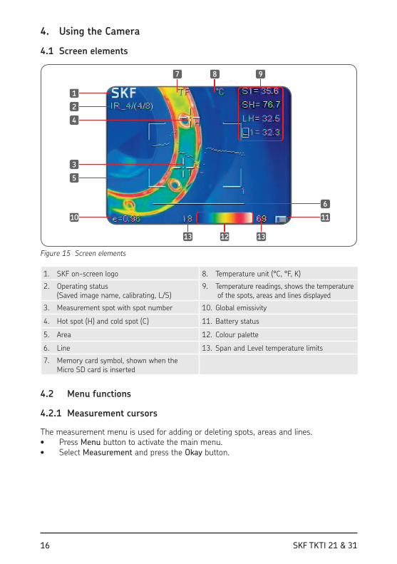
Figure 15 Screen elements
1. SKF on-screen logo 8. Temperature unit (°C, °F, K)
2. Operating status (Saved image name, calibrating, L/S)
9. Temperature readings, shows the temperature of the spots, areas and lines displayed
3. Measurement spot with spot number 10. Global emissivity
4. Hot spot (H) and cold spot (C) 11. Battery status
5. Area 12. Colour palette
6. Line 13. Span and Level temperature limits
7. Memory card symbol, shown when the Micro SD card is inserted
4.2 Menu functions
4.2.1 Measurement cursors
The measurement menu is used for adding or deleting spots, areas and lines. • Press Menu button to activate the main menu. • Select Measurement and press the Okay button.
1
2
4
3
5
10
13 13
11
6
7 8
12
9
17SKF TKTI 21 & 31
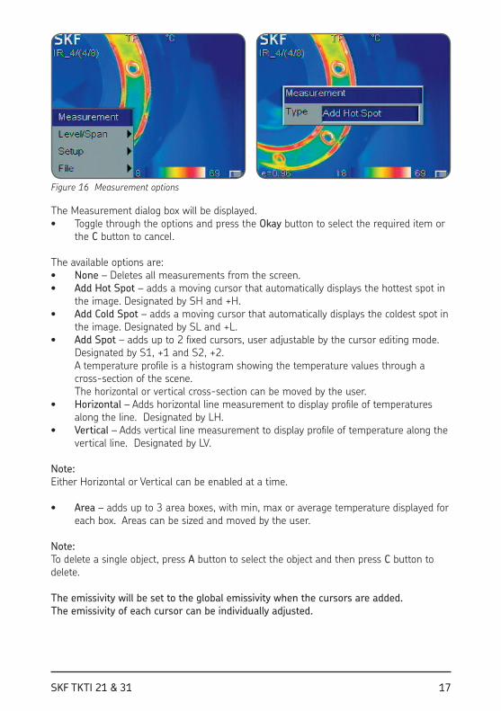
Figure 16 Measurement options
The Measurement dialog box will be displayed. • Toggle through the options and press the Okay button to select the required item or
the C button to cancel.
The available options are:• None – Deletes all measurements from the screen.• Add Hot Spot – adds a moving cursor that automatically displays the hottest spot in
the image. Designated by SH and +H.• Add Cold Spot – adds a moving cursor that automatically displays the coldest spot in
the image. Designated by SL and +L.• Add Spot – adds up to 2 ixed cursors, user adjustable by the cursor editing mode.
Designated by S1, +1 and S2, +2. A temperature proile is a histogram showing the temperature values through a cross-section of the scene. The horizontal or vertical cross-section can be moved by the user.
• Horizontal – Adds horizontal line measurement to display proile of temperatures along the line. Designated by LH.
• Vertical – Adds vertical line measurement to display proile of temperature along the vertical line. Designated by LV.
Note: Either Horizontal or Vertical can be enabled at a time.
• Area – adds up to 3 area boxes, with min, max or average temperature displayed for each box. Areas can be sized and moved by the user.
Note: To delete a single object, press A button to select the object and then press C button to delete.
The emissivity will be set to the global emissivity when the cursors are added.The emissivity of each cursor can be individually adjusted.
18 SKF TKTI 21 & 31
4.2.2 Level/Span
The span is deined by the minimum and maximum temperatures on the scale on the bottom side of the screen. A wider span will give you less thermal details, whereas a narrower span will give you more thermal details but also increases the noise in the image.You can adjust its position within the range, this is the level setting. By adjusting the temperature and colour corresponding relation, users can observe enhanced image quality and easily ind and analyze thermal fault.
There are two operational modes available Automatic or Manual.• In Auto mode, the camera automatically adjusts the image to allow for the highest
and lowest temperature in the scene. This is useful when starting the camera and switching to different parts of a scene.
• In Manual mode, the user deines the range of temperatures to be displayed. Manual setting is useful when the user wants to examine speciic parts of the image. In a ixed temperature range, anomalies or discrepancies can be precisely highlighted.
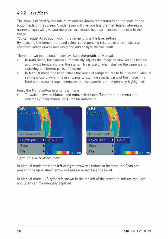
Press the Menu button to enter the menu• To switch between Manual and Auto, select Level/Span from the menu and
validate L/S? for manual or Auto? for automatic.
Figure 17 Auto or Manual mode
In Manual mode press the left or right arrow will reduce or increase the Span and pressing the up or down arrow will reduce or increase the Level.
In Manual mode, L/S symbol is shown in the top left of the screen to indicate the Level and Span can me manually adjusted.
19SKF TKTI 21 & 31
4.2.3 Setup
Access the setup menus by pressing the Menu button and select Setup.
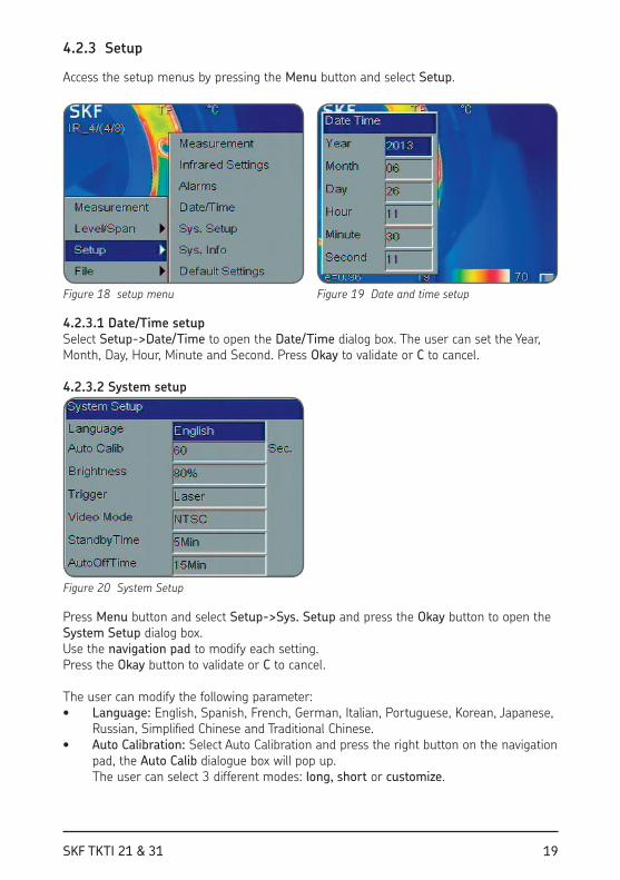
Figure 18 setup menu Figure 19 Date and time setup
4.2.3.1 Date/Time setupSelect Setup->Date/Time to open the Date/Time dialog box. The user can set the Year, Month, Day, Hour, Minute and Second. Press Okay to validate or C to cancel.
4.2.3.2 System setup
Figure 20 System Setup
Press Menu button and select Setup->Sys. Setup and press the Okay button to open the System Setup dialog box. Use the navigation pad to modify each setting.Press the Okay button to validate or C to cancel.
The user can modify the following parameter:• Language: English, Spanish, French, German, Italian, Portuguese, Korean, Japanese,
Russian, Simpliied Chinese and Traditional Chinese.• Auto Calibration: Select Auto Calibration and press the right button on the navigation
pad, the Auto Calib dialogue box will pop up. The user can select 3 different modes: long, short or customize.
20 SKF TKTI 21 & 31
Customize allows the user to set the time interval for the automatic calibration. The range varies from 0, which means Off and 30 to 600 seconds with 1 second increments. Auto calibration is used to improve image quality and measurement accuracy during use.
Note: Calibration can be forced manually by pressing the A button at least 5 seconds until a clicking noise is heard.
• LCD Brightness: The user can select the brightness of LCD display with choices being 20, 40, 60 80 and 100%.
• Trigger: The user can deine the function given to the trigger • Laser (default): The trigger operates the laser - Spot Temp: Adds and deletes the spot Measurement number 1 - Area Temp: Adds and deletes the Area Measurement number 1 - Save key: The trigger will be used to save images - IR/CCD: Switches between IR image and digital visual image.• Video Mode: Select PAL or NTSC video output.• Standby Time: Select the camera standby time from None, 2, 5, 10 or 15 minutes.
When no button is pressed during the set period of time, the camera will turn the display off automatically, to extend the battery life. Press any key except the power key to reactivate the screen. If set to None, the function is disabled.
• AutoOffTime: Select None, 2, 5, 10 or 15 minutes. When no button is pressed during the set period of time, the camera will switch off automatically to extend the battery life. If set to None, the function is disabled. When StandbyTime is enabled, AutoOffTime will start calculating from StandbyTime.
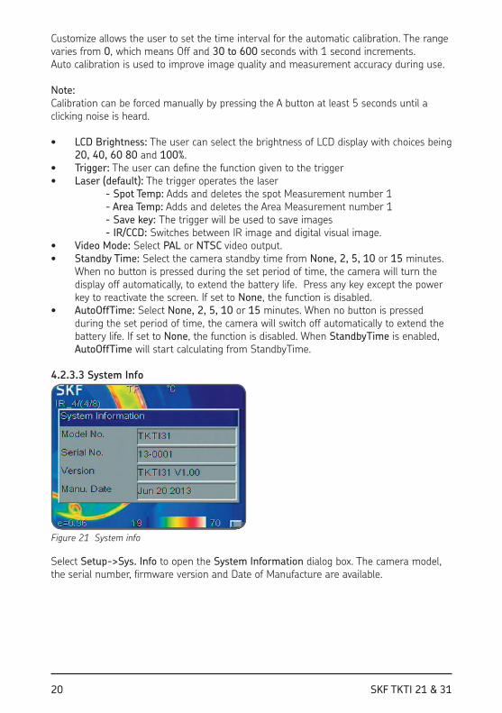
4.2.3.3 System Info
Figure 21 System info
Select Setup->Sys. Info to open the System Information dialog box. The camera model, the serial number, irmware version and Date of Manufacture are available.
21SKF TKTI 21 & 31
4.2.3.4 Factory DefaultSelect Setup->Default to open the Default dialog box. Press the Okay button to reset the settings to the factory default. Press the C button to cancel the reset operation.
Note: The default function will delete all parameters deined by the user.
Note: Restoring Default settings will NOT delete the images stored on the micro SD memory card.
4.3 Measuring
4.3.1 Laser pointer
The laser pointer is used to illuminate and identify features in the image.• Press the trigger to switch On the laser. • Release the trigger to switch Off the laser.
The laser is aligned to objects at a 2 meters distance.
Note: The user can choose to assign other functions to the trigger, in that case the trigger will not operate the laser.
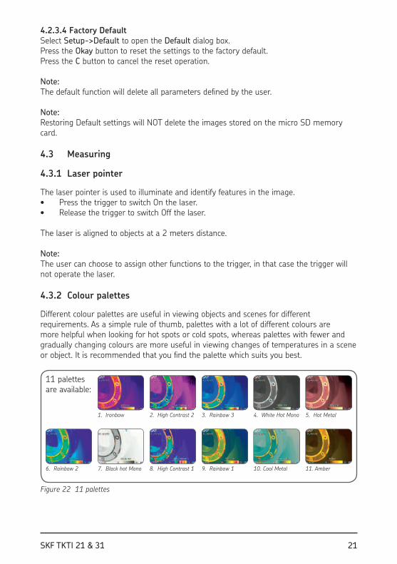
4.3.2 Colour palettes
Different colour palettes are useful in viewing objects and scenes for different requirements. As a simple rule of thumb, palettes with a lot of different colours are more helpful when looking for hot spots or cold spots, whereas palettes with fewer and gradually changing colours are more useful in viewing changes of temperatures in a scene or object. It is recommended that you ind the palette which suits you best.
11 palettes are available:
1. Ironbow 2. High Contrast 2 3. Rainbow 3 4. White Hot Mono 5. Hot Metal
6. Rainbow 2 7. Black hot Mono 8. High Contrast 1 9. Rainbow 1 10. Cool Metal 11. Amber
Figure 22 11 palettes

22 SKF TKTI 21 & 31
4.3.3 Emissivity
Different surfaces can radiate different amounts of infrared energy at the same temperature. This difference in temperature measurement can be corrected by setting the emissivity value.The amount of infrared radiation emitted by a surface depends on both its temperature and its emissivity. Surfaces that are good relectors (e.g. polished metal) are poor emitters, and surfaces that are good emitters (e.g. human skin) are poor relectors. A black body is deined as an object that absorbs all the radiations falling on it and it is also a perfect emitter of radiation.The emissivity of a surface (usually written ε) is the ratio of the energy radiated by that surface to the energy radiated by a black body at the same temperature. For accurate temperature measurements, the emissivity of the surface being measured must be entered into the camera. This is done by entering a number in the range from 0.10 (for polished chromium) to 1.00 (for a black body). An emissivity lookup table is provided, which lists the emissivities of a range of common materials. It is not recommended to use the camera on surfaces with an emissivity below 0.7.The global emissivity can be set via the Adjustment menu.
Select Setup->Adjustment to open the Adjustment dialog box.
Figure 23 Emissivity adjustment
The user can set the global emissivity, temperature correct and ambient temperature. • Emissivity: The emissivity can be entered manually or chosen from a list of materials
by clicking on Customize. See a list of common emissivities in chapter 6.2.• TCorrect: Temperature correction setup.• TRelect: Some of the infrared energy seen by the camera is relected by the
background. If there is a hot object in the background, this can have a signiicant effect on the temperature measured. By entering a relected temperature value, the camera can correct for the effect of this relected background energy. Usually set to the ambient temperature.
The emissivity of each cursor, area or line can also be individually adjusted after these elements have been created (see 3.4.2 A button)

23SKF TKTI 21 & 31
4.3.4 Field of view
TKTI 31
Figure 24 Field of view
TKTI 21 160 ™ 120
TKTI 31 380 ™ 280
24 SKF TKTI 21 & 31
The following table gives an indication of the minimum dimensions of an object you can measure at a given distance.
Distance (m) 0,5 1 5 10 15
TKTI 21 (cm) 0,4 0,8 4,2 8,3 12,5
TKTI 31 (cm) 0,2 0,4 1,7 3,5 5,2
The object size is proportional to the distance. From the above table you can deduct the TKTI 31 is better suited for farther applications.The IFOV for the TKTI 21 is 2,77 mrad.The IFOV for the TKTI 31 is 1,15 mrad.
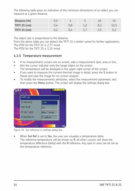
4.3.5 Temperature measurement
• If no measurement cursors are on screen, add a measurement spot, area or line. • Aim the cursor indicator onto the target object on the screen.
The temperature will be displayed in the upper right corner of the screen. • If you want to measure the current thermal image in detail, press the S button to
freeze and save the image for on-screen analysis• To modify the measurements attributes, select the measurement parameter, and
then press the Menu button. The screen will display the settings dialog box.
Figure 25 Set reference in settings dialog box
• When Set Ref is set to Yes, the user can visualize a temperature delta. The reference temperature will be shown as R, all other cursors will show the temperature difference (delta) with the R reference. Any spot or area can be set as the temperature reference.
25SKF TKTI 21 & 31
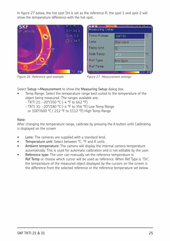
In igure 27 below, the hot spot SH is set as the reference R, the spot 1 and spot 2 will show the temperature difference with the hot spot.
Figure 26 Reference spot example Figure 27 Measurement settings
Select Setup->Measurement to show the Measuring Setup dialog box. • Temp Range: Select the temperature range best suited to the temperature of the
object being measured. The ranges available are: - TKTI 21: -20°/350 °C (-4 °F to 662 °F) - TKTI 31: -20°/180 °C (-4 °F to 356 °F) Low Temp Range
or 100°/600 °C ( 212 °F to 1112 °F) High Temp Range
Note: After changing the temperature range, calibrate by pressing the A button until Calibrating is displayed on the screen
• Lens: The cameras are supplied with a standard lend.• Temperature unit: Select between °C, °F and K units.• Ambient temperature: The camera will display the internal camera temperature
automatically. This is used for automatic calibration and is not editable by the user.• Reference type: The user can manually set the reference temperature in
Ref Temp or choose which cursor will be used as reference. When Ref Type is “On”, the temperature of the measured object displayed by the cursors on the screen is the difference from the selected reference or the reference temperature set below.

26 SKF TKTI 21 & 31
4.3.6 Alarms and Isotherms
Figure 28 Alarms and Isotherms
Select Setup->Alarms to show the Alarms dialog box.
A visible and/or audible alarm is triggered when an object is the scene will have a lower or higher temperature than the one set in the alarm setting. All pixels above or below this temperature will change to the colour as set in Alarm Colour. When the Alarm Colour is set to None, only the audible alarm will be heard. When using alarms with Area measurements, the selected measurement mode, Min, Max or Average will have to meet or exceed the set temperature in order to trigger the alarm.• Temp Alarm: Select Off to disable the alarm function and On to enable the alarm
function.• Alarm Type: Choose High for the Alarm to be triggered when the temperature goes
over the set limit. Choose Low for the Alarm to be triggered when the temperature goes below the set limit.
• Set Alarm Temp.: Sets the alarm detection temperature• Alarm Colour: Selects the colour in which the alarming pixels are displayed.
If set to None, no changes are made to the screen’s colour. • Isotherm Colour: Activates the Isotherm display by showing the part of the image in
the set temperature range in the chosen colour.• Isotherm Temp: Sets the centre temperature of the isotherm.• Isotherm Width: Sets the width of the displayed Isotherm band.
For example, if Isotherm Temp is set to 50 °C (122 °F) and Isotherm Width is set to 1 °C, the isotherm band will be from 49,5 °C (121.5 °F) to 50,5 °C (122.5 °F).
27SKF TKTI 21 & 31
4.4 Taking pictures
4.4.1 Freeze and Save images
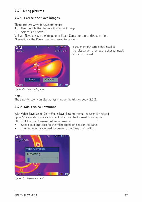
There are two ways to save an image:1. Use the S button to save the current image.2. Select File->SaveValidate Save to save the image or validate Cancel to cancel this operation. Alternatively, the C key may be pressed to cancel.
Figure 29 Save dialog box
If the memory card is not installed, the display will prompt the user to install a micro SD card.
Note: The save function can also be assigned to the trigger, see 4.2.3.2.
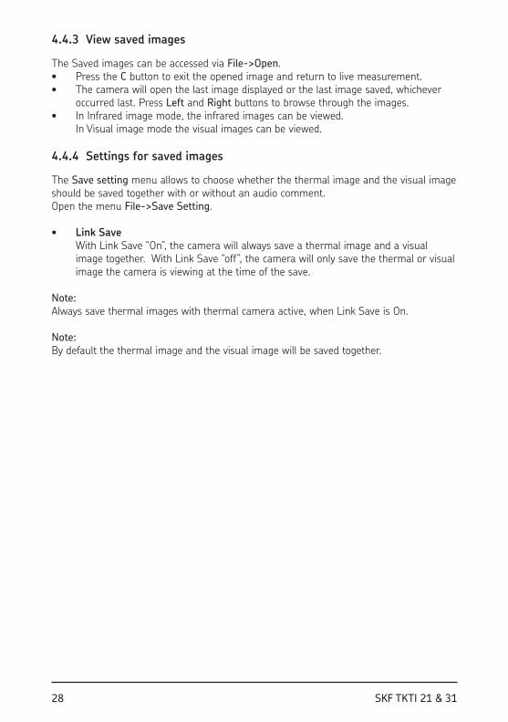
4.4.2 Add a voice Comment
With Voice Save set to On in File->Save Setting menu, the user can record up to 60 seconds of voice comment which can be listened to using the SKF TKTI Thermal Camera Software provided. • Speak loud and close to the microphone on the control panel. • The recording is stopped by pressing the Okay or C button.
Figure 30 Voice comment
28 SKF TKTI 21 & 31
4.4.3 View saved images
The Saved images can be accessed via File->Open.• Press the C button to exit the opened image and return to live measurement. • The camera will open the last image displayed or the last image saved, whichever
occurred last. Press Left and Right buttons to browse through the images. • In Infrared image mode, the infrared images can be viewed.
In Visual image mode the visual images can be viewed.
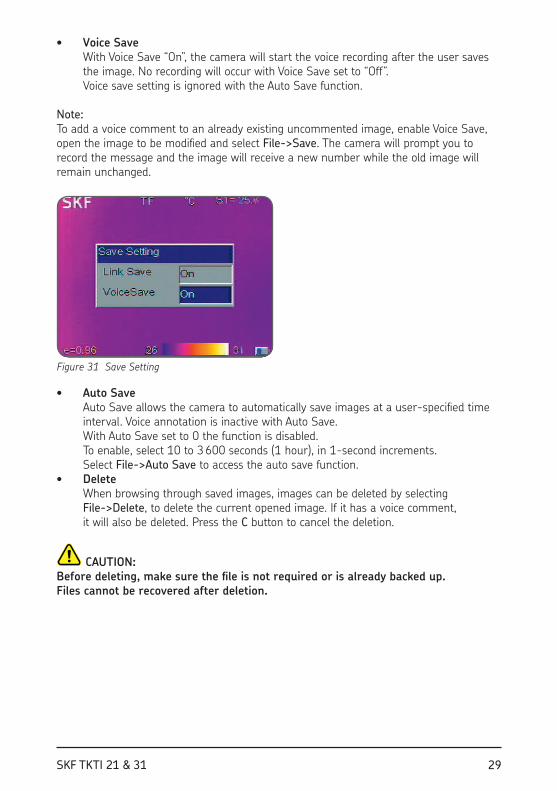
4.4.4 Settings for saved images
The Save setting menu allows to choose whether the thermal image and the visual image should be saved together with or without an audio comment.Open the menu File->Save Setting.
• Link Save With Link Save “On”, the camera will always save a thermal image and a visual
image together. With Link Save “off”, the camera will only save the thermal or visual image the camera is viewing at the time of the save.
Note: Always save thermal images with thermal camera active, when Link Save is On.
Note: By default the thermal image and the visual image will be saved together.
29SKF TKTI 21 & 31
• Voice Save With Voice Save “On”, the camera will start the voice recording after the user saves
the image. No recording will occur with Voice Save set to “Off”. Voice save setting is ignored with the Auto Save function.
Note: To add a voice comment to an already existing uncommented image, enable Voice Save, open the image to be modiied and select File->Save. The camera will prompt you to record the message and the image will receive a new number while the old image will remain unchanged.
Figure 31 Save Setting
• Auto Save Auto Save allows the camera to automatically save images at a user-speciied time
interval. Voice annotation is inactive with Auto Save. With Auto Save set to 0 the function is disabled. To enable, select 10 to 3 600 seconds (1 hour), in 1-second increments. Select File->Auto Save to access the auto save function.
• Delete When browsing through saved images, images can be deleted by selecting
File->Delete, to delete the current opened image. If it has a voice comment, it will also be deleted. Press the C button to cancel the deletion.
CAUTION: Before deleting, make sure the ile is not required or is already backed up. Files cannot be recovered after deletion.
30 SKF TKTI 21 & 31
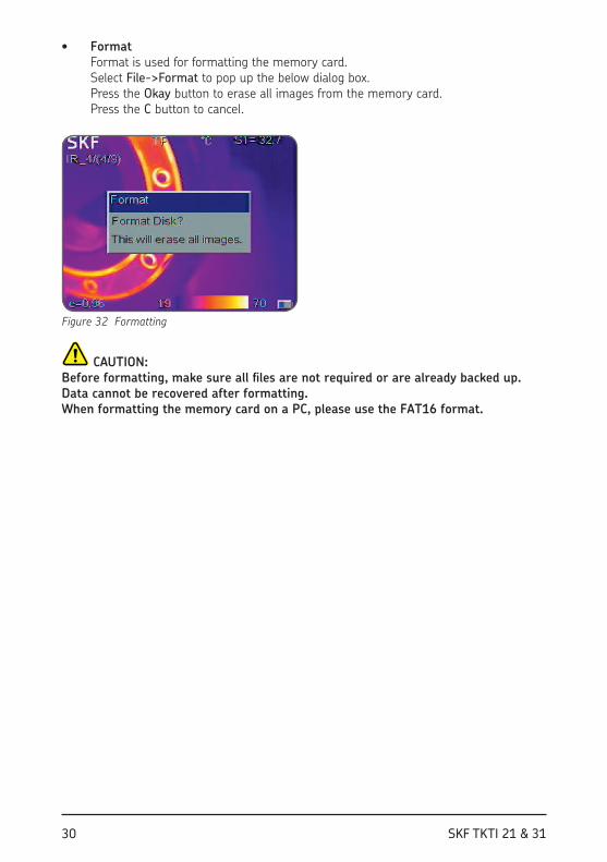
• Format Format is used for formatting the memory card.
Select File->Format to pop up the below dialog box. Press the Okay button to erase all images from the memory card. Press the C button to cancel.
Figure 32 Formatting
CAUTION: Before formatting, make sure all iles are not required or are already backed up. Data cannot be recovered after formatting. When formatting the memory card on a PC, please use the FAT16 format.
31SKF TKTI 21 & 31
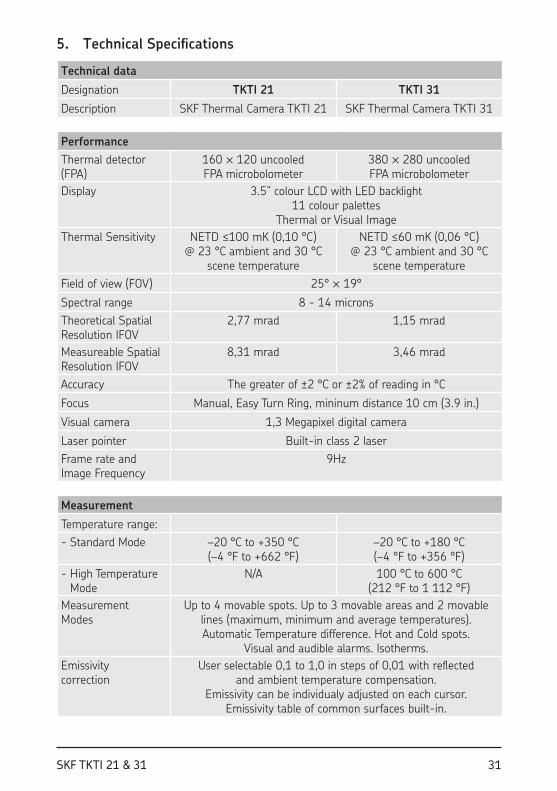
5. Technical Speciications
Technical data
Designation TKTI 21 TKTI 31
Description SKF Thermal Camera TKTI 21 SKF Thermal Camera TKTI 31
Performance
Thermal detector (FPA)
160 ™ 120 uncooled FPA microbolometer
380 ™ 280 uncooled FPA microbolometer
Display 3.5” colour LCD with LED backlight11 colour palettes
Thermal or Visual Image
Thermal Sensitivity NETD ≤100 mK (0,10 °C) @ 23 °C ambient and 30 °C
scene temperature
NETD ≤60 mK (0,06 °C) @ 23 °C ambient and 30 °C
scene temperature
Field of view (FOV) 25° ™ 19°
Spectral range 8 - 14 microns
Theoretical Spatial Resolution IFOV
2,77 mrad 1,15 mrad
Measureable Spatial Resolution IFOV
8,31 mrad 3,46 mrad
Accuracy The greater of ±2 °C or ±2% of reading in °C
Focus Manual, Easy Turn Ring, mininum distance 10 cm (3.9 in.)
Visual camera 1,3 Megapixel digital camera
Laser pointer Built-in class 2 laser
Frame rate and Image Frequency
9Hz
Measurement
Temperature range:
- Standard Mode –20 °C to +350 °C (–4 °F to +662 °F)
–20 °C to +180 °C (–4 °F to +356 °F)
- High Temperature Mode
N/A 100 °C to 600 °C (212 °F to 1 112 °F)
Measurement Modes
Up to 4 movable spots. Up to 3 movable areas and 2 movable lines (maximum, minimum and average temperatures). Automatic Temperature difference. Hot and Cold spots.
Visual and audible alarms. Isotherms.
Emissivity correction
User selectable 0,1 to 1,0 in steps of 0,01 with relected and ambient temperature compensation.
Emissivity can be individualy adjusted on each cursor. Emissivity table of common surfaces built-in.
32 SKF TKTI 21 & 31
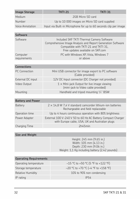
Image Storage TKTI 21 TKTI 31
Medium 2GB Micro SD card
Number Up to 10 000 images on Micro SD card supplied
Voice Annotation Input via Built-in Microphone for up to 60 seconds clip per image
Software
Software Included SKF TKTI Thermal Camera Software Comprehensive Image Analysis and Report Generation Software
Compatible with TKTI 21 and TKTI 31, Free updates available on SKF.com
Computer requirements
PC with Windows XP, Vista, Windows 7 or above
Connections
PC Connection Mini USB connector for image export to PC software (Cable provided)
External DC input 12V DC Input connector (DC Charger not provided)
Video Output 1 ™ Mini-jack Output for live image viewing (mini-jack to Video cable provided)
Mounting Handheld and tripod mounting 1/4” BSW
Battery and Power
Battery 2 ™ 14,8 W 7,4 V standard camcorder lithium-ion batteries Rechargeable and ield replaceable
Operation time Up to 4 hours continuous operation with 80% brightness
Power Adapter External 100 V-240 V 50 to 60 Hz AC Battery Compact Charger with Europe cable, USA, UK and Australian plugs
Charging Time 2h45min
Size and Weight
Height: 245 mm (9.65 in.) Width: 105 mm (4.13 in.) Depth: 230 mm (9.06 in.)
Weight: 1,1 Kg including battery (2.42 pounds)
Operating Requirements
Operating temperature –15 °C to +50 °C (5 °F to +122 °F)
Storage temperature –20 °C to +70 °C (–4 °F to +158 °F)
Relative Humidity 10% to 90% non condensing
IP rating IP54
33SKF TKTI 21 & 31
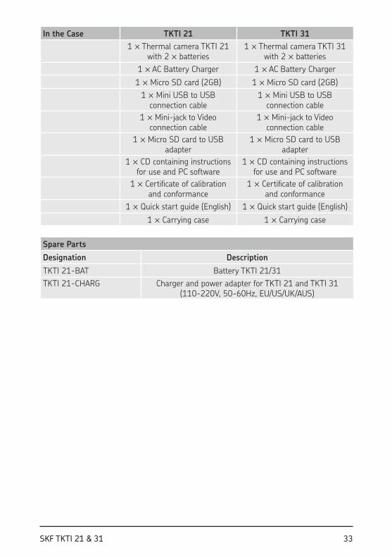
In the Case TKTI 21 TKTI 31
1 ™ Thermal camera TKTI 21 with 2 ™ batteries
1 ™ Thermal camera TKTI 31 with 2 ™ batteries
1 ™ AC Battery Charger 1 ™ AC Battery Charger
1 ™ Micro SD card (2GB) 1 ™ Micro SD card (2GB)
1 ™ Mini USB to USB connection cable
1 ™ Mini USB to USB connection cable
1 ™ Mini-jack to Video connection cable
1 ™ Mini-jack to Video connection cable
1 ™ Micro SD card to USB adapter
1 ™ Micro SD card to USB adapter
1 ™ CD containing instructions for use and PC software
1 ™ CD containing instructions for use and PC software
1 ™ Certiicate of calibration and conformance
1 ™ Certiicate of calibration and conformance
1 ™ Quick start guide (English) 1 ™ Quick start guide (English)
1 ™ Carrying case 1 ™ Carrying case
Spare Parts
Designation Description
TKTI 21-BAT Battery TKTI 21/31
TKTI 21-CHARG Charger and power adapter for TKTI 21 and TKTI 31 (110-220V, 50-60Hz, EU/US/UK/AUS)
34 SKF TKTI 21 & 31
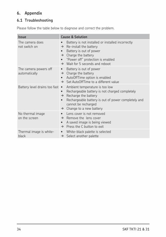
6. Appendix
6.1 Troubleshooting
Please follow the table below to diagnose and correct the problem.
Issue Cause & Solution
The camera does not switch on
• Battery is not installed or installed incorrectly d Re-install the battery• Battery is out of powerd Charge the battery• “Power off” protection is enabledd Wait for 5 seconds and reboot
The camera powers off automatically
• Battery is out of powerd Charge the battery• AutoOffTime option is enabledd Set AutoOffTime to a different value
Battery level drains too fast • Ambient temperature is too low• Rechargeable battery is not charged completelyd Recharge the battery• Rechargeable battery is out of power completely and
cannot be rechargedd Change to a new battery
No thermal image on the screen
• Lens cover is not removedd Remove the lens cover• A saved image is being viewedd Press the C button to exit
Thermal image is white-black
• White-black palette is selectedd Select another palette
35SKF TKTI 21 & 31
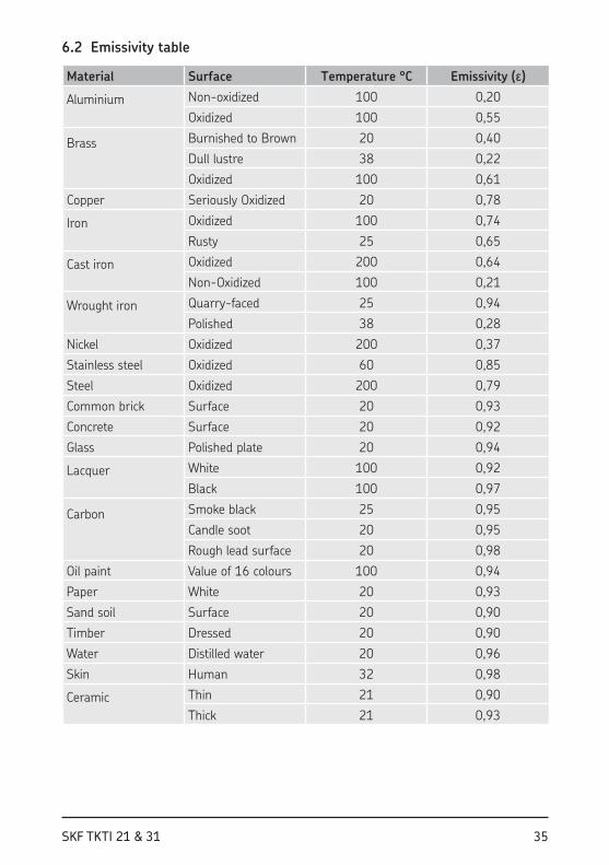
6.2 Emissivity table
Material Surface Temperature °C Emissivity (ε)
Aluminium Non-oxidized 100 0,20
Oxidized 100 0,55
Brass Burnished to Brown 20 0,40
Dull lustre 38 0,22
Oxidized 100 0,61
Copper Seriously Oxidized 20 0,78
Iron Oxidized 100 0,74
Rusty 25 0,65
Cast iron Oxidized 200 0,64
Non-Oxidized 100 0,21
Wrought iron Quarry-faced 25 0,94
Polished 38 0,28
Nickel Oxidized 200 0,37
Stainless steel Oxidized 60 0,85
Steel Oxidized 200 0,79
Common brick Surface 20 0,93
Concrete Surface 20 0,92
Glass Polished plate 20 0,94
Lacquer White 100 0,92
Black 100 0,97
Carbon Smoke black 25 0,95
Candle soot 20 0,95
Rough lead surface 20 0,98
Oil paint Value of 16 colours 100 0,94
Paper White 20 0,93
Sand soil Surface 20 0,90
Timber Dressed 20 0,90
Water Distilled water 20 0,96
Skin Human 32 0,98
Ceramic Thin 21 0,90
Thick 21 0,93

SKF Maintenance Products
www.mapro.skf.comwww.skf.com/mount
MP5417EN
® SKF is a registered trademark of the SKF Group. © SKF Group 2017/09
The contents of this publication are the copyright of the publisher and may not be reproduced (even extracts) unless prior written permission is granted. Every care has been taken to ensure the accuracy of the information contained in this publication but no liability can be accepted for any loss or damage whether direct, indirect or consequential arising out of the use of the information contained herein.
Recommended