SD
H
St
an
da
rd
P
ri
me
r
SDH Telecommunications Standard Primer
SDH Telecommunications StandardPrimer
What is SDH?
This document is intended as an introductory guide to the Synchronous Digital Hierarchy (SDH) multiplexing standard.
Standards in the telecommunications field are always evolving. Information in this SDH primer is based on the latest
information available from the ITU-T standardisation organization.
Use this primer as an introduction to the technology of SDH. Consult the actual material from ITU-T, paying particular
attention to the latest revision, if more detailed information is required.
For help in understanding the language of SDH telecommunications, a comprehensive Glossary appears at the end
of this document.
www.tektronix.com/optical i

www.tektronix.com/opticalii
Contents
What is SDH? . . . . . . . . . . . . . . . . . . . . . . . . . . . . . . . . . . . . . . . . . . . . . . . . . . . . . . . . . . . . . . . . . . . . . . . . i
Introduction To SDH . . . . . . . . . . . . . . . . . . . . . . . . . . . . . . . . . . . . . . . . . . . . . . . . . . . . . . . . . . . . . . . . . . . 1
Background . . . . . . . . . . . . . . . . . . . . . . . . . . . . . . . . . . . . . . . . . . . . . . . . . . . . . . . . . . . . . . . . . . . . . . . . . . . . . . . . . . . 1
Synchronisation of Digital Signals . . . . . . . . . . . . . . . . . . . . . . . . . . . . . . . . . . . . . . . . . . . . . . . . . . . . . . . . . . . . . . . . . . . . 1
SDH Advantages . . . . . . . . . . . . . . . . . . . . . . . . . . . . . . . . . . . . . . . . . . . . . . . . . . . . . . . . . . . . . . . . . . . . . . . . . . . . . . . . 2
Plesiochronous Digital Hierarchy (PDH) . . . . . . . . . . . . . . . . . . . . . . . . . . . . . . . . . . . . . . . . . . . . . . . . . . . . . . . . . . . . . . . . 2
Limitations of PDH Network . . . . . . . . . . . . . . . . . . . . . . . . . . . . . . . . . . . . . . . . . . . . . . . . . . . . . . . . . . . . . . . . . . . . . . . . 2
Basic SDH Signal . . . . . . . . . . . . . . . . . . . . . . . . . . . . . . . . . . . . . . . . . . . . . . . . . . . . . . . . . . . . . . . . . . . . . . . . . . . . . . . 3
Transmission Hierarchies . . . . . . . . . . . . . . . . . . . . . . . . . . . . . . . . . . . . . . . . . . . . . . . . . . . . . . . . . . . . . . . . . . . . . . . . . . 3
Introduction to Synchronisation . . . . . . . . . . . . . . . . . . . . . . . . . . . . . . . . . . . . . . . . . . . . . . . . . . . . . . . . . . . 4
Synchronous versus Asynchronous . . . . . . . . . . . . . . . . . . . . . . . . . . . . . . . . . . . . . . . . . . . . . . . . . . . . . . . . . . . . . . . . . . . 4
Synchronisation Hierarchy . . . . . . . . . . . . . . . . . . . . . . . . . . . . . . . . . . . . . . . . . . . . . . . . . . . . . . . . . . . . . . . . . . . . . . . . . 4
Synchronising SDH . . . . . . . . . . . . . . . . . . . . . . . . . . . . . . . . . . . . . . . . . . . . . . . . . . . . . . . . . . . . . . . . . . . . . . . . . . . . . . 4
Evolution of Timing and Synchronisation . . . . . . . . . . . . . . . . . . . . . . . . . . . . . . . . . . . . . . . . . . . . . . . . . . . . . . . . . . . . . . . . 4
SDH Frame Structure . . . . . . . . . . . . . . . . . . . . . . . . . . . . . . . . . . . . . . . . . . . . . . . . . . . . . . . . . . . . . . . . . . 5
Virtual Container . . . . . . . . . . . . . . . . . . . . . . . . . . . . . . . . . . . . . . . . . . . . . . . . . . . . . . . . . . . . . . . . . . . . . . . . . . . . . . . 5
SDH Overhead . . . . . . . . . . . . . . . . . . . . . . . . . . . . . . . . . . . . . . . . . . . . . . . . . . . . . . . . . . . . . . . . . . . . . . . 7
Regenerator Section Overhead . . . . . . . . . . . . . . . . . . . . . . . . . . . . . . . . . . . . . . . . . . . . . . . . . . . . . . . . . . . . . . . . . . . . . . 7
Multiplex Section Overhead . . . . . . . . . . . . . . . . . . . . . . . . . . . . . . . . . . . . . . . . . . . . . . . . . . . . . . . . . . . . . . . . . . . . . . . . 8
Higher-Order Path Overhead (VC-4/VC-3) . . . . . . . . . . . . . . . . . . . . . . . . . . . . . . . . . . . . . . . . . . . . . . . . . . . . . . . . . . . . . . . 10
Lower-Order Path Overhead (VC-2/VC-1) . . . . . . . . . . . . . . . . . . . . . . . . . . . . . . . . . . . . . . . . . . . . . . . . . . . . . . . . . . . . . . . 13
SDH Anomalies, Defects, Failures, and Alarms . . . . . . . . . . . . . . . . . . . . . . . . . . . . . . . . . . . . . . . . . . . . . . . . 15
Definitions . . . . . . . . . . . . . . . . . . . . . . . . . . . . . . . . . . . . . . . . . . . . . . . . . . . . . . . . . . . . . . . . . . . . . . . . . . . . . . . . . . . . 15
SDH Error Performance Monitoring . . . . . . . . . . . . . . . . . . . . . . . . . . . . . . . . . . . . . . . . . . . . . . . . . . . . . . . . . . . . . . . . . . . 15
SDH Pointers . . . . . . . . . . . . . . . . . . . . . . . . . . . . . . . . . . . . . . . . . . . . . . . . . . . . . . . . . . . . . . . . . . . . . . . . 17
Payload Pointers . . . . . . . . . . . . . . . . . . . . . . . . . . . . . . . . . . . . . . . . . . . . . . . . . . . . . . . . . . . . . . . . . . . . . . . . . . . . . . . 17
Positive Pointer Justification . . . . . . . . . . . . . . . . . . . . . . . . . . . . . . . . . . . . . . . . . . . . . . . . . . . . . . . . . . . . . . . . . . . . . . . . 17
Negative Pointer Justification . . . . . . . . . . . . . . . . . . . . . . . . . . . . . . . . . . . . . . . . . . . . . . . . . . . . . . . . . . . . . . . . . . . . . . . 18
SDH Multiplexing . . . . . . . . . . . . . . . . . . . . . . . . . . . . . . . . . . . . . . . . . . . . . . . . . . . . . . . . . . . . . . . . . . . . . 19
SDH Tributary Multiplexing . . . . . . . . . . . . . . . . . . . . . . . . . . . . . . . . . . . . . . . . . . . . . . . . . . . . . . . . . . . . . . 21
Tributary Unit Group . . . . . . . . . . . . . . . . . . . . . . . . . . . . . . . . . . . . . . . . . . . . . . . . . . . . . . . . . . . . . . . . . . . . . . . . . . . . . 21
TU Multiframe . . . . . . . . . . . . . . . . . . . . . . . . . . . . . . . . . . . . . . . . . . . . . . . . . . . . . . . . . . . . . . . . . . . . . . . . . . . . . . . . . 21
SDH Telecommunications Standard Primer

SDH Telecommunications StandardPrimer
TU Payload Pointer . . . . . . . . . . . . . . . . . . . . . . . . . . . . . . . . . . . . . . . . . . . . . . . . . . . . . . . . . . . . . . . . . . . . . . . . . . . . . . 22
Automatic Protection Switching . . . . . . . . . . . . . . . . . . . . . . . . . . . . . . . . . . . . . . . . . . . . . . . . . . . . . . . . . . 23
Multiplex Section Protection, K1/K2 Bytes . . . . . . . . . . . . . . . . . . . . . . . . . . . . . . . . . . . . . . . . . . . . . . . . . . . . . . . . . . . . . . 23
1+1 Protection . . . . . . . . . . . . . . . . . . . . . . . . . . . . . . . . . . . . . . . . . . . . . . . . . . . . . . . . . . . . . . . . . . . . . . . . . . . . . . . . 23
1:N Protection . . . . . . . . . . . . . . . . . . . . . . . . . . . . . . . . . . . . . . . . . . . . . . . . . . . . . . . . . . . . . . . . . . . . . . . . . . . . . . . . . 24
SDH Network Elements . . . . . . . . . . . . . . . . . . . . . . . . . . . . . . . . . . . . . . . . . . . . . . . . . . . . . . . . . . . . . . . . . 25
Terminal Multiplexer . . . . . . . . . . . . . . . . . . . . . . . . . . . . . . . . . . . . . . . . . . . . . . . . . . . . . . . . . . . . . . . . . . . . . . . . . . . . . 25
Regenerator . . . . . . . . . . . . . . . . . . . . . . . . . . . . . . . . . . . . . . . . . . . . . . . . . . . . . . . . . . . . . . . . . . . . . . . . . . . . . . . . . . . 25
Add/Drop Multiplexer . . . . . . . . . . . . . . . . . . . . . . . . . . . . . . . . . . . . . . . . . . . . . . . . . . . . . . . . . . . . . . . . . . . . . . . . . . . . 25
Wideband Digital Cross-connect . . . . . . . . . . . . . . . . . . . . . . . . . . . . . . . . . . . . . . . . . . . . . . . . . . . . . . . . . . . . . . . . . . . . . 26
Broadband Digital Cross-connect . . . . . . . . . . . . . . . . . . . . . . . . . . . . . . . . . . . . . . . . . . . . . . . . . . . . . . . . . . . . . . . . . . . . 26
Flexible Multiplexer . . . . . . . . . . . . . . . . . . . . . . . . . . . . . . . . . . . . . . . . . . . . . . . . . . . . . . . . . . . . . . . . . . . . . . . . . . . . . . 27
SDH Network Configurations . . . . . . . . . . . . . . . . . . . . . . . . . . . . . . . . . . . . . . . . . . . . . . . . . . . . . . . . . . . . . 27
Point-to-Point . . . . . . . . . . . . . . . . . . . . . . . . . . . . . . . . . . . . . . . . . . . . . . . . . . . . . . . . . . . . . . . . . . . . . . . . . . . . . . . . . 27
Point-to-Multipoint . . . . . . . . . . . . . . . . . . . . . . . . . . . . . . . . . . . . . . . . . . . . . . . . . . . . . . . . . . . . . . . . . . . . . . . . . . . . . . 27
Mesh Architecture . . . . . . . . . . . . . . . . . . . . . . . . . . . . . . . . . . . . . . . . . . . . . . . . . . . . . . . . . . . . . . . . . . . . . . . . . . . . . . 28
Ring Architecture . . . . . . . . . . . . . . . . . . . . . . . . . . . . . . . . . . . . . . . . . . . . . . . . . . . . . . . . . . . . . . . . . . . . . . . . . . . . . . . 28
Benefits of SDH – Conclusions . . . . . . . . . . . . . . . . . . . . . . . . . . . . . . . . . . . . . . . . . . . . . . . . . . . . . . . . . . . 29
Pointers, MUX/DEMUX . . . . . . . . . . . . . . . . . . . . . . . . . . . . . . . . . . . . . . . . . . . . . . . . . . . . . . . . . . . . . . . . . . . . . . . . . . . . 29
Reduced Back-to-Back Multiplexing . . . . . . . . . . . . . . . . . . . . . . . . . . . . . . . . . . . . . . . . . . . . . . . . . . . . . . . . . . . . . . . . . . 29
Optical Interconnect . . . . . . . . . . . . . . . . . . . . . . . . . . . . . . . . . . . . . . . . . . . . . . . . . . . . . . . . . . . . . . . . . . . . . . . . . . . . . 29
Multi-point Configurations . . . . . . . . . . . . . . . . . . . . . . . . . . . . . . . . . . . . . . . . . . . . . . . . . . . . . . . . . . . . . . . . . . . . . . . . . 29
Grooming . . . . . . . . . . . . . . . . . . . . . . . . . . . . . . . . . . . . . . . . . . . . . . . . . . . . . . . . . . . . . . . . . . . . . . . . . . . . . . . . . . . . 29
Enhanced OAM . . . . . . . . . . . . . . . . . . . . . . . . . . . . . . . . . . . . . . . . . . . . . . . . . . . . . . . . . . . . . . . . . . . . . . . . . . . . . . . . 29
Enhanced Performance Monitoring . . . . . . . . . . . . . . . . . . . . . . . . . . . . . . . . . . . . . . . . . . . . . . . . . . . . . . . . . . . . . . . . . . . 30
Convergence, ATM, Video, and SDH . . . . . . . . . . . . . . . . . . . . . . . . . . . . . . . . . . . . . . . . . . . . . . . . . . . . . . . . . . . . . . . . . . . 30
SONET Reference . . . . . . . . . . . . . . . . . . . . . . . . . . . . . . . . . . . . . . . . . . . . . . . . . . . . . . . . . . . . . . . . . . . . . 31
SONET and SDH Hierarchies . . . . . . . . . . . . . . . . . . . . . . . . . . . . . . . . . . . . . . . . . . . . . . . . . . . . . . . . . . . . . . . . . . . . . . . 31
Further Information . . . . . . . . . . . . . . . . . . . . . . . . . . . . . . . . . . . . . . . . . . . . . . . . . . . . . . . . . . . . . . . . . . . . . . . . . . . . . . 31
Glossary . . . . . . . . . . . . . . . . . . . . . . . . . . . . . . . . . . . . . . . . . . . . . . . . . . . . . . . . . . . . . . . . . . . . . . . . . . . 32
SDH Reference Materials . . . . . . . . . . . . . . . . . . . . . . . . . . . . . . . . . . . . . . . . . . . . . . . . . . . . . . . . . . . . . . . 37
ITU-T: . . . . . . . . . . . . . . . . . . . . . . . . . . . . . . . . . . . . . . . . . . . . . . . . . . . . . . . . . . . . . . . . . . . . . . . . . . . . . . . . . . . . . . . 37
www.tektronix.com/optical iii
www.tektronix.com/optical1
SDH Telecommunications Standard Primer
Introduction To SDH
SDH (Synchronous Digital Hierarchy) is a standard for telecommunica-
tions transport formulated by the International Telecommunication Union
(ITU), previously called the International Telegraph and Telephone
Consultative Committee (CCITT).
SDH was first introduced into the telecommunications network in 1992
and has been deployed at rapid rates since then. It’s deployed at all
levels of the network infrastructure, including the access network and
the long-distance trunk network. It’s based on overlaying a synchronous
multiplexed signal onto a light stream transmitted over fibre-optic cable.
SDH is also defined for use on radio relay links, satellite links, and at
electrical interfaces between equipment.
The comprehensive SDH standard is expected to provide the transport
infrastructure for worldwide telecommunications for at least the next two
or three decades.
The increased configuration flexibility and bandwidth availability of SDH
provides significant advantages over the older telecommunications sys-
tem. These advantages include:
A reduction in the amount of equipment and an increase in network reliability.
The provision of overhead and payload bytes – the overhead bytes permitting
management of the payload bytes on an individual basis and facilitating cen-
tralised fault sectionalisation.
The definition of a synchronous multiplexing format for carrying lower-level
digital signals (such as 2 Mbit/s, 34 Mbit/s, 140 Mbit/s) which greatly simpli-
fies the interface to digital switches, digital cross-connects, and add-drop
multiplexers.
The availability of a set of generic standards, which enable multi-vendor
interoperability.
The definition of a flexible architecture capable of accommodating future
applications, with a variety of transmission rates.
In brief, SDH defines synchronous transport modules (STMs) for the
fibre-optic based transmission hierarchy.
Background
Before SDH, the first generations of fibre-optic systems in the public
telephone network used proprietary architectures, equipment line codes,
multiplexing formats, and maintenance procedures. The users of this
equipment wanted standards so they could mix and match equipment
from different suppliers.
The task of creating such a standard was taken up in 1984 by the
Exchange Carriers Standards Association (ECSA) in the U.S. to establish
a standard for connecting one fibre system to another. In the late stages
of the development, the CCITT became involved so that a single interna-
tional standard might be developed for fibre interconnect between tele-
phone networks of different countries. The resulting international stan-
dard is known as Synchronous Digital Hierarchy (SDH).
Synchronisation of Digital Signals
To correctly understand the concepts and details of SDH, it’s important
to be clear about the meaning of Synchronous, Plesiochronous, and
Asynchronous.
In a set of Synchronous signals, the digital transitions in the signals
occur at exactly the same rate. There may however be a phase differ-
ence between the transitions of the two signals, and this would lie within
specified limits. These phase differences may be due to propagation
time delays, or low-frequency wander introduced in the transmission
network. In a synchronous network, all the clocks are traceable to one
Stratum 1 Primary Reference Clock (PRC). The accuracy of the PRC is
better than ±1 in 1011 and is derived from a cesium atomic standard.
If two digital signals are Plesiochronous, their transitions occur at
“almost” the same rate, with any variation being constrained within tight
limits. These limits are set down in ITU-T recommendation G.811. For
example, if two networks need to interwork, their clocks may be derived
from two different PRCs. Although these clocks are extremely accurate,
there’s a small frequency difference between one clock and the other.
This is known as a plesiochronous difference.
In the case of Asynchronous signals, the transitions of the signals don’t nec-
essarily occur at the same nominal rate. Asynchronous, in this case, means
that the difference between two clocks is much greater than a plesiochronous
difference. For example, if two clocks are derived from free-running quartz
oscillators, they could be described as asynchronous.
SDH Advantages
The primary reason for the creation of SDH was to provide a long-term
solution for an optical mid-span meet between operators; that is, to
allow equipment from different vendors to communicate with each other.
This ability is referred to as multi-vendor interworking and allows one
SDH-compatible network element to communicate with another, and to
replace several network elements, which may have previously existed
solely for interface purposes.
The second major advantage of SDH is the fact that it’s synchronous.
Currently, most fibre and multiplex systems are plesiochronous. This
means that the timing may vary from equipment to equipment because
they are synchronised from different network clocks. In order to multiplex
this type of signal, a process known as bit-stuffing is used. Bit-stuffing
adds extra bits to bring all input signals up to some common bit-rate,
thereby requiring multi-stage multiplexing and demultiplexing. Because
SDH is synchronous, it allows single-stage multiplexing and demultiplex-
ing. This single-stage multiplexing eliminates hardware complexity, thus
decreasing the cost of equipment while improving signal quality.
In plesiochronous networks, an entire signal had to be demultiplexed in
order to access a particular channel; then the non-accessed channels had
to be re-multiplexed back together in order to be sent further along the
network to their proper destination. In SDH format, only those channels
that are required at a particular point are demultiplexed, thereby eliminat-
ing the need for back-to-back multiplexing. In other words, SDH makes
individual channels “visible” and they can easily be added and dropped.
Plesiochronous Digital Hierarchy (PDH)
Traditionally, digital transmission systems and hierarchies have been based
on multiplexing signals which are plesiochronous (running at almost the same
speed). Also, various parts of the world use different hierarchies which lead to
problems of international interworking; for example, between those countries
using 1.544 Mbit/s systems (U.S.A. and Japan) and those using the
2.048 Mbit/s system.
To recover a 64 kbit/s channel from a 140 Mbit/s PDH signal, it’s neces-
sary to demultiplex the signal all the way down to the 2 Mbit/s level
before the location of the 64 kbit/s channel can be identified. PDH
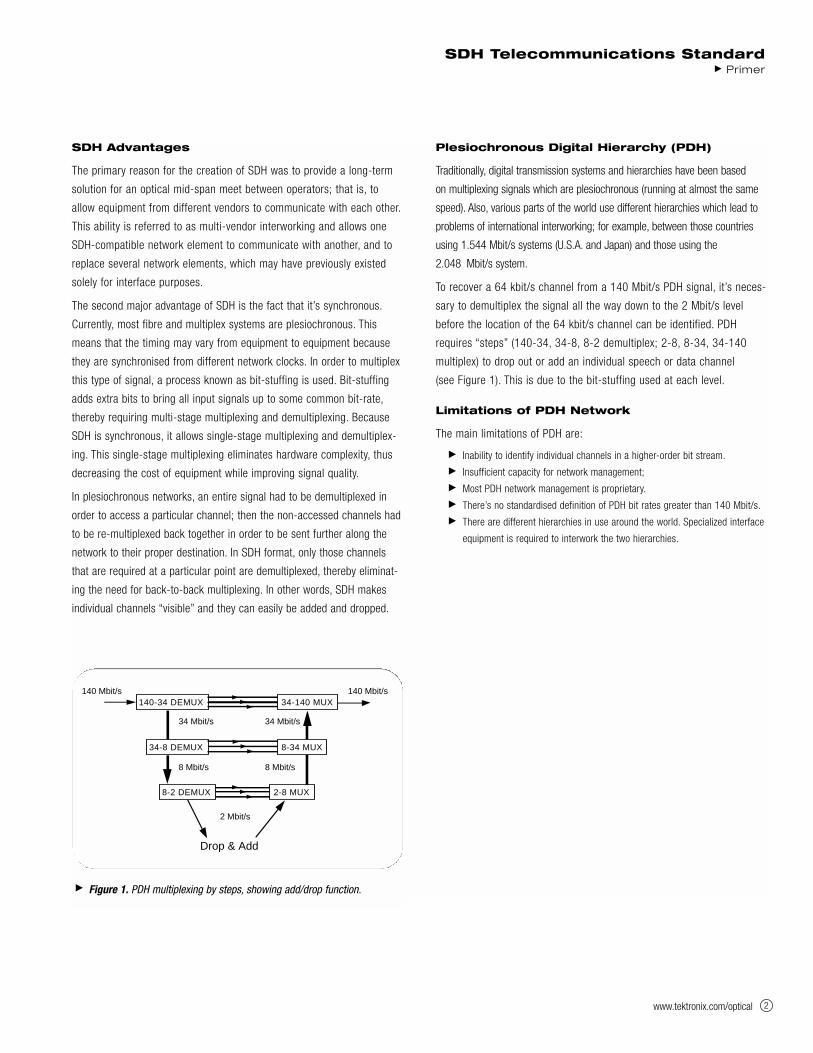
requires “steps” (140-34, 34-8, 8-2 demultiplex; 2-8, 8-34, 34-140
multiplex) to drop out or add an individual speech or data channel
(see Figure 1). This is due to the bit-stuffing used at each level.
Limitations of PDH Network
The main limitations of PDH are:
Inability to identify individual channels in a higher-order bit stream.
Insufficient capacity for network management;
Most PDH network management is proprietary.
There’s no standardised definition of PDH bit rates greater than 140 Mbit/s.
There are different hierarchies in use around the world. Specialized interface
equipment is required to interwork the two hierarchies.
SDH Telecommunications StandardPrimer
www.tektronix.com/optical 2
Figure 1. PDH multiplexing by steps, showing add/drop function.
140-34 DEMUX
34-8 DEMUX
34-140 MUX
8-34 MUX
2-8 MUX
140 Mbit/s 140 Mbit/s
8 Mbit/s
2 Mbit/s
34 Mbit/s
Drop & Add
8 Mbit/s
34 Mbit/s
8-2 DEMUX
www.tektronix.com/optical3
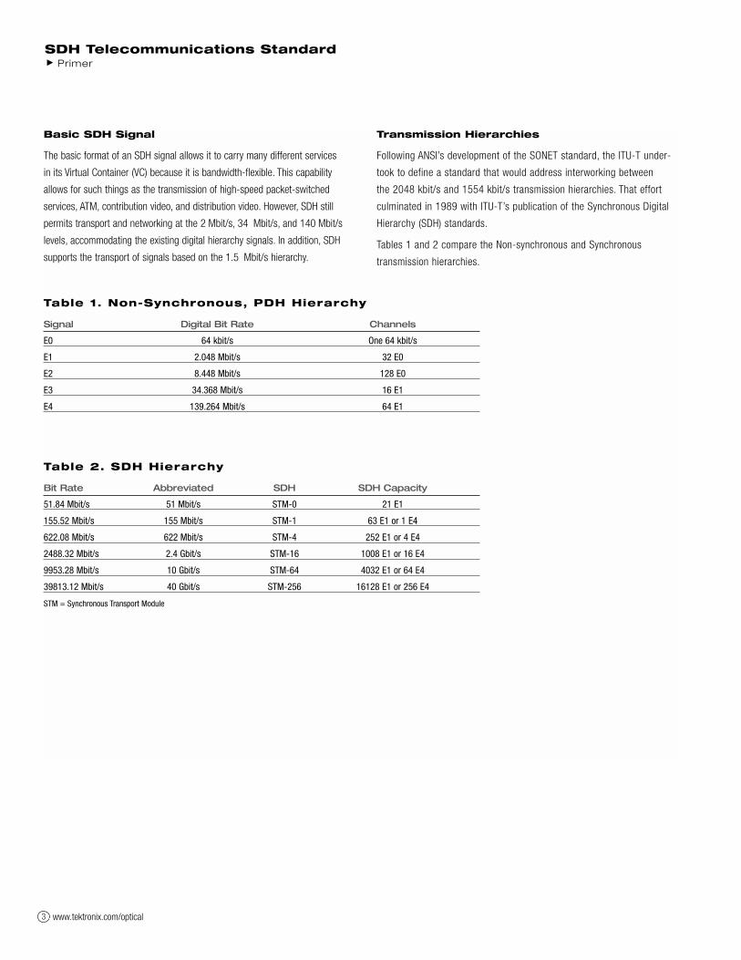
Basic SDH Signal
The basic format of an SDH signal allows it to carry many different services
in its Virtual Container (VC) because it is bandwidth-flexible. This capability
allows for such things as the transmission of high-speed packet-switched
services, ATM, contribution video, and distribution video. However, SDH still
permits transport and networking at the 2 Mbit/s, 34 Mbit/s, and 140 Mbit/s
levels, accommodating the existing digital hierarchy signals. In addition, SDH
supports the transport of signals based on the 1.5 Mbit/s hierarchy.
Transmission Hierarchies
Following ANSI’s development of the SONET standard, the ITU-T under-
took to define a standard that would address interworking between
the 2048 kbit/s and 1554 kbit/s transmission hierarchies. That effort
culminated in 1989 with ITU-T’s publication of the Synchronous Digital
Hierarchy (SDH) standards.
Tables 1 and 2 compare the Non-synchronous and Synchronous
transmission hierarchies.
SDH Telecommunications Standard Primer
Table 1. Non-Synchronous, PDH Hierarchy
Signal Digital Bit Rate Channels
E0 64 kbit/s One 64 kbit/s
E1 2.048 Mbit/s 32 E0
E2 8.448 Mbit/s 128 E0
E3 34.368 Mbit/s 16 E1
E4 139.264 Mbit/s 64 E1
Table 2. SDH Hierarchy
Bit Rate Abbreviated SDH SDH Capacity
51.84 Mbit/s 51 Mbit/s STM-0 21 E1
155.52 Mbit/s 155 Mbit/s STM-1 63 E1 or 1 E4
622.08 Mbit/s 622 Mbit/s STM-4 252 E1 or 4 E4
2488.32 Mbit/s 2.4 Gbit/s STM-16 1008 E1 or 16 E4
9953.28 Mbit/s 10 Gbit/s STM-64 4032 E1 or 64 E4
39813.12 Mbit/s 40 Gbit/s STM-256 16128 E1 or 256 E4
STM = Synchronous Transport Module

Introduction to Synchronisation
Synchronous versus Asynchronous
Traditionally, transmission systems have been asynchronous, with each
terminal in the network running on its own recovered clock timing. In
digital transmission, “timing” is one of the most fundamental operations.
Since these clocks are not synchronised, large variations can occur in the
clock rate and thus the signal bit rate. For example, an E3 signal specified
at 34 Mbit/s ±20 ppm (parts per million) can produce a timing difference
of up to 1789 bit/s between one incoming E3 signal and another.
Asynchronous multiplexing uses multiple stages. Signals such as asynchro-
nous E1s (2 Mbit/s) are multiplexed (bit-interleaving), extra bits are added
(bit-stuffing) to account for the timing variations of each individual stream
and are combined with other bits (framing bits) to form an E2 (8 Mbit/s)
stream. Bit-interleaving and bit-stuffing is used again to multiplex up to E3
(34 Mbit/s). The E1s are neither visible nor accessible within an E3 frame.
E3s are multiplexed up to higher rates in the same manner. At the higher
asynchronous rate, they cannot be accessed without demultiplexing.
In a synchronous system, such as SDH, the average frequency of all
clocks in the system is the same. Every slave clock can be traced back
to a highly stable reference clock. Thus, the STM-1 rate remains at a
nominal 155.52 Mbit/s, allowing many synchronous STM-1 signals to be
multiplexed without any bit-stuffing. Thus, the STM-1s are easily accessed
at a higher STM-N rate.
Low-speed synchronous virtual container (VC) signals are also simple to
interleave and transport at higher rates. At low speeds, 2.048 Mbit/s E1
signals are transported within synchronous VC-12 signals which run at
a constant rate of 2.304 Mbit/s. Single-step multiplexing up to STM-1
requires no bit-stuffing and VCs are easily accessed.
A mechanism known as “pointers,” operating in conjunction with buffers,
accommodates differences in the reference source frequencies and
phase wander, and so prevents data loss during synchronisation failures.
This is discussed in more detail later in this primer.
Synchronisation Hierarchy
Digital switches and digital cross-connect systems are commonly
employed in the digital network synchronisation hierarchy. The network
is organized with a master-slave relationship with clocks of the higher-
level nodes feeding timing signals to clocks of the lower-level nodes.
All nodes can be traced up to a Primary Reference Clock (PRC).
Synchronising SDH
The internal clock of an SDH terminal may derive its timing signal from
a Synchronisation Supply Unit (SSU) used by switching systems and
other equipment. Thus, this terminal can serve as a master for other
SDH nodes, providing timing on its outgoing STM-N signal. Other SDH
nodes will operate in a slave mode with their internal clocks timed by
the incoming STM-N signal. Present standards specify that an SDH
network must ultimately be able to derive its timing from a PRC.
Evolution of Timing and Synchronisation
This is a time of great change for Timing and Synchronisation in the
network and there are many challenges for operators and suppliers –
and many issues to resolve:
Synchronisation networks are changing with the introduction of SDH;
the historical PDH-based sync network will be replaced by an SDH-based
architecture.
New equipment, network timing, and sync standards have been developed
(Tektronix is contributing expertise at ITU and ETSI).
Transport networks are evolving and hybrid SDH/PDH has specific problems
due to the quantisation of network phase variation as pointer justifications.
New services such as video and ATM depend on excellent timing and
network sync to deliver good Quality of Service.
Jitter/Wander measurement technology is changing from analogue to digital,
leading to dramatically new instrument capabilities.
New test equipment standards are being developed (Tektronix is taking a
leading role at ITU).
These and many other timing and sync issues are addressed in another
publication from Tektronix: Performance Assessment of Timing and
Synchronisation in Broadband Networks. Copies can be requested
from Tektronix offices or by visiting www.tektronix.com.
SDH Telecommunications StandardPrimer
www.tektronix.com/optical 4
www.tektronix.com/optical5
SDH Frame Structure
The STM-1 frame is the basic transmission format for SDH. The frame
lasts for 125 microseconds, therefore, there are 8000 frames per second.
The STM-1 frame consists of overhead plus a virtual container capacity
(see Figure 2). The first nine columns of each frame make up the
Section Overhead, and the last 261 columns make up the Virtual
Container (VC) capacity. The VC plus the pointers (H1, H2, H3 bytes)
is called the AU (Administrative Unit).
Carried within the VC capacity, which has its own frame structure of nine rows
and 261 columns, is the Path Overhead and the Container (see Figure 3). The
first column is for Path Overhead; it’s followed by the payload container, which
can itself carry other containers.
Virtual Containers can have any phase alignment within the Administrative
Unit, and this alignment is indicated by the Pointer in row four, as described
later in the Pointers section. Within the Section Overhead, the first three
rows are used for the Regenerator Section Overhead, and the last five rows
are used for the Multiplex Section Overhead.
The STM frame is transmitted in a byte-serial fashion, row-by-row, and
is scrambled immediately prior to transmission to ensure adequate clock
timing content for downstream regenerators.
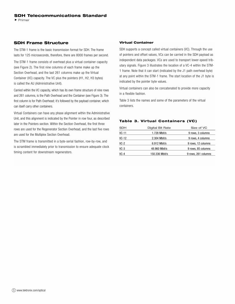
Virtual Container
SDH supports a concept called virtual containers (VC). Through the use
of pointers and offset values, VCs can be carried in the SDH payload as
independent data packages. VCs are used to transport lower-speed trib-
utary signals. Figure 3 illustrates the location of a VC-4 within the STM-
1 frame. Note that it can start (indicated by the J1 path overhead byte)
at any point within the STM-1 frame. The start location of the J1 byte is
indicated by the pointer byte values.
Virtual containers can also be concatenated to provide more capacity
in a flexible fashion.
Table 3 lists the names and some of the parameters of the virtual
containers.
SDH Telecommunications Standard Primer
Table 3. Virtual Containers (VC)
SDH Digital Bit Rate Size of VC
VC-11 1.728 Mbit/s 9 rows, 3 columns
VC-12 2.304 Mbit/s 9 rows, 4 columns
VC-2 6.912 Mbit/s 9 rows, 12 columns
VC-3 48.960 Mbit/s 9 rows, 85 columns
VC-4 150.336 Mbit/s 9 rows, 261 columns

www.tektronix.com/optical 6
SDH Telecommunications StandardPrimer
Figure 2. STM-1 frame structure.
9 Rows
Administrative Unit
Capacity of the Virtual Container
1
2
3
4
5
6
7
8
9
RegeneratorSectionOverhead
MultiplexSection
Overhead
H3H1 H2Pointers
STM-1 = 270 Columns (2430 bytes)
1 byte = One 64 kbit/s channel
H1H1H1 H2H2H2 H3H3H3
Frame = 125 µs Frame = 125 µsFrame = 125 µs
Overhead width = 9 columns
Figure 3. Virtual container structure showing VC-4.
9 Rows
STM-1 = 270 Columns
RegeneratorSection
Overhead
MultiplexSection
Overhead
1
2
3
4
5
6
7
8
9
Pointers
B2
D4
D7
K2
A1
B1
D1
H1
A1
B2
A1
B2
A2
E1
D2
H2
A2
H2
A2
H2
J 0 /Z0
F1
D3
H3 H3
D10
D5 D6
D8 D9
D11 D12
S1 M1 E2
Frame = 125 µsFrame = 125 µs Frame = 125 µs
Bounded by 261 columns
Wrap-around within SDH payload
B3
C2
G1
F2
H4
F3
K3
N1
J1K1
Path OverheadH3
www.tektronix.com/optical7
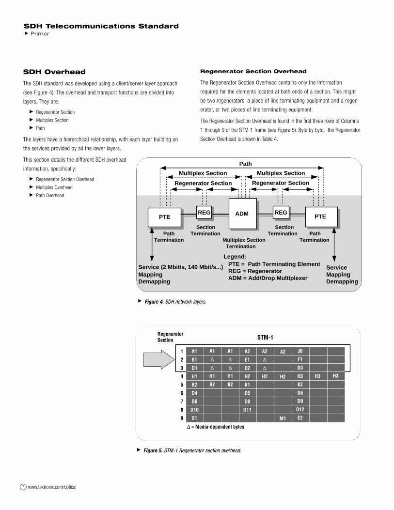
SDH Overhead
The SDH standard was developed using a client/server layer approach
(see Figure 4). The overhead and transport functions are divided into
layers. They are:
Regenerator Section
Multiplex Section
Path
The layers have a hierarchical relationship, with each layer building on
the services provided by all the lower layers.
This section details the different SDH overhead
information, specifically:
Regenerator Section Overhead
Multiplex Overhead
Path Overhead
Regenerator Section Overhead
The Regenerator Section Overhead contains only the information
required for the elements located at both ends of a section. This might
be two regenerators, a piece of line terminating equipment and a regen-
erator, or two pieces of line terminating equipment.
The Regenerator Section Overhead is found in the first three rows of Columns
1 through 9 of the STM-1 frame (see Figure 5). Byte by byte, the Regenerator
Section Overhead is shown in Table 4.
SDH Telecommunications Standard Primer
Figure 4. SDH network layers.
PathTermination
SectionTermination
Multiplex SectionTermination
PathTermination
SectionTermination
Service (2 Mbit/s, 140 Mbit/s...)MappingDemapping
PTE
Path
Multiplex Section
Regenerator Section Regenerator Section
Multiplex Section
REG
ServiceMappingDemapping
Legend:PTE = Path Terminating ElementREG = RegeneratorADM = Add/Drop Multiplexer
REGPTEADM
Figure 5. STM-1 Regenerator section overhead.
STM-1
1
2
3
4
5
6
7
8
9
A1
B1
D1
H1
B2
D4
D6
D10
S1
A1
∆
∆
H1
B2
A1
∆
∆
H1
B2
A2
E1
D2
H2
K1
D5
D8
D11
A2
∆
∆
H2
A2
H2
M1
J0
F1
D3
H3
K2
D6
D9
D12
E2
H3 H3
Regenerator Section
∆ = Media-dependent bytes
www.tektronix.com/optical 8
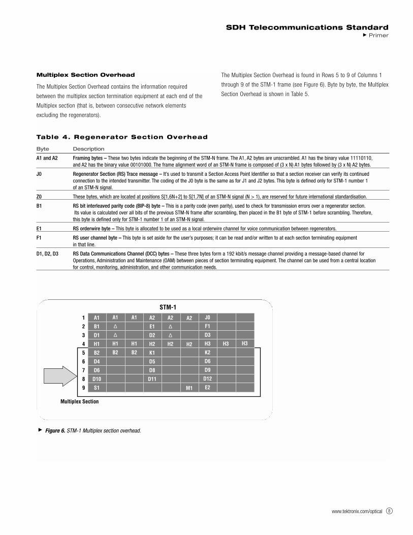
Multiplex Section Overhead
The Multiplex Section Overhead contains the information required
between the multiplex section termination equipment at each end of the
Multiplex section (that is, between consecutive network elements
excluding the regenerators).
The Multiplex Section Overhead is found in Rows 5 to 9 of Columns 1
through 9 of the STM-1 frame (see Figure 6). Byte by byte, the Multiplex
Section Overhead is shown in Table 5.
SDH Telecommunications StandardPrimer
Table 4. Regenerator Section Overhead
Byte Description
A1 and A2 Framing bytes – These two bytes indicate the beginning of the STM-N frame. The A1, A2 bytes are unscrambled. A1 has the binary value 11110110,and A2 has the binary value 00101000. The frame alignment word of an STM-N frame is composed of (3 x N) A1 bytes followed by (3 x N) A2 bytes.
J0 Regenerator Section (RS) Trace message – It’s used to transmit a Section Access Point Identifier so that a section receiver can verify its continued connection to the intended transmitter. The coding of the J0 byte is the same as for J1 and J2 bytes. This byte is defined only for STM-1 number 1 of an STM-N signal.
Z0 These bytes, which are located at positions S[1,6N+2] to S[1,7N] of an STM-N signal (N > 1), are reserved for future international standardisation.
B1 RS bit interleaved parity code (BIP-8) byte – This is a parity code (even parity), used to check for transmission errors over a regenerator section.Its value is calculated over all bits of the previous STM-N frame after scrambling, then placed in the B1 byte of STM-1 before scrambling. Therefore,
this byte is defined only for STM-1 number 1 of an STM-N signal.
E1 RS orderwire byte – This byte is allocated to be used as a local orderwire channel for voice communication between regenerators.
F1 RS user channel byte – This byte is set aside for the user’s purposes; it can be read and/or written to at each section terminating equipment in that line.
D1, D2, D3 RS Data Communications Channel (DCC) bytes – These three bytes form a 192 kbit/s message channel providing a message-based channel for Operations, Administration and Maintenance (OAM) between pieces of section terminating equipment. The channel can be used from a central location for control, monitoring, administration, and other communication needs.
Figure 6. STM-1 Multiplex section overhead.
STM-1
Multiplex Section
1
2
3
4
5
6
7
8
9
A1
B1
D1
H1
B2
D4
D6
D10
S1
A1
∆
∆
H1
B2
A1
H1
B2
A2
E1
D2
H2
K1
D5
D8
D11
A2
∆
∆
H2
A2
H2
M1
J0
F1
D3
H3
K2
D6
D9
D12
E2
H3 H3

www.tektronix.com/optical9
SDH Telecommunications Standard Primer
Table 5. Multiplex Section Overhead
Byte Description
B2 Multiplex Section (MS) bit interleaved parity code (MS BIP-24) byte – This bit interleaved parity N x 24 code is used to determine if a transmission error has occurred over a multiplex section. It’s even parity, and is calculated overall bits of the MS Overhead and the STM-N frame of the previous STM-N frame before scrambling. The value is placed in the three B2 bytes of the MS Overhead before scrambling. These bytes are provided for all STM-1 signals in an STM-N signal.
K1 and K2 Automatic Protection Switching (APS channel) bytes – These two bytes are used for MSP (Multiplex Section Protection) signaling between multiplex level entities for bi-directional automatic protection switching and for communicating Alarm Indication Signal (AIS) and Remote Defect Indication (RDI) conditions.The Multiplex Section Remote Defect Indication (MS-RDI) is used to return an indication to the transmit end that the received end has detected an incoming section defect or is receiving MS-AIS. MS-RDI is generated by inserting a “110” code in positions 6, 7, and 8 of the K2 byte before scrambling.
K1 Byte K2 Byte
Bits 1-4 Type of request Bits 1-4 Selects channel number
1111 Lock out of Protection Bit 5 Indication of architecture
1110 Forced Switch 0 1+1
1101 Signal Fail – High Priority 1 1:n
1100 Signal Fail – Low Priority Bits 6-8 Indicate mode of operation
1011 Signal Degrade – High Priority 111 MS-AIS
1010 Signal Degrade – Low Priority 110 MS-RDI
1001 (not used) 101 Provisioned mode is bi-directional
1000 Manual Switch 100 Provisioned mode is unidirectional
0111 (not used) 011 Future use
0110 Wait-to-Restore 010 Future use
0101 (not used) 001 Future use
0100 Exercise 000 Future use
0011 (not used)
0010 Reverse Request
0001 Do Not Revert
0000 No Request
Bits 5-8 Indicate the number of the channel requested
D4 to D12 MS Data Communications Channel (DCC) bytes – These nine bytes form a 576 kbit/s message channel from a central location for OAM information (control, maintenance, remote provisioning, monitoring, administration and other communication needs).
S1 Synchronisation status message byte (SSMB) – Bits 5 to 8 of this S1 byte are used to carry the synchronisation messages. Following is the assignment of bit patterns to the four synchronisation levels agreed to within ITU-T (other values are reserved):
Bits 5-8
0000 Quality unknown (existing sync. network)
0010 G.811 PRC
0100 SSU-A (G.812 transit)
1000 SSU-B (G.812 local)
1011 G.813 Option 1 Synchronous Equipment Timing Clock (SEC)
1111 Do not use for synchronisation. This message may be emulated by equipment failures and will be emulated by a Multiplex Section AIS signal.
M1 MS remote error indication – The M1 byte of an STM-1 or the first STM-1 of an STM-N is used for a MS layer remote error indication (MS-REI).Bits 2 to 8 of the M1 byte are used to carry the error count of the interleaved bit blocks that the MS BIP-24xN has detected to be in error at the far end of the section. This value is truncated at 255 for STM-N >4.
E2 MS orderwire byte – This orderwire byte provides a 64 kbit/s channel between multiplex entities for an express orderwire. It’s a voice channel for use by craftspersons and can be accessed at multiplex section terminations.

www.tektronix.com/optical 10
Higher-Order Path Overhead(VC-4/VC-3)
The Path Overhead is assigned to, and trans-
ported with the Virtual Container from the time
it’s created by path terminating equipment until
the payload is demultiplexed at the termination
point in a piece of path terminating equipment.
The Path Overhead is found in Rows 1 to 9
of the first column of the VC-4 or VC-3
(see Figure 7). Byte by byte, the Higher
Order Path Overhead is shown in Table 6.
SDH Telecommunications StandardPrimer
Table 6. Higher-Order Path Overhead
Byte Description
J1 Higher-Order VC-N path trace byte – This user-programmable byte repetitively transmits a 15-byte, E.64 format string plus 1-byte CRC-7.A 64-byte free-format string is also permitted for this Access Point Identifier. This allows the receiving terminal in a path to verify its continued connection to the intended transmitting terminal.
B3 Path bit interleaved parity code (Path BIP-8) byte – This is a parity code (even), used to determine if a transmission error has occurred over a path.Its value is calculated over all the bits of the previous virtual container before scrambling and placed in the B3 byte of the current frame.
C2 Path signal label byte – This byte specifies the mapping type in the VC-N. Standard binary values for C2 are:
MSB LSB Hex Code Interpretation
Bits 1-4 Bits 5-8
0000 0000 00 Unequipped or supervisory-unequipped
0000 0001 01 Equipped – non-specific
0000 0010 02 TUG structure
0000 0011 03 Locked TU-n
0000 0100 04 Asynchronous mapping of 34,368 kbit/s or 44,736 kbit/s into the Container-3
0001 0010 12 Asynchronous mapping of 139,264 kbit/s into the Container-4
0001 0011 13 ATM mapping
0001 0100 14 MAN DQDB (IEEE Standard 802.6) mapping
0001 0101 15 FDDI (ISO Standard 9314) mapping
0001 0110 16 Mapping of HDLC/PPP (Internet Standard 51) framed signal
0001 0111 17 Mapping of Simple Data Link (SDL) with SDH self synchronising scrambler
0001 1000 18 Mapping of HDLC/LAP-S framed signals
0001 1001 19 Mapping of Simple Data Link (SDL) with set-reset scrambler
0001 1010 1A Mapping of 10 Gbit/s Ethernet frames (IEEE 802.3)
1100 1111 CF Obsolete mapping of HDLC/PPP framed signal
1110 0001 E1 Reserved for national use
: : : :
1111 1100 FC Reserved for national use
1111 1110 FE Test signal, O.181 specific mapping
1111 1111 FF VC-AIS
Figure 7. Higher-order path overhead (VC-4/VC-3).
J1 J1 VC-n Path Trace
B3 B3 Path BIP-8
C2 C2 Path Signal Label
G1 G1 Path Status
F2 F2 Path User Channel
H4 H4 TU Multiframe Indicator
F3 F3 Path User Channel
K3 K3 Automatic Protection Switching
N1 N1 Network Operator (TCM)
1
2
3
4
5
6
7
8
9
Path OverheadSection Overhead
www.tektronix.com/optical11
SDH Telecommunications Standard Primer
Byte Description
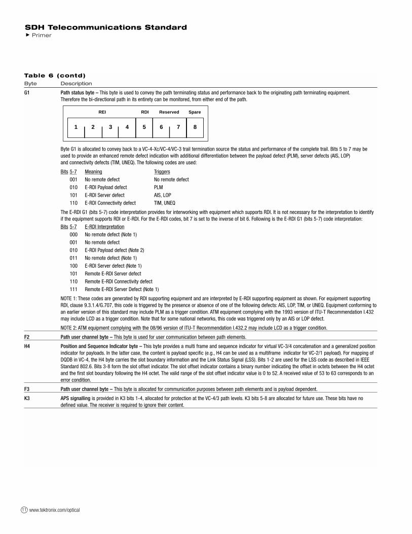
G1 Path status byte – This byte is used to convey the path terminating status and performance back to the originating path terminating equipment.Therefore the bi-directional path in its entirety can be monitored, from either end of the path.
Byte G1 is allocated to convey back to a VC-4-Xc/VC-4/VC-3 trail termination source the status and performance of the complete trail. Bits 5 to 7 may be used to provide an enhanced remote defect indication with additional differentiation between the payload defect (PLM), server defects (AIS, LOP) and connectivity defects (TIM, UNEQ). The following codes are used:
Bits 5-7 Meaning Triggers
001 No remote defect No remote defect
010 E-RDI Payload defect PLM
101 E-RDI Server defect AIS, LOP
110 E-RDI Connectivity defect TIM, UNEQ
The E-RDI G1 (bits 5-7) code interpretation provides for interworking with equipment which supports RDI. It is not necessary for the interpretation to identify if the equipment supports RDI or E-RDI. For the E-RDI codes, bit 7 is set to the inverse of bit 6. Following is the E-RDI G1 (bits 5-7) code interpretation:
Bits 5-7 E-RDI Interpretation
000 No remote defect (Note 1)
001 No remote defect
010 E-RDI Payload defect (Note 2)
011 No remote defect (Note 1)
100 E-RDI Server defect (Note 1)
101 Remote E-RDI Server defect
110 Remote E-RDI Connectivity defect
111 Remote E-RDI Server Defect (Note 1)
NOTE 1: These codes are generated by RDI supporting equipment and are interpreted by E-RDI supporting equipment as shown. For equipment supporting RDI, clause 9.3.1.4/G.707, this code is triggered by the presence or absence of one of the following defects: AIS, LOP, TIM, or UNEQ. Equipment conforming toan earlier version of this standard may include PLM as a trigger condition. ATM equipment complying with the 1993 version of ITU-T Recommendation I.432 may include LCD as a trigger condition. Note that for some national networks, this code was triggered only by an AIS or LOP defect.
NOTE 2: ATM equipment complying with the 08/96 version of ITU-T Recommendation I.432.2 may include LCD as a trigger condition.
F2 Path user channel byte – This byte is used for user communication between path elements.
H4 Position and Sequence Indicator byte – This byte provides a multi frame and sequence indicator for virtual VC-3/4 concatenation and a generalized position indicator for payloads. In the latter case, the content is payload specific (e.g., H4 can be used as a multiframe indicator for VC-2/1 payload). For mapping of DQDB in VC-4, the H4 byte carries the slot boundary information and the Link Status Signal (LSS). Bits 1-2 are used for the LSS code as described in IEEE Standard 802.6. Bits 3-8 form the slot offset indicator. The slot offset indicator contains a binary number indicating the offset in octets between the H4 octet and the first slot boundary following the H4 octet. The valid range of the slot offset indicator value is 0 to 52. A received value of 53 to 63 corresponds to an error condition.
F3 Path user channel byte – This byte is allocated for communication purposes between path elements and is payload dependent.
K3 APS signalling is provided in K3 bits 1-4, allocated for protection at the VC-4/3 path levels. K3 bits 5-8 are allocated for future use. These bits have no defined value. The receiver is required to ignore their content.
1 2 3 4 5 6 7 8
REI RDI Reserved Spare
Table 6 (contd)

www.tektronix.com/optical 12
SDH Telecommunications StandardPrimer
Byte Description
N1 Network operator byte – This byte is allocated to provide a Higher-Order Tandem Connection Monitoring (HO-TCM) function. N1 is allocated for Tandem Connection Monitoring for contiguous concatenated VC-4, the VC-4 and VC-3 levels.
Bits 1-4 Incoming Error Count (IEC).
1001 0
0001 1
0010 2
0011 3
0100 4
0101 5
0110 6
0111 7
1000 8
1110 Incoming AIS
NOTE: To guarantee a non all-zeroes N1 byte independent of the incoming signal status, it is required that the IEC code field contains at least one “1”.When zero errors in the BIP-8 of the incoming signal are detected, an IEC code is inserted with “1”s in it. In this manner, it is possible for the Tandem Connection sink at the tail end of the Tandem Connection link to use the IEC code field to distinguish between unequipped conditions started within or before the Tandem Connection.
Bit 5 Operates as the TC-REI of the Tandem Connection to indicate errored blocks caused within the Tandem Connection.
Bit 6 Operates as the OEI to indicate errored blocks of the egressing VC-n.
Bits 7-8 Operate in a 76 multiframe as:
– Access point identifier of the Tandem Connection (TC-APId); it complies with the generic 16-byte string format given in 9.2.2.2.
– TC-RDI, indicating to the far end that defects have been detected within the Tandem Connection at the near end Tandem Connection sink.
– ODI, indicating to the far end that AU/TU-AIS has been inserted into the egressing AU-n/TU-n at the TC-sink due to defects before or within the Tandem Connection.
– Reserved capacity (for future standardization).
Frame # Bits 7-8 definition
1-8 Frame Alignment Signal: 1111 1111 1111 1110
9-12 TC-APId byte #1 [ 1 C1C2C3C4C5C6C7 ]
13-16 TC-APId byte #2 [ 0 X X X X X X X ]
17-20 TC-APId byte #3 [ 0 X X X X X X X ]
: :
65-68 TC-APId byte #15 [ 0 X X X X X X X ]
69-72 TC-APId byte #16 [ 0 X X X X X X X ]
73-76 TC-RDI, ODI and Reserved (see following)
Frame # Bit 7 definition Bit 8 definition
73 Reserved (default = “0”) TC-RDI
74 ODI Reserved (default = “0”)
75 Reserved (default = “0”) Reserved (default = “0”)
76 Reserved (default = “0”) Reserved (default = “0”)
1 2 3 4 5 6 7 8
IEC TC-REI OEITC-APId, TC-RDI,ODI, reserved
Table 6 (contd)

www.tektronix.com/optical13
Lower-Order Path Overhead (VC-2/VC-1)
The bytes V5, J2, N2, and K4 are allocated to the VC-2/VC-1 POH. The
V5 byte is the first byte of the multiframe and its position is indicated
by the TU-2/TU-1 pointer. The V5 byte provides the functions of error
checking, signal label, and path status of the VC-2/VC-1 paths. The bit
assignments for the V5 byte and the byte-by-byte Lower Order Path
Overhead is shown in Table 7.
SDH Telecommunications Standard Primer
Table 7. Lower-Order Path Overhead
Byte Description
V5 VT path overhead byte.
Bits 1-2 Allocated for error performance monitoring. A Bit Interleaved Parity (BIP-2) scheme is specified. Includes POH bytes,but excludes V1, V2, V3, and V4.
Bit 3 A VC-2/VC-1 path Remote Error Indication (LP-REI) that is set to one and sent back towards a VC-2/VC-1 path originator if one or more errors were detected by the BIP-2; otherwise set to zero.
Bit 4 A VC-2/VC-1 path Remote Failure Indication (LP-RFI). This bit is set to one if a failure is declared, otherwise it is set to zero.A failure is a defect that persists beyond the maximum time allocated to the transmission system protection mechanisms.
Bits 5-7 Provide a VC-2/VC-1 signal label. The Virtual Container path Signal Label coding is:
000 Unequipped or supervisory-unequipped
001 Equipped – non-specific
010 Asynchronous
011 Bit synchronous
100 Byte synchronous
101 Reserved for future use
110 Test signal, O.181 specific mapping
111 VC-AIS
Bit 8 Set to 1 to indicate a VC-2/VC-1 path Remote Defect Indication (LP-RDI); otherwise set to zero.
J2 Used to repetitively transmit a Lower-Order Access Path Identifier so that a path receiving terminal can verify its continued connection to the intended transmitter. A 16-byte frame is defined for the transmission of Path Access Point Identifiers. This 16-byte frame is identical to the 16-byte frame of the J1 and J0 bytes.
1 2 3 4 5 6 7 8
BIP-2 REI RFI Signal Label RDI
www.tektronix.com/optical 14
SDH Telecommunications StandardPrimer
Table 7 (contd)
Byte Description
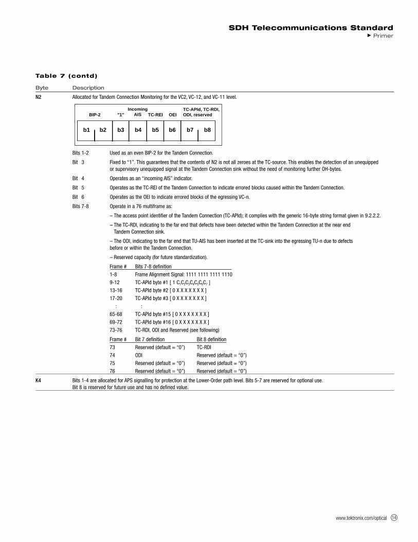
N2 Allocated for Tandem Connection Monitoring for the VC2, VC-12, and VC-11 level.
Bits 1-2 Used as an even BIP-2 for the Tandem Connection.
Bit 3 Fixed to “1”. This guarantees that the contents of N2 is not all zeroes at the TC-source. This enables the detection of an unequipped or supervisory unequipped signal at the Tandem Connection sink without the need of monitoring further OH-bytes.
Bit 4 Operates as an “incoming AIS” indicator.
Bit 5 Operates as the TC-REI of the Tandem Connection to indicate errored blocks caused within the Tandem Connection.
Bit 6 Operates as the OEI to indicate errored blocks of the egressing VC-n.
Bits 7-8 Operate in a 76 multiframe as:
– The access point identifier of the Tandem Connection (TC-APId); it complies with the generic 16-byte string format given in 9.2.2.2.
– The TC-RDI, indicating to the far end that defects have been detected within the Tandem Connection at the near endTandem Connection sink.
– The ODI, indicating to the far end that TU-AIS has been inserted at the TC-sink into the egressing TU-n due to defects before or within the Tandem Connection.
– Reserved capacity (for future standardization).
Frame # Bits 7-8 definition
1-8 Frame Alignment Signal: 1111 1111 1111 1110
9-12 TC-APId byte #1 [ 1 C1C2C3C4C5C6C7 ]
13-16 TC-APId byte #2 [ 0 X X X X X X X ]
17-20 TC-APId byte #3 [ 0 X X X X X X X ]
: :
65-68 TC-APId byte #15 [ 0 X X X X X X X ]
69-72 TC-APId byte #16 [ 0 X X X X X X X ]
73-76 TC-RDI, ODI and Reserved (see following)
Frame # Bit 7 definition Bit 8 definition
73 Reserved (default = “0”) TC-RDI
74 ODI Reserved (default = “0”)
75 Reserved (default = “0”) Reserved (default = “0”)
76 Reserved (default = “0”) Reserved (default = “0”)
K4 Bits 1-4 are allocated for APS signalling for protection at the Lower-Order path level. Bits 5-7 are reserved for optional use.Bit 8 is reserved for future use and has no defined value.
b1 b2 b3 b4 b5 b6 b7 b8
BIP-2 "1" TC-REI OEITC-APId, TC-RDI,ODI, reserved
IncomingAIS

www.tektronix.com/optical15
SDH Anomalies, Defects, Failures, and Alarms
The SDH frame structure has been designed to contain a large amount
of overhead information. The overhead information provides for a variety
of management and other functions such as:
Alarm Indication Signals (AIS)
Error Performance Monitoring using BIP-N
Pointer Adjustment Information
Path Status
Path Trace
Section Trace
Remote Defect, Error, and Failure Indications
Signal Labels
New Data Flag Indications
Data Communications Channels (DCC)
Automatic Protection Switching (APS) Control
Orderwire
Synchronisation Status Message
Much of this overhead information is involved with alarm and in-service
monitoring of the particular SDH sections. Table 8 and Figure 9, that fol-
low the definitions, list the criteria for errors and the performance moni-
toring for errors.
Definitions
Alarm – The maintenance signal used in the digital network to alert down-
stream equipment that a defect or equipment failure has been detected.
Anomaly – The smallest discrepancy which can be observed between
the actual and desired characteristics of an item. The occurrence of a
single anomaly does not constitute an interruption in the ability to per-
form a required function. Examples of SDH anomalies are:
B1 BIP
B2 BIP
Path B3 BIP
REI
Pattern Bit (OOS test)
Defect – The density of anomalies has reached a level where the ability
to perform a required function has been interrupted. Defects are used as
input for performance monitoring, the control of consequent actions, and
the determination of fault cause. Examples of SDH Defects are:
OOF
AIS
RDI
LOF
LOP
LOM
Failure – The inability of a function to perform a required action which
has persisted beyond a maximum time allocated.
SDH Error Performance Monitoring
Error performance monitoring in the SDH is based on Bit-Interleaved-
Parity (BIP) checks calculated on a frame-by-frame basis. These BIP
checks are inserted in the Regenerator
Section Overhead, Multiplex Section
Overhead, and Path Overheads.
In addition, Higher-Order Path
Terminating Equipment (HO PTE) and
Lower-Order Path Terminating
Equipment (LO PTE) produce Remote
Error Indications (REI) based on errors
detected in the HO Path and LO Path
BIP respectively. The REI signals are
sent back to the equipment at the origi-
nating end of a path. All defects listed
in Figure 8 are described in Table 8.
SDH Telecommunications Standard Primer
Figure 8. Interaction between defects in forward and backward directions, according to the different SDH levels.
MSTE RSTEHO PTELO PTE RSTE RSTE MSTE HO PTE LO PTE
Regenerator Section (RSOH)
Multiplex Section (MSOH)
Higher Order Path
Lower Order Path
Alarm Transmission
Alarm Detection
RDI(V5)
RDI(G1)
RDI(K2)
RDI(K2)
RDI(G1)
RDI(V5)
MSA I S
LOPLOSLOF
AU-AIS
LOP
TU-AIS(V1,V2)
MSA I S
LOSLOF
LOSLOF Tributary
A I S
(H1,H2)

www.tektronix.com/optical 16
SDH Telecommunications StandardPrimer
Table 8. Anomalies, Defects, Failures, Alarms
Abbreviation Description Criteria
LOS Loss of Signal LOS is raised when the synchronous signal (STM-N) level drops below the threshold at which a BER of 1 in 103 is predicted. It could be due to a cut cable, excessive attenuation of the signal, or equipment fault.The LOS state will clear when two consecutive framing patterns are received and no new LOS condition is detected.
OOF Out of Frame Alignment OOF state occurs when several consecutive SDH frames are received with invalid (errored) framing patterns (A1 and A2 bytes). The maximum time to detect OOF is 625 microseconds. OOF state clears within 250 microseconds when two consecutive SDH frames are received with valid framing patterns.
LOF Loss of Frame LOF state occurs when the OOF state exists for a specified time in microseconds. The LOF state clears when Alignment an in-frame condition exists continuously for a specified time in microseconds. The time for detection and clearance
is normally 3 milliseconds.
LOP Loss of Pointer LOP state occurs when N consecutive invalid pointers are received or N consecutive New Data Flags (NDF) are received (other than in a concatenation indicator), where N = 8, 9, or 10. LOP state is cleared when three equal valid pointers or three consecutive AIS indications are received.LOP can be identified as:• AU-LOP (Administrative Unit Loss of Pointer)• TU-LOP (Tributary Unit Loss of Pointer)
AIS Alarm Indication AIS is an all-ONES characteristic or adapted information signal. It’s generated to replace the normal traffic signal when it Signal contains a defect condition in order to prevent consequential downstream failures being declared or alarms being raised.
AIS can be identified as:• MS-AIS (Multiplex Section Alarm Indication Signal)• AU-AIS (Administrative Unit Alarm Indication Signal)• TU-AIS (Tributary Unit Alarm Indication Signal)
REI Remote Error An indication returned to a transmitting node (source) that an errored block has been detected at the receiving node (sink).Indication This indication was previously known as FEBE (Far End Block Error).
REI can be identified as:• MS-REI (Multiplex Section Remote Error Indication)• HP-REI (Higher-order Path Remote Error Indication)• LP-REI (Lower-order Path Remote Error Indication)
RDI Remote Defect A signal returned to the transmitting Terminating Equipment upon detecting a Loss of Signal, Loss of Frame, or AIS defect.Indication RDI was previously known as FERF (Far End Receiver Failure).
RDI can be identified as:• MS-RDI (Multiplex Section Remote Defect Indication)• HP-RDI (Higher-order Path Remote Defect Indication)• LP-RDI (Lower-order Path Remote Defect Indication)
RFI Remote Failure A failure is a defect that persists beyond the maximum time allocated to the transmission system protection mechanisms.Indication When this situation occurs, an RFI is sent to the far end and will initiate a path protection switch if this function has
been provisioned.RFI can be identified as:• LP-RFI (Lower-order Path Remote Failure Indication)
B1 error B1 error Parity errors evaluated by byte B1 (BIP-8) of an STM-N shall be monitored. If any of the eight parity checks fail,the corresponding block is assumed to be in error.
B2 error B2 error Parity errors evaluated by byte B2 (BIP-24 x N) of an STM-N shall be monitored. If any of the N x 24 parity checks fail,the corresponding block is assumed to be in error.
B3 error B3 error Parity errors evaluated by byte B3 (BIP-8) of a VC-N (N = 3,4) shall be monitored. If any of the eight parity checks fail,the corresponding block is assumed to be in error.
BIP-2 error BIP-2 error Parity errors contained in bits 1 and 2 (BIP-2) of byte V5 of a VC-m (m=11,12,2) shall be monitored. If any of the two parity checks fail, the corresponding block is assumed to be in error.
LSS Loss of Sequence Out-of-service bit error measurements using pseudo-random sequences can only be performed if the reference sequence Synchronisation produced on the receiving side of the test set-up is correctly synchronised to the sequence coming from the object
under test. In order to achieve compatible measurement results, it’s necessary that the sequence synchronisation characteristics are specified. The following requirement is applicable to all ITU-T O.150 Recommendations dealing with error performance measurements using pseudo-random sequences.Sequence synchronisation shall be considered to be lost and re-synchronisation shall be started if:• The bit error ratio is ≥ 0.20 during an integration interval of 1 second; or• It can be unambiguously identified that the test sequence and the reference sequence are out of phase.

www.tektronix.com/optical17
SDH Pointers
SDH provides payload pointers to permit differences in the phase and
frequency of the Virtual Containers (VC-N) with respect to the STM-N
frame. Lower-order pointers are also provided to permit phase differ-
ences between VC-1/VC-2 and the higher-order VC-3/VC-4.
On a frame-by-frame basis, the payload pointer indicates the offset
between the VC payload and the STM-N frame by identifying the location
of the first byte of the VC in the payload. In other words, the VC is
allowed to “float” within the STM-1 frame capacity.
To make this possible, within each STM-N frame, there’s a pointer,
known as the VC Payload Pointer, that indicates where the actual pay-
load container starts. For a VC-4 payload, this pointer is located in
columns 1 and 4 of the fourth row of the Section Overhead. The bytes
H1 and H2 (two 8-bit bytes) of the Overhead can be viewed as one value
(see Figure 9).
The pointer value indicates the offset in bytes from the pointer to the
first byte of the VC, which is the J1 byte. Because the Section Overhead
bytes are not counted, and starting points are at 3-byte increments for a
VC-4 payload, the possible range is:
Total STM-1 bytes – Section Overhead bytes = Pointer value range
For example:
(2430 – 81)/3 = 783 valid pointer positions
That is, the value of the pointer has a range of 0 to 782. For example, if
the VC-4 Payload Pointer has a value of 0, then the VC-4 begins in the
byte adjacent to the H3 byte of the Overhead; if the Payload Pointer has
a value of 87, then the VC-4 begins in the byte adjacent to the K2 byte
of the Overhead in the next row.
The pointer value, which is a binary number, is carried in bits 7 through
16 of the H1-H2 pointer word. The first four bits of the VC-4 payload
pointer make provision for indicating a change in the VC, and thus an
arbitrary change in the value of the pointer. These four bits, the N-bits,
are known as the New Data Flag. The VC pointer value that accompanies
the New Data Flag will indicate the new offset.
Payload Pointers
When there’s a difference in phase or frequency, the pointer value is
adjusted. To accomplish this, a process known as byte stuffing is used.
In other words, the VC payload pointer indicates where in the container
capacity a VC starts, and the byte stuffing process allows dynamic align-
ment of the VC in case it slips in time.
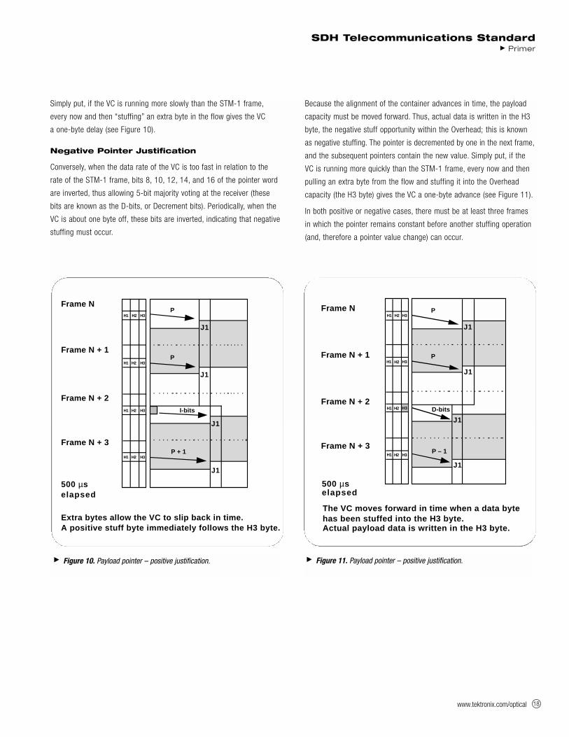
Positive Pointer Justification
When the data rate of the VC is too slow in relation to the rate of the
STM-1 frame, bits 7, 9, 11, 13, and 15 of the pointer word are inverted
in one frame, thus allowing 5-bit majority voting at the receiver (these
bits are known as the I-bits or Increment bits). Periodically, when the VC
is about one byte off, these bits are inverted, indicating that positive
stuffing must occur.
An additional byte is stuffed in, allowing
the alignment of the container to slip
back in time. This is known as positive
stuffing, and the stuff byte is made up
of non-information bits. The actual posi-
tive stuff byte immediately follows the
H3 byte (that is, the stuff byte is within
the VC portion). The pointer is incre-
mented by one in the next frame, and
the subsequent pointers contain the
new value.
SDH Telecommunications Standard Primer
Table 9. SDH Pointers
Byte Description
H1 and H2 Pointer bytes – These two bytes, the VC payload pointer, specify the location of the VC frame.It’s used to align the VC and STM-1 Section Overheads in an STM-N signal, to perform frequency justification, and to indicate STM-1 concatenation.
H3 Pointer action byte – This byte is used for frequency justification. Depending on the pointer value,the byte is used to adjust the fill input buffers. The byte only carries valid information in the event of negative justification, otherwise it’s not defined.
Figure 9. Pointer 9-byte structure.
3 X AU-3 H1 H1 H1 H2 H2 H2 H3 H3 H3
1 X AU-4 H1 Y Y H2 1 1 H3 H3 H31 = All 1s Y = 1001SS11(S bits unspecified)
www.tektronix.com/optical 18
Simply put, if the VC is running more slowly than the STM-1 frame,
every now and then “stuffing” an extra byte in the flow gives the VC
a one-byte delay (see Figure 10).
Negative Pointer Justification
Conversely, when the data rate of the VC is too fast in relation to the
rate of the STM-1 frame, bits 8, 10, 12, 14, and 16 of the pointer word
are inverted, thus allowing 5-bit majority voting at the receiver (these
bits are known as the D-bits, or Decrement bits). Periodically, when the
VC is about one byte off, these bits are inverted, indicating that negative
stuffing must occur.
Because the alignment of the container advances in time, the payload
capacity must be moved forward. Thus, actual data is written in the H3
byte, the negative stuff opportunity within the Overhead; this is known
as negative stuffing. The pointer is decremented by one in the next frame,
and the subsequent pointers contain the new value. Simply put, if the
VC is running more quickly than the STM-1 frame, every now and then
pulling an extra byte from the flow and stuffing it into the Overhead
capacity (the H3 byte) gives the VC a one-byte advance (see Figure 11).
In both positive or negative cases, there must be at least three frames
in which the pointer remains constant before another stuffing operation
(and, therefore a pointer value change) can occur.
SDH Telecommunications StandardPrimer
Figure 10. Payload pointer – positive justification.
H1 H2 H3
H1 H2 H3
H1 H2 H3
H1 H2 H3
Frame N + 1
Frame N
Frame N + 2
Frame N + 3
P
P
P + 1
500 µselapsed
J1
J1
J1
J1
Extra bytes allow the VC to slip back in time. A positive stuff byte immediately follows the H3 byte.
I-bits
Figure 11. Payload pointer – positive justification.
H1 H2 H3
H1 H2 H3
H1 H2
H1 H2 H3
Frame N + 1
Frame N
Frame N + 2
Frame N + 3
P
P
P – 1
500 µs elapsed
J1
J1
J1
J1
The VC moves forward in time when a data bytehas been stuffed into the H3 byte.Actual payload data is written in the H3 byte.
H3 D-bits
www.tektronix.com/optical19
SDH Multiplexing
The multiplexing principles of SDH follow, using these terms
and definitions:
Mapping – A process used when tributaries are adapted into Virtual
Containers (VCs) by adding justification bits and Path Overhead (POH)
information.
Aligning – This process takes place when a pointer is included in a Tributary
Unit (TU) or an Administrative Unit (AU), to allow the first byte of the Virtual
Container to be located.
Multiplexing – This process is used when multiple lower-order path layer
signals are adapted into a higher-order path signal, or when the higher-order
path signals are adapted into a Multiplex Section.
Stuffing – As the tributary signals are multiplexed and aligned, some spare
capacity has been designed into the SDH frame to provide enough space for
all the various tributary rates. Therefore, at certain points in the multiplexing
hierarchy, this space capacity is filled with “fixed stuffing” bits that carry no
information, but are required to fill up the particular frame.
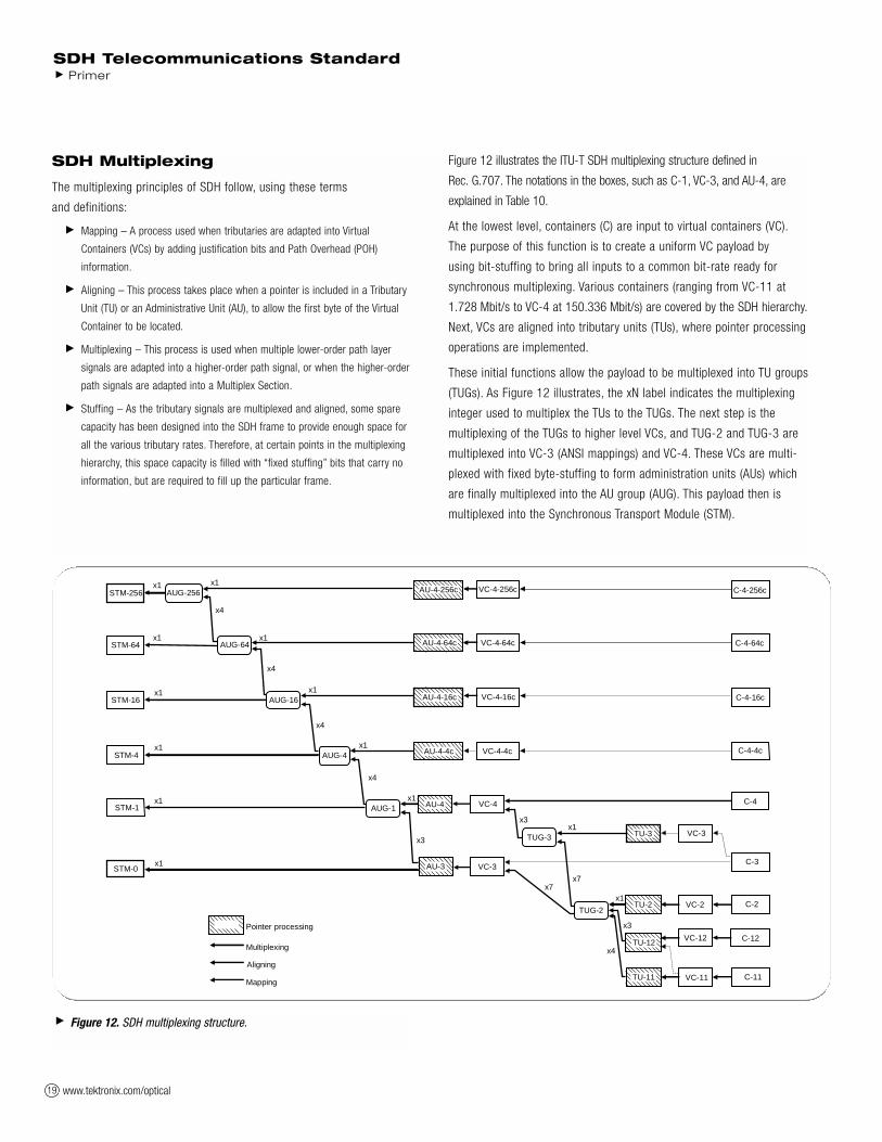
Figure 12 illustrates the ITU-T SDH multiplexing structure defined in
Rec. G.707. The notations in the boxes, such as C-1, VC-3, and AU-4, are
explained in Table 10.
At the lowest level, containers (C) are input to virtual containers (VC).
The purpose of this function is to create a uniform VC payload by
using bit-stuffing to bring all inputs to a common bit-rate ready for
synchronous multiplexing. Various containers (ranging from VC-11 at
1.728 Mbit/s to VC-4 at 150.336 Mbit/s) are covered by the SDH hierarchy.
Next, VCs are aligned into tributary units (TUs), where pointer processing
operations are implemented.
These initial functions allow the payload to be multiplexed into TU groups
(TUGs). As Figure 12 illustrates, the xN label indicates the multiplexing
integer used to multiplex the TUs to the TUGs. The next step is the
multiplexing of the TUGs to higher level VCs, and TUG-2 and TUG-3 are
multiplexed into VC-3 (ANSI mappings) and VC-4. These VCs are multi-
plexed with fixed byte-stuffing to form administration units (AUs) which
are finally multiplexed into the AU group (AUG). This payload then is
multiplexed into the Synchronous Transport Module (STM).
SDH Telecommunications Standard Primer
Figure 12. SDH multiplexing structure.
C-11VC-11TU-11
Aligning
Mapping
x1x1
x3
x3x1
x1
x3
x4
x7x7
STM-1 AUG-1 AU-4 VC-4
AU-3 VC-3
C-4
C-3
C-2
C-12
VC-3
VC-2
VC-12
TU-3
TU-2
TU-12
TUG-2
TUG-3
Pointer processing
Multiplexing
x4
x1x1STM-16 AUG-16 VC-4-16c
VC-4-4c
x1
x4
STM-64 AUG-64
x1x1
x4
STM-4C-4-4c
C-4-16c
x1STM-0
x1x1STM-256 VC-4-256c C-4-256c
x1VC-4-64c C-4-64c
AU-4-256c
AU-4-64c
AU-4-16c
AU-4-4c
AUG-256
AUG-4
x4
www.tektronix.com/optical 20
SDH Telecommunications StandardPrimer
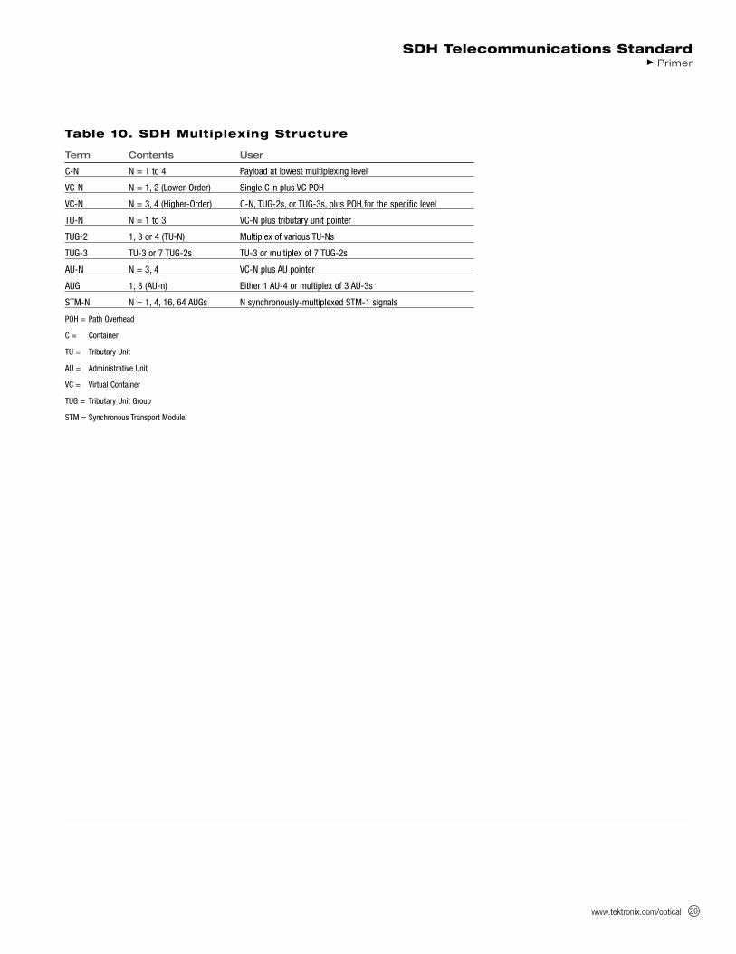
Table 10. SDH Multiplexing Structure
Term Contents User
C-N N = 1 to 4 Payload at lowest multiplexing level
VC-N N = 1, 2 (Lower-Order) Single C-n plus VC POH
VC-N N = 3, 4 (Higher-Order) C-N, TUG-2s, or TUG-3s, plus POH for the specific level
TU-N N = 1 to 3 VC-N plus tributary unit pointer
TUG-2 1, 3 or 4 (TU-N) Multiplex of various TU-Ns
TUG-3 TU-3 or 7 TUG-2s TU-3 or multiplex of 7 TUG-2s
AU-N N = 3, 4 VC-N plus AU pointer
AUG 1, 3 (AU-n) Either 1 AU-4 or multiplex of 3 AU-3s
STM-N N = 1, 4, 16, 64 AUGs N synchronously-multiplexed STM-1 signals
POH = Path Overhead
C = Container
TU = Tributary Unit
AU = Administrative Unit
VC = Virtual Container
TUG = Tributary Unit Group
STM = Synchronous Transport Module
www.tektronix.com/optical21
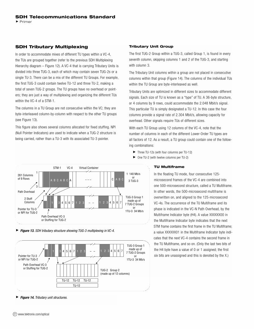
SDH Tributary Multiplexing
In order to accommodate mixes of different TU types within a VC-4,
the TUs are grouped together (refer to the previous SDH Multiplexing
Hierarchy diagram – Figure 12). A VC-4 that is carrying Tributary Units is
divided into three TUG-3, each of which may contain seven TUG-2s or a
single TU-3. There can be a mix of the different TU Groups. For example,
the first TUG-3 could contain twelve TU-12 and three TU-2, making a
total of seven TUG-2 groups. The TU groups have no overhead or point-
ers; they are just a way of multiplexing and organizing the different TUs
within the VC-4 of a STM-1.
The columns in a TU Group are not consecutive within the VC; they are
byte-interleaved column-by-column with respect to the other TU groups
(see Figure 13).
This figure also shows several columns allocated for fixed stuffing. NPI
(Null Pointer Indicators) are used to indicate when a TUG-2 structure is
being carried, rather than a TU-3 with its associated TU-3 pointer.
Tributary Unit Group
The first TUG-2 Group within a TUG-3, called Group 1, is found in every
seventh column, skipping columns 1 and 2 of the TUG-3, and starting
with column 3.
The Tributary Unit columns within a group are not placed in consecutive
columns within that group (Figure 14). The columns of the individual TUs
within the TU Group are byte-interleaved as well.
Tributary Units are optimized in different sizes to accommodate different
signals. Each size of TU is known as a “type” of TU. A 36-byte structure,
or 4 columns by 9 rows, could accommodate the 2.048 Mbit/s signal.
This particular TU is simply designated a TU-12. In this case the four
columns provide a signal rate of 2.304 Mbit/s, allowing capacity for
overhead. Other signals require TUs of different sizes.
With each TU Group using 12 columns of the VC-4, note that the
number of columns in each of the different Lower-Order TU types are
all factors of 12. As a result, a TU group could contain one of the follow-
ing combinations:
Three TU-12s (with four columns per TU-12)
One TU-2 (with twelve columns per TU-2)
TU Multiframe
In the floating TU mode, four consecutive 125-
microsecond frames of the VC-4 are combined into
one 500-microsecond structure, called a TU Multiframe.
In other words, the 500-microsecond multiframe is
overwritten on, and aligned to the 125-microsecond
VC-4s. The occurrence of the TU Multiframe and its
phase is indicated in the VC-N Path Overhead, by the
Multiframe Indicator byte (H4). A value XXXXXX00 in
the Multiframe Indicator byte indicates that the next
STM frame contains the first frame in the TU Multiframe;
a value XXXXXX01 in the Multiframe Indicator byte indi-
cates that the next VC-4 contains the second frame in
the TU Multiframe, and so on. (Only the last two bits of
the H4 byte have a value of 0 or 1 assigned; the first
six bits are unassigned and this is denoted by the X.)
SDH Telecommunications Standard Primer
Figure 13. SDH tributary structure showing TUG-3 multiplexing in VC-4.
STM-1 VC-4 Virtual Container
261 Columnsof 9 Rows
1 140 Mb/sor
3 TUG-3
Path Overhead
2 Stuff Columns
Pointer for TU-3or NPI for TUG-2
Path Overhead VC-3or Stuffing for TUG-2
TUG-3 Group 1made up of
7 TUG-2 Groupsor
1TU-3 34 Mb/s
1
3
A B C A B C A C A B C
1 3 4 5 6 7 1 2 3 – – 1 2 3 4 5 6 7
– – –
Figure 14. Tributary unit structures.
Pointer for TU-3or NPI for TUG-2
Path Overhead VC-3or Stuffing for TUG-2
TUG-3 Group 1made up of
7 TUG-2 Groupsor
1TU-3 34 Mb/s
1 3 4 5 6 7 1 2 3 – – 1 2 3 4 5 6 7
TUG-2 Group 2(made up of 12 columns)
TU-12 TU-12 TU-12
TU-12
www.tektronix.com/optical 22
The Tributary Units also contain payload pointers to allow for flexible and
dynamic alignment of the VC. In this case, the TU pointer value indicates
the offset from the TU to the first byte of the VC. TU pointers allow AU
and TU payloads to differ in phase with respect to each other and the
network while still allowing AUs and TUs to be synchronously multiplexed.
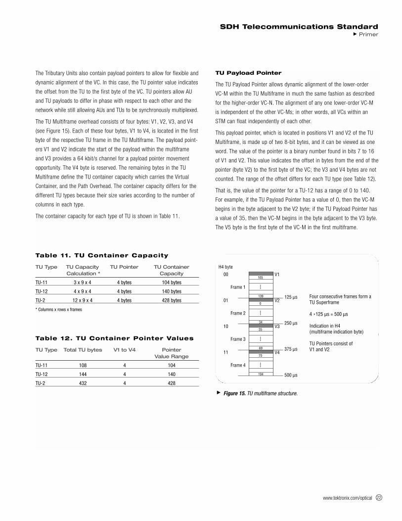
The TU Multiframe overhead consists of four bytes: V1, V2, V3, and V4
(see Figure 15). Each of these four bytes, V1 to V4, is located in the first
byte of the respective TU frame in the TU Multiframe. The payload point-
ers V1 and V2 indicate the start of the payload within the multiframe
and V3 provides a 64 kbit/s channel for a payload pointer movement
opportunity. The V4 byte is reserved. The remaining bytes in the TU
Multiframe define the TU container capacity which carries the Virtual
Container, and the Path Overhead. The container capacity differs for the
different TU types because their size varies according to the number of
columns in each type.
The container capacity for each type of TU is shown in Table 11.
TU Payload Pointer
The TU Payload Pointer allows dynamic alignment of the lower-order
VC-M within the TU Multiframe in much the same fashion as described
for the higher-order VC-N. The alignment of any one lower-order VC-M
is independent of the other VC-Ms; in other words, all VCs within an
STM can float independently of each other.
This payload pointer, which is located in positions V1 and V2 of the TU
Multiframe, is made up of two 8-bit bytes, and it can be viewed as one
word. The value of the pointer is a binary number found in bits 7 to 16
of V1 and V2. This value indicates the offset in bytes from the end of the
pointer (byte V2) to the first byte of the VC; the V3 and V4 bytes are not
counted. The range of the offset differs for each TU type (see Table 12).
That is, the value of the pointer for a TU-12 has a range of 0 to 140.
For example, if the TU Payload Pointer has a value of 0, then the VC-M
begins in the byte adjacent to the V2 byte; if the TU Payload Pointer has
a value of 35, then the VC-M begins in the byte adjacent to the V3 byte.
The V5 byte is the first byte of the VC-M in the first multiframe.
SDH Telecommunications StandardPrimer
Figure 15. TU multiframe structure.
Four consecutive frames TU Superframe
4 *125 µs = 500 µs
Indication in H4(multiframe indication by
TU Pointers consist ofV1 and V2
Frame 1
H4 byte
00105
V1
---
139 125 µs
Frame 2
010
V2
---
34 250 µs
Frame 3
1035
V3
---
69 375 µs
Frame 4
1170
V4
---
104 500 µs
Table 12. TU Container Pointer Values
TU Type Total TU bytes V1 to V4 PointerValue Range
TU-11 108 4 104
TU-12 144 4 140
TU-2 432 4 428
Table 11. TU Container Capacity
TU Type TU Capacity TU Pointer TU Container Calculation * Capacity
TU-11 3 x 9 x 4 4 bytes 104 bytes
TU-12 4 x 9 x 4 4 bytes 140 bytes
TU-2 12 x 9 x 4 4 bytes 428 bytes
* Columns x rows x frames
Four consecutive frames form a TU Superframe
4 *125 µs = 500 µs
Indication in H4(multiframe indication byte)
TU Pointers consist ofV1 and V2
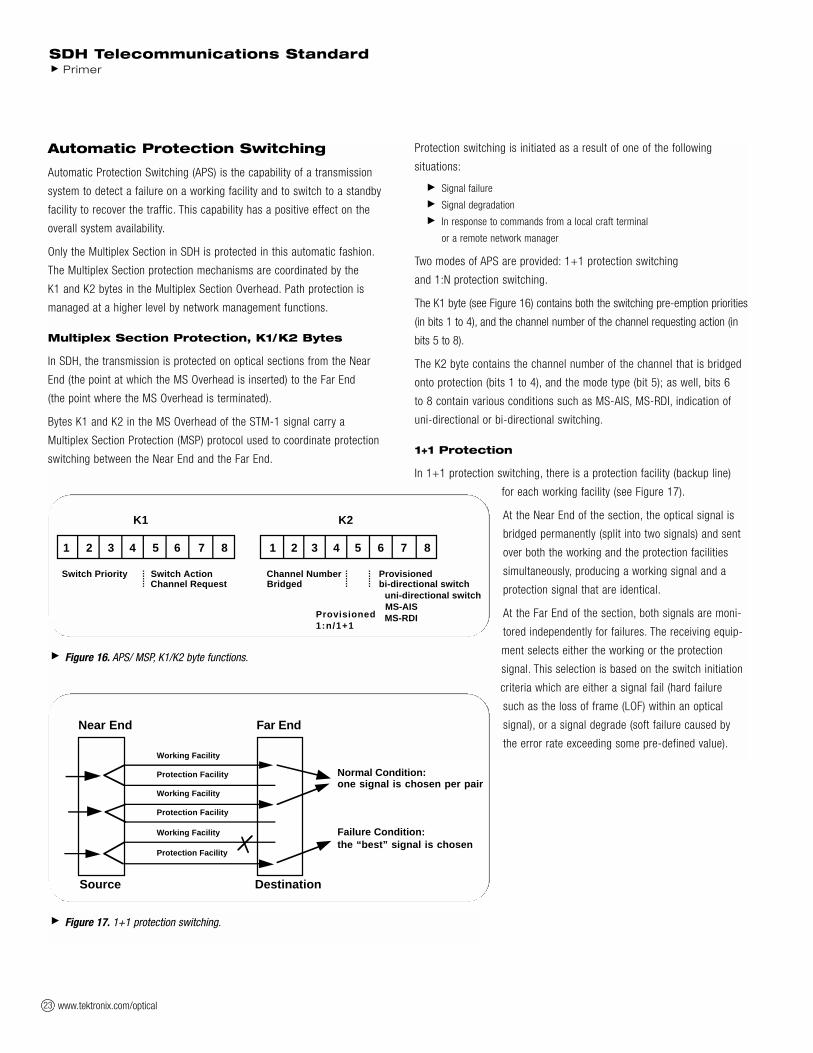
www.tektronix.com/optical23
Automatic Protection Switching
Automatic Protection Switching (APS) is the capability of a transmission
system to detect a failure on a working facility and to switch to a standby
facility to recover the traffic. This capability has a positive effect on the
overall system availability.
Only the Multiplex Section in SDH is protected in this automatic fashion.
The Multiplex Section protection mechanisms are coordinated by the
K1 and K2 bytes in the Multiplex Section Overhead. Path protection is
managed at a higher level by network management functions.
Multiplex Section Protection, K1/K2 Bytes
In SDH, the transmission is protected on optical sections from the Near
End (the point at which the MS Overhead is inserted) to the Far End
(the point where the MS Overhead is terminated).
Bytes K1 and K2 in the MS Overhead of the STM-1 signal carry a
Multiplex Section Protection (MSP) protocol used to coordinate protection
switching between the Near End and the Far End.
Protection switching is initiated as a result of one of the following
situations:
Signal failure
Signal degradation
In response to commands from a local craft terminal
or a remote network manager
Two modes of APS are provided: 1+1 protection switching
and 1:N protection switching.
The K1 byte (see Figure 16) contains both the switching pre-emption priorities
(in bits 1 to 4), and the channel number of the channel requesting action (in
bits 5 to 8).
The K2 byte contains the channel number of the channel that is bridged
onto protection (bits 1 to 4), and the mode type (bit 5); as well, bits 6
to 8 contain various conditions such as MS-AIS, MS-RDI, indication of
uni-directional or bi-directional switching.
1+1 Protection
In 1+1 protection switching, there is a protection facility (backup line)
for each working facility (see Figure 17).
At the Near End of the section, the optical signal is
bridged permanently (split into two signals) and sent
over both the working and the protection facilities
simultaneously, producing a working signal and a
protection signal that are identical.
At the Far End of the section, both signals are moni-
tored independently for failures. The receiving equip-
ment selects either the working or the protection
signal. This selection is based on the switch initiation
criteria which are either a signal fail (hard failure
such as the loss of frame (LOF) within an optical
signal), or a signal degrade (soft failure caused by
the error rate exceeding some pre-defined value).
SDH Telecommunications Standard Primer
Figure 16. APS/ MSP, K1/K2 byte functions.
K1 K2
1 2 3 4 5 6 7 8 1 2 3 4 5 6 7 8
Switch Priority Switch Action Channel Number Provisioned Channel Request Bridged bi-directional switch
uni-directional switch MS-AIS MS-RDIProvisioned1:n/1+1
Figure 17. 1+1 protection switching.
Near End Far End
Source Destination
Normal Condition:one signal is chosen per pair
Failure Condition:the “best” signal is chosen
Working Facility
Protection Facility
Working Facility
Protection Facility
Working Facility
Protection Facility

www.tektronix.com/optical 24
Normally, 1+1 protection switching is uni-directional, although if the line
terminating equipment at both ends support bi-directional switching, the
uni-directional default can be overridden.
Switching can be either revertive (the flow reverts to the working facility
as soon as the failure has been corrected) or non-revertive (the protec-
tion facility is treated as the working facility).
In 1+1 protection architecture, all communication from the Near End to
the Far End is carried out over the APS channel, using the K1 and K2
bytes. In 1:1 bi-directional switching, the K-byte signaling indicates to
the Near End that a facility has been switched so that it can start to
receive on the now active facility.
1:N Protection
In 1:N protection switching, there is one protection facility for several
working facilities (the range is from 1 to 14). In 1:N protection architec-
ture, all communication from the Near End to the Far End is carried out
over the APS channel, using the K1 and K2 bytes. All switching is
revertive; that is, the traffic reverts to the working facility as soon as
the failure has been corrected.
In 1:N protection switching, optical signals are normally sent only over
the working facilities, with the protection facility being kept free until a
working facility fails. Let’s look at a failure in a bi-directional architec-
ture (see Figure 18). Suppose the Far End detects a failure on working
facility 2. The Far End sends a message in bits 5 to 8 of the K1 byte to
the Near End over the protection facility requesting switch action. The
Near End can act directly, or if there’s more than one problem, the Near
End decides which is top priority. On a decision to act on the problem
on working facility 2, the Near End carries out the following steps:
1. Bridges working facility 2 at the Near End to the protection facility.
2. Returns a message on the K2 byte indicating the channel number of
the traffic on the protection channel to the Far End.
3. Sends a Reverse Request to the Far End via the K1 byte to initiate
bi-directional switch.
On receipt of this message, the Far End carries out the following steps:
1. Switches to the protection facility to receive.
2. Bridges working facility 2 to the protection facility to transmit back.
Now transmission is carried out over the new working facility.
SDH Telecommunications StandardPrimer
Figure 18. 1:N protection switching.
Near End Far End
Source Destination
Normal Condition:protection on channel empty
Failure Condition:protection channel containsfailed line
Working Facility
Protection Facilty
Working Facility
Protection Facility
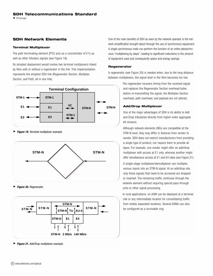
www.tektronix.com/optical25
SDH Network Elements
Terminal Multiplexer
The path terminating element (PTE) acts as a concentrator of E1s as
well as other tributary signals (see Figure 19).
Its simplest deployment would involve two terminal multiplexers linked
by fibre with or without a regenerator in the link. This implementation
represents the simplest SDH link (Regenerator Section, Multiplex
Section, and Path, all in one link).
One of the main benefits of SDH as seen by the network operator is the net-
work simplification brought about through the use of synchronous equipment.
A single synchronous node can perform the function of an entire plesiochro-
nous “multiplexing by steps”, leading to significant reductions in the amount
of equipment used and consequently space and energy savings.
Regenerator
A regenerator (see Figure 20) is needed when, due to the long distance
between multiplexers, the signal level in the fibre becomes too low.
The regenerator recovers timing from the received signal
and replaces the Regenerator Section overhead bytes
before re-transmitting the signal; the Multiplex Section
overhead, path overhead, and payload are not altered.
Add/Drop Multiplexer
One of the major advantages of SDH is its ability to Add
and Drop tributaries directly from higher-order aggregate
bit streams.
Although network elements (NEs) are compatible at the
STM-N level, they may differ in features from vendor to
vendor. SDH does not restrict manufacturers from providing
a single type of product, nor require them to provide all
types. For example, one vendor might offer an add/drop
multiplexer with access at E1 only, whereas another might
offer simultaneous access at E1 and E4 rates (see Figure 21).
A single-stage multiplexer/demultiplexer can multiplex
various inputs into an STM-N signal. At an add/drop site,
only those signals that need to be accessed are dropped
or inserted. The remaining traffic continues through the
network element without requiring special pass-through
units or other signal processing.
In rural applications, an ADM can be deployed at a terminal
site or any intermediate location for consolidating traffic
from widely separated locations. Several ADMs can also
be configured as a survivable ring.
SDH Telecommunications Standard Primer
Figure 19. Terminal multiplexer example.
E1
E3
STM-NVC
STM-1
E1
E3
STM-N
STM-1
Terminal Configuration
STM-1
Figure 20. Regenerator.
STM-NSTM-N
Figure 21. Add/Drop multiplexer example.
STM-N
STM-N
STM-N E1 E4
2 Mb/s 140 Mb/s
AU-4TUSTM-NSTM-N
STM-N
STM-N

www.tektronix.com/optical 26
SDH enables drop-and-continue, a key capability in both telephony and cable
TV applications. With drop-and-continue, a signal terminates at one node, is
duplicated, and is then sent to the next node and to subsequent nodes.
In ring-survivability applications, drop-and-continue provides alternate
routing for traffic passing through interconnecting rings in a “matched-
nodes” configuration. If the connection cannot be made through one of
the nodes, the signal is repeated and passed along an alternate route to
the destination node.
In multi-node distribution applications, one transport channel can efficiently
carry traffic between multiple distribution nodes. When transporting video, for
example, each programming channel is delivered (dropped) at the node and
repeated for delivery to the next and subsequent nodes. Not all bandwidth (pro-
gram channels) need be terminated at all the nodes. Channels not terminating
at a node can be passed through without physical intervention to other nodes.
Wideband Digital Cross-connect
An SDH cross-connect accepts various SDH rates, accesses the STM-1
signals, and connects payloads, for example, at a TU-12 level (see
Figure 22). One major difference between a cross-connect and an add-
drop multiplexer is that a cross-connect may be used to interconnect
a much larger number of STM-1s. The cross-connect can be used for
grooming (consolidating or segregating) of STM-1s or for broadband
traffic management. For example, it may be used to segregate high-
bandwidth from low-bandwidth traffic and send them separately to the
high-bandwidth (for example video) switch and a low-bandwidth (voice)
switch. It supports hubbed network architectures.
This type of cross-connect is similar to the broadband cross-connect
except that the switching is done at TU-12 level. It is suitable for E1
level grooming applications at cross-connect locations. One major
advantage of wideband digital cross-connects is that less
demultiplexing and multiplexing is required because only
the required tributaries are accessed and switched.
Broadband Digital Cross-connect
The Broadband Digital Cross-connect interfaces SDH
signals and possibly high-rate tributaries (see Figure 23).
It accesses the STM-N signals, and typically switches at
an AU-4 level.
It’s best used as an SDH cross-connect, where it can be used
for grooming STM-1s, for broadband restoration purposes,
or for routing traffic.
SDH Telecommunications StandardPrimer
Figure 22. Wideband digital cross-connect example.
STM-1 2 Mb/s 140 Mb/sSTM-NSTM-N
STM-1 E1 E4STM-N
TU-12TU-12TU-12TU-12
TU-12 Switch Matrix
Figure 23. Broadband digital cross-connect example.
140 Mb/sSTM-N
STM-N E1 E4STM-N
AU-4AU-4
Transparent Switch Matrix
STM-N STM-1 2 Mb/s
AU-4 AU-4

www.tektronix.com/optical27
Flexible Multiplexer
The Flexible Multiplexer (see Figure 24) may be considered a concentra-
tor of low-speed services before they are brought into the local exchange
for distribution. If this concentration were not done, the number of sub-
scribers (or lines) that an exchange could serve would be limited by the
number of lines served by the exchange. The Flexible Multiplexer itself
is actually a system of multiplexers and switches designed to perform
some traffic concentration and limited switching at a remote location.
SDH Network Configurations
Point-to-Point
The simplest network configuration involves two terminal multiplexers
linked by fibre with or without a regenerator in the link (see Figure 25).
In this configuration, the SDH path and the Service path (for example,
E1 or E3 links end-to-end) are identical and this synchronous island can
exist within an asynchronous network world. In the future, point-to-point
service path connections will span across the whole network and will
always originate and terminate in a multiplexer.
Point-to-Multipoint
A point-to-multipoint (linear add/drop) architec-
ture includes adding and dropping circuits along
the way (see Figure 26). The SDH ADM (add/drop
multiplexer) is a unique network element specifi-
cally designed for this task. It avoids the current
cumbersome network architecture of demulti-
plexing, cross-connecting, adding and dropping
channels, and then re-multiplexing. The ADM
typically is placed in an SDH link to facilitate
adding and dropping tributary channels at inter-
mediate points in the network.
SDH Telecommunications Standard Primer
Figure 25. Point-to-point.
PTEPTE REG
Figure 26. Point-to-multipoint.
REGPTE ADM PTEREG
Figure 24. Flexible multiplexer example.
ExchangeSwitch
64 kb/s
STM-1
RemoteLocations(subscribers)64 kb/s
SDHConcen-trator SDH
Concen-trator
Exchange
VoiceDataISDNPublic Phone

www.tektronix.com/optical 28
Mesh Architecture
The meshed network architecture accommodates unexpected growth
and change more easily than simple point-to-point networks. A cross-
connect function concentrates traffic at a central site and allows easy
re-provisioning of the circuits (see Figure 27).
There are two possible implementations of this type of network function:
1. Cross-connection at higher-order path levels, for example, using AU-4
granularity in the switching matrix.
2. Cross-connection at lower-order path levels, for example, using TU-12
granlarity in the switching matrix.
Ring Architecture
The SDH building block for a ring architecture is the ADM (see Figure 28).
Multiple ADMs can be put into a ring configuration for either Bi-direc-
tional or Uni-directional traffic. The main advantage of the ring topology
is its survivability; if a fibre cable is cut, for example, the multiplexers
have the local intelligence to send the services affected via an alternate
path through the ring without a lengthy interruption.
The demand for survivable services, diverse routing of fibre facilities,
flexibility to rearrange services to alternate serving nodes, as well as
automatic restoration within seconds, have made rings a popular
SDH topology.
SDH Telecommunications StandardPrimer
Figure 27. Mesh architecture.
MUX
MUX
MUX
MUXDCS
REG
REGREG
REG
Figure 28. Ring architecture.
ADM
ADM
ADM
ADM

www.tektronix.com/optical29
Benefits of SDH – Conclusions
A transport network using SDH provides much more powerful networking
capabilities than existing asynchronous systems. The key benefits pro-
vided by SDH are the following.
Pointers, MUX/DEMUX
As a result of SDH transmission, the network clocks are referenced to
a highly stable reference point; so the need to align the data streams
using non-deterministic bit-stuffing is unnecessary. Therefore, a lower
rate channel such as E1 is directly accessible, and intermediate demulti-
plexing is not needed to access the bitstreams.
For those situations in which synchronisation reference frequency and
phase may vary, SDH uses pointers to allow the streams to “float” within
the payload. Pointers are the key to synchronous timing; they allow a
very flexible allocation and alignment of the payload within the transmis-
sion frame.
Reduced Back-to-Back Multiplexing
In the asynchronous PDH systems, care must be taken when routing
circuits in order to avoid multiplexing and demultiplexing too many times
since electronics (and their associated capital cost) are required every
time an E1 signal is processed. With SDH, E1s can be multiplexed
directly to the STM-N rate. Because of synchronisation, an entire optical
signal doesn’t have to be demultiplexed – only the individual VC or STM
signals that need to be accessed.
Optical Interconnect
A major SDH benefit is that it allows mid-span meet with multi-vendor
compatibility. Today’s SDH standards contain definitions for fibre-to-fibre
interfaces at the physical level. They determine the optical line rate,
wavelength, power levels, pulse shapes, and coding. The current standards
also fully define the frame structure, overhead, and payload mappings.
Enhancements are being developed to define the messages in the over-
head channels to provide increased OAM functionality.
SDH allows optical interconnection between network providers regardless
of who makes the equipment. The network provider can purchase one
vendor’s equipment and conveniently interface with other vendors’ SDH
equipment at either operator locations or customer premises. Users may
now obtain the STM-N equipment of their choice and meet with their
network provider of choice at that STM-N level.
Multi-point Configurations
Most existing asynchronous transmission systems are only economic
for point-to-point applications, whereas SDH can efficiently support a
multi-point or cross-connected configuration.
The cross-connect allows many nodes or sites to communicate as a
single network instead of as separate systems. Cross-connecting
reduces requirements for back-to-back multiplexing and demultiplexing,
and helps realize the benefits of traffic grooming.
Network providers no longer need to own and maintain customer-located
equipment. A multi-point implementation permits STM-N interconnects
and mid-span meets, allowing network providers and their customers to
optimize their shared use of the SDH infrastructure.
Grooming
Grooming refers to either consolidating or segregating traffic to make
more efficient use of the network facilities. Consolidation means combin-
ing traffic from different locations onto one facility, while segregation is
the separation of traffic.
Grooming eliminates inefficient techniques such as back-hauling. It’s
possible to groom traffic on asynchronous systems, however to do so
requires expensive back-to-back configurations and manual or electronic
cross-connects. By contrast, an SDH system can segregate traffic at
either an STM-1 or VC level to send it to the appropriate nodes.
Grooming can also provide segregation of services. For example, at an
interconnect point, an incoming SDH line may contain different types of
traffic, such as switched voice, leased circuits for data, or video. An SDH
network can conveniently segregate the switched and non-switched traffic.
Enhanced OAM
SDH allows integrated network OAM, in accordance with the philosophy
of single-ended maintenance. In other words, one connection can reach
all network elements within a given architecture; separate links are
not required for each network element. Remote provisioning provides
centralized maintenance and reduced travel for maintenance personnel –
which translates to expense savings.
Note: OAM is sometimes referred to as OAM&P.
SDH Telecommunications Standard Primer

www.tektronix.com/optical 30
Enhanced Performance Monitoring
Substantial overhead information is provided in SDH to allow quicker
troubleshooting and detection of failures before they degrade to
serious levels.
Convergence, ATM, IP, Video, and SDH
Convergence is the trend toward delivery of voice, data, images, and
video through diverse transmission and switching systems that supply
high-speed transportation over any medium to any location. Tektronix is
pursuing new opportunities to lead the market by providing test and
measurement equipment to users who process or transport voice, data,
image, and video signals over high-speed networks.
Some broadband services may use Asynchronous Transfer Mode (ATM) –
a fast packet-switching technique using short, fixed-length packets
called cells. Asynchronous Transfer Mode multiplexes a service into cells
that may be combined and routed as necessary. Because of the capacity
and flexibility that it offers, SDH is a logical transport mechanism for
ATM. As local and wide area networks converge, Packet over SDH (PoS)
technologies allow the transport of IP packets at SDH rates.
In principle, ATM is quite similar to other packet-switching techniques;
however, the detail of ATM operation is somewhat different. Each ATM
cell is made up of 53 octets, or bytes (see Figure 29). Of these, 48
octets make up the user-information field and five octets make up the
header. The cell header identifies the “virtual path” to be used in routing
the cell through the network. The virtual path defines the connections
through which the cell is routed to reach its destination (see Figure 30).
A Packet-based network is bandwidth-flexible, which allows handling
of a dynamically variable mixture of services at different bandwidths.
Packet networks also easily accommodate traffic of variable speeds.
An example of a service that realizes the benefits of a variable-rate
interface is that of a video service, where video can be digitally coded
and packetised within ATM or IP cells.
The rate at which cells can be transmitted through the network is
dependent upon the physical layer of the network used for transport
of the cells. The interface rate presented to the user may vary between
a minimum and maximum rate, which ensures a much more efficient
use of the bandwidth made available to the end user.
SDH Telecommunications StandardPrimer
Figure 29. ATM cell structure.
The ATM cell consists of two parts: a five-byte header and a 48-byte information field.
GFC (UNI) orVPI (NNI) VPI
VPI VCI5
VCIByte
VCI PT CLPHeader
HEC
(48 bytes) (Payload) USERINFO
GFC:
VCI: Virtual Channel Identifier PTI: Payload Type IndicatorVPI: Virtual Path Identifier CLP: Cell Loss PriorityHEC: Header Error Check Generic Flow Control
Figure 30. ATM SDH mapping.
261
AU-4
9
VC-4TransportOverhead
TransportOverhead
AU-4 Pointer
53 Byte ATM Cell
VC-4 POH
J1B3C2G1F2H4F3K3N1
3
5

www.tektronix.com/optical31
SONET Reference
Transmission standards in the U.S., Canada, Korea, Taiwan, and Hong Kong
(ANSI) and the rest of the world (ITU-T) evolved from different basic-rate sig-
nals in the non-synchronous hierarchy. ANSI Time Division Multiplexing (TDM)
combines twenty four 64 kbit/s channels (DS0) into one 1.544 Mbit/s DS1
signal. ITU TDM multiplexes thirty 64 kbit/s channels (E0) into one 2.048 Mbit/s
E1 signal (an extra two channels provide frame alignment and signalling,
making 32 total).
An important issue for the ITU-T to resolve was how to efficiently accommo-
date both the 1.5 Mbit/s and the 2 Mbit/s non-synchronous hierarchies in a
single network standard. The agreement reached specified a basic transmis-
sion rate of 51 Mbit/s for SONET and a basic rate of 155 Mbit/s for SDH.
Synchronous and non-synchronous line rates and the relationships
between each are shown in Tables 13 and 14.
SONET and SDH Hierarchies
SONET and SDH converge at SDH’s 155 Mbit/s base level, defined as STM-1
or “Synchronous Transport Module-1.” The base level for SONET is STS-1
(or OC-1) and is equivalent to 51.84 Mbit/s. Thus, SDH’s STM-1 is equivalent
to SONET’s STS-3 (3 x 51.84 Mbit/s = 155.52 Mbit/s). Higher SDH rates of
STM-4 (622 Mbit/s), STM-16 (2.4 Gbit/s), and STM-64 (10 Gbit/s) have also
been defined.
Multiplexing is accomplished by combining – or interleaving – multiple
lower-order signals (1.5 Mbit/s, 2 Mbit/s, etc.) into higher-speed circuits
(51 Mbit/s, 155 Mbit/s, etc.). By changing the SONET standard from bit-
interleaving to byte-interleaving, it became possible for SDH to accommo-
date both transmission hierarchies. This modification allows an STM-1 signal
to carry multiple 1.5 Mbit/s or 2 Mbit/s signals – and multiple STM signals
to be aggregated to carry higher orders of SONET or SDH tributaries.
Further Information
Another publication from Tektronix, SONET Telecommunications
Standard Primer reviews the SONET network standard. Copies can be
requested from Tektronix offices, or visit our website at www.tektronix.com.
SDH Telecommunications Standard Primer
Table 13. SONET/SDH Digital Hierarchies
SONET Bit Rate SDH SONET Capacity SDH Capacity
STS-1, OC-1 51.84 Mbit/s STM-0 28 DS1 or 1 DS3 21 E1
STS-3, OC-3 155.52 Mbit/s STM-1 84 DS1 or 3 DS3 63 E1 or 1 E4
STS-12, OC-12 622.08 Mbit/s STM-4 336 DS1 or 12 DS3 252 E1 or 4 E4
STS-48, OC-48 2488.32 Mbit/s STM-16 1344 DS1 or 48 DS3 1008 E1 or 16 E4
STS-192, OC-192 9953.28 Mbit/s STM-64 5376 DS1 or 192 DS3 4032 E1 or 64 E4
STS-768, OC-768 39812.12 Mbit/s STM-256 21504 DS1s or 768 DS3s 16128 E1 or 256 E4
Note: Although an SDH STM-1 has the same bit rate as the SONET STS-3, the two signals contain different frame structures.
STM = Synchronous Transport Module (ITU-T)
STS = Synchronous Transport Signal (ANSI)
OC = Optical Carrier (ANSI)
Table 14. Non-Synchronous Digital Hierarchies
ANSI Rate ITU Rate
Signal Digital Bit Rate Channels Signal Digital Bit Rate Channels
DS0 64 kbit/s 1 DS0 E0 64 kbit/s 64 kbit/s
DS1 1.544 Mbit/s 24 DS0 E1 2.048 Mbit/s 32 E0
DS2 6.312 Mbit/s 96 DS0 E2 8.448 Mbit/s 128 E0
DS3 44.736 Mbit/s 28 DS1 E3 34.368 Mbit/s 16 E1
not defined E4 139.264 Mbit/s 64 E1

www.tektronix.com/optical 32
Glossary
Add/Drop
The process where a part of the information carried in a transmission
system is extracted (dropped) at an intermediate point and different
information is inserted (added) for subsequent transmission. The
remaining traffic passes straight through the multiplexer without
additional processing.
Add/Drop Multiplexer (ADM)
A multiplexer capable of extracting and inserting lower-rate signals
from a higher-rate multiplexed signal without completely demulti-
plexing the signal.
Administrative Unit (AU)
An Administrative Unit is the information structure which provides
adaptation between the Higher-Order path layer and the Multiplex
Section layer. The Virtual Container (VC) plus the pointers (H1, H2, H3
bytes) is called the Administrative Unit (AU).
AIS (Alarm Indication Signal)
A code sent downstream indicating an upstream failure has occurred.
AMI
Alternate Mark Inversion. The line-coding format in transmission
systems where successive ones (marks) are alternatively inverted
(sent with polarity opposite that of the preceding mark).
ANSI
American National Standards Institute. A standards-setting, non-
government organization, which develops and publishes standards
for “voluntary” use in the United States.
Asynchronous
A network where transmission system payloads are not synchronised
and each network terminal runs on its own clock.
Asynchronous Transfer Mode (ATM)
A multiplexing/switching technique in which information is organized
into fixed-length cells with each cell consisting of an identification
header field and an information field. The transfer mode is asynchro-
nous in the sense that the use of the cells depends on the required
or instantaneous bit rate.
Attenuation
Reduction of signal magnitude or signal loss, usually expressed
in decibels.
Automatic Protection Switching (APS)
The ability of a network element to detect a failed working line and
switch the service to a spare (protection) line. 1+1 APS pairs a pro-
tection line with each working line. 1:N APS provides one protection
line for every N working lines.
Backhauling
Cumbersome traffic management technique used to reduce the
expense of multiplexing/demultiplexing.
Bandwidth
Information-carrying capacity of a communication channel. Analog
bandwidth is the range of signal frequencies that can be transmitted
by a communication channel or network.
Bi-directional
Operating in both directions. Bi-directional APS allows protection
switching to be initiated by either end of the line.
Binary N-Zero Suppression (BNZS)
Line coding system that replaces N number of zeros with a special
code to maintain pulse density required for clock recovery. N is
typically 3, 6, or 8.
SDH Telecommunications StandardPrimer
Three sets of terms are often used inter-
changeably to describe SDH processes.
However, it’s important to recognize that these
terms are not equivalent; each has a distinct
meaning:
Add/Drop – The process where a part of the
information carried in a transmission system
is extracted (dropped) at an intermediate point
and different information is inserted (added)
for subsequent transmission. The remaining
traffic passes straight through the multiplexer
without additional processing.
Map/Demap – A term for multiplexing, implying
more visibility inside the resultant multiplexed bit
stream than available with conventional asynchro-
nous techniques.
Multiplex/Demultiplex – Multiplex (MUX)
allows the transmission of two or more signals over
a single channel. Demultiplex (DEMUX) is the
process of separating two or more signals previously
combined by compatible multiplexing equipment to
recover signals combined within it and for restoring
the distinct individual channels of the signals.
Don’t Confuse The Terms

www.tektronix.com/optical33
BIP-8 (Bit Interleaved Parity-8)
A method of error checking in SDH which allows in-service perform-
ance monitoring. For example, a BIP-8 creates eight-bit (one-byte)
groups, then does a parity check for each of the eight bit positions
in the byte.
B-ISDN (Broadband Integrated Services Digital Network)
A single ISDN network which can handle voice, data, and eventually
video services.
Bit
One binary digit; a pulse of data.
Bit Error Rate (BER)
The number of bit errors detected in a unit of time, usually one
second. Bit Error rate (BER) is calculated with the formula:
BER = errored bits received/total bits sent
Block Error rate (BLER)
One of the underlying concepts of error performance is the notion
of Errored Blocks; i.e., blocks in which one or more bits are in error.
A block is a set of consecutive bits associated with the path or section
monitored by means of an Error Detection Code (EDC), such as Bit
Interleaved Parity (BIP). Block Error rate (BLER) is calculated with
the formula:
BLER = errored blocks received/total blocks sent
Bit-Interleaved Parity (BIP)
A parity check that groups all the bits in a block into units (such as
byte), then performs a parity check for each bit position in the group.
Bit-Stuffing
In asynchronous systems, a technique used to synchronise asynchro-
nous signals to a common rate before multiplexing.
Bits per second (bit/s)
The number of bits passing a point every second. The transmission
rate for digital information.
Broadband
Services requiring over 2 Mbit/s transport capacity.
CCITT
Former name of ITU.
Channel
The smallest subdivision of a circuit that provides a type of communi-
cation service; usually a path with only one direction.
Circuit
A communications path or network; usually a pair of channels
providing bi-directional communication.
Circuit Switching
Basic switching process whereby a circuit between two users is
opened on demand and maintained for their exclusive use for the
duration of the transmission.
Coding Violation (CV)
A transmission error detected by the difference between the
transmitted line code and that expected at the receive end by the
logical coding rules.
Concatenation
The linking together of various data structures, for example two
channels joined to form a single channel. In SDH, a number (M) of
TUs can be linked together to produce a concatenated container, M
times the size of the TU. An example of this is the concatenation of
five TU-2s to carry a 32 Mbit/s video signal, known as VC-2-5c.
Once assembled, any concatenated VC structure is multiplexed,
switched, and transported through the network as a single entity.
Cyclic Redundancy Check (CRC)
A technique for using overhead bits to detect transmission errors.
Data Communications Channel (DCC)
Data channels in SDH that enable OAM communications between
intelligent controllers and individual network nodes as well as inter-
node communications.
Defect
A limited interruption in the ability of an item to perform a required
function. Persistence of a defect can cause a failure.
Demultiplex (DEMUX)
To separate two or more signals previously combined by compatible
multiplexing equipment to recover signals combined within it and for
restoring the distinct individual channels of the signals.
Dense Wavelength Division Multiplexing (DWDM)
DWDM is the higher capacity version of WDM, which is a means
of increasing the capacity of fibre-optic data transmission systems
through the multiplexing of multiple wavelengths of light. Commercially
available DWDM systems support the multiplexing of from 8 to 40
wavelengths of light.
Digital Cross-connect (DCS)
An electronic cross-connect which has access to lower-rate channels
in higher-rate multiplexed signals and can electronically rearrange
(cross-connect) those channels.
Digital Signal
An electrical or optical signal that varies in discrete steps. Electrical
signals are coded as voltages, optical signals are coded as pulses
of light.
SDH Telecommunications Standard Primer

www.tektronix.com/optical 34
ETSI (European Telecommunications Standards Institute)
Organization responsible for defining and maintaining European
standards, including SDH.
Failure
A termination of the ability of an item to perform a required function.
A failure is caused by the persistence of a defect.
FEBE (Far End Block Error)
See Remote Error Indication (REI).
FERF (Far End Receive Failure)
See Remote Defect Indication (RDI).
Fixed Stuff
A bit or byte whose function is reserved. Fixed stuff locations, some-
times called reserved locations, do not carry overhead or payload.
Floating Mode
A tributary mode that allows the synchronous payload to begin any-
where in the VC. Pointers identify the starting location of the LO-VC.
LO-VCs in different multiframes may begin at different locations.
Framing
Method of distinguishing digital channels that have been multiplexed
together.
Frequency
The number of cycles of periodic activity that occur in a discrete
amount of time.
Grooming
Consolidating or segregating traffic for efficiency.
HDB3
High Density Bipolar 3. A bipolar coding method that does not allow
more than three consecutive zeros.
ITU (International Telecommunication Union)
An agency of the United Nations responsible for the regulation,
standardization, coordination, and development of international
telecommunications as well as the harmonization of national policies.
It functions through international committees of telecommunications
administrations, operators, manufacturers, and scientific/industrial
organizations.
Jitter
The short-term variations of the significant instants of a timing signal
from their ideal positions in time (where short term implies that these
variations are of frequency greater than or equal to 10 Hz).
Locked Mode
A virtual tributary mode that fixes the starting location of the VC.
Locked mode has less pointer processing than floating mode.
Map/Demap
A term for multiplexing, implying more visibility inside the resultant
multiplexed bit stream than available with conventional asynchronous
techniques.
Mapping
The process of associating each bit transmitted by a service into the
SDH payload structure that carries the service. For example, mapping
an E1 service into an SDH VC-12 associates each bit of the E1 with a
location in the VC-12.
Multiframe
Any structure made up of multiple frames. SDH has facilities to
recognize multiframes at the E1 level and at the VC-N level.
Multiplex Section Alarm Indication Signal (MS-AIS)
MS-AIS is generated by Section Terminating Equipment (STE) upon
the detection of a Loss of Signal or Loss of Frame defect, on an
equipment failure. MS-AIS maintains operation of the downstream
regenerators, and therefore prevents generation of unnecessary
alarms. At the same time, data and orderwire communication is
retained with the downstream equipment.
Multiplex Section Remote Defect Indication (MS-RDI)
A signal returned to the transmitting equipment upon detecting a
Loss of Signal, Loss of Frame, or MS-AIS defect. MS-RDI was previ-
ously known as Multiplex Section FERF.
Multiplex Section Overhead (MSOH)
18 bytes of overhead accessed, generated, and processed by MS
terminating equipment. This overhead supports functions such as
locating the payload in the frame, multiplexing or concatenating
signals, performance monitoring, automatic protection switching,
and line maintenance.
Multiplex (MUX)
To transmit two or more signals over a single channel.
Multiplexer
A device for combining several channels to be carried by a single
physical channel.
Narrowband
Services requiring up to 2 Mbit/s transport capacity.
SDH Telecommunications StandardPrimer
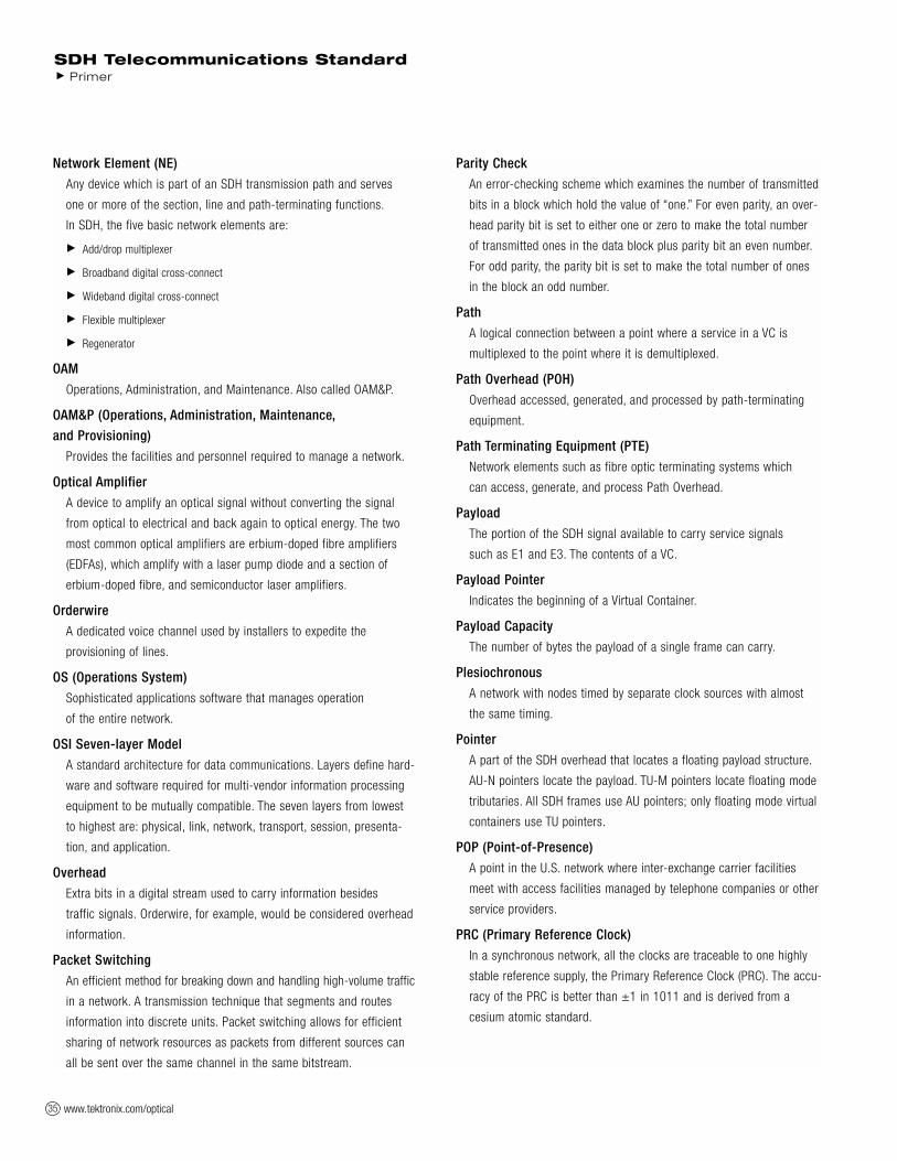
www.tektronix.com/optical35
Network Element (NE)
Any device which is part of an SDH transmission path and serves
one or more of the section, line and path-terminating functions.
In SDH, the five basic network elements are:
Add/drop multiplexer
Broadband digital cross-connect
Wideband digital cross-connect
Flexible multiplexer
Regenerator
OAM
Operations, Administration, and Maintenance. Also called OAM&P.
OAM&P (Operations, Administration, Maintenance,
and Provisioning)
Provides the facilities and personnel required to manage a network.
Optical Amplifier
A device to amplify an optical signal without converting the signal
from optical to electrical and back again to optical energy. The two
most common optical amplifiers are erbium-doped fibre amplifiers
(EDFAs), which amplify with a laser pump diode and a section of
erbium-doped fibre, and semiconductor laser amplifiers.
Orderwire
A dedicated voice channel used by installers to expedite the
provisioning of lines.
OS (Operations System)
Sophisticated applications software that manages operation
of the entire network.
OSI Seven-layer Model
A standard architecture for data communications. Layers define hard-
ware and software required for multi-vendor information processing
equipment to be mutually compatible. The seven layers from lowest
to highest are: physical, link, network, transport, session, presenta-
tion, and application.
Overhead
Extra bits in a digital stream used to carry information besides
traffic signals. Orderwire, for example, would be considered overhead
information.
Packet Switching
An efficient method for breaking down and handling high-volume traffic
in a network. A transmission technique that segments and routes
information into discrete units. Packet switching allows for efficient
sharing of network resources as packets from different sources can
all be sent over the same channel in the same bitstream.
Parity Check
An error-checking scheme which examines the number of transmitted
bits in a block which hold the value of “one.” For even parity, an over-
head parity bit is set to either one or zero to make the total number
of transmitted ones in the data block plus parity bit an even number.
For odd parity, the parity bit is set to make the total number of ones
in the block an odd number.
Path
A logical connection between a point where a service in a VC is
multiplexed to the point where it is demultiplexed.
Path Overhead (POH)
Overhead accessed, generated, and processed by path-terminating
equipment.
Path Terminating Equipment (PTE)
Network elements such as fibre optic terminating systems which
can access, generate, and process Path Overhead.
Payload
The portion of the SDH signal available to carry service signals
such as E1 and E3. The contents of a VC.
Payload Pointer
Indicates the beginning of a Virtual Container.
Payload Capacity
The number of bytes the payload of a single frame can carry.
Plesiochronous
A network with nodes timed by separate clock sources with almost
the same timing.
Pointer
A part of the SDH overhead that locates a floating payload structure.
AU-N pointers locate the payload. TU-M pointers locate floating mode
tributaries. All SDH frames use AU pointers; only floating mode virtual
containers use TU pointers.
POP (Point-of-Presence)
A point in the U.S. network where inter-exchange carrier facilities
meet with access facilities managed by telephone companies or other
service providers.
PRC (Primary Reference Clock)
In a synchronous network, all the clocks are traceable to one highly
stable reference supply, the Primary Reference Clock (PRC). The accu-
racy of the PRC is better than ±1 in 1011 and is derived from a
cesium atomic standard.
SDH Telecommunications Standard Primer

www.tektronix.com/optical 36
Remote Alarm Indication (RAI)
A code sent upstream on an En circuit as a notification that a failure
condition has been declared downstream. (RAI signals were previously
referred to as Yellow signals.)
Remote Defect Indication (RDI)
A signal returned to the transmitting Terminating Equipment when the
receiving Terminating Equipment detects a Loss of Signal, Loss of
Frame, or AIS defect. RDI was previously known as Far End Receive
Failure (FERF).
Remote Error Indication (REI)
An indication returned to a transmitting node (source) that an errored
block has been detected at the receiving node (sink). REI was previ-
ously known as Far End Block Error (FEBE).
Remote Failure Indication (RFI)
A failure is a defect that persists beyond the maximum time allocated
to the transmission system protection mechanisms. When this situa-
tion occurs, an RFI is sent to the far end and will initiate a protection
switch if this function has been enabled.
Regenerator
Device that restores a degraded digital signal for continued transmis-
sion; also called a repeater.
SDH (Synchronous Digital Hierarchy)
The ITU-defined international networking standard whose base
transmission level is 155 Mbit/s (STM-1). SDH standards were first
published in 1989 to address interworking between the ITU and ANSI
transmission hierarchies.
SEC (Synchronous Equipment Clock)
G.813 slave clock contained within an SDH network element.
Section
The span between two SDH network elements capable of accessing,
generating, and processing only SDH Section overhead.
Section Overhead
Nine columns of SDH overhead accessed, generated, and processed
by section terminating equipment. This overhead supports functions
such as framing the signal and performance monitoring.
Section Terminating Equipment (STE)
Equipment that terminates the SDH Section layer. STE interprets
and modifies or creates the Section Overhead.
Slip
An overflow (deletion) or underflow (repetition) of one frame
of a signal in a receiving buffer.
SONET (Synchronous Optical Network)
A standard for optical transport in the United States, Canada, Korea,
and Hong Kong that defines optical carrier levels and their electrically
equivalent synchronous transport signals. SONET allows for a multi-
vendor environment and positions the network for transport of new
services, synchronous networking, and enhanced OAM&P.
SSM (Synchronisation Status Message)
Bits 5 to 8 of SDH overhead byte S1 are allocated for Synchronisation
Status Messages. For further details on the assignment of bit patterns
for byte S1, see the section of this primer on Multiplex Section Overhead.
Stuffing
See bit-stuffing.
Synchronous
A network where transmission system payloads are synchronised
to a master (network) clock and traceable to a reference clock.
A network where all clocks have the same long term accuracy under
normal operating conditions.
Synchronisation Supply Unit (SSU)
A G.812 network equipment clock.
Synchronous Transport Module (STM)
A structure in the SDH transmission hierarchy. STM-1 is SDH’s
base-level transmission rate equal to 155.52 Mbit/s. Higher rates
of STM-4, STM-16, and STM-64 are also defined.
Tributary Unit (TU)
A Tributary Unit is an information structure which provides adaptation
between the Lower-Order path layer and the Higher-Order path layer.
It contains the Virtual Container (VC) plus a tributary unit pointer.
Tributary Unit Group (TUG)
Contains several Tributary Units.
Virtual Container (VC)
A signal designed for transport and switching of sub-SDH payloads.
Wander
The long-term variations of the significant instants of a digital signal
from their ideal position in time (where long term implies that these
variations are of frequency less than 10 Hz).
Wavelength Division Multiplexing (WDM)
WDM is a means of increasing the capacity of fibre-optic data trans-
mission systems through the multiplexing of multiple wavelengths of
light. WDM systems support the multiplexing of as many as four
wavelengths.
Yellow Signal
See Remote Alarm Indication (RAI).
SDH Telecommunications StandardPrimer
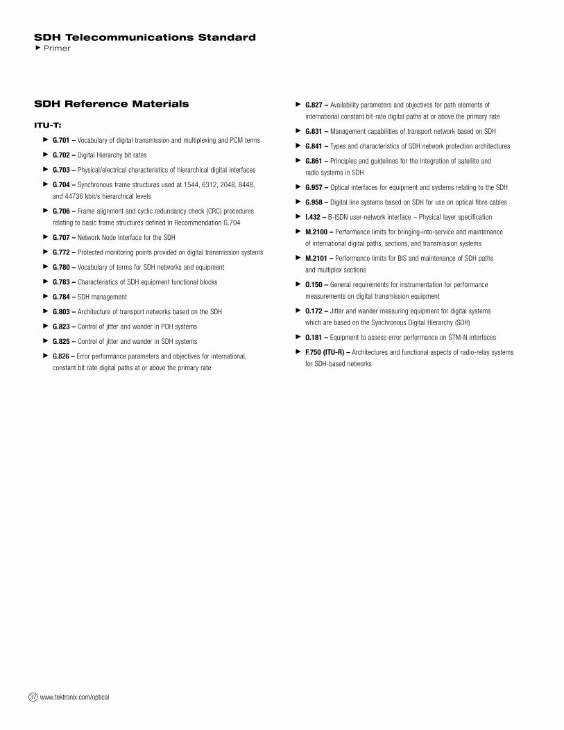
www.tektronix.com/optical37
SDH Reference Materials
ITU-T:
G.701 – Vocabulary of digital transmission and multiplexing and PCM terms
G.702 – Digital Hierarchy bit rates
G.703 – Physical/electrical characteristics of hierarchical digital interfaces
G.704 – Synchronous frame structures used at 1544, 6312, 2048, 8448,
and 44736 kbit/s hierarchical levels
G.706 – Frame alignment and cyclic redundancy check (CRC) procedures
relating to basic frame structures defined in Recommendation G.704
G.707 – Network Node Interface for the SDH
G.772 – Protected monitoring points provided on digital transmission systems
G.780 – Vocabulary of terms for SDH networks and equipment
G.783 – Characteristics of SDH equipment functional blocks
G.784 – SDH management
G.803 – Architecture of transport networks based on the SDH
G.823 – Control of jitter and wander in PDH systems
G.825 – Control of jitter and wander in SDH systems
G.826 – Error performance parameters and objectives for international,
constant bit rate digital paths at or above the primary rate
G.827 – Availability parameters and objectives for path elements of
international constant bit-rate digital paths at or above the primary rate
G.831 – Management capabilities of transport network based on SDH
G.841 – Types and characteristics of SDH network protection architectures
G.861 – Principles and guidelines for the integration of satellite and
radio systems in SDH
G.957 – Optical interfaces for equipment and systems relating to the SDH
G.958 – Digital line systems based on SDH for use on optical fibre cables
I.432 – B-ISDN user-network interface – Physical layer specification
M.2100 – Performance limits for bringing-into-service and maintenance
of international digital paths, sections, and transmission systems
M.2101 – Performance limits for BIS and maintenance of SDH paths
and multiplex sections
O.150 – General requirements for instrumentation for performance
measurements on digital transmission equipment
O.172 – Jitter and wander measuring equipment for digital systems
which are based on the Synchronous Digital Hierarchy (SDH)
O.181 – Equipment to assess error performance on STM-N interfaces
F.750 (ITU-R) – Architectures and functional aspects of radio-relay systems
for SDH-based networks
SDH Telecommunications Standard Primer

www.tektronix.com/optical 38
Notes:
SDH Telecommunications StandardPrimer

Contact Tektronix
ASEAN Countries (65) 356-3900
Australia & New Zealand 61 (2) 9888-0100
Austria, Central Eastern Europe, Greece,
Turkey, Malta & Cyprus +43 2236 8092 0
Belgium +32 (2) 715 89 70
Brazil and South America 55 (11) 3741-8360
Canada 1 (800) 661-5625
Denmark +45 (44) 850 700
Finland +358 (9) 4783 400
France & North Africa +33 1 69 86 81 81
Germany +49 (221) 94 77 400
Hong Kong (852) 2585-6688
India (91) 80-2275577
Italy +39 (02) 25086 501
Japan (Sony/Tektronix Corporation) 81 (3) 3448-3111
Mexico, Central America & Caribbean 52 (5) 666-6333
The Netherlands +31 23 56 95555
Norway +47 22 07 07 00
People’s Republic of China 86 (10) 6235 1230
Poland (48) 22 521 5340
Republic of Korea 82 (2) 528-5299
South Africa (27 11) 254-8360
Spain & Portugal +34 91 372 6000
Sweden +46 8 477 65 00
Switzerland +41 (41) 729 36 40
Taiwan 886 (2) 2722-9622
United Kingdom & Eire +44 (0)1344 392000
USA 1 (800) 426-2200
For other areas, contact: Tektronix, Inc. at 1 (503) 627-1924
Copyright © 2001, Tektronix, Inc. All rights reserved. Tektronixproducts are covered by U.S. and foreign patents, issued andpending. Information in this publication supersedes that in allpreviously published material. Specification and price changeprivileges reserved. TEKTRONIX and TEK are registered trade-marks of Tektronix, Inc. All other trade names referenced are the service marks, trademarks or registered trademarks of theirrespective companies. 8/01 XBS/HMH 2RX-11694-2
Recommended