Embed Size (px)
Citation preview

U s e r M a n u a l
pp
S T 2 4 0 0 A2 . 4 G b / s S D H T e s t S e t
071-0241-04
This document supports firmware version 5.4 and above.

ii ST2400A SDH Test Set User Manual
Copyright © 1999 Tektronix, Inc. All rights reserved. Licensed software products are owned byTektronix or its suppliers and are protected by United States copyright laws and internationaltreaty provisions.
Use, duplication, or disclosure by the Government is subject to restrictions as set forth insubparagraph (c)(1)(ii) of the Rights in Technical Data and Computer Software clause at DFARS252.227-7013, or subparagraphs (c)(1) and (2) of the Commercial Computer Software -Restricted Rights clause at FAR 52.227-19, as applicable.
Tektronix products are covered by U.S. and foreign patents, issued and pending. Information inthis publication supersedes that in all previously published material. Specifications and pricechange privileges reserved.
Tektronix, Inc., P.O. Box 1000, Wilsonville, OR 97070-1000
TEKTRONIX and TEK are registered trademarks of Tektronix, Inc.

ST2400A SDH Test Set User Manual iii
WARRANTY
Tektronix warrants that this product will be free from defects in materials and workmanship for aperiod of three (3) years from the date of shipment. If any such product proves defective duringthis warranty period, Tektronix, at its option, either will repair the defective product without chargefor parts and labor, or will provide a replacement in exchange for the defective product.
In order to obtain service under this warranty, Customer must notify Tektronix of the defectbefore the expiration of the warranty period and make suitable arrangements for the performanceof service. Customer shall be responsible for packaging and shipping the defective product to theservice center designated by Tektronix, with shipping charges prepaid. Tektronix shall pay for thereturn of the product to Customer if the shipment is to a location within the country in whichTektronix service center is located. Customer shall be responsible for paying all shipping charges,duties, taxes, and any other charges for products returned to any other locations.
This warranty shall not apply to any defect, failure or damage caused by improper use or improperor inadequate maintenance and care. Tektronix shall not be obligated to furnish service underwarranty a) to repair damage resulting from attempts by personnel other than Tektronixrepresentatives to install, repair or service the product; b) to repair damage resulting fromimproper user or connection to incompatible equipment; or c) to service a product that has beenmodified or integrated with other products when the effect of such modification or integrationincreases the time or difficulty of servicing the product.
THIS WARRANTY IS GIVEN BY TEKTRONIX WITH RESPECT TO THIS PRODUCT INLIEU OF ANY OTHER WARRANTIES, EXPRESSED OR IMPLIED. TEKTRONIX ANDITS VENDORS DISCLAIM ANY IMPLIED WARRANTIES OF MERCHANTABILITY ORFITNESS FOR A PARTICULAR PURPOSE. TEKTRONIX’ RESPONSIBILITY TOREPAIR OR REPLACE DEFECTIVE PRODUCTS IS THE SOLE AND EXCLUSIVEREMEDY PROVIDED TO THE CUSTOMER FOR BREACH OF THIS WARRANTY.TEKTRONIX AND ITS VENDORS WILL NOT BE LIABLE FOR ANY INDIRECT,SPECIAL, INCIDENTAL, OR CONSEQUENTIAL DAMAGES IRRESPECTIVE OFWHETHER TEKTRONIX OR THE VENDOR HAS ADVANCE NOTICE OF THEPOSSIBILITY OF SUCH DAMAGES.

iv ST2400A SDH Test Set User Manual
How to Reach Customer Service
Tektronix provides high quality Technical Support on applications, operation, measurementspecifications, hardware, and software by expert application engineers. If you have anyquestions regarding the operation, maintenance, repair, or application of your Tektronixequipment, contact your local sales and service office.
For more information on Tektronix equipment and support services, refer to the Tektronixweb-site at www.tektronix.com or call 1-800-Tek-Wide.
ST2400A SDH Test Set User Manual v
Table Of ContentsGeneral Safety Summary .......................................................................................................... ixPreface......................................................................................................................................... xii
Getting StartedProduct Description .................................................................................................................. 1-1Ordering Information................................................................................................................. 1-2
Overview, SDH................................................................................................................................ 1-3Features and Capabilities ......................................................................................................... 1-4Bellcore CLEI and CPR Product Codes .................................................................................. 1-5Accessories ................................................................................................................................ 1-6Standard ...................................................................................................................................... 1-6Optional....................................................................................................................................... 1-6
First-Time Operation.................................................................................................................... 1-8
Functional Overview
Front Panel Controls, Indicators and Connectors ................................................................... 2-1Display, Display Controls and Indicators.............................................................................. 2-2Setup Menu System.................................................................................................................. 2-2Examples of SDH Setup Main Menus .................................................................................... 2-3
Transmitter Description .............................................................................................................. 2-4Transmitter Connectors ............................................................................................................ 2-4Transmitter Status Indicators .................................................................................................. 2-5Mode Key................................................................................................................................... 2-5Tributary and Input Select Keys, Transmitter....................................................................... 2-5OVHD Key, Transmitter............................................................................................................ 2-6Alarm Key, Transmitter............................................................................................................. 2-6Error Key, Transmitter............................................................................................................... 2-6
Receiver Description..................................................................................................................... 2-7Receiver Connectors ................................................................................................................. 2-7Receiver Status Indicators ....................................................................................................... 2-8View History Key....................................................................................................................... 2-9Drop Select Key. Receiver........................................................................................................ 2-9Tributary Select Key, Receiver................................................................................................ 2-9OVHD Key, Receiver................................................................................................................. 2-9
Measurement Controls & Indicators ......................................................................................... 2-10
Front Panel Connections .............................................................................................................. 2-11
Remote Indicators .......................................................................................................................... 2-12
Rear Panel Description ................................................................................................................ 2-12Laser Lockout, Remote Interlock............................................................................................. 2-13SYNC Output.............................................................................................................................. 2-13BITS Ext Ref................................................................................................................................ 2-13Rear Panel Connectors.............................................................................................................. 2-14
Applications and Use..................................................................................................................... 2-15Passive Monitoring................................................................................................................... 2-15Active Analysis ......................................................................................................................... 2-16Active Through Mode Analysis ............................................................................................. 2-17

Table of Contents
vi ST2400A SDH Test Set User Manual
Example - STM-16c/ OC-48c Application............................................................................... 2-17
Reference
Setup Menus ................................................................................................................................... 3-1Laser Menus............................................................................................................................... 3-4Laser Modules ........................................................................................................................... 3-5TX Event Trigger Output Menu.............................................................................................. 3-6View Angle Menu...................................................................................................................... 3-7Store/Recall Setup Menu.......................................................................................................... 3-7Report/ Test Time Menu .......................................................................................................... 3-7Auxiliary Setup Menu............................................................................................................... 3-8Power Fail Recovery.................................................................................................................. 3-9
General Menus & Displays.......................................................................................................... 3-10Menu & Measurement Refinements....................................................................................... 3-10Transmitter or Receiver Configurations................................................................................. 3-12Error Log Display....................................................................................................................... 3-13
Transmitter Menus & Displays .................................................................................................. 3-14TX Source Mode ....................................................................................................................... 3-14External Clock Synchronization............................................................................................... 3-16PRBS Mapping........................................................................................................................... 3-17Input Select, Transmitter.......................................................................................................... 3-18Tributary Select, Transmitter................................................................................................... 3-18Illegal Mode................................................................................................................................ 3-19
Alarm Generation Menus - SDH................................................................................................. 3-20
Overhead Menus (SDH), Transmitter........................................................................................ 3-22Ability to Edit Multi-byte J0 Trace ......................................................................................... 3-23J0, J1 Trace Capture & Display................................................................................................ 3-26Ability to Edit M1 Byte............................................................................................................. 3-28
Error Generation Menus (SDH).................................................................................................. 3-29B2 or B3 Error Inject ................................................................................................................. 3-31Inject Random BER on one Selectable Channel ................................................................... 3-32
Receiver Menus & Displays ........................................................................................................ 3-33Error Measurements, Receiver................................................................................................. 3-33Error Measurement Details ....................................................................................................... 3-40G.826 and M.2101 Measurements in SDH Mode.................................................................. 3-40Overhead Displays, Receiver................................................................................................... 3-42ASCII Synchronization Messages - S1 byte......................................................................... 3-43Automatic Protection Switching (APS).................................................................................. 3-44Receiver Tributary Select ......................................................................................................... 3-45Receiver Tributary - RX Channel Selection (SDH)............................................................... 3-46Pointers Information from Receiver Tributary Key (SDH) .................................................. 3-46Receiver Drop Select................................................................................................................. 3-47
AppendicesSpecifications, SDH....................................................................................................................... A-1
Incoming Inspection Test............................................................................................................. B-1
Factory Defaults ............................................................................................................................. C-1
SONET for Reference................................................................................................................... F-1
SDH Glossary and ITU-T Standards ........................................................................................... G-1

ST2400A SDH Test Set User Manual vii
Index................................................................................................................................................. I-1

Preface
ST2400A SDH Test Set User Manual viii
General Safety SummaryReview the following safety precautions to avoid injury and prevent damage to this product or anyequipment connected to it. To avoid potential hazards, use this product only as specified.
To avoid potential hazards, use this product only as specified.
Only qualified personnel should perform service procedures.
While using this product, you may need to access other parts of the system. Read the GeneralSafety Summary in other system manuals for warnings and cautions related to operating thesystem.
Injury Precautions
Use Proper Power Cord
To avoid fire hazard, use only the power cord specified for this product.
Avoid Electric Overload
To avoid electric shock or fire hazard, do not apply a voltage to a terminal that is outside the rangespecified for that terminal.
Ground the product
This product is grounded through the grounding conductor of the power cord. To avoid electricshock, the grounding conductor must be connected to earth ground. Before making connections tothe input or output terminals of the product, ensure that the product is properly grounded.
Do not operate without covers
To avoid electric shock or fire hazard, do not operate this product with covers or panels removed.
Use Proper Fuse
To avoid fire hazard, use only the fuse type and rating specified for this product.
Do not operate in Wet/Damp Conditions
To avoid electric shock, do not operate this product in wet or damp conditions.

General Safety Summary
ST2400A SDH Test Set User Manual ix
Do not operate in Explosive Atmosphere
To avoid injury or fire hazard, do not operate this product in an explosive atmosphere.
Wear Eye Protection
To avoid eye injury, wear eye protections if there is a possibility of exposure to high-intensity rays.
Product Damage Precautions
CAUTION!Signal levels greater than –10dBm (negative 10dBm) may damage the Optical Input devices.Always pad the input level to less than –10dBm.
Always use 15 dB of attenuation when connecting the ST2400A Transmitter output to its receiverinput. Failure to do so will damage the optical detector.
Use Proper Power Source
Do not operate this product from a power source that applies more than the voltage specified.
Provide Proper Ventilation
To prevent product overheating, provide proper ventilation.
Do not operate with suspected failures
If you suspect there is damage to this product, have it inspected by qualified service personnel.

General Safety Summary
x ST2400A SDH Test Set User Manual
Safety Terms and Symbols
Terms in this manual
These terms may appear in this manual:
Icon Label Meaning
W A R N I N G !W A R N I N G ! Warning statements identify conditions or practices that could result ininjury or loss of life.
C A U T I O N !C A U T I O N ! Caution statements identify conditions or practices that could result indamage to this produce or other property.
DANGER indicates an injury hazard immediately accessible as you read the marking.
WARNING indicates an injury hazard not immediately accessible as you read the marking.
CAUTION indicates a hazard to property including the product.
Symbols on the Product
The following symbols may appear on the product:
DANGERHigh Voltage
Protective Ground(Earth) Terminal
ATTENTIONRefer to Manual
Double Insulated
Certifications and Compliance
CSA Certified Power Cords
CSA Certification includes the products and power cords appropriate for use in the NorthAmerican power network. All other power cords supplied are approved for the country of use.

Preface
ST2400A SDH Test Set User Manual xi
PrefaceThis manual describes how to use the Tektronix ST2400A SDH Test Set. This manual is yourprimary source of information about how the ST2400A SDH Test Set functions.
How This Manual is Organized
This manual is divided into four sections: Getting Started, Operating Basics, Reference, andAppendices.
• Getting Started provides an overview of the ST2400A SDH Test Set and describes first-timeoperation.
• Operating Basics explains the basic principles of operating the ST2400A. The OperatingBasics section also includes sample ST2400A applications.
• Reference provides explanations of how to perform detailed tasks.
• The Appendices provide a listing of specifications, default factory setting, an incominginspection test, and other useful information.
Conventions
This manual uses the following conventions:
• The names of front-panel controls and menus appear in all upper case letter, for example,TRANSMIT and HELP.
• Names appear in the same case in this manual as they appear on the display of the ST2400A,for example, Test Duration and USER DEFINED.
• Within a procedure, a specific button to be pressed or a parameter to be selected appears inboldface print.
NOTE! Some of the content found in this manual does not pertain to some instruments.Depending on the software revision and the options installed, some of the featuresdescribed in these pages may not be available.
Related Manuals
The following documents are available for the ST2400A SDH Test Set:
• ST2400A SDH/SONET Programmer Manual (Tektronix part number 071-0243-xx)describes how to control the ST2400A using an instrument controller.
• ST2400A SONET/SDH Test Set Service Manual (Tektronix part number 071-0244-xx)provides information on maintaining and servicing your instrument to the module level.

General Safety Summary
xii ST2400A SDH Test Set User Manual

Getting Started


ST2400A SDH Test Set User Manual 1-1
Getting StartedThis chapter describes the ST2400A 2.4 Gb/s SDH/SONET Test Set and provides a list ofstandard and optional accessories for both the SDH and SONET option and for each of the threeconfigurations: TRANSCEIVER, TRANSMITTER, and RECEIVER.
Unique front panel "Transceiver", "Transmitter", and "Receiver" labels will be affixed to the topright corner of ST2400A, depending on configuration.
Product Description
TRIB OVHD
ERROR
155/2.048 CLK IN
75 OHM
ST2400A 2.4 Gb/s SDH/SONET Test Set
GPIBLLO REM
INC ENTER RUN/STOP
DEC SETUP PAUSE/RESUME
LOS B1 AIS
LOF B2 RDI/FERF
OOF REI/FEBE
AVOID EXPOSURE TO BEAMINVISIBLE LASER RADIATIONIS EMITTED FROM APERTURECLASS 3B LASER PRODUCT21 CFR 1040.10 APR 97
OVHD MODE TRIB
ALARM ERROR
-10dBm MAX 0dBm NOM -10dBm MAX -8dBm MAX
155/ 622 INPUT STATUS LOS LOF
INPUTSELECT
155
622
155
155
622
2.4 Gb/s STATUS
DROP SELECT VIEW HISTORY
155 OUT
75 OHM
2.4 Gb/s IN 155/ 622 OUT LASER ON
155 / 622 IN 2.4 GB/s OUT LASER ON
1310 1550 1310/1550 1310
!!
|
0
Figure 1-1. Example of ST2400A 2.4 Gb/s SDH/SONET Test Set Front Panel
The ST2400A 2.4 Gb/s SDH/SONET Test Set provides Multiplexer Section and RegeneratorSection signal generation and analysis for the 2.4 Gb/s SDH STM-16 or SONET OC-48standards. The ST2400A is a versatile unit that can be ordered in one of three configurations:Transceiver, Transmitter, or Receiver. The front panel design (Figure 1–1) is the same for boththe SDH and SONET functions.
The lasers in the ST2400A are Class IIIA per IEC 825-1 for SDH and Class IIIB per 21 CFR1040 for SONET.

Getting Started
1-2 ST2400A SDH Test Set User Manual
Ordering InformationOptions DescriptionST2400A STM-16/OC-48 SDH/SONET TransceiverIncludes: 2.488 Gbit/s Transmitter and Receiver with electrical clock and data, tributary add/drop, powercord, user manual
13 Add wideband receive optics and 1310 nm IR 2.488 Gbit/s laser15 Add wideband receive optics and 1550 nm IR 2.488 Gbit/s laser17 Add wideband receive optics and switchable 1310 nm IR laser and 1550 nm long-reach
2.488 Gbit/s laser35 Add wideband receive optics and switchable 1310 nm IR laser and 1550 nm long-reach
2.488 Gbit/s laser41 STM-16c/ OC-48c payloads42 Add B3 Path Analysis
ST2400R STM-16/OC-48 SDH/SONET ReceiverIncludes: 2.488 Gbit/s Receiver with electrical clock and data, tributary drop, power cord, user manual
11 Receive only with 2.4 Gbit/s wideband optics
42 Add B3 Path AnalysisST2400T STM-16/OC-48 SDH/SONET TransmitterIncludes: 2.488 Gbit/s Transmitter with electrical clock and data, tributary add, power cord, user manual
13 Add 1310 nm intermediate-reach 2.488 Gbit/s laser15 Add 1550 nm long-reach 2.488 Gbit/s laser17 Add switchable 1310 nm IR laser and 1550 nm long-reach 2.488 Gbit/s laser35 Add switchable 1310 nm IR laser and G.692 specific frequency long-reach
2.488 Gbit/s laser41 STM-16c/ OC-48c payloads42 Add B3 Path Analysis
ST2400A, ST2400R, and ST2400T Common Options01 FC/PC optical connectors (Option 01, 02, or 03 must be chosen)02 SC/PC optical connectors (Option 01, 02, or 03 must be chosen)03 ST/PC optical connectors (Option 01, 02, or 03 must be chosen)05 Rack mount06 FC/PC 15 dB attenuator for 2.488 Gbit/s receiver07 SC/PC 15 dB attenuator08 ST/PC 15 dB attenuatorC3 Three year calibration serviceC5 Five year calibration serviceD3 Three year calibration data reportD5 Five year calibration data reportR5 Extended warranty to five years

Getting Started
ST2400A SDH Test Set User Manual 1-3
Overview, SDH
The ST2400A Transceiver version can transmit and receive STM-16 signals. The ST2400A hasthe ability to receive, generate and modify an STM-16c signal. The transmitter section caninternally generate a 2.4 Gb/s signal or multiplex the higher-rate signal from STM-1 or STM-4signal inputs. The ST2400A can also accept a STM-16 signal in through mode and regenerate it.The receiver section receives an STM-16 signal, demultiplexes it, and can drop out either theSTM-1 or STM-4 signal as required.
The Transmitter version can generate and transmit the STM-16 signal from an internal source, ormultiplex the higher-rate signal from either STM-1 or STM-4 signal inputs. In the case ofSTM-4c and STM-16c, the ST2400A can either generate four STM-4c tributary signals withPRBS payloads inside an STM-16 envelope, or generate three tributary payloads of PRBSSTM-4c and insert a fourth from outside the tributary interface (which could contain IP traffic). Inthe case of STM-16c, the entire (single) payload is PRBS. All applicable SDH Path Pointer Bytes(H1/H2/H3) are set correctly to indicate the type of payload being carried (STM-4c/STM-16c, etc.).
The Receiver version can receive and demultiplex the STM-16 signal and drop either the STM-1or STM-4 signal to an auxiliary test set, as required.
The ST2400A can accept zero, one or two factory-installed 2.488 Gb/s laser transmitter modules.It can also accept zero or one APD receiver module (also referred to as I/O modules). One typeof laser transmitter – direct modulated (DM) – is available.
The ST2400A provides electrical input and output clock and data interfaces operating at 2.488Gb/s. Base Transceiver configuration provides 2.488 Gb/s electrical interfaces and 155/622 Mb/soptical and electrical add/drop tributary interfaces. Transmitter configurations do not include155/622 optical and electrical drop interface. Receiver configurations do not include 155/622optical and electrical add interface.
The user can individually enable and disable laser #1 (if installed), laser #2 (if installed), andelectrical outputs. Multiple outputs can be simultaneously active.
NOTE: RX will not measure correctly if both TX lasers are enabled and looped back to RX(since RX contains a single broadband optical detector, which is not wavelength-selective).
The ST2400A 2.4 Gb/s SDH/SONET Test Set is designed to integrate directly with otherTransmission Analyzers, such as the Tektronix CTS 750 or the Tektronix CTS 850. The ST2400Aunit can operate with many other STM-1 and STM-4 test sets that accept 155 or 622 Mb/s opticalsignals and the 155 Mb/s CMI electrical signal.

Getting Started
1-4 ST2400A SDH Test Set User Manual
ST2400A 2.4 Gb/s SDH/SONET Test Set Features and Capabilities:
• STM-16 SDH RS and MS Testing B1, B2, B3 Error Generation B1, B2, B3 Error Measurement Path REI, Path Alarms, Pattern Bit Error J0, J1 Capture; J0 Edit RS and MS Alarm Generation RS and MS Alarm Detection RS and MS Layer Alarm and Error Generation
• VC4 PRBS Mappings
• Ability to receive, generate and modify a STM-16c Payload (Option 41)
• External Clock Input (2 Mbps/ 2 Mhz) or 1.5 Mbps
• User-selectable power failure recovery mode
• Electrical Offset of Receiver Decision Threshold
• +/- 1 nm wavelength tuning
• CW laser source mode
• 2.488 Gb/s electrical I/O
• 3-year warranty
• Automatic Optical Receiver shut-off if power exceeds maximum rating
• Specific wavelengths G.692 lasers available in 1550 nm region
• Portable—11.4 kilograms (25 pounds) maximum weight
• A simple menu system
• Tributary Access at 155 Mb/s or 622 Mb/s
• Easily software switched between SDH and SONET modes
• Integrates with the CTS 750 or CTS 850 for complete “all-rate” SDH analysis
• Wide optical range: 3 dBm to -2 dBm Typical Output Power–28 dBm to –10 dBm Receiver Sensitivity
• Through Mode with Overhead Editing, Error, and Alarm Injection
• Direct user download of software updates

Getting Started
ST2400A SDH Test Set User Manual 1-5
• CCITT/ITU G.708, G.709 and GR-253-CORE framing

Getting Started
1-6 ST2400A SDH Test Set User Manual
• Complete Remote ControlRS-232 and GPIB ports, and standard printer interfacesLabView, LabWindows CVI, and HP VeeLAN (using LAN to GPIB converters)ST2400A GUI Front Panel Utility
• Standard tributary interfaces
STM-1e 155 Mb/s electricalSTM-1 155 Mb/s opticalSTM-4 622 Mb/s optical
• Interface to Regenerator Section Terminating Element and Multiplexer Section TerminatingElement and other test equipment
With firmware version 5.0 (Option 42), the following new features are added to capabilities of theST2400A:
• Payload bit error injection/ B3 Injection on the TX side (TSE)
• B3, Path-REI, Payload bit error count measurement on the RX side (TSE ES, SES (SDHonly)
• Alarm signal status (RX) - Path RDI, Loss of Pointer, Path AIS, Path REI
• Path Overhead Monitor (RX) - Displays value of following bytes: J1, B3, C2, G1, F2, H4,Z3/F3, Z4, N1
• For the path overhead, C2 byte added at TX (Path Signal Label C2)) - Identifies High OrderPath Label Unequipped and High Order Path Label Mismatch. C2 byte can be set to anyvalue from 0x00 to 0xFF.
• B3 Path Analysis/ J1 Path Trace (displayed as ASCII text).
• Tx Patterns. PRBS 2-31-1 and 2-31-1 Inverted; Fixed (00 to FF) (TX mode button)
• Pointers (Read-only menu under RX Trib button). Pointer Value displayed (0 to 782). PointerMeasurement Counts for Positive Pointer Justifications, Negative Pointer Justifications, NewData Flag (NDF)
• Extended capability of View History button (more LEDs - virtual LEDs)
• APS Switch Time measurement (LOF, LOS durations). APS testing can be performed bycausing protection switch via control of K1/K2 bytes and then displaying time to restore framesynchronization. Highly-accurate LOF timer enables this test to be performed with<1 ms resolution.
• RX mapping (PRBS 2-23-1 and 2-23-1 Inverted; PRBS 2-31-1 per ITU-T O.151 and 2-31-1
Inverted per ITU-T O.181, User-defined byte 0x00 to 0xFF) (RX Channel Selection, underRX Trib button)
NOTE: Option 42 must be purchased for B3 capabilities (To determine if a TX board is B3capable, the return value from the remote command "tx_brd_rev" must be greater than or equal to35. To determine if an RX board is B3 capable, the return value from the remote command"rx_brd_rev" must be greater than or equal to 9).

Getting Started
ST2400A SDH Test Set User Manual 1-7
The ST2400A meets the needs of development, manufacturing, and service engineers by providingthe capabilities for:
• System interrogation and conformance testing
• Manufacturing Production Testing
• Network Integrity testing
• Network Performance monitoring
• Network Troubleshooting
Bellcore CLEI and CPR Product Codes
Bellcore COMMON LANGUAGE Product Codes are available for the ST2400A upon request.
Accessories
Some accessories are included with the ST2400A 2.4 Gb/s SDH/SONET Test Set. If youwish to purchase optional accessory contact your local Tektronix Representative.
Standard
User Manual; Certificate of Traceable Calibration; Front Cover; Power Cord
Optional
Rackmount
Carrying Case
Interface Cables, RS-232-C, GPIB, CentronicsRS-232-C012-1379-00 9-pin female to 9-pin male012-1298-00 9-pin female to 25-pin male012-1398-00 9 in. RS-232-C to plotter/printer
GPIB012-0991-00 2m, double-shielded012-0991-01 1m, double-shielded012-0991-02 4m, double-shielded012-1282-00 0.5 m, GPIB
Centronics012-1233-00 3 m, 4693 to Terminal012-1214-00 8 ft. Male Centronics to PC 25-Pin D012-1284-00 9 ft. male to male

Getting Started
1-8 ST2400A SDH Test Set User Manual
Interface Cables, used for CE Certification1M-BM-SB142-BM BNC to BNC (50 OHM) 1 meter length1M-BM-4233-BM BNC to BNC (75 OHM) 1 meter lengthH1740-1 Printer Cable, 8 feet8004570 DB25 Male to Female, 6 feet8004569 DB9 Male to Female 6 feetCIB24-1M GPIB 1EEE-488 1 meter lengthCIB24X GPIB Adapter
Adapters, SMA015-0369-00 SMA male to N015-0572-00 SMA male to BNC male015-0554-00 SMA male to BNC female015-1009-00 SMA male to N female015-0553-00 Threaded female to male slip-on connector015-0549-00 Male to female connector (Used permanently
installed to prolong life of instrument connector)020-1693-00 SMA Kit
Attenuator, OpticalRecommended:AMP 06-0033 FC Style Build Out Attenuator 15 dB Fixed Valueor equivalent.
Option 1A provides an attenuator.
International Power Plug Options
Option # DescriptionA1 220V, Euro PlugA2 240V, UK PlugA3 240V, Aust PlugA4 240V, North American PlugA5 220V, Swiss Plug

Getting Started
ST2400A SDH Test Set User Manual 1-9
First Time Operation
Unpacking
Unpack the ST2400A 2.4 Gb/s SDH/SONET Test Set and place the unit on a hard firmsurface.
ST2400A Installation
Before using the ST2400A verify that it is properly set up and powered on, as follows:
1. Remove the unit from its shipping carton and place it on a hard firm surface.
2. Verify that the operating environment is within the limits detailed under the EnvironmentalRequirement section in this manual.
3. Allow approximately 2 inches (5 cm) clearance for cooling on the top and rear of the unit. Thetwo rear panel fans draw air into the ST2400A which is exhausted through the top vents.
4. Connect the unit for a chosen application. Never exceed the maximum optical power limits(–10dBm) listed on the front panel. When not using, always cover the optical connectors.
CAUTION!Signal levels greater than –10dBm (negative 10dBm) may damage the Optical Input devices.Always pad the input level to less than –10dBm.
Always use 15 dB of attenuation when connecting the ST2400A Transmitter output to its receiverinput. Failure to do so will damage the optical detector.
1. Verify that the rear panel key lock is in the desired position.
2. Plug the unit into the appropriate AC Power source as follows:
Table 1-1. Power Requirements
AC Voltage Voltage Range Frequency Range Maximum Power110 VAC 90 VAC - 132 VAC 48 - 62 Hz 250 Watts220 VAC 180 VAC - 250 VAC 48 - 62 Hz 250 Watts
Operating Basics


ST2400A SDH Test Set User Manual 2-1
Functional OverviewThis section describes ST2400A 2.4 Gb/s SDH/SONET Test Set controls, indicators,connectors, display elements, and menu structures. It includes separate sections that detailReceiver and Transmitter specifics, and general sections that apply to both.
Front Panel Controls, Indicators, and Connectors
Figure 2-1 shows a complete view of the front panel.
W A R N I N G !W A R N I N G ! Always avoid exposure to the laser beam. Before power is applied tothe ST2400A 2.4 Gb/s SDH/SONET Test Set, be sure that all laser outputs are either coveredwith the screw cap provided or connected to the appropriate circuit.
The lasers in the ST2400A (SDH) are Class IIIA per IEC 825-1.
TRIB OVHD
ERROR
155/2.048 CLK IN
75 OHM
ST2400A 2.4 Gb/s SDH/SONET Test Set
GPIBLLO REM
INC ENTER RUN/STOP
DEC SETUP PAUSE/RESUME
LOS B1 AIS
LOF B2 RDI/FERF
OOF REI/FEBE
AVOID EXPOSURE TO BEAMINVISIBLE LASER RADIATIONIS EMITTED FROM APERTURECLASS 3B LASER PRODUCT21 CFR 1040.10 APR 97
OVHD MODE TRIB
ALARM ERROR
-10dBm MAX 0dBm NOM -10dBm MAX -8dBm MAX
155/ 622 INPUT STATUS LOS LOF
INPUTSELECT
155
622
155
155
622
2.4 Gb/s STATUS
DROP SELECT VIEW HISTORY
155 OUT
75 OHM
2.4 Gb/s IN 155/ 622 OUT LASER ON
155 / 622 IN 2.4 GB/s OUT LASER ON
1310 1550 1310/1550 1310
!!
|
0
Figure 2-1. Example of ST2400A Front Panel
The front panel can be divided into functional sections:
• Display and Display Controls
• Transmitter Controls and Connectors (Left-side of front panel)
• Receiver Controls and Connectors (Right-side of front panel)

Functional Overview
2-2 ST2400A SDH Test Set User Manual
Display, Display Controls, and Indicators
The figure below shows the ST2400A 2.4 Gb/s SDH/SONET Test Set display and displaycontrols. The display is a two-line by twenty-four character back-lit super twisted Nematic LCD(liquid crystal display) that provides a sharp image and increased viewing angle in all directions.
The LCD display is used to present main menus, submenus, and test results. The right and leftarrows are used to position the LCD cursor. The INC (increment) and DEC (decrement) keysare used to change values. The ENTER key is used to insert the selected value.
The ENTER key houses a red LED indicator that flashes whenever an action is requested orrequired. It will continue to flash until the ENTER key is pressed, entering a new value orexecuting the function.
ST2400A 2.4 Gb/s SDH/SONET Test Set INC ENTER RUN/STOP
DEC SETUP PAUSE/RESUMEAVOID EXPOSURE TO BEAMINVISIBLE LASER RADIATIONIS EMITTED FROM APERTURECLASS 3B LASER PRODUCT21 CFR 1040.10 APR 97
Figure 2-2. ST2400A LCD Display
Setup Menu System
The SETUP key is located below the ENTER key on the front panel. Pressing the SETUP key atany time will start the menu sequence. Each additional press, represented by the black arrow, willaccess the next menu. The number of main menus is mode dependent. Some main menus havesubmenus, omitted in this chapter, but detailed in Chapter 3- Reference. The SETUP menus arearranged in a continuous loop. Press any other key to exit the setup mode.
W A R N I N G ! W A R N I N G !Before activating the 2.4 Gb/s LASER, its output must be connected to a circuit.
CAUTION!Signal levels greater than –10dBm (negative 10dBm) may damage the Optical Input devices.Always attenuate the input level to less than –10dBm.
Always use 15 dB of attenuation when connecting the ST2400A Transmitter output to itsReceiver input. Failure to do so will damage the optical detector.

Functional Overview
ST2400A SDH Test Set User Manual 2-3
Examples of SDH Setup Main Menus (depending on Configuration)
SDH QUICK SETUPINT <155> 622 EXT 155 622
LASER 1 L-16.1 (1310) <OFF> ON CW SETUP
TX EVENT TRIGGER OUTPUT <ALARM> ERROR
STORE/ RECALL SETUP<USER> FACTORY DEFAULT
VIEW ANGLE VOLUME 1 1
AUXILIARY SETUP <ENTER>
REPORT/ TEST TIME <ENTER>
Figure 2-3. Examples of SDH Setup Main Menus
Since the ST2400A can be configured as Transceiver, Transmitter or Receiver, many menus areavailable only with the appropriate configuration.
For example, the Quick Setup menu displayed above is available with the Transceiver, but doesnot appear in the Transmitter or Receiver configurations. The TX Event Trigger Output menu isavailable in the Transceiver or Transmitter configurations. The Report/Test Time menu isavailable in the Transceiver or Receiver configurations.

Functional Overview
2-4 ST2400A SDH Test Set User Manual
Transmitter Description
This section describes the Transmitter inputs, outputs, controls and indicators. The figure belowshows the ST2400A 2.4 Gb/s SDH/SONET Test Set Transmitter front panel area, located onthe left side of the front panel. The Transmitter button choices are not functional on the ST2400Aconfigured as a Receiver.
OVHD MODE TRIB
ALARM ERROR
155 / 622 IN 2.4 GB/s OUT LASER ON
155/2.048 CLK IN
75 OHM
-10dBm MAX 0dBm NOM
155/ 622 INPUT STATUS LOS LOF
INPUTSELECT
155
622
1551310 1550
!
Figure 2-4. Transmitter Front Panel
Transmitter Connectors
There can be three connectors on the Transmitter front panel—one electrical CMI (Code MarkInversion) (155 electrical) and two optical. The CMI electrical carrier connector is an industrystandard BNC that is marked 155/2.048 CLK IN. It provides a 75 ohm load impedance anddirect coupling (DC) for the 155 Mb/s SDH electrical signal.
This connection also accepts 2.048 Mb/s or 2.048 MHz ± 40 PPM SETS input for internal signalgeneration using external timing synchronization. SETS input accepts signals meeting therequirements of G.703 section 10 (2.048 Mb/s) and section 6 (2.048 Mhz), with the exception offrequency tolerance of ± 40 PPM. The user will have the ability to select which of the timingsources (internal or external 2.048 Mb/s or 2.048 MHz) is active. When an external clock sourceis selected, but no clock activity is detected, the user will be alerted to Loss of External Clock.
On the right side of the Transmitter section are two industry standard FC/PC optical connectors—one input and one output. ST and SC connectors are available as an option. The input opticalconnector is marked 155/622 IN; it accepts either STM-1 or STM-4 signals, at 1310nm. Theoutput optical connector is marked 2.4 Gb/s OUT; it outputs an STM-16 signal. Both areequipped with screw caps to protect the optics from airborne contamination, such as dust.
W A R N I N G ! W A R N I N G !Before activating the 2.4 Gb/s LASER its output must be connected to a circuit.
C A U T I O N ! C A U T I O N !Always use 15 dB of attenuation when connecting the ST2400A Transmitter output to itsReceiver input. Failure to do so will damage the optical detector.

Functional Overview
ST2400A SDH Test Set User Manual 2-5
Transmitter Status Indicators
The 155/622 INPUT STATUS section has five LED indicators—three yellow and two red. TheSELECT key is used to choose between the two optical inputs and one electrical. When the inputis external, the yellow LEDs indicate which input has been chosen.
The two red indicators are labeled LOS (Loss Of Signal) and LOF (Loss Of Frame). Theymonitor the 155 and 622 inputs for those alarm conditions. Both LEDs are off when theappropriate incoming signal is present. They are disabled when the unit is internally generating a2.4 Gb/s or is in the through mode (see the Mode Key section).
Mode Key
Pressing the MODE key will access the Transmitter input selection menu. It is used to chooseone of the three data sources that will produce the 2.4 Gb/s output signal and select thewavelength when a dual wavelength Transmitter option is installed. The three choices are: EXT,an external input tributary from the Transmitter front panel; INT, an internally generated 2.4Gb/s signal; and THRU, a through input from the Receiver section.There are also choices forPattern Selection, Mapping Selection, and External Sync Input options under the MODE key.
The EXT input can be 155 Mb/s optical (STM-1), 622 Mb/s optical (STM-4), or 155 Mb/s CMIelectrical signal. The appropriate yellow status LED will indicate the input signal.
The INT mode generates an unequipped SDH 2.4 Gb/s (STM-16) signal with valid transportoverhead bytes that can be modified.
The Transceiver THRU mode will output a modified 2.4 Gb/s SDH signal that entered theReceiver section from an external source before modification. All three yellow status LEDs willbe off when the ST2400A is in the THRU (Through) mode or INT mode.
The Transceiver WAVELENGTH menu will only be present when the dual wavelength option isinstalled. Use the arrow keys to move the cursor to either 1310nm or 1550nm and the enter key toselect the value.
Tributary and Input Select Keys, Transmitter
The Transmitter TRIB key is used with the INPUT SELECT key to configure input groupings.STM-16 has sixteen STM-1 channel groups or four STM-4 channel groups.

Functional Overview
2-6 ST2400A SDH Test Set User Manual
OVHD Key, Transmitter
The Transmitter OVHD (Overhead) key provides access to the Regenerator Section andMultiplexer Section overhead bytes in the first column of the first STM-1. The figure below showsthe menu used to access the E1 byte. A field change occurs when an arrow key is used to movethe cursor from PASS to SET. The field change shows the current value of the particularoverhead byte being viewed. Greater detail is provided in Chapter 3 - Reference.
RS EOW E1<PASS> SET --
RS EOW E1PASS <SET> 7F
Main Menu
Field Change
Figure 2-5. Overhead Menu Access
Alarm Key, Transmitter
The Transmitter alarm key is used to inject any of the alarms in one of four modes: continuous,timed, burst, or repeat at specific intervals. The alarm displays and menus are detailed in the nextchapter. The red LED indicator in the alarm key will be illuminated whenever an alarm is active.
Error Key, Transmitter
The Transmitter error key is used to generate specific error conditions that are detailed inChapter 3 - Reference. The red LED indicator in the error key will be illuminated whenever analarm is active.

Functional Overview
ST2400A SDH Test Set User Manual 2-7
Receiver Description
This section describes the ST2400A 2.4 Gb/s SDH/SONET Test Set Receiver front panelinputs, outputs, controls, and indicators, located on the right side of the front panel. The Receiverbutton choices are not functional on the ST2400A configured as a Transmitter.
TRIB OVHD
ERROR
LOS B1 AIS
LOF B2 RDI/FERF
OOF REI/FEBE
-10dBm MAX -8dBm MAX
155
622
2.4 Gb/s STATUS
DROP SELECT VIEW HISTORY
155 OUT
75 OHM
2.4 Gb/s IN 155/ 622 OUT LASER ON
1310/1550 1310
!
Figure 2-6. Receiver Front Panel
Receiver Connectors
There are three connectors on the Receiver front panel—one electrical CMI (Code MarkInversion) and two optical. The CMI electrical signal connector is an industry standard BNC thatis marked 155 OUT. It provides the 75 ohm load impedance and direct coupling (DC) for theSDH electrical signal.
The two industry standard FC/PC optical connectors are on the left side of the Receiver section,one input and one output. ST or SC connectors are available as options. The input optical connectoris marked 2.4 Gb/s IN, it accepts the STM-16 signal, at either 1310 or 1550 nm. The output opticalconnector, marked 155/622 OUT, outputs STM-1 and STM-4 tributary signals at 1310 nm. Bothare equipped with screw caps to protect the optics from airborne contamination, such as dust.
W A R N I N G ! W A R N I N G !Before activating the 2.4 Gb/s LASER its output must be connected to a circuit.
C A U T I O N ! C A U T I O N !Always use 15 dB of attenuation when connecting the ST2400A Transmitter output to itsReceiver input. Failure to do so will damage the optical detector.

Functional Overview
2-8 ST2400A SDH Test Set User Manual
Receiver Status Indicators
TRIB OVHD
ERROR155 OUT
75 OHM
LOS B1 AIS
LOF B2 RDI/FERF
OOF REI/FEBE
155
622
2.4 Gb/s STATUS
DROP SELECT VIEW HISTORY
Figure 2-7. Receiver Status Indicators
The status indicators include the alarms and errors detailed below. The appropriate LED indicatorwill light for a minimum of 200 milliseconds when a corresponding alarm or error is detected.Detected errors and alarms are stored as historical data.
The Receiver LOS (Loss Of Signal) alarm indicates that the 2.4 Gb/s Input signal has not beendetected for more than 2 microseconds. The LOS alarm will be asserted no later than 127microseconds after receiving the low signal (all zero) condition.
The Receiver LOF (Loss Of Frame) alarm indicates that more than 3 milliseconds of an out offrame condition has occurred.
The OOF (Out Of Frame) alarm indicates that more than 4 consecutive frames of the 2.4 Gb/ssignal had frame alignment errors.
The B1 and B2 LEDs indicate that Regenerator Section or Multiplexer Section (respectively)parity errors were detected.
The REI/FEBE (Remote Error Indication or Far End Block Error) indicates that a non-zero valuein the REI byte (M1 byte in MS-OH) was detected.
The RDI/FERF (Remote Defect Indication or Far End Receive Failure) alarm indicates that bits6, 7, and 8 of the K2 byte have been a binary 110, respectively, for three or more consecutiveframes.
The AIS (Alarm Indication Signal) indicates that bits 6, 7, and 8 of the K2 byte have been a binary111, respectively, for three or more consecutive frames.
The 155 and 622 LEDs function in conjunction with the DROP SELECT key to indicate whichoptical drop rate has been selected. Both LEDs are off when the 155 Mb/s electrical drop isselected.

Functional Overview
ST2400A SDH Test Set User Manual 2-9
View History Key
The VIEW HISTORY key reviews past alarms and errors. A history status bit is set, and thestatus LED built into the key flashes whenever an alarm or error is detected during the run mode.Pressing this key will display the history status of the alarm and error LED indicators instead ofthe current status. Releasing this key will return to the current status display within 200milliseconds. History is cleared when a new test cycle starts.
The VIEW HISTORY key also permits the display of additional LED indicators.
Any error or alarm on PATH will cause the VIEW HISTORY light to blink.
There are three status indicators in the menu below. The "-" indicates a cleared condition (noerrors of this type have been detected since the test began). The "*" indicates a present errorcondition (an error of this type is now occurring). The "h" indicates a history condition (an error ofthis type occurred at some point during the test, but is not occurring at this time).
B3 h PL-BIT * P-REI --
LOP - P-AIS h P-RDI --
Figure 2-8. VIEW HISTORY additional LED indicators (SDH)
Drop Select Key, Receiver
The DROP SELECT key is used to select one of three drops from the 2.4 Gb/s (STM-16) signal.The 155 Mb/s signal (STM-1) can be either electrical or optical. The 622 Mb/s (STM-4) signal isalways optical.
Tributary Select Key, Receiver
The Receiver TRIB key is used to select the drop side tributaries. One of sixteen 155 Mb/s (STM-1) tributaries or one of four 622 Mb/s (STM-4) tributaries can be selected from the 2.4 Gb/s(STM-16) signal. The Drop Select Key was used to choose either the STM-1 or STM-4 drop.
OVHD Key, Receiver
The Receiver OVHD (Overhead) key permits viewing of the Regenerator Section (RS) andMultiplex Section (MS) overhead bytes in the first column of the first STM-16 frame, including APS(Automatic Protection Switching). Some of these bytes may be used to perform testing—review theOVHD Key, Transmitter section previously presented in this chapter.

Functional Overview
2-10 ST2400A SDH Test Set User Manual
Measurement Controls and Indicators
The ST2400A 2.4 Gb/s SDH/SONET Test Set Measurement Controls and indicators arelocated at the top right-side of the front panel. The RUN/STOP key provides duration control overthe test cycle. RUN clears all counters, clears history data, and starts the test cycle. STOP haltsthe test cycle without effecting counter values. The green LED indicator, inside the key, is onduring the RUN cycle. A stopped test can be restarted using the pause-run-resume sequence,saving stored history data. The button choices are not functional on the ST2400A configured as aTransmitter.
The PAUSE/RESUME key permits a temporary stop of the test cycle. The red LED indicator ison when the test cycle is in the pause mode. Pressing the key, once again, extinguishes the LEDand resumes the test. All counters are suspended in the PAUSE mode and continue from thatpoint when the test cycle is resumed (RESUME).

Functional Overview
ST2400A SDH Test Set User Manual 2-11
Front Panel Connections
155 Electrical Add Input / 2.048 Ext Ref Clock Input (BNC)
This BNC connector is mounted on front panel 155e Input of all configurations. This connector isonly used in Transceiver and Transmitter configurations.
155 Electrical Drop Output (BNC)
This BNC connector is mounted on front panel 155e Output of all configurations. This connectoris only used in Transceiver and Receiver configurations.
155/622 Optical Add Input (FC, SC, or ST)
An optical connector bulkhead plus cap and chain is mounted on front panel 155/622 Optical Inputof all configurations. Bulkhead type (FC, SC, or ST) depends on customer-specified opticalconnector type (required customer option). 155/622 Add optics will be installed and fiberconnected to this bulkhead only in TX/RX and TX Only configurations.
155/622 Optical Drop Output (FC, SC, or ST)
An optical connector bulkhead (customer-specified as FC, SC, or ST) plus cap and chain ismounted on front panel 155/622 Optical Output of all configurations. 155/622 Drop optics will beinstalled and fiber connected to this bulkhead only in TX/RX and RX Only configurations.
TX 2.4 Gb/s Optical Output (FC, SC, or ST)
An optical connector bulkhead (customer-specified as FC, SC, or ST) plus cap and chain ismounted on front panel 2.4 Gb/s Output of all configurations. No fiber is connected to thisbulkhead in RX Only configurations. Optical connector from 2.4 Gb/s TX laser(s) is attached tothis bulkhead only in TX/RX and TX Only configurations when 1 or 2 optional lasers are ordered.
RX 2.4 Gb/s Optical Input (FC, SC, or ST)
An optical connector bulkhead (customer-specified as FC, SC, or ST) plus cap and chain ismounted on front panel 2.4 Gb/s Input of all configurations. No fiber is connected to this bulkheadin TX Only configurations. Optical connector is fiber-connected to APD RX only in TX/RX andRX Only configurations when optional APD RX is installed.

Functional Overview
2-12 ST2400A SDH Test Set User Manual
Remote Indicators
The two GPIB front panel LED status indicators are located on the left side of the front panel.The Remote Operation (REM) LED indicates that the ST2400A is being controlled through itsGPIB connection. The REM LED is off when the unit is in the local mode or is being controlledby an RS-232C connection. Front panel control is restored when the SETUP key is pressed.
In the Local Lockout (LLO) mode, the ST2400A 2.4 Gb/s SDH/SONET Test Set front panelis disabled by a remote controller that is using GPIB access commands. Front panel control canonly be restored by the appropriate GPIB command or by a power initialization cycle. Powerinitialization should only be used when the ST2400A is not being remotely operated.
Rear Panel Description
This section describes the rear panel controls and connectors.
PARALLEL PRINTER
GPIB
ST112 RS232 RS232
LINE 5AT/250V 2.5AT/250VFUSE SLOBO SLOBO
MAX 250W 250WPOWER
INPUT 115V~ 230V~VOLTAGE
FREQUENCY 50/60HZREMOTE
INTERLOCK
SYNC OUT
LASER LOCKOUT
01
BITS EXT REF
EVENT TRIGTTL OUT
FSYNCECL OUT
!
! !
CLK OUT DATA OUT CLK IN DATA IN
Figure 2-9. Rear Panel - ST2400A
The AC power module is located in the lower left-hand corner of the rear panel. It has aremovable fuse panel that can be opened with a small flat blade screw driver after the AC LineCord has been unplugged. The AC power supply automatically detects and switches to accepteither 115 (90 to 130 VAC or 230 (180 to 250) VAC inputs. A 5AT fuse is used with the 115source voltage and a 2.5AT fuse is used with the 230 source voltage.
W A R N I N G !W A R N I N G ! Always disconnect the AC Power Cord before opening the fuse panelor disconnecting the rear panel AC interlock.

Functional Overview
ST2400A SDH Test Set User Manual 2-13
Laser Lockout, Remote Interlock
LASER LOCKOUT is a safety device. The key switch disables the Transmitter's 2.4 Gb/s laseroutput when it is turned to the 0 (zero) position. The laser output can only be turned on when thekey is in the 1 (one) position.
REMOTE INTERLOCK is a bantam plug normally closed connection internally wired in series withthe laser lockout key switch. It can be used with additional hardware to disable the Transmitter 2.4Gb/s laser output.
NOTE: The Transmitter 2.4 Gb/s Laser output cannot be enabled unless:
• The Laser Lockout key switch is set to the on (1) position.
• The Remote Interlock, which is normally enabled, is either not used or externally enabled.
• The Laser output is software enabled.
W A R N I N G ! W A R N I N G !Before activating the 2.4 Gb/s LASER, its output must be connected to a circuit.
C A U T I O N ! C A U T I O N !Always use 15 dB of attenuation when connecting the ST2400A Transmitter output to itsReceiver input. Failure to do so will damage the optical detector.
SYNC Output (SMA)
SYNC Output (Clock Trigger) is an AC-coupled output. The voltage level is300 mV peak-to-peak minimum. This output requires an external 50-Ohm termination to workproperly. This output generates a sync output signal at 1/8 data rate (311 Mhz), useful fortriggering a oscilloscope to measure the eye diagram of an OC-48/STM-16 signal.
BITS Ext Ref
In addition to the external 2.048 Mb/s or 2 MHz SETS timing input on the front panel, theST2400A accepts 1.544 Mb/s ± 40 PPM BITS input for internal signal generation using externaltiming synchronization. BITS input accepts signals meeting the requirements of ANSI T1.101-1994 with the exception of frequency tolerance of +/- 40 PPM.
BITS external timing input is a Bantam connector mounted on ST2400A rear panel. The Rearpanel connector is labeled BITS Ext Ref, to indicate its input timing function.
The user has the ability to select which of the timing sources (internal, ext 1.544 Mb/s, or ext2.048 Mb/s/MHz) is active. When an external clock source is detected, but no clock activity isdetected, the user is alerted to Loss of External Clock, via a front panel message.

Functional Overview
2-14 ST2400A SDH Test Set User Manual
Rear Panel Connectors
Four SMA, two BNC, two 9-pin RS-232, one GPIB, and one parallel printer connectors aremounted on the rear panel.
Event Trigger and Frame Sync signals are accessible through individual BNC connectors locatedon the lower left rear panel. Either can be connected to an event counter or used to trigger anoscilloscope.
• The Event Trigger (EVENT TRIG) is a TTL output that is generated by any one of thefollowing Transmitter programmed alarm or error conditions (AIS, RDI/FERF, LOS, andframe errors—including LOF), or by changing an overhead byte value. The event triggersignal is a minimum of 2.4 Vpeak, with a pulse width of 25 ns ±10%, and leads the event byless than 1µs.
• The Frame Sync (FSYNC) has an ECL output that is generated by the transmitted framingbytes, A1 and A2. The frame sync signal is a minimum of 600 mVpp, with a pulse width of 25ns ±10%. The pulse repetition rate is equal to the 125
The ST2400A provides single-ended 2.488 Gb/s clock and data interface inputs and outputs,mounted on the rear panel. Electrical clock and data outputs are unterminated ECL signals,requiring connection to AC-coupled 50 Ohm termination through a bias-tee network supplyingcurrent for the ECL outputs. Electrical clock and data inputs are AC-coupled with 50 Ohmtermination, allowing ST2400A to operate error-free when electrical TX outputs are looped backto electrical RX inputs, through an external bias-tee termination. Clock and data connectors areSMA-style. The connectors are labeled to indicate Clock Out, Data Out, Clock In, and Data In.
The two DB-9 receptacles are RS-232C 9-pin serial interface connectors. One is marked for usewith the Tektronix ST112. The ST112 is only supported in the SONET configuration or mode.The other is marked RS232. It can be used for remote operations or with a serial printer.
The GPIB receptacle is an IEEE-488.2 standard connector provided for remote operation.
The DB-25 receptacle is a Centronics parallel printer interface.

Applications
ST2400A SDH Test Set User Manual 2-15
Applications and Use
This section provides three common examples of telecommunication network applications. Itdetails how the ST2400A 2.4 Gb/s SDH/SONET Test Set can be used for:
• Passive Monitoring (Receive-Only)
• Active Analysis
• Active Through Mode Analysis
Common ST2400A 2.4 Gb/s SDH/SONET Test Set applications such as field servicetroubleshooting, engineering analysis, production testing and maintenance will be similar.
Passive Monitoring
The passive monitoring application monitors the 2.4 Gb/s signal. It uses a passive coupler toconnect and disconnect the ST2400A without disrupting live traffic.
This setup is used for non-intrusive network monitoring applications. It is perfect for LEC/IXC(local exchange carrier / inter-exchange carrier) cross-boundary or other long-term, passiveperformance monitoring. It does not allow optical line error injection testing.
This installation splits the STM-16 optical signal through a passive coupler, which can be mountedin an optical cross-connect bay or other convenient location. Since there is no active regenerationof the optical line, the system under test must have adequate margin to accommodate the couplerinsertion loss. Measurements are made with the ST2400A, as required.
The CTS850, ST112, or another SDH/SONET tributary test set can be used with the ST2400A toexpand its test capabilities. The ST2400A Receive-Only model is particularly economical forpassive monitoring applications.
ST2400A 2.4 Gb/s SDH/SONET Test Set
2.4 Gb/s 90/10Passive Coupler
CTS 710
10 %90 %
Figure 2-10. ST2400A Passive Monitoring

Applications
2-16 ST2400A SDH Test Set User Manual
Active Analysis
The Active Analysis application inserts the ST2400A into an active signal path. This configurationis suitable for test or maintenance operation where live traffic is not being carried over thenetwork, network element, or unit under test.
In this application, the CTS 850 or CTS 750 test set can provide the 155 Mb/s or 622 Mb/s framedsignal input to the ST2400A, which is actively inserted into the signal path. The ST2400A providesa variety of signal and analysis options for complete testing of the 2.4 Gb/s. Payload level testingcan be done by applying the 155 or 622 Mb/s signal to the auxiliary test set.
ST2400A 2.4 Gb/s SDH/SONET Test Set
LTE CTS 710
OC-3orOC-12
2.4 Gb/s
OC-3 orOC-12
Figure 2-11. ST2400A Active Analysis

Applications
ST2400A SDH Test Set User Manual 2-17
Active Through Mode Analysis
The Active Through Mode Analysis of the 2.4 Gb/s Line is similar to the Active Analysisapplication. The ST2400A is actively inserted into the signal path as either a regenerator or as astress tester. The STM-16 signal is looped through the ST2400A. The signal can be passed throughand regenerated unchanged or alarms and errors can be added for conformance and stress testing.The ST2400A now has the capabilities to add B1, B2, and B3 errors as well as provide erroranalysis in active through mode.
The ST2400A can be used with a companion test set (CTS710) to make all of the transmissionmeasurements required to completely test the network system. Or the ST2400A can be usedwithout the additional tributary test set to quickly test, monitor, and verify the 2.4 Gb/s signaloperation.
ST2400A 2.4 Gb/s SDH/SONET Test Set
2.4 Gb/sADM
CTS 710NETWORK
OC-3 or OC-12
OC-48
OC-48
OC-48
Figure 2-12. ST2400A Passive Monitoring
Example - STM-16c/ OC-48c Application
To test STM-16c/ OC-48c network equipment (such as a large backbone router), place theST2400A in Active Through Mode, where it will regenerate everything received from the routerand send it back out through the Transmit port. The user can then create bit errors in the payloador alarms. If the router is inserting IP traffic in the STM-16c/ OC-48c payload, the ST2400A hasthe ability to damage or stress-test the IP packets under different error conditions.
Another application places the unit in internal mode, generating an STM-4c/ OC-12c or STM-16c/OC-48c signal. This signal can be fed into a piece of network equipment with different alarms totest the equipment for specification conformance.

Applications
2-18 ST2400A SDH Test Set User Manual
Older ST2400/ST2400A SDH versions and STM-16c
Older ST2400/ST2400A instruments can be used to receive and monitor STM-16c SDH signals.An ST2400A with Option 41 can receive, generate and modify STM-16c signals. The Basicinstrument provides capabilities for the following measurements:
LOS Loss of Signal
LOF Loss of Frame
OOF Out of Frame
B1/B2 Performance monitoring
REI Remote End Indication
RDI Remote Defect Indication
BER BER measurements based on B1 and B2 errors
With concatenated signals, the H1 and H2 byte 1 locations contain the location of the payload startcontainer. All other H1 and H2 byte (locations 2 to 48) contain a unique data pattern identifyingthe data as concatenated.
These patterns, according to ITU-T G.703, are:
H1= 1001xx11
H2 = 11111111
When monitoring concatenated signals, lower rate signals can not be dropped. This capability tomonitor concatenated signals is a RX-only function in older ST2400 and ST2400A models.STM-16c signals must be generated from a network element.
Again, an ST2400A with Option 41 can receive, generate and modify STM-16c signals.

Reference


ST2400A SDH Test Set User Manual 3-1
ReferenceThis chapter describes the use of the ST2400A LCD menu structures and displays. In addition togeneral displays and menus, there are separate sections that detail Setup, Receiver, andTransmitter specifics. A functional verification procedure can be found in the Appendices.
Setup Menus
Pressing the Setup key at any time will bring up the Setup Menus.
Both the Setup and the Enter keys are used to navigate through this menu system. The left andright arrow keys, and the increment (INC) and decrement (DEC) keys are used to change values.The Enter key is also used to access submenus.
The Main Menus that make up the Setup menu are shown in Figure 3-1. The Main Menus are acontinuous loop that begins with the Quick Setup LCD display and ends with the Auxiliary Setupdisplay menu. As noted in the figure, the word XXXxx can be either SDH or SONET. Thatchoice is made in the System Configuration submenu of the Auxiliary Setup menus shown at thebottom of Figure 3-2.
One note - Since the ST2400A can be configured as Transceiver, Transmitter or Receiver, manymenus are available only with the appropriate configuration.
For example, the Quick Setup menu mentioned above is available with the Transceiver, but doesnot appear in the Transmitter or Receiver configurations.
This manual details the SDH features.

Reference
3-2 ST2400A SDH Test Set User Manual
XXXxx QUICK SETUPINT <155> 622 EXT 155 622
The ST2400A can be configured for either SDH or SONET.
* Transmit Option Required for Laser Menus, TX Event Trigger Menu.
2.4 Gb/s LASER (1310 NM) <OFF> ON
TX EVENT TRIGGER OUTPUT <ALARM> ERROR
VIEW ANGLE VOLUME 1 1
AUXILIARY SETUP <ENTER>
Setup Key
Setup Key
Enter key
Enter key
Setup Key
Return toQuick SetupMenu
Go to Auxiliary Setup Menus
*LASER 1 LR-2 (1550.12)<OFF*> ON CW SETUP
LASER 2 L-16.2 (1555)<OFF*> ON CW SETUP
OR
TX 2.488Gb/s ELEC OUTPUT<OFF> ON
RX 2.488Gb/s INPUT<OPTICAL> ELECTRICAL
*
RX THRESHOLD OFFSET 50
RX Threshold Offset is only available when APD module installed and RX board.
Menu screen above for older I/O boards
LOC RECALL NAME STORE <n> RCALL [LABEL] STOR
RESTORE FACTORY DEFAULT? <NO> YES
MEASURE CONTROL<UNTIMED> TIMED REPEAT
REPORT SETUP SQUELCH: <OFF> ON
PRINTER SELECTION <PARALLEL> RS232
REPORT SETUP CLEAR ERR: <NO> YES
TEST TIME DD HH:MM:SS 00 00: 00: 00
REPORT SETUPPRINT: <OFF> ERR EOT BOTH
STORE/ RECALL SETUP<USER> FACTORY DEFAULT
REPORT/ TEST TIME <ENTER>
REPORT REPRINT <OFF> ERR PREV-EOT CURR
Setup Key
Setup Key
Enter key
Setup Key
Setup Key
*
*
If Setup is pressed
LASER 1 WAVELENGTH(1550.12) OFFSET -49
This menu is not available for ILM lasers
Figure 3-1. Quick Setup Menus
Since the ST2400A can be configured as Transceiver, Transmitter or Receiver, many menus areavailable only with the appropriate configuration.
For example, the Quick Setup menu mentioned above is available with the Transceiver, but doesnot appear in the Transmitter or Receiver configurations.
A menu with the "TX" label (such as TX EVENT TRIGGER OUTPUT or TX 2.488 Gb/s ELECOUTPUT) is not available in an ST2400A configured as a Receiver. A menu with the "RX" label(such as RX THRESHOLD OFFSET or RX 2.488 Gb/s INPUT) is not available in an ST2400Aconfigured as a Transmitter.

Reference
ST2400A SDH Test Set User Manual 3-3
RS 232 SETUP ENTER
BAUD 300 1200 2400 9600
CHAR SIZE (BITS) 7 8
ECHO OFF ON
XON/OFF ON OFF
PARITY NONE ODD EVEN
END OF LINE CR-RF LF-CR CR LF
AUXILIARY SETUP ENTER
RESUME OPER ON RESTART <OFF> ON
TIME YY MM DD HH MM SS 1998 07 22 14: 40: 32
GPIB (ADDR 31=OFF BUS) ADDR 14 TERM EOI/LF
SYSTEM CONFIGURATION SONET * SDH *
ST2400A VERSION X.XXRX: WIDE TX: 1310
Setup Key
Setup Key
Setup Key
Setup KeyEnter key
Setup Key
Setup Key
Return to Quick Setup Menu
Setup Key
Setup Key
Enter key
Figure 3-2. Auxiliary Setup Menus

Reference
3-4 ST2400A SDH Test Set User Manual
When power is applied, the first three LCD displays will show:
1. The Tektronix Products logo and Copyright notice.
2. Performing Self-test and Serial Number.
3. ST2400A logotype and Software Version number and all front panel LEDs will illuminate,verifying their operation.
The third power-up LCD display and all of the illuminated LED indicators will be continuouslydisplayed when you press and hold the VIEW HISTORY key before the power switch is set toon, and continue to hold it in during the power up cycle. The Quick Setup LCD will not bedisplayed until you release the VIEW HISTORY key.
The next LCD display is the QUICK SETUP menu. The menu choices are used to select theReceiver drop frequencies, either 155 Mb/s (STM-1) or 622 Mb/s (STM-4), from either aninternally (INT) generated 2.4 Gb/s (STM-16) rate or an externally (EXT) supplied 2.4 Gb/s(STM-16) rate. When the choice is made, by pressing the Enter key, alarms and errors, if on,will be turned off. Overhead byte values will be reset and set to pass mode. The next menu willbe automatically displayed.
W A R N I N G ! W A R N I N G !Before activating the 2.4 Gb/s LASER, its output must be connected to a circuit.
C A U T I O N ! C A U T I O N !Always use 15 dB of attenuation when connecting the ST2400A Transmitter output to itsReceiver input. Failure to do so will damage the optical detector.
Laser Menus
Press the Setup key to access the LASER menus. The Laser is off when the ST2400A is firstpowered on and can only be activated when the rear panel laser lockout key-lock is in the onposition. To activate the laser, use either arrow key to move the cursor to the ON position, thenpress the Enter key. The laser has a five second delay when activated. A power recovery andtest resume after restart capability is user-selectable. See the Power Fail Recovery section fordetails.
If an older I/O board is installed in the ST2400A, the menu below will appear to enable laseroperation.
2.4Gb/s LASER
<OFF> ON

Reference
ST2400A SDH Test Set User Manual 3-5
Laser Modules
One of the next two menus will appear if a newer ST2400A I/O board is installed.
LASER 1 LR-2 (1550.12)
<OFF*> ON CW SETUP
LASER 2 L-16.2 (1555)
<OFF*> ON CW SETUP
The laser module number, type and wavelength are all dynamic, based on the module selected.
The types displayed for each of the laser modules are as follows:
Laser Module SONET Std SONET Type SDH Std SDH Type1310nm DM GR-253 LR-1 G.957 L-16.11550nm DM GR-253 LR-2 G.957 L-16.2
To advance to the next LASER MODULE (if one exists), press the “SETUP” key on the frontpanel.
The “SETUP” and “CW” choices will not be available for ILM type laser modules.
Active” operational state of the lasers in each of these menus will be marked withan asterisk.
The next menu appears when the SETUP selection is chosen from the LASER 1 OR LASER 2menus shown above. This menu configures the specific laser module selected. The "LASER"number is dynamic and specific to the module which is being configured. Laser Wavelength isoffset from -50 to +49.
LASER 1 WAVELENGTH
(1550.12) OFFSET -49

Reference
3-6 ST2400A SDH Test Set User Manual
In the next menu, when “OPTICAL” is selected, the internal APD Receiver will be enabled,ELECTRICAL” is selected the APD Receiver will be disabled, electrical input will be
used and the LOS front panel LED will be invalid. If no RX board or no APD Receiver is presentthe next menu shown will not be available and “ELECTRICAL” output will be automaticallyenabled.
TX 2.488 Gb/s ELEC OUTPUT
<OFF> ON
TX Event Trigger Output Menu
Another push of the Setup key will access the TX EVENT TRIGGER OUTPUT menu. It isused to select whether an alarm or an error condition will be used to generate the event triggerpulse from the rear panel BNC connector. The event trigger is 2.4 Vpeak minimum, with a pulsewidth of 25 nS ±10%, and leads the event by less than 1µs. It can be used to synchronize otherequipment, such as an oscilloscope trigger source.The TX Event Trigger Output menu is availablein the Transceiver or Transmitter configurations.
TX EVENT TRIGGER OUTPUT
<ALARM> ERROR
The next menu is available in the Transceiver or Receiver configurations.
RX 2.488 Gb/s INPUT
<OPTICAL> ELECTRICAL
In the next menu, RX Threshold Offset is only available when an APD module is installed in theST2400A. RX Threshold Offset is adjustable from -50 to +49. At 0 offset, RX threshold is atoptimal point as determined by the average input signal level.
RX THRESHOLD OFFSET
50
The following menu will appear any time an APD overload occurs, the user must reduce inputpower and press “RESET” to reset the trip circuitry. The user may choose to ignore thismessage and press "BYP" to bypass this menu. However, the APD circuitry will remain disableduntil input power is reduced and the "RX 2.488 Gb/s Input" menu is changed to OPTICAL.
RX OPTICS DISABLED

Reference
ST2400A SDH Test Set User Manual 3-7
ATTENUATE & <RESET> BYP
View Angle Menu
The VIEW ANGLE can be set to one of eight integers (0 through 7). Zero should be the bestview angle when the ST2400A is positioned below the operator and 7 is best when the operator islooking up at the ST2400A front panel. The change is interactive; it is executed whenever theincrement or decrement key is pressed. In the same menu, the VOLUME can be set usingintegers 0 through 9. Zero is off and 9 is the loudest. Errors and alarms activate the beeper, unlessthe volume is set to zero. The operator setting will be retained when the Test Set is powered off.
Store/Recall Setup Menu
The STORE/RECALL SETUP menu is next. It is used to access either the USER stored setupor the FACTORY DEFAULT setup. Pressing the Enter key will access the submenu from whichone of the ten LOC (locations) can be RCLL (recalled) or STOR (stored). Up to ten individualuser setups can be saved in memory locations 0 through 9. A unique 10 character label can bestored with each saved setup. The arrow keys are used to position the cursor anywhere in thelabel area, and the INC or DEC key is used to scroll through the ASCII characters—includingnumbers and symbols. Moving the cursor to FACTORY DEFAULT and pressing the Enter keywill access that NO or YES menu—that defaults to NO. Moving the cursor to YES and pressingthe Enter key will restore the factory default configuration. Pressing the Setup key will return tothe STORE/RECALL SETUP display.
STORE/ RECALL SETUP
<USER> FACTORY DEFAULT
Report/Test Time Menu
The REPORT/TEST TIME main menu provides access to the seven submenus used toconfigure the measurement control, test time, and report setup. Pressing the Enter key will accessthe MEASURE CONTROL menu. This menu is available in Transceiver or Receiverconfigurations.
REPORT/ TEST TIME
<ENTER>
1. The MEASURE CONTROL menu sets the test cycle to be used when the run key ispressed. UNTIMED will run until the stop key is pressed. TIMED will run the test for theduration of time set in the TEST TIME menu. REPEAT will run the test for the duration of

Reference
3-8 ST2400A SDH Test Set User Manual
time set in the TEST TIME menu, then start the test again. The stop key can stop any testthat is running.

Reference
ST2400A SDH Test Set User Manual 3-9
2. Next is the TEST TIME menu used to set the test run duration, in terms of days (D), hours(HH), minutes (MM) and seconds (SS). The maximum time supported is 9 days, 23 hours, 59minutes, and 59 seconds. Press the Enter key to store any changes and the Setup key to moveto the next menu.
3. Next is the REPORT SETUP menu used to control the printed report. It can be set to OFF—no printout, ERR—print a report when an error is detected, EOT—print a report summary atthe end of test, or BOTH—print on error and at the end of test. The printer can be connectedto either the parallel or serial (RS-232C) port. Parallel is the factory default setting.
4. The REPORT SETUP SQUELCH menu is used to limit the total number of errors logged,saving memory space. When squelch is set to ON error recording will stop after 10consecutive seconds with errors. Then error recording will be resumed after 10 consecutiveseconds without any errors.
5. The PRINTER SELECTION menu offers either PARALLEL or RS232 (serial) printerselection. The printer should be connected to the appropriate port on the ST2400A rear panel.
6. In the REPORT SETUP menu CLEAR ERR (error) is used to clear the error log by movingthe cursor to YES and pressing the Enter key. It immediately clears the error log and returnsto NO after execution. The error log should be cleared before running a long test, preventingbuffer overflow. An error log warning message will be displayed when the run key is pressed,if the log is 95% full.
7. The REPORT REPRINT menu is used to print the previous error log (ERR), the previous endof test summary (PREV–EOT), or the current error log (CURR) if it exist.
Auxiliary Setup Menus
AUXILIARY SETUP is the last of the Main Setup menus. See the illustration of this menu treethat appears earlier in this chapter. Pressing the Setup key will loop back to the QUICK SETUP(starting) menu. Pressing the Enter key will access the Auxiliary setup menus.
TIME is the first submenu accessed from the auxiliary setup menu. It is used to store the yearcurrent (YY), month (MM), day (DD), hours (HH) minutes (MM), and seconds (SS), in a batterybacked memory. Whenever changes are made, the Enter key LED will start flashing. Once set,the operator setting will be retained when the Test Set is powered off.
Use the Setup key to access the GPIB port characteristics menu. The port address is an integerfrom 0 to 31. It can be changed with the INC or DEC keys. The Enter key LED will flash, push itbefore proceeding. Either an EOI (End-Or-Identify) or EOI/LF (End-Or-Identify with a LineFeed) can be used to terminate the GPIB message sent by the ST2400A.
Next is the RS 232 SETUP menu. Pressing the Enter key will access to the first of six portconfiguration submenus. They store the characteristics for BAUD rate, PARITY, CHAR(character) SIZE, END OF LINE, ECHO, and XON/XOFF (flow control).
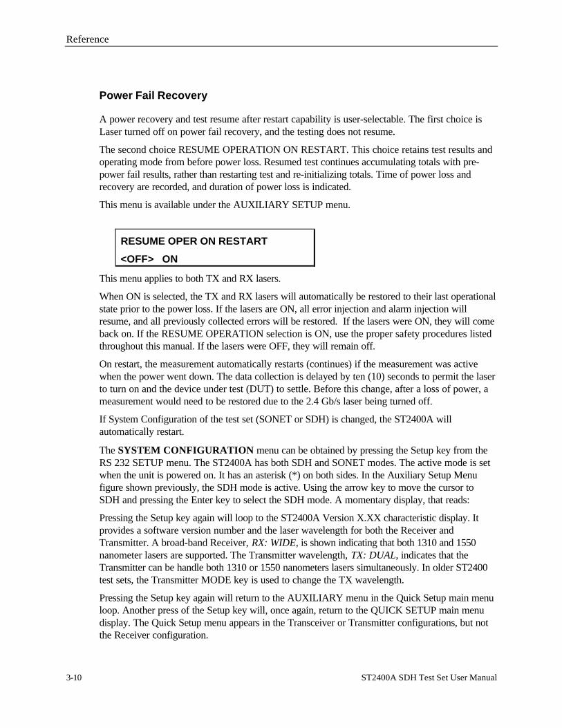
Reference
3-10 ST2400A SDH Test Set User Manual
Power Fail Recovery
A power recovery and test resume after restart capability is user-selectable. The first choice isLaser turned off on power fail recovery, and the testing does not resume.
The second choice RESUME OPERATION ON RESTART. This choice retains test results andoperating mode from before power loss. Resumed test continues accumulating totals with pre-power fail results, rather than restarting test and re-initializing totals. Time of power loss andrecovery are recorded, and duration of power loss is indicated.
This menu is available under the AUXILIARY SETUP menu.
RESUME OPER ON RESTART
<OFF> ON
This menu applies to both TX and RX lasers.
When ON is selected, the TX and RX lasers will automatically be restored to their last operationalstate prior to the power loss. If the lasers are ON, all error injection and alarm injection willresume, and all previously collected errors will be restored. If the lasers were ON, they will comeback on. If the RESUME OPERATION selection is ON, use the proper safety procedures listedthroughout this manual. If the lasers were OFF, they will remain off.
On restart, the measurement automatically restarts (continues) if the measurement was activewhen the power went down. The data collection is delayed by ten (10) seconds to permit the laserto turn on and the device under test (DUT) to settle. Before this change, after a loss of power, ameasurement would need to be restored due to the 2.4 Gb/s laser being turned off.
If System Configuration of the test set (SONET or SDH) is changed, the ST2400A willautomatically restart.
The SYSTEM CONFIGURATION menu can be obtained by pressing the Setup key from theRS 232 SETUP menu. The ST2400A has both SDH and SONET modes. The active mode is setwhen the unit is powered on. It has an asterisk (*) on both sides. In the Auxiliary Setup Menufigure shown previously, the SDH mode is active. Using the arrow key to move the cursor toSDH and pressing the Enter key to select the SDH mode. A momentary display, that reads:
Pressing the Setup key again will loop to the ST2400A Version X.XX characteristic display. Itprovides a software version number and the laser wavelength for both the Receiver andTransmitter. A broad-band Receiver, RX: WIDE, is shown indicating that both 1310 and 1550nanometer lasers are supported. The Transmitter wavelength, TX: DUAL, indicates that theTransmitter can be handle both 1310 or 1550 nanometers lasers simultaneously. In older ST2400test sets, the Transmitter MODE key is used to change the TX wavelength.
Pressing the Setup key again will return to the AUXILIARY menu in the Quick Setup main menuloop. Another press of the Setup key will, once again, return to the QUICK SETUP main menudisplay. The Quick Setup menu appears in the Transceiver or Transmitter configurations, but notthe Receiver configuration.

Reference
ST2400A SDH Test Set User Manual 3-11
General Menus and Displays
Menu and Measurement Refinements
• Extended range for B2 error rate measurement - The B2 error counter has beenupdated to read every 20 ms, instead of every 100 ms, to extend the maximum B2 error ratewhich can be measured. B2 errors will be accurately counted up to error rates of 1.0E-3 forevenly-distributed errors.
• To determine if a TX board is B3 capable, the return value from the remote command"tx_brd_rev" must be greater than or equal to 35. To determine if an RX board is B3 capable,the return value from the remote command "rx_brd_rev" must be greater than or equal to 9.Menus for B3 Path Analysis will be hidden if the proper hardware is not present in theST2400A test unit. In order to use the B3 Path Analysis functionality, it is also necessary topurchase Option 42.
• B3 Path Analysis/ J0, J1 Path Trace (displayed as ASCII text).
• Print-on Event function gives a printed error count for event seconds containing B1, B2 andB3, Pattern Bit, Path REI, Path Alarms, LOP, Path AIS, Path RDI, FEBE-L (MS-REI)errors, as well as, S1/SSM byte changes.
• Error Reporting - In both SONET and SDH mode, the ST2400A will provide Total Errors,Errored Seconds (ES), bit error rate (BER) and Severely Errored Seconds (SES) for B1, B2,B3, Payload Bit, FEBE-P (Rath RDI), and FEBE-L (MS-REI) errors. In SDH mode, theST2400A will provide Errored Blocks (EB) and Background Block Errors (BBE) for G.826error analysis measurement. In SDH mode, the ST2400A will properly detect and countConsecutively Severely Errored Seconds (CSES) per G.826. In SONET mode, SeverelyErrored Seconds (SES) will be counted based on SES criteria in GR-253-CORE.Consecutively Severely Errored Seconds will be measured for B1, B2, B3 and MS-REIerrors, and displayed in SDH mode only.
• In SDH mode, all overhead, alarms, failures, and errors are displayed or printed in ITU-Tterminology (for example, FEBE is REI, FERF is RDI).
• User shall have the ability to retransmit all editable Transport Overhead (TOH) with orwithout modification. Remaining non-editable TOH shall be retransmitted withoutmodification. B1 and B2 BIP bytes shall be re-computed in THRU mode and may be erroredat user request. Other alarms and failures may be injected at user-request.
• S1 Byte/ SSM - ST2400A includes S1 byte changes as events which can initiate print-on-event (time-stamped). When Synchronization Status Message (SSM) in S1 byte changes, atime-stamped report of SSM can be printed indicating new SSM contents. SSM byte changeswithin the S1 byte are decoded in clear text per G.707 (SDH) and GR-253 (SONET).
• 1/8th Rate Sync Output - ST-2400A shall generate a sync output signal at 1/8 data rate(311 MHz), useful for triggering scope-based eye diagram measurements. Sync output shall

Reference
3-12 ST2400A SDH Test Set User Manual
be provided on SMA connector mounted on rear panel. Sync output signal characteristics:AC-coupled, 300 mV pk-pk. Terminate externally with 50 Ohms.
• Pointers (Read-only menu under RX Trib button). Pointer Value displayed (0 to 782). PointerMeasurement Counts for Positive Pointer Justifications, Negative Pointer Justifications, NewData Flag (NDF)

Reference
ST2400A SDH Test Set User Manual 3-13
Transmitter or Receiver Configurations
The ST2400A 2.4 Gb/s SDH/SONET Test Set can be ordered in one of three configurations,which are: Transceiver, Transmitter, Or Receiver. This chapter details the menus available in theTransceiver configuration. Go to the appendix for a listing of Transmitter-only or Receiver-only ormenus.
The ST2400A shall accept zero, one or two factory-installed 2.488 Gb/s laser Transmitter modulesand/or zero or one APD Receiver module (also referred to as I/O modules). Initially, two types oflaser Transmitters – direct modulated (DM) and EA-modulated Integrated Laser Module (ILM) –shall be available.
The ST2400A shall also provide electrical input and output clock and data interfaces operating at2.488 Gb/s. Base Transceiver configuration shall provide 2.488 Gb/s electrical interfaces and155/622 Mb/s optical and electrical add/drop tributary interfaces. Transmitter configurations willnot include 155/622 optical and electrical drop interface (although unused connectors may bemounted). Receiver configurations will not include 155/622 optical and electrical add interface(although unused connectors may be mounted).
In older ST2400 units, the Transmitter version can be easily identified because it lacks theReceiver connectors for 155/622 OUT and 2.4 Gb/s IN and it will not detect a Receiver cardduring the power-on cycle. (Some early models may have all front panel connectors.) Pressingany of the control keys in the Receiver section will cause the following message to be displayed.
RX CARD NOT FOUND
RX CONTROLS DISABLED
Figure 3-3. Receiver Card Not Installed
In older ST2400 units, the Receiver version can be easily identified because it lacks theTransmitter connectors for 155/622 IN and 2.4 Gb/s OUT and it will not detect a Transmittercard during the power-on cycle. (Some early models may have all front panel connectors.)Pressing any of the control keys in the Transmitter section will cause the following message to bedisplayed:
TX CARD NOT FOUND
TX CONTROLS DISABLED
Figure 3-4. Transmitter Card Not Installed

Reference
3-14 ST2400A SDH Test Set User Manual
Error Log Display
No additional entries will be logged when the Error Log becomes full. If the Error Log is morethan 95% full when the RUN key is pressed, the message below will be displayed. Selecting NOwill allow the test to run, but when the error log is full new data will be lost. Selecting YES willclear the error log.
ERROR LOG XX% FULL
CLEAR LOG? <NO> YES
Figure 3-5. Error Log Display

Reference
ST2400A SDH Test Set User Manual 3-15
Transmitter Menus and Displays
TX Source Mode
Pressing the MODE key will access the TX MODE SELECTION menu. It is used to choose oneof the three data modes that will produce the 2.4 Gb/s output signal. The three choices are: anexternal input (EXT) from the Transmitter front panel 155 or 622 Mb/s inputs, an internally (INT)generated 2.4 Gb/s signal, or a through (THRU) mode from the Receiver's 2.4 Gb/s inputconnector. The EXT and INT modes function on both the ST2400A Transceiver and ST2400ATransmitter units. The THRU mode only functions on an ST2400A Transceiver unit.
TX MODE SELECTION
EXT <INT> THRU
Figure 3-6. Transmitter Input Menu
The EXT input can be 155 Mb/s optical (STM-1), 622 Mb/s optical (STM-4), or 155 Mb/s CMIelectrical signal. On the Transmitter 155 / 622 Input Status section there are three yellow LEDindicators, two optical and one electrical. The appropriate LED will indicate the input signal.
The INT mode generates an unequipped SDH 2.4 Mb/s (STM-16) signal with valid transportoverhead. The first column of the first STM-1 can be modified, adding alarms and errors.
ST2400A LCD Display (SDH)
INT TX MAPPPING STRUCTURE
VC4: <1> 4C 16C
The menu above will only appear in SDH measurement mode.
This menu will be available only if INTERNAL mode selected and the correct STM-4c/STM-16chardware is present. For this menu, VC4 will be automatically selected, and will be the onlyavailable mode.
This menu will not be available in “EXTERNAL” or “THRU” mode.
If “EXT” mode is selected and the TRIB channel is set to “ALL”, the “INT TX TEST PATT”menu will be unavailable.
Note
If STS48C or VC4-16C mapping is chosen, Random BER injection is limited to channel 1 only,and will be forced to channel 1 if it is not set there already. Also any errors being injected will bestopped when any mapping mode is changed.

Reference
3-16 ST2400A SDH Test Set User Manual
Any of the OC-12c/OC-48c (STM-4c/STM-16c) remote commands which areexecuted in any of the above mentioned “invalid” conditions will fail.
The THRU (Through) mode can be used to pass without modification, or modify, a2.4 Gb/s SDH signal that entered the Receiver from an external source. All three yellow statusLEDs will be off when the ST2400A is in the THRU mode.
In older ST2400 test sets, pressing the MODE key a second time will access the TXWAVELENGTH menu, if the dual wavelength Transmitter option is installed. It is used to switchbetween 1310 nm and 1550 nm.
TX WAVELENGTH
<1310 nm> 1550 nm
Figure 3-7. Transmitter Wavelength Menu (if dual wavelength TX option installed)

Reference
ST2400A SDH Test Set User Manual 3-17
External Clock Synchronization
This menu choice is available under the MODE button the front panel (TX side).
2 Mb/2 MHz inputs can be utilized for external timing synchronization. This option will only appearwhen the "INTERNAL" Transmitter mode is enabled. A "Loss of Signal" message will bedisplayed on the front panel LCD, if either of these options are selected and the signal is notpresent. If the 2.048 signal is lost from the front-panel , an error message will appear on the LCDscreen - "TX: LOSS OF 2.048 CLK", which will flash on and off in 3-second intervals.
EXTERNAL SYNC INPUT
<OFF> 2.048 1.544
Figure 3-8.External Timing Synchronization (MODE button) (SDH)

Reference
3-18 ST2400A SDH Test Set User Manual
PRBS Mappings
These menu choices are available under the MODE button the front panel (TX side).
User can select the following TX patterns as internally-generated payload:
• Fixed 00 (All-Zeros) to FF;
• 223-1, or inverted 223-1 per ITU-T O.181;
• 231-1, or inverted 231-1.
The only structured payload mappings available in SDH mode is (16 x VC-4). In SONET mode,users can select internal generated payload mapping as 1x 3 x STS-1 or 16 x STS-3c.
User can also select one of three TX patterns to fill the background of internally-generated 2.4Gbit/s signal to which externally-supplied 155 or 622 Mbits/ signal is added (EXT mode). The userhas the same background mapping selections (STS1 or STS3c in SONET,VC4 in SDH).
Payload and test patterns are compatible with ITU-T O.181.
This option will appear in both "INTERNAL" or "EXTERNAL" Transmitter modes. The firstmenu below (STS1, STS3c) will only appear in SONET measurement mode, since VC4 TestPattern is the only valid option in SDH measurement mode.
The choice between the asterisks (*) is the choice that can be selected. Press the ENTER key tobring up other choices.
INT TX MAPPING STRUCTURE
VC4: <1> 4C 16C
OR
INT TX VC4 TEST PATT
FIXED <00> *PRBS <23O181>*
OR
EXT TX VC4 TEST PATT
FIXED <00> *PRBS <23O181>*
Figure 3-9. PRBS Mappings (MODE button) (SDH)

Reference
ST2400A SDH Test Set User Manual 3-19
Input Select, Transmitter
EXT TRIB INPUT SELECT
<155> 622 155e
Figure 3-10. Input Select Menu
The Transmitter SELECT key is used to pick one of three tributary choices when the MODE isset to EXT (external). The input can be 155 Mb/s (STM-1) optical, 622 Mb/s (STM-4) optical, or155 Mb/s CMI electrical signal source from the appropriate connector.
Tributary Select, Transmitter
The TRIB key on the Transmitter side is used to select how the external source (tributary) will bemultiplexed into the 2.4 Gb/s signal.
EXT 155 Mb/s TRIB INSERT
SINGLE <nn> ALL
OR
EXT 622 Mb/s TRIB INSERT
SINGLE <n> ALL
Figure 3-11. Transmitter Tributary Select Menus
A choice is offered between multiplexing the tributary into one specific channel or into all available2.4 Gb/s channels. This menu depends on the choice that was made in the Input Select menu—155, 622, or 155e (CMI).
• The first menu is the 155 Mb/s tributary insert menu that is used to select betweenmultiplexing the external source tributary into 1 of 16 channels or all 16 channels of the 2.4Gb/s signal. It refers to both the optical and electrical (CMI) 155 Mb/s Transmitter inputsignals.
• The second menu is the 622 Mb/s tributary insert menu that is used to select betweenmultiplexing the external source tributary into 1 of 16 channels or all 16 channels of the 2.4Gb/s signal. It refers to the optical tributary source.

Reference
3-20 ST2400A SDH Test Set User Manual
Illegal Mode
* * * TX MODE * * *
EXT MUST BE SELECTED
Figure 3- 12. Transmitter Alarms
If the TRIB or INPUT SELECT keys are pressed when the Transmitter is in the INT (internal) orTHRU (through) mode, the illegal mode display will be exhibited for three seconds and thenswitched to the TX MODE SELECTION menu.

Reference
ST2400A SDH Test Set User Manual 3-21
Alarm Generation Menus—SDH
The left column shows the four SDH alarm displays that will be scrolled in a loop each time theTransmitter alarm key is pressed. The right side shows the same alarm displays when thecontinuous mode is being accessed. The arrow keys, increment and decrement keys, and theEnter key are used to modify the alarm conditions and access the continuous displays.
LOSS OF SIGNAL<OFF> nnn usec x.xSec
ERRORED FRAME<OFF> nnnFRAMES x.xSec
MS RDI<OFF> nnnFRAMES x.xSec
MS AIS<OFF> nnnFRAMES x.xSec
INJECT xxxx 2.5s OFF ENABLE WAIT 2.5s
LOSS OF SIGNAL<OFF> nnn usec <CONT>
ERRORED FRAME<OFF> nnnFRAMES <CONT>
MS RDI<OFF> nnnFRAMES <CONT>
MS AIS<OFF> nnnFRAMES <CONT>
Figure 3-13. Transmitter Alarms SDH
The Transmitter ALARM key is used to select one of the five alarm menus, four on the left, andone centered at the bottom LOS (Loss Of Signal), ERRORED FRAME, MS RDI, MS AIS, andINJECT. The alarm menus are used to set specific parameters simulating various synchronizationdefects as detailed below.
Each of the first four Transmitter alarm menus have the following parameters:
• OFF—The alarm is disabled.
• nnn µsec (or nnn FRAMES): Sets the duration of the alarm in microseconds for the LOSalarm or frames for the other alarms. Position the cursor using the left and right arrow keys.Use the INC and DEC keys to change the value from 1 to 127 microseconds or frames.Press the Enter key to generate the alarm.
• x.xSec: Sets the on time for the burst operation from 0.1 to 9.9 seconds. This alarm conditiongenerates extensive signal failure. Each time the Enter key is pressed an asterisk (*) and theword ACTIVE will be displayed in the upper right side of the display. Use the arrow keys toposition the cursor, and the INC and DEC keys to change values. This field changes to CONT,when the value is incremented beyond 9.9 seconds. Or when the cursor positioned under the

Reference
3-22 ST2400A SDH Test Set User Manual
letter S in the x.xSec and the increment key is pressed. The DEC key is used to return to this(x.xSec) value.
• CONT: Turns the alarm condition on continuously, generating a hard failure. To access thishidden field see x.xSec above. Pressing the Enter key will turn on the alarm continuously,displaying an asterisk (*) and the word ACTIVE. Use the right arrow key to move the cursorto OFF and the Enter key to turn the alarm off. Then use the left arrow key to move thecursor back to CONT and the Enter key to activate the alarm. Using the alarm key to leavethe menu will not turn the alarm off.
The INJECT xxxx alarm menu, permits recurring alarm conditions to be set. Position the cursorunder the alarm—xxxx in this case—and use the increment key to select the alarm type. Then setthe alarm INJECT (on time) period from 0.1 to 9.9 seconds, and the WAIT (off time) for a periodfrom 1.0 to 30.0 seconds. An asterisk (*) will switch between the wait and inject states, replacingthe letter s, indicating which is the active state. Only one alarm condition can be activated at any onetime. Enabling the recurring alarm will disable any other active alarm. Moving the cursor to OFF andpressing the Enter key will stop the alarm cycle. When off, the letter s will appear at the end of bothtop and bottom LCD display lines.

Reference
ST2400A SDH Test Set User Manual 3-23
Overhead Menus (SDH), Transmitter
OVHDKey
RS TRACE J0PASS <SET 00>
RS EOW E1PASS <SET F7>
RS USER F1PASS <SET 00>
RS DCC D1 D2 D3PASS <SET 00 00 00>
RS APS K1 K2 APSPASS <SET 00 00> EDIT
RS DCC D4 D5 D6PASS <SET 00 00 00
MS SSMB S1 MSGPASS <SET 00 (msg)>
MS REI M1PASS <SET 00>
MS EOW E2PASS <SET 7F>
RS DCC D7 D8 D9PASS <SET 00 00 00>
RS DCC D10 D11 D12PASS <SET 00 00 00
RS TRACE J0<PASS> SET --
RS EOW E1<PASS> SET --
RS USER F1<PASS> SET --
RS DCC D1 D2 D3<PASS> SET -- -- --
PATH SIG LABEL C2<PASS> SET
MS DCC D4 D5 D6<PASS> SET -- -- --
MS SSMB S1 MSG<PASS> SET -- ---
MS REI M1<PASS> SET --
MS EOW E2<PASS> SET --
MS DCC D7 D8 D9<PASS> SET -- -- --
MS DCC D10 D11 D12<PASS> SET -- -- --
APS **** 1+1 RQ- 0 SW- 0 0 No Request
Direction
Protection
Request Line
Switch Line
Message
MS APS K1 K2 APS<PASS> SET -- -- EDIT
Figure 3-14. Transmitter Overhead (SDH)
The Transmitter overhead byte menus can be used to pass or change the 2.4 Gb/s signal overheadbytes, in the first column of the STM-1. The Transmitter OVHD (overhead) key is used to scrollthrough the Regenerator Section (RS) and Multiplexer Section (MS) overhead bytes. The top lineof each display identifies the designated SDH overhead byte. The bottom line is used to eitherPASS or SET (change) the value. When the cursor is on PASS the byte is hidden. When thecursor is moved to SET the byte value is displayed and the Enter key LED starts to flash. Use thearrow keys to move the cursor, and the INC and DEC keys to change values. Pressing the Enterkey or the overhead key will store the value.
Bytes D4 through D12 are passed or set as a group. Each can be individually changed, using theINC and DEC keys, but pressing the Enter key to SET any one of them will set all of them.Passing any one will pass them all.
For the path overhead, C2 byte is added at TX (Path Signal Label C2)) - Identifies High OrderPath Label Unequipped and High Order Path Label Mismatch. C2 byte can be set to any valuefrom 0x00 to 0xFF.

Reference
3-24 ST2400A SDH Test Set User Manual
Select the EDIT command from the MS APS menu to access and change the AutomaticProtection Switching bytes illustrated on the right side of the figure. Position the cursor over theword EDIT, press the Enter key and the APS menu in will be displayed. Use the arrow, INC,DEC, and ENTER keys to select, change, and store values. Press the OVHD key to return to theMS APS menu.
Ability to edit J0 Multi-Byte Trace
J0 Trace Generation (TX); Capture & Display (RX)
J0 Trace provides a capability to uniquely identify each of the multiple channels being carried in aDense Wave Division Multiplexer (DWDM) system, providing an end-to-end continuity check.Since only the SONET framing byte plus J0 are in the unscrambled overhead of the SONETsignal, it is possible to extract for display the J0 trace to confirm channel ID.
ST2400A ability to generate unique J0 traces allows test signals to be easily identified, or allowstest signals to simulate network-element generated traffic without Trace Identifier Mismatch(TIM) alarm being generated. ST2400A ability to display received J0 trace allows users to verifycontinuity and correct routing of individual channels within multi-channel DWDM system.
ITU-T has established a standard for 16-byte J0 trace. GR-253 has no multi-byte J0 standard, butJ0 Trace is listed as an open issue in most recent List Report (GR-253-ILR, Issue 2B, Dec 97).Some vendors are promoting 64-byte trace matching SONET J1 trace standard in GR-253-CORE.
ST2400A ability to generate non-standard-compliant 16-byte and 64-byte traces allowsmanufacturers to test network element response in presence of invalid trace (for example, 16-bytewithout valid frame start marker or with incorrect CRC; 64-byte without <CR><LF> termination).
J0 Trace Generation (TX)
When single-byte SET selected, user may set the value of J0 byte between 0 and 255. Factorydefault is 01.
When 16-byte SET selected, the first byte is set to frame start marker containing CRC-7calculated over the 15 remaining bytes per ITU-T G.707 section 9.2.2.2. User is able to view/editthe CRC and the ASCII contents of the remaining 15-bytes. Factory default is valid frame startmarker followed by “Tek ST2400A<4 NULLs>”. 16-byte trace value is saved in non-volatilememory and restored on power-up (to eliminate need for users to always go through acumbersome process to set it up.
When 64-byte SET selected, user is able to set the J0 trace per the requirements of GR-253-CORE for J1 traces (Issue 2, Dec 1995, section 6.2.3.2.3.A, STS Path Trace). User is able to setall 64 bytes to any hex value from 00-FF. If the user enters less than 62 characters, the ST-2400Ashall pad the remainder with NULL characters. A <CR> and a <LF> is added to the end of themessage, creating the 64-byte trace message. Factory default 64-byte trace message is “TekST2400A<51 nulls><CR><LF>”. 64-byte trace value is saved in non-volatile memory andrestored on power-up.

Reference
ST2400A SDH Test Set User Manual 3-25
J0 Generation Front Panel Implementation
Allow user to PASS J0 through, SET it to single byte hex value, set it to 16Byte value, or set it to64Byte value as shown:
SECT TRACE J0
<PASS> SET nn EDIT
When PASS is selected, and TX is in EXT mode, J0 in received added tributary is inserted in J0 ofoutput 2.5 Gb/s signal.
When PASS is selected and TX is in THRU mode, J0 in received 2.5 Gb/s signal is retransmittedin J0 of output 2.5 Gb/s signal.
When PASS is selected and TX is in INT mode, J0 is set to single byte 01.
When “SET nn” is selected, nn should display currently selected single byte J0 as two hex digits.User may set single byte J0 to any value in range 0 - 255 (00 - FF hex).
When “EDIT” is selected and ENTER is pressed, user is able to select between 16-byte ITU-formatted trace, and 64-byte trace as shown below:
J0 TRACE SELECTION
<16 BYTE> 64 BYTE
When 16-byte trace is selected, 15 editable bytes of 16-byte trace are set to first 15 bytes of tracein memory. If 16-byte trace was most recently used, previous trace is restored. If 64-byte tracewas most recently used, these 15 bytes are set to first 15 bytes of previously used 64-byte trace.Correct frame start marker is computed and displayed in hex in “nn” portion of CRC-nn.
Factory default trace is “Tek ST2400A<4 NULLs>”.
When CLR is selected, 15 editable bytes of 16-byte trace is cleared to null (hex 00), and correctframe start marker is computed and displayed in hex in “nn” portion of CRC-nn.
When trace characters are selected, left arrow, right arrow, INC, DEC, and ENTER are used tonavigate trace and edit characters. Full set of upper case, lower case, digits, and punctuation isselectable. The hexadecimal equivalent of each character selected on the second row will beupdated in the “HEX=” field on the first row, as shown below.

Reference
3-26 ST2400A SDH Test Set User Manual
If the character being edited on the second row is less than 0x20 hex or greater than 0x7F hex,the character will be displayed as a filled in box in the center of the field, the correct value will stillbe displayed in the “HEX=” field.
16 BYTE <EDIT> CLR HEX=54
TEK ST2400A CRC=F4
When 64-byte trace is selected, 62 editable bytes of 64-byte trace are set to bytes stored in 64-byte trace memory. Last two bytes are set to <CR><LF>. Factory default trace is “Tek
When CLR is selected, 62 editable bytes of 64-byte trace are cleared to nulls (hex 00), and<CR><LF> is placed in last two characters.
When trace characters are selected, left arrow, right arrow, INC, DEC, and ENTER are used tonavigate trace and edit characters. If trace contains non-printable ASCII characters, thosecharacters are displayed as a filled in box.
When cursor is in right-most character position and right arrow key is pressed, trace is shifted leftso character and cursor – previously in right-most character position – now appear in left-mostcharacter position, with 21 following characters displayed in remaining positions. As shownbelow, arrow indicator is displayed in left-most and/or right-most display position when precedingor following trace characters are available to be displayed by scrolling left or right:
ßß64 BYTE <EDIT> CLR HEX=54àà
ST2400A

Reference
ST2400A SDH Test Set User Manual 3-27
J0, J1 Trace Capture and Display (RX)
ST-2400A is able to capture J0 and J1 trace on a sampled basis for display. User is able to selectthe expected trace length / type as single-byte, 16-byte, or 64-byte. When trace display isselected, J0 trace is sampled and display updated at least four times per second.
16-byte trace selection shall expect 16-byte trace matching format specified in G.707 / G.831.Trace is displayed either as 15-byte ASCII string, or as hex value of frame start marker followedby 15-byte ASCII string. ST-2400A must recognize frame start marker and display 15-ASCIIcharacters in sequence, assuming identical 16-byte trace is being repetitively received.
No CRC error detection capability is provided in 16-byte trace mode.
64-byte trace selection expects 64-byte trace matching format specified for STS Path Trace inGR-253-CORE (as described above for TX). Trace is displayed as 64 byte ASCII string (with<CR><LF> indicated as their Hexadecimal values).
No Trace Identifier Mismatch (TIM) detection is provided in single-byte, 16-byte or 64-byte tracemode.
J0, J1 Trace Capture and Display Front Panel Implementation (RX)
ST2400A displays single byte J0 and J1, as shown below:
RX TOH A1 A2 J0 J1
F6 28 01 00
If multi-byte trace is received, J0 and J1 can be expected to change frequently, when single bytedisplay is selected.
The J0 and J1 trace selection menus are the last menus in the queue of RX overhead menus. Useris able to select between display of 16-byte or 64-byte trace, as follows:
J0 TRACE SELECTION
<16 BYTE> 64 BYTE
J1 TRACE SELECTION
<16 BYTE> 64 BYTE

Reference
3-28 ST2400A SDH Test Set User Manual
When 16-Byte is selected (as shown above), frame start marker (if found, based on detection ofcharacter with MSB set) is displayed in hex, along with 15-byte ASCII trace. Non-printablecharacters are displayed as boxes (). If a frame start marker is found, the trace will be alignedand 16 captured bytes are displayed in captured order, as follows:
The left and right arrow keys can be used to scroll forward / backward through the 16 byte traceand the CRC, the “HEX=” will be properly updated.
16 BYTE <EDIT> CLR HEX=54
TEK ST2400A CRC=F4
When 64-Byte is selected (as shown below), first 22 characters following <CR><LF> is displayedas shown. Non-printable characters is displayed as boxes (). If no<CR><LF> can be found,captured 64 bytes are displayed in captured order with no error indication. NOTE: Subsequentdisplay updates will likely cause frequent trace content changes if no valid trace containing CR /LF can be found.
ßß 64 BYTE <EDIT> CLR HEX=54àà
TEK ST2400A
User is able to use left and right arrow keys to scroll forward / backward through 64-byte trace.
NOTE: At the end of a valid 64byte trace, in the 63rd and 64th positions the <CR> and <LF> willbe represented in the “HEX=” field as 0D and 0A respectively.

Reference
ST2400A SDH Test Set User Manual 3-29
Ability to edit M1 Byte
MS-REI M1
<PASS> SET 00
Figure 3-15. Transmitter Overhead (OVHD button) (SDH)
The Transmitter overhead byte menus can be used to pass or change the 2.4 Gb/s signal overheadbytes, in the first column of the STM-1. The Transmitter OVHD (overhead) button, on the lowerleft side of the ST2400A front panel, is used to scroll through the Regenerator Section (RS) andMultiplexer Section (MS) overhead bytes. The top line of each display identifies the designatedSDH overhead byte. The bottom line is used to either PASS or SET (change) the value. When thecursor is on PASS, the byte is hidden. When the cursor is moved to SET the byte value isdisplayed and the Enter key LED starts to flash. Use the arrow keys to move the cursor, and theINC and DEC keys to change values. Pressing the Enter key or the overhead key will store thevalue. The value of the editable M1 byte can range from 00 to FF.
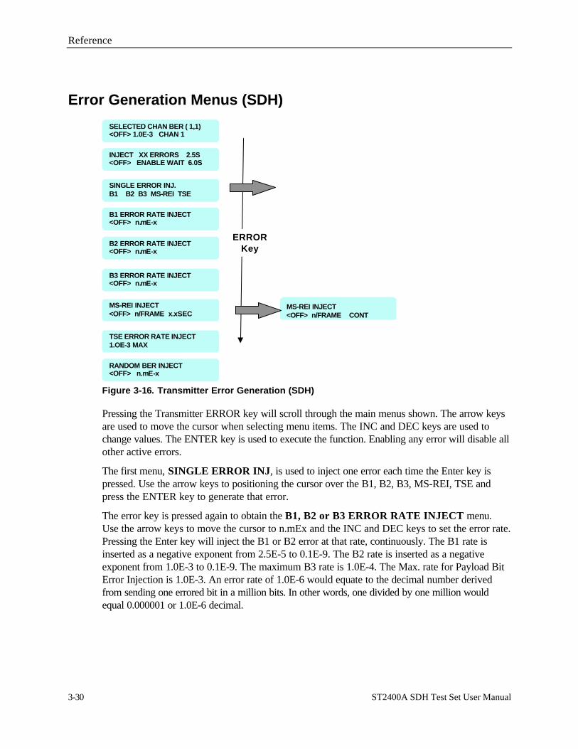
Reference
3-30 ST2400A SDH Test Set User Manual
Error Generation Menus (SDH)
SINGLE ERROR INJ.B1 B2 B3 MS-REI TSE
MS-REI INJECT<OFF> n/FRAME CONT
INJECT XX ERRORS 2.5S<OFF> ENABLE WAIT 6.0S
B1 ERROR RATE INJECT<OFF> n.mE-x
MS-REI INJECT<OFF> n/FRAME x.xSEC
RANDOM BER INJECT<OFF> n.mE-x
SELECTED CHAN BER ( 1,1)<OFF> 1.0E-3 CHAN 1
B2 ERROR RATE INJECT<OFF> n.mE-x
ERRORKey
TSE ERROR RATE INJECT1.OE-3 MAX
B3 ERROR RATE INJECT<OFF> n.mE-x
Figure 3-16. Transmitter Error Generation (SDH)
Pressing the Transmitter ERROR key will scroll through the main menus shown. The arrow keysare used to move the cursor when selecting menu items. The INC and DEC keys are used tochange values. The ENTER key is used to execute the function. Enabling any error will disable allother active errors.
The first menu, SINGLE ERROR INJ, is used to inject one error each time the Enter key ispressed. Use the arrow keys to positioning the cursor over the B1, B2, B3, MS-REI, TSE andpress the ENTER key to generate that error.
The error key is pressed again to obtain the B1, B2 or B3 ERROR RATE INJECT menu.Use the arrow keys to move the cursor to n.mEx and the INC and DEC keys to set the error rate.Pressing the Enter key will inject the B1 or B2 error at that rate, continuously. The B1 rate isinserted as a negative exponent from 2.5E-5 to 0.1E-9. The B2 rate is inserted as a negativeexponent from 1.0E-3 to 0.1E-9. The maximum B3 rate is 1.0E-4. The Max. rate for Payload BitError Injection is 1.0E-3. An error rate of 1.0E-6 would equate to the decimal number derivedfrom sending one errored bit in a million bits. In other words, one divided by one million wouldequal 0.000001 or 1.0E-6 decimal.

Reference
ST2400A SDH Test Set User Manual 3-31
The MS-REI INJECT menu has three functions:
• A number of MS-REI errors can be injected into one frame. The ERROR key is used toselect the menu, and the arrow keys are used to position the cursor over the n/FRAME (n perframe) field. The number of MS-REI errors per frame can be set from 1 to 255 using the INCand DEC keys. Pressing the Enter key while this field is selected will insert that number into asingle frame.
• Move the cursor to x.xSEC and use the INC and DEC keys to set the period from 0.1 to 9.9seconds. Pressing the ENTER key when the cursor is in the x.xSEC position will inject thenumber of MS-REI errors (n/FRAME) for the period (x.xSEC), effecting multiple frames. Forexample, one MS-REI per frame could be injected for 9.9 seconds. An asterisk and the wordACTIVE will be displayed for the duration of the MS-REI injection.
• Moving the cursor under the letter s in x.xSec or pressing the INC key when the period is setto 9.9 seconds will access the CONT (continuous) command, shown on the lower right side ofthe figure. Positioning the cursor over CONT and pressing the Enter key will insert thenumber of MS-REI (n/FRAMES), continuously. An asterisk and the word ACTIVE will bedisplayed indicating that the error is being injected. Use the right arrow key to move thecursor to OFF and press ENTER. The asterisk and the word ACTIVE will no longer bedisplayed, indicating the error injection is off.
The RANDOM BER (Bit-Error-Rate) INJECT main menu is used to set the rate to a numberfrom 1.0E-3 to 0.1E-9. Pressing the Enter key will inject errors at that rate on different STM-16channels, selected at random.
The Selected Channel BER (Bit Error Rate) main menu is used to set the rate to a negativeexponent from 1.0E-3 to 0.1E-9 for the CHAN (channel) selected. Positioning the cursor over theselected channel (CHAN cc) in the lower right field and use the INC and DEC keys to select theSTM-1 channel number.
The INJECT XX ERROR menu, permits recurring error conditions to be set. Position the cursorunder the XX and use the INC key to select the error type. The INJECT period (on time) islocated in the top right field, 2.5S in this case. It can be set from 0.1 to 9.9 seconds. The WAITperiod (off time) is in the lower right field, 6.0S in this case. It can be set from 1.0 to 30.0seconds. The rates are set in each individual menu, B1, B2, B3, MS-REI, RANDOM BER, andCHANxx BER. An asterisk (*) will switch between the wait and inject states, indicating which isactive. Only one error condition can be activated at any one time.
NOTE: Bit Error Rates are inserted as a negative exponent. An error rate of 1.0E-6 would equateto the decimal number derived from sending one errored bit in a million bits. In other words, onedivided by one million would equal 0.000001 or 1.0E-6 decimal.

Reference
3-32 ST2400A SDH Test Set User Manual
B2 or B3 Error Inject (Single, All channels simultaneously)
This menu choice is available under the ERROR button on the front panel (TX side).
The user of this test unit can inject a single B1 or B2 error (one B1 or B2 error in fixed channel of2.4 Gbit/s payload), or the user an inject B1 or B2 errors simultaneously in all channels of2.4 Gbit/s payload. B2 error rates may be generated over the range 1.0E-3 to 0.1E-9.
SINGLE ERROR INJECT
B1 <B2> B3 MS-REI TSE
B2 ERROR RATE INJECT
<OFF> 1.0E-5
B3 ERROR RATE INJECT
<OFF> 1.0E-4 MAX.
The following are contained in one menu.
INJECT B2 ERRORS 2.5 s
<OFF> ENABLE WAIT 1.0 s
INJECT B3 ERRORS 2.5 s
<OFF> ENABLE WAIT 1.0 s
INJECT TSE 2.5 s
<OFF> ENABLE WAIT 1.0 s
Figure 3-17. Transmitter Error Generation (ERROR button) (SDH)

Reference
ST2400A SDH Test Set User Manual 3-33
Pressing the Transmitter ERROR key on the lower left side of the ST2400A front panel will scrollthrough the available menus. The arrow keys are used to move the cursor when selecting menuitems. The INC and DEC keys are used to change values. The ENTER key is used to executethe function. Enabling any error will disable all other active errors.
The SINGLE ERROR INJ menu, is used to inject one error each time the Enter key is pressed.Use the INC key to position the cursor over the B1, B2, FEBE-L, BIT, or CH (Channel), andpress the ENTER key to generate that error. When the cursor is positioned over B1, press theINC key again to change to the B2 byte.
The next menu permits injecting a single B2 error into all channels.
Press the ERROR key to move to the next menu, B2 ERROR RATE INJECT. Use the arrowkeys to move the cursor to 1.0E-5 and the INC and DEC keys to set the error rate. Pressing theEnter key will inject the B2 error at that rate, continuously.
Inject Random BER on one Selectable Channel
This menu choice is available under the ERROR button on the front panel (TX side).
The user of this test unit can inject a random bit error rate on one selectable channel.
SELECTED CHAN BER ( 1,1)
<OFF> 1.0E-3 CHAN 1
Figure 3-18. Random BER on one Selectable Channel (ERROR button) (SDH)

Reference
3-34 ST2400A SDH Test Set User Manual
Receiver Menus and DisplaysError Measurements (SDH), Receiver
Press ENTER key again and again to cycle through the choices.
RS-B1 Measurement
RS ES = 0 BER = 1.0e-04
B1 SES = 0 TOT = 0
The Enter key will flash while at the menu above. Pressing the Enter key permits access to thefollowing sub-menus.
RS EB = 0 CSES 0
B1 BBE = 0
RS BBER ESR = 0.0E-00
B1 0.00E-00 SESR = 0.0E-00
RS AEB = 0 AES = 0
B1 ABBE = 0 ASES = 0
RS UAS = 0
B1 UR = 0.0E-00

Reference
ST2400A SDH Test Set User Manual 3-35
MS-B2 Measurement
MS ES = 0 BER = 1.0e-04
B2 SES = 0 TOT = 0
The Enter key will flash while at the menu above. Pressing the Enter key permits access to thefollowing sub-menus.
MS EB = 0 CSES 0
B2 BBE = 0
MS BBER ESR = 0.0E-00
B2 0.00E-00 SESR = 0.0E-00
MS AEB = 0 AES = 0
B2 ABBE = 0 ASES = 0
MS UAS = 0
B2 UR = 0.0E-00

Reference
3-36 ST2400A SDH Test Set User Manual
HP-B3 Measurement
HP ES = 0 BER = 1.0e-04
B3 SES = 0 TOT = 0
The Enter key will flash while at the menu above. Pressing the Enter key permits access to thefollowing sub-menus.
HP EB = 0 CSES 0
B3 BBE = 0
HP BBER ESR = 0.0E-00
B3 0.00E-00 SESR = 0.0E-00
HP AEB = 0 AES = 0
B3 ABBE = 0 ASES = 0
HP UAS = 0
B3 UR = 0.0E-00

Reference
ST2400A SDH Test Set User Manual 3-37
MS-REI Measurement
MS ES = 0 BER = 1.0e-04
REI SES = 0 TOT = 0
The Enter key will flash while at the menu above. Pressing the Enter key permits access to thefollowing sub-menus.
MS EB = 0 CSES 0
REI BBE = 0
MS BBER ESR = 0.0E-00
REI 0.00E-00 SESR = 0.0E-00
MS AEB = 0 AES = 0
REI ABBE = 0 ASES = 0
MS UAS = 0
REI UR = 0.0E-00

Reference
3-38 ST2400A SDH Test Set User Manual
HP-REI Measurement
HP ES = 0 BER = 1.0e-04
REI SES = 0 TOT = 0
The Enter key will flash while at the menu above. Pressing the Enter key permits access to thefollowing sub-menus.
HP EB 0 CSES= 0
REI BBE 0
HP BBER ESR = 0.0E-00
REI 0.00E-00 SESR = 0.0E-00
HP AEB = 0 AES = 0
REI ABBE = 0 ASES = 0
HP UAS = 0
REI UR = 0.0E-00

Reference
ST2400A SDH Test Set User Manual 3-39
TSE Measurement
TSE ES = 0 BER = 1.0e-04
SES = 0 TOT = 0
The Enter key will flash while at the menu above. Pressing the Enter key permits access to thefollowing sub-menus.
TSE EB 0 CSES= 0
BBE 0
TSE BBER ESR = 0.0E-00
0.00E-00 SESR = 0.0E-00
TSE AEB = 0 AES = 0
ABBE = 0 ASES = 0
TSE UAS = 0
UR = 0.0E-00

Reference
3-40 ST2400A SDH Test Set User Manual
Totals
RS-B1 MS-B2 HP-B3
0 0 0
MS-REI HP-REI TSE
0 0 0
ELAPSED TIME
D HH:MM:SS
The ERROR key on the Receiver side of the front panel is used to scroll through the LCDdisplays on the left side. The Enter key on the right side of the LCD display is used to access a setof submenus for each of the first three main menus—RS-B1, MS-B2, HP-B3, MS-REI,HP-REI, and TSE Measurement. Errors that were detected on the 2.4 Gb/s SDH signal aredisplayed in the RS-B1, MS-B2, and HP-B3, MS-REI, HP-REI, and TSE error summary menus.These errors are totaled in the fourth menu. The last menu on the lower left will display theelapsed test time in: days, hours, minutes, and seconds. Each press of the error key will cycle tothe next error display in a continuous loop, until some other key is pressed.

Reference
ST2400A SDH Test Set User Manual 3-41
Error Measurement Details
• Error Reporting - In both SONET and SDH mode, the ST2400A will provide Total Errors,Errored Seconds (ES), bit error rate (BER) and Severely Errored Seconds (SES). for B1, B2,B3, FEBE-L (MS-REI), FEBE-P (HP-REI) and Payload Bit (TSE) errors. In SDH mode, theST2400A will provide Errored Blocks (EB) and Background Block Errors (BBE) for G.826error analysis measurement. In SDH mode, the ST2400A will properly detect and countConsecutively Severely Errored Seconds (CSES) per G.826. In SONET mode, SeverelyErrored Seconds (SES) will be counted based on SES criteria in GR-253-CORE.Consecutively Severely Errored Seconds will be measured for B1, B2, B3 and MS-REIerrors, and displayed in SDH mode only.
• In SDH mode, all overhead, alarms, failures, and errors are displayed or printed in ITU-Tterminology (for example, FEBE is REI, FERF is RDI, etc.).
• The RS-B1, MS-B2, HP-B3, MS-REI, HP-REI and TSE summary menus include: the EB(Errored Blocks) which is the error count; the BBE (Background Block Errors); the ES(Errored Seconds); and the SES (Severely Errored Seconds). These measurements conformto the ITU G.826 standard.
• The submenu BBER (Background Block Error Ratio); ESR (Errored Seconds Ratio); andSESR (Severely Errored Seconds Ratio) conforms to the ITU G.826 standard.
• The submenu AEB, ABBE, AES, and ASES, are the Errored Blocks; Background BlockErrors; Errored Seconds; and Severely Errored Seconds counted during Available time—conforming to the ITU M.2101 standard.
• The menu UAS (Unavailable Seconds) count and UASR (Unavailable Seconds Ratio)conform to the ITU G.827 standard.
G.826 and M.2101 Measurements in SDH Mode
In SDH mode, the following measurements are calculated for each of the B1, B2, and MS-REIerror types:
TOT (Total Errors) Total number of errors detected since testing was started (or restarted).
BER (Bit Error Ratio) Ratio of number of errors detected to the number of bits monitored forerrors since testing was started (or restarted). (Computed only for B1, B2 errors; Not computedfor MS-REI errors.). HP-REI ES can occur with HP-RDI.
ES (Errored Seconds) Number of seconds since testing was started (or restarted) in which oneor more errors were detected. B3 ES can occur with LOP or Path AIS.
SES (Severely Errored Seconds) Number of seconds since testing was started (or restarted)in which the number of detected errors exceeded the severely errored second threshold or inwhich a relevant defect was detected. Relevant defects are: LOS (all SES), LOF (all SES), MS-AIS (B2 and MS-REI SES only), and MS-RDI (MS-REI SES only). SES threshold is currentlyset to 30% of the blocks (SDH frames) per second for B1, B2, and MS-REI errors. (Thresholds

Reference
3-42 ST2400A SDH Test Set User Manual
follow G.826 recommendation, but do not conform to draft new recommendation G.epmrs, “ErrorPerformance Events for SDH Multiplex and Regenerator Sections”, which recommend 30%threshold for B1 errors, but 15% threshold for B2 and MS-REI errors.)
CSES (Consecutive Severely Errored Seconds) Count of Consecutive Severely ErroredSecond periods. A CSES period is defined as a period of more than 2, but less than 10,consecutive SES.
EB (Errored Blocks) The number of SDH frames in which one or more errors of the selectedtype were detected since testing was started (or restarted). SDH frames occur at a rate of 8000per second. Per ITU-T G.826, Errored Blocks should count one EB for each frame in which oneor more errors are detected, but may count the total number of errors detected per frame (seeG.826 C.1.5). The ST-2400 and ST-2400A count EBs as the total number of errors detected.
BBE (Background Block Errors) The number of errored blocks not occurring during SES orUnavailable time.
BBER (Background Block Error Ratio) The ratio of Background Block Errors (BBE) tototal blocks in available time since testing was started (or restarted). The count of total blocksexcludes all blocks during SESs.
ESR (Errored Second Ratio) The ratio of Errored Seconds (ES) to total seconds in availabletime since testing was started (or restarted).
SESR (Severely Errored Second Ratio) The ratio of Severely Errored Seconds (SES) to totalseconds in available time since testing was started (or restarted).
AEB (Available Errored Blocks) Number of Errored Blocks (EB) counted during availabletime.
ABBE (Available Background Block Errors) Number of Background Block Errors (BBE)counted during available time.
AES (Available Errored Seconds) Number of Errored Seconds (ES) counted during availabletime.
ASES (Available Severely Errored Seconds) Number of Severely Errored Seconds (SES)counted during available time.
UAS (Unavailable Seconds) The number of seconds during which error performance was suchthat the received signal was deemed to be unavailable (see definition of available and unavailabletime below).
UR (Unavailable Seconds Ratio) The ratio of unavailable seconds to total time since testingwas started (or restarted).
Definition of Available and Unavailable Time (per G.826) Received signal becomesunavailable when 10 consecutive severely errored seconds are detected. The 10 consecutive SESrequired to enter the unavailable state are considered unavailable seconds. The signal remains inthe unavailable state until 10 consecutive non-severely errored seconds are detected. The 10consecutive non-severely errored seconds are considered part of the available time.

Reference
ST2400A SDH Test Set User Manual 3-43
Overhead Displays (SDH), Receiver
OVHDKey RX OH D1 D2 D3 C2
00 00 00 00
RX OH H1 H2 H3 G1 00 00 00 00
RX OH B2 K1 K2 F2 00 00 00 00
RX OH S1 MSG Z2 E2 N100 **** 00 00 00
APS **** 1+1 RQ- 0 SW- 0 0 No Request
RX OH D4 D5 D6 H4 00 00 00 00
RX OH D7 D8 D9 Z3 00 00 00 00
RX OH A1 A2 J0 J1 00 00 00 00
RX OH B1 E2 F1 B3 00 00 00 00
RX OH D10 D11 D12 Z4 00 00 00 00
LOS DURATION = 2422msLOF DURATION = 2428ms
JO TRACE SELECTION<16 BYTE> 64 BYTE
J1 TRACE SELECTION<16 BYTE> 64 BYTE
Figure 3-19. Receiver Overhead LCD Displays
The ten displays are RX OH SDH overhead bytes in the first column of the first STM-1 frame.They can be displayed by pressing the OVHD key on the Receiver panel. Each time the key ispressed the next group of overhead bytes will be displayed in a continuous loop, until some otherkey is pressed.

Reference
3-44 ST2400A SDH Test Set User Manual
There are nine displays of four bytes each. The ninth display provides the ASCII synchronizationmessages, the tenth display is the APS message, the eleventh display shows the amount of time, inmicroseconds, of the Loss of Signal (LOS) and Loss of Frame (LOF), and the twelve andthirteenth displays permit J0 and J1 trace selection menus with selection of 16 byte or 64 bytetrace.
B3 path trace capability adds the following bytes: J1; B3; C2; G1; F2; H4; F3; K3; and, N1. Theseoverhead bytes are only displayed with the B3 path trace capability.
ASCII Synchronization Messages—S1 byte
For convenience both the SONET and SDH modes are compared below. The S1 byte is inhexadecimal. The unused SONET values are left blank. The unknown SDH value is marked withthree question marks and unused codes are marked RES (reserved).
S1 Byte SONET SDH S1 Byte SONET SDH00 STU ??? 08 812L01 PRS RES 09 RES02 811 0A ST3 RES03 RES 0B SETS04 812T 0C SMC RES05 RES 0D RES06 RES 0E RES RES07 ST2 RES 0F DUS DNU
S1 Byte/ SSM - ST2400A includes S1 byte changes as events which can initiate print-on-event.When Synchronization Status Message (SSM) in S1 byte changes, a time-stamped report of SSMcan be printed indicating new SSM contents.
SSM byte changes are decoded in clear text per G.707 (SDH) and GR-253 (SONET).

Reference
ST2400A SDH Test Set User Manual 3-45
Automatic Protection Switching (APS)
From the top line: The direction can be UNI (unidirectional), BI (bi-directional), REI (Remote ErrorIndication), AIS (Alarm Indication Signal), or four asterisks (****) indicating none of the four linetypes. The Protection can either be 1+1 (one-to-one) or 1:N (several unallocated lines specified bythe number N). The Request Line (the line requesting to be switched) and the Switch Line (the linethat the Request Line wants to switch to) can be any decimal number from 0 to 15.
APS **** 1+1 RQ- 0 SW- 0 0 No Request
Direction
Protection
Request Line
Switch Line
Message
Figure 3-20. Automatic Protection Switching (APS)
The bottom line of the APS will display one of sixteen possible messages:
0 No Request 8 Manual Switch
1 Do Not Revert 9 (Not used)
2 Reverse Request 10 SD-Lo Priority
3 (Not used) 11 SD-Hi Priority
4 Exercise 12 SF-Lo Priority
5 (Not used) 13 SF-Hi Priority
6 Wait To Restore 14 Forced Switch
7 (Not used) 15 Lockout Protect

Reference
3-46 ST2400A SDH Test Set User Manual
Receiver Tributary Select (SDH)
The TRIB key is used to select which tributary will be dropped out of the 2.4 Gb/s (STM-16)signal. One of sixteen 155 Mb/s (STM-1) tributaries or one of four 622 Mb/s (STM-4) tributariescan be selected using the front panel increment and decrement keys. This display depends onwhich drop was selected in the RX DROP SELECT or SDH QUICK SETUP menu—off, 155, or622. The two possible SDH menus are shown below.
155 Mb/S RX DROP TRIB
STM-1 #nn
OR
622 Mb/s RX DROP TRIB
STM-4 #n
Figure 3-21. Receiver Tributary Select Menus
• The first menu is the SDH 155 Mb/s tributary select menu used to select 1 of 16 tributaries.
• The second menu is the SDH 622 Mb/s tributary select menu used to select 1 of 4 tributaries.

Reference
ST2400A SDH Test Set User Manual 3-47
Receiver Tributary - RX Channel Selection (SDH)
The Receiver side TRIBUTARY key is also used to select the Mapping and Structure of the RXChannel Selection. When a valid signal is present, the menu below will auto-detect the propermapping and first valid channel. The mapping and channel will be displayed in the appropriatecolumn. If several types of mapping are present, the user can select any valid mapping present inthe signal. The menu will only display mapping and channels that are valid.
When using remote commands to set up mapping and channels, it is possible to select an invalidmapping or channel. Care must be taken to match the receiver mappings and channels to the onesavailable from the ST2400A receiver. If an invalid mapping is detected, a menu will flash on theLCD screen of the test unit. When a valid mapping is detected, the invalid mapping menu willdisappear.
RX CHANNEL SELECTION
VC-4C CHANNEL < 1 >
The number of channels available for selection are auto-detected.
STM-0 - Selection of up to 48 channels (RX only)
VC-4 - Selection of up to 16-channels.
VC-16c -- Selection of 1 channel.
VC-4c -- Selection of 4 channels.
RX VC4-4C TEST PATTERN
FIXED 00 *PRBS <23O181>*
PRBS 31 per ITU-T O.151 and 31 Inverted per ITU-T O.181
Pointers Information from Receiver Tributary key (SDH)
Keep track of all pointer movements during a test period. Pointer measurements can be foundamong the menus that can accessed by pressing the TRIB key on the RX side of the ST2400Atest unit. This is a Read-only screen.
RX PJR +PJ -PJ NDF
SPE: 88 5461 3919 799

Reference
3-48 ST2400A SDH Test Set User Manual
Receiver Drop Select
RX DROP SELECT
<OFF> 155 622
Figure 3-22. Receiver Drop Select Menu
Press the Receiver DROP SELECT key to access the menu shown in the figure above. Use thearrow and Enter keys to select one of the three choices. OFF will drop a 155 Mb/s electricalsignal to the CMI connector and disable the optical drop. The 155 Mb/s (STM-1) optical drop orthe 622 Mb/s (STM-4) optical drop can be selected by choosing either the 155 or 622,respectively. The 155 or 622 LED on the Receiver section of the front panel will indicate whichdrop is selected—both are off when the 155 CMI is selected. This menu is used with theReceiver Tributary Select menus.
W A R N I N G ! W A R N I N G !Before activating the 2.4 Gb/s LASER, its output must be connected to a circuit. Always replacethe screw caps when the optical outputs are not in use.

Reference
ST2400A SDH Test Set User Manual 3-49

Appendices


ST2400A SDH Test Set User Manual A-1
Specifications, SDH
Temperature Ranges
Operating Temperature: 0 to 40 degrees Centigrade
Storage Temperature: -20 to 60 degrees Centigrade
ST-2400A shall operate over temperature range 0 to 31 °C with relative humidity ≤ 80% non-condensing and up to 40 °C with a relative humidity ≤ 50% non-condensing.
ST-2400A should operate following storage at temperatures ranging from -20 to 60 °C withrelative humidity ≤ 90% non-condensing.
Dimensions and Weight
Approximately 4.5” (11.6 cm) H x 14.5” (37.2 cm) W x 17.5” (44.9 cm) D
The weight is 25 pounds (11.4 kilograms) maximum.
Power
Voltage Requirements: auto-ranging 110 (90 to 135) VAC or220 (180 to 270) VAC, 47-63 Hz
Power Consumption: 250 watts maximum
Fuses
The AC power module is located in the lower left-hand corner of the rear panel. It has aremovable fuse panel that can be opened with a small flat blade screw driver after the AC LineCord has been unplugged. The AC power supply automatically detects and switches to accepteither 115 (90 to 130 VAC or 230 (180 to 250) VAC inputs. A 5AT fuse is used with either ACsource voltage.
Year 2000 Compliant
The ST2400A may need minor manual intervention to continue functioning after the Year 2000cross-over, for example, resetting the date. The ST2400A will not corrupt data, lose stored setupsor lose functionality such as the ability to trigger, capture and manipulated data as a result ofrollover event before a fix is implemented. Incorrect date generation, storing, recording, storing orprocessing may occur after rollover until the user implements the recommended fix, for example,resetting the date.

Specifications, SDH
A-2 ST2400A SDH Test Set User Manual
Safety Certification Compliance
Category Standard
Temperature (operating) 0°C to +40°CAltitude (maximum operating) 2000 metersEquipment Type Test and MeasuringSafety Class Class I (as defined in IEC 1010-1, Annex H) -
grounded productOvervoltage Category Overvoltage Category II (as defined in IEC 1010-1,
Annex J)
Pollution Degree Pollution Degree 2 (as defined in IEC 1010-1).Note - Rated for indoor use only.
Product Compliance Approval
Category StandardEC Declaration of Conformity - Compliance was demonstrated to the following
specification as listed in the Official Journal of theEuropean Communities:
EC Council Directive 89/336/EC
AS/NZS 2064, Australian emission standard forIndustrial, Scientific, and Medical Equipment
Safety Standards
Category StandardLow Voltage
Underwriters LaboratoryApproval
Canadian Certification
Low Voltage Directive 73/23/EEC
EN61010-1/A1 - Safety Requirements for ElectricalEquipment for Measurement, Control, and LaboratoryUse.
UL 1244 - Electrical and Electronic Measuring andTesting Equipment
CAN/CSA-22.2 No. 231 - Safety Requirements forElectrical Equipment for Measurement, Control andLaboratory Use

Specifications, SDH
ST2400A SDH Test Set User Manual A-3
Transmitter (Generator) Specifications
155 Mb/s External Add Modes
These modes are valid when generating output 2.488 Gb/s signal from externally added 155 Mb/soptical or electrical (CMI) inputs. 2.488 Gb/s output signal timing is derived from externally added155 Mb/s input so no pointer adjustments are required or generated.
155 All (Replicate) Mode
Data: 2.488 Gb/s output is made from 16 copies of the user-selected incoming 155 Mb/s optical orelectrical data.
155 Single Channel Mode
Data: 2.488 Gb/s output is made from 1 copy of the selected incoming 155 Mb/s optical orelectrical data in a user selected channel. The remaining 15 channels are filled with unequippedVC4-structured STM-1s bulk-filled with the user-selected test pattern (all-zeros, PN23, orinverted PN23 [ITU-T O.181 test pattern]).

Specifications, SDH
A-4 ST2400A SDH Test Set User Manual
622 Mb/s External Add Modes
These modes are valid when generating output 2.488 Gb/s signal from externally added 622 Mb/soptical input. 2.488 Gb/s output signal timing is derived from externally added 622 Mb/s input sono pointer adjustments are required or generated.
622 All (Replicate) Mode
Data: 2.488 Gb/s output is made from 4 copies of the 622 Mb/s incoming data.
622 Single Channel Mode
Data: 2.488 Gb/s output is made from 1 copy of the incoming 622 Mb/s data in a user selectedchannel. The remaining 3 STM-4 channels are each filled with 4 copies of an unequipped VC4-structured STM-1 bulk-filled with the user-selected test pattern (all-zeros, PN23, inverted PN23[ITU-T O.181 test pattern], PN31, or inverted PN31).
Internal Mode
This mode requires no external test equipment to generate a valid 2.488 Gb/s output.
• Data: 2.488 Gb/s output is made with 16 channels of unequipped VC4-structuredSTM-1s bulk-filled with the user-selected test pattern (all-zeros, PN23, inverted PN23[ITU-T O.181 test pattern], PN31, or inverted PN31).
• Default Overhead: A1 and A2 are set to (hexadecimal) F6H and 28H, respectively;the J0 byte is set to 1; 15 Z0 bytes and 32 National Use bytes (formerly C1 bytes) arenumbered from 2 to 48; H1 is set to 6AH and H2 is set to 0AH in a SDH network;B1 contains B1 BIP and B2 contains B2 BIP; all other overhead bytes are equal 00H.
• Timing: Output data timing in internal mode may be derived from one of the followingthree sources:
• Internal 155.52 MHz ± 20ppm crystal oscillator
• Externally applied 1.544 Mb/s BITS clock (input on rear-panel)
• Externally applied 2.048 MHz or 2.048 Mb/s SETS clock (front panel input)
THRU (Through) Mode
This mode is only usable when the receiver is framed to a valid 2.488 Gb/s SDH/SONET signal.
• Data: 2.488 Gb/s output is copied from the incoming 2.488 Gb/s signal
• Default Overhead: Copied from the incoming 2.488 Gb/s signal except B1 BIP-8 andB2 BIP-24 x 16 are recomputed before re-transmission.

Specifications, SDH
ST2400A SDH Test Set User Manual A-5
Overhead Manipulation SpecificationsThe Regenerator Section Overhead and Multiplex Section Overhead are constructed as follows:
In External Add mode, overhead bytes are copied from the multiplexed tributary. In the All modecopies are used to fill the entire STM-16 overhead; in the Single mode one copy is sent to theselected channel and the remaining channels are filled with the Unequipped channel overhead. Inthe Internal mode all channels are filled with the Unequipped channel overhead. In through modethe overhead is copied from the incoming STM-16. The J0 byte is set to 1; 15 Z0 bytes and 32National Use bytes (formerly C1 bytes) are numbered from 2 to 48. The first STM-1 of the STM-16signal overhead bytes can be edited by the user (see below), error injection can be added, and finallyB1 and B2 parity bytes are calculated.
Overhead byte editing.
The following Transport Overhead (TOH) bytes of the first STM-1 of the STM-16 frame can beedited and selected individually or as a group:
J0, E1, F1, D1-D3 (group selected), C2, K1, K2, D4-D12 (group selected), S1, M1, E2
The following TOH bytes of the first STM-1 of the STM-16 frame CANNOT be edited:A1, A2, B1, B2, H1-H3, J1
Some TOH bytes can be altered thru alarm and error generation as follows:
1) Generating errored frames will invert A1 and A2 bytes.
2) Generating MS-RDI will force least significant 3 bits of K2 to 110.
3) Generating MS-AIS will force least significant 3 bits of K2 to 111.
4) B1 error injection inverts one or more bits in B1 byte.
5) B2 error injection inverts one or more bits in one or more B2 bytes.
6) MS-REI error injection sets M1 byte to indicate one or more errors.None of the Path Overhead (POH) bytes in any STM-1 can be edited.
Overhead Bytes Generated by the ST2400A
A1, A2 set to F6H, 28H.
J0 (STM-1 channel 1) is set to 1; 15 Z0 set to 2 thru 16; 32 National Use (formerly C1) set to 17thru 48.
B1 (STM-1 channel 1 only) filled with calculated RS BIP-8 parity.
B2 (all 16 channels) filled with calculated MS BIP-24 parity.
H1, H2 (STM-1 col 1) set to 6AH, 0AH; H1, H2 (STM-1 cols 2,3) set to 9BH, FFH
All other Transport Overhead (TOH) set to 0 by default.
J1 in Path Overhead is set to 0.
C2 in Path Overhead is set to 0 (unequipped).
B3 BIP in Path Overhead is set to correctly computed parity.

Specifications, SDH
A-6 ST2400A SDH Test Set User Manual
All other VC4 Path Overhead (POH) is set to 0 by default.
Error Injection
Error Rates: All error rates, can be selected in the form X Y e-Z.
B1 or B2 single error or error rate is generated by inverting a random bit in the byte. The B1 rateranges from 2.5e–5 to 0.1e–9. The B2 rate ranges from 1.0E-3 to 0.1E-9.
Selected Channel: Single error or error rate, caused by inverting a random bit in a specific STM-1of the 2.488 Gb/s signal. Selected channel error rate ranges from 1.0E-3 to 0.1E-9.
All channels: Single error or error rate, caused by inverting a random bit in the 2.488 Gb/s signal.All channel error rate ranges from 1.0E-3 to 0.1E-9.
MS-REI: The STM-16 M1 byte is overwritten to convey the error count.
Defect/ Alarm Generation
LOS: 2.488 Gb/s output is forced to all zeros for a user selected time, from 1 to 127 microsecondswith a resolution of 1 microseconds, or 0.1 to 9.9 seconds, or continuously.
LOF, OOF: All of the A1 and A2 bytes of the 2.488 Gb/s output are inverted for a user selectedtime. The time is selected in frames, up to 127, or 0.1-9.9 seconds, or continuous.
MS-AIS: The MS OH and the entire SPE are set to all ones for a user selected time. The timeis selected in frames, up to 127, or 0.1 to 9.9 seconds, or continuous.
MS-RDI: The '110' code is set in the three least significant bits of the K2 byte for a user selectedtime. The time is selected in frames, up to 127, or 0.1 to 9.9 seconds, or continuous.
Source Monitoring
External SDH inputs to the generator section are monitored to ensure valid signals for multiplexingand timing generation.
LOS: Detects the Loss of Signal alarm by monitoring the user-selected external 155 or 622 Mb/sinputs for activity.
LOF: Detects the Loss of Frame alarm by monitoring an OOF condition for 3 ms on the user-selected external 155 or 622 Mb/s input.

Specifications, SDH
ST2400A SDH Test Set User Manual A-7
Receiver (Analyzer) Specifications
Measurements
B1 Errors: The 2.488 Gb/s input is monitored for Regenerator Section level errors by comparingthe received B1 byte to the recomputed BIP-8 parity. The errors are detected and counted.They can be displayed as a total error count or an error rate in the form X.Y e –Z.
B2 Errors: The 2.488 Gb/s input is monitored for Multiplex Section errors by comparing the 48received B2 bytes to the recomputed BIP-24 x 16 parity. The errors are detected and counted.They can be displayed as a total error count or an error rate in the form X.Y e –Z.
MS-REI: The 2.488 Gb/s input is monitored for MS-REI in the M1 byte. REIs are detected andcounted. They are displayed as a total error count.
Alarms Detection
LOS: 2.488 Gb/s input is monitored for the all zero condition. When the 2.4 Gb/s signal has been offfor more than 2 microseconds the LOS condition is declared. The LOS alarm will assert no later than127 microseconds after receiving the low signal (all zero) condition.
LOF, OOF: The last A1 byte and the first two A2 bytes (A1, A2, A2) of the 2.488 Gb/s input aremonitored for errors. If 4 or more consecutive frames have errors OOF is declared andreframing is attempted. If OOF persists for more than 3 milliseconds LOF is declared.
AIS: The K2 byte is monitored for occurrence of all ones in three least significant bits.
• SDH: If it occurs in three consecutive frames MS-AIS is declared.
MS-RDI: The K2 byte is monitored for occurrence of the '110' code in three least significant bits.
• SDH: If it occurs in three consecutive frames MS-RDI is declared.
Overhead Display
Approximately every 100 milliseconds each byte of the first STM-1 Transport Overhead isextracted and displayed.

Specifications, SDH
A-8 ST2400A SDH Test Set User Manual
APS Display
Approximately every 100 milliseconds the K1 and K2 bytes are extracted. The bytes aredecoded, into the APS messages, modes and channels and displayed.
SONET/SDH Drop Modes
The analyzer drops a SONET/SDH signal at either 155 Mb/s or 622 Mb/s. A valid SONET/SDHsignal is constructed from a fraction of the 2.488 Gb/s input data and overhead.
155 Drop Mode
Data: User selects 1 of the 16 155 Mb/s channels in the 2.488 Gb/s input data to copy to the dropsignal.
Overhead: B1, B2 in dropped STM-1 are recalculated by the ST2400A.
H1, H2, and H3 are copied from the selected drop channels.
The remainder of the drop signal overhead is copied from the first three columns of the 2.488 Gb/sinput.
Output: This mode is valid on the 155 Mb/s optical and electrical (CMI) outputs.
622 Drop Mode
Data: User selects 1 of the 4 622 Mb/s channels in the 2.488 Gb/s input data to copy to the dropsignal.
Overhead: B1, B2 in dropped STM-4 are recalculated by the ST2400A
H1, H2, and H3 are copied from the selected drop channels.
The first three columns of the remainder of the drop signal overhead are copied from the first threecolumns of the 2.488 Gb/s input. The last nine columns of the remainder are copied from theselected drop channel.
Output: This mode is valid only on the 622 Mb/s optical output.

Specifications, SDH
ST2400A SDH Test Set User Manual A-9
Input and Output Specifications, Generator (TX)
Laser Module Requirements (2.488 Gb/s Lasers)
Laser modes are pigtailed with type 5D, 8 µm core, non-dispersion shifted single-mode fiber (perITU-G.652).
2.488 Gb/s lasers in the ST2400A SDH test set are Class IIIA per IEC 825-1.
Direct Modulated (DM)
DM Laser Module Optical Specifications:
Symbol Parameter Min. Max Unit
λ Wavelength (nom. 1310 nm)[Opt. 13, 17]
1304 1316 nm
λ Wavelength (nom. 1550 nm)[Opt. 15, 17]
1544 1556 nm; not including thelaser temperaturetuning
λ Wavelength (select 1550 nm)[Opt. ]
1530 1565 nm; per ITU G.692grid
∆λ λ Adjustment Range (appliesonly to 1550 nm lasers)
±1.0 nm
λ Adjustment Resolution 0.1 nmOptical Wavelength Stability ±0.1 nm; With modulation
∆λ20 Spectral width (20 dB) 1.0 nm; With modulationSSRmin Side mode suppression ratio 30 dB
Po Average Output Power -2.0 +3.0 dBm (includesconnector loss andWDM module)
∆Po Optical Output PowerVariation, typical
±0.1typical
dB; 5 min @ constantλ & modulation off
∆Po Optical Output PowerVariation, typical
±0.5typical
dB; betweenmodulation ON andmodulation OFF
POH/POL Extinction ratio 10 dB; modulation OnOptical waveform ITU-T G.957

Specifications, SDH
A-10 ST2400A SDH Test Set User Manual
Signal Name: 2.488 Gb/s Optical Output Data
Connector: FC/PC (standard), SC, or ST available
This output can be “locked out” for safety (as UL safety requirements specify) using the rearpanel key switch or remote interlock.
Fiber Type: Single Mode
Description: Primary output to device under test
Signal Name: 155 Mb/s / 622 Mb/s Input Data
Connector: FC/PC (standard), SC, or ST available , Type: Optical
Wavelength: 1310 or 1550 nm, Maximum Input: –8 dBm
Sensitivity: –28 dBm minimum
Fiber Type: Multi-Mode
Description: 155 or 622 Mb/s data input to multiplexer, intended for connection to supplementaltest equipment.
Signal Name: 155 Mb/s Electrical Input
Connector: BNC - 75 Ω
Type: CMI per Bellcore GR-253-CORE and CCITT Rec. G.708, G.709. CMI is adjusted andguaranteed to meet output pulse mask only at room temperature (25 degrees C ± 5 degrees C).
Description: 155 Mb/s electrical data input to multiplexer, intended for connection to supplementaltest equipment.
SYNC Output
SYNC Output (Clock Trigger) is an AC-coupled output. The voltage level is 300 mV minimum.This output needs a 50-Ohm termination to work properly. This output is used to trigger aoscilloscope to measure the eye diagram of an OC-48/STM-16 signal. Output rate is 1/8th
Transmit data rate (approximately 311 MHz).
Frame Sync
Connector: BNC - 50 Ω Type: ECL with internal pull-down, series 50 ohm.
Description: Derived from generator, pulse width of 25.8 ns.
Event trigger
Connector: BNC - 50 Ω Type: TTL
Description: Active during LOS, LOF, AIS, FERF, Error Inject, or TOH byte edit.

Specifications, SDH
ST2400A SDH Test Set User Manual A-11
2.488 Gb/s Electrical Outputs
Single-ended clock and data interfaces; unterminated ECL; requires connection to an AC-coupled50 Ohm termination through a bias-tee network supplying current for the ECL outputs; fallingedge of output clock coincides with data edge crossing ±100 ps; SMA connectors. ECLspecifications: At high output voltage, 25° C, -0.98 V (min). At low output voltage, 25° C, -1.95 V(min) and -1.63 V (max).

Specifications, SDH
A-12 ST2400A SDH Test Set User Manual
Input and Output Specifications, Analyzer (RX)
Signal Name: 2.488 Gb/s Optical Input Data
Connector: FC/PC (standard), ST, or SC available
Type: InGaAs APD optical receiver
Wavelength: 1310 / 1550 nm
Fiber Type: Single Mode
Description: Primary optical input from device under test
APD Receiver Module
APD Receiver Optical Specifications
Symbol Parameter Min Max Unit Notes / Conditions
Pi Max Optical InputPower under bias (nodamage)
-10 dBm APD enabled; Damagewill occur if exceeded.
Pi Max Optical InputPower under no bias
-10 dBm APD Disabled; Damagewill occur if exceeded.
Fmax Maximum data rate -20 +20 ppm offset from 2.48832 Gb/s
λ Optical wavelength forrated sensitivity
1250 1600 nm
PRmin RX Optical Sensitivity -28 dBm 10-12 BER; flat loss
PRmax RX Optical Overload -10 dBm 10-12 BER; flat loss
PO Optical Power Penalty 2 dB
typical
Sensitivity degradation dueto dispersion, reflections.
τLOS Loss of signal delay 2 127 µs
τACQ Acquisition/recoverytime
800 µs
Receiver Reflectance -27 dB
Residual Bit Error Rate 10-14 BER @ -15dBm ±3dB

Specifications, SDH
ST2400A SDH Test Set User Manual A-13
2.488 Gb/s Electrical Inputs
AC-coupled 50 Ohm terminated ECL clock and data interfaces; allow ST2400A to operate error-free when electrical outputs are looped to electrical inputs through a bias-tee termination; datavalid when sampled within ±50 ps of center of data eye; SMA connectors. ECL specifications: Athigh input voltage, 25° C, -0.98 V (min). At low input voltage, 25° C, -1.95 V (min) and -1.63 V(max).

Specifications, SDH
A-14 ST2400A SDH Test Set User Manual
Signal Name: 155 Mb/s / 622 Mb/s Output Data
Connector: FC/PC (standard), ST, or SC available
Type: Optical
Wavelength: 1310 nm (1273 to 1355 nm)
Average Power: –15 dBm minimum
Maximum Average Power: –8 dBm
Category: IR-1
Fiber Type: Single Mode
Description: 155 or 622 Mb/s data output from demultiplexer, intended for connection tosupplemental test equipment.
Safety Classification: Class I per IEC 825-1.
Signal Name: 155 Mb/s Electrical Output
Connector: BNC - 75 Ω
Type: CMI per Bellcore GR-253-CORE and CCITT Rec. G.708, G.709. CMI is adjusted andguaranteed to meet output pulse mask only at room temperature (25 degrees C ± 5 degrees C).
Description: 155 Mb/s electrical data output from demultiplexer, intended for connection tosupplemental test equipment.
GPIB I/O
Connector, signal level, and protocol per IEEE 488.2
Description: Byte serial industry standard instrument interface, used for remote or automatedcontrol of the ST2400A.
Serial I/O
RS232C Connector, signal level and protocol per ANSI RS-232C
Description: Bit serial industry standard interface, used for remote control and software downloadof the ST2400A. External null modem not required.
ST112-RS232C Connector, signal level and protocol per ANSI RS-232C
Description: Bit serial interface, used for directly connecting to an ST112 for combined modeoperation. External null modem is not required.
Printer Output
Connector: DB-25, Signal: TTL
Description: Byte serial ASCII printer interface. Follows industry standard DB-25 translation ofCentronics interface

Specifications, SDH
ST2400A SDH Test Set User Manual A-15
Synchronization Specifications
Generator Timing
The 2.488 Gb/s output can derive synchronization from five different sources. These sources areonly valid in the indicated modes.
External Timing
The output timing is obtained by phase lock loop (PLL) multiplying the clock recovered from thesource 155/622 Mb/s SONET/SDH signal. This timing mode is valid only when the generator is inEXT (external) mode. To obtain loop timing in these modes the supplemental test equipmentproviding Path and payload testing must be set to loop timing. This is the only generator timing modevalid with external lower rate test equipment.
Source Frequency Range: 155.52 Mb/s ±100 ppm or 622.08 Mb/s ± 100 ppm
Loop Timing (THRU Mode)
The output timing is obtained from the 2.488 Gb/s SONET/SDH signal input to the analyzer. Theclock recovered from this input generates the output signal.
Source Frequency Range: 2.48832 Gb/s ±20 ppm.
Internal Timing
The output timing is obtained from an internal clock source. This timing mode can be used if thegenerator is in internal mode operating stand-alone.
Output Frequency Accuracy: 2.48832 Gb/s ±20 ppm.
Output Jitter: Meets Bellcore GR-253-CORE and ITU G.783, G.813
1.544 Mbps External Reference (BITS Clock) Timing
Only valid in Internal Mode.
ST-2400A accepts 1.544 Mb/s ± 40ppm BITS input for internal signal generation using externaltiming synchronization. BITS input shall accept signals meeting the requirements of ANSIT1.101-1994 with the exception of frequency tolerance of +/- 40ppm. The BITS Input Bantamconnector on the rear panel provides this input.
2 MHz / 2 Mbps External Reference (SETS Clock) Timing
Only valid in Internal Mode.
ST-2400A accepts 2.048 Mb/s / 2.048 MHz ± 40ppm SETS input for internal signal generationusing external timing synchronization. SETS input shall accept signals meeting the requirements ofG.703 section 10 (2.048 Mb/s) and section 6 (2.048 MHz), with the exception of frequencytolerance of +/- 40ppm. The 155/2.048 BNC connector on the front panel provides this input.

Specifications, SDH
A-16 ST2400A SDH Test Set User Manual
Analyzer Timing
Analyzer Clock Recovery
Input Frequency Range: 2.48832 Gb/s ±20 ppm.
Input Jitter Tolerance: Meets Bellcore GR-253-CORE and ITU G.783, G.81S
155/622 Mb/s Output Timing
Derived by dividing the clock recovered from the Analyzer 2.488 Gb/s input.
Jitter Transfer
ST2400A Jitter Transfer is a function of the clock recovery, clock multiply, and/or clock dividefunction in the Transmitter or Receiver. The Transmitter recovers clock from the 155 MHz or622 MHz inputs, then multiplies them up to 2.488 GHz. In THRU Mode, the Transmitter gets a78 MHz clock from the Receiver and multiplies that to 2.488 GHz. The Receiver divides its input2.488 GHz clock to 155 MHz or 622 MHz for the tributary drop rates, or to 78 MHz for theTransmitter in THRU Mode. The resulting maximum peak-peak Jitter Gain is shown in the tablesand diagram below.
SONET Jitter Transfer A BOC-3 input to OC-48 Tx output 25db 10dbCMI input to OC-48 Tx output 25db 10dbOC-12 input to OC-48 Tx output 15db –5dbOC-48 Rx input to OC-48 Tx output .3db .3dbOC-48 Rx input to OC-3 output –24db –24dbOC-48 Rx input to CMI output –24db –24dbOC-48 Rx input to OC-12 output –12db –12db
SDH Jitter Transfer A BSTM-1 input to STM-16 Tx output 25db 10dbCMI input to STM-16 Tx output 25db 10dbSTM-4 input to STM-16 Tx output 15db –5dbSTM-16 Rx input to STM-16 Tx output .3db .3dbSTM-16 Rx input to STM-1 output –24db –24dbSTM-16 Rx input to CMI output –24db –24dbSTM-16 Rx input to STM-4 output –12db –12db

Specifications, SDH
ST2400A SDH Test Set User Manual A-17

ST2400A SDH Test Set User Manual B-1
Incoming Inspection Test
The purpose of this procedure is to verify that the ST2400A Transceiver received from Tektronixis operational upon arrival. This procedure briefly verifies that the general functionality of the unitresponds correctly.
The incoming inspection is divided into separate tests for SDH and SONET.
The last page of this section details a method for cleaning optical cables.
Required Equipment
The following equipment is required to verify that the ST2400A Transceiver is functioningproperly.
• Fiber Optical Cable - must be a single mode cable and have connectors matching those onthe unit under test
• In-line 15db optical attenuator
• Optical cleaning kit (Note: See last page of instructions for required equipment)
NOTE: This procedure may also be used to verify correct operation of an ST2400A TransmitOnly, but a known good ST2400A Receiver is required. Similarly, an ST2400A Receiver may betested with a known good ST2400A Transmitter.
TRIB OVHD
ERROR
155/2.048 CLK IN
75 OHM
ST2400A 2.4 Gb/s SDH/SONET Test Set
GPIBLLO REM
INC ENTER RUN/STOP
DEC SETUP PAUSE/RESUME
LOS B1 AIS
LOF B2 RDI/FERF
OOF REI/FEBE
AVOID EXPOSURE TO BEAMINVISIBLE LASER RADIATIONIS EMITTED FROM APERTURECLASS 3B LASER PRODUCT21 CFR 1040.10 APR 97
OVHD MODE TRIB
ALARM ERROR
-10dBm MAX 0dBm NOM -10dBm MAX -8dBm MAX
155/ 622 INPUT STATUS LOS LOF
INPUTSELECT
155
622
155
155
622
2.4 Gb/s STATUS
DROP SELECT VIEW HISTORY
155 OUT
75 OHM
2.4 Gb/s IN 155/ 622 OUT LASER ON
155 / 622 IN 2.4 GB/s OUT LASER ON
1310 1550 1310/1550 1310
!!
|
0
Figure B-1. ST2400A front panel - Transmitter (left-side) and Receiver (right-side)

Incoming Inspection Test
B-2 ST2400A SDH Test Set User Manual
General Functionality Verification
This section of the User Manual tests the functionality of the unit. The procedure consists of elevensections in which the functionality of the unit is verified. Note: The procedure assumes you areproceeding in sequential order. Before beginning the procedure, you must set the unit to factorydefault settings to ensure that you are starting the procedure from a known state. To default the unit to itsfactory settings, follow the procedure below.
1. On the front panel, press SETUP until the display shows the STORE/RECALL Setup menu.
2. Using the LEFT/RIGHT cursors, select FACTORY DEFAULT and then press ENTER. Note:Whenever you make a change in a menu, the red LED within the ENTER key will flash. Thissignifies that if you wish that change to occur, you must save it by pressing ENTER.
3. The display now reads “Restore Factory Default?”. Using the LEFT/RIGHT cursors, select YESand press ENTER. The display flashes a message stating that all settings have been returned tofactory defaults, then it returns to the REPORT/TEST Setup menu.
4. Once the factory default settings have been restored, observe that all the error lights within the 2.4Gb/s STATUS section of the receiver front panel are lit. This is because the default settings set thelaser to OFF, so the unit is no longer linked.
Now that the unit has been correctly defaulted, you may continue with the next section of the procedure.
STM-16 (SDH) Quick Setup
This section of the procedure verifies that the SDH mode for STM-16 is functioning properly. The quicksetup places the unit into a default mode which selects specific settings for the unit. These default settingsare preprogrammed and therefore consistent from unit to unit. Leave everything as it was in the lastsection of the procedure. There are nine steps in this section of the procedure. Before any connectionsare made, use the optical cleaning kit to clean the cable ends, the attenuator ends, and the opticalconnectors on the front panel of the unit. Note: The last section of the procedure provides anequipment list and simple instructions on how to clean the optical connectors.
1. On the front panel, remove protective covers from the 2.4Gb/s IN and OUT connectors.
2. Connect a fiber-optic cable with an in-line 15db attenuator between transmitter side (left side) 2.4Gb/sOUT to receiver side (right side) 2.4Gb/s IN.
3. On the front panel, press SETUP until the display shows the Auxiliary Setup menu and press ENTER.
4. On the front panel, press SETUP until the display shows the System Configuration menu.
5. Using the LEFT/RIGHT cursors, select SDH and then press ENTER. The display then flashes amessage stating that the program is restarting (due to measurement mode change). Wait until unitreboots.

Incoming Inspection Test
ST2400A SDH Test Set User Manual B-3
6. On the front panel, press SETUP until the display shows the LASER 1 (1310nm or 1550nm) menu.NOTE: For dual wavelength ST-2400As, the following tests should be repeated for LASER 2.
7. Using the LEFT/RIGHT cursors, select ON and then press ENTER. Note: On the transmitter sideof the front panel, the red LED under LASER ON is now lit. Refer to Figure B-1 to identity thetransmitter and receiver side of the front panel.
8. The transmitter and receiver sides should now be linked error-free. Note: Error-free means that yousee no lit LEDs in the 2.4Gb/s STATUS section on the receiver side of the front panel.
Parity and Random Errors (SDH)
At this point, you have determined that the unit links error-free. The next step is to inject some errors andverity that the unit responds correctly. This section is split into two parts: Single Error Inject Test andError Rate Inject Test. Leave the setup as it was in the last section.
Single Error Inject Test
In this part, the transmitter is set to generate STM-16 from 16 STM-1 signals containing PRBS 223-1 testpattern, then injects single errors into the receiver and verifies the responses of the receiver. There are 27steps in this section of the procedure.
1. On the transmitter side of the front panel, press MODE until the display shows the INT TX VC4TEST PATT menu.
2. Using the LEFT/RIGHT cursors, select PRBS 23, then press ENTER.
3. On the receiver side of the front panel, press MODE until the display shows the INT RX VC4 TESTPATT menu.
4. Using the LEFT/RIGHT cursors, select PRBS 23, then press ENTER.
5. On the transmitter side of the front panel, press ERROR until the display shows the Single Error Injectmenu.
6. On the front panel, press RUN/STOP until the green LED inside the button is now lit.
Note: The unit is now in RUN mode. If the green LED within the switch is not lit, then the RUNmode is not active and no errors will be counted (i.e. a STOP condition exists).
7. Using the LEFT/RIGHT cursors, select B1 and then press ENTER twice.
8. In the 2.4Gb/s STATUS section, observe that error light for B1 flashes twice.
9. On the receiver side of the front panel, press ERROR until the display shows B1 on the bottom leftcorner. Observe that B1 errored seconds (ES) = 1 or 2 and total errors (TOT) = 2.
10. On the transmitter side of the front panel, press ERROR until the display shows the Single Error Injectmenu.
11. On the transmitter side of the front panel, press ERROR until the display shows the Single Error Injectmenu.
12. Using the LEFT/RIGHT cursors, select B2 and then press ENTER twice.

Incoming Inspection Test
B-4 ST2400A SDH Test Set User Manual
13. In the 2.4Gb/s STATUS section, observe that the error light for B2 flashes twice.
14. On the receiver side of the front panel, press ERROR until the display shows B2 on the bottom leftcorner. Observe that B2 errored seconds (ES) = 1, 2, 3, or 4 and total errors (TOT) = 4.
15. On the transmitter side of the front panel, press ERROR until the display shows the Single Error Injectmenu.
16. Using the LEFT/RIGHT cursors, select MS-REI and then press ENTER twice.
17. In the 2.4Gb/s STATUS section, observe that the error light for REI/FEBE flashes twice.
18. On the receiver side of the front panel, press ERROR until the display shows REI on the bottom leftcorner. Observe that REI errored seconds (ES) = 1 or 2 and total errors (TOT) = 2.
19. On the front panel, press RUN/STOP twice. Observe that the errors have now been reset to zero.
Note: Whenever errors are being cleared, verify that you are still in RUN mode after the errors arecleared.

Incoming Inspection Test
ST2400A SDH Test Set User Manual B-5
Error Rate Inject Test
In this part, the transmitter injects an error rate into the receiver and verifies the receiver’s responses.There are 20 steps in this section of the procedure.
1. On the transmitter side of the front panel, press ERROR until the display shows the Random BERInject menu.
2. Using the LEFT/RIGHT cursors, select 1.0E-3 and then press ENTER. Observe that the red LEDwithin the ERROR switch is now lit.
3. In the 2.4Gb/s STATUS section, observe that the error lights for B1, B2, and REI/FEBE remain lit.You have now injected an error rate into the receiver.
4. On the receiver side of the front panel, press ERROR until the display shows RS-B1 and MS-B2 onthe top line. Observe that they both have increasing error counts. B1 and B2 overflow is indicated byan * in the most significant digit.
5. On the front panel, press PAUSE/RESUME until the red LED within the switch is lit.
6. On the display, observe that the error rates are no longer increasing, but are fixed at one value. Also,in the 2.4Gb/s STATUS section, observe that the error lights for B1, B2, and REI/FEBE remain lit.
Note: When the red LED within the PAUSE/RESUME switch is lit, the unit is in PAUSE mode andwill freeze all error conditions. When the red LED is within the PAUSE/RESUME switch isturned off, the unit will RESUME normal functioning.
7. On the display, press PAUSE/RESUME until the red LED within the switch is no longer lit.
8. On the display, observe that the error rates are once again increasing. Also, in the 2.4Gb/s STATUSsection, observe that the error lights for B1, B2, and REI/FEBE still remain lit.
9. On the front panel, press RUN/STOP twice to restart a test.
10. On the receiver side of the front panel, press ERROR until the display shows B2 on the bottom leftcorner. Observe that BER = 1.0E-3.
NOTE: B1 BER will not measure 1.0E-3 since this exceeds the maximum error rate measurable withB1 error detection. Also, MS-REI will not measure 1.0E-3 since random error injection willonly cause REI errors when the M1 byte containing the REI count is errored.
11. On the transmitter side of the front panel, press ERROR until the display shows the Random BERInject menu.
12. Using the LEFT/RIGHT cursors, select OFF and then press ENTER. Observe that the red LEDwithin the ERROR switch is now off.
13. In the 2.4Gb/s STATUS section, observe that the error lights for B1, B2, and REI/FEBE are now off.
14. On the receiver side of the front panel, press ERROR until the display shows RS-B1 and MS-B2 onthe top line. Observe that the errors have stopped increasing.
15. On the front panel, press RUN/STOP twice to clear all errors.

Incoming Inspection Test
B-6 ST2400A SDH Test Set User Manual
Transport Overhead/Path Overhead (SDH)
This section of the procedure ensures that the editing function is working accurately. Leave the setup as itwas in the last section.
1. On the transmitter side of the front panel, press OVHD until the display shows J0 on the top right side.
2. Using the LEFT/RIGHT cursors, select SET.
3. Using the INC/DEC keys, change J0 to 51 and then press ENTER.
4. On the receiver side of the front panel, press OVHD until the display shows A1, A2, and J0 on the topright side.
5. On the display, observe that J0 equals 51. Verify A1 equals F6; A2 equals 28.
6. On the transmitter side of the front panel, press OVHD until the display shows J0 on the top right side.
7. Using the LEFT/RIGHT cursors, select PASS and then press ENTER.
8. On the receiver side of the front panel, press OVHD until the display shows A1, A2, and J0 on the topright side.
9. On the display, observe that J0 equals 01.
10. On the transmitter side of the front panel, press OVHD until the display shows D7, D8, and D9 on thetop right side.
11. Using the LEFT/RIGHT cursors, select SET and select D7.
12. Using the INC/DEC keys and the LEFT/RIGHT cursors, change D7 to AA.
13. Using the LEFT/RIGHT cursors, select D8.
14. Using the INC/DEC keys and the LEFT/RIGHT cursors, change D8 to 11.
15. Using the LEFT/RIGHT cursors, select D9.
16. Using the INC/DEC keys and the LEFT/RIGHT cursors, change D9 to 05 and then press ENTER.
17. On the receiver side of the front panel, press OVHD until the display shows D7, D8, and D9 on thetop right side.
18. On the display, observe that D7, D8, and D9 all reflect the values you placed into the transmitter (i.e.D7 = AA, D8 = 11, and D9 = 05).
19. On the transmitter side of the front panel, press OVHD until the display shows D7, D8, and D9 on thetop right side.
20. Using the LEFT/RIGHT cursors, select SET and select D7.
21. Using the INC/DEC keys and the LEFT/RIGHT cursors, change D7 to 00.
22. Using the LEFT/RIGHT cursors, select D8.
23. Using the INC/DEC keys and the LEFT/RIGHT cursors, change D8 to 00.
24. Using the LEFT/RIGHT cursors, select D9.

Incoming Inspection Test
ST2400A SDH Test Set User Manual B-7
25. Using the INC/DEC keys and the LEFT/RIGHT cursors, change D9 to 00 and then press ENTER.
26. On the receiver side of the front panel, press OVHD until the display shows D7, D8, and D9 on thetop right side.
27. On the display, observe that the values of D7, D8, and D9 are once again zero.

Incoming Inspection Test
B-8 ST2400A SDH Test Set User Manual
Continuous Alarms (SDH)
This section of the procedure ensures that the continuous alarm settings are functioning properly. Thereare five parts, each part checking a different alarm. Leave the setup as it was in the last section.
Loss of Signal Alarm
In this part, the transmitter creates a loss of signal alarm and you verify the responses of the receiver.There are eight steps in this section of the procedure.
1. On the transmitter side of the front panel, press ALARM until the display shows the Loss of Signalmenu.
2. Using the LEFT/RIGHT cursors, select 2.5SEC.
3. Using the INC key, increase the time until it switches to CONT and then press ENTER.
4. On the display, observe that the top right corner now says “*ACTIVE”.
Note: The red LED within the ALARM switch is now lit. Whenever an alarm is active, this LED willturn on.
5. In the 2.4Gb/s STATUS section, observe that the LOS, LOF, OOF, B1, B2, and REI/FEBE LEDs arenow lit.
6. Using the LEFT/RIGHT cursors, select OFF and then press ENTER.
7. In the 2.4Gb/s STATUS section, observe that all of the error lights are now off.
8. On the front panel, press RUN/STOP twice to clear all errors.
Errored Frame Alarm
In this part, the transmitter creates an errored frame alarm and you verify the responses of the receiver.There are eight steps in this section of the procedure.
1. On the transmitter side of the front panel, press ALARM until the display shows the Errored Framemenu.
2. Using the LEFT/RIGHT cursors, select 2.5SEC.
3. Using the INC key, increase the time until it switches to CONT and then press ENTER.
4. On the display, observe that the top right corner now says “*ACTIVE”.
5. In the 2.4Gb/s STATUS section, observe that the error lights for LOF, OOF, B1, B2, REI/FEBE, AIS,and RDI/FERF are now lit.
6. Using the LEFT/RIGHT cursors, select OFF and then press ENTER.
7. In the 2.4Gb/s STATUS section, observe that all of the error lights are now off.
8. On the front panel, press RUN/STOP twice to clear all errors.

Incoming Inspection Test
ST2400A SDH Test Set User Manual B-9
RDI Alarm
In this part, the transmitter creates an RDI alarm and you verify the responses of the receiver. There areeight steps in this section of the procedure.
1. On the transmitter side of the front panel, press ALARM until the display shows the MS-RDI menu.
2. Using the LEFT/RIGHT cursors, select 2.5SEC.
3. Using the INC key, increase the time until it switches to CONT and then press ENTER.
4. On the display, observe that the top right corner now says “*ACTIVE”.
5. In the 2.4Gb/s STATUS section, observe that the error light for RDI/FERF is now lit.
6. Using the LEFT/RIGHT cursors, select OFF and then press ENTER.
7. In the 2.4Gb/s STATUS section, observe that the error light for RDI/FERF is now off.
8. On the front panel, press RUN/STOP twice to clear all errors.
AIS Alarm
In this part, the transmitter creates an AIS alarm and you verify the responses of the receiver. There areeleven steps in this section of the procedure.
1. On the transmitter side of the front panel, press ALARM until the display shows the MS-AIS menu.
2. Using the LEFT/RIGHT cursors, select 2.5SEC.
3. Using the INC key, increase the time until it switches to CONT and then press ENTER.
4. On the display, observe that the top right corner now says “*ACTIVE”.
5. In the 2.4Gb/s STATUS section, observe that the error lights for REI/FEBE and AIS are now lit. B2will flash and go out.
6. On the receiver side of the front panel, press ERROR until the display shows RS-B1 and MS-B2 onthe top line.
7. On the display, observe that MS-B2 has an error reading that is actively counting errors.
8. On the transmitter side of the front panel, press ALARM until the display shows the MS-AIS menu.
9. Using the LEFT/RIGHT cursors, select OFF and then press ENTER.
10. In the 2.4Gb/s STATUS section, observe that the error lights for REI/FEBE and AIS are now off.
11. On the front panel, press RUN/STOP twice to clear all errors.

Incoming Inspection Test
B-10 ST2400A SDH Test Set User Manual
Inject LOS Alarm
In this part, the transmitter injects a loss of signal alarm and you verify the responses of the receiver.There are eight steps in this section of the procedure.
1. On the transmitter side of the front panel, press ALARM until the display shows the Inject LOSmenu.
2. Using the LEFT/RIGHT cursors, select ENABLE and then press ENTER.
3. In the 2.4Gb/s STATUS section, observe that the LOS, LOF, OOF, B1, B2, and REI/FEBE LEDsflash on and off continuously every 2.5 seconds.
4. Using the LEFT/RIGHT cursors, select OFF and then press ENTER.
5. In the 2.4Gb/s STATUS section, observe that all of the error lights now remain off.
6. On the front panel, press RUN/STOP twice to clear all errors.

Incoming Inspection Test
ST2400A SDH Test Set User Manual B-11
OC48 (SONET) Quick Setup
This section of the procedure verifies that the SONET mode for OC48 is functioning properly. The quicksetup places the unit into a default mode, which selects specific settings for the unit. These defaultsettings are preprogrammed and therefore consistent from unit to unit. Leave the setup as it was in the lastsection.
1. On the front panel, press SETUP until the display shows the Auxiliary Setup menu. Press ENTER.
2. On the front panel, press SETUP until the display shows the System Configuration menu.
3. Using the LEFT/RIGHT cursors, select SONET and then press ENTER. The display then shows amessage stating that the program is restarting (due to mode change). Wait until unit reboots.
4. On the front panel, press SETUP until the display shows the LASER 1 menu. NOTE: For dualwavelength ST2400As, the following tests should also be repeated for LASER 2.
5. Using the LEFT/RIGHT cursors, select ON and then press ENTER.
6. The transmitter and the receiver sides should now be linked error-free.
Parity and Random Errors (SONET)
At this point, you have determined that the unit links error-free. The next step is to inject some errors andverify that the unit responds correctly. This section is split into two parts: Single Error Inject Test andError Rate Inject Test. Leave the setup as it was in the last section.
Single Error Inject Test
In this part, the transmitter is set to generate OC-48 from sixteen STS-3c signals containing the PN23 testpattern, then injects single errors into the receiver and verifies the responses of the receiver.
1. On the transmitter side, press MODE until the display shows the INT TX STS-1 TEST PATT menu.
2. Using the LEFT/RIGHT cursors, select PN23, then press ENTER.
3. On the transmitter side, press ERROR until the display shows the Single Error Inject menu.
4. On the front panel, verify that the RUN mode is active.
5. Using the LEFT/RIGHT cursors, select B1 and then press ENTER twice.
6. In the 2.4Gb/s STATUS section, observe that error light for B1 flashes twice.
7. On the receiver side, press ERROR until the display shows B1 on the bottom left corner. Observethat B1 errored seconds (ES) = 1 or 2 and total errors (TOT) = 2.
8. On the transmitter side, press ERROR until the display shows the Single Error Inject menu.
9. Using the LEFT/RIGHT cursors, select B2 and then press ENTER twice.
10. In the 2.4Gb/s STATUS section, observe that the error light for B2 flashes twice.
11. On the receiver side, press ERROR until the display shows B2 on the bottom left corner. Observe thatB2 errored seconds (ES) = 1 or 2 and total errors (TOT) = 2.

Incoming Inspection Test
B-12 ST2400A SDH Test Set User Manual
12. On the front panel, press RUN/STOP twice. Observe that the errors have now been reset to zero.

Incoming Inspection Test
ST2400A SDH Test Set User Manual B-13
Error Rate Inject Test
In this part, the transmitter injects an error rate into the receiver and verifies the responses of the receiver.
1. On the transmitter side of the front panel, press ERROR until the display shows the Random BERInject menu.
2. Using the LEFT/RIGHT cursors, select 1.0E-3 and then press ENTER. Observe that the red LEDwithin the ERROR switch is now lit.
3. In the 2.4Gb/s STATUS section, observe that the error lights for B1, B2, and REI/FEBE remain lit.You have now injected an error rate into the receiver.
4. On the receiver side of the front panel, press ERROR until the display shows B1 and B2 on the topline. Observe that all of them have increasing error rates.
5. On the front panel, press PAUSE/RESUME until the red LED within the switch is lit.
6. On the display, observe that the error rates are no longer increasing, but are fixed at one value. Also,in the 2.4Gb/s STATUS section, observe that the error lights for B1, B2, and REI/FEBE remain lit.
7. On the display, press PAUSE/RESUME until the red LED within the switch is no longer lit.
8. On the display, observe that the error rates are once again increasing. Also, in the 2.4Gb/s STATUSsection, observe that the error lights for B1, B2, and REI/FEBE still remain lit.
9. On the front panel, press RUN/STOP twice to restart a test.
10. On the receiver side of the front panel, press ERROR until the display shows B2 on the bottom leftcorner. Observe that BER = 1.0E-3.
NOTE: B1 BER will not measure 1.0E-3 since this exceeds the maximum error rate measurable withB1 error detection. Also, MS-REI (FEBE-L) will not measure 1.0E-3 since random errorinjection will only cause REI errors when the M1 byte containing the REI count is errored.
11. On the transmitter side of the front panel, press ERROR until the display shows the Random BERInject menu.
12. Using the LEFT/RIGHT cursors, select OFF and then press ENTER. Observe that the red LEDwithin the ERROR switch is now off.
13. In the 2.4Gb/s STATUS section, observe that the error lights for B1, B2, and REI/FEBE are now off.
14. On the receiver side of the front panel, press ERROR until the display shows B1, B2, and FEBE-Lacross the top line. Observe that all of the errors have stopped increasing.
15. On the front panel, press RUN/STOP twice to clear all errors.

Incoming Inspection Test
B-14 ST2400A SDH Test Set User Manual
Transport Overhead/Path Overhead (SONET)
This section of the procedure ensures that the editing function is working accurately. Leave the setup as itwas in the last section. There are twenty-two steps in this section of the procedure.
1. On the transmitter side of the front panel, press OVHD until the display shows J0 on the top right side.
2. Using the LEFT/RIGHT cursors, select SET.
3. Using the INC/DEC keys, change J0 to 51 and then press ENTER.
4. On the receiver side of the front panel, press OVHD until the display shows A1, A2, and J0 on the topright side.
5. On the display, observe that J0 equals 51.
6. On the transmitter side of the front panel, press OVHD until the display shows J0 on the top right side.
7. Using the LEFT/RIGHT cursors, select PASS and then press ENTER.
8. On the receiver side of the front panel, press OVHD until the display shows A1, A2, and J0 on the topright side.
9. On the display, observe that J0 equals 01.
10. On the transmitter side of the front panel, press OVHD until the display shows D7, D8, and D9 on thetop right side.
11. Using the LEFT/RIGHT cursors, select SET and select D7.
12. Using the INC/DEC keys and the LEFT/RIGHT cursors, change D7 to AA.
13. Using the LEFT/RIGHT cursors, select D8.
14. Using the INC/DEC keys and the LEFT/RIGHT cursors, change D8 to 11.
15. Using the LEFT/RIGHT cursors, select D9.
16. Using the INC/DEC keys and the LEFT/RIGHT cursors, change D9 to 05 and then press ENTER.
17. On the receiver side of the front panel, press OVHD until the display shows D7, D8, and D9 on thetop right side.
18. On the display, observe that D7, D8, and D9 all reflect the values you placed into the transmitter (i.e.D7 = AA, D8 = 11, and D9 = 05).
19. On the transmitter side of the front panel, press OVHD until the display shows D7, D8, and D9 on thetop right side.
20. Using the LEFT/RIGHT cursors, select PASS and then press ENTER.
21. On the receiver side of the front panel, press OVHD until the display shows D7, D8, and D9 on thetop right side.
22. On the display, observe that the values of D7, D8, and D9 are once again zero.

Incoming Inspection Test
ST2400A SDH Test Set User Manual B-15
Continuous Alarms (SONET)
This section of the procedure ensures that the continuous alarm settings are functioning properly. Thissection is split into five parts. Each part checks a different alarm. Leave the setup as it was in the lastsection.
Loss of Signal Alarm
In this part, the transmitter creates a loss of signal alarm and you verify the responses of the receiver.There are eight steps in this section of the procedure.
1. On the transmitter side of the front panel, press ALARM until the display shows the Loss of Signalmenu.
2. Using the LEFT/RIGHT cursors, select 2.5SEC.
3. Using the INC key, increase the time until it switches to CONT and then press ENTER.
4. On the display, observe that the top right corner now says “*ACTIVE”.
5. In the 2.4Gb/s STATUS section, observe that the LOS, LOF, OOF, B1, B2, and REI/FEBE LEDs arenow lit.
Note: The error lights for AIS and RDI/FERF may flash.
6. Using the LEFT/RIGHT cursors, select OFF and then press ENTER.
7. In the 2.4Gb/s STATUS section, observe that all of the error lights are now off.
8. On the front panel, press RUN/STOP twice to clear all errors.
Errored Frame Alarm
In this part, the transmitter creates an errored frame alarm and you verify the responses of the receiver.There are eight steps in this section of the procedure.
1. On the transmitter side of the front panel, press ALARM until the display shows the Errored Framemenu.
2. Using the LEFT/RIGHT cursors, select 2.5SEC.
3. Using the INC key, increase the time until it switches to CONT and then press ENTER.
4. On the display, observe that the top right corner now says “*ACTIVE”.
5. In the 2.4Gb/s STATUS section, observe that the error lights for LOF, OOF, B1, B2, REI/FEBE, AIS,and RDI/FERF are now lit.
Note: The error light for RDI/FERF may flash.
6. Using the LEFT/RIGHT cursors, select OFF and then press ENTER.
7. In the 2.4Gb/s STATUS section, observe that all of the error lights are now off.
8. On the front panel, press RUN/STOP twice to clear all errors.

Incoming Inspection Test
B-16 ST2400A SDH Test Set User Manual
FERF Alarm
In this part, the transmitter creates a FERF alarm and you verify the responses of the receiver. There areeight steps in this section of the procedure.
1. On the transmitter side of the front panel, press ALARM until the display shows the FERF-L menu.
2. Using the LEFT/RIGHT cursors, select 2.5SEC.
3. Using the INC key, increase the time until it switches to CONT and then press ENTER.
4. On the display, observe that the top right corner now says “*ACTIVE”.
5. In the 2.4Gb/s STATUS section, observe that the error light for RDI/FERF is now lit.
6. Using the LEFT/RIGHT cursors, select OFF and then press ENTER.
7. In the 2.4Gb/s STATUS section, observe that the error light for RDI/FERF is now off.
8. On the front panel, press RUN/STOP twice to clear all errors.
AIS Alarm
In this part, the transmitter creates an AIS alarm and you verify the responses of the receiver. There areeleven steps in this section of the procedure.
1. On the transmitter side of the front panel, press ALARM until the display shows the LINE-AIS menu.
2. Using the LEFT/RIGHT cursors, select 2.5SEC.
3. Using the INC key, increase the time until it switches to CONT and then press ENTER.
4. On the display, observe that the top right corner now says “*ACTIVE”.
5. In the 2.4Gb/s STATUS section, observe that the error lights for REI/FEBE and AIS are now lit.
6. On the receiver side of the front panel, press ERROR until the display shows RS FEBE-L on the topline.
7. On the display, observe that FEBE-L is actively counting errors.
8. On the transmitter side of the front panel, press ALARM until the display shows the LINE-AIS menu.
9. Using the LEFT/RIGHT cursors, select OFF and then press ENTER.
10. In the 2.4Gb/s STATUS section, observe that the error lights for REI/FEBE and AIS are now off.
11. On the front panel, press RUN/STOP twice to clear all errors.

Incoming Inspection Test
ST2400A SDH Test Set User Manual B-17
Inject LOS Alarm
In this part, the transmitter injects a loss of signal alarm and you verify the responses of the receiver.There are eight steps in this section of the procedure.
1. On the transmitter side of the front panel, press ALARM until the display shows the Inject LOSmenu.
2. Using the LEFT/RIGHT cursors, select ENABLE and then press ENTER.
3. In the 2.4Gb/s STATUS section, observe that the LOS, LOF, OOF, B1, B2, and REI/FEBE LEDsflash on and off continuously every 2.5 seconds.
4. Using the LEFT/RIGHT cursors, select OFF and then press ENTER.
5. In the 2.4Gb/s STATUS section, observe that all of the error lights now remain off.
6. On the front panel, press RUN/STOP twice to clear all errors.
You have now successfully verified that the unit is functional. If you had any problems with the unit whileperforming the tests, repeat the procedure paying careful attention to the setup of the units and thedirections given. If the unit still has a problem, please call Tektronix Customer Sales and Support Center(CSSC) at 1-800-835-9433 x2400 or 503-627-2400 for assistance.

ST2400A SDH Test Set User Manual C-1
Factory Defaults
System setup parametersThese are restored on Powerup
Receiver Parameters rx_err_disp_type = 0 rx_err_thresh_count = 5 rx_err_thresh_enable= 0 rx_err_thresh_type= 0 (MIN) rx_err_thresh_value= 3 rx_drop_rate= RX_DROP_RATE_OFF rx_drop_chan= 1 rx_laser_on= OFF rx_sts_chan= 0
rx_eot_print= OFF rx_eot_print_form= 0 rx_errlog_print= 0 rx_errlog_squelch= NONE
rx_measure_cntrl= OFF rx_measure_run= OFF rx_measure_secs= 10 rx_measure_timing= RX_MEASURE_UNTIMED rx_print_recent_test= NO rx_report_disp_type= 0 rx_report_mem_type= RX_REPORT_MEM_LOG rx_report_mode= OFF
pause_phase= OFF

Factory Defaults
C-2 ST2400A SDH Test Set User Manual
Transmitter Parameters tx_optic_pow_mode= OFF tx_error_rates [MAX_TYPES_OF_RATES]= 1.0E-5 (RANDOM BER is 1.0E-3)
These four variables are for alarm/error restore on powerup error_rate_enabled cycle_error_active= NO alarm_type_enabled= NONE cycle_alarm_active= NO
tx_alarm_burst = 1 tx_alarm_time = 25 tx_alarm_mode = OFF cycle_alarm_inject_time= 25 cycle_alarm_dwell_time= 25 cycle_alarm_type= LOS cycle_error_inject_time= 0 cycle_error_dwell_time= 0 cycle_error_type= OFF tx_channel= 1 tx_chan_replicate_mode= 0 tx_input_mode= INTERNAL tx_wavelength= 1310 or 1550 (depending on DUAL Wavelength or NOT) tx_input_rate= OFF tx_optic_on= OFF tx_event_trigger= EVENT_TRIGGER_ALARM
tx_single_err_mode= OFF 2.4Gb/s single error type tx_single_err_chan= 1 single error on a specified sts-1
oh_bytes [10][4]= 0 All are 0, except for the ones below oh_bytes [0][2] = 0x01; J0 (was C1) oh_bytes [1][1] = 0x7f; E1 oh_bytes [8][2] = 0x7f; E2
tx_allchan_err_mode= OFF B2 all channel error inject tx_payload_mapping= (STS1 SONET) or (VC4 SDH) Payload Pattern choice tx_payload_select= (All-Zeros) Payload Pattern choice tx_ext_sync_input= OFF External sync input
toh_group_overlay_word= 0 TOH_BYTE_GROUPS

Factory Defaults
ST2400A SDH Test Set User Manual C-3
IO Board Parameters
tx_elec_output= OFF rx_elec_input= (OPTICAL if APD is present) otherwise ELECTRICAL
Laser power = OFF Laser wavelength offset = 0 TX elec output = OFF
System Parameters menu_key= 0 quick_set= INT 155 setup_store_mode= OFF setup_store_select= 0
System Parameters - NOT reset by *rst
gpib_term= 0
rs232_baud= 9600 rs232_baud_code= 0 rs232_parity= EVEN rs232_char_size= 0 rs232_char_size_sel= 1 rs232_eol= CR-LF rs232_xon= OFF rs232_echo= OFF rs232_prompt [16]= "ST2400>" rs232_prompt_lf= 0 remote_header= OFF
measure_mode = SONET or if "SDH DEFAULT" is set SDH
clock_century= "1998/01/01 00:00:00" audio_vol= 1 view_angle= 4

Factory Defaults
C-4 ST2400A SDH Test Set User Manual

ST2400A SDH User Manual F-1
SONET for ReferenceTransmission standards in the U.S., Canada, Korea, Taiwan, and Hong Kong(ANSI) and the rest of the world (ITU-T) evolved from different basic-ratesignals in the non-synchronous hierarchy. ANSI Time Division Multiplexing(TDM) combines twenty four 64 kbit/s channels (DS0) into one 1.544-Mbit/s DS-1 signal. ITU TDM multiplexes thirty 64 kbit/s channels (E0) into one 2.048Mbit/s E1 signal (an extra two channels provide frame alignment and signaling,making thirty-two (32) total).
An important issue for the ITU-T to resolve was how to efficiently accommodateboth the 1.5 Mbit/s and the 2 Mbit/s non-synchronous hierarchies in a singlenetwork standard. The agreement reached specified a basic transmission rate of51 Mbit/s for SONET and a basic rate of 155 Mbit/s for SDH.
Synchronous and Non-synchronous line rates and the relationships between eachare shown in the two tables that follow.
Table F-1. SONET/SDH HierarchiesSONET Bit Rate SDH SONET
CapacitySDH Capacity
STS-1, OC-1 51.84 Mbit/s STM-0 28 DS1 or 1 DS3 21 E1STS-3, OC-3 155.52 Mbit/s STM-1 84 DS1 or
3 DS363 E1 or 1 E4
STS-12, OC-12 622.08 Mbit/s STM-4 336 DS1 or12 DS3
252 E1 or 4 E4
STS-48, OC-48 2488.32 Mbit/s STM-16 1344 DS1 or48 DS3
1008 E1 or16 E4
STS-192, OC-192 9953.28 Mbit/s STM-64 5376 DS1 or192 DS3
4032 E1 or64 E4
Note: Although an SDH STM-1 has the same bit rate as the SONET STS-3, thetwo signals contain different frame structures.
STM = Synchronous Transport Module (ITU-T)
STS = Synchronous Transport Signal (ANSI)
OC = Optical Carrier (ANSI)
Table F-2. Non-Synchronous HierarchiesANSI Rate ITU Rate
Signal Digital Bit Rate Channels Signal Digital BitRate
Channels
DS0 64 kbit/s 1 DS0 64 kbit/s 64 kbit/s 64 kbit/sDS1 1.544 Mbit/s 24 DS0 E1 2.048 Mbit/s 32 E0DS2 6.312 Mbit/s 96 DS0 E2 8.448 Mbit/s 128 E0DS3 44.7 Mbit/s 28 DS1 E3 34.368 Mbit/s 16 E1
not defined E4 139.264 Mbit/s 64 E1

SONET for Reference
F-2 ST2400A SDH User Manual
SONET and SDH HierarchiesSONET and SDH converge at SDH's 155 Mbit/s base level, defined as STM-1 or"Synchronous Transport Module-1." The base level for SONET is STS-1 (or OC-1) and is equivalent to 51.84 Mbit/s. Thus, SDH's STM-1 is equivalent toSONET's STS-3 (3 x 51.84 Mbit/s = 155.5 Mbit/s). Higher SDH rates of STM-4(622 Mbit/s), STM-16 (2.4 Gbit/s), and STM-64 (10 Gbit/s) have also beendefined.
Multiplexing is accomplished by combining - or interleaving - multiple lower-ordersignals (1.5 Mbit/s, 2 Mbit/s, etc.) into higher-speed circuits (51 Mbit/s, 155Mbit/s, etc.). By changing the SONET standard from bit-interleaving to byte-interleaving, it became possible for SDH to accommodate both transmissionhierarchies. This modification allows an STM-1 signal to carry multiple 1.5 Mbit/sor 2 Mbit/s signals - and multiple STM signals to be aggregated to carry higherorders of SONET or SDH tributaries.

ST2400A SDH Test Set User Manual G-1
Glossary & ITU-T Standards
Three sets of terms are arranged at the beginning of this section because it isimportant to see that they are not equivalent terms, which is how they get used innormal discussions. They are:
Add/ DropThe process where a part of the information carried in a transmission system isextracted (dropped) at an intermediate point and different information is inserted(added) for subsequent transmission. The remaining traffic passes straightthrough the multiplexer without additional processing.
Map/ DemapA term for multiplexing, implying more visibility inside the resultant multiplexed bitstream than available with conventional asynchronous techniques.
Multiplex/ DemultiplexMultiplex (MUX) - To transmit two or more signals over a single channel.Demultiplex (DEMUX) - To separate two or more signals previously combinedby compatible multiplexing equipment. Demultiplexing - A process applied to amultiplex signal for recovering signals combined within it and for restoring thedistinct individual channels of the signals.
An alphabetical list of glossary terms follows.

Glossary
G-2 ST2400A SDH Test Set User Manual
Add/Drop Multiplexer (ADM)A multiplexer capable of extracting and inserting lower-rate signals from a higher-rate multiplexed signal without completely demultiplexing the signal.
Administrative Unit (AU)An Administrative Unit is the information structure which provides adaptationbetween the higher order path layer and the Multiplex Section layer. The VirtualContainer (VC) plus the pointers (H1, H2, H3 bytes) is called the AdministrativeUnit (AU).
AIS (Alarm Indicating Signal)A code sent downstream indicating an upstream failure has occurred.
AMIAlternate Mark Inversion. The line-coding format in transmission systems wheresuccessive ones (marks) are alternatively inverted (sent with polarity opposite thatof the preceding mark).
Analog Jitter OutA signal that contains the demodulated jitter from a line or clock input.
ANSIAmerican National Standards Institute. A standards-setting, non-governmentorganization, which develops and publishes standards for ”voluntary” use in theUnited States.
AsynchronousA network where transmission system payloads are not synchronized and eachnetwork terminal runs on its own clock.
Asynchronous Transfer Mode (ATM)A multiplexing/switching technique in which information is organized into fixed-length cells with each cell consisting of an identification header field and aninformation field. The transfer mode is asynchronous in the sense that the use ofthe cells depends on the required or instantaneous bit rate.
AttenuationReduction of signal magnitude or signal loss, usually expressed in decibels.
AU–4Virtual Container (VC) plus the Transport Overhead pointers.
AU-NAdministrative Unit-N; a discrete unit of the SDH payload carrying one or moreVC-N
Automatic Protection Switching (APS)The ability of a network element to detect a failed working line and switch theservice to a spare (protection ) line. 1+1 APS pairs a protection line with eachworking line. 1:N APS provides one protection line for every N working lines.
BackhaulingCumbersome traffic management technique used to reduce the expense ofmultiplexing/demultiplexing.

Glossary
ST2400A SDH Test Set User Manual G-3
BandwidthInformation-carrying capacity of a communication channel. Analog bandwidth isthe range of signal frequencies that can be transmitted by a communicationchannel or network.
BidirectionalOperating in both directions. Bi-directional APS allows protection switching to beinitiated by either end of the line.
Binary N-Zero Suppression (BNZS)Line coding system that replaces N number of zeros with a special code tomaintain pulse density required for clock recovery. N is typically 3, 6, or 8.
BIP-8 (Bit Interleaved Parity-8)A method of error checking in SDH which allows in-service performancemonitoring. For example, a BIP-8 creates eight-bit (one-byte) groups, then does aparity check for each of the eight bit positions in the byte.
B-ISDN (Broadband Integrated Services Digital Network)A single ISDN network which can handle voice, data, and eventually videoservices.
BitOne binary digit; a pulse of data.
Bit Error vs. Block Error
Error rate statistics play a key role in measuring the performance of a network.As errors increase, user payload (especially data) must be re-transmitted, or lostentirely.
Bit Error Rate (BER) - The number of bit errors detected in a unit oftime, usually one second. Bit Error rate (BER) is calculated with thisformula:
BER = errored bits received/ total bits sent.
Block Error Rate (BLER) - One of the underlying concepts of errorperformance is the notion of Errored Blocks, i.e., blocks in which one ormore bits are in error. A block is a set of consecutive bits associated withthe path or section monitored by means of an Error Detection Code(EDC), such as Bit Interleaved Parity (BIP). Block Error rate (BLER) iscalculated with this formula:
BLER = errored blocks received/ total blocks sent.
Bit-Interleaved Parity (BIP)A parity check that groups all the bits in a block into units (such as byte), thenperforms a parity check for each bit position in the group.
Bit-StuffingIn asynchronous systems, a technique used to synchronize asynchronous signalsto a common rate before multiplexing.

Glossary
G-4 ST2400A SDH Test Set User Manual
Bits per second (bit/s)The number of bits passing a point every second. The transmission rate for digitalinformation.
BroadbandServices requiring over 2 Mbit/s transport capacity.
CCITTSee ITU.
ChannelThe smallest subdivision of a circuit that provides a type of communicationservice; usually a path with only one direction.
CircuitA communications path or network; usually a pair of channels providing bi-directional communication.
Circuit SwitchingBasic switching process whereby a circuit between two users is opened ondemand and maintained for their exclusive use for the duration of thetransmission.
Coding Violation (CV)A transmission error detected by the difference between the transmitted line codeand that expected at the receive end by the logical coding rules.
ConcatenationThe linking together of various data structures, for example two channels joined toform a single channel. In SDH, a number (M) of TUs can be linked together toproduce a concatenated container, M times the size of the TU. An example ofthis is the concatenation of five TU-2s to carry a 32 Mbit/s video signal, known asVC-2-5c. Once assembled, any concatenated VC structure is multiplexed,switched and transported through the network as a single entity.
Conformance TestsConformance Tests (also know as Standards Conformance Tests) are predefinedtests that measure the performance of networks or network elements againstestablished performance standards. SDH standards are defined in the ITU–TRecommendations.
CMI - Code Mark Inversion
Cyclic Redundancy Check (CRC)A technique for using overhead bits to detect transmission errors.
Data Communications Channel (DCC)Data channels in SDH that enable OAM communications between intelligentcontrollers and individual network nodes as well as inter-node communications.
dBThe symbol for decibels.
dBmThe symbol for power level in decibels relative to 1 mW.

Glossary
ST2400A SDH Test Set User Manual G-5
DefectA limited interruption in the ability of an item to perform a required function.Persistence of a defect can cause a failure.
Digital Cross-connect (DCS)An electronic cross-connect which has access to lower-rate channels in higher-rate multiplexed signals and can electronically rearrange (cross-connect) thosechannels.
Digital SignalAn electrical or optical signal that varies in discrete steps. Electrical signals arecoded as voltages, optical signals are coded as pulses of light.
E1, E2, E3, E4Alternative names for the ITU-T 2 Mb/s, 8 Mb/s, 32 Mb/s, and 140 Mb/stributary signals.
ESErrored Second; measure of network or equipment performance
ETSI (European Telecommunications Standards Institute)Organization responsible for defining and maintaining European standards,including SDH.
FailureA termination of the ability of an item to perform a required function. A failure iscaused by the persistence of a defect.
FEBE (Far End Block Error)See Remote Error Indication (REI).
FERF (Far End Receive Failure)See Remote Defect Indication (RDI).
FIFOFirst-In First-Out; a type of data buffer
Fixed StuffA bit or byte whose function is reserved. Fixed stuff locations, sometimes calledreserved locations, do not carry overhead or payload.
Floating modeA virtual tributary mode that allows the VC synchronous payload envelope tobegin anywhere in the VC. Pointers identify the starting location of the VC. VCsin different multiframes may begin at different locations.
FramingMethod of distinguishing digital channels that have been multiplexed together.
FrequencyThe number of cycles of periodic activity that occur in a discrete amount of time.

Glossary
G-6 ST2400A SDH Test Set User Manual
Frequency Drift RateThe rate of change of a line or clock frequency, measured in ppm/sec. A newmeasure of tining quality.
FullbandA jitter filter range that includes the wideband range but extends the low–frequency cutoff to 10 Hz or below. This filter is useful when analyzing videotiming quality.
GroomingConsolidating or segregating traffic for efficiency.
HDB3High Density Bipolar 3. A bipolar coding method that does not allow more thanthree consecutive zeros.
HighbandA jitter filter range that measures high–frequency jitter. The band pass filters aredefined in ITU–T standards (where they are sometimes referred to as HP2 -LP1).
HighpassThe lower -3 dB corner frequency of a filter. The filter passes frequencies higherthan this frequency.
InterleaveThe ability of SDH to mix together and transport different types of input signals inan efficient manner, thus allowing higher-transmission rates.
ITU (International Telecommunications Union)An agency of the United Nations responsible for the regulation, standardization,co-ordination and development of international telecommunications as well as theharmonization of national policies. It functions through international committees oftelecommunications administrations, operators, manufacturers andscientific/industrial organizations.
JitterThe short term variations of the significant instants of a timing signal from theirideal positions in time (where short term implies that these variations are offrequency greater than or equal to 10 Hz).
Jitter HitWhen peak–to–peak jitter crosses a predetermined threshold.
Jitter ToleranceA conformance test that measures the susceptability of a network element inputto incoming jitter.
Jitter TransferA conformance test that measures the transfer of jitter from the input to theoutput of a network element.
Jitter Transfer FunctionA graph that shows jitter gain as a function of jitter frequency.

Glossary
ST2400A SDH Test Set User Manual G-7
Line Alarm Indication Signal (AIS)A Line AIS is generated by Section Terminating Equipment upon Loss of Signalor Loss of Frame.
Line Coding Violation (CV)The sum of the BIP errors detected at the Line layer. Line CVs are collectedusing the BIP codes in the B2 bytes of the Line Overhead.
Line Errored Second (ES)A second during which at least one Line CV occurred, or a second during whichthe line was in the Line AIS state.
Line Overhead (LOH)Controls the payload information using the section layer and provides alarmindications, error monitoring, and message signalling between two LTEs.
Line Severely Errored Second (SES)A second with N or more Line CVs, or a second during which the line was in theLine AIS state. The value of N varies with the transmit rate, but corresponds to a2 × 10-7 BER.
Locked ModeA virtual tributary mode that fixes the starting location of the VC. Locked modehas less pointer processing than floating mode.
LOFAn acronym for Loss of Frame.
LOPAn acronym for Loss of Pointer.
LOSAn acronym for Loss of Signal.
Low Frequency JitterJitter that crosses the wander threshold (approximately 0.1 Hz to 500 Hz). Lowfrequency jitter is often the result of pointer movement.
LowpassThe upper -3 dB corner frequency of a filter. The filter passes frequencies lowerthan this frequency.
LTEAn acronym for Line Terminating Equipment.
MappingThe process of associating each bit transmitted by a service into the SDH payloadstructure that carries the service. For example, mapping a E1 service into a SDHVC-12 associates each bit of the E1 with a location in the VC-12.
MultiframeAny structure made of multiple frames. SDH has facilities to recognizemultiframes at the E1 level and at the VC-n level.

Glossary
G-8 ST2400A SDH Test Set User Manual
Multiplex Section Alarm Indication Signal (MS-AIS)MS-AIS is generated by Section Terminating Equipment (STE) upon thedetection of a Loss of Signal or Loss of Frame defect, on an equipment failure.MS-AIS maintains operation of the downstream regenerators, and thereforeprevents generation of unnecessary alarms. At the same time, data and orderwirecommunication is retained with the downstream Line Terminating Equipment(LTE).
Multiplex Section Remote Defect Indication (MS-RDI)A signal returned to the transmitting Line Terminating Equipment (LTE) upondetecting a Loss of Signal, Loss of Frame, or MS-AIS defect. MS-RDI waspreviously known as Multiplex Section FERF.
Multiplex Section Overhead (MSOH)18 bytes of overhead accessed, generated, and processed by MS terminatingequipment. This overhead supports functions such as locating the payload in theframe, multiplexing or concatenating signals, performance monitoring, automaticprotection switching and line maintenance.
MultiplexerA device for combining several channels to be carried by a single physicalchannel.
NarrowbandServices requiring up to 2-Mbit/s transport capacity.
Network Element (NE) - In SDH, the five basic network elements are:add/drop multiplexer;broadband digital cross-connect;wideband digital cross-connect;flexible multiplexer; and,regenerator.
Any device which is part of a SDH transmission path and serves one or more ofthe section, line and path-terminating functions.
OAMOperations, Administration, and Maintenance. Also called OAM&P.
OAM&P (Operations, Administration, Maintenance, and Provisioning)Provides the facilities and personnel required to manage a network.
OrderwireA dedicated voice channel used by installers to expedite the provisioning of lines.
OOFAn acronym for Out of Frame.
OS (Operations System)Sophisticated applications software that manages operation of the entire network.

Glossary
ST2400A SDH Test Set User Manual G-9
OSI Seven-layer ModelA standard architecture for data communications. Layers define hardware andsoftware required for multi-vendor information processing equipment to bemutually compatible. The seven layers from lowest to highest are: physical, link,network, transport, session, presentation, and application.
Output JitterA compliance test the measures the output jitter of a network or networkelement.
OverheadExtra bits in a digital stream used to carry information besides traffic signals.Orderwire, for example, would be considered overhead information.
Packet SwitchingAn efficient method for breaking down and handling high-volume traffic in anetwork. A transmission technique that segments and routes information intodiscrete units. Packet switching allows for efficient sharing of network resourcesas packets from different sources can all be sent over the same channel in thesame bitstream.
Parity checkAn error-checking scheme which examines the number of transmitted bits in ablock which hold the value of ”one”. For even parity, an overhead parity bit is setto either one or zero to make the total number of transmitted ones in the datablock plus parity bit an even number. For odd parity, the parity bit is set to makethe total number of ones in the block an odd number.
PathA logical connection between a point where a service in a VC is multiplexed tothe point where it is demultiplexed.
Path Overhead (POH)Overhead accessed, generated, and processed by path-terminating equipment.
Path Terminating Equipment (PTE)Network elements such as fibre optic terminating systems which can access,generate, and process Path Overhead.
PayloadThe portion of the SDH signal available to carry service signals such as E1 andE3. The contents of a VC.
Payload PointerIndicates the beginning of a Virtual Container.
Payload capacityThe number of bytes the payload of a single frame can carry.
PlesiochronousA network with nodes timed by separate clock sources with almost the sametiming.

Glossary
G-10 ST2400A SDH Test Set User Manual
PLLPhase-Locked Loop; method of timing recovery
PointerA part of the SDH overhead that locates a floating payload structure. AU-npointers locate the payload. TU-m Pointers locate floating mode virtual tributaries.All SDH frames use AU pointers; only floating mode virtual containers use TUpointers.
Pointer HitWhen the line or clock frequency drift crosses a predetermined threshold.
Pointer JitterA measure of the jitter output of a network when specified pointer test sequencesare applied to its input.
ppTIEPeak-to-Peak Time Interval Error , a measure of wander
PRC (Primary Reference Clock)In a synchronous network, all the clocks are traceable to one highly stablereference supply, the Primary Reference Clock (PRC). The accuracy of thePRC is better than ±1 in 1011 and is derived from a cesium atomic standard.
Remote Alarm Indication (RAI)A code sent upstream in a E-n network as a notification that a failure conditionhas been declared downstream. (RAI signals were previously referred to asYellow signals.)
Remote Defect Indication (RDI)A signal returned to the transmitting Terminating Equipment when the receivingTerminating Equipment detects a Loss of Signal, Loss of Frame, or AIS defect.RDI was previously known as FERF.
Remote Error Indication (REI)An indication returned to a transmitting node (source) that an errored block hasbeen detected at the receiving node (sink). This indication was formerly known asFar End Block Error (FEBE).
Remote Failure Indication (RFI)A failure is a defect that persists beyond the maximum time allocated to thetransmission system protection mechanisms. When this situation occurs, an RFI issent to the far end and will initiate a protection switch if this function has beenenabled.
RegeneratorDevice that restores a degraded digital signal for continued transmission; alsocalled a repeater.
rmsRoot Mean Square; calculation often applied to power and noise measurements
SDH (Synchronous Digital Hierarchy)The ITU-defined international networking standard whose base transmission level

Glossary
ST2400A SDH Test Set User Manual G-11
is 155 Mbit/s (STM-1). SDH standards were first published in 1989 to addressinterworking between the ITU and ANSI transmission hierarchies.
SEC (Synchronous Equipment Clock)G.813 slave clock contained within a SDH network element.
SectionThe span between two SDH network elements capable of accessing, generating,and processing only SDH Section overhead.
Section OverheadNine columns of overhead accessed, generated, and processed by sectionterminating equipment. This overhead supports functions such as framing thesignal and performance monitoring.
Section Terminating Equipment (STE)Equipment that terminates the SDH Section layer. STE interprets and modifies orcreates the Section Overhead.
SESSeverely Errored Second; measure of network performance
SlipAn overflow (deletion) or underflow (repetition) of one frame of a signal in areceiving buffer.
SONET (Synchronous Optical Network)A standard for optical transport in the United, States, Canada, Japan, Korea andHong Kong that defines optical carrier levels and their electrically equivalentsynchronous transport signals. SONET allows for a multi-vendor environment andpositions the network for transport of new services, synchronous networking, andenhanced OAM&P.
SSM (Synchronisation Status Message)Bits 5 to 8 of SDH overhead byte S1 are allocated for Synchronisation StatusMessages. See further details on the assignment of bit patterns for byte S1 in thesection of this primer on Multiplex Section Overhead.
Stuffingsee bit-stuffing
SynchronousA network where transmission system payloads are synchronized to a master(network) clock and traced to a reference clock. A network where all clockshave the same long term accuracy under normal operating conditions.
Synchronous Equipment Timing Source (SETS)A network equipment clock.
Synchronous Transport Module (STM)A structure in the SDH transmission hierarchy. STM-1 is SDH’s base-leveltransmission rate equal to 155 Mbit/s. Higher rates of STM-4, STM-16, andSTM-64 are also defined.

Glossary
G-12 ST2400A SDH Test Set User Manual
TDEVTime Deviation; a measure of wander
Through ModeThe ability to retransmit the incoming signal and manipulate its contents.
TIETime Interval Error is the time difference in nanoseconds between the nominalvalue of a line or clock period and the actual received period.
TributaryThe lower rate signal that is input to a multiplexer for combination (multiplexing)with other low rate signals to form a higher rate signal.
Tributary Unit (TU)A Tributary Unit is an information structure which provides adaptation betweenthe lower order path layer and the higher order path layer. It contains the VirtualContainer (VC) plus a tributary unit pointer.
Tributary Unit Group (TUG)Contains several Tributary Units.
UIUnit Interval; a measure of jitter
UIppUnit Interval Peak-to-Peak; a common measure of jitter
UIrmsUnit Interval rms; a measure of jitter in line systems
Virtual Container (VC)A signal designed for transport and switching of sub-SDH payloads.
WanderThe long term variations of the significant instants of a digital signal from theirideal position in time (where long term implies that these variations are offrequency less than 10 Hz).
WidebandA jitter filter range that measures jitter over a wide range. The band pass filtersare defined in ITU–T standards (where they are sometimes referred to as HP1 -LP1).
Yellow SignalSee Remote Alarm Indication (RAI).

Glossary
ST2400A SDH Test Set User Manual G-13
SDH Standards for ITU-T
F.750 (ITU-R)Architectures, functional aspects of radio-relay systems for SDH-based networks
ITU-T G.652Characteristics of single-mode optical fibre cable.
ITU-T G.691Optical interfaces for single channel SDH systems with optical amplifiers, andSTM-64 systems
ITU-T G.692 (G.mcs draft)Optical interfaces for multi-channel systems with optical amplifiers
G.701Vocabulary of digital transmission and multiplexing and PCM terms
G.702Digital Hierarchy bit rates
ITU-T G.703Physical / electrical characteristics of hierarchical digital interfaces
G.704Synchronous frame structures used at 1544, 6312, 2048, 8448 and 4476 kbit/shierarchical levels
G.706Frame alignment and cyclic redundancy check (CRC) procedures relating tobasic frame structures defined in Recommendation G.704
ITU-T G.707Synchronous Digital Hierarchy (SDH) bit rates
G.772Protected monitoring points provided on digital transmission systems
G.780Vocabulary of terms for SDH networks and equipment
G.782Types and general characteristics of SDH equipment
ITU-T G.783Characteristics of SDH Equipment Functional Blocks
G.784SDH management
G.802Interworking between networks based on different and speech coding laws

Glossary
G-14 ST2400A SDH Test Set User Manual
G.803Architectures of transport networks based on the SDH
ITU-T G.813Timing characteristics of SDH equipment slave clocks (SEC)
G.825Control of jitter and wander in SDH
ITU-T G.826Error performance parameters and objectives for international, constant bit ratedigital paths at or above the primary rate
G.831Management capabilities of transport network based on SDH
G.841Types and characteristics of SDH network protection architectures
G.861Principles and guidelines for the integration of satellite and radio systems in SDH
ITU-T G.957Optical interfaces for equipments and systems relating to the synchronous digitalhierarchy
ITU-T G.958Digital line systems based on the Synchronous Digital Hierarchy for use on opticalfibre cables
I.432B-ISDN User -network interface - Physical layer specification
M.2101Performance Limits for BIS and Maintenance of Int’ SDH Paths and MultiplexSections
O.150General requirements for instrumentation for performance measurements ondigital transmission equipment
O.181Equipment to assess error performance on STM-N interfaces
SONET-related Standards
ANSI T1.101-1994 Synchronization Interface Standard
ANSI T1.102-1993 Digital Hierarchy – Electrical Interfaces
Bellcore GR-253-CORE
Bellcore GR-2918-CORE, Generic criteria for SONET Point to Point WDMSystems in the 1550nm Region
Bellcore GR-2918-ILR, Full Report of Non-Closed Issues for GR-2918-CORE

ST2400A SDH Test Set User Manual I-1
Index-A-
Accessories, 1-6
Alarm Generation Menus, 3-20
Applications, 2-14
Active Analysis Mode, 2-15
Active Through Mode Analysis, 2-16
Example - STM-16c Application, 2-17
Passive Monitoring, 2-14
-C-
CLEI Code, 1-5
-D-
Defaults, Factory, C-1
-E-
Error Generation Menus, 3-29
B2 or B3 Error Inject, 3-31
Inject Random BER on one selectable channel, 3-32
-F-
First-Time Operation, 1-8
Front Panel, 2-1
Connections, 2-10
Display, Display Controls, Indicators, 2-2
Setup Menus, 2-2
-G-
General Menus, 3-10
Error Log Display, 3-13
Menu & Measurement Refinements, 3-10
TX or RX Configurations, 3-12
-I-
Inspection Test, Incoming, B-1
-J-
J0 Trace, multi-byte, 3-23
J0, J1 Trace Capture & Display, 3-26
-M-
Measurement Controls, Indicators, 2-9
Run/Stop, 2-9
Pause/Resume, 2-9
-O-
Overhead Menus, 3-22
Edit M1 Byte, 3-28
-R-
Receiver, 2-7
Connectors, 2-7
Drop Select Key, 2-9
Overhead Key, 2-9
Status Indicators, 2-8
Tributary Select Key, 2-9
View History Key, 2-9

Index
I-2 ST2400A SDH Test Set User Manual
Receiver Menus, 3-33
APS/ MSP, 3-44
ASCII Synchronization Messages -S1 byte, 3-43
Error Measurements, 3-33
G.826, M.2101 Measurements, 3-40
Overhead Displays, 3-42
Pointers Information, 3-46
RX Drop Select, 3-47
RX Tributary Select, 3-44
RX Tributary - RX Channel Select, 3-46
Rear Panel
Connectors, 2-13
SYNC Output, 2-12
Laser Lockout, 2-12
Remote Interlock, 2-12
Remote Indicators (GPIB), 2-11
-S-
Safety Summary, ix
SDH Glossary, G-1
Setup Menus, 3-1
Auxiliary Setup, 3-8
Laser Menus, 3-4
Power Fail Recovery, 3-9
Report/ Test Time, 3-7
Store/Recall, 3-7
TX Event Trigger Output, 3-6
View Angle, 3-7
SONET for Reference, D-1
Specifications, SDH, A-1
-T-
Transmitter, 2-4
Alarm Key, 2-6
Connectors, 2-4
Error Key, 2-6
Mode Key, 2-5
Overhead Key, 2-6
Status Indicators, 2-5
Tributary, Input Select Keys, 2-5
Transmitter Menus, 3-14
External Clock Synchronization, 3-16
Illegal Mode, 3-19
Input Select, 3-18
PRBS Mappings, 3-17
Tributary Select, 3-18
TX Source Mode, 3-14