950 Pacific Avenue, Suite 515 Tacoma, WA 98402
(253) 926-2493
February 6, 2013
Prepared for
CanAm Minerals, Inc. Tacoma, Washington
Remedial Investigation / Feasibility Study Work Plan
Tru-Grit Facility Tacoma, Washington
2/6/13 Y:\241\008\R\RI Work Plan\TruGrit RI-FS WP_Main.docx LANDAU ASSOCIATES ii
EXECUTIVE SUMMARY
This Remedial Investigation (RI) and Feasibility Study (FS) Work Plan has been prepared for
CanAm Minerals, Inc. (CanAm) for application to the Tru-Grit Abrasives, Inc. (Tru-Grit) facility located
at 1110 East Alexander Avenue in Tacoma, Washington. The facility is located adjacent to the Blair
Waterway at the Port of Tacoma (Figure 1). This work plan was prepared for submittal to the
Washington State Department of Ecology (Ecology) in accordance with the provisions of Agreed Order
(AO) No. DE-8978. The purpose of this work plan is to provide a detailed approach to evaluating the
nature and extent of contamination in the Blair Waterway resulting from Tru-Grit operations and potential
upland areas that may provide an ongoing discharge source to the waterway.
Tru-Grit is a storage and distribution facility of a granular abrasive material used in composite
roofing and sandblast grit. Current operations at the site include receipt of grit material by barge;
offloading of the material via a ship-to-shore conveyance system; and storage, processing, and packaging
of the grit material.
Previous investigations have identified grit material in the marine sediment surrounding the pier
where barges transporting grit to the facility are offloaded. Chemical testing of the grit and sediment
identified copper and zinc in the sediment at concentrations exceeding Washington State Sediment
Management Standards (SMS), resulting in the site being placed on the Ecology Hazardous Sites List.
Potentially affected media include soil, groundwater, and marine surface water and sediment
where ecological receptors may be exposed to the contaminants. Preliminary screening levels for
groundwater, soil, and sediment have been developed in accordance with applicable regulations under the
Washington Administrative Code.
Investigation of releases and potential source areas include upland soil samples to evaluate
potential ongoing sources of contaminants and investigation of marine sediments to evaluate historical
releases. Groundwater will also be evaluated to determine if copper and zinc may be leaching to surface
water via groundwater.
The work plan includes procedures for preparation of an FS. The FS will include development of
remedial action objectives, screening of cleanup alternatives, evaluation of cleanup alternatives, a
disproportionate cost analysis, and recommendation of a remedial action alternative. A schedule for
completion of the RI/FS is also presented.

2/6/13 Y:\241\008\R\RI Work Plan\TruGrit RI-FS WP_Main.docx LANDAU ASSOCIATES iii
This page intentionally left blank.
2/6/13 Y:\241\008\R\RI Work Plan\TruGrit RI-FS WP_Main.docx LANDAU ASSOCIATES iv
TABLE OF CONTENTS
Page
EXECUTIVE SUMMARY ii
LIST OF ABBREVIATIONS AND ACRONYMS viii
1.0 INTRODUCTION 1-1
2.0 BACKGROUND 2-1 2.1 CURRENT SITE FEATURES AND USES 2-1 2.2 HISTORICAL PROPERTY DEVELOPMENT AND OPERATIONS 2-2
2.2.1 Facility Property 2-3 2.2.2 Adjacent Properties 2-3
2.2.2.1 Totem Ocean Trailer Express 2-3 2.2.2.2 Graymont Western 2-4
2.3 FUTURE SITE USES 2-4 2.4 ENVIRONMENTAL SETTING 2-5
2.4.1 Upland Area 2-5 2.4.1.1 Geology 2-5 2.4.1.2 Hydrogeology 2-5 2.4.1.3 Surface Water Drainage 2-6 2.4.1.4 Terrestrial Ecological Setting 2-7
2.4.2 Marine Environment 2-7
3.0 PREVIOUS INVESTIGATIONS AND PERMIT HISTORY 3-1 3.1 CHEMICAL CHARACTERIZATION OF GRIT MATERIAL 3-1 3.2 STORMWATER PERMITS 3-1 3.3 PREVIOUS SEDIMENT INVESTIGATION 3-2
3.3.1.1 Commencement Bay Nearshore/Tideflats 3-2 3.3.1.2 Environmental Information Management Data 3-3 3.3.1.3 2008 Sediment Investigation 3-3
4.0 PRELIMINARY CONCEPTUAL SITE MODEL 4-1 4.1 LAND AND WATER USE 4-1 4.2 POTENTIAL CONTAMINANT SOURCES AND CONTAMINANTS OF CONCERN 4-1 4.3 POTENTIAL SOURCE AREAS AND RELEASES 4-1 4.4 CONTAMINANT MIGRATION PATHWAYS AND MEDIA OF POTENTIAL CONCERN4-2
4.4.1 Contaminant Migration Pathways 4-2 4.4.2 Affected Media 4-3
4.5 EXPOSURE PATHWAYS AND RECEPTORS 4-4 4.5.1 Soil 4-4 4.5.2 Groundwater 4-4 4.5.3 Marine Surface Water and Sediment 4-4
5.0 PRELIMINARY SCREENING LEVELS 5-1 5.1 GROUNDWATER 5-1 5.2 SOIL 5-1 5.3 SEDIMENT 5-3

2/6/13 Y:\241\008\R\RI Work Plan\TruGrit RI-FS WP_Main.docx LANDAU ASSOCIATES v
6.0 REMEDIAL INVESTIGATION 6-1 6.1 PERMIT REQUIREMENTS 6-1 6.2 AREAS OF CONCERN 6-1
6.2.1 Upland Area 6-2 6.2.2 Beach Area 6-2 6.2.3 Blair Waterway 6-3
6.3 UPLAND AREA INVESTIGATION 6-3 6.3.1 Soil 6-3
6.4 GROUNDWATER 6-4 6.5 BEACH AREA INVESTIGATION 6-4 6.6 BLAIR WATERWAY AREA INVESTIGATION 6-5
7.0 FEASIBILITY STUDY 7-1 7.1 APPLICABLE OR RELEVANT AND APPROPRIATE REQUIREMENTS 7-1 7.2 DELINEATION OF MEDIA REQUIRING REMEDIAL ACTION 7-2 7.3 DEVELOPMENT OF REMEDIAL ACTION OBJECTIVES 7-2 7.4 SCREENING OF CLEANUP ALTERNATIVES 7-2 7.5 EVALUATION OF CLEANUP ALTERNATIVES 7-3
7.5.1 Threshold Requirements 7-3 7.5.2 Requirement for Permanent Solution to the Maximum Extent Practicable 7-3 7.5.3 Requirement for a Reasonable Restoration Timeframe 7-4 7.5.4 Requirement for Consideration of Public Concerns 7-4
7.6 DISPROPORTIONATE COST ANALYSIS PROCEDURES 7-5 7.7 RECOMMENDATION OF REMEDIAL ACTION ALTERNATIVES 7-5
8.0 SCHEDULE AND REPORTING 8-1
9.0 LIMITATIONS 9-1
10.0 REFERENCES 10-1
FIGURES
Figure Title
1 Vicinity Map 2 Facility and Adjacent Properties 3 Site Plan and Proposed Sampling Locations 4 Conceptual Site Model 5 Background Sample Locations

2/6/13 Y:\241\008\R\RI Work Plan\TruGrit RI-FS WP_Main.docx LANDAU ASSOCIATES vi
TABLES
Table Title
1 Total Metals Content in Granby Bay Slag and Tru-Grit Dry Material 2 Leachate Heavy Metal Content 3 Bioassay Data 4 2008 Sediment Investigation Results 5 Preliminary Groundwater Screening Levels 6 Preliminary Soil Screening Levels 7 Preliminary Sediment Screening Levels
APPENDICES
Appendix Title
A Sampling and Analysis Plan B Health and Safety Plan C Ship-to-Shore Conveyor System Diagram D Terrestrial Ecological Exclusion Form
2/6/13 Y:\241\008\R\RI Work Plan\TruGrit RI-FS WP_Main.docx LANDAU ASSOCIATES vii
This page intentionally left blank.

2/6/13 Y:\241\008\R\RI Work Plan\TruGrit RI-FS WP_Main.docx LANDAU ASSOCIATES viii
LIST OF ABBREVIATIONS AND ACRONYMS
AO Agreed Order ARARs Applicable or Appropriate Requirements BGS Below Ground Surface BMP Best Management Practices CanAm CanAm Minerals, Inc. CBNT Commencement Bay Nearshore/Tideflats CLARC Cleanup Levels and Risk Calculations (Ecology) cm Centimeters COC Constituents of Concern CSL Cleanup Screening Levels DCA Disproportionate Cost Analysis Ecology Washington State Department of Ecology EIM Environmental Information Management (Ecology) EPA U.S. Environmental Protection Agency FS Feasibility Study ft Foot HPAH High Molecular Weight Polycyclic Aromatic Hydrocarbon ISGP Industrial Stormwater General Permit LPAH Low Molecular Weight Polycyclic Aromatic Hydrocarbon mg/kg Milligrams per kilograms MLLW Mean Lower Level Water MTCA Model Toxics Control Act NGVD29 National Geodetic Vertical Datum of 1929 PCB Polychlorinated Biphenyls Port Port of Tacoma PMI Port Maritime Industrial PSL Primary Screening Levels QA/QC Quality Assurance/Quality Control RAO Remedial Action Objective RCW Revised Code of Washington RI Remedial Investigation SAP Sampling and Analysis Plan S10 Shoreline Port Industrial SMS Sediment Management Standards SQS Sediment Quality Standards SWPPP Stormwater Pollution Prevention Plan TCLP Toxicity Characteristic Leaching Procedure TSCA Toxic Substances Control Act TOTE Totem Ocean Trailer Express TPU Tacoma Public Utilities Tru-Grit Tru-Grit Abrasives, Inc. WAC Washington Administrative Code WQEO Water Quality Enforcement Order

2/6/13 Y:\241\008\R\RI Work Plan\TruGrit RI-FS WP_Main.docx LANDAU ASSOCIATES 1-1
1.0 INTRODUCTION
This document presents a work plan to conduct a Remedial Investigation (RI) and Feasibility
Study (FS) for CanAm Minerals, Inc. (CanAm) at the Tru-Grit Abrasives, Inc. (Tru-Grit) facility located
adjacent to the Blair Waterway in Tacoma, Washington (Figure 1). The purpose of this work plan is to
provide a detailed approach to evaluating the nature and extent of contamination in the Blair Waterway
resulting from Tru-Grit operations and potential upland areas that may provide an ongoing discharge
source to the waterway.
Tru-Grit is a storage and distribution facility of a granular abrasive material used in composite
roofing and sandblast grit. The Tru-Grit facility is operated by CanAm. The property where the facility
is located is owned by the Port of Tacoma (Port) and CanAm leases the property from the Port. Previous
investigations have identified grit material in the marine sediment surrounding the pier where barges
transporting grit to the facility are offloaded. Chemical testing of the grit and sediment identified copper
and zinc in the sediment at concentrations exceeding Washington State Sediment Management Standards
(SMS), resulting in the site being placed on the Washington State Department of Ecology (Ecology)
Hazardous Sites List with a priority rank of 1 out of 5 for potential human health and/or environmental
risk, with a ranking of 1 being the highest risk.
In July 2012, an Agreed Order (AO; No. DE-8978) between CanAm and Ecology was signed.
This work plan was prepared for submittal to Ecology in accordance with the provisions of the AO, and
was developed to meet the general requirements for an RI and FS as defined by the Washington Model
Toxics Control Act (MTCA) Cleanup Regulation [Washington Administrative Code (WAC) 173-340-
350]. This work plan describes the RI activities to be performed; the FS to be developed; and the planned
schedule for data collection, evaluation, and reporting. As required by the AO, this work plan includes a
sampling and analysis plan [SAP, including quality assurance and quality control (QA/QC) measures,
Appendix A] and a health and safety plan (Appendix B).

2/6/13 Y:\241\008\R\RI Work Plan\TruGrit RI-FS WP_Main.docx LANDAU ASSOCIATES 2-1
2.0 BACKGROUND
The property at which the Tru-Grit facility is situated is located at 1110 East Alexander Avenue
in Tacoma, Washington. The property is rectangular in shape with the long axis oriented in a northwest
to southeast direction parallel to the Blair Waterway (the southwest side of the property extends
approximately 130 ft into the waterway). Tru-Grit occupies approximately the northwestern ⅓ of the
property (herein referred to as the Facility); Orion Marine Group currently occupies the remaining ⅔ of
the property. The Facility and adjacent properties and leaseholds are shown on Figure 2.
The site, as described in AO No. DE-8978, is defined by the extent of contamination caused by
the release of hazardous substances at the site, and is not limited to lease area or property area boundaries.
The site includes areas where hazardous substances have been deposited, stored, disposed of, placed, or
otherwise have come to be located. The actual boundaries of the site will be determined during the RI
process. For the purposes of this document, property refers to the tax parcel occupied by both the Tru-
Grit and the Orion Marine Group operational areas, facility refers solely to the Tru-Grit operational area,
and site refers to the cleanup site that may or may not encompass areas outside the facility.
2.1 CURRENT SITE FEATURES AND USES Current facility features include a maintenance building on the southwest side of the facility, a
pier that supports a ship-to-shore conveyor system, an outdoor processing operation, and a concrete block
containment area for raw grit material. The facility is paved except for a weed strip of land between the
building and the shoreline. The facility elevation is approximately 10 feet (ft) National Geodetic Vertical
Datum of 19291 (NGVD29) or approximately 16.32 ft mean lower low water (MLLW). Topography at
the facility is flat up to the shoreline, which drops off as a steep riprap slope toward the waterway.
Facility features are shown on Figure 3.
The facility property is currently zoned Port Maritime and Industrial (PMI) and Shoreline Port
Industrial (S10). Current operations at the facility include storage and handling of granular slag material,
which is sold to roofing manufacturers and sandblasters under the name, Tru-Grit Roofing Granules. The
granular slag was produced by a copper smelter near Anyox (Granby Bay), British Columbia, Canada
between 1914 and 1935. Approximately 5 million tons of slag was produced and disposed of into and
alongside Granby Bay. About 80 percent of the slag is above the high tide line. The slag remained
untouched until about 1982, when the Province of British Columbia leased the site to CanAm’s Canadian
affiliate to reclaim the slag as a resource. The only access to Anyox is by water; therefore, the granular
1 NGVD29 Datum is 6.32 ft higher than mean lower level water (MLLW); 10 ft NGVD29 equates to 16.32 ft MLLW.
2/6/13 Y:\241\008\R\RI Work Plan\TruGrit RI-FS WP_Main.docx LANDAU ASSOCIATES 2-2
slag is transported on barges. Prior to leaving Canada, the slag is washed and wet-screened to remove the
fine components and oversized material; only slag of a size suitable for roofing granules and sandblasting
is sent by barge to the Tru-Grit facility. For the purposes of this document, the Tru-Grit granular slag
material is referred to as grit.
A front-end loader and a ship-to-shore conveyance system are used to unload the barges when
they arrive at the facility. Figures showing details of the conveyance system are included in Appendix C.
The grit is transported by the conveyor system to a stacking conveyor, which places the grit onto an
outdoor storage pile. The storage pile is contained within walls of solid concrete blocks (commonly
known as Ecology blocks) stacked together to an approximate height of 8 ft. For a brief period between
2005 and 2007, a small amount of grit was temporarily stored on the Orion Marine portion of the property
(for 2 week intervals following each barge offloading). In 2007, Tru-Grit purchased a taller stacker that
allowed all offloaded material to be stored within the Ecology block containment area.
For processing, the grit is removed from this pile by a front-end loader and placed into a hopper.
The grit is then passed through a dryer and a screening device to separate grit for manufacture of roofing
material. The remaining grit material not conforming to the roofing manufacturer’s specifications is
packaged and sold as sandblast grit. After passing through the dryer and screening device, the grit
material is stored in a load out bin or packaged into bags for sale and transport. From the load out bin, the
grit is loaded into trucks, weighed, and sent to the customer.
The gases from the drying and screening operations are collected and passed through a baghouse
to remove particulates. The baghouse catch is bagged and sent to a landfill for disposal. The baghouse
catch has been tested and approved for disposal as solid waste.
A 250-gallon aboveground diesel tank is located adjacent to the northern corner of the
maintenance building. The diesel fuel is used for fueling ancillary equipment such as forklifts at the site.
The tank has a secondary containment tray and is located in a paved area. No staining is present on the
pavement adjacent to the tank or in the secondary containment tray.
2.2 HISTORICAL PROPERTY DEVELOPMENT AND OPERATIONS This section describes the historical operations conducted at the property at which Tru-Grit is
located. Historical operations conducted on adjacent property are also described. The description of
historical operations is based on information gathered from various historical reports, agency databases,
and information provided by CanAm.
2/6/13 Y:\241\008\R\RI Work Plan\TruGrit RI-FS WP_Main.docx LANDAU ASSOCIATES 2-3
2.2.1 FACILITY PROPERTY The Tru-Grit facility began operating in the northwestern portion of the property in
approximately 1990 and Orion Marine Group, a maritime construction company, has occupied the
southeastern portion of the property since about 2009. Prior to 2009, the southeastern (i.e. the Orion
portion of the property) portion of the property was leased by Jesse Engineering and BJ Painting. Jesse
Engineering is a steel pipe fabrication company. Little is known about BJ Painting; however, it appears
to have provided marine-related painting services. The property may have been unoccupied during the
mid-1980s because city directories from that period do not list a business at the property address. Prior to
1980, the property was listed at 1112 East Alexander Avenue and housed a shipbuilding and marine
construction operation. The shipbuilding operation appears to have had several owners, including A.H.
Powers and Martinolich, and dates back to approximately the mid-1960s (Brown and Caldwell 2009;
Tacoma Public Library website 2012a,b). A photograph of the property from 1971 shows the Martinolich
operation. In the photograph, the current Tru-Grit maintenance building appears to be present along the
shoreline. Two additional buildings behind the maintenance building are also visible in the photographs,
but appear to have been demolished since. The photograph also shows that the large building, presumably
used to assemble the ships, and launching rails were located on the Orion Marine portion of the property.
This ship assembly building is still present as part of the Orion Marine operation.
2.2.2 ADJACENT PROPERTIES The site property is bordered to the northwest by Totem Ocean Trailer Express (TOTE), a roll-on/
roll-off container terminal and to the east and south by an L-shaped property operated by Graymont
Western, a producer of lime and precipitated calcium carbonate products.
2.2.2.1 Totem Ocean Trailer Express
The TOTE facility, which is located at 500 Alexander Avenue, encompasses approximately 43
acres of paved asphalt. Necessary facilities and structures located on the TOTE property include the
cargo-loading pier, dryout shed, vessel warehouse, maintenance shop, lubricant and waste oil tanks,
vehicle yard, refrigerated trailer parking, waste staging containment, Roloc shop, and layup pier.
Approximately two to three shipping vessels are present at the TOTE facility each week during normal
operations and are usually located at the layup pier near the north end of the property (RETEC 2007).
Industrial activities and potential pollutant sources present at the TOTE facility include a dry-out
shed with a 3,000-gallon spill-containment tank, maintenance of yard hustlers and equipment, a lube and
waste oil berm with storage tanks, maintenance and refueling of refrigerated trailers, maintenance and
2/6/13 Y:\241\008\R\RI Work Plan\TruGrit RI-FS WP_Main.docx LANDAU ASSOCIATES 2-4
repair of Roloc boxes, loading and unloading of dry bulk materials and liquids, and outdoor storage of
materials and products (RETEC 2007).
Stormwater from the TOTE facility is directed to a stormwater collection system equipped with
oil water separators that discharges to the Blair Waterway. Historically, Outfall 4 at the TOTE facility had
elevated copper and zinc in discharge effluent. Stipulations of their stormwater discharge permit forced
TOTE to ultimately treat and infiltrate stormwater from the Outfall 4 catchment area instead of discharge
it directly to the waterway. The treatment was installed in 2011.TOTE has occupied the facility since
1984 (Port of Tacoma website 2012). Prior to TOTE’s occupancy of the property, other shipping
industries may have occupied the site. Aerial photographs from the City of Tacoma’s Government Made
Easy (GovME) website were reviewed. Per the GovME aerial photograph review, various large ships
were docked at the property in 1950 and 1973 (GovME website 2012). The aerial photographs from 1931
and 1940 show what appear to be floating logs (GovME website 2012), indicating that the property may
have been used for transport, storage, or processing of lumber during that time.
2.2.2.2 Graymont Western
The Graymont Western facility is located at 1220 Alexander Avenue. In addition to producing
and storing lime and precipitated calcium carbonate products, petroleum products are also stored in
aboveground storage tanks at the facility. Lime is stockpiled at this facility, and structures and facilities
for lime production are located on the property. The Graymont Western facility has a history of
petroleum hydrocarbon contamination to soil and groundwater and is located hydraulically upgradient of
the site. During the World War II era, the property now occupied by Graymont Western was part of the
U.S. Naval Station in Tacoma and contained a dump with unknown contents, which is identified on U.S.
Navy maps from 1952 (Brown and Caldwell 2009). This property’s use for lime production and storage
dates back to at least 1963 when it was occupied by Pacific Lime, Inc. In approximately 1974, the
property was occupied by Domtar Chemicals, Inc., but returned to use as a lime production and storage
facility in approximately 1984 when it was occupied by Continental Lime, Inc. In approximately 2007,
the property was occupied by Graymont Western U.S., Inc. (Brown and Caldwell 2009).
2.3 FUTURE SITE USES The Port was contacted regarding potential future uses of the site (Hooton 2012). Its response
indicated that the Port intends future land use to be consistent with the PMI zoning of the property.
Additionally, the Port does not currently have plans for maintenance dredging in the Blair Waterway near
the site (Hooton 2012).

2/6/13 Y:\241\008\R\RI Work Plan\TruGrit RI-FS WP_Main.docx LANDAU ASSOCIATES 2-5
2.4 ENVIRONMENTAL SETTING This section describes the geologic and hydrogeologic setting for the property (upland area) and
the adjacent marine area. Information is also provided about the terrestrial ecological setting.
Information in this section was gathered from historical reports, publically available maps and resources,
and site observations.
2.4.1 UPLAND AREA The upland area comprises the area landward from the ordinary high water mark. The following
subsections discuss the geology, hydrogeology, and surface water drainage patterns in upland areas.
2.4.1.1 Geology
The site property lies within the present-day Puyallup River delta complex, which makes up the
Port of Tacoma tideflats. The delta is bounded on the southwest and northeast by steeply sloping hillsides
composed of consolidated glacial and interglacial deposits. The delta soils are a layered sequence of silts
and fine to medium sands deposited by alluvial and estuarine processes. The tideflats (shoreline to lower
low water line) previously extended outward to about the current position of the mouth of the Blair
Waterway. The area inland from the previous shoreline had numerous channels and embayments.
Bortleson et al. (1980) shows the pre-development configuration of tidal sloughs and estuary channels
before filling and development of the tideflats.
Prior to development of the Port of Tacoma, the 1877 shoreline in the vicinity of the Blair
waterways was located about ⅛ to ¼ mile southeast of the site (Bortleson et al. 1980). Wapato Creek
likely entered the delta near the south end of the existing Blair Waterway. With the development of the
area, the Blair Waterway along with the other waterways within the Port of Tacoma, were created by
dredging in the mid-20th century. Dredged materials and imported fill were generally placed in the
tidelands, nearshore, and upland areas to establish the current topography.
Specific geologic conditions in the vicinity of the site include a surficial fill unit (imported fill
underlain by dredge fill), comprised of sands with silt and silty sand, which extends from the surface to an
approximate elevation of 0.0 ft MLLW. The fill unit is underlain by native interbedded silt and sand units
typical of delta deposits. Delta deposits extend to depths greater than –215 ft MLLW (GeoEngineers
2008).
2.4.1.2 Hydrogeology
Groundwater is present in the surficial fill unit as an unconfined groundwater zone. In this unit,
groundwater flow is generally from the center of the peninsula toward the Blair Waterway and the
2/6/13 Y:\241\008\R\RI Work Plan\TruGrit RI-FS WP_Main.docx LANDAU ASSOCIATES 2-6
Hylebos Waterway, with groundwater discharge to the waterways. Groundwater flow in the surficial fill
unit is strongly influenced by the pattern and drainage direction of pre-filling tideflat drainages (Bortleson
et al. 1980). Water levels measured at the TOTE terminal indicated groundwater at the site is located at
an elevation of approximately 9 ft MLLW (GeoEngineers 2008), or 2.7 ft NGVD29, which is
approximately 7 ft below ground surface (BGS).
Native silt layers in the delta deposits restrict vertical flow and divide groundwater zones.
Groundwater within the delta deposits occurs in semi-confined and confined conditions in the sand units
with interbedded silt layers restricting vertical flow. Groundwater elevations in the shallow portions of
the delta deposits are influenced by tidal conditions.
2.4.1.3 Surface Water Drainage
No natural surface water features are present on the upland portion of the site property. Prior to
commencing plant operations, Tru-Grit paved the entire facility (with the exception of a weedy strip on
the waterway side of the maintenance building) and installed a stormwater collection system. The
stormwater collection system collects water from the entire facility with the exception of the unpaved
areas. Stormwater is collected in a series of catch basins. Historically, stormwater from the catch basins
was piped and infiltrated into a small, riprap-lined infiltration pond located on the south side of the
maintenance building. The settling pond had an overflow swale that would allow stormwater to discharge
to the shoreline in the event the basin was overtopped; however, one of the plant operators who has
worked at the site since the plant began operating has indicated that the basin has never overtopped even
during the biggest storm events (Streight, D., 2012, personal communication). The settling pond is still
present but water from the stormwater collection system is no longer directed there. Instead, stormwater is
directed to a series of holding tanks that sit on top of the settling pond and are connected to an
evaporation system. The approximate location of the settling pond is shown on Figure 3.
Drainage from the northeast side of the building roof is directed to the paved area which drains to
the catch basin system. Drainage from the southwest side of the roof is discharged to the strip of ground
between the building and the shoreline via roof drains where it either infiltrates to the subsurface or flows
over land to the shoreline.
No stormwater collection system is present on the Orion Marine portion of the property. A
current employee of Orion Marine reported that rainwater ponds up and infiltrates. Also, a brief
inspection of the Orion Marine portion of the property did not reveal any storm drains.
2/6/13 Y:\241\008\R\RI Work Plan\TruGrit RI-FS WP_Main.docx LANDAU ASSOCIATES 2-7
2.4.1.4 Terrestrial Ecological Setting
The site is approximately 0.8 acres in size. The only undeveloped portion of the site is a narrow
vegetated strip (approximately 0.04 acres) between the building and the shoreline. The remainder of the
site is paved or covered by buildings. No other undeveloped land is located within 500 ft of the site. In
accordance with WAC 173-340-7491(1)(c)(i), sites that contain less than 1.5 acres of contiguous
undeveloped area are excluded from having to conduct a terrestrial ecological evaluation. The Ecology
Terrestrial Ecological Exclusion form is included as Appendix D.
2.4.2 MARINE ENVIRONMENT The shoreline along the site property and adjacent properties is armored with riprap that extends
from the top of the bank (approximately 14 ft MLLW) into the intertidal zone to approximately 3 ft
MLLW. During a September 17, 2012 site visit, numerous groundwater seeps were evident at the base of
the riprap slope providing evidence of groundwater flow toward the waterway. Below the riprap, the
intertidal zone is comprised of a sand beach with large rock material interbedded sporadically. The beach
slopes gradually from an elevation of approximately 3 ft MLLW to approximately -4 ft MLLW. The
bathymetry then steepens with a mudline elevation ranging between approximately –4 ft MLLW to the
current dredge depth, which is approximately –52 ft MLLW.
The marine environment in the Blair Waterway is influenced by semi-diurnal tidal cycles with a
mean tidal range of 8.1 ft (Tetra Tech 1985). Discharge of the Puyallup River to the southwest influences
the depositional nature and grain size of sediments in the Blair Waterway. Documentation of sediment
deposition rates in the Blair Waterway could not be located for this report; however, a Port engineer
involved with dredging projects indicated deposition is the primary process affecting sediments in the
Blair Waterway (Hooton 2012).

2/6/13 Y:\241\008\R\RI Work Plan\TruGrit RI-FS WP_Main.docx LANDAU ASSOCIATES 3-1
3.0 PREVIOUS INVESTIGATIONS AND PERMIT HISTORY
This section presents the results of previous investigations and permit activities including
chemical characterization of the grit used at the site, the stormwater permit and inspection history, and a
prior sediment investigation.
3.1 CHEMICAL CHARACTERIZATION OF GRIT MATERIAL Chemical testing of the total metals content of the grit material was conducted when the Tru-Grit
facility began operations in the early 1990s. The results of these tests are shown in Table 1. The U.S.
Environmental Protection Agency (EPA) Method 1311 Toxicity Characteristic Leaching Procedure
(TCLP) was also conducted on the grit material. The results of this procedure are shown in Table 2. In
addition, bioassay tests were conducted on the grit using the Canadian saltwater stickleback test and the
Washington State-prescribed bioassay test for dangerous waste determination (Ecology Method 80-12).
The results of the test indicate that the material does not designate as hazardous waste; results of bioassay
testing are provided in Table 3. Based on the metals testing, copper and zinc are the primary metals of
concern in the grit.
3.2 STORMWATER PERMITS As previously described in Section 2.2.1.3, most site stormwater is collected and conveyed to a
series of settling tanks where it is pumped to an evaporation system. Prior to the installation of the
settling tanks, stormwater was conveyed to an infiltration pond that was located beneath the current
settling tank. The infiltration pond had an overflow (a grassy swale leading to the shoreline); however,
the pond reportedly never overflowed. The only site drainage that does not appear to discharge to the
settling basin is from the southwest side of the maintenance roof, which discharges to the vegetated strip
of ground between the building and the shoreline via roof drains where it either infiltrates or flows over
land to the shoreline.
Because of the industrial nature of the operation at the Tru-Grit facility and its Standard Industrial
Classification (SIC) code, the site is required to operate under the State of Washington National Pollutant
Discharge Elimination System Industrial Stormwater General Permit (ISGP). The ISGP requires that the
site maintain a stormwater pollution prevention plan (SWPPP) and abide by applicable stormwater best
management practices (BMPs) to protect the water quality of stormwater discharging from the site.
According to the records available through the Ecology PARIS database, a Notice of Intent application
for coverage of the site was received by Ecology on November 5, 1993. The site was first issued its ISGP
permit number SO3-001497 with an effective date of November 16, 1993. Following revisions to the

2/6/13 Y:\241\008\R\RI Work Plan\TruGrit RI-FS WP_Main.docx LANDAU ASSOCIATES 3-2
ISGP by Ecology on October 21, 2009, the site was issued a new ISGP permit number WAR-001497
effective January 1, 2010. The site SWPPP has gone through multiple revisions over the years to reflect
ISGP modifications and changes to site stormwater-related operations. The SWPPP was most recently
updated on June 17, 2010 per the conditions of the revised permit. With the planned move of the facility
operations to its new location at 3701 Taylor Way in Tacoma, Washington, a new SWPPP was prepared
on August 23, 2012 per the most recent version of the ISGP effective July 1, 2012.
Under the State’s ISGP, Ecology conducts site inspections to verify that the SWPPP is available
at the site, that it is being used, and that the BMPs defined in the SWPPP are adequate. The Tru-Grit
SWPPP has included BMPs associated with preventing releases of grit. However, as documented in the
AO, Ecology observed that grit had migrated away from the storage areas to other portions of the site on
four separate occasions between 2004 and 2012. During one of the inspection on January 23, 2007,
Ecology observed that grit had migrated to adjacent properties (specifically TOTE). Also during the 2007
inspection, Ecology noted that the grit was present on the land surrounding the conveyor and also along
the over-water pier, indicating that the grit is released to the environment during the off-loading process.
On January 8, 2007, Ecology issued Water Quality Enforcement Order (WQEO) No. 4003 to Tru-Grit,
which after an appeal settlement required that site stormwater quality be monitored and reported, that all
exposed grit be swept from the facility (both on site and on impacted adjacent properties), and that all
stored grit be covered. The WQEO also required Tru-Grit to comply with the Ecology Toxics Cleanup
Program requirements for removal and disposal of contaminated sediment associated with the release of
the grit. This specification led Ecology to require an investigation of the sediment surrounding the pier in
2008. A summary of the 2008 investigation is presented in the following section.
3.3 PREVIOUS SEDIMENT INVESTIGATION Previous sediment investigations in the marine area surrounding the pier and in other portions of
the Blair Waterway include historical investigations conducted during the Commencement Bay
Nearshore/Tideflats (CBNT) RI, the 2008 sediment investigation conducted by Landau Associates for
CanAm, and various other sediment investigations for which data have been submitted to the Ecology
Environmental Information Management (EIM) system.
3.3.1.1 Commencement Bay Nearshore/Tideflats
During the CBNT RI (Tetra Tech 1985), sediment samples were collected in eight problem areas
throughout Commencement Bay, including the Blair Waterway. In comparison to the other problem
areas, the Blair Waterway was relatively uncontaminated but still contained chemical concentrations
above the reference sites in Carr Inlet. Additionally, sediment toxicity was observed in the Blair

2/6/13 Y:\241\008\R\RI Work Plan\TruGrit RI-FS WP_Main.docx LANDAU ASSOCIATES 3-3
Waterway sediment in an area that stretched from the Lincoln Avenue Drain to the former 11th Street
Bridge (See Figure 1). The largest potential problem area in the Blair Waterway was identified as being
adjacent to the Lincoln Avenue Drain. Two smaller potential problem areas were identified just north and
south of the Lincoln Avenue Drain. Concentrations of high molecular weight polycyclic aromatic
hydrocarbon (HPAH) and low molecular weight polycyclic aromatic hydrocarbon (LPAH) compounds,
metals such as copper and lead, phenols, polychlorinated biphenyls (PCBs), and phthalate esters were
detected in the Blair Waterway (Tetra Tech 1985).
3.3.1.2 Environmental Information Management Data
A review was conducted of available EIM data from the Ecology website (2012). The following
sediment quality data were identified during the review:
• The 1984 Commencement Bay RI Main Sediment Quality Survey detected concentrations of metals such as copper and zinc, LPAHs, HPAHs, phenols, and volatile organic compounds in sediment located near the site.
• The 1991 Port of Tacoma RI/Natural Resources Damages Assessment data detected concentrations of metals including copper and zinc, HPAHs, LPAHs, phthalate esters, and phenols in the sediment located near the site.
• The 1994 Port of Tacoma Blair Bridge data recorded concentrations of metals, including copper and zinc, HPAHs, phenols, and phthalate esters in sediment located near the site.
3.3.1.3 2008 Sediment Investigation
In May 2008, Landau Associates collected sediment samples from the marine area adjacent to the
Tru-Grit facility. Previous analysis of raw grit material at the Tru-Grit facility indicated that
concentrations of only copper and zinc exceeded the SMS and, therefore, during the 2008 investigation,
the sediments samples were evaluated for the presence of copper and zinc only. However, Ecology
collected split samples during the investigation and analyzed for arsenic in addition to copper and zinc.
The results of the investigation indicated that grit material was present in the sediment around the
end of the pier where the offloading operation takes place. Figure 3 shows the locations of samples
collected during the 2008 investigation and Table 4 presents the analytical results. Two of the five
surface samples (G-1 and G-5) collected around the end of the pier had zinc concentrations exceeding the
sediment quality standards (SQS) and one surface sample (G-5) had zinc and copper concentrations
exceeding the cleanup screening levels (CSL), which are less stringent than the SQS. In addition, visible
grit was present in what was initially supposed to be a background sample (G-B1). Analytical results
from G-B1 indicated zinc concentrations exceeding the CSL. G-B1 was collected approximately 130 ft
northwest of the end of the pier. A second background sample (G-B2) was collected approximately 560 ft
southeast of the pier (note that this sample is outside of the area shown on Figure 3). No visible grit was

2/6/13 Y:\241\008\R\RI Work Plan\TruGrit RI-FS WP_Main.docx LANDAU ASSOCIATES 3-4
evident in G-B2; however, sample results showed zinc concentrations above the SQS, the sample also
contained elevated concentrations of arsenic, which is not characteristic of Tru-Grit’s material. The
results from G-B2 likely indicate elevated concentrations of zinc in the Blair Waterway due to past
industrial activities that are unrelated to Tru-Grit (Landau Associates 2009).

2/6/13 Y:\241\008\R\RI Work Plan\TruGrit RI-FS WP_Main.docx LANDAU ASSOCIATES 4-1
4.0 PRELIMINARY CONCEPTUAL SITE MODEL
This section presents a preliminary conceptual site model that identifies the primary contaminants
of concern at the site and their likely source, potentially affected media, migration pathways, and
contaminant exposure routes to human or ecological receptors. A schematic of the conceptual site model
presented below is provided on Figure 4.
4.1 LAND AND WATER USE The site is located along the Blair Waterway, which is currently and has historically been used for
industrial and commercial purposes. Zoning at the site is PMI and S10, both of which are industrial.
The areas on and adjacent to the site are used by workers, but public access points are not located
on or near the site. Public recreational users may travel in the Blair Waterway by watercraft using public
access points located elsewhere (e.g., marinas located in the Foss Waterway and Hylebos Waterway).
Groundwater at the site is not used for drinking nor is it likely to be used for drinking in the future
because of its proximity to marine water. Potable water is supplied to the site and adjacent properties via
the City of Tacoma Public Utilities department (TPU).
4.2 POTENTIAL CONTAMINANT SOURCES AND CONTAMINANTS OF CONCERN The potential source of contamination at the site is the grit material and, based on previous
chemical characterization of the grit material, the primary contaminants of concern are copper and zinc.
Laboratory analysis of the grit material has shown copper and zinc to be present in the grit material at
concentrations up to 2,590 milligrams per kilogram (mg/kg; copper) and 8,930 mg/kg (zinc). While these
concentrations are not expected to have human health implications based on MTCA Method B cleanup
levels for direct contact, both metals may be toxic to marine organisms.
4.3 POTENTIAL SOURCE AREAS AND RELEASES Potential source areas where copper and zinc associated with the grit material may have been
released to the environment include both marine and upland areas where grit handling and storage
operations have occurred. Additionally, areas where windblown fines from handling, processing, and
storage operations may have been deposited are potential source areas. These areas include paved areas
on the TOTE terminal and rooftops at the site. Each source area is discussed specifically below:
• Barge Offloading Area. Grit is offloaded at the end of the pier and then conveyed along the pier to the shore. During barge offloading, grit material may be spilled into the waterway from the barge or by the ship-to-shore conveyor system.
2/6/13 Y:\241\008\R\RI Work Plan\TruGrit RI-FS WP_Main.docx LANDAU ASSOCIATES 4-2
• Material Storage Areas. Grit material is stored on paved areas of the site and, therefore, is not in contact with soil. However, between 2005 and 2007, some grit was temporarily (2-week period) stored on an unpaved area of the Orion Marine site where it was in contact with soil. Some trackout onto the Orion Marine side of the property can be seen in aerial photographs taken when grit was temporarily stored there. However, neither area where the grit is or was stored discharged stormwater to the Blair Waterway because stormwater from both areas either infiltrates or is directed to an evaporation system.
• Material Processing. The material processing area is paved and spillage of material in those areas is shoveled and swept regularly. However, the processing operations generate dust that has the potential to migrate to areas that discharge stormwater to the waterway such as rooftops and adjacent paved properties.
• Rooftops. Airborne fines may migrate to the roof of the Tru-Grit facility maintenance building. Rainwater collected on the roof drains to a vegetated area where grit material could be washed down to the soil and eventually migrate to the Blair Waterway shoreline. Grit material that came to be located on the soil could also present a leaching pathway to groundwater.
• Adjacent Property Stormdrain System. Airborne fines also have the potential to migrate to the adjacent TOTE Terminal property. Stormwater runoff at the TOTE terminal previously discharged to the Blair Waterway via an outfall. Although the outfall is no longer in use, discharge from the outfall may have impacted marine sediment in the past.
• Stormwater Infiltration Pond. The former stormwater pond on the site infiltrated stormwater directly to the subsurface, which could present a leaching pathway to groundwater.
4.4 CONTAMINANT MIGRATION PATHWAYS AND MEDIA OF POTENTIAL CONCERN Potential contaminant migration pathways include air deposition, direct discharge of material to
sediment, stormwater runoff, erosion, and leaching from soil to groundwater. These pathways have the
potential to affect marine sediment, upland surface soil, and groundwater. Each pathway and media are
further described below.
4.4.1 CONTAMINANT MIGRATION PATHWAYS • Direct Discharge. Grit material is spilled directly into the waterway from the barge or
offloading structures.
• Air Deposition. Fines generated during the processing operation or historically generated from uncovered storage areas may have migrated through the air and deposited on adjacent surfaces where further migration to the marine sediments may be possible due to stormwater runoff. This is primarily a concern for the roof of the Tru-Grit maintenance building and the TOTE terminal pavement because they are adjacent to the processing operation.
• Stormwater Runoff. Stormwater runoff may carry grit fines from the maintenance building roof to the soil in the vegetated strip located between the maintenance building and the shoreline. Previously, stormwater runoff from the TOTE terminal may have carried grit fines deposited on the pavement by wind to marine sediment via Outfall 4 (shown on Figure 4).

2/6/13 Y:\241\008\R\RI Work Plan\TruGrit RI-FS WP_Main.docx LANDAU ASSOCIATES 4-3
Other areas, such as the Orion Marine facility and the access road, do not have stormwater discharge systems and rainwater is reported to infiltrate; therefore, discharge of materials via stormwater from these areas is not a complete pathway.
• Erosion. Soil eroded from the vegetated strip between the maintenance building and the shoreline has the potential to carry grit fines or soil containing fine grit material to the waterway.
• Leaching from soil to groundwater. In areas where grit is in direct contact with soil, contaminants associated with the grit may leach to stormwater and then migrate through the soil to groundwater as the stormwater infiltrates the underlying soil. Areas where grit has been in contact with soil include former stockpile areas at Orion Marine, the former stormwater infiltration pond at the Tru-Grit facility, and the vegetated strip between the Tru-Grit maintenance building and shoreline. As discussed in Section 4.4.2, leaching of metals to groundwater is not expected to be a significant migration pathway.
• Groundwater discharge to marine surface water. Groundwater at the site is shallow and likely flows toward the Blair Waterway. Groundwater is expressed as seeps along the shoreline. Although it is unlikely that significant concentrations would make their way to marine surface water through groundwater, the groundwater to marine surface water pathway must be considered in the overall conceptual site model.
• Truck track out. Truck trackout at the entrance to the facility may occur but appears to be limited to less than 30 ft based on aerial photograph review. Trackout does not appear to extend to Alexander Avenue.
4.4.2 AFFECTED MEDIA • Marine Sediment. Marine sediment could be affected by direct discharge of grit from barge
offloading activities, discharge of stormwater carrying grit to the waterway (historically from Outfall 4), erosion of soil in unpaved areas where grit may have come in contact with stormwater, and discharge of impacted groundwater to the waterway.
• Upland Surface Soil. While it is unlikely that the concentrations of copper and zinc in soil would present a human health risk, soil is considered an affected medium because of the potential for leaching of metals to groundwater.
• Groundwater. Groundwater has the potential to be affected by metals leaching from soil; however, metals typically exhibit limited leaching characteristics from soil to groundwater under normal conditions. The three-phase partitioning model2 uses conservative assumptions to establish contaminant concentrations in soil protective of groundwater. If contaminant concentrations in soil exceed the concentrations established using the model, then groundwater samples will need to be collected to evaluate if contaminants are leaching to groundwater. Previous leaching tests of the raw material suggest that its leaching potential is low and groundwater is not expected to be impacted; however, the soil leaching to groundwater pathway should still be considered in the overall investigation.
2 MTCA requires use of a fixed-parameter, three-phase partitioning model to evaluate contaminant concentrations in soil for
groundwater protection (WAC 173-340-747(3)(a).

2/6/13 Y:\241\008\R\RI Work Plan\TruGrit RI-FS WP_Main.docx LANDAU ASSOCIATES 4-4
4.5 EXPOSURE PATHWAYS AND RECEPTORS The site is currently used for industrial purposes and exposure pathways are primarily limited to
the workers of Tru-Grit and tenants on the adjacent properties and leaseholds. Construction workers and
site visitors could also be exposed to contaminants at the site on a more limited basis. Contaminant
concentrations at the site are not expected to be high enough to cause concern for human health; however,
this exposure pathway must still be evaluated as part of the overall investigation.
In addition to humans, marine organisms may be exposed to grit material that makes its way into
the waterway. Marine organisms are particularly sensitive to copper and zinc and are expected to be the
primary drivers for cleanup levels at the site. The following sections describe potential exposure
pathways and receptors in more detail for each potentially affected medium.
4.5.1 SOIL Human direct contact (i.e., ingestion and dermal exposure) with soil by construction and site
maintenance workers is considered an exposure pathway. However, as previously mentioned,
concentrations of copper and zinc in soil are not expected to present a health risk for human contact.
Erosion of contaminated soil and/or leaching of contaminants from soil to groundwater and subsequent
migration to marine surface waters and/or sediment may expose benthic or aquatic biota to the
contaminants of concern.
4.5.2 GROUNDWATER • Groundwater is a media transfer pathway associated with hazardous substances in shallow
groundwater migrating to marine surface water and/or sediment where benthic and aquatic biota could be exposed.
• As mentioned, potable water is currently provided by TPU, which obtains the water from a water reservoir along the Green River (primarily) and also from groundwater wells several miles from the Blair Waterway. Groundwater beneath the site is not used for drinking water and groundwater should not be considered potable due to the proximity to marine waters as outlined in WAC 173-340-720(2)(d). Therefore, the risk associated with the potential exposure to groundwater via human ingestion is not considered.
4.5.3 MARINE SURFACE WATER AND SEDIMENT • Exposure of benthic organisms to contaminants released to the biologically active zone of
sediment [the upper 10 centimeters (cm) below the mudline] may result in the uptake of contaminants in these organisms. Also, the physical nature of the grit may represent an unfavorable environment for benthic organisms.
• Exposure of aquatic organisms to contaminants released from the site to surface water may result in the uptake of contaminants in these organisms.

2/6/13 Y:\241\008\R\RI Work Plan\TruGrit RI-FS WP_Main.docx LANDAU ASSOCIATES 5-1
5.0 PRELIMINARY SCREENING LEVELS
Preliminary screening levels (PSLs) have been developed for media of potential concern identified
in Section 4.5 (i.e., soil, groundwater, surface water, and sediment). PSLs for soil and groundwater that
are adequately protective of human health and the environment were developed in accordance with
MTCA requirements. PSLs for soil, groundwater, and sediment are presented in Tables 5, 6, and 7,
respectively. Although surface water is a potentially affected medium, it is addressed through the
development of groundwater PSLs that are protective of surface water rather than developing surface
water PSLs directly.
MTCA provides three approaches for establishing cleanup levels: Method A, Method B, and
Method C. The Method A approach is appropriate for sites that have few hazardous constituents. The
Method B approach is applicable to all sites. The Method C approach is applicable for specific site uses
and conditions. The Method B and Method C approaches use applicable state and federal laws and risk
equations to establish cleanup levels. However, the Method B approach establishes cleanup levels using
exposure assumptions and risk levels for unrestricted land uses, whereas the Method C approach uses
exposure assumptions and risk levels for restricted land uses. MTCA also requires that cleanup levels
developed using MTCA Method B and Method C approaches not be set at levels below the practical
quantitation limit (PQL) or natural background. In general, the Method C approach was used for the
development of the soil PSLs and the Method B approach was used for the development of groundwater
PSLs. Sediment PSLs were developed based on site-specific constituents of concern (COCs) and
application of MTCA and SMS requirements.
5.1 GROUNDWATER Because human ingestion of constituents in groundwater is not a potential exposure pathway, as
described in Section 4.5.2, cleanup levels were not developed for site groundwater. However, cleanup
levels protective of marine surface water were developed because site groundwater discharges directly to
the Blair Waterway. Groundwater sampling has not been conducted at the site. Therefore, PSLs were
developed for COCs in the grit material (copper and zinc). MTCA Method B marine surface water PSLs
were developed in accordance with WAC 173-340-730(3) for copper and zinc. Groundwater and surface
water PSLs protective of marine surface water are shown in Table 5.
5.2 SOIL Soil PSLs were developed only for copper and zinc, which are the COCs in the grit material. The
PSLs were developed to be protective of human health and groundwater and are provided in Table 6.

2/6/13 Y:\241\008\R\RI Work Plan\TruGrit RI-FS WP_Main.docx LANDAU ASSOCIATES 5-2
Soil PSLs protective of human health were developed using applicable human health risk
assessment procedures specified in WAC 173-340-708. These procedures include development of PSLs
based on the reasonable maximum exposure to occur at the site. As discussed in Section 4.1, the future
uses of the site include only industrial marine dependent uses consistent with the site zoning; therefore,
soil PSLs protective of human health in an industrial exposure scenario were developed based on the
requirements under WAC 173-340-745 for industrial land use.
Under WAC 173-340-745, Method C soil cleanup levels must be as stringent as:
• Concentrations established under applicable state and federal laws
• Concentrations protective of direct human contact with soil
• Concentrations protective of groundwater.
These criteria were considered during development of the soil PSLs.
Except for the Toxic Substances Control Act (TSCA), there are no soil PSLs established under
applicable state or federal laws. TSCA establishes cleanup levels for PCBs; however, PCBs are not a
COC at the site, therefore, TSCA cleanup levels are not applicable. Standard MTCA Method C soil PSLs
protective of direct human contact were determined in accordance with WAC 173-340-745(5) using the
Ecology Cleanup Levels and Risk Calculations (CLARC) database (Ecology website 2012). These
cleanup levels are shown in Table 6.
Soil PSLs protective of groundwater were determined using the fixed-parameter, three-phase
partitioning model in accordance with WAC 173-340-747(4). Because groundwater is not a current or
likely future source of drinking water and because it discharges to marine surface water, groundwater
PSLs were developed based on marine surface water cleanup levels protective of human health and
aquatic organisms in accordance with WAC 173-340-730. The three-phase model provides a
conservative estimate of the concentration of a contaminant in soil that is protective of groundwater. Soil
PSLs protective of groundwater as marine surface water are shown in Table 6. To develop a single soil
cleanup level for each constituent, the lowest protective criterion was selected as the cleanup level, as
indicated by shaded values in Table 6. In the case of both copper and zinc, the chosen values are driven
by protection of groundwater as marine surface water.
Groundwater and upland soil at the site have not yet been tested. If testing during the RI
indicates that COCs in soil exceed their respective screening levels protective of groundwater, then
groundwater samples will also be collected from seeps along the shoreline. If COC concentrations in the
seep samples are less than the respective groundwater PSLs, then an empirical demonstration will be
made, in accordance with WAC 173-340-747(9), that contaminant concentrations in soil are not causing
exceedances of the groundwater cleanup levels, and development of a soil criterion protective of
groundwater is not necessary. In this case, PSLs for soil may be revised during the RI.
2/6/13 Y:\241\008\R\RI Work Plan\TruGrit RI-FS WP_Main.docx LANDAU ASSOCIATES 5-3
5.3 SEDIMENT Sediment PSLs were developed according to MTCA and SMS requirements. Two SMS criteria
are promulgated by Ecology as follows:
• The marine SQS (WAC 173-204-320), the concentration below which effects to biological resources and human health are unlikely
• The sediment CSL (WAC 173-204-520), the concentration above which more than minor adverse biological effects may be expected.
The SQS and CSL values have been developed for a suite of analytes that includes metals,
polycyclic aromatic hydrocarbons (PAHs) and other semivolatile organic compounds, PCBs, and
ionizable organic compounds. The SQS are the most stringent SMS numeric criteria and represent the
goal for sediment cleanups. The suite of SMS analytes and the associated SQS and CSL are listed in
Table 7, as are dry weight equivalents to these criteria. The sediment data, including conventionals, will
be presented comparing carbon-normalized results to the SMS criteria and, in a separate table, the dry
weight-normalized results will be compared to the dry weight equivalents to the SMS criteria.

2/6/13 Y:\241\008\R\RI Work Plan\TruGrit RI-FS WP_Main.docx LANDAU ASSOCIATES 6-1
6.0 REMEDIAL INVESTIGATION
The RI will focus on areas of concern where grit may have been released to the environment.
These areas were outlined in Section 4.4.2 and are described in more detail below. This section describes
the planned scope of the investigation in each area. A detailed description of the field activities is
presented in the attached SAP (Appendix A).
6.1 PERMIT REQUIREMENTS Remedial investigation activities to be completed on this site require a nationwide permit (NWP)
6, administered through the U.S. Army Corps of Engineers (USACE). This permit may be applied for
through the Joint Aquatic Resources Permit Application (JARPA). Prior to beginning work, the USACE
requires that a Pre-Construction Notification (PCN) be submitted, which is also covered under the
JARPA.
Hydraulic projects conducted in state waters require a hydraulic project approval (HPA),
administered by the Washington State Department of Fish and Wildlife (WDFW) under the Revised Code
of Washington (RCW) Chapter 77.55. However, projects associated with a remedial action pursuant to an
AO are exempt from most state permits including an HPA. Though, MTCA does require compliance with
the substantive requirements of permits that would normally be required.
6.2 AREAS OF CONCERN The 2008 investigation at the facility determined that the area directly under and near the ship-to-
shore conveyance system contained raw grit material (Landau Associates 2009). At the western end of
the ship-to-shore conveyance system, this raw grit material was present in a sufficient quantity to increase
the copper and zinc concentrations in the sediment to levels above the CSL. In addition to spillage from
the offloading operation, upland source areas have been identified, as discussed in Section 4.0. In
accordance with the results of the previous investigation and identified source areas, the following three
areas of concern have been identified:
• Upland Area
• Beach Area
• Blair Waterway.
The purpose of the RI is to delineate the lateral and vertical extent of the contamination, and to
determine if there are ongoing sources of contamination to sediment.

2/6/13 Y:\241\008\R\RI Work Plan\TruGrit RI-FS WP_Main.docx LANDAU ASSOCIATES 6-2
6.2.1 UPLAND AREA The upland area includes the portion of the site that extends northeast of the shoreline to the
property line. The area where grit material may have been released to the environment in the upland area
is the unpaved, vegetated area located between the shoreline and the maintenance building, the stretch of
weedy vegetation between Tru-Grit and the TOTE property, the former stormwater infiltration pond and
its stormwater overflow swale, the gravel driveway adjacent to the entrance to the facility, and the
unpaved parking area on the Orion Marine portion of the property (Figure 2) (from both the former
location of the overflow grit stockpile and at the temporary opening from the Tru-Grit facility to the
overflow stockpile). Runoff from the maintenance building rooftop drains directly to the vegetated area
between the maintenance building and shoreline. Grit fines may be deposited on the roof of the building
via wind and have the potential to be transported by stormwater runoff. If the upland area soil contains
elevated zinc or copper, erosion may represent an ongoing source of contamination. Additionally,
depending on the concentrations in soil, there may be a potential for the COCs to leach to groundwater.
Grit fines may be deposited to the northwest of the maintenance building, on the stretch of weedy
vegetation between the Tru-Grit facility and the TOTE property. However, this area is very narrow and
Tru-Grit plans to clean and scrape this strip prior to vacating the property. A visual inspection will be
conducted of this area after the cleaning is complete to verify that any grit has been removed.
The former stormwater infiltration pond is no longer in use. However, grit that may have been
carried there historically by stormwater could present a potential for the COCs to leach to groundwater.
Trackout from the facility onto the gravel driveway at the entrance to the facility is evident in
several aerial photographs. The trackout appears to extend approximately 30 ft from the facility entrance.
Grit was temporarily stored on the Orion Marine portion of the property for 2-week intervals
from 2005 to 2007. Potential grit material around the temporary opening from the Tru-Grit facility to the
overflow stockpile can be seen in aerial photographs from 2005. Stormwater from the Orion Marine
portion of the property reportedly does not run off or discharge to the waterway. However, there may be
a potential for the COCs to leach to groundwater.
6.2.2 BEACH AREA The beach area includes an intertidal area below the riprap slope of the shoreline adjacent to the
Tru-Grit site and the area in the vicinity of the TOTE terminal and Outfall 4. Outfall 4 is located at the
southwest corner of the TOTE terminal parking lot, as shown on Figure 4, and previously discharged
stormwater from the TOTE terminal to the Blair Waterway. Elevated copper and zinc concentrations
were documented in stormwater discharges from this location. Currently stormwater at TOTE terminal is
diverted to rain gardens, where it infiltrates the ground surface; however, the beach area may have been
2/6/13 Y:\241\008\R\RI Work Plan\TruGrit RI-FS WP_Main.docx LANDAU ASSOCIATES 6-3
impacted during previous stormwater discharges. Under the pier is a portion of the beach where grit
material may have fallen or been blown off from the conveyance system during ship-to-shore transfer.
There is also the potential for grit to be distributed laterally along the shore due to current and wave
action.
6.2.3 BLAIR WATERWAY The 2008 sediment investigation determined that subtidal sediment contamination resulted from
grit spilled during offloading activities. The known affected area includes the area around the end of the
pier. Other suspected areas include the area northwest of the pier where sample GB-1 was collected, the
areas around the barge, and areas between GB-1, the barge/conveyor system, and the shoreline. The
locations of the pier, sample GB-1, and the barge are shown on Figure 3.
6.3 UPLAND AREA INVESTIGATION Detailed explanations of the sampling program and the procedures for QA/QC are presented in
the SAP (Appendix A).
6.3.1 SOIL Tru-Grit no longer plans to operate at the facility; prior to departure, Tru-Grit plans to sweep
paved areas and clean the storm drain system. In addition, Tru-Grit plans to scrape the weedy strip
between the facility and the TOTE terminal and the entrance to the facility where trackout occurred.
These areas will be visually inspected for the presence of grit, once the cleaning is complete.
Upland surface soil that may have been in contact with grit material and cannot be cleaned or
scraped may have the potential to provide an ongoing contaminant source to the Blair Waterway via
erosion and/or leaching to groundwater. Effective sediment remediation depends on accurately defining
continuing sources of contamination before evaluating or implementing sediment cleanup actions that
may be compromised by further contamination; therefore, surface soil samples will be collected from the
Orion Marine facility and the weedy strip between the maintenance building and waterway and submitted
for chemical analysis.
Surface soil samples will be collected from two locations in the unpaved portion of the Tru-Grit
facility (between the maintenance building and the shoreline), at locations adjacent to the existing roof
drains at either end of the building. A sample will not be collected near the central roof drain because
riprap consisting of quarry spall-sized rocks, extends from the shoreline to the edge of the building. No
surface soil is present for sampling in this area, and results from the two samples in the upland area are
expected to be representative of potential impacts from the roof drains.

2/6/13 Y:\241\008\R\RI Work Plan\TruGrit RI-FS WP_Main.docx LANDAU ASSOCIATES 6-4
One surface soil sample will be collected from the overflow area near the edge of the former
stormwater infiltration pond. The pond area itself is covered by the stormwater holding tanks and surface
soil is not accessible for sampling.
Three surface soil samples will be collected from unpaved areas at the Orion Marine facility
where grit was temporarily stored and where grit may have been inadvertently tracked by equipment
moving the grit. Proposed surface soil sample locations are shown on Figure 3, though the final locations
will be based on visual inspection of soils in the field for potential grit material.
The surface soil samples will be collected from the upper 6 inches of soil using hand implements
and submitted to a laboratory for analysis for copper and zinc.
6.4 GROUNDWATER Two groundwater samples will be collected from seeps along the shoreline to make compliance
determinations for the groundwater to surface water and/or sediment pathway. Numerous seeps were
noted along the shoreline at low tide during a September 17, 2012 site visit. Final determination of the
seeps to be sampled will be made in the field during sample collection.
Seep samples will be collected using a peristaltic pump and analyzed for dissolved metals by
EPA Method 6010. During collection, seep water will be monitored for conductivity, to evaluate if seep
water represents upland groundwater discharge, seawater that has infiltrated the upland area during higher
tide cycles, or a mixture of the two. Samples will be field-filtered using a 0.45-micron filter and preserved
with nitric acid in accordance with dissolved metals sampling protocols (EPA 2000).
6.5 BEACH AREA INVESTIGATION Five sediment samples will be collected from the beach area to determine if beach sediment has
been impacted by stormwater runoff or erosion from areas that received grit fines in the past. The
proposed sampling locations are adjacent to Outfall 4 and three locations adjacent to the unpaved,
vegetated strip at the Tru-Grit site. One sample will also be collected from under the pier, where grit
material may have been spilled directly on the beach during offloading activities. A final sample will be
collected to the southeast of the pier, to evaluate if grit material has spread laterally along the shoreline.
The proposed beach sediment sampling locations are shown on Figure 3.
Sediment samples from the beach area will consist of grab samples. Grab samples will be
collected from the upper 10 cm and are intended to evaluate the horizontal extent of grit material in
surface sediments and contamination within the sediment biologically active zone. Sediment will be
visually evaluated in the field for the presence of grit. If grit is present in the surface sample one
additional sample will be collected 0.5 ft beneath the surface sample to define the vertical extent of
2/6/13 Y:\241\008\R\RI Work Plan\TruGrit RI-FS WP_Main.docx LANDAU ASSOCIATES 6-5
contamination. The grab samples will be collected by hand at low tide. All of the beach area sediment
samples will be analyzed for copper and zinc. However, because the focus of the RI is to evaluate the
nature and extent of contamination resulting from site activities and because copper and zinc may be
associated with other non-related site sources, such as ASARCO slag, the sediment samples will also be
analyzed for arsenic. Arsenic was detected in the 2008 sediment samples and in the raw grit material but
only at low concentrations. ASARCO slag material is known to contain high levels of arsenic and
historically, the ASARCO slag had a number of uses at the Port of Tacoma, including ballast in log yards
and sandblasting (the property was formerly used as a ship yard where sandblasting might have occurred).
Because marine environments have the tendency to distribute contaminants via currents, wave action and
tidal action, copper and zinc may be present in sediment adjacent to the Tru-Grit facility but the source
may not be grit material. As a way to distinguish copper and zinc (and grit material) related to Tru-Grit’s
activities from other sources in the waterway, analysis of the sediment samples for arsenic is proposed.
6.6 BLAIR WATERWAY AREA INVESTIGATION Sediment samples will be collected from 19 locations within the Blair Waterway. Because the
only facility activities that may have caused a release to the subtidal sediments in the waterway are the
offloading activities and the ship-to-shore conveyance system, the proposed sampling locations are in the
vicinity of the pier where the offloading activities occurred and the ship-to-shore conveyance system was
located. The proposed Blair Waterway area sediment sampling locations are shown on Figure 3. The
sampling locations were distributed over an approximately 60,000-square foot area to determine the
lateral extent of grit material. In addition, if grit material is observed at planned sampling locations
farthest from the pier, additional step-out samples will be added until no grit material is observed. The
step-out samples will be collected at 50-ft intervals.
Background samples will be collected at two locations and used in conjunction with the 2007
background sample to evaluate background levels of copper and zinc in Blair Waterway sediments. The
background samples will be collected from the opposite side of the waterway across from the Tru-Grit
site and approximately 1,050 ft down waterway (toward Commencement Bay). Figure 5 shows the
proposed background sample locations.
Sediment samples collected from the waterway area will consist of grab samples and sediment
cores. Grab samples will be collected at each location from the upper 10 cm and are intended to evaluate
contamination within the sediment biologically active zone. Cores will be collected only at locations
where grit is observed in the grab samples. Additionally, one core will be collected at the former GS-5
location where previous testing indicated copper and zinc impacts from grit; a grab sample will not be
collected from this location because analytical data from the upper 30 cm of sediment already exists. Core
2/6/13 Y:\241\008\R\RI Work Plan\TruGrit RI-FS WP_Main.docx LANDAU ASSOCIATES 6-6
depths will be up to 7 ft and are intended to evaluate the vertical extent of grit material in the sediment.
The grab samples will be collected mechanically with a power-grab sampler from a water craft. Core
samples will be collected using a vibrocore deployed from a water craft.
Initial cores from the most likely contaminated areas (those nearest the pier) will be processed at
the end of the day they are collected. Early processing of these cores will be used to determine the
appropriate minimum core length required to accurately define the vertical extent of grit material in
sediment. Sedimentation rates are unknown; therefore, the initial core length will be 7 ft, a conservative
depth.
During processing of the cores, two samples (in addition to the aforementioned surface grab
sample) will be collected for chemical testing. One sample will be collected from the portion of the core
with the highest apparent grit content (based on visual observation). The second sample will be collected
from 0.5 ft below where grit is visible to define the vertical extent of contamination. The remaining
portions of the core will be divided into 1-ft lengths and processed for archiving at the laboratory.
Additional samples may be collected from the cores for archiving purposes based on observations by the
field staff. Analysis of these samples will be determined based on the results of the initial sample
analyses.
All of the sediment samples collected from the waterway area will be analyzed for copper, zinc,
and arsenic. At Ecology’s request, two of the sediment grab samples containing the most grit material
will be tested for the full SMS suite of chemicals and the additional conventional parameters, excluding
sulfides and ammonia. A full list of parameters, analytical methods and the recommended practical
quantitation limits is presented in Appendix A.

2/6/13 Y:\241\008\R\RI Work Plan\TruGrit RI-FS WP_Main.docx LANDAU ASSOCIATES 7-1
7.0 FEASIBILITY STUDY
The purpose of the FS is to develop and evaluate cleanup action alternatives for the site. The FS
will:
• Identify applicable or relevant and appropriate requirements (ARARs) for site cleanup
• Identify media and locations where remedial action is needed
• Develop remedial action objectives (RAOs)
• Develop, screen, and evaluate cleanup alternatives
• Identify a preferred alternative.
The following sections provide additional discussion of details for each of the above bullets.
7.1 APPLICABLE OR RELEVANT AND APPROPRIATE REQUIREMENTS In accordance with MTCA, all cleanup actions must comply with applicable state and federal
laws [WAC 173-340-710(1)]. MTCA defines applicable state and federal laws to include legally
applicable requirements and those requirements that are relevant and appropriate. Collectively, these
requirements are referred to as ARARs. The starting point for ARARs is the MTCA cleanup levels and
regulations that address implementation of a cleanup under MTCA (Chapter 173.105D RCW; Chapter
173-340 WAC). Other potential ARARs may include the following:
• Washington State Sediment Management Standards (Chapter 173-204 WAC)
• State Water Pollution Control Act (Chapter 90.48 RCW).
• EPA National Recommended Water Quality Criteria – Section 304 Clean Water Act
• EPA Water Quality Standards (National Toxics Rule) – 40 CFR 131
• Minimum Standards for Construction and Maintenance of Wells (Chapter 173-160 RCW).
• Washington Pollution Control Act and the implementing regulations, Water Quality Standards for Surface Waters of the State of Washington (Chapter 173-201A WAC)
• Washington Hazardous Waste Management Act and the implementing regulations, Dangerous Waste Regulations (Chapter 173-303 WAC), to the extent that any dangerous wastes are discovered or generated during the cleanup action
• The federal Clean Water Act, with respect to in-water work associated with dredging or sediment capping
• Washington’s Shoreline Management Act, with respect to construction activities conducted near the shoreline during the cleanup action
• Endangered Species Act (ESA), due to listing of Puget Sound Chinook and the potential listing of coastal/Puget Sound bull trout
• Washington Clean Air Act (Chapter 70.94 WAC)
2/6/13 Y:\241\008\R\RI Work Plan\TruGrit RI-FS WP_Main.docx LANDAU ASSOCIATES 7-2
• Occupational Safety and Health Act (OSHA), 29 CFR Subpart 1910.120
• Washington Industrial Safety and Health Act (WISHA).
The FS will identify ARARs if a cleanup action is needed. In addition, the FS will identify likely permits
required for implementation of the cleanup action.
7.2 DELINEATION OF MEDIA REQUIRING REMEDIAL ACTION The RI process will determine if soil and sediment results exceed preliminary cleanup levels and,
if so, identify the locations of the exceedances. Based on any exceedances and the established points of
compliance, the FS will identify the areas that require remedial action.
7.3 DEVELOPMENT OF REMEDIAL ACTION OBJECTIVES The RAOs identify the goals that must be achieved by a cleanup alternative in order to achieve
cleanup standards and provide adequate protection of human health and environment. The RAOs must
address all affected media and a cleanup alternative must achieve all RAOs to be considered a viable
cleanup action. RAOs will be developed for portions of the site requiring remedial action.
The RAOs will be action-specific and/or media-specific. Action-specific RAOs are based on
actions required for environmental protection that are not intended to achieve a specific chemical
criterion. Media-specific RAOs are based on the cleanup levels. The RAOs will specify the COCs, the
potential exposure pathways and receptors, and acceptable contaminant levels or range of levels for each
exposure pathway, as appropriate.
The extent to which each alternative meets the RAOs will be determined by applying the specific
evaluation criteria identified in the MTCA and SMS regulations. The site cleanup is being overseen by
Ecology.
7.4 SCREENING OF CLEANUP ALTERNATIVES Cleanup alternatives will be developed for portions of the site that require cleanup action.
Initially, general remediation technologies will be identified for the purpose of meeting RAOs.
Remediation technologies will be screened for site specific feasibility. The remediation technologies will
then be compiled into three cleanup alternatives.
Specific remedial action technologies are the engineering components of a general remediation
technology and process options are those specific processes within each specific technology. Specific
remedial action technologies and representative process options will be selected for evaluation based on
documented successful use for sediment. Cleanup alternatives will be developed from the general and

2/6/13 Y:\241\008\R\RI Work Plan\TruGrit RI-FS WP_Main.docx LANDAU ASSOCIATES 7-3
specific remedial technologies and process options consistent with Ecology’s expectations identified in
WAC 173-340-370 using best professional judgment and guidance documents as appropriate [e.g.,
Guidance for Conducting Remedial Investigations and Feasibility Studies Under CERCLA (EPA 1988)
and Draft Sediment Cleanup Users Manual II (Ecology 2012)]. During the development of cleanup
alternatives, both the current and planned future land use will be considered.
7.5 EVALUATION OF CLEANUP ALTERNATIVES MTCA requires that cleanup alternatives be compared to a number of criteria as set forth in WAC
173-340-360 to evaluate the adequacy of each alternative in achieving the intent of the regulations, and as
a basis for comparing the relative merits of the developed cleanup alternatives. Consistent with MTCA,
the alternatives will be evaluated with respect to compliance with threshold requirements, permanence,
and restoration timeframe and the results of the evaluation will be documented in the RI/FS reports.
7.5.1 THRESHOLD REQUIREMENTS As specified in WAC 173-340-360(2)(a), all cleanup actions are required to meet the following
threshold requirements:
• Protection of human health and the environment
• Compliance with cleanup standards specified under MTCA
• Compliance with applicable state and federal laws
• Provisions for compliance monitoring.
7.5.2 REQUIREMENT FOR PERMANENT SOLUTION TO THE MAXIMUM EXTENT PRACTICABLE WAC 173-340-200 defines a permanent solution as one in which cleanup standards can be met
without further action being required at the original site or any other site involved with the cleanup action,
other than the approved disposal site for any residue from the treatment of hazardous substances.
Ecology recognizes that permanent solutions may not be practicable for all sites. To determine whether a
cleanup action is permanent to the “maximum extent practicable,” MTCA requires that disproportionate
cost analysis [DCA; WAC 173-340-360(3)(b)] be used. In accordance with WAC 173-340-360(3)(f), the
following criteria are used to evaluate and compare each cleanup action alternative when conducting a
DCA:
• Overall protectiveness of human health and the environment, including the degree to which site risks are reduced, the risks during implementation, and the improvement of overall environmental quality

2/6/13 Y:\241\008\R\RI Work Plan\TruGrit RI-FS WP_Main.docx LANDAU ASSOCIATES 7-4
• Long-term effectiveness, including the degree of certainty that the alternative will be successful, the long-term reliability, the magnitude of residual risk, and the effectiveness of controls required to manage treatment residues and remaining waste
• Management of short-term risks, including the protection of human health and the environment during construction and implementation
• Permanent reduction in toxicity, mobility, and volume of hazardous substances, including the reduction or elimination of hazardous substance releases and sources of releases
• Implementability, including consideration of whether the alternative is technically possible; the availability of necessary offsite facilities, services, and materials; administrative and regulatory requirements; scheduling, size, and complexity of construction; monitoring requirements; access for construction, operations, and monitoring; and integration with existing facility operations
• Cleanup costs, including capital costs and operation and maintenance costs
• Consideration of public concerns, which will be addressed through public comment on the cleanup action plan.
Procedures that will be used for conducting a DCA are described in Section 7.6.
7.5.3 REQUIREMENT FOR A REASONABLE RESTORATION TIMEFRAME WAC 173-340-360(4)(b) specifies that the following factors be considered in establishing a
“reasonable” timeframe:
• Potential risks to human health and the environment
• Practicability of achieving a shorter restoration timeframe
• Current use of the site, surrounding areas, and associated resources that are, or may be, affected by releases from the site
• Potential future use of the site, surrounding areas, and associated resources that are, or may be, affected by releases from the site
• Availability of alternate water supplies
• Likely effectiveness and reliability of institutional controls
• Ability to control and monitor migration of hazardous substances from the site
• Toxicity of the hazardous substances at the site
• Natural processes that reduce concentrations of hazardous substances and have been documented to occur at the site or under similar site conditions.
7.5.4 REQUIREMENT FOR CONSIDERATION OF PUBLIC CONCERNS The draft final RI/FS report will be issued for public comment, which will provide the public an
opportunity to express any concerns. Those concerns will be addressed in a responsiveness summary
2/6/13 Y:\241\008\R\RI Work Plan\TruGrit RI-FS WP_Main.docx LANDAU ASSOCIATES 7-5
prepared by Ecology and, if appropriate, the RI/FS report will be modified in response to the public
concerns.
7.6 DISPROPORTIONATE COST ANALYSIS PROCEDURES As described in Section 7.5.2, MTCA requires that cleanup actions be permanent to the maximum
extent practicable and requires that a DCA be used when the cleanup alternatives being considered are not
permanent as defined under WAC 173-340-200. Evaluation of the practicability of a given alternative is
a comparative evaluation of whether the incremental increase in cost associated with increasingly
protective cleanup actions is substantial and disproportionate to the incremental increase in environmental
benefit. In the DCA, cleanup alternatives are arranged from most to least permanent based on the criteria
specified in WAC 173-340-360(3)f and described in Section 7.5.2. Costs are disproportionate to benefits
if the incremental costs of the more permanent alternative exceed the incremental benefits achieved by the
lower cost alternative [WAC 173-340-360(3)(e)(i)]. Alternatives that exhibit disproportionate costs are
considered “impracticable.” Where the benefits of two alternatives are equivalent, MTCA specifies that
Ecology select the least costly alternative [WAC 173-340-360(3)e(ii)(C)].
7.7 RECOMMENDATION OF REMEDIAL ACTION ALTERNATIVES This section of the FS will recommend a remedial action alternative based on the results of the
comparative evaluation. The recommended alternative will meet the minimum requirements for cleanup
actions: protect human health and the environment, comply with cleanup standards, comply with
applicable state and federal laws, provide for compliance monitoring, use permanent solutions to the
extent practicable, provide for a reasonable timeframe, and consider public concerns.
2/6/13 Y:\241\008\R\RI Work Plan\TruGrit RI-FS WP_Main.docx LANDAU ASSOCIATES 8-1
8.0 SCHEDULE AND REPORTING
The AO establishes the RI/FS schedule and reporting requirements, which are summarized
below:
• A final RI/FS Work Plan will be submitted to Ecology within 30 days of receiving Ecology’s comments on the draft.
• RI field work will begin within 30 days after receipt of Ecology approval of the final RI/FS Work Plan or as soon as permits are available (from the time the sampling plan is approved, field work is expected to be completed within 6 months).
• Laboratory results will be provided to Ecology within 14 days of completion of data validation. Validation is typically completed within 1 month of receiving results.
• RI field work is expected to take approximately 3 to 4 months to complete; however, this schedule is heavily dependent on the availability of sampling vessels that are typically in high demand and must be scheduled several months in advance.
• A draft RI/FS Report will be submitted to Ecology within 60 days of receipt of the final RI laboratory data.
• A final RI/FS Report will be submitted to Ecology within 30 days of receiving Ecology’s comments on the draft.
• Data will be submitted to EIM within 30 days of data validation.
If additional field RI activities are needed to adequately delineate the extent and magnitude of
contamination at the site, the scope, schedule, and submittal requirements for this additional work will be
developed by CanAm and submitted to Ecology for review and concurrence.

2/6/13 Y:\241\008\R\RI Work Plan\TruGrit RI-FS WP_Main.docx LANDAU ASSOCIATES 9-1
9.0 LIMITATIONS
This work plan has been prepared for the exclusive use of CanAm for specific application to the
Tru-Grit Remedial Investigation/Feasibility Study project. No other party is entitled to rely on the
information, conclusions, and recommendations included in this document without the express written
consent of CanAm and Landau Associates. Further, the reuse of information, conclusions, and
recommendations provided herein for extensions of the project or for any other project, without review
and authorization by CanAm and Landau Associates, shall be at the user’s sole risk. Landau Associates
warrants that within the limitations of scope, schedule, and budget, our services have been provided in a
manner consistent with that level of care and skill ordinarily exercised by members of the profession
currently practicing in the same locality under similar conditions as this project. We make no other
warranty, either express or implied.
LANDAU ASSOCIATES, INC. Jennifer W. Wynkoop Senior Scientist Stacy J. Lane, L.G. Associate Geologist JWW/SJL/ccy/jrc

2/6/13 Y:\241\008\R\RI Work Plan\TruGrit RI-FS WP_Main.docx LANDAU ASSOCIATES 10-1
10.0 REFERENCES
Bortleson, G.C., M.J. Chrzastowski, and A.K. Helgerson. 1980. Historical Changes of Shoreline and Wetland at Eleven Major Deltas in the Puget Sound Region, Washington. U.S. Geological Survey Hydrologic Investigations Atlas HA-617. Brown and Caldwell. 2009. Phase I Environmental Site Assessment, Powers Property. 1110 East Alexander Avenue, Tacoma, Washington 98421. Prepared for Port of Tacoma, Washington. June 22. Ecology website. 2012. Environmental Information Management. http://www.ecy.wa.gov/eim/. Washington State Department of Ecology. Accessed September. Ecology. 2012. Draft Sediment Cleanup Users Manual II. Publication No. 12-09-057. Washington State Department of Ecology. September. EPA. 2000. Collecting Water Quality Samples for Dissolved Metals in Water. U.S. Environmental Protection Agency, Region 6. January 13. GeoEngineers. 2008. 30% Design Report, Geotechnical Engineering Services, Blair-Hylebos Peninsula, YTTI Terminal Redevelopment, Port of Tacoma, Tacoma, Washington. Prepared for Port of Tacoma and Moffatt & Nichol Engineers. February 29. GovME website. 2012. Gmap. http://www.govme.org/Common/gMap/MGMain.aspx. Accessed September 26. Hooton, S. 2012. E-mail message from Scott Hooton, Project Manager, Port of Tacoma, to Jennifer Wynkoop, Senior Scientist, Landau Associates. Re: Information Needed for Tru-Grit Site. September 18. Landau Associates. 2009. Report: Tru-Grit Facility Sediment Sampling and Analysis Results Tacoma, Washington. Prepared for CanAm Minerals, Inc. July 22. RETEC. 2007. Stormwater Pollution Prevention Plan. Totem Ocean Trailer Express. Tacoma, Washington. Prepared for Totem Ocean Trailer Express. January 29. Streight, D. 2012. Personal communication (conversation with Jennifer Wynkoop, Senior Scientist, Landau Associates). Dan Streight, Operator, Tru-Grit Abrasives, Inc. Re: Stormwater on the Tru-Grit Site. September 17. Tacoma, Port of, website. 2012. 1981-1990: Emerging as a Major League Container Port. http://www.portoftacoma.com/Page.aspx?cid=29. Accessed September 26. Tacoma Public Library website. 2012a. Image Archives. http://search.tacomapubliclibrary.org/images/ defaultn.asp. Accessed September 27. Tacoma Public Library website. 2012b. Building Index. http://search.tacomapubliclibrary.org/buildings/ bldgv2.asp . Accessed September 27. Tetra Tech. 1985. Commencement Bay Nearshore/Tideflats Remedial Investigation. Final Report. Prepared for Washington State Department of Ecology and U.S. Environmental Protection Agency. August.

Data Source: ESRI 2008
Tru-Grit FacilityTacoma, Washington Vicinity Map
Figure
1
0 0.5 1
Miles
!
!
!
!
W a s h i n g t o nW a s h i n g t o nTacoma
Spokane
EverettSeattle
ProjectLocation
ProjectLocation
UV509
UV509
11Th
21St
Alexander
Lincoln
33Rd
Shore
49ThBrowns Point
Milwaukee
29Th
Hoyt
Port Of Tacoma
340ThD
N orpoint
336Th
15Th
12Th
Saint Paul
31StMcmurray 356Th
Portland
53Rd
11Th
FD
E
Taylor
J
27Th
45Th 35
Th
Nass
au
Portl
and
344Th
58Th
57Th
30Th
18Th
41St
Marshall
Thorne
17Th
65Th
Dock
Norpoint
349Th
347Th
61St
64Th
Lincoln
19Th
55Th
31St
26Th
49Th
25Th
63Rd
Sitcum
36Th
O ly mpic
14Th
337Th
Alexander
59Th
42Nd
33Rd
Ross
44Th
53Rd
43Rd
32Nd
54Th
8Th
4Th
38Th
39Th
Marc
339Th
Port Of Tacoma
48Th
350Th
Ashton
336Th
338Th
37Th
28Th
47Th
340Th
High
Poin
t
40Th
11Th
29Th
342Nd
23Rd
22Nd
34T h
3Rd
Country Cl
ubSp
yglas
s
343Rd
Kenn
edy
341St
Foster
Port Center
Lighthouse
Harbor Ridge
351St
Pointe Woodworth
Lower 11Th
15Th
Loma
36Th
44Th
34Th
31St
32Nd
49Th
35Th
29Th
37Th
38Th
33Rd
65Th
42Nd
Marshall
342Nd
53Rd
41St
49Th
39Th
45Th
11Th
17Th
53Rd
Crescent Heights ParkCrescent Heights Park
Alderwood ParkAlderwood Park
Commencement BayCommencement Bay
Hylebos WaterwayHylebos Waterway
Blair WaterwayBlair Waterway
Puyallup RiverPuyallup River
Sitcum WaterwaySitcum Waterway
Saint Paul WaterwaySaint Paul Waterway
Milwaukee WaterwayMilwaukee Waterway
V:\24
1\008
\010.0
13\Fi
gure1
Vicini
ty.mxd
Project Location
Lincoln Avenue Drain

TRU-GRIT
GRAYMONT WESTERN
ORION MARINE
TOTE
Alexander Avenue
East 1
1th Stre
et
Blair Waterway
0 300 600
Scale in Feet
Source: Google Earth Pro 2010
Tru-Grit FacilityTacoma, Washington Facility and Adjacent Properties
Figure
LANDAU ASSOCIATES, INC. | V:\241\008\010.013\SiteMap.dwg (A) "Figure 2" 2/6/2013
LegendParcel Boundary Line
Note
1. Black and white reproduction of this colororiginal may reduce its effectiveness andlead to incorrect interpretation.

0 60 120
Scale in Feet
Source: Google Earth Pro 2010; Aerial dated 04-30-2009
Note
1. Black and white reproduction of this colororiginal may reduce its effectiveness andlead to incorrect interpretation.
Tru-Grit FacilityTacoma, Washington
Site Plan
and Proposed Sampling Locations
FigureLAN
DA
U A
SS
OC
IATE
S, I
NC
. | V
:\241
\008
\010
.013
\S-A
Pla
n.dw
g (A
) "Fi
gure
3" 2
/6/2
013
LegendProposed Upland Surface Soil Sample Location
Proposed Beach Area Sediment Sample Location
Proposed Subtidal Area Sediment Sample Location
2008 Sediment Sample Location
Proposed Surface Grab Sample for SMS Suiteand Core Sample
Parcel Boundary
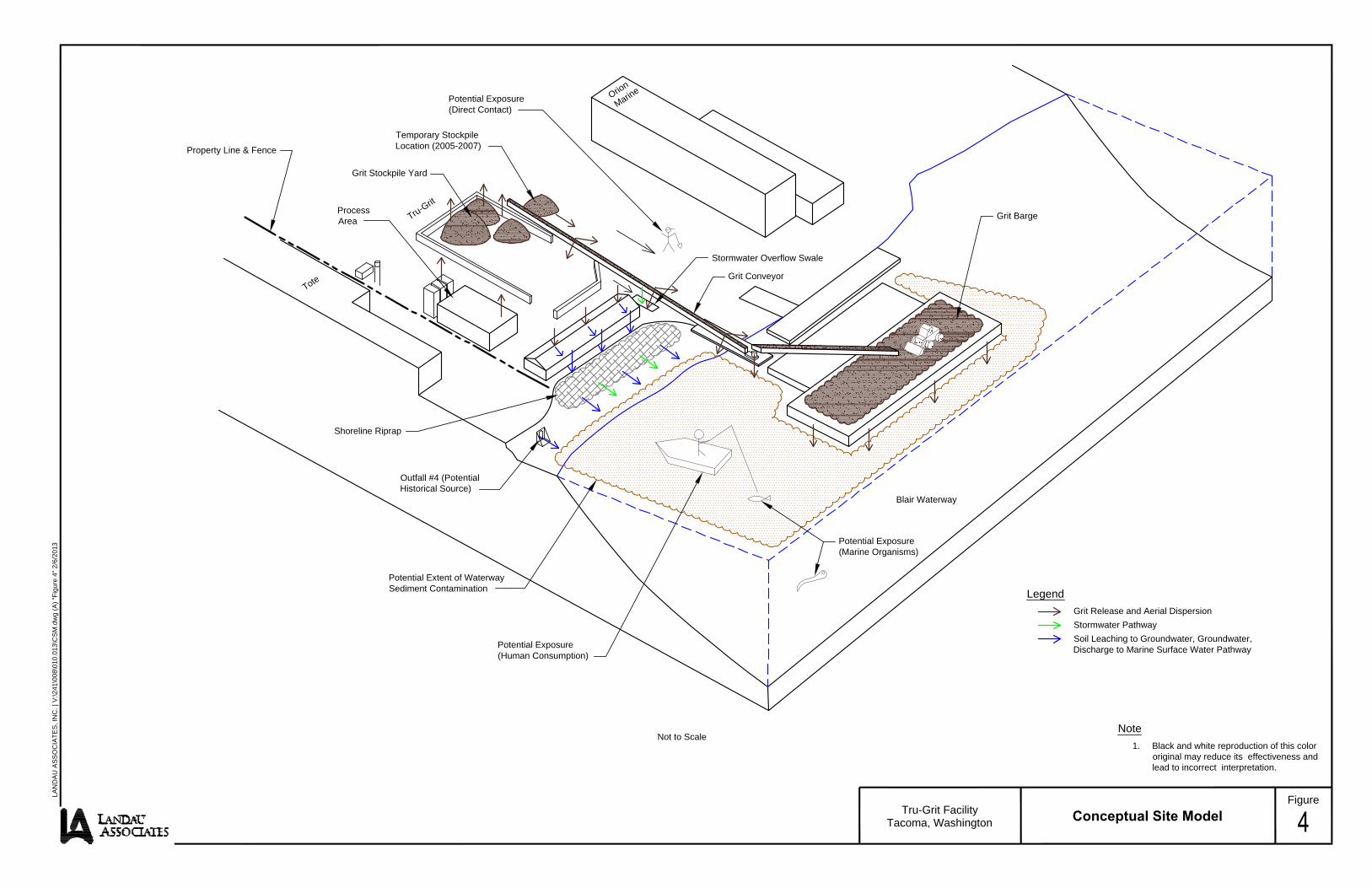
Potential Extent of WaterwaySediment Contamination
Potential Exposure(Human Consumption)
Potential Exposure(Marine Organisms)
Blair Waterway
Shoreline Riprap
Grit Conveyor
Stormwater Overflow Swale
Potential Exposure(Direct Contact)
Grit Barge
Property Line & Fence
Grit Stockpile Yard
Temporary StockpileLocation (2005-2007)
ProcessArea Tru-Grit
Tote
Orion
Marine
Outfall #4 (PotentialHistorical Source)
Tru-Grit FacilityTacoma, Washington Conceptual Site Model
FigureLAN
DA
U A
SS
OC
IATE
S, I
NC
. | V
:\241
\008
\010
.013
\CS
M.d
wg
(A) "
Figu
re 4
" 2/6
/201
3
Note1. Black and white reproduction of this color
original may reduce its effectiveness andlead to incorrect interpretation.
Not to Scale
LegendGrit Release and Aerial DispersionStormwater PathwaySoil Leaching to Groundwater, Groundwater,Discharge to Marine Surface Water Pathway

Blair Waterway
TRU-GRIT
GRAYMONT WESTERN
ORION MARINE
TOTE
Alexander Avenue
East 1
1th Stre
et
BSG-1
BSG-2
0 300 600
Scale in Feet
Source: Google Earth Pro 2010
Tru-Grit FacilityTacoma, Washington Background Sample Locations
Figure
LANDAU ASSOCIATES, INC. | V:\241\008\010.013\BkgrndSampLocs.dwg (A) "Figure 5" 2/6/2013
Note
1. Black and white reproduction of this colororiginal may reduce its effectiveness andlead to incorrect interpretation.
LegendParcel Boundary Line
Background Grab Sample Location

TABLE 1TOTAL METALS CONTENT
GRANDBY BAY SLAG AND TRU-GRIT DRY MATERIAL(a)TRU-GRIT FACILITY
TACOMA, WASHINGTON
Page 1 of 1
2/6/2013Y:\241\008\R\RI Work Plan\Tables\TruGrit EDR RI-FS_tb1 LANDAU ASSOCIATES
OCL Materials LTD11/4/1991 11/4/1991 Apr-92Tru-Grit Black Tru-Grit
Analyte 1 4 Material Lustre (b) Material
Aluminum 28,900 23,800 NA NA NA
Antimony NA NA <1.0 <1.0 NA
Arsenic <5 <5 <0.90 <0.90 <10
Barium NA NA 100 100 929
Beryllium 440 430 <0.090 <0.90 NA
Cadmium <2.5 <2.5 <0.18 <0.18 <0.1
Chromium 94.8 74.4 27 27 29.5
Chromium (+6) NA NA 0.085 0.085 NA
Chromium (+3) NA NA 27 27 NA
Cobalt NA NA 60 60 180
Copper 2,590 2,330 1,000 1,000 2,280
Iron 329,000 337,000 NA NA NA
Lead 84.7 84.3 35 35 21
Mercury <0.1 <0.1 <0.1 <0.1 <0.03
Molybdenum NA NA 27 27 7.7
Nickel NA NA 1.5 1.5 4.3
Selenium 4 2.9 <0.45 <0.45 <1
Silver <5 <5 1.4 1.4 NA
Thallium NA NA <0.72 <0.72 NA
Vanadium NA NA 37 37 NA
Zinc 8,380 8,930 3,900 3,900 8,270
Sodium NA NA 2,200 2,200 NA
NA = Not analyzed(a) = Grandby Bay stockpile is the source of all materials analyzed.(b) = Black Lustre is a Canadian trade name for Tru-Grit material.
Sample No.
Anyox slag (Tru-Grit Raw Material)British Columbia Research
Sound AnalyticalReport Date 7/91

TABLE 2LEACHATE HEAVY METAL CONTENT
TRU-GRIT FACILITYTACOMA, WASHINGTON
Page 1 of 1
2/6/2013 Y:\241\008\R\RI Work Plan\Tables\TruGrit EDR RI-FS_tb2 LANDAU ASSOCIATES
Result PQL DF EPA# Limit @ EPA Method
Arsenic (As) ND 0.01 1 D004 5.0 6010BBarium (Ba) 0.820 0.10 1 D005 100.0 6010BCadmium (Cd) ND 0.01 1 D006 1.0 6010BChromium (Cr) ND 0.01 1 D007 5.0 6010BLead (Pb) ND 0.01 1 D008 5.0 6010BMercury (Hg) ND 0.01 1 D009 0.2 7470ASelenium (Se) ND 0.10 1 D010 1.0 6010BSilver (Ag) ND 0.02 1 D011 5.0 6010B
DF=Dilution FactorPQL= Practical Quantitation LimitActual Detection Limit= PQL X DFND= Below the actual Detection Limit or non-detectedEPA#= The EPA Hazardous Waste NumberLimit@= The "EPA Acceptable Land Disposal Limit"***= The concentration exceeds the TCLP Limit (if marked)
p Maximum Level,
p Screening Level/Minimum
WAC 173-204-520 (a)
WAC 173-204-420 (a);WAC 173-204-320 (a)Sediment Quality Standards
and
TCLP-Metals Analysis (Per 40 CFR 261.24)Concentration Unit: mg/L in Leachate
mg/L= Milligram per Liter=PPMTCLP Extraction Method= EPA 1311

TABLE 3BIOASSAY DATA
TRU-GRIT FACILITYTACOMA, WASHINGTON
Page 1 of 1
2/6/2013Y:\241\008\R\RI Work Plan\Tables\TruGrit EDR RI-FS_tb3 LANDAU ASSOCIATES
Bioassay Testing Services (Tacoma)Trout Bioassay 3/90Ecology 173-303 Method 80-12
Concentration Mortality100 mg/L 0/30
1,000 mg/L 5/30
British Columbia Research*Threespined Stickleback Bioassay 4/93Saltwater Test
Concentration wt/wt % 24 hr 48 hr 72 hr 96 hr22 (a) 100 100 100 100
10 100 100 100 1004.4 100 100 100 1001 100 100 100 100
(a) Saltwater Supernatant AnalysisFrom 22% Concentration Bioassay Tank(for select metals)
Analyte ConcentrationCopper <0.05 mg/L
Chromium <5 mg/LZinc 0.02 mg/L
* Reference Toxicant for stickleback 96hLC50 phenol 17.8n and 18.7 mg/L, which compares well with rainbow trout phenol toxicity in fresh water 10-15 mg/L
% Survival

TABLE 42008 SEDIMENT INVESTIGATION RESULTS
TRU-GRIT FACILITYTACOMA, WASHINGTON
Page 1 of 1
2/6/2013Y:\241\008\R\RI Work Plan\Tables\TruGrit EDR RI-FS_tb4 LANDAU ASSOCIATES
Arsenic
G-1 G-1 End of Conveyor Pier 303 280 762 914 19.9C-1(15-25) C-1A 15-25 centimerter depth at G-1 N/A 700 N/A 1590 24.3C-1(25-35) C-1B 25-35 centimeter depth at G-1 N/A 314 N/A 957 44.7G-2 G-2 End of Conveyor Pier 117 72.4 228 180 24.9G-3 G-3 End of Conveyor Pier 221 180 296 285 55.2G-4 G-4 End of Conveyor Pier 151 140 217 200 17.5G-5 G-5 End of Conveyor Pier 1350 1390 2970 3400 8.9G-B1 G-B1 190' North of conveyor pier N/A 391 N/A 1250 7.94C-B1 (15-25) CB-1A 15-25 centimeter depth at G-B1 N/A 332 N/A 1140 11.6C-B1 (25-40) CB-1B 25-40 centmeter depth at G-B1 N/A 55.4 N/A 86 13G-B2 G-6 Background- 560' upstream on Blair Waterway 231 229 629 665 185C-B2 (10-25) C-2A 10-25 centimeter depth at G-B2 N/A 353 N/A 1120 34.5C-B2 (25-40) C2-B 25-40 centimeter depth at G-B2 N/A 1340 N/A 4210 90.5
390 390 410 410 57390 390 960 960 93
Bold = Exceedance of sediment quality standards (SQS).Box = Exceedance of cleanup level (CSL).
Sediment Quality Standards (SQS)Clean up Screening Level (CSL)
Zinc
Ecology Results
Ecology Results
Ecology Sample ID
Landau (ARI) Results
Landau Sample ID
Landau (ARI) Results
Sample Desciption
Ecology Results
Copper

TABLE 5PRELIMINARY GROUNDWATER SCREENING LEVELS
TRU-GRIT FACILITYTACOMA, WASHINGTON
Page 1 of 1
2/6/2013Y:\241\008\R\RI Work Plan\Tables\TruGrit EDR RI-FS_tb5 LANDAU ASSOCIATES
MTCA Method B (a)
Metals (µg/L)Copper 3.1 (b) 3.1 (b) 2.4 -- -- 2,900 2 2.4Zinc 81 (b) 81 (b) 81 (b) 26,000 -- 17000 10 81
Shaded cell indicates basis for proposed screening level."---" = Indicates no criterion is available.
Notes:(a) Unless otherwise noted, all federal and state ARARs and MTCA C Cleanup Screening Levels for surface water were identified from Ecology's online CLARC database (Ecology website 2012b).(b) The surface water criterion is based on the dissolved fraction.(c) The PQL is based on Analytical Resource Inc. laboratory's limit of quantitation for EPA Method 6010C (October 2, 2012)(d) Proposed screening level is based on lowest water quality standard indicated by shading.
NTR = National Toxics Rule ARAR = Applicable or Relevant and Appropriate RequirementsWQS = Water Quality Standard CLARC = Cleanup Screening Levels and Risk CalculationMTCA = Model Toxics Control Act
State and Federal ARARs (a)
Practical Quantitation
Limit (PQL)(c)
FederalHuman HealthConsumptionof Organisms
NTR40 CFR 131
Human Health MTCA Method B Surface Water
Equation 173-340-730
(Non-Carcinogen)
ProposedPreliminary ScreeningLevel (d)Constituents
StateMarine Chronic
Aquatic LifeWashington
WQSWAC 173-201A
FederalMarine Chronic
Aquatic LifeClean Water
ActSection 304
FederalMarineChronic
Aquatic LifeNTR
40 CFR 131
FederalHuman HealthConsumptionof Organisms
Clean Water ActSection 304

TABLE 6PRELIMINARY SOIL SCREENING LEVELS
TRU-GRIT FACILITYTACOMA, WASHINGTON
Page 1 of 1
2/6/2013Y:\241\008\R\RI Work Plan\Tables\TruGrit EDR RI-FS_tb6 LANDAU ASSOCIATES
Metals (mg/kg)Copper 2.4 140,000 1.1 0.2 36Zinc 81 1,100,000 101 1.0 101
Shaded cell indicates basis for proposed screening level.
Notes:(a) Calculated using fixed parameter three-phase partitioning model, WAC 173-340-747(4) and the preliminary groundwater cleanup level shown in column 2.(b) From Ecology's Natural Background Soil Metals Concentrations in Puget Sound (Ecology 1994). Used 90th percentile for Puget Sound unless noted otherwise.(c) The PQL is based on Analytical Resource Inc. laboratory'S limit of quantitation for EPA Method 6010C (October 2, 2012)
MTCA Method C Soil Direct Contact Industrial
Land Use Non-CarcinogenConstituents
MTCA Method CProtective of
Groundwater asSurface Water (a)
SoilBackground
Levels (b)
Practical Quantitation
Limit (PQL) (c)
Preliminary Groundwater
Cleanup Level Used in Three-Phase
Model (µg/L)
8536
ProposedPreliminary
Screening Level
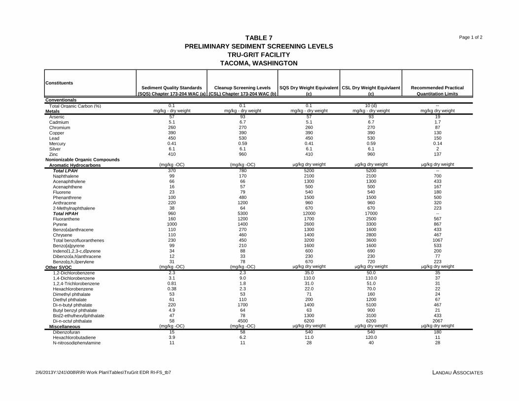
TABLE 7PRELIMINARY SEDIMENT SCREENING LEVELS
TRU-GRIT FACILITYTACOMA, WASHINGTON
Page 1 of 2
2/6/2013Y:\241\008\R\RI Work Plan\Tables\TruGrit EDR RI-FS_tb7 LANDAU ASSOCIATES
Conventionals Total Organic Carbon (%) 0.1 0.1 0.1 10 (d) --Metals mg/kg - dry weight mg/kg - dry weight mg/kg - dry weight mg/kg - dry weight mg/kg dry weight Arsenic 57 93 57 93 19 Cadmium 5.1 6.7 5.1 6.7 1.7 Chromium 260 270 260 270 87 Copper 390 390 390 390 130 Lead 450 530 450 530 150 Mercury 0.41 0.59 0.41 0.59 0.14 Silver 6.1 6.1 6.1 6.1 2 Zinc 410 960 410 960 137Nonionizable Organic Compounds Aromatic Hydrocarbons (mg/kg -OC) (mg/kg -OC) µg/kg dry weight µg/kg dry weight µg/kg dry weight Total LPAH 370 780 5200 5200 -- Naphthalene 99 170 2100 2100 700 Acenaphthylene 66 66 1300 1300 433 Acenaphthene 16 57 500 500 167 Fluorene 23 79 540 540 180 Phenanthrene 100 480 1500 1500 500 Anthracene 220 1200 960 960 320 2-Methylnaphthalene 38 64 670 670 223 Total HPAH 960 5300 12000 17000 -- Fluoranthene 160 1200 1700 2500 567 Pyrene 1000 1400 2600 3300 867 Benzo[a]anthracene 110 270 1300 1600 433 Chrysene 110 460 1400 2800 467 Total benzofluoranthenes 230 450 3200 3600 1067 Benzo[a]pyrene 99 210 1600 1600 533 Indeno[1,2,3-c,d]pyrene 34 88 600 690 200 Dibenzo[a,h]anthracene 12 33 230 230 77 Benzo[g,h,i]perylene 31 78 670 720 223Other SVOC (mg/kg -OC) (mg/kg -OC) µg/kg dry weight µg/kg dry weight µg/kg dry weight 1,2-Dichlorobenzene 2.3 2.3 35.0 50.0 35 1,4-Dichlorobenzene 3.1 9.0 110.0 110.0 37 1,2,4-Trichlorobenzene 0.81 1.8 31.0 51.0 31 Hexachlorobenzene 0.38 2.3 22.0 70.0 22 Dimethyl phthalate 53 53 71 160 24 Diethyl phthalate 61 110 200 1200 67 Di-n-butyl phthalate 220 1700 1400 5100 467 Butyl benzyl phthalate 4.9 64 63 900 21 Bis[2-ethylhexyl]phthalate 47 78 1300 3100 433 Di-n-octyl phthalate 58 4500 6200 6200 2067 Miscellaneous (mg/kg -OC) (mg/kg -OC) µg/kg dry weight µg/kg dry weight µg/kg dry weight Dibenzofuran 15 58 540 540 180 Hexachlorobutadiene 3.9 6.2 11.0 120.0 11 N-nitrosodiphenylamine 11 11 28 40 28
Cleanup Screening Levels (CSL) Chapter 173-204 WAC (b)
ConstituentsRecommended Practical
Quantitation LimitsSediment Quality Standards
(SQS) Chapter 173-204 WAC (a)SQS Dry Weight Equivalent
(c) CSL Dry Weight Equivlaent
(c)
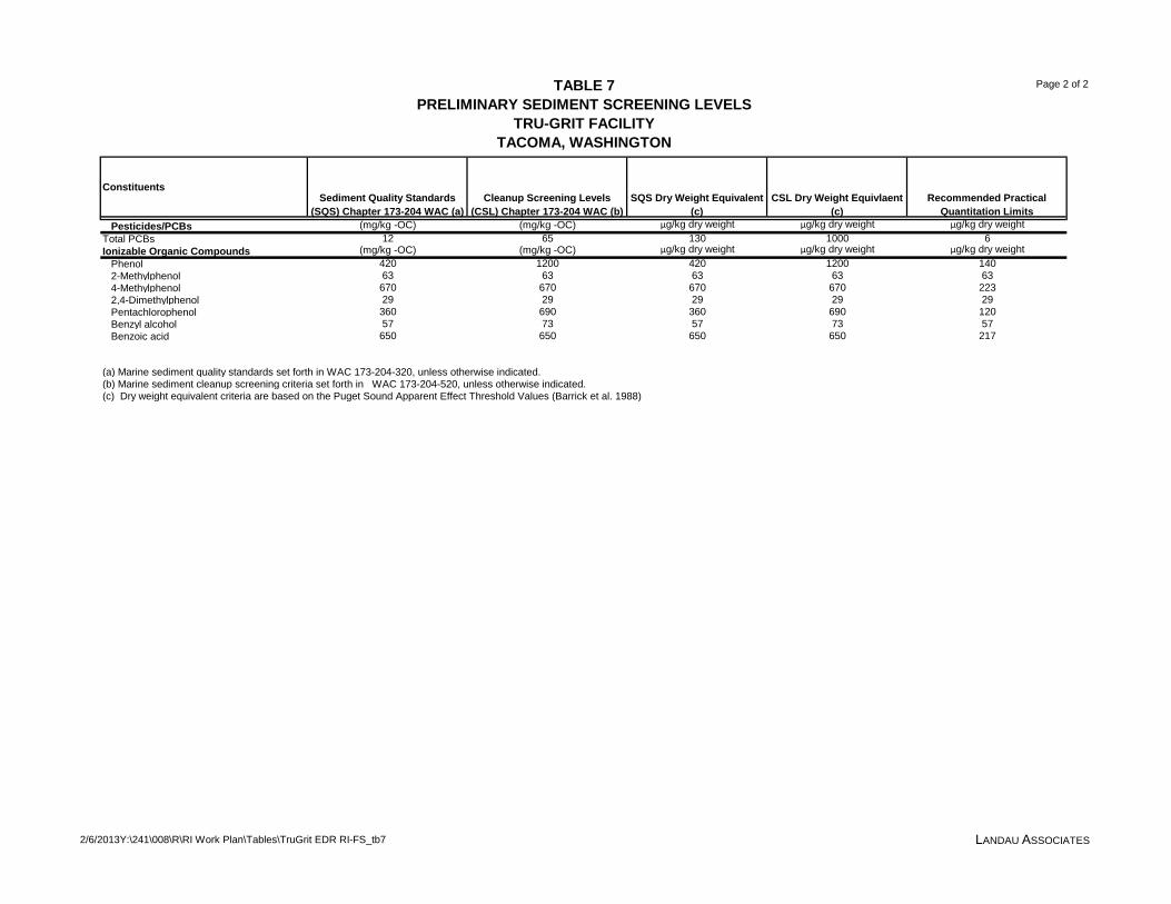
TABLE 7PRELIMINARY SEDIMENT SCREENING LEVELS
TRU-GRIT FACILITYTACOMA, WASHINGTON
Page 2 of 2
2/6/2013Y:\241\008\R\RI Work Plan\Tables\TruGrit EDR RI-FS_tb7 LANDAU ASSOCIATES
Cleanup Screening Levels (CSL) Chapter 173-204 WAC (b)
ConstituentsRecommended Practical
Quantitation LimitsSediment Quality Standards
(SQS) Chapter 173-204 WAC (a)SQS Dry Weight Equivalent
(c) CSL Dry Weight Equivlaent
(c) Pesticides/PCBs (mg/kg -OC) (mg/kg -OC) µg/kg dry weight µg/kg dry weight µg/kg dry weightTotal PCBs 12 65 130 1000 6Ionizable Organic Compounds (mg/kg -OC) (mg/kg -OC) µg/kg dry weight µg/kg dry weight µg/kg dry weight Phenol 420 1200 420 1200 140 2-Methylphenol 63 63 63 63 63 4-Methylphenol 670 670 670 670 223 2,4-Dimethylphenol 29 29 29 29 29 Pentachlorophenol 360 690 360 690 120 Benzyl alcohol 57 73 57 73 57 Benzoic acid 650 650 650 650 217
(a) Marine sediment quality standards set forth in WAC 173-204-320, unless otherwise indicated.(b) Marine sediment cleanup screening criteria set forth in WAC 173-204-520, unless otherwise indicated.(c) Dry weight equivalent criteria are based on the Puget Sound Apparent Effect Threshold Values (Barrick et al. 1988)

APPENDIX A
Sampling and Analysis Plan

950 Pacific Avenue, Suite 515 Tacoma, WA 98402
(253) 926-2493
February 6, 2013
Prepared for
CanAm Minerals, Inc. Tacoma, Washington
Sampling and Analysis Plan Remedial Investigation / Feasibility Study
Work Plan Tru-Grit Facility
Tacoma, Washington
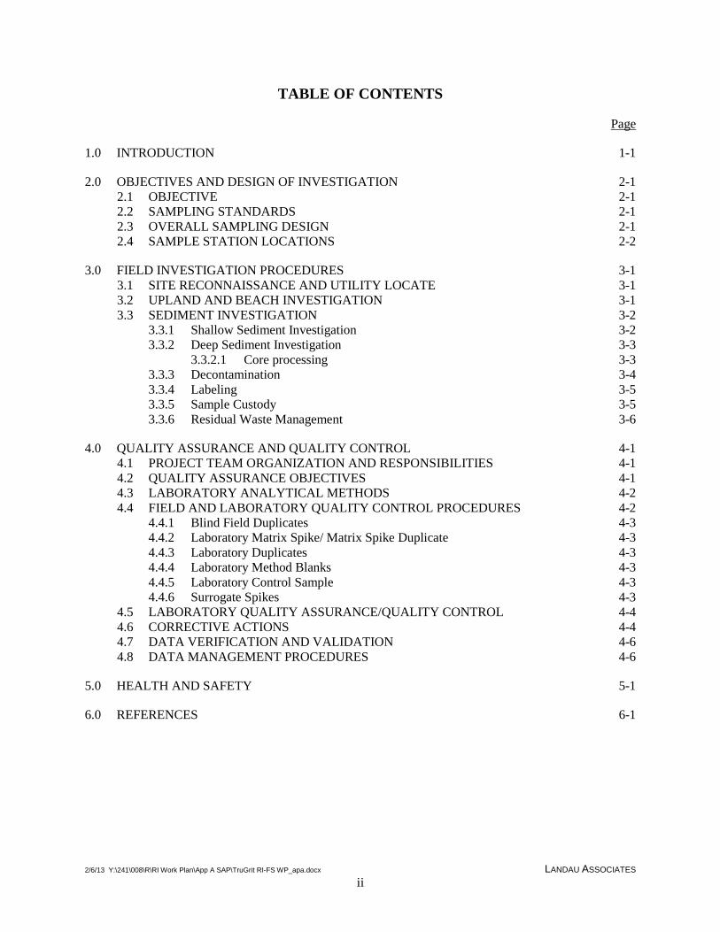
2/6/13 Y:\241\008\R\RI Work Plan\App A SAP\TruGrit RI-FS WP_apa.docx LANDAU ASSOCIATES ii
TABLE OF CONTENTS
Page
1.0 INTRODUCTION 1-1
2.0 OBJECTIVES AND DESIGN OF INVESTIGATION 2-1 2.1 OBJECTIVE 2-1 2.2 SAMPLING STANDARDS 2-1 2.3 OVERALL SAMPLING DESIGN 2-1 2.4 SAMPLE STATION LOCATIONS 2-2
3.0 FIELD INVESTIGATION PROCEDURES 3-1 3.1 SITE RECONNAISSANCE AND UTILITY LOCATE 3-1 3.2 UPLAND AND BEACH INVESTIGATION 3-1 3.3 SEDIMENT INVESTIGATION 3-2
3.3.1 Shallow Sediment Investigation 3-2 3.3.2 Deep Sediment Investigation 3-3
3.3.2.1 Core processing 3-3 3.3.3 Decontamination 3-4 3.3.4 Labeling 3-5 3.3.5 Sample Custody 3-5 3.3.6 Residual Waste Management 3-6
4.0 QUALITY ASSURANCE AND QUALITY CONTROL 4-1 4.1 PROJECT TEAM ORGANIZATION AND RESPONSIBILITIES 4-1 4.2 QUALITY ASSURANCE OBJECTIVES 4-1 4.3 LABORATORY ANALYTICAL METHODS 4-2 4.4 FIELD AND LABORATORY QUALITY CONTROL PROCEDURES 4-2
4.4.1 Blind Field Duplicates 4-3 4.4.2 Laboratory Matrix Spike/ Matrix Spike Duplicate 4-3 4.4.3 Laboratory Duplicates 4-3 4.4.4 Laboratory Method Blanks 4-3 4.4.5 Laboratory Control Sample 4-3 4.4.6 Surrogate Spikes 4-3
4.5 LABORATORY QUALITY ASSURANCE/QUALITY CONTROL 4-4 4.6 CORRECTIVE ACTIONS 4-4 4.7 DATA VERIFICATION AND VALIDATION 4-6 4.8 DATA MANAGEMENT PROCEDURES 4-6
5.0 HEALTH AND SAFETY 5-1
6.0 REFERENCES 6-1

2/6/13 Y:\241\008\R\RI Work Plan\App A SAP\TruGrit RI-FS WP_apa.docx LANDAU ASSOCIATES iii
FIGURES
Figure Title
A-1 Proposed Sampling Locations A-2 Background Sample Locations
TABLES
Table Title
A-1 Sediment Sample Locations and Elevations A-2 Sample Size, Containers, and Analytical Methods A-3 Recommended Sample Preparation Methods, Cleanup Methods, Analytical Methods, and
Practical Quantitation Limits for Sediments A-4 Quantitation Limit Goals for Soil and Groundwater A-5 Laboratory QC Sample Acceptance Criteria – Sediment A-6 Laboratory QC Sample Acceptance Criteria – Soil and Water
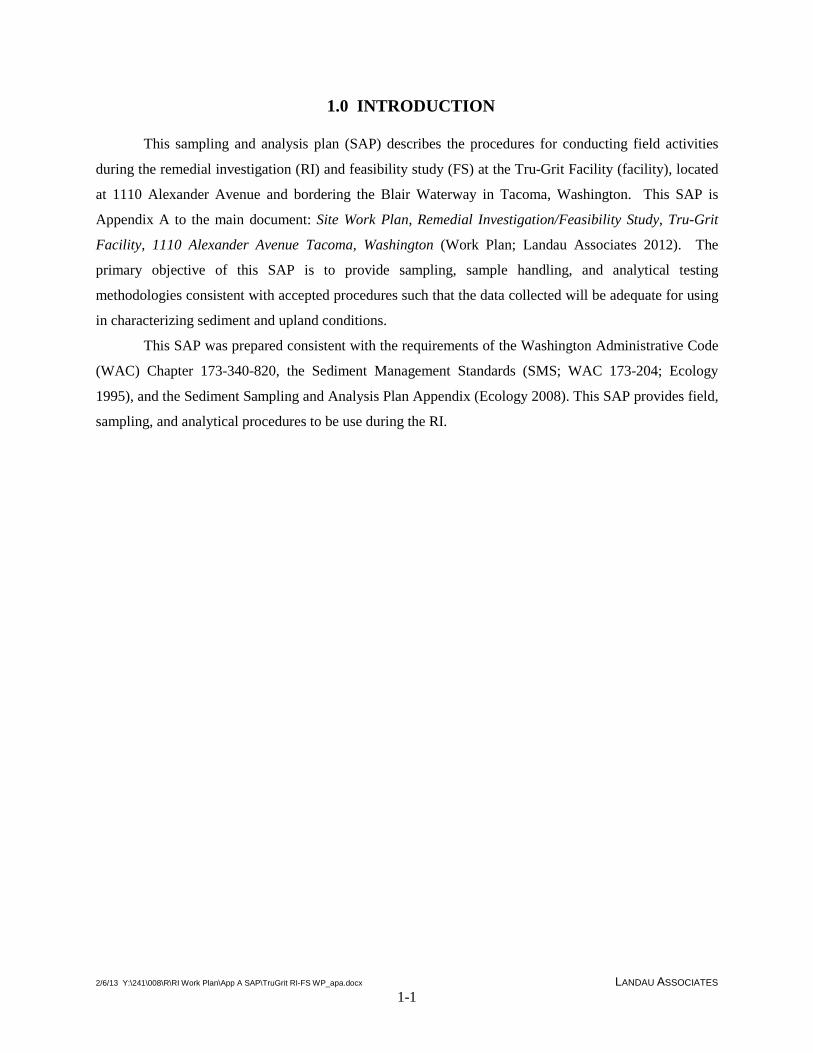
2/6/13 Y:\241\008\R\RI Work Plan\App A SAP\TruGrit RI-FS WP_apa.docx LANDAU ASSOCIATES 1-1
1.0 INTRODUCTION
This sampling and analysis plan (SAP) describes the procedures for conducting field activities
during the remedial investigation (RI) and feasibility study (FS) at the Tru-Grit Facility (facility), located
at 1110 Alexander Avenue and bordering the Blair Waterway in Tacoma, Washington. This SAP is
Appendix A to the main document: Site Work Plan, Remedial Investigation/Feasibility Study, Tru-Grit
Facility, 1110 Alexander Avenue Tacoma, Washington (Work Plan; Landau Associates 2012). The
primary objective of this SAP is to provide sampling, sample handling, and analytical testing
methodologies consistent with accepted procedures such that the data collected will be adequate for using
in characterizing sediment and upland conditions.
This SAP was prepared consistent with the requirements of the Washington Administrative Code
(WAC) Chapter 173-340-820, the Sediment Management Standards (SMS; WAC 173-204; Ecology
1995), and the Sediment Sampling and Analysis Plan Appendix (Ecology 2008). This SAP provides field,
sampling, and analytical procedures to be use during the RI.

2/6/13 Y:\241\008\R\RI Work Plan\App A SAP\TruGrit RI-FS WP_apa.docx LANDAU ASSOCIATES 2-1
2.0 OBJECTIVES AND DESIGN OF INVESTIGATION
This section establishes the objectives of the sediment and upland investigation, gives a brief
overview of the design of the investigation, and provides an explanation of chemical analyses that will be
performed as part of this investigation.
2.1 OBJECTIVE As noted in Section 1.0, the goal of the RI is to determine the lateral and vertical extent of
contamination at the facility and to determine if there are ongoing sources of sediment contamination in
upland areas. This information will be used to develop, evaluate, and select appropriate cleanup actions in
the FS.
2.2 SAMPLING STANDARDS Sampling will be undertaken to address the analytical requirements set forth in the SMS (WAC
173-204). The current Washington State Department of Ecology (Ecology) guidance document Sediment
Sampling and Analysis Plan Appendix (Ecology 2008) was used to develop this SAP and to ensure that
SMS requirements are achieved. To address the SMS requirements, a subset of the sediment samples
collected during this investigation will be analyzed for the full suite of 47 SMS chemicals and the
additional conventional sediment variables. The remaining sediment and soil samples will be analyzed for
copper, zinc, and arsenic to delineate the lateral and vertical extent of contamination.
Sediment sample results are compared against two sets of criteria. The marine sediment quality
standard (SQS; WAC 173-204-320) and the sediment cleanup screening level criteria (CSL; WAC 173-
204-520). The SQS is the concentration below which effects to biological resources and human health
are unlikely, where as the CSL is the concentration above which more than minor adverse biological
effects may be expected. Sediment criteria are presented in Table 7 of the Work Plan.
Upland soil samples will be compared against preliminary screening levels (PSLs) presented in
Table 6 of the work plan. PSLs were developed in accordance with MTCA (WAC 173-340).
2.3 OVERALL SAMPLING DESIGN As noted in the Work Plan, previous investigation at the facility determined that the area directly
under and near the ship-to-shore conveyance system at the Tru-Grit facility contained raw grit material
(Landau 2009). At the southwestern end of the ship-to-shore conveyance system, the grit material was
present in a sufficient quantity to increase the copper and zinc concentrations in the sediment to levels
above the CSL in one location (G-5). Results of the previous investigation were indicative of localized

2/6/13 Y:\241\008\R\RI Work Plan\App A SAP\TruGrit RI-FS WP_apa.docx LANDAU ASSOCIATES 2-2
impacts at the site resulting from release of grit material to the waterway but also of area-wide impact to
sediment from past industrial operations at multiple facilities. Although arsenic is not a contaminant of
concern at the site, sampling for arsenic will be conducted to differentiate site contamination from area-wide
impacts. In accordance with the results of the previous investigation, as well as the main goal of the current
RI, the following three areas of concern have been identified:
• The upland area
• The intertidal (beach) area
• The subtidal waterway.
2.4 SAMPLE STATION LOCATIONS Sampling locations are shown on Figure A-1 and A-2, and include 5 upland area soil samples, 4
beach sediment samples, and 20 sediment grab samples and cores in the subtidal waterway (including
background samples). Sample locations were chosen based on information from the previous sediment
investigation and possible contaminant sources and pathways.
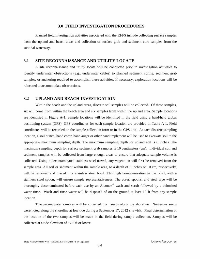
2/6/13 Y:\241\008\R\RI Work Plan\App A SAP\TruGrit RI-FS WP_apa.docx LANDAU ASSOCIATES 3-1
3.0 FIELD INVESTIGATION PROCEDURES
Planned field investigation activities associated with the RI/FS include collecting surface samples
from the upland and beach areas and collection of surface grab and sediment core samples from the
subtidal waterway.
3.1 SITE RECONNAISSANCE AND UTILITY LOCATE A site reconnaissance and utility locate will be conducted prior to investigation activities to
identify underwater obstructions (e.g., underwater cables) to planned sediment coring, sediment grab
samples, or anchoring required to accomplish these activities. If necessary, exploration locations will be
relocated to accommodate obstructions.
3.2 UPLAND AND BEACH INVESTIGATION Within the beach and the upland areas, discrete soil samples will be collected. Of these samples,
six will come from within the beach area and six samples from within the upland area. Sample locations
are identified in Figure A-1. Sample locations will be identified in the field using a hand-held global
positioning system (GPS); GPS coordinates for each sample location are provided in Table A-1. Field
coordinates will be recorded on the sample collection form or in the GPS unit. At each discrete sampling
location, a soil punch, hand corer, hand auger or other hand implement will be used to excavate soil to the
appropriate maximum sampling depth. The maximum sampling depth for upland soil is 6 inches. The
maximum sampling depth for surface sediment grab samples is 10 centimeters (cm). Individual soil and
sediment samples will be collected from large enough areas to ensure that adequate sample volume is
collected. Using a decontaminated stainless steel trowel, any vegetation will first be removed from the
sample area. All soil or sediment within the sample area, to a depth of 6 inches or 10 cm, respectively,
will be removed and placed in a stainless steel bowl. Thorough homogenization in the bowl, with a
stainless steel spoon, will ensure sample representativeness. The corer, spoons, and steel tape will be
thoroughly decontaminated before each use by an Alconox® wash and scrub followed by a deionized
water rinse. Wash and rinse water will be disposed of on the ground at least 10 ft from any sample
location.
Two groundwater samples will be collected from seeps along the shoreline. Numerous seeps
were noted along the shoreline at low tide during a September 17, 2012 site visit. Final determination of
the location of the two samples will be made in the field during sample collection. Samples will be
collected at a tide elevation of +2.5 ft or lower.
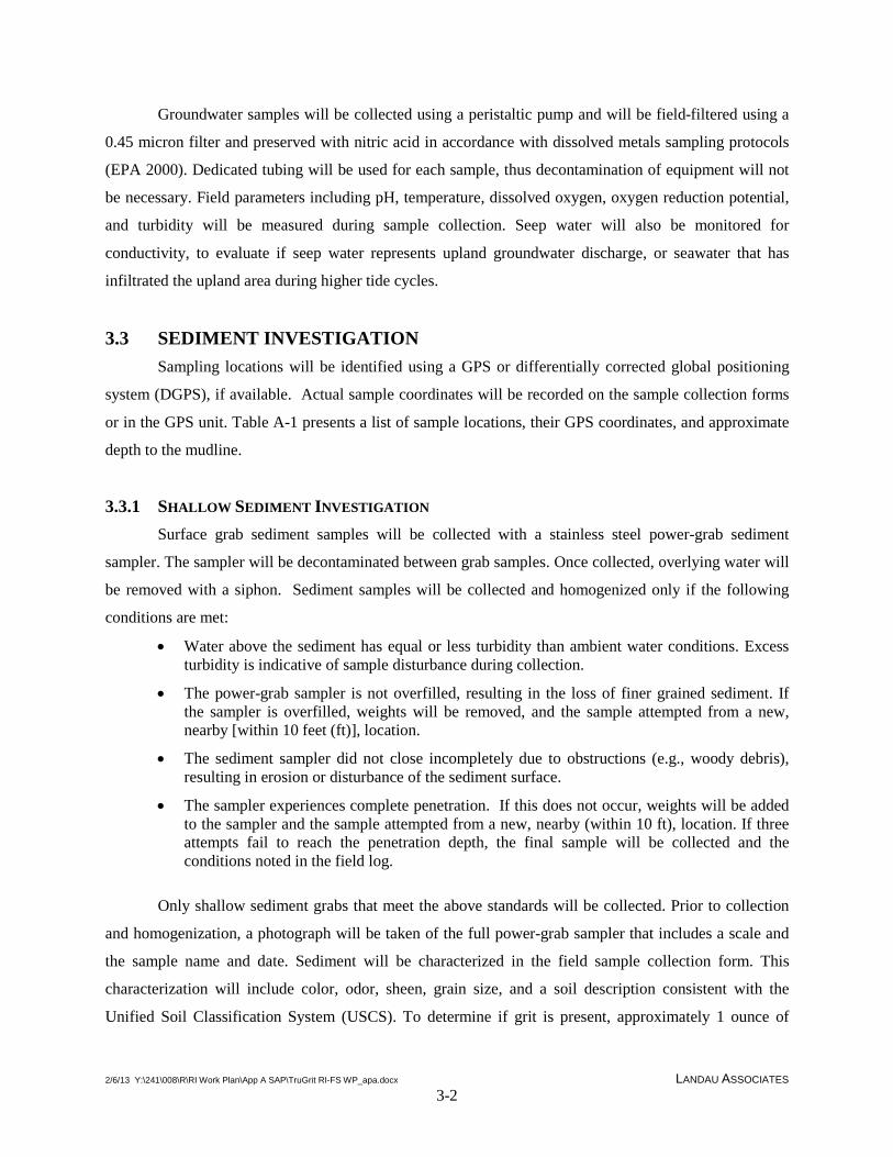
2/6/13 Y:\241\008\R\RI Work Plan\App A SAP\TruGrit RI-FS WP_apa.docx LANDAU ASSOCIATES 3-2
Groundwater samples will be collected using a peristaltic pump and will be field-filtered using a
0.45 micron filter and preserved with nitric acid in accordance with dissolved metals sampling protocols
(EPA 2000). Dedicated tubing will be used for each sample, thus decontamination of equipment will not
be necessary. Field parameters including pH, temperature, dissolved oxygen, oxygen reduction potential,
and turbidity will be measured during sample collection. Seep water will also be monitored for
conductivity, to evaluate if seep water represents upland groundwater discharge, or seawater that has
infiltrated the upland area during higher tide cycles.
3.3 SEDIMENT INVESTIGATION Sampling locations will be identified using a GPS or differentially corrected global positioning
system (DGPS), if available. Actual sample coordinates will be recorded on the sample collection forms
or in the GPS unit. Table A-1 presents a list of sample locations, their GPS coordinates, and approximate
depth to the mudline.
3.3.1 SHALLOW SEDIMENT INVESTIGATION Surface grab sediment samples will be collected with a stainless steel power-grab sediment
sampler. The sampler will be decontaminated between grab samples. Once collected, overlying water will
be removed with a siphon. Sediment samples will be collected and homogenized only if the following
conditions are met:
• Water above the sediment has equal or less turbidity than ambient water conditions. Excess turbidity is indicative of sample disturbance during collection.
• The power-grab sampler is not overfilled, resulting in the loss of finer grained sediment. If the sampler is overfilled, weights will be removed, and the sample attempted from a new, nearby [within 10 feet (ft)], location.
• The sediment sampler did not close incompletely due to obstructions (e.g., woody debris), resulting in erosion or disturbance of the sediment surface.
• The sampler experiences complete penetration. If this does not occur, weights will be added to the sampler and the sample attempted from a new, nearby (within 10 ft), location. If three attempts fail to reach the penetration depth, the final sample will be collected and the conditions noted in the field log.
Only shallow sediment grabs that meet the above standards will be collected. Prior to collection
and homogenization, a photograph will be taken of the full power-grab sampler that includes a scale and
the sample name and date. Sediment will be characterized in the field sample collection form. This
characterization will include color, odor, sheen, grain size, and a soil description consistent with the
Unified Soil Classification System (USCS). To determine if grit is present, approximately 1 ounce of

2/6/13 Y:\241\008\R\RI Work Plan\App A SAP\TruGrit RI-FS WP_apa.docx LANDAU ASSOCIATES 3-3
sediment will be rinsed through an ASTM International No. 200 sieve to remove fines. Because grit
material is processed to remove significant fines prior to transport by barge to the Tru-Grit facility, further
sieving is unlikely to remove significant grit material. Sediment remaining in the sieve after rinsing will
be placed under a microscope or hand lens for identification of grit material within the sample.
Sediment will be collected from the benthic zone (top 10 cm of the sediment) from an area large
enough to ensure adequate sample volume and excluding portions that are touching the power-grab
sampler. This collected sediment will exclude large, unrepresentative material (e.g., shells, woody debris).
Sediment will be homogenized in decontaminated stainless steel bowls, using a decontaminated stainless
steel spoon. After sufficient homogenization, sediment will be placed into laboratory supplied containers
and placed on ice. Unused sediment will be contained for later disposal.
3.3.2 DEEP SEDIMENT INVESTIGATION Deeper sediments will be collected using vibrocore sediment coring methods, using the following
steps:
• Actual tide level will be confirmed at a surveyed location on or near the site at least three times during the sampling day, and compared to listed tides. If these are in exact agreement throughout the first day, this step can be eliminated during later sampling.
• Water depth will be measured using a weighted line.
• The actual mudline at the sample location will be calculated (this may be slightly different than the expected mudline at the sample location based on mapped bathymetry).
• A minimum penetration depth of 100 cm (~3.3 ft) will be achieved.
• Collected cores will be allowed to settle until the overlying water is almost clear and the recovery length will be measured.
• Cores that have over 75 percent recovery length will be saved and numerically decompacted during processing.
• Cores that have under 75 percent recovery length will be returned to the collection site and a new core will be collected in the nearby (within 10 ft) vicinity. If refusal is encountered prior to full penetration, the vibrocore will be repositioned and a new core will be attempted. If refusal is met during the third such attempt, this core will be collected and noted in the field log.
• Cores will be drained of overlying water, capped, and labeled with the sample number, date, and surface direction. Cores will be stored on ice overnight in a secure location, or will be transported to the lab for storage each night.
3.3.2.1 Core processing
Core processing will be accomplished at the laboratory, after sample collection is complete.
Length intervals to be sampled are discussed in Section 6.5of the work plan. Core processing will be
accomplished using the following steps:

2/6/13 Y:\241\008\R\RI Work Plan\App A SAP\TruGrit RI-FS WP_apa.docx LANDAU ASSOCIATES 3-4
• Care will be taken to avoid spills and plastic sheeting will cover all laboratory surfaces during processing.
• Cores will be cut open lengthwise using sheet metal sheers, leaving the caps on the core to maintain core-tube integrity.
• The outer sediment surface (that was touching the liner) will be removed with a decontaminated stainless steel spoon and disposed of.
• The core will be split in half lengthwise, using a decontaminated stainless steel spatula.
• All interval measurements will be adjusted according to the percent retention (length of sediment sample retrieved/penetration depth of core tube) of the sediment collected within each individual core tube. For example, if 6 ft of sediment were retrieved from a core with a penetration depth of 8 ft, the retention ratio was 0.75 or 75 percent. The resulting intervals to be sampled would then be adjusted for 75 percent sediment retention.
• A photograph will be taken of the individual sediment layers that include the sample name, the layer depth range, processing date and original surface direction.
• Sediment will be characterized in the sample collection form. This characterization will include color, odor, grain size, and a soil description consistent with the USCS. This description will also include any oil sheen, biological activity (e.g., shells, worms, etc.), debris, or other distinguishing features and the depth at which these occur.
• Sediment will be collected from each individual layer, excluding sediment portions that are touching core walls, and homogenized in decontaminated stainless steel bowls using a decontaminated stainless steel spoon.
• An aliquot of sample from each layer will be placed under a microscope and examined for the presence of grit. The approximate percentage of grit in the sample will be noted in the field log. As needed, magnified photographs of the sediment may be taken to document the presence or absence of grit material.
• After sufficient homogenization, sediment will be placed into laboratory supplied containers and placed on ice. Enough volume (0.5 inch headspace) will be left in archived sample containers to accommodate expansion of the sample during freezing.
3.3.3 DECONTAMINATION All field sampling equipment, including vibrocore heads, stainless steel bowls and spoons, and
sample core tubes will be decontaminated in the following manner:
• Rinsed with clean site water
• Scrubbed with Alconox
• Rinsed with clean site water.
Equipment used during core processing at the laboratory will be rinsed with clean tap water
initially, and the final rinse will be with de-ionized water.

2/6/13 Y:\241\008\R\RI Work Plan\App A SAP\TruGrit RI-FS WP_apa.docx LANDAU ASSOCIATES 3-5
3.3.4 LABELING Sample identification will adhere to the following format: Sampling Type and location (e.g., U-1
for upland samples, SG-1 for sediment grab or BSG-1 for background sediment grab, SC-1 for sediment
core, respectively), followed by the depth range for core samples [e.g., SC-1(2-3) for core sample one
from a depth of between 2 and 3 ft).
3.3.5 SAMPLE CUSTODY The primary objective of sample custody is to create an accurate, written record that can be used
to trace the possession and handling of samples so that their quality and integrity can be maintained from
collection until completion of all required analyses. Adequate sample custody will be achieved by means
of approved field and analytical documentation. Such documentation includes the chain-of-custody
record that is initially completed by the sampler and is, thereafter, signed by those individuals who accept
custody of the sample. A sample is in custody if at least one of the following is true:
• It is in someone’s physical possession
• It is in someone’s view
• It is secured in a locked container or otherwise sealed so that tampering will be evident
• It is kept in a secured area, restricted to authorized personnel only.
Sample control and chain-of-custody in the field and during transportation to the laboratory will
be conducted in general conformance with the procedures described below:
• As few persons as possible will handle samples.
• Sample bottles will be obtained new or pre-cleaned from the laboratory performing the analyses.
• The sample collector will be personally responsible for the completion of the chain-of-custody record and the care and custody of samples collected until they are transferred to another person or dispatched properly under chain-of-custody rules.
• The coolers in which the samples are transported will be accompanied by the chain-of-custody record identifying their contents. The original record and laboratory copy will accompany the shipment. The other copy will be forwarded to Landau Associates along with sample collection forms.
When samples are transferred, the individuals relinquishing and receiving the samples will sign
the chain-of-custody form in the appropriate space and record the date and time of transfer.
A designated sample custodian at the laboratory will accept custody of the samples and certify
that the sample identification numbers match those on the chain-of-custody record. The custodian will
then enter sample identification number data into a log that will be maintained by the laboratory.

2/6/13 Y:\241\008\R\RI Work Plan\App A SAP\TruGrit RI-FS WP_apa.docx LANDAU ASSOCIATES 3-6
All documentation and other project records will be safeguarded to prevent loss, damage, or
alteration. If an error is made on a document, corrections will be made by drawing a single line through
the error and entering the correct information. The erroneous information will not be obliterated.
Corrections will be initialed and dated and, if necessary, a footnote explaining the correction will be
included. Errors will be corrected by the person who made the entry, whenever possible.
3.3.6 RESIDUAL WASTE MANAGEMENT
Contaminated sediments that are not immediately returned to the site location will be disposed in
55-gallon drums at a designated site, awaiting analytical results. Each drum will be labeled identifying the
contents and the approximate extent that the drum is filled, the accumulation start date, and the
explorations from which the sediment was generated. The client will assume responsibility of disposing
of site waste appropriately.

2/6/13 Y:\241\008\R\RI Work Plan\App A SAP\TruGrit RI-FS WP_apa.docx LANDAU ASSOCIATES 4-1
4.0 QUALITY ASSURANCE AND QUALITY CONTROL
This section describes the quality assurance/quality control (QA/QC) procedures in support of the
RI at the Tru-Grit facility. This section will establish the project team organization and responsibilities,
the quality assurance objectives, laboratory analytical methods, QA/QC requirements and corrective
actions for this project.
4.1 PROJECT TEAM ORGANIZATION AND RESPONSIBILITIES The project team organizational structure was developed based on the requirements of the field
and laboratory activities. The key positions/contractors and associated responsibilities are described
below:
• Consultant Project Manager: Responsible for implementation of all aspects of the project plans. Specific responsibilities include review and approval of revisions to RI documentation, overseeing that all technical procedures are followed, reporting of deviations from the Ecology-approved project plans to the Ecology project coordinator and overseeing that data collected will satisfy the quality assurance objectives.
• Ecology Project Coordinator: Responsible for overseeing implementation of all aspects of the project plans. Specific responsibilities include review and approval of revisions to RI documentation, overseeing that all technical procedures are followed, and overseeing that data collected will satisfy the quality assurance objectives.
• Analytical Laboratory: Responsible for providing sample bottles, performing chemical analyses per the SAP and reporting of data as required by the SAP.
• Field Sampling Personnel: Responsible for implementing sampling procedures as specified in the project plans, notifying the consultant project manager of any deviations from the project plans.
4.2 QUALITY ASSURANCE OBJECTIVES The Quality Assurance (QA) objectives for this project are to develop and implement procedures
that will ensure collection of representative data of known, acceptable, and defensible quality. The data
quality parameters used to assess the acceptability of the data are representativeness, comparability,
precision, accuracy, bias, and completeness.
• Representativeness expresses the degree to which data accurately and precisely represent an actual condition or characteristic of a population. Representativeness can be achieved by selecting appropriate sampling locations and by using appropriate sampling methods.
• Comparability expresses the confidence with which one data set can be evaluated in relation to another data set. For this work, comparability of data will be established through the use of standard analytical methodologies with analytical limits of quantitation (LOQs) that can meet screening level criteria to the extent practicable and by utilizing standard reporting formats.
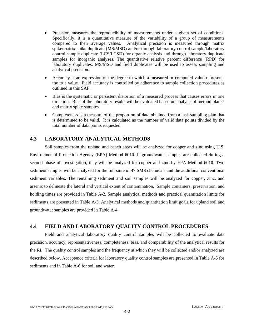
2/6/13 Y:\241\008\R\RI Work Plan\App A SAP\TruGrit RI-FS WP_apa.docx LANDAU ASSOCIATES 4-2
• Precision measures the reproducibility of measurements under a given set of conditions. Specifically, it is a quantitative measure of the variability of a group of measurements compared to their average values. Analytical precision is measured through matrix spike/matrix spike duplicate (MS/MSD) and/or through laboratory control sample/laboratory control sample duplicate (LCS/LCSD) for organic analysis and through laboratory duplicate samples for inorganic analyses. The quantitative relative percent difference (RPD) for laboratory duplicates, MS/MSD and field duplicates will be used to assess sampling and analytical precision.
• Accuracy is an expression of the degree to which a measured or computed value represents the true value. Field accuracy is controlled by adherence to sample collection procedures as outlined in this SAP.
• Bias is the systematic or persistent distortion of a measured process that causes errors in one direction. Bias of the laboratory results will be evaluated based on analysis of method blanks and matrix spike samples.
• Completeness is a measure of the proportion of data obtained from a task sampling plan that is determined to be valid. It is calculated as the number of valid data points divided by the total number of data points requested.
4.3 LABORATORY ANALYTICAL METHODS Soil samples from the upland and beach areas will be analyzed for copper and zinc using U.S.
Environmental Protection Agency (EPA) Method 6010. If groundwater samples are collected during a
second phase of investigation, they will be analyzed for copper and zinc by EPA Method 6010. Two
sediment samples will be analyzed for the full suite of 47 SMS chemicals and the additional conventional
sediment variables. The remaining sediment and soil samples will be analyzed for copper, zinc, and
arsenic to delineate the lateral and vertical extent of contamination. Sample containers, preservation, and
holding times are provided in Table A-2. Sample analytical methods and practical quantitation limits for
sediments are presented in Table A-3. Analytical methods and quantitation limit goals for upland soil and
groundwater samples are provided in Table A-4.
4.4 FIELD AND LABORATORY QUALITY CONTROL PROCEDURES Field and analytical laboratory quality control samples will be collected to evaluate data
precision, accuracy, representativeness, completeness, bias, and comparability of the analytical results for
the RI. The quality control samples and the frequency at which they will be collected and/or analyzed are
described below. Acceptance criteria for laboratory quality control samples are presented in Table A-5 for
sediments and in Table A-6 for soil and water.

2/6/13 Y:\241\008\R\RI Work Plan\App A SAP\TruGrit RI-FS WP_apa.docx LANDAU ASSOCIATES 4-3
4.4.1 BLIND FIELD DUPLICATES A blind field duplicate will be collected at a frequency of at least 1 per 20 sediment samples per
chemical analysis and not less than one field duplicate. The blind field duplicate will consist of a split
sample collected at a single sample location, after homogenization of the sample. Blind field duplicate
sample results will be used to evaluate data precision. Acceptance criteria for blind field duplicate
samples are 20% relative percent difference (RPD) for water and 35% RPD for soil and sediment.
4.4.2 LABORATORY MATRIX SPIKE/ MATRIX SPIKE DUPLICATE A minimum of one laboratory MS/MSD will be analyzed per 20 samples, or one MS/MSD
sample per batch of samples if fewer than 20 samples will be performed for all analyses. These analyses
will be performed to provide information on accuracy and to verify that extraction and concentration
levels are acceptable. The laboratory spikes will follow EPA guidance for MS and MSDs.
4.4.3 LABORATORY DUPLICATES A minimum of one laboratory duplicate per 20 samples, or one laboratory duplicate sample per
batch of samples if fewer than 20 samples are contained in a batch, will be analyzed for metals. These
analyses will be performed to provide information on the precision of chemical analyses. The laboratory
duplicate will follow EPA guidance in the method.
4.4.4 LABORATORY METHOD BLANKS A minimum of one laboratory method blank per 20 samples, one every 12 hours, or one per batch
of samples analyzed (if fewer than 20 samples are contained in a batch) will be analyzed for all
parameters to assess possible laboratory contamination. Dilution water will be used whenever possible.
Method blanks will contain all reagents used for analysis. The generation and analysis of additional
method, reagent, and glassware blanks may be necessary to verify that laboratory procedures do not
contaminate samples.
4.4.5 LABORATORY CONTROL SAMPLE A minimum of one LCS per 20 samples, or one LCS per sample batch if fewer than 20 samples
are contained in a batch, will be analyzed for all parameters.
4.4.6 SURROGATE SPIKES All project samples analyzed for organic compounds will be spiked with appropriate surrogate
compounds as defined by the analytical methods.

2/6/13 Y:\241\008\R\RI Work Plan\App A SAP\TruGrit RI-FS WP_apa.docx LANDAU ASSOCIATES 4-4
4.5 LABORATORY QUALITY ASSURANCE/QUALITY CONTROL QA/QC for chemical testing includes laboratory instrument and analytical method QA/QC.
Instrument QA/QC monitors the performance of the instrument and method QA/QC monitors the
performance of sample preparation procedures. The analytical laboratory will be responsible for
instrument and method QA/QC. QA/QC procedures to be performed by the laboratory will be in
accordance with methods specified in Table A-3.
When an instrument or method control limit is exceeded, the laboratory will contact the project
manager immediately. The laboratory will be responsible for correcting the problem and will reanalyze
the samples within the sample holding time if sample reanalysis is appropriate.
4.6 CORRECTIVE ACTIONS Corrective actions will be needed for two categories of nonconformance:
• Deviations from the methods or QA requirements established in this document
• Equipment or analytical malfunctions.
Corrective action procedures to be implemented based on detection of unacceptable data are
developed on a case-by-case basis. Such actions may include one or more of the following:
• Altering procedures in the field or laboratory
• Using a different batch of sample containers
• Performing an audit of field or laboratory procedures
• Reanalyzing samples (if holding times allow)
• Resampling and analyzing
• Evaluating sampling and analytical procedures to determine possible causes of the discrepancies
• Accepting the data without action, acknowledging the level of uncertainty
• Rejecting the data as unusable.
During field operations and sampling procedures, the field personnel will be responsible for
conducting and reporting required corrective actions. A description of any action taken will be entered in
the daily field notebook. The project manager will be consulted immediately if field conditions are such
that conformance with this SAP is not possible.
During laboratory analysis, the laboratory QA officer will be responsible for taking required
corrective actions in response to equipment malfunctions. If an analysis does not meet data quality
objectives outlined, corrective action will follow the guidelines in the noted EPA analytical methods and

2/6/13 Y:\241\008\R\RI Work Plan\App A SAP\TruGrit RI-FS WP_apa.docx LANDAU ASSOCIATES 4-5
the EPA guidelines for data validation for organics and inorganics analyses (EPA 1999, 2004). At a
minimum, the laboratory will be responsible for monitoring the following:
• Calibration check compounds must be within performance criteria specified in the EPA method or corrective action must be taken prior to initiation of sample analysis. No analyses may be performed until these criteria are met.
• Before processing any samples, the analyst should demonstrate, through analysis of a reagent blank that interferences from the analytical system, glassware, and reagents are within acceptable limits. Each time a set of samples is extracted or there is a change in reagents, a reagent blank should be processed as a safeguard against chronic laboratory contamination. The blank samples should be carried through all stages of the sample preparation and measurement steps.
• Method blanks should, in general, be below instrument detection limits. If contaminants are present, then the source of contamination must be investigated, corrective action taken and documented, and all samples associated with a contaminated blank reanalyzed. If, upon reanalysis, blanks do not meet these requirements, Landau Associates will be notified immediately to discuss whether analyses may proceed.
• Surrogate spike analysis must be within the specified range for recovery limits for each analytical method utilized or corrective action must be taken and documented. Corrective action includes: 1) reviewing calculations, 2) checking surrogate solutions, 3) checking internal standards, and 4) checking instrument performance. Subsequent action could include recalculating the data and/or reanalyzing the sample if any of the above checks reveal a problem. If the problem is determined to be caused by matrix interference, reanalysis may be waived if so directed following consultation with Landau Associates. If the problem cannot be corrected through reanalysis, the laboratory will notify Landau Associates prior to data submittal so that additional corrective action can be taken, if appropriate.
• If the recovery of a surrogate compound in the method blank is outside the recovery limits, the blank will be reanalyzed along with all samples associated with that blank. If the surrogate recovery is still outside the limits, Landau Associates will be notified immediately to discuss whether analyses may proceed.
• If quantitation limits or matrix spike control limits cannot be met for a sample, Landau Associates will be notified immediately to discuss corrective action required.
• If holding times are exceeded, all positive and undetected results may need to be qualified as estimated concentrations. If holding times are grossly exceeded, Landau Associates may determine the data to be unusable.
If analytical conditions are such that nonconformance is indicated, Landau Associates will be
notified as soon as possible so that any additional corrective actions can be taken. The laboratory project
manager will then document the corrective action by a memorandum submitted to Landau Associates. A
narrative describing the anomaly; the steps taken to identify and correct the anomaly; and any
recalculation, reanalyses, or re-extractions will be submitted with the data package in the form of a cover
letter.
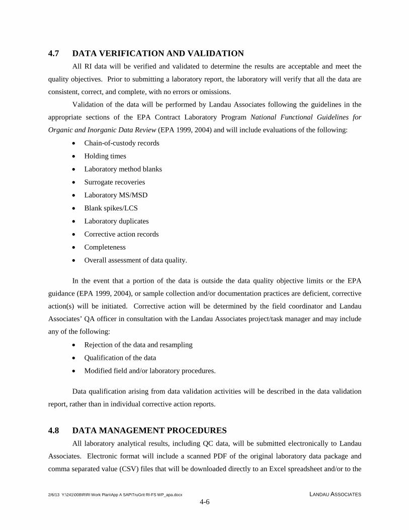
2/6/13 Y:\241\008\R\RI Work Plan\App A SAP\TruGrit RI-FS WP_apa.docx LANDAU ASSOCIATES 4-6
4.7 DATA VERIFICATION AND VALIDATION All RI data will be verified and validated to determine the results are acceptable and meet the
quality objectives. Prior to submitting a laboratory report, the laboratory will verify that all the data are
consistent, correct, and complete, with no errors or omissions.
Validation of the data will be performed by Landau Associates following the guidelines in the
appropriate sections of the EPA Contract Laboratory Program National Functional Guidelines for
Organic and Inorganic Data Review (EPA 1999, 2004) and will include evaluations of the following:
• Chain-of-custody records
• Holding times
• Laboratory method blanks
• Surrogate recoveries
• Laboratory MS/MSD
• Blank spikes/LCS
• Laboratory duplicates
• Corrective action records
• Completeness
• Overall assessment of data quality.
In the event that a portion of the data is outside the data quality objective limits or the EPA
guidance (EPA 1999, 2004), or sample collection and/or documentation practices are deficient, corrective
action(s) will be initiated. Corrective action will be determined by the field coordinator and Landau
Associates’ QA officer in consultation with the Landau Associates project/task manager and may include
any of the following:
• Rejection of the data and resampling
• Qualification of the data
• Modified field and/or laboratory procedures.
Data qualification arising from data validation activities will be described in the data validation
report, rather than in individual corrective action reports.
4.8 DATA MANAGEMENT PROCEDURES All laboratory analytical results, including QC data, will be submitted electronically to Landau
Associates. Electronic format will include a scanned PDF of the original laboratory data package and
comma separated value (CSV) files that will be downloaded directly to an Excel spreadsheet and/or to the

2/6/13 Y:\241\008\R\RI Work Plan\App A SAP\TruGrit RI-FS WP_apa.docx LANDAU ASSOCIATES 4-7
project database. The laboratory data package should include a case narrative along with analytical and
quality control results. Following validation of the data, any qualifiers will be added to the Excel
spreadsheets and project database. All survey data will be provided electronically in a format that can be
downloaded into an Excel spreadsheet. All field data will be entered into an Excel spreadsheet and
verified to determine all entered data is correct and without omissions and errors. Following receipt of all
RI data and all survey data, water level measurements, field parameters, and analytical results will be
formatted electronically and uploaded to Ecology’s Environmental Information Management (EIM)
system.

2/6/13 Y:\241\008\R\RI Work Plan\App A SAP\TruGrit RI-FS WP_apa.docx LANDAU ASSOCIATES 5-1
5.0 HEALTH AND SAFETY
A project health and safety plan for implementation of field activities described in the Work Plan
and this SAP is provided in Appendix C of the main document. All Landau Associates employees will
follow the procedures described in this plan. Landau Associates subcontractors will either adopt this plan
or prepare their own plan that is at least as protective as this plan.
2/6/13 Y:\241\008\R\RI Work Plan\App A SAP\TruGrit RI-FS WP_apa.docx LANDAU ASSOCIATES 6-1
6.0 REFERENCES
Ecology. 2008. Sediment Sampling and Analysis Plan Appendix. Publication No. 03-09-043. Washington State Department of Ecology. February. EPA. 2004. Contract Laboratory Program National Functional Guidelines for Inorganic Data Review. U.S. Environmental Protection Agency. October. EPA. 2000. Collecting Water Quality Samples for Dissolved Metals in Water. U.S. Environmental Protection Agency, Region 6. January 13. EPA. 1999. USEPA Contract Laboratory Program National Functional Guidelines for Organic Data Review. EPA-540/R-99-008. Office of Emergency and Remedial Response, U.S. Environmental Protection Agency. Washington, D.C. October. Landau Associates. 2009. Report: Tru-Grit Facility Sediment Sampling and Analysis Results Tacoma, Washington. Prepared for CanAm Minerals, Inc. July 22.

0 60 120
Scale in Feet
Source: Google Earth Pro 2010; Aerial dated 04-30-2009
Note
1. Black and white reproduction of this colororiginal may reduce its effectiveness andlead to incorrect interpretation.
Tru-Grit FacilityTacoma, Washington Sampling Locations
FigureLAN
DA
U A
SS
OC
IATE
S, I
NC
. | V
:\241
\008
\010
.013
\Sam
pLoc
s.dw
g (A
) "Fi
gure
A-1
" 2/6
/201
3Legend
Proposed Upland Surface Soil Sample Location
Proposed Beach Area Sediment Sample Location
Proposed Subtidal Area Sediment Sample Location
2008 Sediment Sample Location
Proposed Surface Grab Sample for SMS Suiteand Core SampleParcel Boundary

Blair Waterway
TRU-GRIT
GRAYMONT WESTERN
ORION MARINE
TOTE
Alexander Avenue
East 1
1th Stre
et
BSG-1
BSG-2
0 300 600
Scale in Feet
Source: Google Earth Pro 2010
Tru-Grit FacilityTacoma, Washington Background Sample Locations
Figure
LANDAU ASSOCIATES, INC. | V:\241\008\010.013\BkgrndSampLocs.dwg (A) "Figure A-2" 2/5/2013
LegendParcel Boundary Line
Note
1. Black and white reproduction of this colororiginal may reduce its effectiveness andlead to incorrect interpretation.
Background Grab Sample Location

TABLE A-1SEDIMENT SAMPLE LOCATIONS AND ELEVATIONS
TRU-GRIT FACILITYTACOMA, WASHINGTON
Page 1 of 1
2/6/2013Y:\241\008\R\RI Work Plan\App A SAP\Appendix A Tables\Copy of TruGrit EDR RI-FS WP_tbA-1_rev LANDAU ASSOCIATES
Sample Location Northing (a) Easting (a) Elevation (b)SG-1 712778.7 1168493.7 BeachSG-2 712732.1 1168591.5 BeachSG-3 712670.1 1168660.7 BeachSG-4 712614.1 1168657.1 BeachSG-5 712724.9 1168542.8 at or above MLLWSG-6 712675.3 1168594.0 at or above MLLWSG-7 712629.7 1168641.0 at or above MLLWSG-8 712691.6 1168510.6 at or above MLLWSG-9 712642.0 1168561.7 -11.1
SG-10 712599.1 1168611.2 -8.6SG-11 712655.4 1168475.5 -27.0SG-12 712605.8 1168526.6 -27.4SG-13 712554.5 1168581.3 -26.5SG-14 712479.0 1168643.7 -23.1SG-15 712384.8 1168735.3 -25.7SG-16 712620.1 1168441.3 -30.2SG-17 712565.1 1168496.7 -31.6SG-18 712505.8 1168556.2 -34.2SG-19 712402.6 1168651.2 -40.2SG-20 712528.6 1168461.2 -49.6SG-21 712425.6 1168560.7 -51.0SG-22 712315.8 1168668.3 -50.4SG-23 712590.7 1168692.1 BeachSG-24 712702.7 1168627.1 BeachBSG-1 712242.7 1168110.6 -45.1BSG-2 713348.9 1167715.4 -47.8
G-5 712555.6 1168615.7 -18.3U-1 712747.2 1168605.3 aprox. 14U-2 712682.4 1168672.5 aprox. 14U-3 712664.9 1168697.6 aprox. 14U-4 712646.4 1168780.0 aprox. 16U-5 712662.1 1168795.9 aprox. 16U-6 712720.4 1168788.0 aprox. 16
(a) Washington State Plane North Zone coordinate system [North America Datum (NAD) 83] (b) Feet Mean Lower Low Water

TABLE A-2SAMPLE SIZE, CONTAINERS, AND ANALYTICAL METHODS
TRU-GRIT FACILITYTACOMA, WASHINGTON
Page 1 of 1
2/6/2013Y:\241\008\R\RI Work Plan\App A SAP\Appendix A Tables\TruGrit EDR RI-FS WP_tbA-2 LANDAU ASSOCIATES
Metals 8 oz - WMG with teflon-lined lid Cool, 4o C 6 months, 28 days for mercuryVolatiles 2 oz - WMG with teflon-lined lid Cool, 4o C 14 days, 6 months (b)Semivolatiles 8 oz - WMG with teflon-lined lid Cool, 4o C 14 days (a), 1 year (b) PCBs 8 oz - WMG with teflon-lined lid Cool, 4o C 14 days (a), 1 year (b) Pesticides 8 oz - WMG with teflon-lined lid Cool, 4o C 14 days (a), 1 year (b) TOC 4 oz - WMG with teflon-lined lid Cool, 4o C 28 days, 6 months (b)Total Solids 4 oz - WMG with septa lid Cool, 4o C 14 days, 6 months (b)
PCBs = Polychlorinated BiphenylsTOC= Total Organic CarbonWMG = Wide Mouth Glass oz = ounceso C = degrees CelsiusEPA = U.S. Environmental Protection Agency
(a) Holding time shown is from sample collection to extraction; holding time from extraction to analysis is 40 days.(b) Holding time shown is from sample collection to extraction if sample is frozen.
PreservationSample Type Maximum Holding TimeContainer

TABLE A-3RECOMMENDED SAMPLE PREPARATION METHODS, CLEANUP METHODS,
ANALYTICAL METHODS, AND PRACTICAL QUANTITATION LIMITS FOR SEDIMENTSTRU-GRIT FACILITY
TACOMA, WASHINGTON
Page 1 of 2
2/6/2013Y:\241\008\R\RI Work Plan\App A SAP\Appendix A Tables\TruGrit EDR RI-FS WP_tbA-3 LANDAU ASSOCIATES
Chemical
RecommendedSample Preparation
Methods (a)
Recommended Sample Cleanup
Methods (b)Recommended
Analytical Methods (c) Recommended PQLs (d,e)
Metals (mg/kg dry weight) Arsenic PSEP/3050B -- 6010B/6020/7061A 19Cadmium PSEP/3050B -- 6010B/6020/7131A 1.7Chromium PSEP/3050B -- 6010B/6020/7191 87Copper PSEP/3050B -- 6010B/6020 130Lead PSEP/3050B -- 6010B/6020 150Mercury -- (f) -- 7471A/245.5 0.14Nickel PSEP/3050B 6010B/6020 47Silver PSEP/3050B -- 6010B/6020 2Zinc PSEP/3050B -- 6010B/6020 137
Nonionizable Organic Compounds (µg/kg dry weight
or as listed)
LPAH Compounds Naphthalene 3540C/3550B/3545 3640A/3660B 8270C/1625C 700Acenaphthylene 3540C/3550B/3545 3640A/3660B 8270C/1625C 433Acenaphthene 3540C/3550B/3545 3640A/3660B 8270C/1625C 167Fluorene 3540C/3550B/3545 3640A/3660B 8270C/1625C 180Phenanthrene 3540C/3550B/3545 3640A/3660B 8270/1625C 500Anthracene 3540C/3550B/3545 3640A/3660B 8270C/1625C 3202-Methylnaphthalene 3540C/3550B/3545 3640A/3660B 8270C/1625C 223
HPAH Compounds Fluoranthene 3540C/3550B/3545 3640A/3660B 8270C/1625C 567Pyrene 3540C/3550B/3545 3640A/3660B 8270C/1625C 867Benz[a]anthracene 3540C/3550B/3545 3640A/3660B 8270C (h) / 1625C 433Chrysene 3540C/3550B/3545 3640A/3660B 8270C (h) / 1625C 467Total benzofluoranthenes (g) 3540C/3550B/3545 3640A/3660B 8270C (h) / 1625C 1067Benzo[a]pyrene 3540C/3550B/3545 3640A/3660B 8270C (h) / 1625C 533Indeno[1,2,3-cd]pyrene 3540C/3550B/3545 3640A/3660B 8270C (h) / 1625C 200Dibenz[a,h]anthracene 3540C/3550B/3545 3640A/3660B 8270C (h) / 1625C 77Benzo[ghi]perylene 3540C/3550B/3545 3640A/3660B 8270C/1625C 223
Chlorinated Benzenes 1,2-Dichlorobenzene 3540C/3550B/3545 3640A/3660B 8270C (h) / 1625C 351,4-Dichlorobenzene 3540C/3550B/3545 3640A/3660B 8270C (h) / 1625C 371,2,4-Trichlorobenzene 3540C/3550B/3545 3640A/3660B 8270C (h) / 1625C 31Hexachlorobenzene 3540C/3550B/3545 3640A/3660B 8270C (h) / 1625C 22
Phthalate Esters Dimethyl phthalate 3540C/3550B/3545 3640A/3660B 8270C/1625C 24Diethyl phthalate 3540C/3550B/3545 3640/A3660B 8270C/1625C 67Di-n-butyl phthalate 3540C/3550B/3545 3640A/3660B 8270C/1625C 467Butyl benzyl phthalate 3540C/3550B/3545 3640A/3660B 8270C/1625C 21Bis[2-ethylhexyl]phthalate 3540C/3550B/3545 3640A/3660B 8270C/1625C 433Di-n-octyl phthalate 3540C/3550B/3545 3640A/3660B 8270C/1625C 2067
Miscellaneous Extractable Compounds (µg/kg dry weight
or as listed) Dibenzofuran 3540C/3550B/3545 3640A/3660B 8270C/1625C 180Hexachlorobutadiene 3540C/3550B/3545 3640A/3660B 8270C/1625C 11N-nitrosodiphenylamine 3540C/3550B/3545 3640A/3660B 8270C/1625C 28PCBs PCB Aroclors® 3540/3550 3620B/3640A/3660B 8082 6

TABLE A-3RECOMMENDED SAMPLE PREPARATION METHODS, CLEANUP METHODS,
ANALYTICAL METHODS, AND PRACTICAL QUANTITATION LIMITS FOR SEDIMENTSTRU-GRIT FACILITY
TACOMA, WASHINGTON
Page 2 of 2
2/6/2013Y:\241\008\R\RI Work Plan\App A SAP\Appendix A Tables\TruGrit EDR RI-FS WP_tbA-3 LANDAU ASSOCIATES
Chemical
RecommendedSample Preparation
Methods (a)
Recommended Sample Cleanup
Methods (b)Recommended
Analytical Methods (c) Recommended PQLs (d,e)
Volatile Organic Compounds Ionizable Organic Compounds Phenol 3540C/3550B/3545 3640A/3660B 8270C/1625C 1402-Methylphenol 3540C/3550B/3545 3640A/3660B 8270C/1625C 634-Methylphenol 3540C/3550B/3545 3640A/3660B 8270C/1625C 2232,4-Dimethylphenol 3540C/3550B/3545 3640A/3660B 8270C/1625C 29Pentachlorophenol 3540C/3550B/3545 3640A/3660B 8270C/1625C 120Benzyl alcohol 3540C/3550B/3545 3640A/3660B 8270C/1625C 57Benzoic acid 3540C/3550B/3545 3640A/3660B 8270C/1625C 217
Conventional Sediment Variables Grain size -- (j) -- Plumb (1981) 1%TOC -- (j) -- 9060 0.10%
Protocol, Appendix A (PSWQA, 1996) Krone 1998 PCB - polychlorinated biphenyl mg/L = milligrams per liter
73 ug TBT/Kg Bulk PCDD = polychlorinated dibenzo-p-dioxins mL = milliliter.05 ug TBT/L pour water PCDF = polychlorinated dibenzofurans ng/kg = nanograms per kilogramEPA - U.S. Environmental Protection Agency PQL = Practical Quantitation Limits µg/kg - micrograms per kilogramGPC - gel permeation chromatography PSEP - Puget Sound Estuary ProgramHPAH - high molecular weight polycyclic aromatic hydrocarbon RA/FA = LAET = Lowest Apparent Effects Threshold Sb = AntimonyLPAH - low molecular weight polycyclic aromatic hydrocarbon TOC - total organic carbonNCASI = National Council for Air and Stream Improvement, Inc. VOC = Volatile Organic CompoundsNi = Nickel
(a) Recommended sample preparation methods are: - PSEP (1997a)
(b) Recommended sample cleanup methods are:
should be used.
and EPA (1986).(c) Recommended analytical methods are:
- Method 1613 - analytical method from EPA-821/B-94-005 (EPA 1994c). - Method 1624C/1625C - isotope dilution method. - NCASI analytical methods. - Plumb (1981) - EPA/U.S. Army Corps of Engineers Technical Report EPA/CE-81-1 - PSEP (1986). - Acid volatile sulfide method for sediment (EPA 1991).(d) To achieve the recommended PQLs for organic compounds, it may be necessary to use a larger sample size (approximately 100 g), a smaller final
(f) The sample digestion method for mercury is described in the analytical method (Method 7471A, September 1994).(g) Total benzofluoranthenes represent the sum of the b, j, and k isomers.
(i) Sample preparation methods for VOCs analyses are described in the analytical methods.(j) Sample preparation methods for sediment conventional analyses are described in the analytical methods.
- Method 3050B and 3500 series - sample preparation methods from SW-846 (EPA 1996) and subjected to changes by EPA updates.
- Sample extracts subjected to GPC cleanup follow the procedures specified by EPA SW-846 Method 3640A. Special care should be used during GPC to minimize loss of analytes. - If sulfur is present in the samples (as is common in most marine sediments), cleanup procedures specified by EPA SW-846 Method 3660B
- All PCB extracts should be subjected to sulfuric acid/permanganate cleanup as specified by EPA SW-846 Method 3665A. - Additional cleanup procedures may be necessary on a sample-by-sample basis. Alternative cleanup procedures are described in PSEP (1997b)
appendix B–Guidance for Selected Ion Monitoring (PSEP 1997b).
1,2-dichlorobenzene, 1,2,4-trichlorobenzene, hexachlorobenzene, hexachlorobutadiene, n-nitrosodiphenylamine, 2-methylphenol, 2,4-dimethylphenol, and benzyl alcohol, for which the recommended maximum detection limit is equal to the full value of the 1988 dry weight LAET.
human health criteria levels or when TOC levels elevate detection limits above ecological criteria levels. See PSEP organics chapter,
- The SW-846 and updates are available from the web site at: http://www.epa.gov/epaoswer/hazwaste/test/sw846.htm.
otherwise indicated. For sediment samples with low TOC, it may be necessary to achieve even lower detection limits for certain analytes in order to compare the TOC-normalized concentrations with applicable numerical criteria.(e) The recommended PQLs are based on a value equal to one third of the 1988 dry weight LAET value (Barrick et al 1988) except for the following chemicals:
(h) Selected ion monitoring may improve the sensitivity of method 8270C and is recommended in cases when detection limits must be lowered to
extract volume for gas chromatography/mass spectrometry analyses (0.5 mL), and one of the recommended sample cleanup methods, as necessary, to reduce interference, using different analytical methods with better sensitivity. Detection limits are on a dry-weight basis unless
- Method 6000, 7000, 8000, and 9000 series - analytical methods from SW-846 (EPA 1986) and updates.
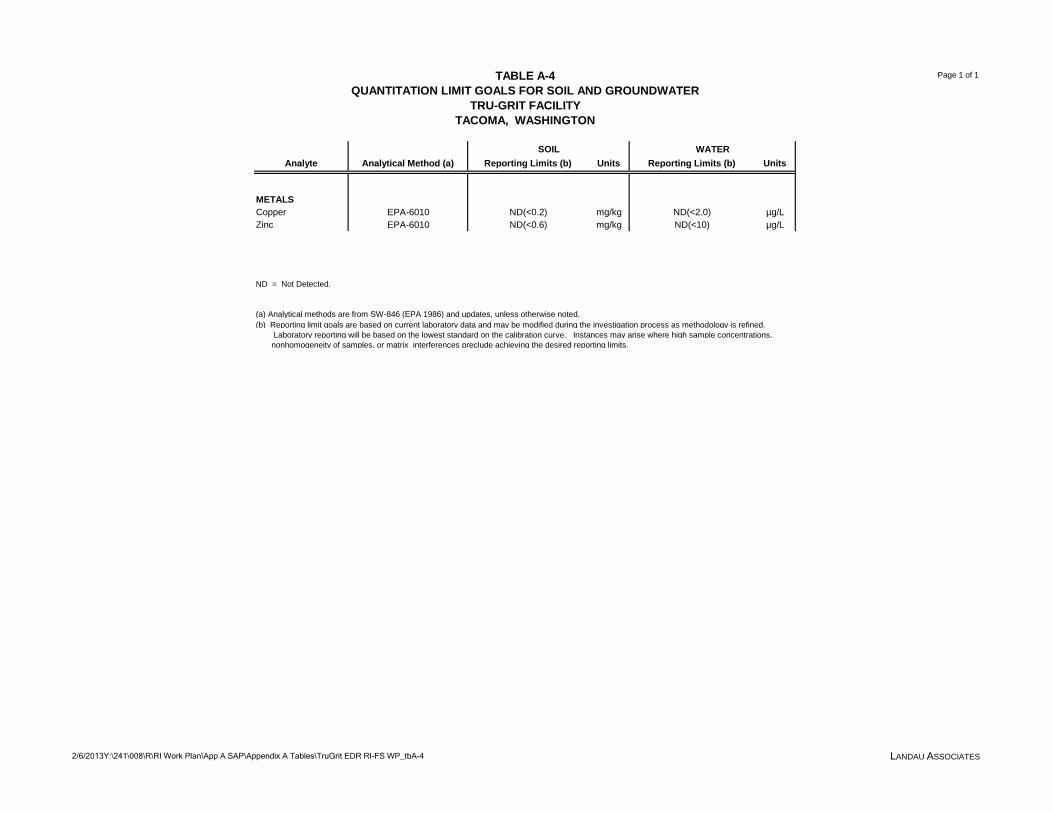
TABLE A-4QUANTITATION LIMIT GOALS FOR SOIL AND GROUNDWATER
TRU-GRIT FACILITYTACOMA, WASHINGTON
Page 1 of 1
2/6/2013Y:\241\008\R\RI Work Plan\App A SAP\Appendix A Tables\TruGrit EDR RI-FS WP_tbA-4 LANDAU ASSOCIATES
Analyte Analytical Method (a) Reporting Limits (b) Units Reporting Limits (b) Units
METALSCopper EPA-6010 ND(<0.2) mg/kg ND(<2.0) µg/LZinc EPA-6010 ND(<0.6) mg/kg ND(<10) µg/L
ND = Not Detected.
(a) Analytical methods are from SW-846 (EPA 1986) and updates, unless otherwise noted.(b) Reporting limit goals are based on current laboratory data and may be modified during the investigation process as methodology is refined. Laboratory reporting will be based on the lowest standard on the calibration curve. Instances may arise where high sample concentrations, nonhomogeneity of samples, or matrix interferences preclude achieving the desired reporting limits.
SOIL WATER

TABLE A-5LABORATORY QC SAMPLE ACCEPTANCE CRITERIA
SEDIMENT
Page 1 of 4
2/6/2013Y:\241\008\R\RI Work Plan\App A SAP\Appendix A Tables\TruGrit EDR RI-FS WP_tbA-5 LANDAU ASSOCIATES
Analyte Description CAS Number/ Method
LCSREC - Recovery
Low
LCSREC - Recovery
High
LCSREC - Units
LCSRPD - Precision
LCSRPD - Units
MSREC - Recovery
Low
MSREC - Recovery
High
MSREC - Units
MSRPD - Precision
MSRPD - Units
SUREC - Recovery
Low
SUREC - Recovery
High
SUREC - Units
Metals (ICP) 6010BArsenic 7440-38-2 80 120 % 20 % 80 120 % 20 % -- -- --
Cadmium 7440-43-9 80 120 % 20 % 80 120 % 20 % -- -- --
Chromium 7440-47-3 80 120 % 20 % 80 120 % 20 % -- -- --
Copper 7440-50-8 80 120 % 20 % 80 120 % 20 % -- -- --
Lead 7439-92-1 80 120 % 20 % 80 120 % 20 % -- -- --
Silver 7440-22-4 75 120 % 20 % 75 120 % 20 % -- -- --
Zinc 7440-66-6 80 120 % 20 % 80 120 % 20 % -- -- --
Organochlorine Pesticides (GC)
8081A
DCB Decachlorobiphenyl
2051-24-3 -- -- -- -- -- -- -- -- -- -- 40 158 %
Tetrachloro-m-xylene 877-09-8 -- -- -- -- -- -- -- -- -- -- 49 123 %
Hexachlorobenzene 118-74-1 10 188 % 37 % 10 188 % 30 % -- -- --Hexachlorobutadiene 87-68-3 37 119 % 39 % 37 119 % 30 % -- -- --
TOC (Puget Sound) 9060_PSEP
Total Organic Carbon 7440-44-0 27.8 170 % 35 % 50 140 % 35 % -- -- --
Percent Moisture Moisture
Percent Solids STL00234 80 120 % -- -- -- -- -- -- -- -- -- --
Percent Moisture STL00177 80 120 % -- -- -- -- -- -- -- -- -- --
Total Solids STL00291 80 120 % -- -- -- -- -- -- -- -- -- --
Semivolatile Organic Compounds (GC/MS)
8270C
2-Fluorophenol 367-12-4 -- -- -- -- -- -- -- -- -- -- 36 145 %

TABLE A-5LABORATORY QC SAMPLE ACCEPTANCE CRITERIA
SEDIMENT
Page 2 of 4
2/6/2013Y:\241\008\R\RI Work Plan\App A SAP\Appendix A Tables\TruGrit EDR RI-FS WP_tbA-5 LANDAU ASSOCIATES
Phenol-d5 4165-62-2 -- -- -- -- -- -- -- -- -- -- 38 149 %
2,4,6-Tribromophenol 118-79-6 -- -- -- -- -- -- -- -- -- -- 28 143 %
Nitrobenzene-d5 4165-60-0 -- -- -- -- -- -- -- -- -- -- 38 141 %
2-Fluorobiphenyl 321-60-8 -- -- -- -- -- -- -- -- -- -- 42 140 %
Terphenyl-d14 1718-51-0 -- -- -- -- -- -- -- -- -- -- 42 151 %
Phenol 108-95-2 66 126 % 26 % 70 140 % 26 % -- -- --
1,4-Dichlorobenzene 106-46-7 62 132 % 32 % 75 125 % 32 % -- -- --
Benzyl alcohol 100-51-6 42 147 % 60 % 55 125 % 60 % -- -- --
1,2-Dichlorobenzene 95-50-1 68 118 % 60 % 75 125 % 60 % -- -- --
2-Methylphenol 95-48-7 56 121 % 25 % 75 130 % 25 % -- -- --
3 & 4 Methylphenol 15831-10-4 61 126 % 27 % 75 130 % 27 % -- -- --
2,4-Dimethylphenol 105-67-9 58 133 % 60 % 65 140 % 60 % -- -- --
Benzoic acid 65-85-0 10 130 % 60 % 20 175 % 60 % -- -- --
1,2,4-Trichlorobenzene
120-82-1 63 128 % 28 % 70 125 % 28 % -- -- --
Naphthalene 91-20-3 64 129 % 26 % 75 125 % 26 % -- -- --
Hexachlorobutadiene 87-68-3 59 134 % 60 % 75 125 % 60 % -- -- --
2-Methylnaphthalene 91-57-6 65 125 % 27 % 75 125 % 27 % -- -- --
Dimethyl phthalate 131-11-3 65 125 % 60 % 60 160 % 60 % -- -- --
Acenaphthylene 208-96-8 69 129 % 28 % 75 125 % 28 % -- -- --
Acenaphthene 83-32-9 65 130 % 27 % 75 125 % 27 % -- -- --
Dibenzofuran 132-64-9 70 125 % 60 % 75 125 % 60 % -- -- --
Diethyl phthalate 84-66-2 64 129 % 26 % 60 155 % 26 % -- -- --
Fluorene 86-73-7 68 128 % 31 % 75 125 % 31 % -- -- --
N-Nitrosodiphenylamine
86-30-6 88 153 % 60 % 75 125 % 60 % -- -- --
Hexachlorobenzene 118-74-1 61 136 % 60 % 75 125 % 60 % -- -- --
Pentachlorophenol 87-86-5 29 124 % 68 % 55 125 % 68 % -- -- --

TABLE A-5LABORATORY QC SAMPLE ACCEPTANCE CRITERIA
SEDIMENT
Page 3 of 4
2/6/2013Y:\241\008\R\RI Work Plan\App A SAP\Appendix A Tables\TruGrit EDR RI-FS WP_tbA-5 LANDAU ASSOCIATES
Phenanthrene 85-01-8 65 125 % 28 % 75 125 % 28 % -- -- --
Anthracene 120-12-7 73 123 % 27 % 75 125 % 27 % -- -- --
Di-n-butyl phthalate 84-74-2 69 124 % 60 % 55 145 % 60 % -- -- --
Fluoranthene 206-44-0 61 121 % 36 % 70 125 % 36 % -- -- --
Pyrene 129-00-0 54 134 % 31 % 75 125 % 31 % -- -- --
Butyl benzyl phthalate 85-68-7 65 140 % 60 % 55 145 % 60 % -- -- --
Benzo[a]anthracene 56-55-3 64 124 % 27 % 75 125 % 27 % -- -- --
Chrysene 218-01-9 71 126 % 26 % 75 125 % 26 % -- -- --
Bis(2-ethylhexyl) phthalate
117-81-7 64 144 % 60 % 55 145 % 60 % -- -- --
Di-n-octyl phthalate 117-84-0 58 148 % 31 % 55 145 % 31 % -- -- --
Benzofluoranthene 56832-73-6 57 137 % 31 % 75 125 % 31 % -- -- --
Benzo[a]pyrene 50-32-8 68 128 % 30 % 75 125 % 30 % -- -- --
Indeno[1,2,3-cd]pyrene
193-39-5 59 139 % 29 % 75 125 % 29 % -- -- --
Dibenz(a,h)anthracene
53-70-3 57 142 % 30 % 75 125 % 30 % -- -- --
Benzo[g,h,i]perylene 191-24-2 57 142 % 28 % 75 125 % 28 % -- -- --
Polychlorinated Biphenyls (PCBs) by Gas Chromatography
8082
Tetrachloro-m-xylene 877-09-8 -- -- -- -- -- -- -- -- -- -- 45 135 %
DCB Decachlorobiphenyl
2051-24-3 -- -- -- -- -- -- -- -- -- -- 50 140 %
PCB-1016 12674-11-2 40 140 % 20 % 40 140 % 20 % -- -- --
PCB-1232 11141-16-5 50 150 % 30 % 50 150 % 30 % -- -- --
PCB-1242 53469-21-9 57 128 % 20 % 57 128 % 20 % -- -- --
PCB-1254 11097-69-1 65 132 % 20 % 65 132 % 20 % -- -- --
PCB-1260 11096-82-5 60 130 % 20 % 60 130 % 20 % -- -- --
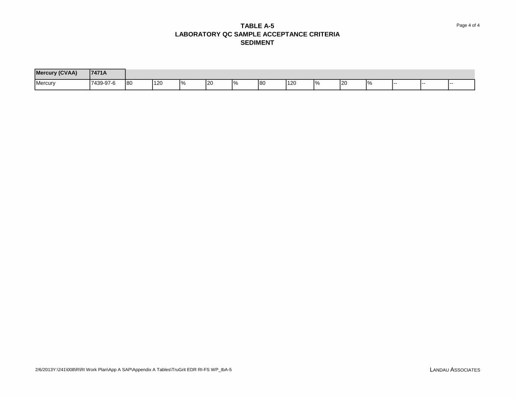
TABLE A-5LABORATORY QC SAMPLE ACCEPTANCE CRITERIA
SEDIMENT
Page 4 of 4
2/6/2013Y:\241\008\R\RI Work Plan\App A SAP\Appendix A Tables\TruGrit EDR RI-FS WP_tbA-5 LANDAU ASSOCIATES
Mercury (CVAA) 7471A
Mercury 7439-97-6 80 120 % 20 % 80 120 % 20 % -- -- --
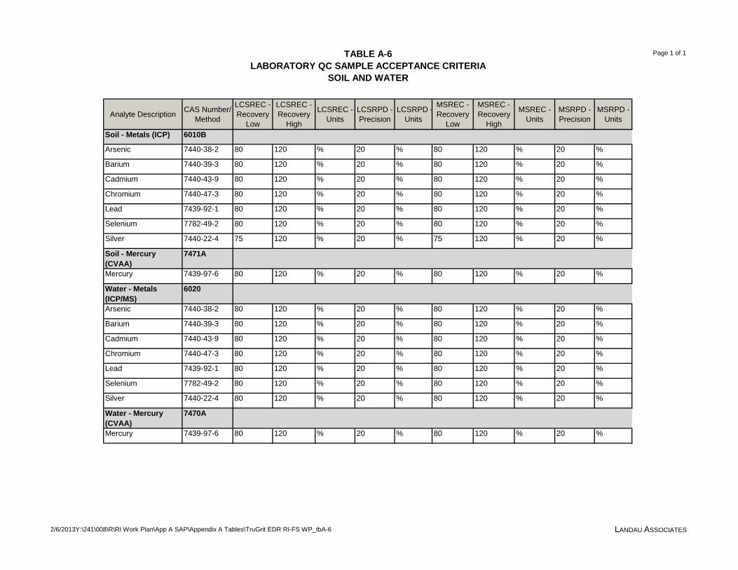
TABLE A-6LABORATORY QC SAMPLE ACCEPTANCE CRITERIA
SOIL AND WATER
Page 1 of 1
2/6/2013Y:\241\008\R\RI Work Plan\App A SAP\Appendix A Tables\TruGrit EDR RI-FS WP_tbA-6 LANDAU ASSOCIATES
Analyte Description CAS Number/ Method
LCSREC - Recovery
Low
LCSREC - Recovery
High
LCSREC - Units
LCSRPD - Precision
LCSRPD - Units
MSREC - Recovery
Low
MSREC - Recovery
High
MSREC - Units
MSRPD - Precision
MSRPD - Units
Soil - Metals (ICP) 6010B
Arsenic 7440-38-2 80 120 % 20 % 80 120 % 20 %
Barium 7440-39-3 80 120 % 20 % 80 120 % 20 %
Cadmium 7440-43-9 80 120 % 20 % 80 120 % 20 %
Chromium 7440-47-3 80 120 % 20 % 80 120 % 20 %
Lead 7439-92-1 80 120 % 20 % 80 120 % 20 %
Selenium 7782-49-2 80 120 % 20 % 80 120 % 20 %
Silver 7440-22-4 75 120 % 20 % 75 120 % 20 %
Soil - Mercury (CVAA)
7471A
Mercury 7439-97-6 80 120 % 20 % 80 120 % 20 %
Water - Metals (ICP/MS)
6020
Arsenic 7440-38-2 80 120 % 20 % 80 120 % 20 %
Barium 7440-39-3 80 120 % 20 % 80 120 % 20 %
Cadmium 7440-43-9 80 120 % 20 % 80 120 % 20 %
Chromium 7440-47-3 80 120 % 20 % 80 120 % 20 %
Lead 7439-92-1 80 120 % 20 % 80 120 % 20 %
Selenium 7782-49-2 80 120 % 20 % 80 120 % 20 %
Silver 7440-22-4 80 120 % 20 % 80 120 % 20 %
Water - Mercury (CVAA)
7470A
Mercury 7439-97-6 80 120 % 20 % 80 120 % 20 %
APPENDIX B
Health and Safety Plan

Page 1 of 14
2/6/13 Y:\241\008\R\RI Work Plan\App B HASP\TruGrit EDR RI-FS WP_apb.docx LANDAU ASSOCIATES
WORK LOCATION PERSONNEL PROTECTION AND SAFETY EVALUATION FORM
Attach Pertinent Documents/Data
Fill in Blanks As Appropriate Job No.: 241008
Prepared by: Kristin Hooper Reviewed by: Christine Kimmel Date: September 12, 2012 Date: October 5, 2012 1. Project Name: Tru Grit Facility
2. Location: 1110 Alexander Avenue, Tacoma, Washington
3. Anticipated Activities: Collection of soil and sediment samples. Sediment sampling in subtidal areas will be conducted by boat using a power-grab sampler and vibrocore. Sediment sampling in shoreline areas will be conducted with hand implements at low tide. Upland soil samples will be collected using hand implements. Groundwater sampling.
4. Size: Approximately 5 acres
5. Surrounding Population: Industrial
6. Buildings/Homes/Industry: Industrial properties and shipping
7. Topography: Level
8. Anticipated Weather: Variable weather, wind, rain, sun; Temperature, 30-70 °F
9. Unusual Features: Portion of property is upland and a portion is over water.
10. Site History: The facility stores and distributes a granular slag grit material, which is sold to roofing manufacturers and sandblasters under the name Tru-Grit Roofing Granules. Slag material is brought to the facility by barge from Canada. Once the barged material reaches the Tacoma site, a front-end loader and a ship-to-shore conveyance system are used to unload the barges when they arrive at the Tru-grit facility. The granular slag is transported by the conveyor system to a stacking conveyor, which places the slag onto an outdoor storage pile.
1. Background Review: Complete Partial
If partial, why?
2. Hazardous Level: B C D Unknown
A. WORK LOCATION DESCRIPTION
B. HAZARD DESCRIPTION

Page 2 of 14
2/6/13 Y:\241\008\R\RI Work Plan\App B HASP\TruGrit EDR RI-FS WP_apb.docx LANDAU ASSOCIATES
Justification: Existing data regarding site conditions and media handling procedures to minimize contact.
3. Types of Hazards: (Attach additional sheets as necessary)
A. Chemical Inhalation Explosive
Biological Ingestion O2 Def. Skin Contact
Describe: Accidental inhalation, ingestion or absorption of chemicals of potential concern during exploratory and sampling activities. Soil, groundwater and/or sediment potentially contaminated with metals (copper and zinc).
B. Physical Cold Stress Noise Heat Stress Other
Describe: Exposure to weather extremes. Potential drowning during over water activities.
C. Radiation
Describe:
4. Nature of Hazards:
Air Describe: Potential for airborn dust to be generated during sampling.
Soil Describe: Potential for contact with or ingestion of contaminated soil and sediment.
Surface Water Describe: Drowning exposure during over water activities.
Groundwater Describe: Potential for contact with or ingestion of contaminated
groundwater. .
Other Describe:

Page 3 of 14
2/6/13 Y:\241\008\R\RI Work Plan\App B HASP\TruGrit EDR RI-FS WP_apb.docx LANDAU ASSOCIATES
5. Chemical Contaminants of Concern N/A
Contaminant PEL
(ppm) I.D.L.H. (ppm)
Source/Quantity Characteristics Route of Exposure
Symptoms of Acute Exposure
Instruments Used to Monitor
Contaminant Copper 1 mg/m3 100 mg/m3 Present in soil, surface
water and sediment
Inhalation, ingestion, skin and eye contact
Irritation of eyes, nose, pharynx; nasal septum perforation; metallic taste; dermatitis
Dust control
Zinc 15 mg/m3 500 mg/m3 Present in soil, surface water and sediment
Inhalation Metal fume fever; chills, muscle ache, nausea, fever, dry throat, cough; lassitude; metallic taste; headache; blurred vision; low back pain; vomit; malaise; chest tight; difficulty breathing; rales; decreased pulmonary function
Dust control
Notes:

Page 4 of 14
2/6/13 Y:\241\008\R\RI Work Plan\App B HASP\TruGrit EDR RI-FS WP_apb.docx LANDAU ASSOCIATES
6. Physical Hazards of Concern N/A
Hazard Description Location Procedures Used to Monitor Hazard
Drowning Potential for drowning while sampling via boat.
On the water Coast Guard approved and non-altered personal floatation devices will be worn at all times while on the water. The buddy system (field team working in pairs) will be observed.
Slips, trips, and falls Pinch points
Working around sampling equipment.
Any area On sampling vessel
Alert observation of surroundings. Keep work area organized and free of debris. Be aware of potential pinch points, make eye contact with operator, and don’t wear loose clothing.
Page 5 of 14
2/6/13 Y:\241\008\R\RI Work Plan\App B HASP\TruGrit EDR RI-FS WP_apb.docx LANDAU ASSOCIATES
7. Work Location Instrument Readings N/A
Location:
Percent O2: Percent LEL:
Radioactivity: PID:
FID: Other:
Other: Other:
Other: Other:
Location:
Percent O2: Percent LEL:
Radioactivity: PID:
FID: Other:
Other: Other:
Other: Other:
Location:
Percent O2: Percent LEL:
Radioactivity: PID:
FID: Other:
Other: Other:
Other: Other:
Location:
Percent O2: Percent LEL:
Radioactivity: PID:
FID: Other:
Other: Other:
Other: Other: 8. Hazards Expected In Preparation For Work Assignment N/A
Describe:
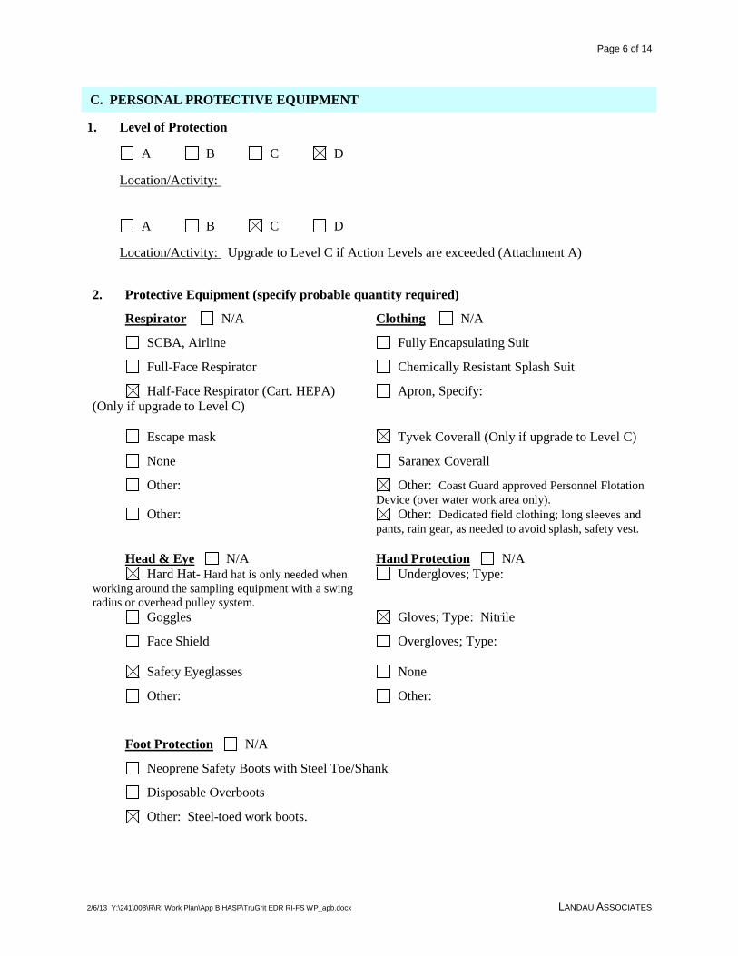
Page 6 of 14
2/6/13 Y:\241\008\R\RI Work Plan\App B HASP\TruGrit EDR RI-FS WP_apb.docx LANDAU ASSOCIATES
1. Level of Protection
A B C D
Location/Activity:
A B C D
Location/Activity: Upgrade to Level C if Action Levels are exceeded (Attachment A)
2. Protective Equipment (specify probable quantity required)
Respirator N/A Clothing N/A
SCBA, Airline Fully Encapsulating Suit
Full-Face Respirator Chemically Resistant Splash Suit
Half-Face Respirator (Cart. HEPA) (Only if upgrade to Level C)
Apron, Specify:
Escape mask Tyvek Coverall (Only if upgrade to Level C)
None Saranex Coverall
Other: Other: Coast Guard approved Personnel Flotation Device (over water work area only).
Other: Other: Dedicated field clothing; long sleeves and pants, rain gear, as needed to avoid splash, safety vest.
Head & Eye N/A
Hand Protection N/A
Hard Hat- Hard hat is only needed when working around the sampling equipment with a swing radius or overhead pulley system.
Undergloves; Type:
Goggles Gloves; Type: Nitrile
Face Shield Overgloves; Type:
Safety Eyeglasses None
Other: Other:
Foot Protection N/A
Neoprene Safety Boots with Steel Toe/Shank
Disposable Overboots
Other: Steel-toed work boots.
C. PERSONAL PROTECTIVE EQUIPMENT

Page 7 of 14
2/6/13 Y:\241\008\R\RI Work Plan\App B HASP\TruGrit EDR RI-FS WP_apb.docx LANDAU ASSOCIATES
3. Monitoring Equipment N/A
CGI PID
O2 Meter FID
Rad Survey Other: HAM meter
Detector Tubes (optional)
Type:
PERSONAL DECONTAMINATION
Required Not Required
If required, describe: Wash hands and face with water and soap before each break. Minimize hand to mouth actions while on site. Use disposal nitrile gloves and change gloves frequently. EQUIPMENT DECONTAMINATION
Required Not Required
If required, describe and list equipment: Sediment sampling device(s) will be decontaminated between exploration locations using an alconox wash. Non-dedicated sampling equipment will be decontaminated between sampling intervals using a three-step process:
• Remove visual contamination and wash with a mixture of Alconox soap and clean site or tap water
• Rinse with clean site or tap water • Rinse with deionized water (upland area only)
D. DECONTAMINATION

Page 8 of 14
2/6/13 Y:\241\008\R\RI Work Plan\App B HASP\TruGrit EDR RI-FS WP_apb.docx LANDAU ASSOCIATES
Name Work Location Title/Task Medical Current
Fit Test Current
1. Jennifer Wynkoop Project Manager
2. Lauren Knickrehm Project Engineer/Task Manager
3. Steven Shaw Staff
4.
5.
6.
7.
8.
9.
10.
Site Safety Coordinator: Steven Shaw
E. PERSONNEL

Page 9 of 14
2/6/13 Y:\241\008\R\RI Work Plan\App B HASP\TruGrit EDR RI-FS WP_apb.docx LANDAU ASSOCIATES
Task No. Description Preliminary Schedule 1 Soil sampling, sediment sampling via boat. Fall 2012
F. ACTIVITIES COVERED UNDER THIS PLAN

Page 10 of 14
2/6/13 Y:\241\008\R\RI Work Plan\App B HASP\TruGrit EDR RI-FS WP_apb.docx LANDAU ASSOCIATES
N/A Name and Address of Subcontractor:: Unknown
EVALUATION CRITERIA
Item Adequate Inadequate Comments Medical Surveillance Program
Personal Protective Equipment Availability
Onsite Monitoring Equipment Availability
Safe Working Procedures Specification
Training Protocols
Ancillary Support Procedures (if any)
Emergency Procedures
Evacuation Procedures Contingency Plan
Decontamination Procedures Equipment
Decontamination Procedures Personnel
GENERAL HEALTH AND SAFETY PROGRAM EVALUATION: Adequate Inadequate
Additional Comments:
Evaluation Conducted By: Date:
G. SUBCONTRACTOR’S HEALTH AND SAFETY PROGRAM EVALUATION
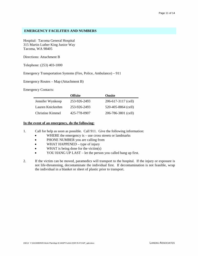
Page 11 of 14
2/6/13 Y:\241\008\R\RI Work Plan\App B HASP\TruGrit EDR RI-FS WP_apb.docx LANDAU ASSOCIATES
Hospital: Tacoma General Hospital 315 Martin Luther King Junior Way Tacoma, WA 98405 Directions: Attachment B Telephone: (253) 403-1000 Emergency Transportation Systems (Fire, Police, Ambulance) – 911 Emergency Routes – Map (Attachment B) Emergency Contacts:
Offsite Onsite Jennifer Wynkoop 253-926-2493 206-617-3117 (cell) Lauren Knickrehm 253-926-2493 520-405-8864 (cell)
Christine Kimmel 425-778-0907 206-786-3801 (cell) In the event of an emergency, do the following: 1. Call for help as soon as possible. Call 911. Give the following information:
• WHERE the emergency is – use cross streets or landmarks • PHONE NUMBER you are calling from • WHAT HAPPENED – type of injury • WHAT is being done for the victim(s) • YOU HANG UP LAST – let the person you called hang up first.
2. If the victim can be moved, paramedics will transport to the hospital. If the injury or exposure is
not life-threatening, decontaminate the individual first. If decontamination is not feasible, wrap the individual in a blanket or sheet of plastic prior to transport.
EMERGENCY FACILITIES AND NUMBERS
Page 12 of 14
2/6/13 Y:\241\008\R\RI Work Plan\App B HASP\TruGrit EDR RI-FS WP_apb.docx LANDAU ASSOCIATES
HEALTH AND SAFETY PLAN APPROVAL/SIGN OFF FORMAT
I have read, understood, and agreed with the information set forth in this Health and Safety Plan (and attachments) and discussed in the Personnel Health and Safety briefing.
Name
Signature Date
Name
Signature
Date
Name
Signature
Date
Name
Signature
Date
Name
Steven Shaw
Signature Date
Site Safety Coordinator
Christine Kimmel
Signature Date
Landau Health and Safety Manager
Jennifer Wynkoop
Signature Date
Project Manager Signature Date
Personnel Health and Safety Briefing Conducted By:
Name Signature Date

Page 13 of 14
2/6/13 Y:\241\008\R\RI Work Plan\App B HASP\TruGrit EDR RI-FS WP_apb.docx LANDAU ASSOCIATES
ATTACHMENT A
ACTION LEVELS FOR RESPIRATORY PROTECTION
Monitoring Parameter Reading Level of Protection

Page 14 of 14
2/6/13 Y:\241\008\R\RI Work Plan\App B HASP\TruGrit EDR RI-FS WP_apb.docx LANDAU ASSOCIATES
ATTACHMENT B
MAP AND DIRECTIONS TO HOSPITAL
Tacoma General Hospital 315 Martin Luther King Junior Way Tacoma, WA 98405 (253) 403-1000 Emergency: 911

APPENDIX C
Ship-To-Shore Conveyor System Diagram


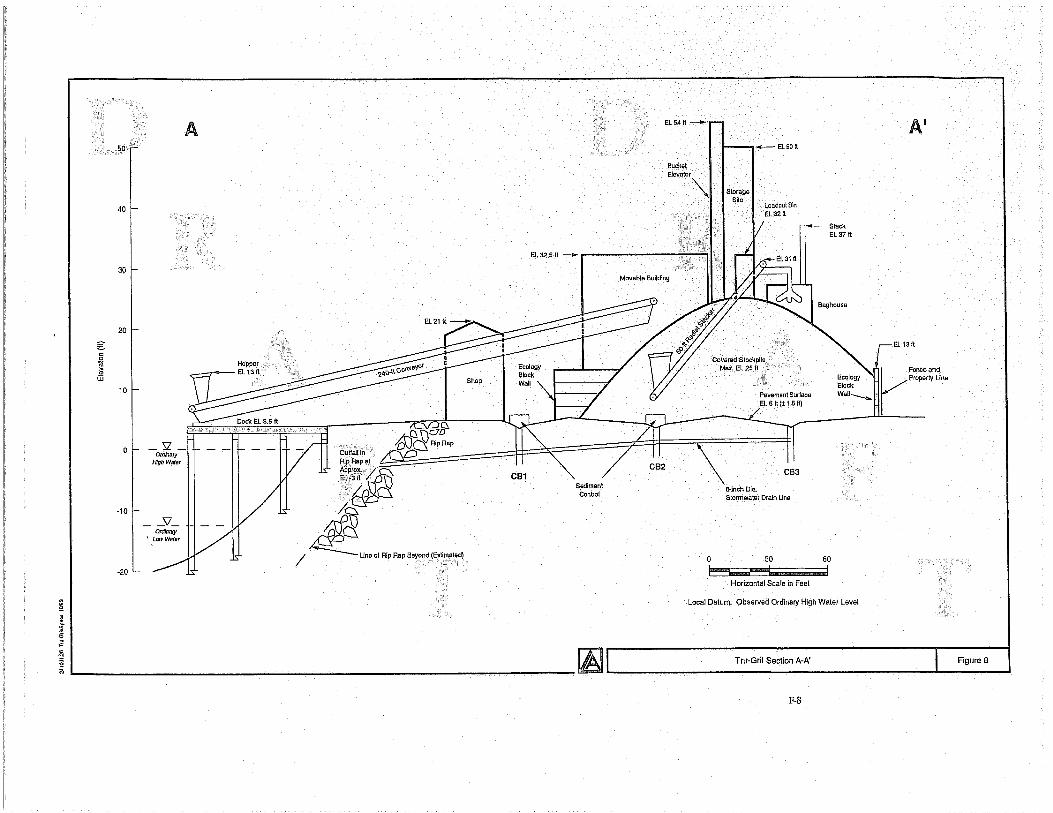

APPENDIX D
Terrestrial Ecological Exclusion Form

Recommended