PROPERTY MANAGEMENT SYSTEM
COMMUNICATION INTERFACE SPECIFICATION
NEC America, Inc.
NDA-30115-001Revision 1.0June, 1998
Stock # 241727

LIABILITY DISCLAIMER
NEC America reserves the right to change the specifications, functions, or features in this document at any time without notice. NEC America has prepared this document for use by its employees and customers. The information contained herein is the property of NEC America and shall not be reproduced without prior written approval from NEC America.
Copyright 1999
NEC America, Inc.
Property Management System Communication Interface CONTENTS
TABLE OF CONTENTSPage
Chapter 1 - Overview . . . . . . . . . . . . . . . . . . . . . . . . . . . . . . . . . . . . . . . . . . . . . . . . . . . . . 1
Chapter 2 - Architecture . . . . . . . . . . . . . . . . . . . . . . . . . . . . . . . . . . . . . . . . . . . . . . . . . . 3Asynchronous Transmission. . . . . . . . . . . . . . . . . . . . . . . . . . . . . . . . . . . . . . . . . . . . . . . . . . . . . . 4
Line Control Characteristics. . . . . . . . . . . . . . . . . . . . . . . . . . . . . . . . . . . . . . . . . . . . . . . . . . . . . 4Transmission Protocol . . . . . . . . . . . . . . . . . . . . . . . . . . . . . . . . . . . . . . . . . . . . . . . . . . . . . . . . . 5Transmission Sequence . . . . . . . . . . . . . . . . . . . . . . . . . . . . . . . . . . . . . . . . . . . . . . . . . . . . . . . 7
From the NEAX to the PMS . . . . . . . . . . . . . . . . . . . . . . . . . . . . . . . . . . . . . . . . . . . . . . . . . . . 8From the PMS to the NEAX . . . . . . . . . . . . . . . . . . . . . . . . . . . . . . . . . . . . . . . . . . . . . . . . . . . 9
Timers . . . . . . . . . . . . . . . . . . . . . . . . . . . . . . . . . . . . . . . . . . . . . . . . . . . . . . . . . . . . . . . . . . . . 10Sender Timer . . . . . . . . . . . . . . . . . . . . . . . . . . . . . . . . . . . . . . . . . . . . . . . . . . . . . . . . . . . . . 10Receiver Timer . . . . . . . . . . . . . . . . . . . . . . . . . . . . . . . . . . . . . . . . . . . . . . . . . . . . . . . . . . . . 10
Cabling Considerations . . . . . . . . . . . . . . . . . . . . . . . . . . . . . . . . . . . . . . . . . . . . . . . . . . . . . . . 10Bisynchronous (BSC) Transmission . . . . . . . . . . . . . . . . . . . . . . . . . . . . . . . . . . . . . . . . . . . . . . . 10
Line Control Characteristics. . . . . . . . . . . . . . . . . . . . . . . . . . . . . . . . . . . . . . . . . . . . . . . . . . . . 10Transmission Protocol . . . . . . . . . . . . . . . . . . . . . . . . . . . . . . . . . . . . . . . . . . . . . . . . . . . . . . . . 13Transmission Sequence . . . . . . . . . . . . . . . . . . . . . . . . . . . . . . . . . . . . . . . . . . . . . . . . . . . . . . 15Timers and Counters . . . . . . . . . . . . . . . . . . . . . . . . . . . . . . . . . . . . . . . . . . . . . . . . . . . . . . . . . 17
Retransmission Counts . . . . . . . . . . . . . . . . . . . . . . . . . . . . . . . . . . . . . . . . . . . . . . . . . . . . . . 17Timer Values. . . . . . . . . . . . . . . . . . . . . . . . . . . . . . . . . . . . . . . . . . . . . . . . . . . . . . . . . . . . . . 17
Cabling Considerations . . . . . . . . . . . . . . . . . . . . . . . . . . . . . . . . . . . . . . . . . . . . . . . . . . . . . . . 18
Chapter 3 - Message Descriptions . . . . . . . . . . . . . . . . . . . . . . . . . . . . . . . . . . . . . . . . . 19Data Link Maintenance . . . . . . . . . . . . . . . . . . . . . . . . . . . . . . . . . . . . . . . . . . . . . . . . . . . . . . . . . 19
Data Link Failure . . . . . . . . . . . . . . . . . . . . . . . . . . . . . . . . . . . . . . . . . . . . . . . . . . . . . . . . . . . . 20Release for Maintenance . . . . . . . . . . . . . . . . . . . . . . . . . . . . . . . . . . . . . . . . . . . . . . . . . . . . . . 21NEAX Operations During Loss of Communication . . . . . . . . . . . . . . . . . . . . . . . . . . . . . . . . . . 21Recovery from Loss of Communication . . . . . . . . . . . . . . . . . . . . . . . . . . . . . . . . . . . . . . . . . . . 21
Maid Status . . . . . . . . . . . . . . . . . . . . . . . . . . . . . . . . . . . . . . . . . . . . . . . . . . . . . . . . . . . . . . . . . . 22Message Waiting Lamp Control . . . . . . . . . . . . . . . . . . . . . . . . . . . . . . . . . . . . . . . . . . . . . . . . . . 23Restriction Control . . . . . . . . . . . . . . . . . . . . . . . . . . . . . . . . . . . . . . . . . . . . . . . . . . . . . . . . . . . . 23Check In/Check Out (Model 60) . . . . . . . . . . . . . . . . . . . . . . . . . . . . . . . . . . . . . . . . . . . . . . . . . . 23Check In/Check Out (Model 90) . . . . . . . . . . . . . . . . . . . . . . . . . . . . . . . . . . . . . . . . . . . . . . . . . . 24Wake Up/Group Announcement . . . . . . . . . . . . . . . . . . . . . . . . . . . . . . . . . . . . . . . . . . . . . . . . . . 25Room Move/Swap/Copy (Model 60) . . . . . . . . . . . . . . . . . . . . . . . . . . . . . . . . . . . . . . . . . . . . . . . 25Room Data Change . . . . . . . . . . . . . . . . . . . . . . . . . . . . . . . . . . . . . . . . . . . . . . . . . . . . . . . . . . . 26Extension Report . . . . . . . . . . . . . . . . . . . . . . . . . . . . . . . . . . . . . . . . . . . . . . . . . . . . . . . . . . . . . 26Room Recovery (Model 60) . . . . . . . . . . . . . . . . . . . . . . . . . . . . . . . . . . . . . . . . . . . . . . . . . . . . . 27Room Recovery (Model 90) . . . . . . . . . . . . . . . . . . . . . . . . . . . . . . . . . . . . . . . . . . . . . . . . . . . . . 28Direct Data Entry (Model 90) . . . . . . . . . . . . . . . . . . . . . . . . . . . . . . . . . . . . . . . . . . . . . . . . . . . . 28Extension Connection . . . . . . . . . . . . . . . . . . . . . . . . . . . . . . . . . . . . . . . . . . . . . . . . . . . . . . . . . . 29
Chapter 4 - Message Formats. . . . . . . . . . . . . . . . . . . . . . . . . . . . . . . . . . . . . . . . . . . . . 31Data Link Maintenance . . . . . . . . . . . . . . . . . . . . . . . . . . . . . . . . . . . . . . . . . . . . . . . . . . . . . . . . . 32Maid Status . . . . . . . . . . . . . . . . . . . . . . . . . . . . . . . . . . . . . . . . . . . . . . . . . . . . . . . . . . . . . . . . . . 33
Cleaning. . . . . . . . . . . . . . . . . . . . . . . . . . . . . . . . . . . . . . . . . . . . . . . . . . . . . . . . . . . . . . . . . . . 34Guest Room. . . . . . . . . . . . . . . . . . . . . . . . . . . . . . . . . . . . . . . . . . . . . . . . . . . . . . . . . . . . . . . . 35Room Answer . . . . . . . . . . . . . . . . . . . . . . . . . . . . . . . . . . . . . . . . . . . . . . . . . . . . . . . . . . . . . . 36
NDA-30115Revision 1.0 Page i
CONTENTS Property Management System Communication Interface
Page
Administration . . . . . . . . . . . . . . . . . . . . . . . . . . . . . . . . . . . . . . . . . . . . . . . . . . . . . . . . . . . . . . 37Message Waiting Lamp Control . . . . . . . . . . . . . . . . . . . . . . . . . . . . . . . . . . . . . . . . . . . . . . . . . . 38
MWL Control . . . . . . . . . . . . . . . . . . . . . . . . . . . . . . . . . . . . . . . . . . . . . . . . . . . . . . . . . . . . . . . 38MWL Status . . . . . . . . . . . . . . . . . . . . . . . . . . . . . . . . . . . . . . . . . . . . . . . . . . . . . . . . . . . . . . . . 39
Restriction Control . . . . . . . . . . . . . . . . . . . . . . . . . . . . . . . . . . . . . . . . . . . . . . . . . . . . . . . . . . . . 40Check In/Check Out (Model 60) . . . . . . . . . . . . . . . . . . . . . . . . . . . . . . . . . . . . . . . . . . . . . . . . . . 41
Check In 1 . . . . . . . . . . . . . . . . . . . . . . . . . . . . . . . . . . . . . . . . . . . . . . . . . . . . . . . . . . . . . . . . . 41Check Out . . . . . . . . . . . . . . . . . . . . . . . . . . . . . . . . . . . . . . . . . . . . . . . . . . . . . . . . . . . . . . . . . 42Check Out Message Report. . . . . . . . . . . . . . . . . . . . . . . . . . . . . . . . . . . . . . . . . . . . . . . . . . . . 42Check In 2 . . . . . . . . . . . . . . . . . . . . . . . . . . . . . . . . . . . . . . . . . . . . . . . . . . . . . . . . . . . . . . . . . 43Check In 3 . . . . . . . . . . . . . . . . . . . . . . . . . . . . . . . . . . . . . . . . . . . . . . . . . . . . . . . . . . . . . . . . . 44Check Out Outgoing Call Report . . . . . . . . . . . . . . . . . . . . . . . . . . . . . . . . . . . . . . . . . . . . . . . . 45Check Out Message Waiting Report . . . . . . . . . . . . . . . . . . . . . . . . . . . . . . . . . . . . . . . . . . . . . 45
Check In/Check Out (Model 90) . . . . . . . . . . . . . . . . . . . . . . . . . . . . . . . . . . . . . . . . . . . . . . . . . . 46Check In. . . . . . . . . . . . . . . . . . . . . . . . . . . . . . . . . . . . . . . . . . . . . . . . . . . . . . . . . . . . . . . . . . . 46Check Out . . . . . . . . . . . . . . . . . . . . . . . . . . . . . . . . . . . . . . . . . . . . . . . . . . . . . . . . . . . . . . . . . 48Check In Cancellation . . . . . . . . . . . . . . . . . . . . . . . . . . . . . . . . . . . . . . . . . . . . . . . . . . . . . . . . 49Check Out Cancellation . . . . . . . . . . . . . . . . . . . . . . . . . . . . . . . . . . . . . . . . . . . . . . . . . . . . . . . 49Room Change . . . . . . . . . . . . . . . . . . . . . . . . . . . . . . . . . . . . . . . . . . . . . . . . . . . . . . . . . . . . . . 50Provisional Check In . . . . . . . . . . . . . . . . . . . . . . . . . . . . . . . . . . . . . . . . . . . . . . . . . . . . . . . . . 51Provisional Check Out . . . . . . . . . . . . . . . . . . . . . . . . . . . . . . . . . . . . . . . . . . . . . . . . . . . . . . . . 52Check Out Message Waiting Report . . . . . . . . . . . . . . . . . . . . . . . . . . . . . . . . . . . . . . . . . . . . . 52
Wake Up/Group Announcement. . . . . . . . . . . . . . . . . . . . . . . . . . . . . . . . . . . . . . . . . . . . . . . . . . 53Wake Up Setting (NEAX). . . . . . . . . . . . . . . . . . . . . . . . . . . . . . . . . . . . . . . . . . . . . . . . . . . . . . 53Wake Up Cancellation (NEAX) . . . . . . . . . . . . . . . . . . . . . . . . . . . . . . . . . . . . . . . . . . . . . . . . . 54Wake Up Execution Result . . . . . . . . . . . . . . . . . . . . . . . . . . . . . . . . . . . . . . . . . . . . . . . . . . . . 55Wake Up Setting (PMS). . . . . . . . . . . . . . . . . . . . . . . . . . . . . . . . . . . . . . . . . . . . . . . . . . . . . . . 56Wake Up Cancellation (PMS) . . . . . . . . . . . . . . . . . . . . . . . . . . . . . . . . . . . . . . . . . . . . . . . . . . 57Group Announcement Setting (NEAX) . . . . . . . . . . . . . . . . . . . . . . . . . . . . . . . . . . . . . . . . . . . 58Group Announcement Cancellation (NEAX) . . . . . . . . . . . . . . . . . . . . . . . . . . . . . . . . . . . . . . . 59Group Announcement Execution Result . . . . . . . . . . . . . . . . . . . . . . . . . . . . . . . . . . . . . . . . . . 60Group Announcement Setting (PMS) . . . . . . . . . . . . . . . . . . . . . . . . . . . . . . . . . . . . . . . . . . . . 61Group Announcement Cancellation (PMS) . . . . . . . . . . . . . . . . . . . . . . . . . . . . . . . . . . . . . . . . 62
Room Move/Swap/Copy (Model 60) . . . . . . . . . . . . . . . . . . . . . . . . . . . . . . . . . . . . . . . . . . . . . . . 63Room Data Change . . . . . . . . . . . . . . . . . . . . . . . . . . . . . . . . . . . . . . . . . . . . . . . . . . . . . . . . . . . 64
Room Data Change 60 . . . . . . . . . . . . . . . . . . . . . . . . . . . . . . . . . . . . . . . . . . . . . . . . . . . . . . . 64Group Formation . . . . . . . . . . . . . . . . . . . . . . . . . . . . . . . . . . . . . . . . . . . . . . . . . . . . . . . . . . . . 65Group Cancellation . . . . . . . . . . . . . . . . . . . . . . . . . . . . . . . . . . . . . . . . . . . . . . . . . . . . . . . . . . 66Reservation Setting . . . . . . . . . . . . . . . . . . . . . . . . . . . . . . . . . . . . . . . . . . . . . . . . . . . . . . . . . . 66Reservation Cancellation . . . . . . . . . . . . . . . . . . . . . . . . . . . . . . . . . . . . . . . . . . . . . . . . . . . . . . 66Guest Name Change . . . . . . . . . . . . . . . . . . . . . . . . . . . . . . . . . . . . . . . . . . . . . . . . . . . . . . . . . 67Room Data Change 90 . . . . . . . . . . . . . . . . . . . . . . . . . . . . . . . . . . . . . . . . . . . . . . . . . . . . . . . 67Room Status Change. . . . . . . . . . . . . . . . . . . . . . . . . . . . . . . . . . . . . . . . . . . . . . . . . . . . . . . . . 69Room Key Status Change . . . . . . . . . . . . . . . . . . . . . . . . . . . . . . . . . . . . . . . . . . . . . . . . . . . . . 70
Extension Report . . . . . . . . . . . . . . . . . . . . . . . . . . . . . . . . . . . . . . . . . . . . . . . . . . . . . . . . . . . . . 70Extension Delete Report . . . . . . . . . . . . . . . . . . . . . . . . . . . . . . . . . . . . . . . . . . . . . . . . . . . . . . 70Extension Assignment Report . . . . . . . . . . . . . . . . . . . . . . . . . . . . . . . . . . . . . . . . . . . . . . . . . . 71
Room Recovery (Model 60) . . . . . . . . . . . . . . . . . . . . . . . . . . . . . . . . . . . . . . . . . . . . . . . . . . . . . 72Room Image Set 1 . . . . . . . . . . . . . . . . . . . . . . . . . . . . . . . . . . . . . . . . . . . . . . . . . . . . . . . . . . . 73Room Image Set 2 . . . . . . . . . . . . . . . . . . . . . . . . . . . . . . . . . . . . . . . . . . . . . . . . . . . . . . . . . . . 74Room Image Set 3 . . . . . . . . . . . . . . . . . . . . . . . . . . . . . . . . . . . . . . . . . . . . . . . . . . . . . . . . . . . 76
Page ii NDA-30115 Revision 1.0

Property Management System Communication Interface CONTENTS
Page
Room Recovery (Model 90) . . . . . . . . . . . . . . . . . . . . . . . . . . . . . . . . . . . . . . . . . . . . . . . . . . . . . 78Room Data Report . . . . . . . . . . . . . . . . . . . . . . . . . . . . . . . . . . . . . . . . . . . . . . . . . . . . . . . . . . . 78Guest Room Secretary Telephone . . . . . . . . . . . . . . . . . . . . . . . . . . . . . . . . . . . . . . . . . . . . . . 80Connecting Room . . . . . . . . . . . . . . . . . . . . . . . . . . . . . . . . . . . . . . . . . . . . . . . . . . . . . . . . . . . 80Message Status Report . . . . . . . . . . . . . . . . . . . . . . . . . . . . . . . . . . . . . . . . . . . . . . . . . . . . . . . 81Wake Up . . . . . . . . . . . . . . . . . . . . . . . . . . . . . . . . . . . . . . . . . . . . . . . . . . . . . . . . . . . . . . . . . . 82
Direct Data Entry (Model 90) . . . . . . . . . . . . . . . . . . . . . . . . . . . . . . . . . . . . . . . . . . . . . . . . . . . . 82Direct Data Entry . . . . . . . . . . . . . . . . . . . . . . . . . . . . . . . . . . . . . . . . . . . . . . . . . . . . . . . . . . . . 83Direct Data Entry Answer. . . . . . . . . . . . . . . . . . . . . . . . . . . . . . . . . . . . . . . . . . . . . . . . . . . . . . 83
Extension Connection . . . . . . . . . . . . . . . . . . . . . . . . . . . . . . . . . . . . . . . . . . . . . . . . . . . . . . . . . . 84Guest Room Secretary Telephone . . . . . . . . . . . . . . . . . . . . . . . . . . . . . . . . . . . . . . . . . . . . . . 84Connecting Room Set . . . . . . . . . . . . . . . . . . . . . . . . . . . . . . . . . . . . . . . . . . . . . . . . . . . . . . . . 85Connecting Room Cancel . . . . . . . . . . . . . . . . . . . . . . . . . . . . . . . . . . . . . . . . . . . . . . . . . . . . . 85
Chapter 5 - References . . . . . . . . . . . . . . . . . . . . . . . . . . . . . . . . . . . . . . . . . . . . . . . . . . 87
Chapter 6 - Glossary . . . . . . . . . . . . . . . . . . . . . . . . . . . . . . . . . . . . . . . . . . . . . . . . . . . . 89
Appendix A - Room Status . . . . . . . . . . . . . . . . . . . . . . . . . . . . . . . . . . . . . . . . . . . . . . . A1Updating Room Status Information in the NEAX . . . . . . . . . . . . . . . . . . . . . . . . . . . . . . . . . . . . . A2Clearing Room Data . . . . . . . . . . . . . . . . . . . . . . . . . . . . . . . . . . . . . . . . . . . . . . . . . . . . . . . . . . . A2Dial Steps for Maid Status . . . . . . . . . . . . . . . . . . . . . . . . . . . . . . . . . . . . . . . . . . . . . . . . . . . . . . A2Room Status and Cleaning Status . . . . . . . . . . . . . . . . . . . . . . . . . . . . . . . . . . . . . . . . . . . . . . . . A3Status of Check Out . . . . . . . . . . . . . . . . . . . . . . . . . . . . . . . . . . . . . . . . . . . . . . . . . . . . . . . . . . . A3Room Data Setting and Clearing in the NEAX . . . . . . . . . . . . . . . . . . . . . . . . . . . . . . . . . . . . . . . A3
Appendix B - PMS Line Failure Printouts . . . . . . . . . . . . . . . . . . . . . . . . . . . . . . . . . . . B1Normal Text . . . . . . . . . . . . . . . . . . . . . . . . . . . . . . . . . . . . . . . . . . . . . . . . . . . . . . . . . . . . . . . . . B1Abnormal Events. . . . . . . . . . . . . . . . . . . . . . . . . . . . . . . . . . . . . . . . . . . . . . . . . . . . . . . . . . . . . . B2Abnormal Port . . . . . . . . . . . . . . . . . . . . . . . . . . . . . . . . . . . . . . . . . . . . . . . . . . . . . . . . . . . . . . . . B2Transmission Failure. . . . . . . . . . . . . . . . . . . . . . . . . . . . . . . . . . . . . . . . . . . . . . . . . . . . . . . . . . . B5
Appendix C - Feature Codes. . . . . . . . . . . . . . . . . . . . . . . . . . . . . . . . . . . . . . . . . . . . . . C1
Appendix D - Function Codes. . . . . . . . . . . . . . . . . . . . . . . . . . . . . . . . . . . . . . . . . . . . . D1
NDA-30115Revision 1.0 Page iii
CONTENTS Property Management System Communication Interface
Page
Page iv NDA-30115 Revision 1.0
Property Management System Communication Interface FIGURES
LIST OF FIGURESFigure Title Page
2-1 Start Sequence . . . . . . . . . . . . . . . . . . . . . . . . . . . . . . . . . . . . . . . . . . . . . . . . . . . . . . . 52-2 NEAX to PMS Protocol . . . . . . . . . . . . . . . . . . . . . . . . . . . . . . . . . . . . . . . . . . . . . . . . . 82-3 PMS to NEAX protocol . . . . . . . . . . . . . . . . . . . . . . . . . . . . . . . . . . . . . . . . . . . . . . . . . 92-4 Direct Connection Pin Assignments . . . . . . . . . . . . . . . . . . . . . . . . . . . . . . . . . . . . . . 102-5 Base Message Format . . . . . . . . . . . . . . . . . . . . . . . . . . . . . . . . . . . . . . . . . . . . . . . . 132-6 Message Data Format. . . . . . . . . . . . . . . . . . . . . . . . . . . . . . . . . . . . . . . . . . . . . . . . . 132-7 Direct Connection Pin Assignments . . . . . . . . . . . . . . . . . . . . . . . . . . . . . . . . . . . . . . 184-1 Base Message Format . . . . . . . . . . . . . . . . . . . . . . . . . . . . . . . . . . . . . . . . . . . . . . . . 314-2 Data Link Maintenance Message Format . . . . . . . . . . . . . . . . . . . . . . . . . . . . . . . . . . 334-3 Cleaning (General) . . . . . . . . . . . . . . . . . . . . . . . . . . . . . . . . . . . . . . . . . . . . . . . . . . . 344-4 Guest Room (General) . . . . . . . . . . . . . . . . . . . . . . . . . . . . . . . . . . . . . . . . . . . . . . . . 354-5 Room Answer (General) . . . . . . . . . . . . . . . . . . . . . . . . . . . . . . . . . . . . . . . . . . . . . . . 364-6 Administration (General) . . . . . . . . . . . . . . . . . . . . . . . . . . . . . . . . . . . . . . . . . . . . . . . 374-7 MWL Control (General) . . . . . . . . . . . . . . . . . . . . . . . . . . . . . . . . . . . . . . . . . . . . . . . . 384-8 MWL Status. . . . . . . . . . . . . . . . . . . . . . . . . . . . . . . . . . . . . . . . . . . . . . . . . . . . . . . . . 394-9 Restriction Control. . . . . . . . . . . . . . . . . . . . . . . . . . . . . . . . . . . . . . . . . . . . . . . . . . . . 404-10 Check In 1 . . . . . . . . . . . . . . . . . . . . . . . . . . . . . . . . . . . . . . . . . . . . . . . . . . . . . . . . . . 414-11 Check Out . . . . . . . . . . . . . . . . . . . . . . . . . . . . . . . . . . . . . . . . . . . . . . . . . . . . . . . . . . 424-12 Check Out Message Waiting Lamp Report . . . . . . . . . . . . . . . . . . . . . . . . . . . . . . . . . 424-13 Check In 2 . . . . . . . . . . . . . . . . . . . . . . . . . . . . . . . . . . . . . . . . . . . . . . . . . . . . . . . . . . 434-14 Check In 3 . . . . . . . . . . . . . . . . . . . . . . . . . . . . . . . . . . . . . . . . . . . . . . . . . . . . . . . . . . 444-15 Check Out Outgoing Call Report. . . . . . . . . . . . . . . . . . . . . . . . . . . . . . . . . . . . . . . . . 454-16 Check Out . . . . . . . . . . . . . . . . . . . . . . . . . . . . . . . . . . . . . . . . . . . . . . . . . . . . . . . . . . 454-17 Check In . . . . . . . . . . . . . . . . . . . . . . . . . . . . . . . . . . . . . . . . . . . . . . . . . . . . . . . . . . . 464-18 Check Out . . . . . . . . . . . . . . . . . . . . . . . . . . . . . . . . . . . . . . . . . . . . . . . . . . . . . . . . . . 484-19 Check In Cancellation . . . . . . . . . . . . . . . . . . . . . . . . . . . . . . . . . . . . . . . . . . . . . . . . . 494-20 Check Out Cancellation. . . . . . . . . . . . . . . . . . . . . . . . . . . . . . . . . . . . . . . . . . . . . . . . 494-21 Room Change . . . . . . . . . . . . . . . . . . . . . . . . . . . . . . . . . . . . . . . . . . . . . . . . . . . . . . . 504-22 Provisional Check In . . . . . . . . . . . . . . . . . . . . . . . . . . . . . . . . . . . . . . . . . . . . . . . . . . 514-23 Provisional Check out . . . . . . . . . . . . . . . . . . . . . . . . . . . . . . . . . . . . . . . . . . . . . . . . . 524-24 Check Out Message Waiting Report . . . . . . . . . . . . . . . . . . . . . . . . . . . . . . . . . . . . . . 524-25 Wake Up Setting (NEAX) . . . . . . . . . . . . . . . . . . . . . . . . . . . . . . . . . . . . . . . . . . . . . . 534-26 Wake Up Cancellation (NEAX) . . . . . . . . . . . . . . . . . . . . . . . . . . . . . . . . . . . . . . . . . . 544-27 Wake Up Execution Result . . . . . . . . . . . . . . . . . . . . . . . . . . . . . . . . . . . . . . . . . . . . . 554-28 Wake Up Setting (PMS) . . . . . . . . . . . . . . . . . . . . . . . . . . . . . . . . . . . . . . . . . . . . . . . 564-29 Wake Up Cancellation (PMS) . . . . . . . . . . . . . . . . . . . . . . . . . . . . . . . . . . . . . . . . . . . 574-30 Group Announcement Setting (NEAX) . . . . . . . . . . . . . . . . . . . . . . . . . . . . . . . . . . . . 584-31 Group Announcement Cancellation (NEAX) . . . . . . . . . . . . . . . . . . . . . . . . . . . . . . . . 594-32 Group Announcement Execution Result . . . . . . . . . . . . . . . . . . . . . . . . . . . . . . . . . . . 604-33 Group Announcement Setting (PMS) . . . . . . . . . . . . . . . . . . . . . . . . . . . . . . . . . . . . . 614-34 Group Announcement Cancellation (PMS) . . . . . . . . . . . . . . . . . . . . . . . . . . . . . . . . . 624-35 Room Move/Swap/Copy . . . . . . . . . . . . . . . . . . . . . . . . . . . . . . . . . . . . . . . . . . . . . . . 634-36 Room Data Change 60 . . . . . . . . . . . . . . . . . . . . . . . . . . . . . . . . . . . . . . . . . . . . . . . . 644-37 Group Formation . . . . . . . . . . . . . . . . . . . . . . . . . . . . . . . . . . . . . . . . . . . . . . . . . . . . . 654-38 Group Cancellation . . . . . . . . . . . . . . . . . . . . . . . . . . . . . . . . . . . . . . . . . . . . . . . . . . . 664-39 Reservation Setting. . . . . . . . . . . . . . . . . . . . . . . . . . . . . . . . . . . . . . . . . . . . . . . . . . . 66
NDA-30115 Revision 1.0 Page v

FIGURES Property Management System Communication Interface
Figure Title Page
4-40 Reservation Cancellation . . . . . . . . . . . . . . . . . . . . . . . . . . . . . . . . . . . . . . . . . . . . . . 664-41 Guest Name Change . . . . . . . . . . . . . . . . . . . . . . . . . . . . . . . . . . . . . . . . . . . . . . . . . 674-42 Room Data Change 90 . . . . . . . . . . . . . . . . . . . . . . . . . . . . . . . . . . . . . . . . . . . . . . . . 674-43 Room Status Change . . . . . . . . . . . . . . . . . . . . . . . . . . . . . . . . . . . . . . . . . . . . . . . . . 694-44 Room Key Status Change. . . . . . . . . . . . . . . . . . . . . . . . . . . . . . . . . . . . . . . . . . . . . . 704-45 Extension Delete Report . . . . . . . . . . . . . . . . . . . . . . . . . . . . . . . . . . . . . . . . . . . . . . . 704-46 Extension Assignment Report. . . . . . . . . . . . . . . . . . . . . . . . . . . . . . . . . . . . . . . . . . . 714-47 Room Image Set 1 . . . . . . . . . . . . . . . . . . . . . . . . . . . . . . . . . . . . . . . . . . . . . . . . . . . 734-48 Room Image Set 2 . . . . . . . . . . . . . . . . . . . . . . . . . . . . . . . . . . . . . . . . . . . . . . . . . . . 744-49 Room Image Set 3 . . . . . . . . . . . . . . . . . . . . . . . . . . . . . . . . . . . . . . . . . . . . . . . . . . . 764-50 Room Data Report . . . . . . . . . . . . . . . . . . . . . . . . . . . . . . . . . . . . . . . . . . . . . . . . . . . 784-51 Guest Room Secretary Telephone . . . . . . . . . . . . . . . . . . . . . . . . . . . . . . . . . . . . . . . 804-52 Connecting Room . . . . . . . . . . . . . . . . . . . . . . . . . . . . . . . . . . . . . . . . . . . . . . . . . . . . 804-53 Message Status Report. . . . . . . . . . . . . . . . . . . . . . . . . . . . . . . . . . . . . . . . . . . . . . . . 814-54 Wake Up . . . . . . . . . . . . . . . . . . . . . . . . . . . . . . . . . . . . . . . . . . . . . . . . . . . . . . . . . . . 824-55 Direct Data Entry. . . . . . . . . . . . . . . . . . . . . . . . . . . . . . . . . . . . . . . . . . . . . . . . . . . . . 834-56 Direct Data Entry Answer . . . . . . . . . . . . . . . . . . . . . . . . . . . . . . . . . . . . . . . . . . . . . . 834-57 Guest Room Secretary Telephone . . . . . . . . . . . . . . . . . . . . . . . . . . . . . . . . . . . . . . . 844-58 Connecting Room Set . . . . . . . . . . . . . . . . . . . . . . . . . . . . . . . . . . . . . . . . . . . . . . . . . 854-59 Connecting Room Cancel . . . . . . . . . . . . . . . . . . . . . . . . . . . . . . . . . . . . . . . . . . . . . . 85A-1 Room Status in the NEAX. . . . . . . . . . . . . . . . . . . . . . . . . . . . . . . . . . . . . . . . . . . . . . A1B-1 Forcible Change Printout . . . . . . . . . . . . . . . . . . . . . . . . . . . . . . . . . . . . . . . . . . . . . . B1B-2 Assisted Wake Up Printout . . . . . . . . . . . . . . . . . . . . . . . . . . . . . . . . . . . . . . . . . . . . . B1B-3 Abnormal Events Printout . . . . . . . . . . . . . . . . . . . . . . . . . . . . . . . . . . . . . . . . . . . . . . B2B-4 Abnormal Port Printout . . . . . . . . . . . . . . . . . . . . . . . . . . . . . . . . . . . . . . . . . . . . . . . . B2B-5 Port State . . . . . . . . . . . . . . . . . . . . . . . . . . . . . . . . . . . . . . . . . . . . . . . . . . . . . . . . . . B3B-6 I/O Port Status. . . . . . . . . . . . . . . . . . . . . . . . . . . . . . . . . . . . . . . . . . . . . . . . . . . . . . . B4B-7 FIFO Status Scan Data . . . . . . . . . . . . . . . . . . . . . . . . . . . . . . . . . . . . . . . . . . . . . . . . B4B-8 I/O Port Status Scan Data. . . . . . . . . . . . . . . . . . . . . . . . . . . . . . . . . . . . . . . . . . . . . . B4B-9 Transmission Failure Printout . . . . . . . . . . . . . . . . . . . . . . . . . . . . . . . . . . . . . . . . . . . B5
Page vi NDA-30115 Revision 1.0
Property Management System Communication Interface TABLES
Table Title Page
2-1 Line Control Characteristics . . . . . . . . . . . . . . . . . . . . . . . . . . . . . . . . . . . . . . . . . . . . . 42-2 Control Codes . . . . . . . . . . . . . . . . . . . . . . . . . . . . . . . . . . . . . . . . . . . . . . . . . . . . . . . . 52-3 Base Message Format . . . . . . . . . . . . . . . . . . . . . . . . . . . . . . . . . . . . . . . . . . . . . . . . . 62-4 Message Names . . . . . . . . . . . . . . . . . . . . . . . . . . . . . . . . . . . . . . . . . . . . . . . . . . . . . . 72-5 Line Control Characteristics . . . . . . . . . . . . . . . . . . . . . . . . . . . . . . . . . . . . . . . . . . . . 112-6 Control Codes . . . . . . . . . . . . . . . . . . . . . . . . . . . . . . . . . . . . . . . . . . . . . . . . . . . . . . . 122-7 Data Transmission Sequence (1 of 2). . . . . . . . . . . . . . . . . . . . . . . . . . . . . . . . . . . . . 152-8 Data Transmission Sequence (2 of 2). . . . . . . . . . . . . . . . . . . . . . . . . . . . . . . . . . . . . 162-9 Retransmission Counts . . . . . . . . . . . . . . . . . . . . . . . . . . . . . . . . . . . . . . . . . . . . . . . . 172-10 Timer Values . . . . . . . . . . . . . . . . . . . . . . . . . . . . . . . . . . . . . . . . . . . . . . . . . . . . . . . . 17B-1 Process Name List . . . . . . . . . . . . . . . . . . . . . . . . . . . . . . . . . . . . . . . . . . . . . . . . . . . B1B-2 Wake Up Results. . . . . . . . . . . . . . . . . . . . . . . . . . . . . . . . . . . . . . . . . . . . . . . . . . . . . B2B-3 Types of Failure. . . . . . . . . . . . . . . . . . . . . . . . . . . . . . . . . . . . . . . . . . . . . . . . . . . . . . B3
NDA-30115 Revision 1.0 Page vii
TABLES Property Management System Communication Interface
Table Title Page
Page viii NDA-30115 Revision 1.0
Property Management System - Communication Interface Overview
Chapter 1 Overview
This document is a description of the interface between the NEC NEAX2400 IMS (hereafter referred to as the NEAX) and the hotel’s Property Management System (PMS). This document contains almost all (see below) of the information specified in the NEAX2400 IMS Hotel System PMS Interface Specifications (document ND-90265 (E) Issue 2), and is intended to replace it.
The PMS and NEAX may communicate using either an asynchronous or bisynchronous (BSC) method over a serial line. The transmission protocols are thoroughly described in the Architecture section. The descriptions of the messages transmitted are in the Descriptions section. The formats of the messages are in the Formats section. For a complete list of all messages, please see Appendix C, “Feature Codes” and Appendix D, “Function Codes”.
Information specified in the NEAX2400 IMS Hotel System PMS Interface Specifications document, but not included in this document are the messages specific to Model 120. Those messages are 56-3, 61-2, 58-1, 58-2, 58-3, 58-4 and 58-5. These messages are for the Directory Assistance Interface [D-88] feature, which is not used in the United States.
NDA-30115 Revision 1.0 Page 1

Overview Property Management System - Communication Interface
This Page Left Blank.
Page 2 NDA-30115 Revision 1.0
Property Management System - Communication Interface Architecture
Chapter 2 Architecture
The PMS communicates with the NEAX over one or more serial cables. A maximum of three lines can be provided as data links between the NEAX and the PMS.
The three lines are designated as Line 1, Line 2 and Line 3. Line 1 is used for Hotel Processing messages; Line 2 and Line 3 are used for Interactive messages.
Hotel Processing messages, such as Check In, Check Out and Message Waiting Lamp control, have less severe real-time requirements than interactive messages. Line 1 is only utilized for these messages and they will never be sent over Line 2 or Line 3.
Interactive messages are the Direct Data Entry messages and Maid Status Answerback messages. These messages require real-time interaction between the PMS and the NEAX and can therefore be isolated from the Hotel Processing messages. If Line 2 is installed, these messages will be transmitted over that line. If Line 2 and Line 3 are installed, these messages will load share over both lines. If only Line 1 is installed, these messages will be transmitted over Line 1.
The use of Line 1 is mandatory. If only Line 1 is installed, all messages are transmitted over it. Also, if Model 60 is being used, only Line 1 is necessary, as all of the Interactive messages are exclusive to Model 90.
It is very rare for Line 2 or Line 3 to be required. They are only needed if the traffic between the PMS and the NEAX is to be exceptionally heavy. And even the heavy traffic should only require Line 2.
The PMS may communicate with the NEAX through either an asynchronous transmission protocol or a bisynchronous transmission (BSC) protocol.
NDA-30115 Revision 1.0 Page 3
Architecture Property Management System - Communication Interface
Asynchronous Transmission
Line Control Characteristics
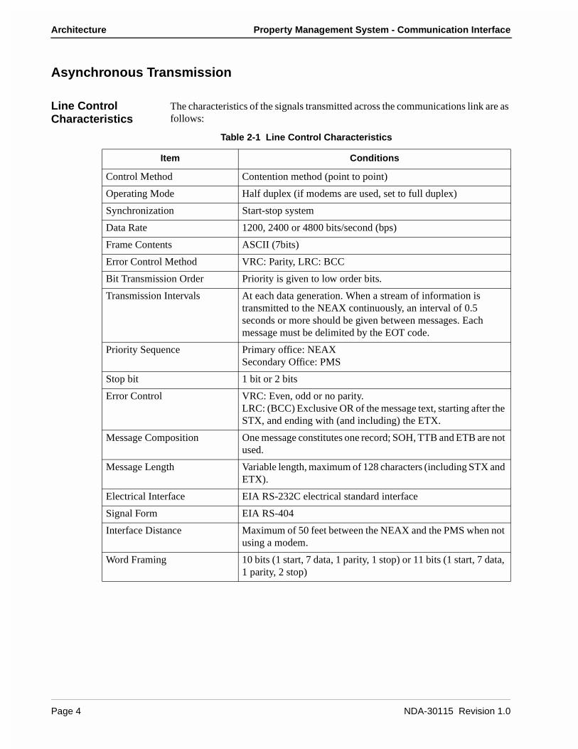
The characteristics of the signals transmitted across the communications link are as follows:
Table 2-1 Line Control Characteristics
Item Conditions
Control Method Contention method (point to point)
Operating Mode Half duplex (if modems are used, set to full duplex)
Synchronization Start-stop system
Data Rate 1200, 2400 or 4800 bits/second (bps)
Frame Contents ASCII (7bits)
Error Control Method VRC: Parity, LRC: BCC
Bit Transmission Order Priority is given to low order bits.
Transmission Intervals At each data generation. When a stream of information is transmitted to the NEAX continuously, an interval of 0.5 seconds or more should be given between messages. Each message must be delimited by the EOT code.
Priority Sequence Primary office: NEAXSecondary Office: PMS
Stop bit 1 bit or 2 bits
Error Control VRC: Even, odd or no parity.LRC: (BCC) Exclusive OR of the message text, starting after the STX, and ending with (and including) the ETX.
Message Composition One message constitutes one record; SOH, TTB and ETB are not used.
Message Length Variable length, maximum of 128 characters (including STX and ETX).
Electrical Interface EIA RS-232C electrical standard interface
Signal Form EIA RS-404
Interface Distance Maximum of 50 feet between the NEAX and the PMS when not using a modem.
Word Framing 10 bits (1 start, 7 data, 1 parity, 1 stop) or 11 bits (1 start, 7 data, 1 parity, 2 stop)
Page 4 NDA-30115 Revision 1.0

Property Management System - Communication Interface Architecture
The control codes used for the message texts are:
Transmission Protocol
Before a message can be sent, a start sequence (also called a selecting sequence) must be sent to urge the receiver to receive the data. Every transmission sequence will begin with the sender sending a start sequence.
The start sequence is a three byte sequence:
Figure 2-1 Start Sequence
Table 2-2 Control Codes
Control CodeHexadecimal
ValueFunction
STX 02 Indicates the start of a block.
ETX 03 Indicates the end of a block.
EOT 04 Indicates the end of transmission of a block or release of the data link by the sender.
ENQ 05 Used to query other party for expected response.
ACK 06 Indicates the positive acknowledgment of an information block or start sequence.
NAK 15 Indicates the negative acknowledgment of an information block or start sequence.
DLE < 10, 3C Indicates the receiver interrupting to ask for sending rights.
DLE : 10, 7C Indicates the receiver interrupting to ask the sender to stop transmission and to release the data link.
DLE ? 10, 3F Used as the negative acknowledgment of block and indicates that the receiver temporarily cannot receive data from the sender.
05H‘1’ ‘!’
0 1 2
SA UA ENQ
NDA-30115 Revision 1.0 Page 5

Architecture Property Management System - Communication Interface
The messages (but not the control codes or start sequence) sent between the NEAX and the PMS must have header and trailing sections as defined in the following format:
Table 2-3 Base Message FormatThe message format breaks down as follows:
• STX -- Start of text block. (One byte - 02H.)
• SA -- System Address. (One byte - ‘1’ [31H].)
• UA -- I/O Unit Address. (One byte - ‘!’ [21H].)
• EI -- Entry Index. (One byte - ‘L’ [4CH].)
• FTC -- Feature Code. (See below.) A list is provided in Appendix C, “Feature Codes”.
• MSC -- Message Counter. This represents the length of the message. The count of characters starts at the FTC field and ends at the last character of the body of the message, not including the ETX. If the ETX character does not immediately follow the character specified by the message counter, an invalid message is assumed.
• FC -- Function Code. This specifies the individual operation and processing for the feature designated by the Feature Code (FTC). A list is provided in Appendix D, “Function Codes”.
• ETX -- End of text block. (One byte - 03H.)
• BCC -- Block Check Code. This is computed by an exclusive OR of the message from the SA to the ETX (inclusive). Detection of an STX starts the computation (but the STX is not included). Detection of an ETX stops the computation (and the ETX is included). (One byte.)
Feature Codes range in value from 00 to FF (hex). These codes define the “Major Category Codes” for service features.
Codes from 80 to FF are used as “Violation Codes”. When a specific message received from the PMS cannot be processed for some reason, 80 (hex) is added to the received Feature Code so that it will be handled as a Violation Code. If the NEAX regards a text as a Violation Code, the system data of the NEAX may be assigned so that a text of this type is returned to the PMS. Therefore, when the PMS has received a Violation Code, provisions should be made for the PMS to print out this violation.
Block Check Code Range
02H ‘1’ 03H xx‘!’ ...
0 1 2 3 4 6 8 9
STX SA UA EI FTC MSC FC Message ETX BCC
Message Count Range
‘L’
Page 6 NDA-30115 Revision 1.0
Property Management System - Communication Interface Architecture
A Violation Code message will be sent to the PMS in the following cases:
• When the message counter does not match the number of characters received.
• When a station number not existing in the NEAX is specified in the message data from the PMS.
• Upon receipt of an invalid Wake Up time (e.g. 25:00).
Transmission Sequence
The sequence of transmitting a message is slightly different for the PMS and NEAX. However, both sequences follow the same outline.
The party which desires to send must first bid for sender rights. This is done by sending the start sequence (see Figure 2-1). Once the start sequence has been sent and acknowledged, that party is now the “sender” and the other party is the “receiver”. (Unless both parties have simultaneously sent a start sequence. If this occurs, the PMS must relinquish sending rights to the NEAX.) The receiver must then respond with an answer control code (ACK, NAK, DLE <, DLE :, DLE ?) before the Sender Timer (see “Sender Timer” on page 10) expires.
If no answer control code is received, the sender will resend the start sequence and again wait for an answer control code.
When an answer control code is received, the sender must respond before the Receiver Timer (see “Receiver Timer” on page 10) expires. If the answer control code is an ACK, the sender must send the message. Again, the receiver must respond with an answer control code before the Sender Timer expires.
To finish the transmission sequence (regardless of its success), the sender must send an End Code (EOT) to release sending rights. Once that is done, both parties may begin the process over again by bidding for the sender rights.
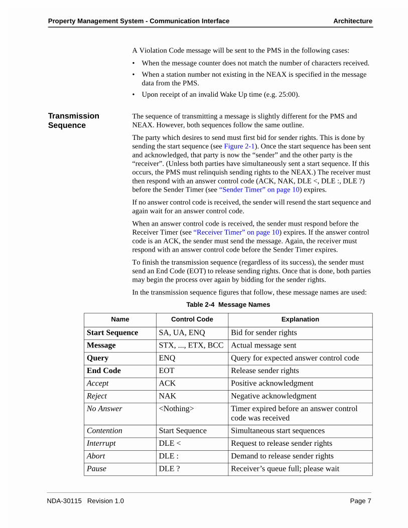
In the transmission sequence figures that follow, these message names are used:
Table 2-4 Message Names
Name Control Code Explanation
Start Sequence SA, UA, ENQ Bid for sender rights
Message STX, ..., ETX, BCC Actual message sent
Query ENQ Query for expected answer control code
End Code EOT Release sender rights
Accept ACK Positive acknowledgment
Reject NAK Negative acknowledgment
No Answer <Nothing> Timer expired before an answer control code was received
Contention Start Sequence Simultaneous start sequences
Interrupt DLE < Request to release sender rights
Abort DLE : Demand to release sender rights
Pause DLE ? Receiver’s queue full; please wait
NDA-30115 Revision 1.0 Page 7

Architecture Property Management System - Communication Interface
From the NEAX to the PMS
Figure 2-2 NEAX to PMS Protocol
StartSequence
Accept
Reject
No Answer
Contention
Interrupt
Abort
Pause
Message Accept
Reject
No Answer
Interrupt
Abort
Pause
EndCode
Wait1 second
Send Receive ReceiveSend Send
retry
quit
retry
retry
retry
retry
quit
quit
quit
quit
1
2
3
4
5
Query
1 - Retry is 3 times; quit on 4th Reject.2 - Retry is 15 times; quit on 16th No Answer.3 - Retry is 3 times; quit on 4th Reject.4 - Retry is 32 times; quit on 33rd No Answer.5 - Retry is 3 times; quit on 4th Pause.
Page 8 NDA-30115 Revision 1.0

Property Management System - Communication Interface Architecture
From the PMS to the NEAX
Figure 2-3 PMS to NEAX protocol
StartSequence
Accept
Reject
Contention
Interrupt
Pause
Message Accept
Reject
No Answer
Interrupt
Pause
EndCode
Wait1 second
Send Receive ReceiveSend Send
retry
quit
Query
Wait1 second
No Answer quit
retry
continue
quit
1
2
3
4
1 - Do not respond. Immediately cease send attempt and
2 - Ignore Interrupt and send message if 8 messages in queue.3 - Retry is 3 times; quit on 4th Reject.4 - Retry is 32 times; quit on 33rd No Answer.
receive message from NEAX.
NDA-30115 Revision 1.0 Page 9
Architecture Property Management System - Communication Interface
Timers The following timers are used to maintain data transmission:
Sender TimerUpon sending a start sequence, message text or query, this timer begins counting and stops counting upon receiving a valid answer control code. This timer is set to one (1) second. If a timeout occurs after the transmission of a start sequence, a start sequence will be resent up to 15 times. If a timeout occurs during the transmission of a message text or query, a query is sent up to 32 times.
Receiver TimerUpon transmission of a positive acknowledgment for a start sequence or a message text, this timer begins counting and stops counting upon receiving a message text or an end code. This timer is set to 35 seconds. If a timeout occurs, the sender loses send rights.
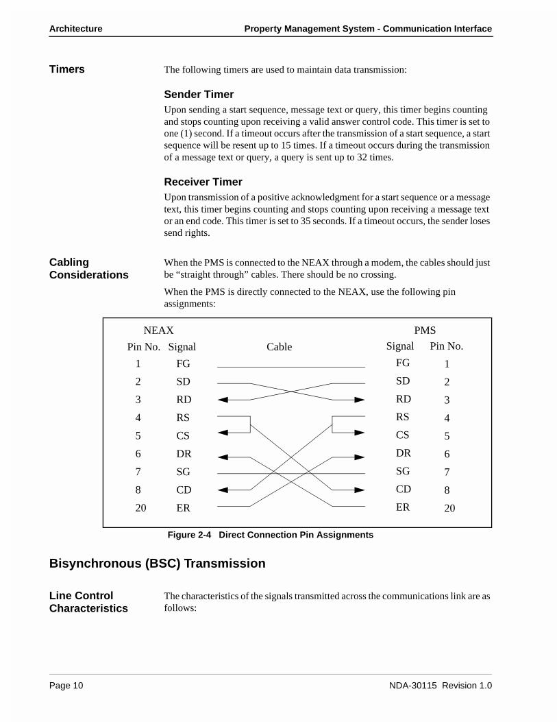
Cabling Considerations
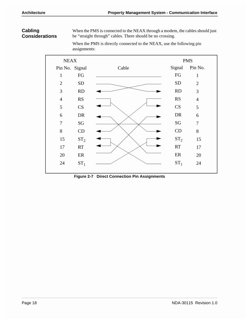
When the PMS is connected to the NEAX through a modem, the cables should just be “straight through” cables. There should be no crossing.
When the PMS is directly connected to the NEAX, use the following pin assignments:
Figure 2-4 Direct Connection Pin Assignments
Bisynchronous (BSC) Transmission
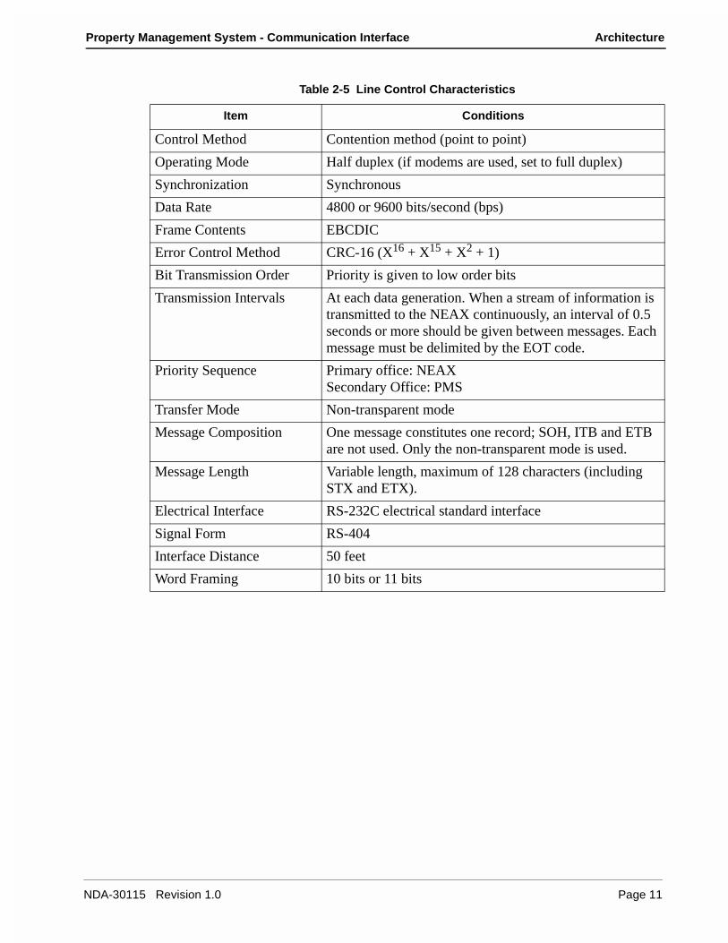
Line Control Characteristics
The characteristics of the signals transmitted across the communications link are as follows:
1 FG
SD
RD
RS
CS
DR
SG
CD
ER
2
3
4
5
6
7
8
20
FG
SD
RD
RS
CS
DR
SG
CD
ER
1
2
3
4
5
6
7
8
20
Pin No. Signal Cable Signal Pin No.
NEAX PMS
Page 10 NDA-30115 Revision 1.0
Property Management System - Communication Interface Architecture
Table 2-5 Line Control Characteristics
Item Conditions
Control Method Contention method (point to point)
Operating Mode Half duplex (if modems are used, set to full duplex)
Synchronization Synchronous
Data Rate 4800 or 9600 bits/second (bps)
Frame Contents EBCDIC
Error Control Method CRC-16 (X16 + X15 + X2 + 1)
Bit Transmission Order Priority is given to low order bits
Transmission Intervals At each data generation. When a stream of information is transmitted to the NEAX continuously, an interval of 0.5 seconds or more should be given between messages. Each message must be delimited by the EOT code.
Priority Sequence Primary office: NEAXSecondary Office: PMS
Transfer Mode Non-transparent mode
Message Composition One message constitutes one record; SOH, ITB and ETB are not used. Only the non-transparent mode is used.
Message Length Variable length, maximum of 128 characters (including STX and ETX).
Electrical Interface RS-232C electrical standard interface
Signal Form RS-404
Interface Distance 50 feet
Word Framing 10 bits or 11 bits
NDA-30115 Revision 1.0 Page 11

Architecture Property Management System - Communication Interface
The control codes used for the message texts are:
Table 2-6 Control Codes
Control CodeHexadecimal
ValueFunction
SYN 32 Synchronization code.
STX 02 Indicates the start of a block.
ETX 03 Indicates the end of a block.
ENQ 2D Used as the start sequence code. It indicates a reception request to the other side and a request to answer an infor-mation block just sent.
EOT 04 Indicates the end of transmission of a block or release of the data link by the sender.
ACK0 10, 70 Used alternately, these indicate the positive acknowledg-ment of an information block or a start sequence.ACK1 10, 61
NAK 3D Indicates the negative acknowledgment of an informa-tion block or a start sequence.
WACK 10, 6B Used as the positive acknowledgment of an information block or start sequence and indicates that the receiver temporarily cannot receive data from the sender.
TTD 02, 2D Indicates that the sender cannot transmit the next infor-mation block after the receipt of the answer to the previ-ous information block sent from the receiver.
RVI 10, 7C Indicates the positive acknowledgment of an information block and asks the sender for sending rights.
PAD-L 55 Indicates the absolute beginning of the entire informa-tion block.
PAD-T FF Indicates the absolute ending of the entire information block.
Page 12 NDA-30115 Revision 1.0

Property Management System - Communication Interface Architecture
Transmission Protocol
The messages sent between the NEAX and the PMS must have header and trailing sections as defined in the following format:
Figure 2-5 Base Message Format
The elements of the message is as follows:
• PAD-L -- The leading pad character. (One byte - 55H.)
• SYN -- Synchronization character. At least three of these should be transmitted. (One byte each - 32H.)
• STX -- Start of text block. (One byte - 02H.)
• Data -- The message data is describe below in Figure 2-6.
• ETX -- End of text block. (One byte - 03H.)
• CRC-- Cyclic Redundancy Check. This is computed by an exclusive OR of the message from the SA to the ETX (inclusive). Detection of an STX starts the computation (but the STX is not included). Detection of an ETX stops the computation (and the ETX is included). (One byte.)
• PAD-T -- The trailing pad character. (One byte - FFH.)The message data is defined as follow:
Figure 2-6 Message Data Format
Cyclic Redundancy Check Area
02H 03H xx
STX Data ETX CRC PAD-T
FFH32H55H 32H 32H
PAD-LSYN SYN SYN
02H ‘1’ 03H‘!’ ...
STX SA UA EI FTC MSC FC Message ETX
Message Count Range
‘L’
NDA-30115 Revision 1.0 Page 13

Architecture Property Management System - Communication Interface
The message format breaks down as follows:
• STX -- Start of text block. (One byte - 02H.)
• SA -- System Address. (One byte - ‘1’ [31H].)
• UA -- I/O Unit Address. (One byte - ‘!’ [21H].)
• EI -- Entry Index. (One byte - ‘L’ [4CH].)
• FTC -- Feature Code. (See below.) A list is provided in Appendix C, “Feature Codes”.
• MSC -- Message Counter. This represents the length of the message. The count of characters starts at the FTC field and ends at the last character of the body of them message, not including the ETX. If the ETX character does not immediately follow the character specified by the message counter, an invalid message is assumed.
• FC -- Function Code. This specifies the individual operation and processing for the feature designated by the Feature Code (FTC). A list is provided in Appendix D, “Function Codes”.
• ETX -- End of text block. (One byte - 03H.)
Feature Codes range in value from 00 to FF (hex). These codes define the “Major Category Codes” for service features.
Codes from 80 to FF are used as “Violation Codes”. When a specific message received from the PMS cannot be processed for some reason, 80 (hex) is added to the received Feature Code so that it will be handled as a Violation Code. If the NEAX regards a text as a Violation Code, the system data of the NEAX may be assigned so that a text of this type is returned to the PMS. Therefore, when the PMS has received a Violation Code, provisions should be made for the PMS to print out this violation.
A Violation Code message will be sent to the PMS in the following cases:
• When the message counter does not match the number of characters received.
• When a station number not existing in the NEAX is specified in the message data from the PMS.
• Upon receipt of an invalid Wake Up time (e.g. 25:00).
Page 14 NDA-30115 Revision 1.0
Property Management System - Communication Interface Architecture
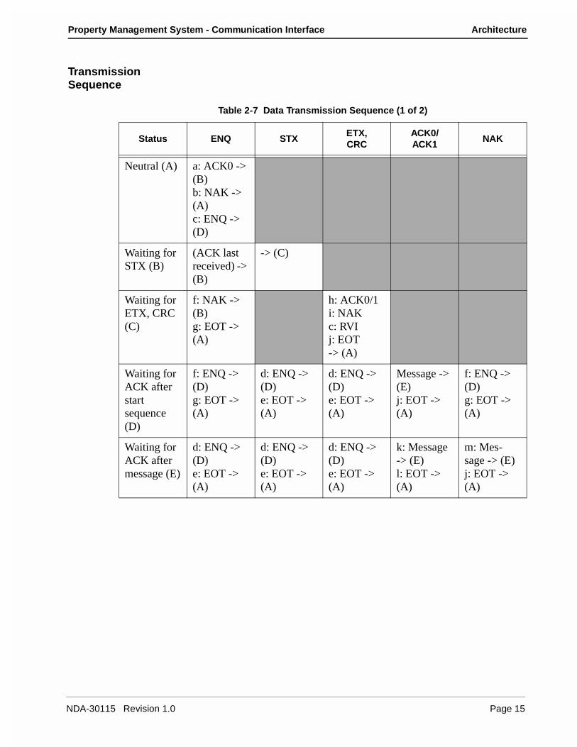
Transmission Sequence
Table 2-7 Data Transmission Sequence (1 of 2)
Status ENQ STXETX,CRC
ACK0/ACK1
NAK
Neutral (A) a: ACK0 -> (B)b: NAK -> (A)c: ENQ -> (D)
Waiting for STX (B)
(ACK last received) -> (B)
-> (C)
Waiting for ETX, CRC (C)
f: NAK -> (B)g: EOT -> (A)
h: ACK0/1i: NAKc: RVIj: EOT-> (A)
Waiting for ACK after start sequence (D)
f: ENQ -> (D)g: EOT -> (A)
d: ENQ -> (D)e: EOT -> (A)
d: ENQ -> (D)e: EOT -> (A)
Message -> (E)j: EOT -> (A)
f: ENQ -> (D)g: EOT -> (A)
Waiting for ACK after message (E)
d: ENQ -> (D)e: EOT -> (A)
d: ENQ -> (D)e: EOT -> (A)
d: ENQ -> (D)e: EOT -> (A)
k: Message -> (E)l: EOT -> (A)
m: Mes-sage -> (E)j: EOT -> (A)
NDA-30115 Revision 1.0 Page 15
Architecture Property Management System - Communication Interface
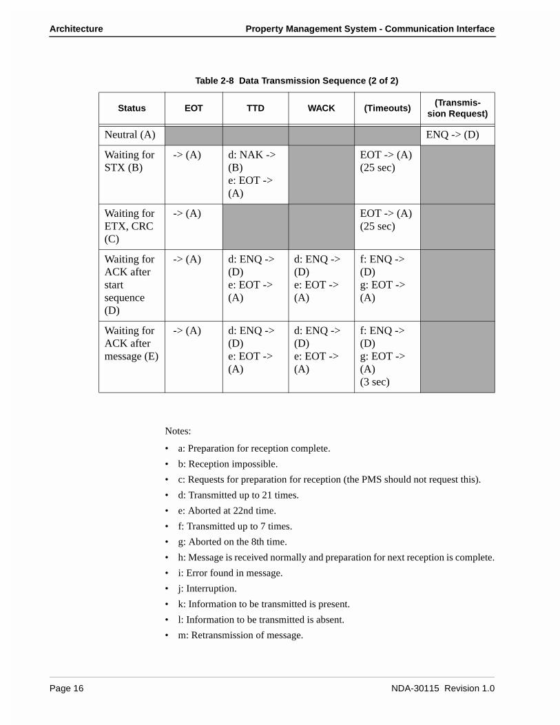
Notes:
• a: Preparation for reception complete.
• b: Reception impossible.
• c: Requests for preparation for reception (the PMS should not request this).
• d: Transmitted up to 21 times.
• e: Aborted at 22nd time.
• f: Transmitted up to 7 times.
• g: Aborted on the 8th time.
• h: Message is received normally and preparation for next reception is complete.
• i: Error found in message.
• j: Interruption.
• k: Information to be transmitted is present.
• l: Information to be transmitted is absent.
• m: Retransmission of message.
Table 2-8 Data Transmission Sequence (2 of 2)
Status EOT TTD WACK (Timeouts)(Transmis-
sion Request)
Neutral (A) ENQ -> (D)
Waiting for STX (B)
-> (A) d: NAK -> (B)e: EOT -> (A)
EOT -> (A)(25 sec)
Waiting for ETX, CRC (C)
-> (A) EOT -> (A)(25 sec)
Waiting for ACK after start sequence (D)
-> (A) d: ENQ -> (D)e: EOT -> (A)
d: ENQ -> (D)e: EOT -> (A)
f: ENQ -> (D)g: EOT -> (A)
Waiting for ACK after message (E)
-> (A) d: ENQ -> (D)e: EOT -> (A)
d: ENQ -> (D)e: EOT -> (A)
f: ENQ -> (D)g: EOT -> (A)(3 sec)
Page 16 NDA-30115 Revision 1.0

Property Management System - Communication Interface Architecture
Timers and Counters
Retransmission Counts
Timer Values
Table 2-9 Retransmission Counts
Meaning Count
The number of retransmissions of the start sequence when there is no answer after transmitting the start sequence.
7
The number of retransmissions of the start sequence when NAK is received after transmitting the start sequence.
7
The number of transmitting ENQs when WACK is received after the transmission of an information block
15
The number of transmitting ENQs when there is no answer after the transmission of an information block. (3 second intervals)
7
Table 2-10 Timer Values
Party Starting ConditionTimer value(seconds)
NEAX Waiting for a start sequence answer. 1
Waiting for STX after transmitting the start sequence ACK. 20
Waiting for data reception complete (waiting for ETX, CRC). 20
Waiting for an answer after the transmission of a message. 1
PMS Waiting for a start sequence answer. 3
Waiting for STX after transmitting the start sequence ACK. 25
Waiting for data reception complete (waiting for ETX, CRC). 25
Waiting for an answer after the transmission of a message. 3
NDA-30115 Revision 1.0 Page 17
Architecture Property Management System - Communication Interface
Cabling Considerations
When the PMS is connected to the NEAX through a modem, the cables should just be “straight through” cables. There should be no crossing.
When the PMS is directly connected to the NEAX, use the following pin assignments:
Figure 2-7 Direct Connection Pin Assignments
1 FG
SD
RD
RS
CS
DR
SG
CD
ST2
RT
ER
ST1
2
3
4
5
6
7
8
15
17
20
24
FG
SD
RD
RS
CS
DR
SG
CD
ST2
RT
ER
ST1
1
2
3
4
5
6
7
8
15
17
20
24
Pin No. Signal Cable Signal Pin No.
NEAX PMS
Page 18 NDA-30115 Revision 1.0

Property Management System - Communication Interface Message Descriptions
Chapter 3 Message Descriptions
There are several message groups:
• Data Link Maintenance Messages
• Maid Status
• Message Waiting Lamp Control
• Restriction Control
• Check In/Check Out (Model 60)
• Check In/Check Out (Model 90)
• Wake Up/Group Announcement
• Room Move/Swap/Copy (Model 60)
• Room Data Change
• Extension Report
• Room Recovery (Model 60)
• Room Recovery (Model 90)
• Direct Data Entry (Model 90)
• Extension ConnectionEach message group will be described briefly in the following sections.
The NEAX equates rooms with extensions, one extension per room. The exception to this is the suite room feature. When this feature is activated in the NEAX, a primary extension represents a group of extensions in one or more rooms. For a suite room, the PMS should reference only the primary extension in its messages to the NEAX. All associated extensions will inherit the attributes of the primary extension and should effectively be ignored by the PMS.
Data Link Maintenance
These are the messages used by the PMS and NEAX to maintain communication.
The PMS must regularly send Nop Test messages with an interval of no more than 60 seconds, and no less than 500 milliseconds, between each message. The NEAX will immediately respond with either a Nop Test Normal Answer, under normal conditions, or a Nop Test Recover Answer, if a database recovery for the NEAX is needed.
• Nop Test Normal Answer -- Whenever a Nop Test message is sent by the PMS, the NEAX responds by sending this message, unless the NEAX has just finished an error recovery.
• Nop Test Recover Answer -- If the NEAX has been performing an error recovery, this message is sent in response to the Nop Test in the place of the Nop Test Normal Answer message.
NDA-30115 Revision 1.0 Page 19
Message Descriptions Property Management System - Communication Interface
• Recovery Start Report -- After receiving the Nop Test Recover Answer message, the PMS must download NEAX database information (see “Room Recovery (Model 60)” on page 27 and “Room Recovery (Model 90)” on page 28). This message notifies the NEAX of the incoming download.
• Recovery End Report -- Reports to the NEAX that the PMS database download is complete.
• Data Link Release Request -- Used by either system to request a temporary release of the data link.
• Data Link Release Confirmation -- Reply to the above message to acknowledge data link release request.
• Extension Number Request -- Used by the PMS to request the current status of extension numbers.
• Nop Test -- Under the standard protocol the PMS must send this message at least every 60 seconds, but not less than 500 milliseconds, to demonstrate that communication has been maintained.
Data Link Failure Either system may recognize a loss of communication by one or more of the following events:
• Lack of system traffic for a 60 second interval: the Nop Test message from the PMS and the Nop Test Answer message (either Normal or Recover) from the NEAX insure that at least one message should be received less than every 60 seconds.
• Detection of hardware problems within the physical data. Note that the NEAX will put EIA pin number 6 (Data Set Ready) into the off state, indicating data set not ready, when the data link has been effectively turned off in the NEAX, either for maintenance or because of repeated, excessive errors.
• Excessive protocol errors (NAK’ed transmission, ENQ’s with no ACK/NAK response).
• Other conditions, such as unavailability of buffers or queuing capability, which result in an implied status change message which cannot be communicated to the other system.
• Release of the data link requested and confirmed.A data link failure will necessitate a database room exchange recovery procedure only if any implied status change cannot be communicated to the other system and cannot be queued for later transmission. If no messages have been lost, and can instead be retransmitted, no database recovery is necessary.
Page 20 NDA-30115 Revision 1.0
Property Management System - Communication Interface Message Descriptions
Release for Maintenance
Either system may request a temporary release of the data link for maintenance purposes by transmitting a Data Link Release Request message to the other system. The receiving system will perform any necessary processing and return the Data Link Release Confirmation message as soon as possible.
During the NEAX maintenance, the PMS may continue to send Nop Test messages, provided that EIA pin 6 (Data Set Ready) from the NEAX is in the “on” condition. The NEAX will turn on the EIA pin 6 “on” and respond to Nop Test messages when maintenance is completed.
While the data link is release on request of the PMS, the NEAX will continue to attempt to read Nop Test messages from the PMS. The PMS may set EIA pin 20 (Data Terminal Ready) to the “off” condition to indicate that reading should not be attempted.
When EIA pin 20 is in the “on” state and a Nop Test message is received from the PMS, the NEAX will assume that PMS maintenance has ended and that communication can be resumed.
NEAX Operations During Loss of Communication
The NEAX will continue to support the basic telecommunications functions if the data link or PMS become unavailable. Upon detection of a data link failure, the NEAX will automatically switch to the “Link Failed Mode” to perform the following tasks:
• Enable Check In and Check Out on the Attendant Console and Front Desk Terminal.
• Continue support of Message Waiting and/or Controlled Restriction if both features are active in the NEAX.
Recovery from Loss of Communication
In the event of a PMS failure, it is assumed that Check In and Check Out must be done manually and entered into the PMS system at a later time. The PMS should not resume transmission of the Nop Test message and attempt to reestablish communication until the database has been brought up to date. This prevents the transmission of incorrect data prematurely through the database recovery procedure.
In cases where the PMS has remained operational during a data link failure, the PMS will continue to attempt sending Nop Test messages. A Nop Test Answer message (either Normal or Recover) from the NEAX will indicate that communication has been reestablished.
A Nop Test Normal Answer message indicates that the NEAX has had no status change during the data link failure period and has automatically switched back to the normal operating mode of an active data link.
A Nop Test Recover Answer message indicates that the NEAX has failed and that status memory has been initialized for each room with the following:
• Room Status is Occupied (Checked In),
• Controlled Restriction Level is set to the preassigned restriction,
• Message Waiting Lamps are off,
• Wake Up times are cleared.
NDA-30115 Revision 1.0 Page 21

Message Descriptions Property Management System - Communication Interface
Maid Status
These messages are used by the NEAX to communicate the actions of the cleaning personnel. If the message is designated “Model 90” then that message is only used by the Model 90 version. The other messages are used by both versions.
• Cleaning Start (Guest)
• Cleaning End (Guest)
• Inspection End (Guest)
• Out of Order (Guest)
• Cleaning Start (Administration)
• Cleaning End (Administration)
• Inspection End (Administration)
• Guest Room 1 (Model 90)
• Guest Room 2 (Model 90)
• Guest Room 3 (Model 90)
• Guest Room 4 (Model 90)
• Guest Room 5 (Model 90)
• Guest Room 6 (Model 90)
• Guest Room 7 (Model 90)
Note: This message was not previously defined in NEAX2400 IMS Hotel System PMS Interface Specification.
• Negative Answer (Model 90)
• Positive Answer (Model 90)
• Administration 1 (Model 90)
• Administration 2 (Model 90)
• Administration 3 (Model 90)
• Administration 4 (Model 90)For an expanded explanation of how the NEAX treats maid status information, refer to Appendix A, “Room Status”.
Page 22 NDA-30115 Revision 1.0
Property Management System - Communication Interface Message Descriptions
Message Waiting Lamp Control
These messages are used to control the message waiting lamp on an extension. The message waiting lamp is used to notify a guest about the existence of text messages. If the message is designated “Model 90” then that message is only used by the Model 90 version. The other messages are used by both versions.
When the NEAX is configured to use the suite room feature, the primary extension represents all extensions in that suite. Therefore, a message set to the primary extension controls the message waiting lamps on all extensions in that suite.
• MWL On -- This message is sent by the PMS to turn on a message waiting lamp.
• MWL Off -- This message is sent by the PMS to turn off a message waiting lamp.
• MWL On -- This message is sent by the NEAX to notify the PMS that a message waiting lamp has been turned on.
• MWL Off -- This message is sent by the NEAX to notify the PMS that a message waiting lamp has been turned off.
• MWL Status -- This message is sent by the PMS. (Model 90)
• MWL On (FDT) -- This message is sent by the NEAX to notify the PMS that a message waiting lamp has been turned on by the front desk. (Model 90)
• MWL Off (FDT) -- This message is sent by the NEAX to notify the PMS that a message waiting lamp has been turned off by the front desk. (Model 90)
Restriction Control
There are two messages. They are identical except that one is originated by the PMS, the other by the NEAX. Each message simply transmits the restriction code. Both the Model 60 and the Model 90 version use these messages.
Check In/Check Out (Model 60)
These messages do not represent unique features as such, but are a convenient tool for activating a sequence of functions commonly performed when a guest checks in or out of a room. With one exception, all of these messages are used exclusively for Model 60. The sole exception is Check Out Outgoing Call Report, which is also used by Model 90.
When the NEAX is configured to use the suite room feature, the primary extension represents all extensions in that suite. Therefore, a message set to the primary extension controls the status of all extensions in that suite.
• Check In 1 -- Sets the Room Status to Stay and cancels Room Cut-Off. This message is sent by the PMS. This message should not be used. Use Check In 3 instead.
• Check Out -- Sets the Room Status to Out and sets Room Cut-Off. This message is sent by the PMS.
NDA-30115 Revision 1.0 Page 23

Message Descriptions Property Management System - Communication Interface
• Check Out Message Waiting Lamp Off Report -- This message is sent by the NEAX to report that the Message Category “Front” of that specific guest room is Off.
• Check Out Message Waiting Lamp On Report -- This message is sent by the NEAX to report that the Message Category “Front” of that specific guest room is On.
• Check In 2 -- Same as Check In 1, but also sets the Language and Room Stay. This message should not be used. Use Check In 3 instead.
• Check In 3 -- Same as Check In 2, but also sets the Guest Name and Group Number.
• Check Out Outgoing Call Report -- The NEAX sends this message if, after receiving a check out message from the PMS, it determines that the guest extension is engaged in an outgoing call.
• Check Out Message Waiting Report -- This message is generated by the NEAX to report the status of waiting messages.
Check In/Check Out (Model 90)
These messages do not represent unique features as such, but are a convenient tool for activating a sequence of functions commonly performed when a guest checks in or out of a room. All of these messages are used exclusively for Model 90. There is also the addition of the Check Out Outgoing Call Report message which is technically a Model 60 message, but is available for Model 90.
When the NEAX is configured to use the suite room feature, the primary extension represents all extensions in that suite. Therefore, a message set to the primary extension controls the status of all extensions in that suite.
• Check In -- This message is sent by the PMS to notify the NEAX of a check in. This cancels Room Cut-Off.
• Check Out -- This message is sent by the PMS to notify the NEAX of a check out.
• Check In Cancellation -- This message is sent by the PMS. It cancels a previously sent check in message. The room status is set to “Vacant.”
• Check Out Cancellation -- This message is sent by the PMS. It cancels a previously sent check out message. Under some circumstances the NEAX may fail to perform this function which means that the guest must be checked in again.
• Room Change -- This message is sent by the PMS to notify the NEAX of a guest room change.
• Provisional Check In -- This is a provisional check in message generated by the NEAX. The room status is set to “Stay” and Room Cut-Off is cancelled.
• Provisional Check Out -- This is a provisional check out message generated by the NEAX. If maid status is not performed, room status is set to “Vacant;” if maid status is performed, room status is set to “Out.”
• Check Out Message Waiting Report -- This message is generated by the NEAX upon receiving a check out message to report the status of waiting messages.
Page 24 NDA-30115 Revision 1.0

Property Management System - Communication Interface Message Descriptions
Wake Up/Group Announcement
These messages allow for the management of wake up calls and group announcements. Both the Model 60 and the Model 90 version use these messages.
• Wake Up Setting (NEAX) -- This message is sent by the NEAX to notify the PMS that a wake up call has been set.
• Wake Up Cancellation (NEAX) -- This message is sent by the NEAX to notify the PMS that a wake up call has been cancelled.
• Wake Up Execution Result -- This message is sent by the NEAX to report the results of the wake up call.
• Wake Up Setting(PMS) -- This message is sent by the PMS to set a wake up call.
• Wake Up Cancellation (PMS) -- This message is sent by the PMS to cancel a wake up call.
• Group Announcement Setting (NEAX) -- This message is sent by the NEAX to notify the PMS that a group announcement has been set.
• Group Announcement Cancellation (NEAX) -- This message is sent by the NEAX to notify the PMS that a group announcement has been cancelled.
• Group Announcement Execution Result -- This message is sent by the NEAX to report the results of a group announcement.
• Group Announcement Setting (PMS) -- This message is sent by the PMS to set a group announcement.
• Group Announcement Cancellation (PMS) -- This message is sent by the PMS to cancel a group announcement.
Room Move/Swap/Copy (Model 60)
These messages are used to transfer room information. All of these messages are used exclusively for Model 60. The messages are:
• Room Move -- This takes the data for one room and moves it to another room. This will leave the second extension’s maid status unchanged, cancels Room Cut-Off and sets all other data to that of the first extension. The first extension’s maid status is set to ‘1’, Room Cut-Off is set, Do Not Disturb and Message Waiting is reset, Wake Up is cancelled, Language is set to “Undefined” and Guest Name and Group Number are cleared.
• Room Swap -- This takes the data for one room and moves it to another room, while taking the other room’s data and moving it to the first room.
• Room Copy -- This exactly copies the data for one room to another room without changing the data for the first room. The PMS should take care to be consistent in the manner in which this message is used. If the PMS sends a Room Copy message after check in, it should send a Room Copy message after check out.
NDA-30115 Revision 1.0 Page 25
Message Descriptions Property Management System - Communication Interface
Room Data Change
These messages are used to change the room information while a guest is still checked in. Messages designated “Model 60” are only used by the Model 60 version; “Model 90” are only used by the Model 90 version. Messages with neither designation may be used by either version. The messages are as follows:
• Room Data Change 60 -- This is used to change room data after check in. This message is sent by the PMS. (Model 60)
• Group Formation -- This is used when adding a guest to a group or changing a guest’s group after check in. This message is sent by the PMS.
• Group Cancellation -- This is used to remove a guest from a group after check in. This message is sent by the PMS.
• Reservation Setting -- This is used to set reservation for a guest room. The reservation information is cleared by check in processing or when the room status becomes “Vacant” or “Out of Order”. (Model 60)
• Reservation Cancellation -- This cancels guest room reservation. (Model 60)
• Guest Name Change -- This is used to change the guest name after check in. This message is sent by the PMS. (Model 60)
• Room Data Change 90 -- This is used to change room data after check in. This message is sent by the PMS. (Model 90)
• Room Status Change -- This is used to change the room status and/or the cleaning status of the room after check in. This message is sent by the PMS. (Model 90)
• Room Key Status Change -- This is used to change the room key status after check in. This message is sent by the PMS. (Model 90)
Extension Report
These messages are used by the NEAX to report to the PMS when an extension has been removed or a new extension has been added. Both the Model 60 and the Model 90 version use these messages.
Page 26 NDA-30115 Revision 1.0

Property Management System - Communication Interface Message Descriptions
Room Recovery (Model 60)
These messages are used by the PMS to update the database in the Model 60 version. These messages will usually only be sent if requested by the NEAX using the Nop Test Recover Answer message. However, the PMS may, if necessary, initiate a recovery with a direct request from the NEAX.
Before any recovery messages can be sent, the PMS must first send a Recovery Start Report message. After all information about rooms has been sent by recovery messages, a Recovery End Report message must be sent. Both of these messages are defined in the Data Link Maintenance section.
The recovery messages are grouped into three sets of four messages. Within each set of four messages, the format of the messages is identical, except for the Function Codes, which specify the message. Each set of messages contains more fields (and can therefore convey more information) than the preceding set.
Each set of four messages is composed of two pairs of messages. The PMS must use the same set of recovery messages during the recovery period. The first pair of messages is used when the PMS, in normal operation (i.e. not error recovery), needs to update the information on a given extension. The second pair of messages is used during recovery. This pair will only be used in response to the NEAX sending a Nop Test Recover Answer or Recovery Request message.
The first message (of either pair) is used by the PMS as an update/ request for information on an extension. If a field contains a valid entry, the NEAX database is updated; if the field is entirely filled with NULL (00H) characters, it is a request for the NEAX to send the value from the NEAX database. The second message is the response from the NEAX to the PMS.
• Room Image Set 1 -- Contains the following fields: Extension, Vacancy, MWL and Restriction Level.
• Room Image Set 2 -- In addition to the above fields, the following are added: Room Stay, Reserve, Language, Cleaning Status and Wake Up.
• Room Image Set 3 -- In addition to the above fields, Group Number and Group Announcement are added.
NDA-30115 Revision 1.0 Page 27
Message Descriptions Property Management System - Communication Interface
Room Recovery (Model 90)
These messages are used by the PMS to update the database in the Model 90 version after a failure recovery. These messages will usually only be sent if requested by the NEAX using the Nop Test Recover Answer message. However, the PMS may, if necessary, initiate a recovery with a direct request from the NEAX.
Before any recovery messages can be sent, the PMS must first send a Recovery Start Report message. After all information about rooms has been sent by recovery messages, a Recovery End Report message must be sent. Both of these messages are defined in the Data Link Maintenance section.
• Room Data Report -- Once Recovery has been requested by the NEAX, the PMS uses this message to report the data for each room.
• Guest Room Secretary Telephone -- This message is used to recover data for a secretary telephone.
• Connecting Room -- If any rooms are connecting, this message is used to establish the relationship.
• Message Status Report -- This reports the status of the Message Waiting Lamp.
• Wake Up -- Any wake up data is reported by this message.
Direct Data Entry (Model 90)
These messages are used to send numeric information from the NEAX to the PMS. An employee provides this information by entering an access code at a guest room telephone. Then the NEAX captures all numeric input following the access code and sends the digits to the PMS.
The NEAX expects to receive a response to this message within 30 seconds. If no response is sent, or a Negative Answer is received, a reorder tone will be heard. If a Positive Answer is received, the NEAX will recognize that the information has been entered successfully and the service set tone will be heard.
• Direct Data Entry -- This message is sent by the NEAX and contains the numeric information entered at the guest room telephone.
• Direct Data Entry Negative Answer -- This message is sent by the PMS to notify the NEAX that the numeric data sent from the specified guest room telephone has been rejected.
• Direct Data Entry Positive Answer -- This message is sent by the PMS to notify the NEAX that the numeric data sent from the specified guest room telephone has been accepted.
Page 28 NDA-30115 Revision 1.0
Property Management System - Communication Interface Message Descriptions
Extension Connection
These messages are used to associate extensions. This association will be either in the form of a Boss/Secretary or of a Master/Secondary. In either case, both of the rooms to be connected must be checked in. There may only be one Secretary for each Boss, but a Secretary may be assigned to multiple Bosses. A Master and Secondary may only be assigned on a one to one basis. The effect of the Boss/Secretary association is that whenever the Boss extension is called, only the Secretary extension will ring. In the case of Master/Secondary, whenever the Master extension is called, both the Master extension and the Secondary extension will ring. All of these messages are used exclusively for Model 90.
• Guest Room Secretary Telephone (PMS) -- This message is sent by the PMS to set or cancel the guest room telephone.
• Guest Room Secretary Telephone (NEAX) -- This message is sent by the NEAX to notify the PMS that a guest room secretary telephone has been set or cancelled.
• Connecting Room Set -- This message is sent by the PMS to connect a main room with a sub room. This message should only be sent after both rooms have been checked in.
• Connecting Room Cancel -- This message is sent by the PMS to cancel a room connection.
NDA-30115 Revision 1.0 Page 29
Message Descriptions Property Management System - Communication Interface
This Page Left Blank.
Page 30 NDA-30115 Revision 1.0

Property Management System - Communication Interface Message Formats
Chapter 4 Message Formats
All messages sent between the NEAX and the PMS must have header and trailing sections as defined in the following format:
Figure 4-1 Base Message Format
The message format breaks down as follows:
• STX -- Start of text block. (One byte - 02H.)
• SA -- System Address. (One byte - ‘1’ [31H].)
• UA -- I/O Unit Address. (One byte - ‘!’ [21H].)
• EI -- Entry Index. (One byte - ‘L’ [4CH].)
• FTC -- Feature Code. Used in conjunction with the Function Code to uniquely identify a message. A list of values are included in Appendix C, “Feature Codes”. (Two bytes.)
• MSC -- Message Count. This is the number of bytes from the FTC character up to the character before the ETX. (Two bytes.)
• FC -- Function Code. This entry is dependent on the FTC entry. A list of values are included in Appendix D, “Function Codes”. (One byte.)
• ETX -- End of text block. (One byte - 03H.)
• BCC -- Block Check Code. This is computed by an exclusive OR of the message from the SA to the ETX (inclusive). Detection of an STX starts the computation (but the STX is not included). Detection of an ETX stops the computation (and the ETX is included). (One byte.)
Note 1: Unless otherwise noted, if the data to be stored in a message field has fewer char-acters than the size of the field, all data must be left justified and the remaining characters must be filled with space (20H) characters.
Note 2: In the message diagrams, the STX, SA, UA, EI, FTC, MSC, FC and ETX fields will show the actual entries needed. The remaining fields will have the name of the field in the box and the length of the field below. For all fields, the beginning byte number is listed on the top of the field.
Block Check Code Range
02H ‘1’ 03H xx‘!’
** Options defined below
...
0 1 2 3 4 6 8 9
STX SA UA EI FTC MSC FC Message ETX BCC
** ** **
Message Count Range
‘L’
NDA-30115 Revision 1.0 Page 31

Message Formats Property Management System - Communication Interface
Note 3: In the case of messages that are almost identical, the FC will be marked with “**”. Also, differing FTC values will be marked with “*”. The final message is then constructed by simply inserting the desired FC value (and, if necessary, the desired FTC value).
All messages in this section have been previously defined in NEAX2400 IMS Hotel System PMS Interface Specification (except for one Maid Status message, which is so noted). The versions supported are Model 60 and Model 90; Model 120 messages are not supported. Any message that is intended to work with only one version is so designated; any message that is intended to work with both has no special designation.
The Feature Codes used are as follows:
• 70 -- Data Link Maintenance
• 11, 12, 51, 52 -- Maid Status
• 13, 53 -- Message Waiting Lamp Control
• 15 -- Restriction Control
• 16 -- Check-In/Out (Model 60)
• 56 -- Check-In/Out (Model 90)
• 19 -- Wake Up/Group Announcement
• 20 -- Room Move/Swap/Copy (Model 60)
• 21, 61 -- Room Data Change
• 17 -- Extension Report
• 17 -- Room Recovery (Model 60)
• 57 -- Room Recovery (Model 90)
• 59 -- Direct Data Entry (Model 90)
• 62 -- Extension Connection
Data Link Maintenance
These messages are used by the NEAX and the PMS to maintain the data link between them. The messages are as follows:
• 70-0 -- Nop Test Normal Answer (Sent by NEAX)
• 70-2 -- Nop Test Recover Answer (Sent by NEAX)
• 70-3 -- Recovery Start Report (Sent by PMS)
• 70-4 -- Recovery End Report (Sent by PMS)
• 70-5 -- Data Link Release Request (Sent by PMS and NEAX)
• 70-6 -- Data Link Release Confirmation. (Sent by PMS and NEAX)
• 70-8 -- Extension Number Request (Sent by PMS)
• 70-F -- Nop Test (Sent by PMS)
Page 32 NDA-30115 Revision 1.0

Property Management System - Communication Interface Message Formats
The format of all Data Link Maintenance messages are exactly as follows:
Figure 4-2 Data Link Maintenance Message Format
The message format breaks down as follows:
• FC -- Function Codes that use this message format are: (FTC-FC)
• 70-0 -- Nop Test Normal Answer
• 70-2 -- Nop Test Recover Answer
• 70-3 -- Recovery Start Report
• 70-4 -- Recovery End Report
• 70-5 -- Data Link Release Request
• 70-6 -- Data Link Release Confirmation
• 70-8 -- Extension Number Request
• 70-F -- Nop Test
• Blank -- Field consists of two space (20H) characters.
Maid Status
This message group uses multiple Feature Codes. The code pairs are as follows (first number is the Feature Code, second number is the Function Code):
• 11-1 -- Cleaning Start (Guest)
• 11-2 -- Cleaning End (Guest)
• 11-3 -- Inspection End (Guest)
• 11-4 -- Out of Order (Guest)
• 12-1 -- Cleaning Start (Administration)
• 12-2 -- Cleaning End (Administration)
• 12-3 -- Inspection End (Administration)
• 51-1 -- Guest Room 1 (Model 90)
• 51-2 -- Guest Room 2 (Model 90)
• 51-3 -- Guest Room 3 (Model 90)
• 51-4 -- Guest Room 4 (Model 90)
• 51-5 -- Guest Room 5 (Model 90)
• 51-6 -- Guest Room 6 (Model 90)
** Multiple Function Codes use this message. See below.
0 1 2 3 4 6 8 9 11 12
STX SA UA EI FTC MSC FC 2
‘7’ ‘0’ ‘0’ ‘7’ ** Blank02H ‘1’ ‘!’ ‘L’ 03H xx
ETX BCC
NDA-30115 Revision 1.0 Page 33
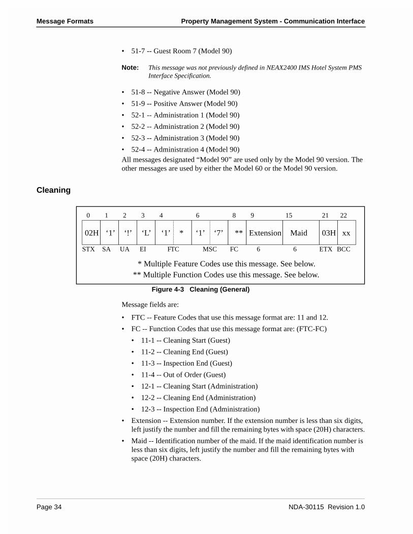
Message Formats Property Management System - Communication Interface
• 51-7 -- Guest Room 7 (Model 90)
Note: This message was not previously defined in NEAX2400 IMS Hotel System PMS Interface Specification.
• 51-8 -- Negative Answer (Model 90)
• 51-9 -- Positive Answer (Model 90)
• 52-1 -- Administration 1 (Model 90)
• 52-2 -- Administration 2 (Model 90)
• 52-3 -- Administration 3 (Model 90)
• 52-4 -- Administration 4 (Model 90)All messages designated “Model 90” are used only by the Model 90 version. The other messages are used by either the Model 60 or the Model 90 version.
Cleaning
Figure 4-3 Cleaning (General)
Message fields are:
• FTC -- Feature Codes that use this message format are: 11 and 12.
• FC -- Function Codes that use this message format are: (FTC-FC)
• 11-1 -- Cleaning Start (Guest)
• 11-2 -- Cleaning End (Guest)
• 11-3 -- Inspection End (Guest)
• 11-4 -- Out of Order (Guest)
• 12-1 -- Cleaning Start (Administration)
• 12-2 -- Cleaning End (Administration)
• 12-3 -- Inspection End (Administration)
• Extension -- Extension number. If the extension number is less than six digits, left justify the number and fill the remaining bytes with space (20H) characters.
• Maid -- Identification number of the maid. If the maid identification number is less than six digits, left justify the number and fill the remaining bytes with space (20H) characters.
‘1’ * ‘1’ ‘7’ ** Extension Maid
** Multiple Function Codes use this message. See below.* Multiple Feature Codes use this message. See below.
0 1 2 3 4 6 8 9 15 21 22
STX SA UA EI FTC MSC FC 6 6
02H ‘1’ ‘!’ ‘L’ 03H xx
ETX BCC
Page 34 NDA-30115 Revision 1.0

Property Management System - Communication Interface Message Formats
Guest Room
Figure 4-4 Guest Room (General)
Message fields are:
• FC -- Function Codes that use this message format are: (FTC-FC)
• 51-1 -- Guest Room 1 (Model 90)
• 51-2 -- Guest Room 2 (Model 90)
• 51-3 -- Guest Room 3 (Model 90)
• 51-4 -- Guest Room 4 (Model 90)
• 51-5 -- Guest Room 5 (Model 90)
• 51-6 -- Guest Room 6 (Model 90)
• 51-7 -- Guest Room 7 (Model 90)
Note: This message was not previously defined in NEAX2400 IMS Hotel System PMS Interface Specification.
• Extension -- Extension number. If the extension number is less than six digits, left justify the number and fill the remaining bytes with space (20H) characters.
• Maid -- Identification number of the maid. If the maid identification number is less than six digits, left justify the number and fill the remaining bytes with space (20H) characters.
• LEN -- Line Equipment Number.
** Multiple Function Codes use this message. See below.
LEN
‘5’ ‘1’ ‘2’ ‘3’ ** Extension Maid
0 1 2 3 4 6 8 9 15
STX SA UA EI FTC MSC FC 6 6
02H ‘1’ ‘!’ ‘L’
03H xx
ETX BCC
21 27 28
6
NDA-30115 Revision 1.0 Page 35

Message Formats Property Management System - Communication Interface
Room Answer
Figure 4-5 Room Answer (General)
Message fields are:
• FC -- Function Codes that use this message format are: (FTC-FN)
• 51-8 -- Negative Answer (Model 90)
• 51-9 -- Positive Answer (Model 90)
• Extension -- Extension number. If the extension number is less than six digits, left justify the number and fill the remaining bytes with space (20H) characters.
• LEN -- Line Equipment Number.
• Request -- Room Status Change Request. The possible values are:
• 0 -- Room Status is not to be changed.
• 1 -- Room Status is to be changed.
• Room Status -- Room status. This flag is used in conjunction with the cleaning status flag to determine the status of the room.
• Cleaning Status -- Cleaning status. The possible combinations with room status are listed below:
LEN
** Multiple Function Codes use this message. See below.
Request
RoomStatus
CleaningStatus
‘5’ ‘1’ ‘2’ ‘0’ ** Extension
0 1 2 3 4 6 8 9 15 21
STX SA UA EI FTC MSC FC 6 6 1
02H ‘1’ ‘!’ ‘L’
03H xx
ETX BCC
22 23 24 25
1 1
220000
010124
Stay, Departure DayStay, Departure Day, Cleaning in progressOut (Checked Out)Out, Cleaning in progressOut, Cleaning endedOut of Order (Cannot sell)
Room011
Clean301
Status of the RoomVacant (Ready to sell)Stay (Occupied)Stay, Cleaning in progress
11
23
Stay, Cleaning endedStay, Inspected
Page 36 NDA-30115 Revision 1.0

Property Management System - Communication Interface Message Formats
Administration
Figure 4-6 Administration (General)
Message fields are:
• FC -- Function Codes that use this message format are: (FTC-FC)
• 52-1 -- Administration 1 (Model 90)
• 52-2 -- Administration 2 (Model 90)
• 52-3 -- Administration 3 (Model 90)
• 52-4 -- Administration 4 (Model 90)
• Extension -- Extension number. If the extension number is less than six digits, left justify the number and fill the remaining bytes with space (20H) characters.
• Maid -- Identification number of the maid. If the maid identification number is less than six digits, left justify the number and fill the remaining bytes with space (20H) characters.
• LEN -- Line Equipment Number.
** Multiple Function Codes use this message. See below.
‘5’ ‘2’ ‘2’ ‘3’ ** Extension Maid
0 1 2 3 4 6 8 9 15
STX SA UA EI FTC MSC FC 6 6
02H ‘1’ ‘!’ ‘L’
03H xx
ETX BCC
21 27 28
6
LEN
NDA-30115 Revision 1.0 Page 37
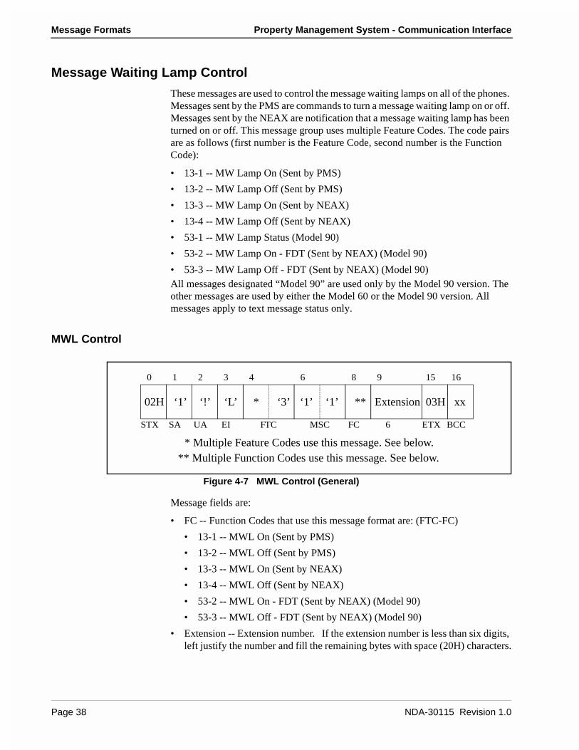
Message Formats Property Management System - Communication Interface
Message Waiting Lamp Control
These messages are used to control the message waiting lamps on all of the phones. Messages sent by the PMS are commands to turn a message waiting lamp on or off. Messages sent by the NEAX are notification that a message waiting lamp has been turned on or off. This message group uses multiple Feature Codes. The code pairs are as follows (first number is the Feature Code, second number is the Function Code):
• 13-1 -- MW Lamp On (Sent by PMS)
• 13-2 -- MW Lamp Off (Sent by PMS)
• 13-3 -- MW Lamp On (Sent by NEAX)
• 13-4 -- MW Lamp Off (Sent by NEAX)
• 53-1 -- MW Lamp Status (Model 90)
• 53-2 -- MW Lamp On - FDT (Sent by NEAX) (Model 90)
• 53-3 -- MW Lamp Off - FDT (Sent by NEAX) (Model 90)All messages designated “Model 90” are used only by the Model 90 version. The other messages are used by either the Model 60 or the Model 90 version. All messages apply to text message status only.
MWL Control
Figure 4-7 MWL Control (General)
Message fields are:
• FC -- Function Codes that use this message format are: (FTC-FC)
• 13-1 -- MWL On (Sent by PMS)
• 13-2 -- MWL Off (Sent by PMS)
• 13-3 -- MWL On (Sent by NEAX)
• 13-4 -- MWL Off (Sent by NEAX)
• 53-2 -- MWL On - FDT (Sent by NEAX) (Model 90)
• 53-3 -- MWL Off - FDT (Sent by NEAX) (Model 90)
• Extension -- Extension number. If the extension number is less than six digits, left justify the number and fill the remaining bytes with space (20H) characters.
* ‘3’ ‘1’ ‘1’ ** Extension
** Multiple Function Codes use this message. See below.* Multiple Feature Codes use this message. See below.
0 1 2 3 4 6 8 9 15 16
STX SA UA EI FTC MSC FC 6
02H ‘1’ ‘!’ ‘L’ 03H xx
ETX BCC
Page 38 NDA-30115 Revision 1.0
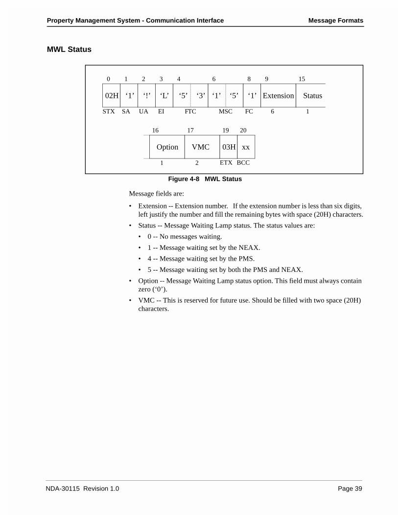
Property Management System - Communication Interface Message Formats
MWL Status
Figure 4-8 MWL Status
Message fields are:
• Extension -- Extension number. If the extension number is less than six digits, left justify the number and fill the remaining bytes with space (20H) characters.
• Status -- Message Waiting Lamp status. The status values are:
• 0 -- No messages waiting.
• 1 -- Message waiting set by the NEAX.
• 4 -- Message waiting set by the PMS.
• 5 -- Message waiting set by both the PMS and NEAX.
• Option -- Message Waiting Lamp status option. This field must always contain zero (‘0’).
• VMC -- This is reserved for future use. Should be filled with two space (20H) characters.
‘5’ ‘3’ ‘1’ ‘5’ ‘1’ Extension Status
Option VMC
0 1 2 3 4 6 8 9 15
STX SA UA EI FTC MSC FC 6 1
02H ‘1’ ‘!’ ‘L’
ETX BCC1 2
16 17 19 20
03H xx
NDA-30115 Revision 1.0 Page 39

Message Formats Property Management System - Communication Interface
Restriction Control
There are two messages. They are identical, except that message 15-1 is sent from the PMS to the NEAX, and message 15-2 is sent by the NEAX to the PMS. These messages simply communicate a new restriction code for an extension. These messages are used by both the Model 60 and the Model 90 version.
Figure 4-9 Restriction Control
Message fields are:
• FC-- There are two functions: (FTC-FC)
• 15-1 -- Originated from the PMS.
• 15-2 -- Originated from the NEAX.
• Extension -- Extension number. If the extension number is less than six digits, left justify the number and fill the remaining bytes with space (20H) characters.
• Code -- Restriction code for this extension. The possible codes are:
• 0 -- Do Not Disturb and Room Cut-Off are cancelled.
• 1 -- Room Cut-Off is set, Do Not Disturb is cancelled.
• 5 -- Do Not Disturb is set, Room Cut-Off is cancelled.
• 6 -- Do Not Disturb and Room Cut-Off are set.
• Blank -- Field contains two space (20H) characters.
‘1’ ‘5’ ‘1’ ‘4’ ** Extension Code
** Multiple Function Codes use this message. See below.
0 1 2 3 4 6 8 9 15
STX SA UA EI FTC MSC FC 6 1
02H ‘1’ ‘!’ ‘L’
03H xx
ETX BCC2
16 18 19
Blank
Page 40 NDA-30115 Revision 1.0

Property Management System - Communication Interface Message Formats
Check In/Check Out (Model 60)
These messages do not represent unique features as such, but are a convenient tool for activating a sequence of functions commonly performed when a guest checks in or out of a room. These messages are exclusively used by the Model 60 with the sole exception of Check Out Outgoing Call Report (16-C) which is also used by the Model 90 version.
The Feature Codes are as follows:
• 16-1 -- Check In 1
• 16-2 -- Check Out
• 16-5 -- Check Out Message Waiting Lamp Off Report
• 16-6 -- Check Out Message Waiting Lamp On Report
• 16-A -- Check In 2
• 16-B -- Check In 3
• 16-C -- Check Out Outgoing Call Report
• 16-D -- Check Out Message Waiting Report
Check In 1
Figure 4-10 Check In 1
The only message field is the extension number who is being checked in. If the extension number is less than six digits, left justify the number and fill the remaining bytes with space (20H) characters. The Room Status is set to “Stay” and Room Cut-Off is cancelled.
‘1’ ‘6’ ‘1’ ‘1’ ‘1’ Extension
0 1 2 3 4 6 8 9 15 16
STX SA UA EI FTC MSC FC 6
02H ‘1’ ‘!’ ‘L’ 03H xx
ETX BCC
NDA-30115 Revision 1.0 Page 41
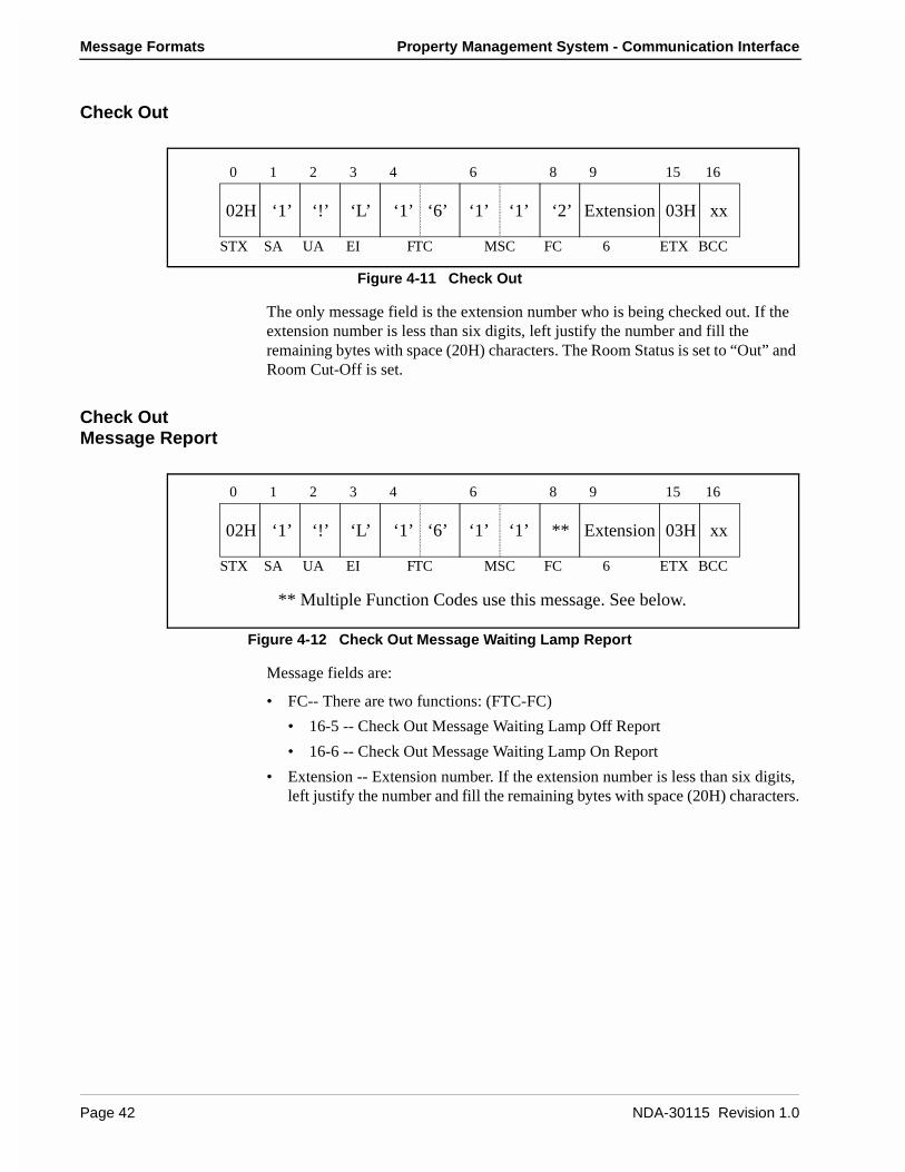
Message Formats Property Management System - Communication Interface
Check Out
Figure 4-11 Check Out
The only message field is the extension number who is being checked out. If the extension number is less than six digits, left justify the number and fill the remaining bytes with space (20H) characters. The Room Status is set to “Out” and Room Cut-Off is set.
Check Out Message Report
Figure 4-12 Check Out Message Waiting Lamp Report
Message fields are:
• FC-- There are two functions: (FTC-FC)
• 16-5 -- Check Out Message Waiting Lamp Off Report
• 16-6 -- Check Out Message Waiting Lamp On Report
• Extension -- Extension number. If the extension number is less than six digits, left justify the number and fill the remaining bytes with space (20H) characters.
‘2’‘1’ ‘6’ ‘1’ ‘1’ Extension
0 1 2 3 4 6 8 9 15 16
STX SA UA EI FTC MSC FC 6
02H ‘1’ ‘!’ ‘L’ 03H xx
ETX BCC
**
** Multiple Function Codes use this message. See below.
‘1’ ‘6’ ‘1’ ‘1’ Extension
0 1 2 3 4 6 8 9 15 16
STX SA UA EI FTC MSC FC 6
02H ‘1’ ‘!’ ‘L’ 03H xx
ETX BCC
Page 42 NDA-30115 Revision 1.0
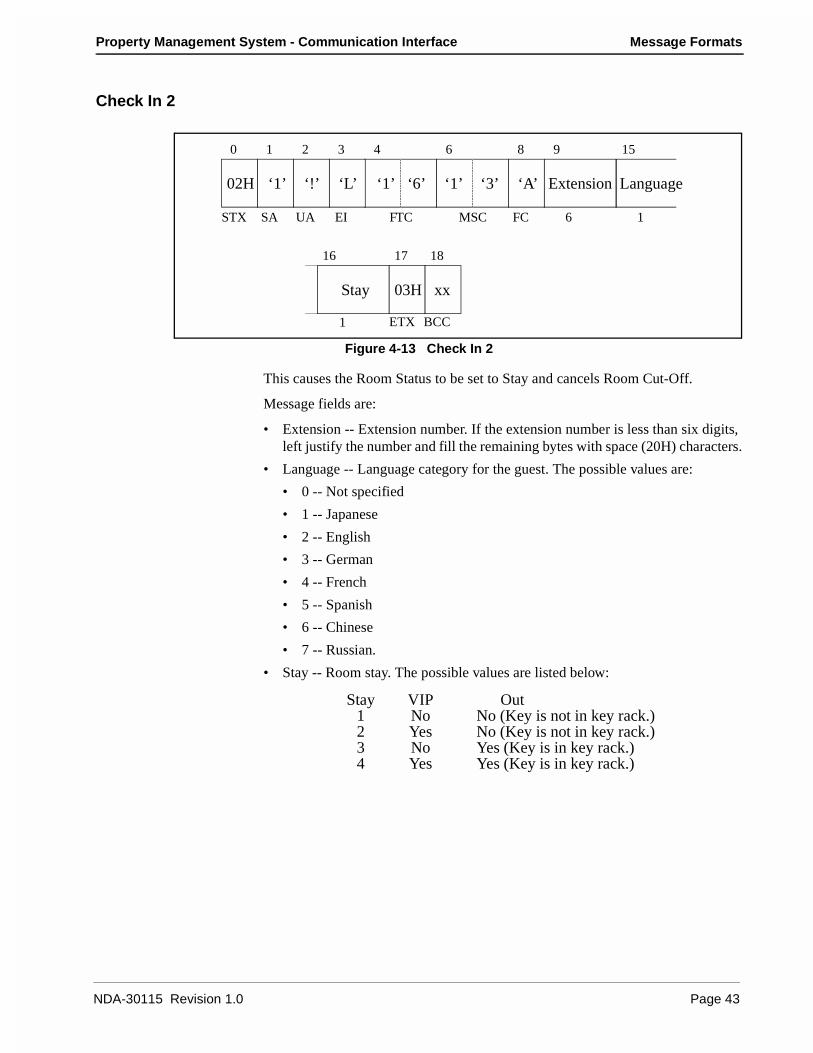
Property Management System - Communication Interface Message Formats
Check In 2
Figure 4-13 Check In 2
This causes the Room Status to be set to Stay and cancels Room Cut-Off.
Message fields are:
• Extension -- Extension number. If the extension number is less than six digits, left justify the number and fill the remaining bytes with space (20H) characters.
• Language -- Language category for the guest. The possible values are:
• 0 -- Not specified
• 1 -- Japanese
• 2 -- English
• 3 -- German
• 4 -- French
• 5 -- Spanish
• 6 -- Chinese
• 7 -- Russian.
• Stay -- Room stay. The possible values are listed below:
‘1’ ‘6’ ‘1’ ‘3’ ‘A’ Extension Language
0 1 2 3 4 6 8 9 15
STX SA UA EI FTC MSC FC 6 1
02H ‘1’ ‘!’ ‘L’
03H xx
ETX BCC1
16 17 18
Stay
Stay1234
VIPNoYesNoYes
OutNo (Key is not in key rack.)No (Key is not in key rack.)Yes (Key is in key rack.)Yes (Key is in key rack.)
NDA-30115 Revision 1.0 Page 43
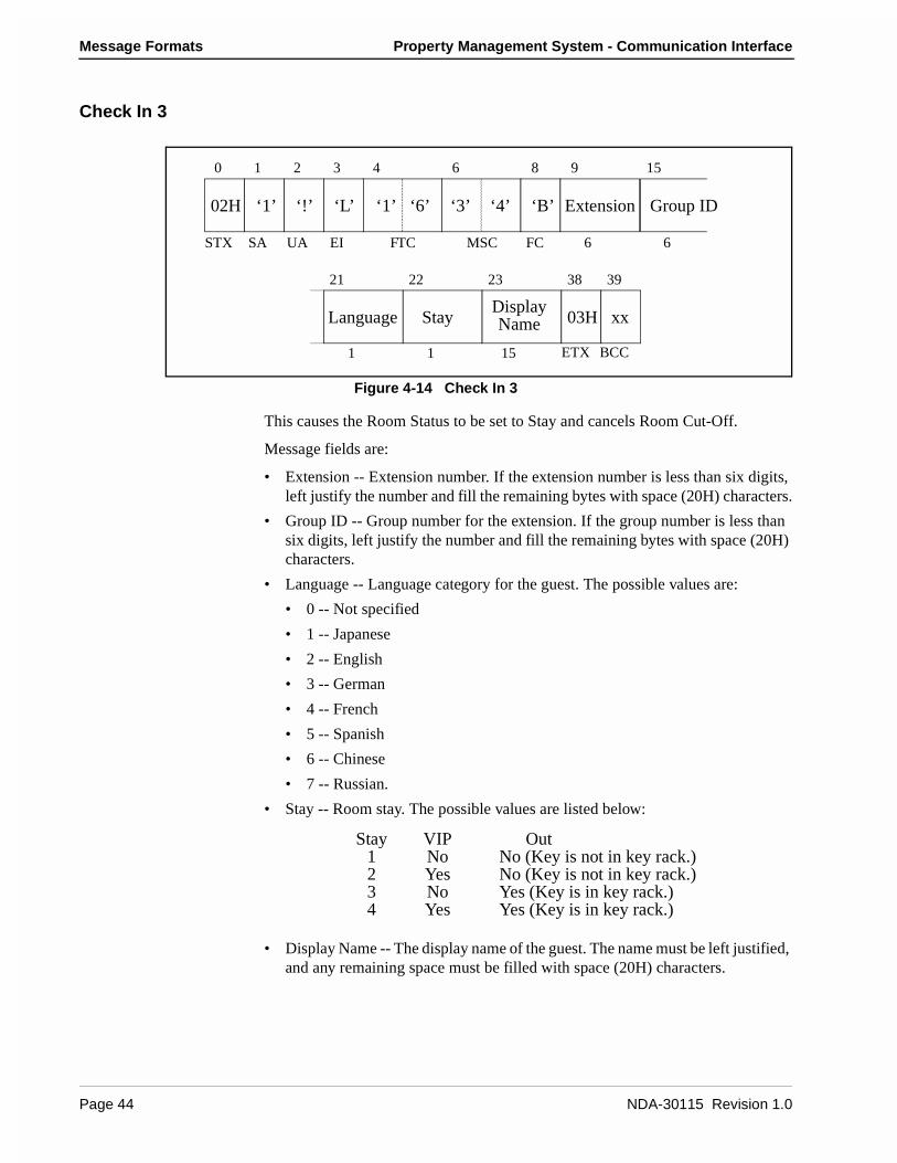
Message Formats Property Management System - Communication Interface
Check In 3
Figure 4-14 Check In 3
This causes the Room Status to be set to Stay and cancels Room Cut-Off.
Message fields are:
• Extension -- Extension number. If the extension number is less than six digits, left justify the number and fill the remaining bytes with space (20H) characters.
• Group ID -- Group number for the extension. If the group number is less than six digits, left justify the number and fill the remaining bytes with space (20H) characters.
• Language -- Language category for the guest. The possible values are:
• 0 -- Not specified
• 1 -- Japanese
• 2 -- English
• 3 -- German
• 4 -- French
• 5 -- Spanish
• 6 -- Chinese
• 7 -- Russian.
• Stay -- Room stay. The possible values are listed below:
• Display Name -- The display name of the guest. The name must be left justified, and any remaining space must be filled with space (20H) characters.
‘3’ ‘4’ ‘B’ Extension
Language Stay
Group ID
Display
‘1’ ‘6’
0 1 2 3 4 6 8 9 15
STX SA UA EI FTC MSC FC 6 6
02H ‘1’ ‘!’ ‘L’
ETX BCC1 1 15
21 22 23 38 39
Name 03H xx
Stay1234
VIPNoYesNoYes
OutNo (Key is not in key rack.)No (Key is not in key rack.)Yes (Key is in key rack.)Yes (Key is in key rack.)
Page 44 NDA-30115 Revision 1.0

Property Management System - Communication Interface Message Formats
Check Out Outgoing Call Report
Figure 4-15 Check Out Outgoing Call Report
The only message field is the extension number who is being checked out. Ifthe extension number is less than six digits, left justify the number and fillthe remaining bytes with space (20H) characters.
Check Out Message Waiting Report
Figure 4-16 Check Out
Message fields are:
• Extension -- Extension number. If the extension number is less than six digits, left justify the number and fill the remaining bytes with space (20H) characters.
• Status -- Message Waiting Lamp status. The status values are:
• 0 -- No messages waiting.
• 1 -- Message waiting set by the NEAX.
• 4 -- Message waiting set by the PMS.
• 5 -- Message waiting set by both the PMS and NEAX.
• Blank -- Field contains one space (20H) character.
‘C’‘1’ ‘6’ ‘1’ ‘1’ Extension
0 1 2 3 4 6 8 9 15 16
STX SA UA EI FTC MSC FC 6
02H ‘1’ ‘!’ ‘L’ 03H xx
ETX BCC
‘1’ ‘6’ ‘1’ ‘3’
0 1 2 3 4 6 8 9 15
STX SA UA EI FTC MSC FC 6 1
02H ‘1’ ‘!’ ‘L’
03H xx
ETX BCC1
16 17 18
Blank
‘D’ Extension Status
NDA-30115 Revision 1.0 Page 45
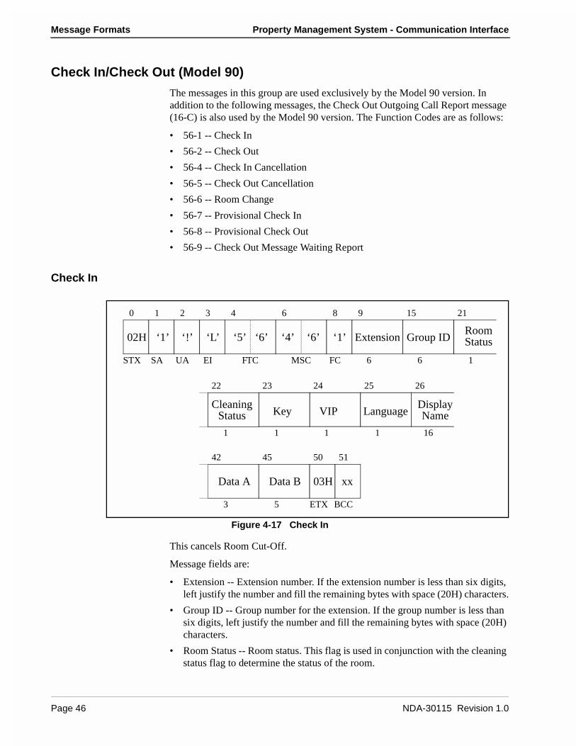
Message Formats Property Management System - Communication Interface
Check In/Check Out (Model 90)
The messages in this group are used exclusively by the Model 90 version. In addition to the following messages, the Check Out Outgoing Call Report message (16-C) is also used by the Model 90 version. The Function Codes are as follows:
• 56-1 -- Check In
• 56-2 -- Check Out
• 56-4 -- Check In Cancellation
• 56-5 -- Check Out Cancellation
• 56-6 -- Room Change
• 56-7 -- Provisional Check In
• 56-8 -- Provisional Check Out
• 56-9 -- Check Out Message Waiting Report
Check In
Figure 4-17 Check In
This cancels Room Cut-Off.
Message fields are:
• Extension -- Extension number. If the extension number is less than six digits, left justify the number and fill the remaining bytes with space (20H) characters.
• Group ID -- Group number for the extension. If the group number is less than six digits, left justify the number and fill the remaining bytes with space (20H) characters.
• Room Status -- Room status. This flag is used in conjunction with the cleaning status flag to determine the status of the room.
‘5’ ‘6’ ‘4’ ‘6’ ‘1’ Extension Group ID
KeyDisplay
VIP
Data A Data B
RoomStatus
0 1 2 3 4 6 8 9 15 21
STX SA UA EI FTC MSC FC 6 6 1
02H ‘1’ ‘!’ ‘L’
ETX BCC
1 1 1 1 16
22 23 24 25 26
3 5
42 45 50 51
03H xx
CleaningStatus NameLanguage
Page 46 NDA-30115 Revision 1.0

Property Management System - Communication Interface Message Formats
• Cleaning Status-- Cleaning status. The possible combinations with room status are listed below:
• Key -- Room key status:
• 0 -- Key is in the key rack.
• 1 -- Key is not in the key rack.
• VIP -- VIP category:
• 0 -- Guest is not a VIP.
• 1 -- Guest is a VIP.
• Language -- Language category for the guest. The possible values are:
• 0 -- Not specified
• 1 -- Japanese
• 2 -- English
• 3 -- German
• 4 -- French
• 5 -- Spanish
• 6 -- Chinese
• 7 -- Russian.
• Display Name -- The display name of the guest. The name must be left justified, and any remaining space must be filled with space (20H) characters.
• Data A & B-- Condition Data A and B. The contents of the option data are to be assigned on an individual hotel basis.
22
01
Stay, Departure DayStay, Departure Day, Cleaning in progress
Room11
Clean01
Status of the RoomStay (Occupied)Stay, Cleaning in progress
11
23
Stay, Cleaning endedStay, Inspected
NDA-30115 Revision 1.0 Page 47
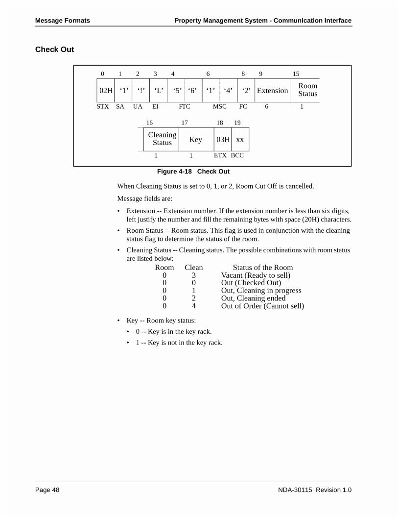
Message Formats Property Management System - Communication Interface
Check Out
Figure 4-18 Check Out
When Cleaning Status is set to 0, 1, or 2, Room Cut Off is cancelled.
Message fields are:
• Extension -- Extension number. If the extension number is less than six digits, left justify the number and fill the remaining bytes with space (20H) characters.
• Room Status -- Room status. This flag is used in conjunction with the cleaning status flag to determine the status of the room.
• Cleaning Status -- Cleaning status. The possible combinations with room status are listed below:
• Key -- Room key status:
• 0 -- Key is in the key rack.
• 1 -- Key is not in the key rack.
0 1 2 3 4 6 8 9 15
STX SA UA EI FTC MSC FC 6 1
02H ‘1’ ‘!’ ‘L’
03H xx
ETX BCC1 1
16 17 18 19
‘5’ ‘6’ ‘1’ ‘4’ ‘2’ ExtensionRoomStatus
KeyCleaning
Status
0000
0124
Out (Checked Out)Out, Cleaning in progressOut, Cleaning endedOut of Order (Cannot sell)
Room0
Clean3
Status of the RoomVacant (Ready to sell)
Page 48 NDA-30115 Revision 1.0
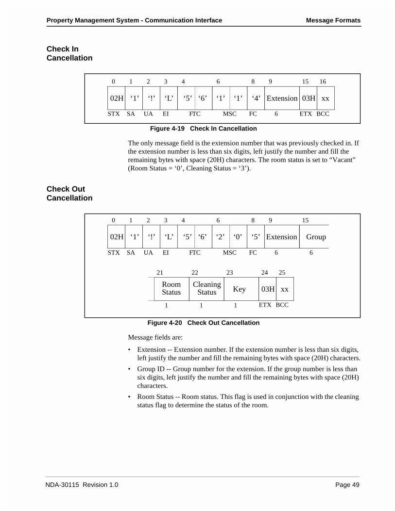
Property Management System - Communication Interface Message Formats
Check In Cancellation
Figure 4-19 Check In Cancellation
The only message field is the extension number that was previously checked in. If the extension number is less than six digits, left justify the number and fill the remaining bytes with space (20H) characters. The room status is set to “Vacant” (Room Status = ‘0’, Cleaning Status = ‘3’).
Check Out Cancellation
Figure 4-20 Check Out Cancellation
Message fields are:
• Extension -- Extension number. If the extension number is less than six digits, left justify the number and fill the remaining bytes with space (20H) characters.
• Group ID -- Group number for the extension. If the group number is less than six digits, left justify the number and fill the remaining bytes with space (20H) characters.
• Room Status -- Room status. This flag is used in conjunction with the cleaning status flag to determine the status of the room.
‘5’ ‘6’ ‘4’‘1’ ‘1’ Extension
0 1 2 3 4 6 8 9 15 16
STX SA UA EI FTC MSC FC 6
02H ‘1’ ‘!’ ‘L’ 03H xx
ETX BCC
KeyRoomStatus
CleaningStatus
0 1 2 3 4 6 8 9 15
STX SA UA EI FTC MSC FC 6 6
02H ‘1’ ‘!’ ‘L’
03H xx
ETX BCC1 1 1
21 22 23 24 25
‘5’ ‘6’ ‘2’ ‘0’ ‘5’ Extension Group
NDA-30115 Revision 1.0 Page 49

Message Formats Property Management System - Communication Interface
• Cleaning Status -- Cleaning status. The possible combinations with room status are listed below:
• Key -- Room key status:
• 0 -- Key is in the key rack.
• 1 -- Key is not in the key rack.
Room Change
Figure 4-21 Room Change
Message fields are:
• Old Extension -- Old extension number. If the extension number is less than six digits, left justify the number and fill the remaining bytes with space (20H) characters.
• Room Status 1 -- Room status of the old room. This flag is used in conjunction with the cleaning status flag to determine the status of the room.
• Cleaning Status 1 -- Cleaning status of the old room. The possible combinations with room status are listed below:
22
01
Stay, Departure DayStay, Departure Day, Cleaning in progress
Room11
Clean01
Status of the RoomStay (Occupied)Stay, Cleaning in progress
11
23
Stay, Cleaning endedStay, Inspected
‘5’ ‘6’
0 1 2 3 4 6 8 9 15 16
STX SA UA EI FTC MSC FC 6 1 1
02H ‘1’ ‘!’ ‘L’
03H xx
ETX BCC1 6 1 1 1
17 18 24 25 26 27 28
‘2’ ‘3’ ‘6’Old
ExtensionRoom
Status 1CleaningStatus 1
KeyNew
Extension KeyRoom
Status 2CleaningStatus 2
0000
0124
Out (Checked Out)Out, Cleaning in progressOut, Cleaning endedOut of Order (Cannot sell)
Room0
Clean3
Status of the RoomVacant (Ready to sell)
Page 50 NDA-30115 Revision 1.0

Property Management System - Communication Interface Message Formats
• Key -- Old room key status:
• 0 -- Key is in the key rack.
• 1 -- Key is not in the key rack.
• New Extension -- New extension number. If the extension number is less than six digits, left justify the number and fill the remaining bytes with space (20H) characters.
• Room Status 2 -- Room status of the new room. This flag is used in conjunction with the cleaning status flag to determine the status of the room.
• Cleaning Status 2 -- Cleaning status of the new room. The possible combinations with room status are listed below:
• Key -- New room key status:
• 0 -- Key is in the key rack.
• 1 -- Key is not in the key rack.
Provisional Check In
Figure 4-22 Provisional Check In
The only message field is the extension number that has been provisionally checked in. If the extension number is less than six digits, left justify the number and fill the remaining bytes with space (20H) characters. The room status is set to “Stay” (Room Status = ‘1’, Cleaning Status = ‘0’) and Room Cut-Off is cancelled.
Room11
Clean01
Status of the RoomStay (Occupied)Stay, Cleaning in progress
11
23
Stay, Cleaning endedStay, Inspected
‘5’ ‘6’ ‘1’ ‘1’ Extension
0 1 2 3 4 6 8 9 15 16
STX SA UA EI FTC MSC FC 6
02H ‘1’ ‘!’ ‘L’ 03H xx
ETX BCC
‘7’
NDA-30115 Revision 1.0 Page 51

Message Formats Property Management System - Communication Interface
Provisional Check Out
Figure 4-23 Provisional Check out
The only message field is the extension number that has been provisionally checked out. If the extension number is less than six digits, left justify the number and fill the remaining bytes with space (20H) characters. When maid status is not performed, room status is set to “Vacant” (Room Status = ‘0’, Cleaning Status = ‘3’); if maid status is performed, room status is set to “Out” (Room Status = ‘0’, Cleaning Status = ‘0’).
Check Out Message Waiting Report
Figure 4-24 Check Out Message Waiting Report
Message fields are:
• Extension -- Extension number. If the extension number is less than six digits, left justify the number and fill the remaining bytes with space (20H) characters.
• Status -- Message Waiting Lamp status. The status values are:• 0 -- No text messages waiting.• 1 -- Message waiting set by the NEAX.• 4 -- Message waiting set by the PMS.• 5 -- Message waiting set by the PMS and the NEAX.
• Option -- Message Waiting status option. This field must always contain zero (‘0’).
• VMC -- This is reserved for future use. Should be filled with two space (20H) characters.
‘5’ ‘6’ ‘1’ ‘1’ Extension
0 1 2 3 4 6 8 9 15 16
STX SA UA EI FTC MSC FC 6
02H ‘1’ ‘!’ ‘L’ 03H xx
ETX BCC
‘8’
‘1’ ‘5’ ‘9’ Status
Option VMC
0 1 2 3 4 6 8 9 15
STX SA UA EI FTC MSC FC 6 1
02H ‘1’ ‘!’ ‘L’
03H xx
ETX BCC1 2
16 17 19 20
‘5’ ‘6’ Extension
Page 52 NDA-30115 Revision 1.0

Property Management System - Communication Interface Message Formats
Wake Up/Group Announcement
The Function Codes are as follows:
• 19-1 -- Wake Up Setting (Sent by NEAX)
• 19-2 -- Wake Up Cancellation (Sent by NEAX)
• 19-3 -- Wake Up Execution Result
• 19-4 -- Wake Up Setting (Sent by PMS)
• 19-5 -- Wake Up Cancellation (Sent by PMS)
• 19-6 -- Group Announcement Setting (Sent by NEAX)
• 19-7 -- Group Announcement Cancellation (Sent by NEAX)
• 19-8 -- Group Announcement Execution Result
• 19-9 -- Group Announcement Setting (Sent by PMS)
• 19-A -- Group Announcement Cancellation (Sent by PMS)These messages are used by both the Model 60 and the Model 90 versions.
Wake Up Setting (NEAX)
Figure 4-25 Wake Up Setting (NEAX)
Message fields are:
• Extension -- Extension number. If the extension number is less than six digits, left justify the number and fill the remaining bytes with space (20H) characters.
• Time -- Time for which a wake up call is set. Format used is HHMM using military time.
• Source -- Code for the source of the wake up setting. Possible values are:
• 1 -- Guest Extension.
• 2 -- Attendant.
• 3 -- Administration Extension.
• 4 -- Property Management System.
0 1 2 3 4 6 8 9 15
STX SA UA EI FTC MSC FC 6 4
02H ‘1’ ‘!’ ‘L’
03H xx
ETX BCC1
19 20 21
‘1’ ‘9’ ‘1’ ‘6’ ‘1’ Extension Time
Source
NDA-30115 Revision 1.0 Page 53

Message Formats Property Management System - Communication Interface
Wake Up Cancellation (NEAX)
Figure 4-26 Wake Up Cancellation (NEAX)
Message fields are:
• Extension -- Extension number. If the extension number is less than six digits, left justify the number and fill the remaining bytes with space (20H) characters.
• Blank -- Field contains four space (20H) characters.
• Source -- Code for the source of the wake up setting. Possible values are:
• 1 -- Guest Extension.
• 2 -- Attendant.
• 3 -- Administration Extension.
• 4 -- Property Management System.
0 1 2 3 4 6 8 9 15
STX SA UA EI FTC MSC FC 6 4
02H ‘1’ ‘!’ ‘L’
03H xx
ETX BCC1
19 20 21
‘1’ ‘9’ ‘1’ ‘6’ ‘2’ Extension Blank
Source
Page 54 NDA-30115 Revision 1.0

Property Management System - Communication Interface Message Formats
Wake Up Execution Result
Figure 4-27 Wake Up Execution Result
Message fields are:
• Extension -- Extension number. If the extension number is less than six digits, left justify the number and fill the remaining bytes with space (20H) characters.
• Time -- Time for which a wake up was set. Format used is HHMM using military time.
• Result -- Code for the result of the wake up call. Possible values are:
• 1 -- Answer.
• 2 -- Busy.
• 3 -- No answer.
• 4 -- Block.
• 5 -- Call Termination to Attendant Console.
0 1 2 3 4 6 8 9 15
STX SA UA EI FTC MSC FC 6 4
02H ‘1’ ‘!’ ‘L’
03H xx
ETX BCC1
19 20 21
‘1’ ‘9’ ‘1’ ‘6’ ‘3’ Extension Time
Result
NDA-30115 Revision 1.0 Page 55
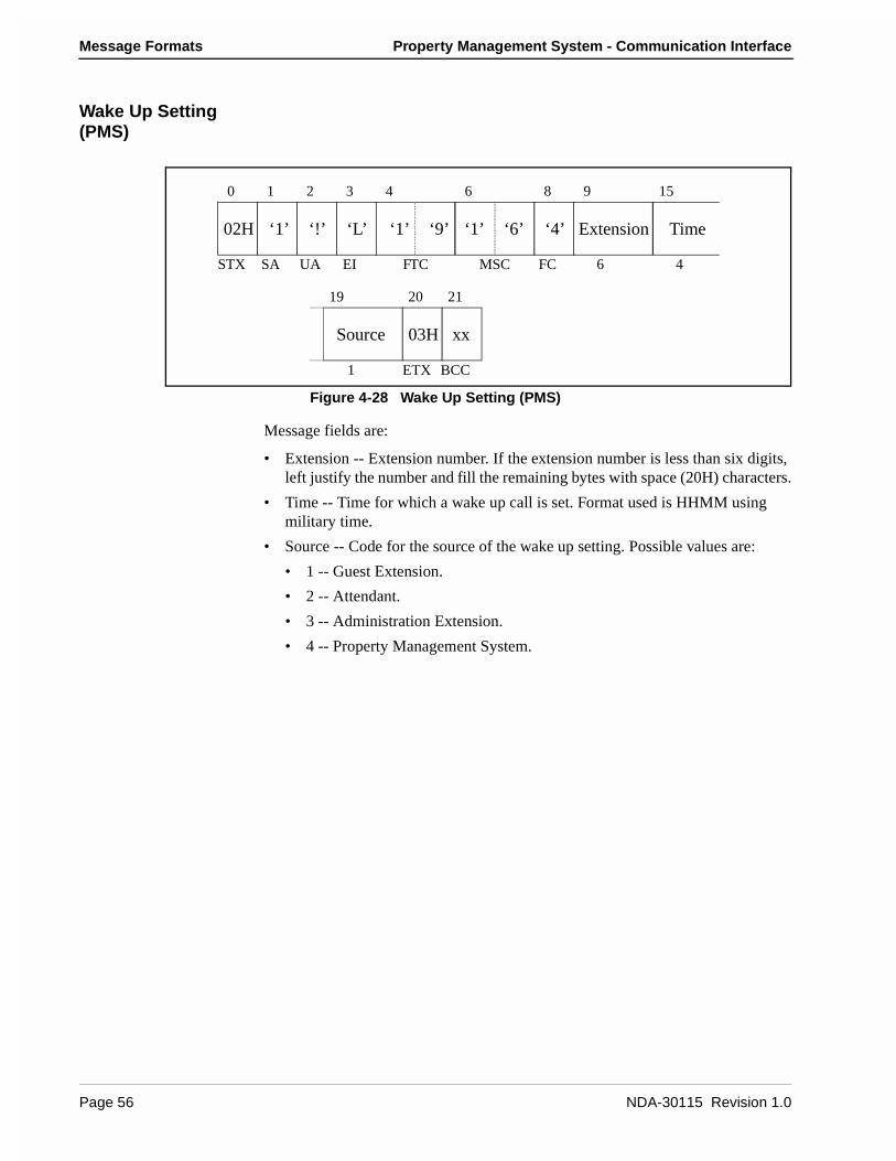
Message Formats Property Management System - Communication Interface
Wake Up Setting (PMS)
Figure 4-28 Wake Up Setting (PMS)
Message fields are:
• Extension -- Extension number. If the extension number is less than six digits, left justify the number and fill the remaining bytes with space (20H) characters.
• Time -- Time for which a wake up call is set. Format used is HHMM using military time.
• Source -- Code for the source of the wake up setting. Possible values are:
• 1 -- Guest Extension.
• 2 -- Attendant.
• 3 -- Administration Extension.
• 4 -- Property Management System.
0 1 2 3 4 6 8 9 15
STX SA UA EI FTC MSC FC 6 4
02H ‘1’ ‘!’ ‘L’
03H xx
ETX BCC1
19 20 21
‘1’ ‘9’ ‘1’ ‘6’ ‘4’ Extension Time
Source
Page 56 NDA-30115 Revision 1.0

Property Management System - Communication Interface Message Formats
Wake Up Cancellation (PMS)
Figure 4-29 Wake Up Cancellation (PMS)
Message fields are:
• Extension -- Extension number. If the extension number is less than six digits, left justify the number and fill the remaining bytes with space (20H) characters.
• Blank -- Field contains four space (20H) characters.
• Source -- Code for the source of the wake up setting. Possible values are:
• 1 -- Guest Extension.
• 2 -- Attendant.
• 3 -- Administration Extension.
• 4 -- Property Management System.
0 1 2 3 4 6 8 9 15
STX SA UA EI FTC MSC FC 6 4
02H ‘1’ ‘!’ ‘L’
03H xx
ETX BCC1
19 20 21
‘1’ ‘9’ ‘1’ ‘6’ ‘5’ Extension Blank
Source
NDA-30115 Revision 1.0 Page 57
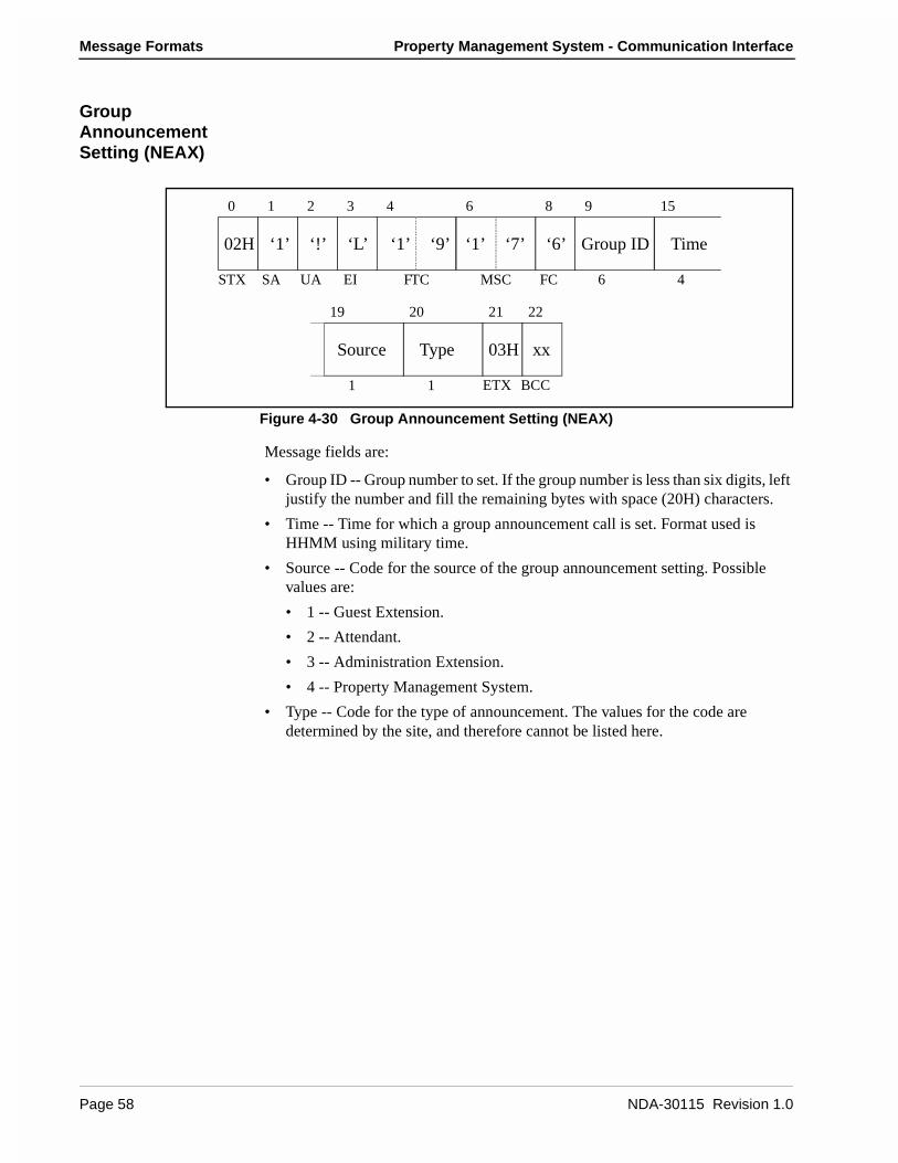
Message Formats Property Management System - Communication Interface
Group Announcement Setting (NEAX)
Figure 4-30 Group Announcement Setting (NEAX)
Message fields are:
• Group ID -- Group number to set. If the group number is less than six digits, left justify the number and fill the remaining bytes with space (20H) characters.
• Time -- Time for which a group announcement call is set. Format used is HHMM using military time.
• Source -- Code for the source of the group announcement setting. Possible values are:
• 1 -- Guest Extension.
• 2 -- Attendant.
• 3 -- Administration Extension.
• 4 -- Property Management System.
• Type -- Code for the type of announcement. The values for the code are determined by the site, and therefore cannot be listed here.
Type
0 1 2 3 4 6 8 9 15
STX SA UA EI FTC MSC FC 6 4
02H ‘1’ ‘!’ ‘L’
03H xx
ETX BCC1 1
19 20 21 22
‘1’ ‘9’ ‘1’ ‘7’ ‘6’ Group ID Time
Source
Page 58 NDA-30115 Revision 1.0

Property Management System - Communication Interface Message Formats
Group Announcement Cancellation (NEAX)
Figure 4-31 Group Announcement Cancellation (NEAX)
Message fields are:
• Group ID -- Group number to cancel. If the group number is less than six digits, left justify the number and fill the remaining bytes with space (20H) characters.
• Blank -- Field contains four space (20H) characters.
• Source -- Code for the source of the group announcement setting. Possible values are:
• 1 -- Guest Extension.
• 2 -- Attendant.
• 3 -- Administration Extension.
• 4 -- Property Management System.
0 1 2 3 4 6 8 9 15
STX SA UA EI FTC MSC FC 6 4
02H ‘1’ ‘!’ ‘L’
03H xx
ETX BCC1
19 20 21
‘1’ ‘9’ ‘1’ ‘6’ ‘7’ Group ID Blank
Source
NDA-30115 Revision 1.0 Page 59
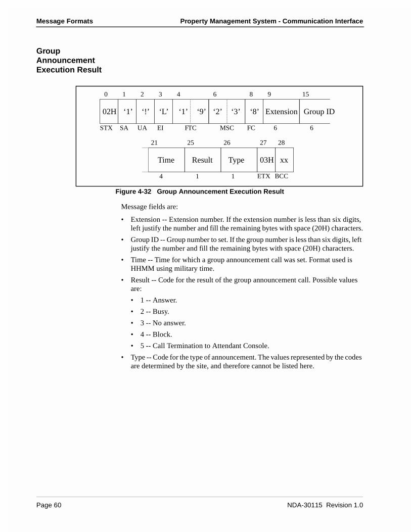
Message Formats Property Management System - Communication Interface
Group Announcement Execution Result
Figure 4-32 Group Announcement Execution Result
Message fields are:
• Extension -- Extension number. If the extension number is less than six digits, left justify the number and fill the remaining bytes with space (20H) characters.
• Group ID -- Group number to set. If the group number is less than six digits, left justify the number and fill the remaining bytes with space (20H) characters.
• Time -- Time for which a group announcement call was set. Format used is HHMM using military time.
• Result -- Code for the result of the group announcement call. Possible values are:
• 1 -- Answer.
• 2 -- Busy.
• 3 -- No answer.
• 4 -- Block.
• 5 -- Call Termination to Attendant Console.
• Type -- Code for the type of announcement. The values represented by the codes are determined by the site, and therefore cannot be listed here.
Result Type
0 1 2 3 4 6 8 9 15
STX SA UA EI FTC MSC FC 6 6
02H ‘1’ ‘!’ ‘L’
03H xx
ETX BCC4 1 1
21 25 26 27 28
‘1’ ‘9’ ‘2’ ‘3’ ‘8’ Extension Group ID
Time
Page 60 NDA-30115 Revision 1.0
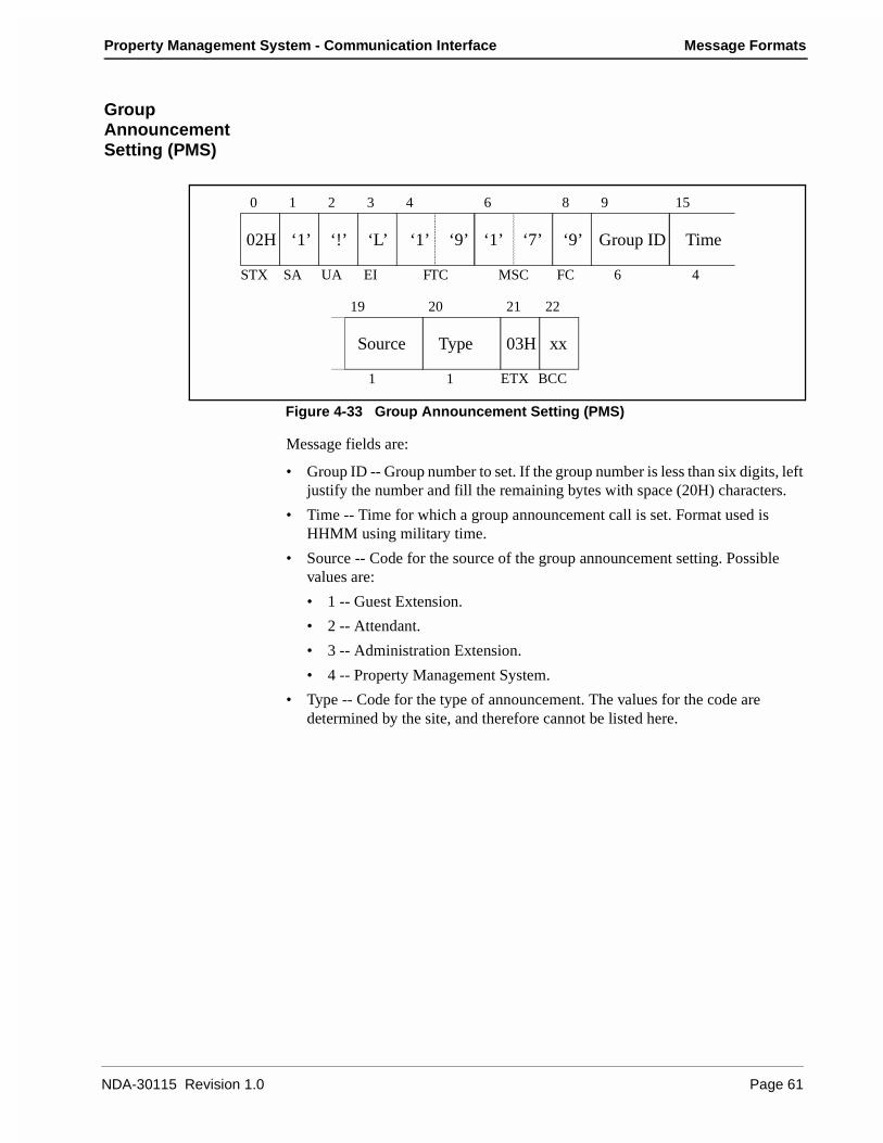
Property Management System - Communication Interface Message Formats
Group Announcement Setting (PMS)
Figure 4-33 Group Announcement Setting (PMS)
Message fields are:
• Group ID -- Group number to set. If the group number is less than six digits, left justify the number and fill the remaining bytes with space (20H) characters.
• Time -- Time for which a group announcement call is set. Format used is HHMM using military time.
• Source -- Code for the source of the group announcement setting. Possible values are:
• 1 -- Guest Extension.
• 2 -- Attendant.
• 3 -- Administration Extension.
• 4 -- Property Management System.
• Type -- Code for the type of announcement. The values for the code are determined by the site, and therefore cannot be listed here.
Type
0 1 2 3 4 6 8 9 15
STX SA UA EI FTC MSC FC 6 4
02H ‘1’ ‘!’ ‘L’
03H xx
ETX BCC1 1
19 20 21 22
‘1’ ‘9’ ‘1’ ‘7’ ‘9’ Group ID Time
Source
NDA-30115 Revision 1.0 Page 61
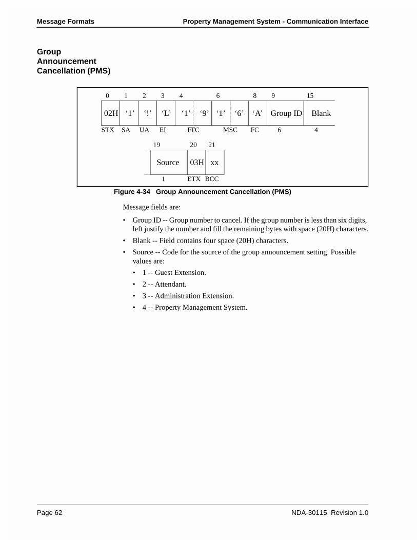
Message Formats Property Management System - Communication Interface
Group Announcement Cancellation (PMS)
Figure 4-34 Group Announcement Cancellation (PMS)
Message fields are:
• Group ID -- Group number to cancel. If the group number is less than six digits, left justify the number and fill the remaining bytes with space (20H) characters.
• Blank -- Field contains four space (20H) characters.
• Source -- Code for the source of the group announcement setting. Possible values are:
• 1 -- Guest Extension.
• 2 -- Attendant.
• 3 -- Administration Extension.
• 4 -- Property Management System.
0 1 2 3 4 6 8 9 15
STX SA UA EI FTC MSC FC 6 4
02H ‘1’ ‘!’ ‘L’
03H xx
ETX BCC1
19 20 21
‘1’ ‘9’ ‘1’ ‘6’ ‘A’ Group ID Blank
Source
Page 62 NDA-30115 Revision 1.0
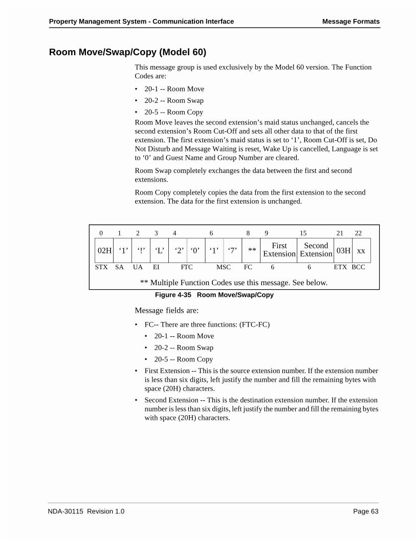
Property Management System - Communication Interface Message Formats
Room Move/Swap/Copy (Model 60)
This message group is used exclusively by the Model 60 version. The Function Codes are:
• 20-1 -- Room Move
• 20-2 -- Room Swap
• 20-5 -- Room CopyRoom Move leaves the second extension’s maid status unchanged, cancels the second extension’s Room Cut-Off and sets all other data to that of the first extension. The first extension’s maid status is set to ‘1’, Room Cut-Off is set, Do Not Disturb and Message Waiting is reset, Wake Up is cancelled, Language is set to ‘0’ and Guest Name and Group Number are cleared.
Room Swap completely exchanges the data between the first and second extensions.
Room Copy completely copies the data from the first extension to the second extension. The data for the first extension is unchanged.
Figure 4-35 Room Move/Swap/Copy
Message fields are:
• FC-- There are three functions: (FTC-FC)
• 20-1 -- Room Move
• 20-2 -- Room Swap
• 20-5 -- Room Copy
• First Extension -- This is the source extension number. If the extension number is less than six digits, left justify the number and fill the remaining bytes with space (20H) characters.
• Second Extension -- This is the destination extension number. If the extension number is less than six digits, left justify the number and fill the remaining bytes with space (20H) characters.
‘2’ ‘0’ ‘1’ ‘7’ **First Second
** Multiple Function Codes use this message. See below.
Extension Extension
0 1 2 3 4 6 8 9 15 21 22
STX SA UA EI FTC MSC FC 6 6
02H ‘1’ ‘!’ ‘L’ 03H xx
ETX BCC
NDA-30115 Revision 1.0 Page 63
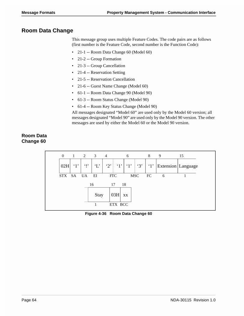
Message Formats Property Management System - Communication Interface
Room Data Change
This message group uses multiple Feature Codes. The code pairs are as follows (first number is the Feature Code, second number is the Function Code):
• 21-1 -- Room Data Change 60 (Model 60)
• 21-2 -- Group Formation
• 21-3 -- Group Cancellation
• 21-4 -- Reservation Setting
• 21-5 -- Reservation Cancellation
• 21-6 -- Guest Name Change (Model 60)
• 61-1 -- Room Data Change 90 (Model 90)
• 61-3 -- Room Status Change (Model 90)
• 61-4 -- Room Key Status Change (Model 90)All messages designated “Model 60” are used only by the Model 60 version; all messages designated “Model 90” are used only by the Model 90 version. The other messages are used by either the Model 60 or the Model 90 version.
Room Data Change 60
Figure 4-36 Room Data Change 60
0 1 2 3 4 6 8 9 15
STX SA UA EI FTC MSC FC 6 1
02H ‘1’ ‘!’ ‘L’
03H xx
ETX BCC1
16 17 18
Stay
‘2’ ‘1’ ‘1’ ‘3’ ‘1’ Extension Language
Page 64 NDA-30115 Revision 1.0

Property Management System - Communication Interface Message Formats
Message fields are:
• Extension -- Extension number. If the extension number is less than six digits, left justify the number and fill the remaining bytes with space (20H) characters.
• Language -- Language category for the guest. The possible values are:
• 0 -- Not specified
• 1 -- Japanese
• 2 -- English
• 3 -- German
• 4 -- French
• 5 -- Spanish
• 6 -- Chinese
• 7 -- Russian.
• Stay -- Room stay. The possible values are listed below:
Group Formation
Figure 4-37 Group Formation
Message fields are:
• Extension -- Extension number. If the extension number is less than six digits, left justify the number and fill the remaining bytes with space (20H) characters.
• Group ID -- Group number to join. If the group number is less than six digits, left justify the number and fill the remaining bytes with space (20H) characters.
Stay1234
VIPNoYesNoYes
OutNo (Key is not in key rack.)No (Key is not in key rack.)Yes (Key is in key rack.)Yes (Key is in key rack.)
‘2’ ‘1’ ‘1’ ‘7’ ‘2’ Extension Group ID
0 1 2 3 4 6 8 9 15 21 22
STX SA UA EI FTC MSC FC 6 6
02H ‘1’ ‘!’ ‘L’ 03H xx
ETX BCC
NDA-30115 Revision 1.0 Page 65
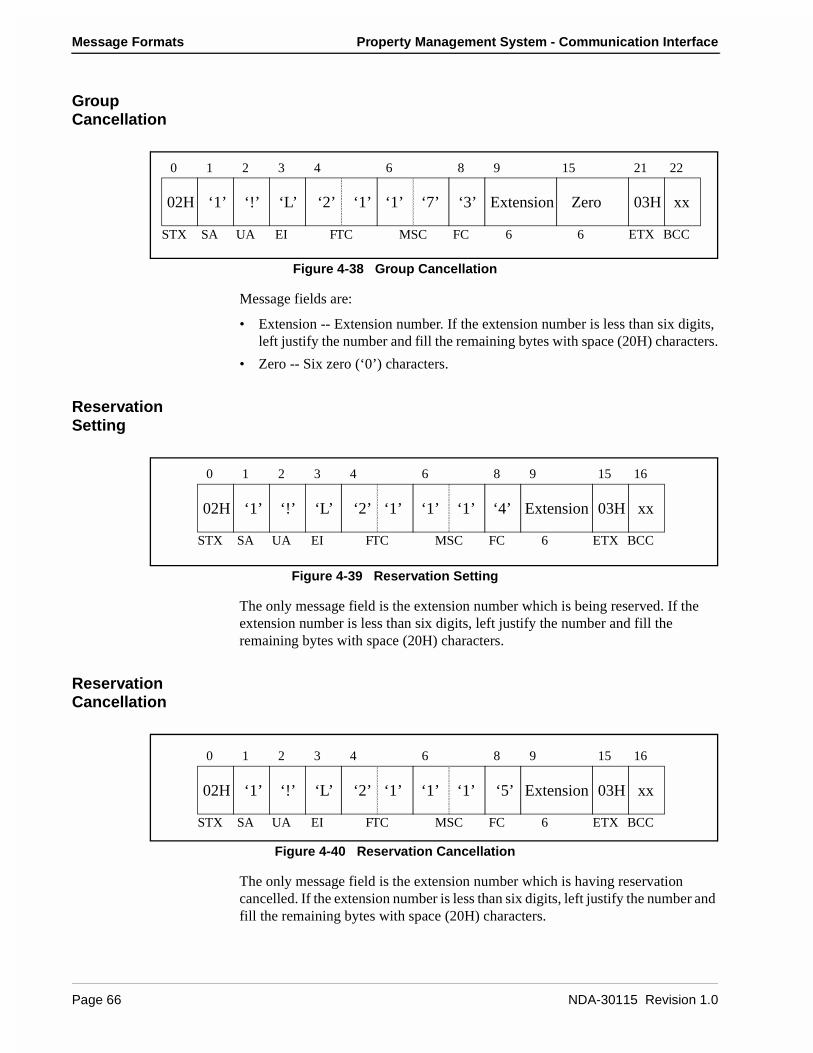
Message Formats Property Management System - Communication Interface
Group Cancellation
Figure 4-38 Group Cancellation
Message fields are:
• Extension -- Extension number. If the extension number is less than six digits, left justify the number and fill the remaining bytes with space (20H) characters.
• Zero -- Six zero (‘0’) characters.
Reservation Setting
Figure 4-39 Reservation Setting
The only message field is the extension number which is being reserved. If the extension number is less than six digits, left justify the number and fill the remaining bytes with space (20H) characters.
Reservation Cancellation
Figure 4-40 Reservation Cancellation
The only message field is the extension number which is having reservation cancelled. If the extension number is less than six digits, left justify the number and fill the remaining bytes with space (20H) characters.
‘2’ ‘1’ ‘1’ ‘7’ ‘3’ Extension Zero
0 1 2 3 4 6 8 9 15 21 22
STX SA UA EI FTC MSC FC 6 6
02H ‘1’ ‘!’ ‘L’ 03H xx
ETX BCC
‘2’ ‘1’ ‘1’ ‘1’ ‘4’ Extension
0 1 2 3 4 6 8 9 15 16
STX SA UA EI FTC MSC FC 6
02H ‘1’ ‘!’ ‘L’ 03H xx
ETX BCC
‘5’‘2’ ‘1’ ‘1’ ‘1’ Extension
0 1 2 3 4 6 8 9 15 16
STX SA UA EI FTC MSC FC 6
02H ‘1’ ‘!’ ‘L’ 03H xx
ETX BCC
Page 66 NDA-30115 Revision 1.0

Property Management System - Communication Interface Message Formats
Guest Name Change
Figure 4-41 Guest Name Change
Message fields are:
• Extension -- Extension number. If the extension number is less than six digits, left justify the number and fill the remaining bytes with space (20H) characters.
• Display Name -- The display name of the guest. The name must be left justified, and any remaining space must be filled with space (20H) characters.
Room Data Change 90
Figure 4-42 Room Data Change 90
This message is to be used only if the extension has been checked in.
Message fields are:
• Extension -- Extension number. If the extension number is less than six digits, left justify the number and fill the remaining bytes with space (20H) characters.
• Group ID -- Group number for the extension. If the group number is less than six digits, left justify the number and fill the remaining bytes with space (20H) characters.
‘2’ ‘1’ ‘2’ ‘6’ ‘6’ Extension Display
0 1 2 3 4 6 8 9 15 30 31
STX SA UA EI FTC MSC FC 6 15
02H ‘1’ ‘!’ ‘L’ 03H xx
ETX BCC
Name
‘6’ ‘1’ ‘4’ ‘6’ ‘1’ Extension Group ID
Key LanguageDisplay
VIP
Data A Data B
RoomStatus
0 1 2 3 4 6 8 9 15 21
STX SA UA EI FTC MSC FC 6 6 1
02H ‘1’ ‘!’ ‘L’
ETX BCC
1 1 1 1 16
22 23 24 25 26
3 5
42 45 50 51
NameCleaning
Status
03H xx
NDA-30115 Revision 1.0 Page 67
Message Formats Property Management System - Communication Interface
• Room Status -- Room status. This flag is used in conjunction with the cleaning status flag to determine the status of the room.
• Cleaning Status -- Cleaning status. The possible combinations with room status are listed below:
• Key -- Room key status:
• 0 -- Key is in the key rack.
• 1 -- Key is not in the key rack.
• VIP -- VIP category:
• 0 -- Guest is not a VIP.
• 1 -- Guest is a VIP.
• Language -- Language category for the guest. The possible values are:
• 0 -- Not specified
• 1 -- Japanese
• 2 -- English
• 3 -- German
• 4 -- French
• 5 -- Spanish
• 6 -- Chinese
• 7 -- Russian.
• Display Name -- The display name of the guest. The name must be left justified, and any remaining space must be filled with space (20H) characters.
• Data A & B-- Condition Data A and B. The contents of the option data are to be assigned on an individual hotel basis.
22
01
Stay, Departure DayStay, Departure Day, Cleaning in progress
Room11
Clean01
Status of the RoomStay (Occupied)Stay, Cleaning in progress
11
23
Stay, Cleaning endedStay, Inspected
Page 68 NDA-30115 Revision 1.0

Property Management System - Communication Interface Message Formats
Room Status Change
Figure 4-43 Room Status Change
If Room Status is set to ‘0’ and Cleaning Status is set to either ‘3’ or ‘4’, the room data is cleared.
If Room Status is set to ‘0’ and the previous Room Status had been ‘1’ or ‘2’, Room Cut-Off is set and the Group registration is cancelled as in the case of a Check Out.
Message fields are:
• Extension -- Extension number. If the extension number is less than six digits, left justify the number and fill the remaining bytes with space (20H) characters.
• Room Status -- Room status. This flag is used in conjunction with the cleaning status flag to determine the status of the room.
• Cleaning Status -- Cleaning status. The possible combinations with room status are listed below:
‘6’ ‘1’ ‘1’ ‘3’ ‘3’ ExtensionRoomStatus
CleaningStatus
0 1 2 3 4 6 8 9 15
STX SA UA EI FTC MSC FC 6 1
02H ‘1’ ‘!’ ‘L’
03H xx
ETX BCC1
16 17 18
220000
010124
Stay, Departure DayStay, Departure Day, Cleaning in progressOut (Checked Out)Out, Cleaning in progressOut, Cleaning endedOut of Order (Cannot sell)
Room011
Clean301
Status of the RoomVacant (Ready to sell)Stay (Occupied)Stay, Cleaning in progress
11
23
Stay, Cleaning endedStay, Inspected
NDA-30115 Revision 1.0 Page 69
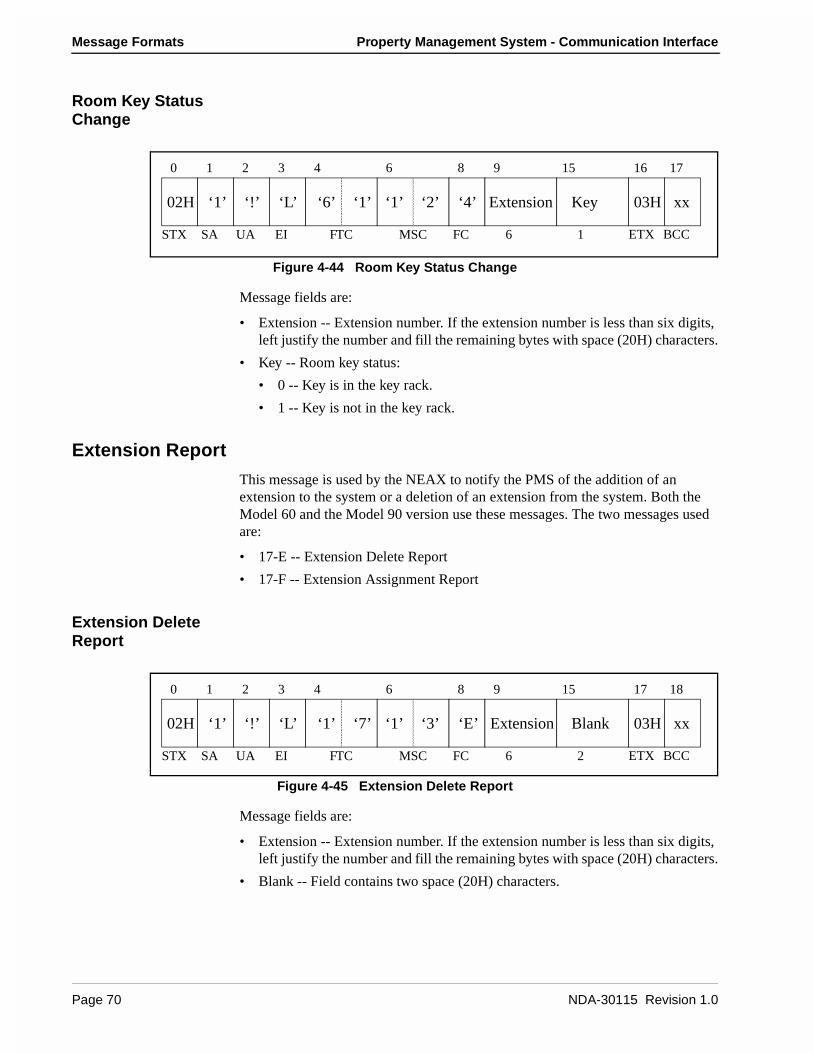
Message Formats Property Management System - Communication Interface
Room Key Status Change
Figure 4-44 Room Key Status Change
Message fields are:
• Extension -- Extension number. If the extension number is less than six digits, left justify the number and fill the remaining bytes with space (20H) characters.
• Key -- Room key status:
• 0 -- Key is in the key rack.
• 1 -- Key is not in the key rack.
Extension Report
This message is used by the NEAX to notify the PMS of the addition of an extension to the system or a deletion of an extension from the system. Both the Model 60 and the Model 90 version use these messages. The two messages used are:
• 17-E -- Extension Delete Report
• 17-F -- Extension Assignment Report
Extension Delete Report
Figure 4-45 Extension Delete Report
Message fields are:
• Extension -- Extension number. If the extension number is less than six digits, left justify the number and fill the remaining bytes with space (20H) characters.
• Blank -- Field contains two space (20H) characters.
‘6’ ‘1’ ‘1’ ‘2’ ‘4’ Extension Key
0 1 2 3 4 6 8 9 15 16 17
STX SA UA EI FTC MSC FC 6 1
02H ‘1’ ‘!’ ‘L’ 03H xx
ETX BCC
‘1’ ‘7’ ‘1’ ‘3’ ‘E’ Extension Blank
0 1 2 3 4 6 8 9 15 17 18
STX SA UA EI FTC MSC FC 6 2
02H ‘1’ ‘!’ ‘L’ 03H xx
ETX BCC
Page 70 NDA-30115 Revision 1.0
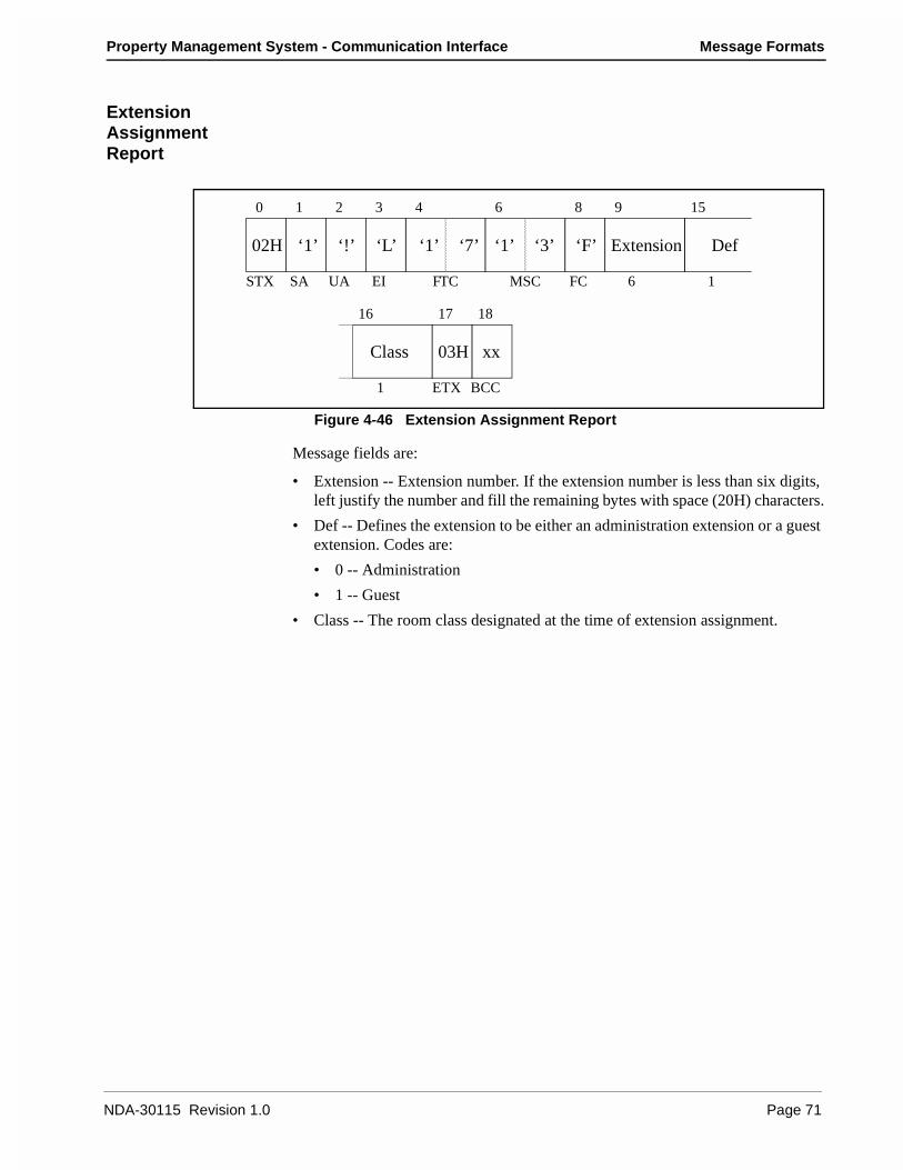
Property Management System - Communication Interface Message Formats
Extension Assignment Report
Figure 4-46 Extension Assignment Report
Message fields are:
• Extension -- Extension number. If the extension number is less than six digits, left justify the number and fill the remaining bytes with space (20H) characters.
• Def -- Defines the extension to be either an administration extension or a guest extension. Codes are:
• 0 -- Administration
• 1 -- Guest
• Class -- The room class designated at the time of extension assignment.
‘1’ ‘7’ ‘1’ ‘3’ ‘F’ Extension Def
Class
0 1 2 3 4 6 8 9 15
STX SA UA EI FTC MSC FC 6 1
02H ‘1’ ‘!’ ‘L’
03H xx
ETX BCC1
16 17 18
NDA-30115 Revision 1.0 Page 71
Message Formats Property Management System - Communication Interface
Room Recovery (Model 60)
These messages are used by the PMS to update the database in the Model 60 version of the NEAX. First a Recovery Start Report (70-3) is sent. Then, one or more sets of Room Image messages are sent. Finally, a Recovery End Report (70-4) is sent.
The messages are grouped into a set of four messages. Within each set of four messages the format of the messages is identical, except for the Function Codes, which specify the message. Each set of messages contain more fields (and can therefore convey more information) than the preceding set.
Each set of four messages is itself a set of two pairs of messages. The first pair of messages is used when the PMS, in normal operation (i.e. not error recovery), needs to update the information on a given extension. The second pair of messages is used during recovery. This pair will only be used in response to the NEAX sending a Nop Test Recover Answer or Recovery Request message.
The first message (of either pair) is used by the PMS as an update/ request for information on an extension. If a field contains a valid entry, the NEAX database is updated; if the field is entirely filled with NULL (00H) characters, it is a request for the NEAX to send the value from the NEAX database. The second message is the response from the NEAX to the PMS.
• 17-1 -- Room Image Set 1 (Normal Request from PMS)
• 17-2 -- Room Image Set 1 (Normal Answer from NEAX)
• 17-3 -- Room Image Set 1 (Recovery Request from PMS)
• 17-4 -- Room Image Set 1 (Recovery Answer from NEAX)
• 17-5 -- Room Image Set 2 (Normal Request from PMS)
• 17-6 -- Room Image Set 2 (Normal Answer from NEAX)
• 17-7 -- Room Image Set 2 (Recovery Request from PMS)
• 17-8 -- Room Image Set 2 (Recovery Answer from NEAX)
• 17-9 -- Room Image Set 3 (Normal Request from PMS)
• 17-A -- Room Image Set 3 (Normal Answer from NEAX)
• 17-B -- Room Image Set 3 (Recovery Request from PMS)
• 17-C -- Room Image Set 3 (Recovery Answer from NEAX)
Page 72 NDA-30115 Revision 1.0

Property Management System - Communication Interface Message Formats
Room Image Set 1
Figure 4-47 Room Image Set 1
The message fields are:
• FC -- Function Codes that use this message format are: (FTC-FC)
• 17-1 -- Room Image Set 1 (Normal Request from PMS)
• 17-2 -- Room Image Set 1 (Normal Answer from NEAX)
• 17-3 -- Room Image Set 1 (Recovery Request from PMS)
• 17-4 -- Room Image Set 1 (Recovery Answer from NEAX)
• Extension -- Extension number. If the extension number is less than six digits, left justify the number and fill the remaining bytes with space (20H) characters.
• Vacancy -- Vacancy/Occupancy flag. The possible values are:
• 0 -- Vacant.
• 1 -- Occupied.
• Status - Message Waiting status. The possible values are:
• 0 -- Message Waiting Lamp is off.
• 1 -- Message Waiting Lamp is on.
• Code -- Restriction code for this extension. The possible codes are:
• 0 -- Do Not Disturb and Room Cut-Off are cancelled.
• 1 -- Room Cut-Off is set, Do Not Disturb is cancelled.
• 5 -- Do Not Disturb is set, Room Cut-Off is cancelled.
• 6 -- Do Not Disturb and Room Cut-Off are set.
• Blank -- Field contains 14 space (20H) characters.
‘1’ ‘7’ ‘2’ ‘8’ ** Extension Vacancy
Status Code Blank
** Multiple Function Codes use this message. See below.
0 1 2 3 4 6 8 9 15
STX SA UA EI FTC MSC FC 6 1
02H ‘1’ ‘!’ ‘L’
03H xx
ETX BCC1 1 14
16 17 18 32 33
NDA-30115 Revision 1.0 Page 73
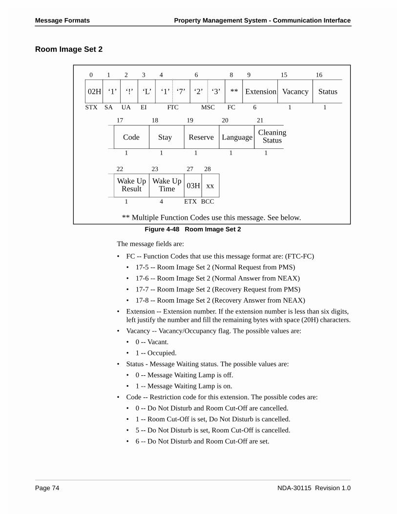
Message Formats Property Management System - Communication Interface
Room Image Set 2
Figure 4-48 Room Image Set 2
The message fields are:
• FC -- Function Codes that use this message format are: (FTC-FC)
• 17-5 -- Room Image Set 2 (Normal Request from PMS)
• 17-6 -- Room Image Set 2 (Normal Answer from NEAX)
• 17-7 -- Room Image Set 2 (Recovery Request from PMS)
• 17-8 -- Room Image Set 2 (Recovery Answer from NEAX)
• Extension -- Extension number. If the extension number is less than six digits, left justify the number and fill the remaining bytes with space (20H) characters.
• Vacancy -- Vacancy/Occupancy flag. The possible values are:
• 0 -- Vacant.
• 1 -- Occupied.
• Status - Message Waiting status. The possible values are:
• 0 -- Message Waiting Lamp is off.
• 1 -- Message Waiting Lamp is on.
• Code -- Restriction code for this extension. The possible codes are:
• 0 -- Do Not Disturb and Room Cut-Off are cancelled.
• 1 -- Room Cut-Off is set, Do Not Disturb is cancelled.
• 5 -- Do Not Disturb is set, Room Cut-Off is cancelled.
• 6 -- Do Not Disturb and Room Cut-Off are set.
Vacancy
Stay Reserve LanguageCleaning
Wake UpWake Up
** Multiple Function Codes use this message. See below.
Status
Result
Status
Time
‘1’ ‘7’ ‘2’ ‘3’ ** Extension
0 1 2 3 4 6 8 9 15 16
STX SA UA EI FTC MSC FC 6 1 1
02H ‘1’ ‘!’ ‘L’
03H xx
ETX BCC
1 1 1 1 1
17 18 19 20 21
Code
22 23 27 28
1 4
Page 74 NDA-30115 Revision 1.0
Property Management System - Communication Interface Message Formats
• Stay -- Room stay. The possible values are listed below:
• Reserve -- Reserve flag. Possible values are:
• 0 -- Room is not reserved
• 1 -- Room is reserved.
• Language -- Language category for the guest. The possible values are:
• 0 -- Not specified
• 1 -- Japanese
• 2 -- English
• 3 -- German
• 4 -- French
• 5 -- Spanish
• 6 -- Chinese
• 7 -- Russian.
• Cleaning Status -- The possible values are:
• 1 -- Cleaning Started
• 2 -- Cleaning Ended
• 3 -- Cleaning Check Ended.
• Wake Up Result -- This indicates the result of the wake up call. The possible values are:
• 1 -- Answer
• 2 -- Busy
• 3 -- No Answer
• 4 -- Block
• 5 -- Call Termination to Attendant Console
• Wake Up Time -- The time for which the wake up call is set. Format used is HHMM using military time.
Stay1234
VIPNoYesNoYes
OutNo (Key is not in key rack.)No (Key is not in key rack.)Yes (Key is in key rack.)Yes (Key is in key rack.)
NDA-30115 Revision 1.0 Page 75
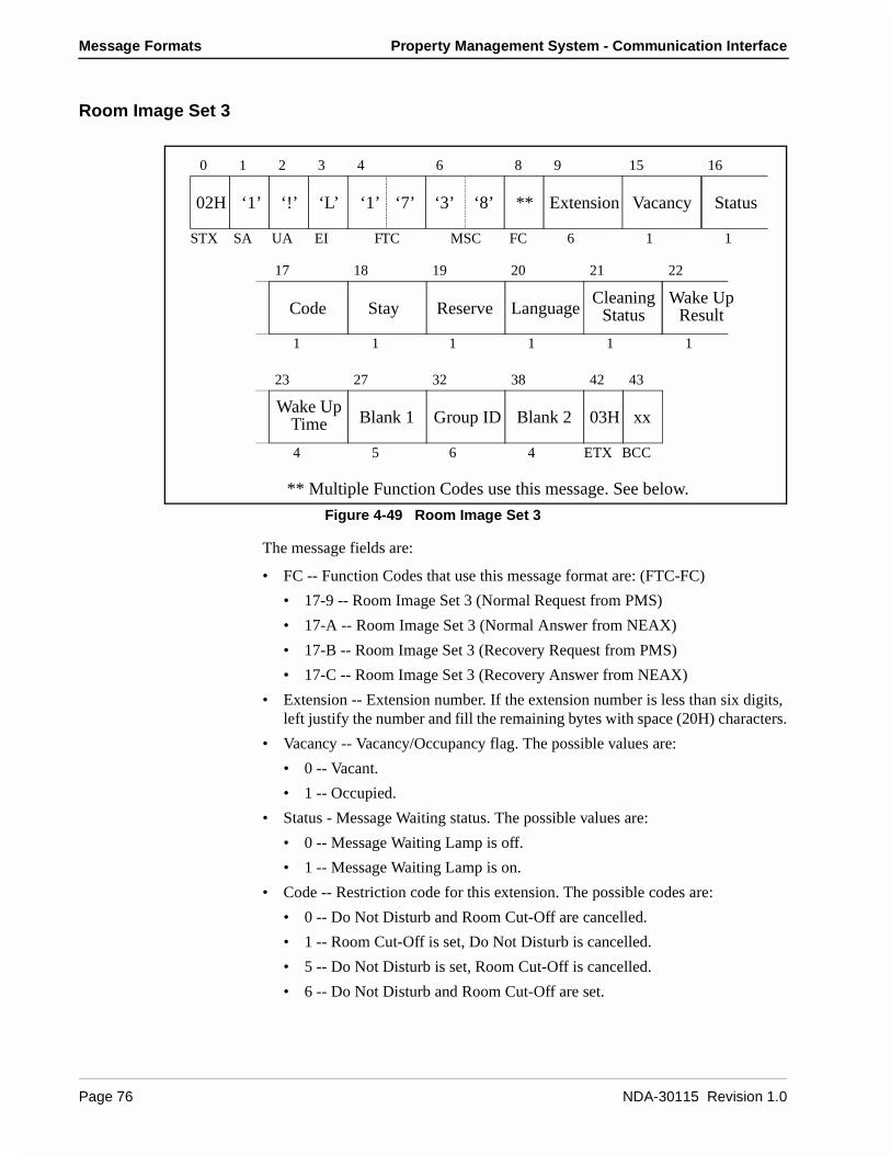
Message Formats Property Management System - Communication Interface
Room Image Set 3
Figure 4-49 Room Image Set 3
The message fields are:
• FC -- Function Codes that use this message format are: (FTC-FC)
• 17-9 -- Room Image Set 3 (Normal Request from PMS)
• 17-A -- Room Image Set 3 (Normal Answer from NEAX)
• 17-B -- Room Image Set 3 (Recovery Request from PMS)
• 17-C -- Room Image Set 3 (Recovery Answer from NEAX)
• Extension -- Extension number. If the extension number is less than six digits, left justify the number and fill the remaining bytes with space (20H) characters.
• Vacancy -- Vacancy/Occupancy flag. The possible values are:
• 0 -- Vacant.
• 1 -- Occupied.
• Status - Message Waiting status. The possible values are:
• 0 -- Message Waiting Lamp is off.
• 1 -- Message Waiting Lamp is on.
• Code -- Restriction code for this extension. The possible codes are:
• 0 -- Do Not Disturb and Room Cut-Off are cancelled.
• 1 -- Room Cut-Off is set, Do Not Disturb is cancelled.
• 5 -- Do Not Disturb is set, Room Cut-Off is cancelled.
• 6 -- Do Not Disturb and Room Cut-Off are set.
Blank 1
Cleaning Wake UpResultStatus
Group ID Blank 2
** Multiple Function Codes use this message. See below.
Vacancy
Stay Reserve Language
Wake Up
Status
Time
‘1’ ‘7’ ‘3’ ‘8’ ** Extension
0 1 2 3 4 6 8 9 15 16
STX SA UA EI FTC MSC FC 6 1 1
02H ‘1’ ‘!’ ‘L’
ETX BCC
1 1 1 1 1 1
17 18 19 20 21 22
Code
23 27 32 38 42 43
4 5 6 4
03H xx
Page 76 NDA-30115 Revision 1.0

Property Management System - Communication Interface Message Formats
• Stay -- Room stay. The possible values are listed below:
• Reserve -- Reserve flag. Possible values are:
• 0 -- Room is not reserved
• 1 -- Room is reserved.
• Language -- Language category for the guest. The possible values are:
• 0 -- Not specified
• 1 -- Japanese
• 2 -- English
• 3 -- German
• 4 -- French
• 5 -- Spanish
• 6 -- Chinese
• 7 -- Russian.
• Cleaning Status -- The possible values are:
• 1 -- Cleaning Started
• 2 -- Cleaning Ended
• 3 -- Cleaning Check Ended.
• Wake Up Result -- This indicates the result of the wake up call. The possible values are:
• 1 -- Answer
• 2 -- Busy
• 3 -- No Answer
• 4 -- Block
• 5 -- Call Termination to Attendant Console
• Wake Up Time -- The time for which the wake up call is set. Format used is HHMM using military time.
• Blank 1 -- Field contains five space (20H) characters.
• Group ID -- Group number for the extension. If the group number is less than six digits, left justify the number and fill the remaining bytes with space (20H) characters.
• Blank 2 -- Field contains four space (20H) characters.
Stay1234
VIPNoYesNoYes
OutNo (Key is not in key rack.)No (Key is not in key rack.)Yes (Key is in key rack.)Yes (Key is in key rack.)
NDA-30115 Revision 1.0 Page 77

Message Formats Property Management System - Communication Interface
Room Recovery (Model 90)
These messages are only used by the Model 90. When the PMS receives a Nop Test Recover Answer (70-2) message, it sends one Room Data Report message for each room. Prior to sending any recovery messages, however, a Recovery Start Report (70-3) must first be sent. Recovery is concluded by sending a Recovery End Report (70-4).
The Room Recovery messages use the following Function Codes:
• 57-1 -- Room Data Report
• 57-3 -- Guest Room Secretary Telephone
• 57-4 -- Connecting Room
• 57-5 -- Message Status Report
• 57-6 -- Wake Up
Room Data Report
Figure 4-50 Room Data Report
If Room Status is set to ‘0’ and Cleaning Status is set to either ‘3’ or ‘4’, the room data is cleared.
The message fields are:
• Extension -- Extension number. If the extension number is less than six digits, left justify the number and fill the remaining bytes with space (20H) characters.
• Group ID -- Group number for the extension. If the group number is less than six digits, left justify the number and fill the remaining bytes with space (20H) characters.
• Room Status -- Room status. This flag is used in conjunction with the cleaning status flag to determine the status of the room.
‘5’ ‘7’ ‘4’ ‘6’ ‘1’ Extension Group ID
Key VIP LanguageDisplay
Data BData A
RoomStatus
0 1 2 3 4 6 8 9 15 21
STX SA UA EI FTC MSC FC 6 6 1
02H ‘1’ ‘!’ ‘L’
03H xx
ETX BCC
1 1 1 1 16
22 23 24 25 26
42 45 50 51
3 5
NameCleaning
Status
Page 78 NDA-30115 Revision 1.0
Property Management System - Communication Interface Message Formats
• Cleaning Status -- Cleaning status. The possible combinations with room status are listed below:
• Key -- Room key status:
• 0 -- Key is in the key rack.
• 1 -- Key is not in the key rack.
• VIP -- VIP category:
• 0 -- Guest is not a VIP.
• 1 -- Guest is a VIP.
• Language -- Language category for the guest. The possible values are:
• 0 -- Not specified
• 1 -- Japanese
• 2 -- English
• 3 -- German
• 4 -- French
• 5 -- Spanish
• 6 -- Chinese
• 7 -- Russian.
• Display Name -- The display name of the guest. The name must be left justified, and any remaining space must be filled with space (20H) characters.
• Data A & B-- Condition Data A and B. The contents of the option data are to be assigned on an individual hotel basis.
220000
010124
Stay, Departure DayStay, Departure Day, Cleaning in progressOut (Checked Out)Out, Cleaning in progressOut, Cleaning endedOut of Order (Cannot sell)
Room011
Clean301
Status of the RoomVacant (Ready to sell)Stay (Occupied)Stay, Cleaning in progress
11
23
Stay, Cleaning endedStay, Inspected
NDA-30115 Revision 1.0 Page 79

Message Formats Property Management System - Communication Interface
Guest Room Secretary Telephone
Figure 4-51 Guest Room Secretary Telephone
The message fields are:
• Boss -- Extension number of the boss. If the extension number is less than six digits, left justify the number and fill the remaining bytes with space (20H) characters.
• Secty -- Extension number of the secretary. The secretary’s extension is now associated with the boss’s extension. If the extension number is less than six digits, left justify the number and fill the remaining bytes with space (20H) characters.
Connecting Room
Figure 4-52 Connecting Room
The message fields are:
• Master -- Extension number of the master extension. If the extension number is less than six digits, left justify the number and fill the remaining bytes with space (20H) characters.
• Secondary -- Extension number of the secondary extension. The secondary extension is now associated with the master extension. If the extension number is less than six digits, left justify the number and fill the remaining bytes with space (20H) characters.
‘5’ ‘7’ ‘1’ ‘7’ ‘3’ Boss Secty
0 1 2 3 4 6 8 9 15 21 22
STX SA UA EI FTC MSC FC 6 6
02H ‘1’ ‘!’ ‘L’ 03H xx
ETX BCC
‘5’ ‘7’ ‘1’ ‘7’ ‘4’ Master Secondary
0 1 2 3 4 6 8 9 15 21 22
STX SA UA EI FTC MSC FC 6 6
02H ‘1’ ‘!’ ‘L’ 03H xx
ETX BCC
Page 80 NDA-30115 Revision 1.0

Property Management System - Communication Interface Message Formats
Message Status Report
Figure 4-53 Message Status Report
The message fields are:
• Extension -- Extension number. If the extension number is less than six digits, left justify the number and fill the remaining bytes with space (20H) characters.
• Status -- Message Waiting Lamp status. The status values are:
• 0 -- No text messages waiting.
• 1 -- Message waiting set by the NEAX.
• 4 -- Message waiting set by the PMS.
• 5 -- Message waiting set by the PMS and the NEAX.
• Option -- Message Waiting status option. This field must always contain zero (‘0’).
• VMC -- This is reserved for future use. Should be filled with two space (20H) characters.
‘5’ ‘7’ ‘1’ ‘5’ ‘5’ Extension Status
Option VMC
0 1 2 3 4 6 8 9 15
STX SA UA EI FTC MSC FC 6 1
02H ‘1’ ‘!’ ‘L’
03H xx
ETX BCC1 2
16 17 19 20
NDA-30115 Revision 1.0 Page 81

Message Formats Property Management System - Communication Interface
Wake Up
Figure 4-54 Wake Up
The message fields are:
• Extension -- Extension number. If the extension number is less than six digits, left justify the number and fill the remaining bytes with space (20H) characters.
• Time -- Time for which a wake up call is set. Format used is HHMM using military time.
• Blank -- A single space (20H) character.
Direct Data Entry (Model 90)
These messages are used to allow numeric information to be entered through a guest room telephone and then be sent directly to the PMS. The three messages used are:
• 59-1 -- Direct Data Entry
• 59-8 -- Direct Data Entry Negative Answer
• 59-9 -- Direct Data Entry Positive Answer
‘5’ ‘7’ ‘1’ ‘6’ ‘6’ Extension Time
Blank
0 1 2 3 4 6 8 9 15
STX SA UA EI FTC MSC FC 6 4
02H ‘1’ ‘!’ ‘L’
03H xx
ETX BCC1
19 20 21
Page 82 NDA-30115 Revision 1.0

Property Management System - Communication Interface Message Formats
Direct Data Entry
Figure 4-55 Direct Data Entry
• Extension -- Extension number. If the extension number is less than six digits, left justify the number and fill the remaining bytes with space (20H) characters.
• Numeric Input -- Numeric information entered after the special access code.
• LEN -- Line Equipment Number of the extension.
Direct Data Entry Answer
Figure 4-56 Direct Data Entry Answer
The message fields are:
• FC -- Function Codes that use this message format are: (FTC-FC)
• 59-8 -- Direct Data Entry Negative Answer
• 59-9 -- Direct Data Entry Positive Answer
• Extension -- Extension number. If the extension number is less than six digits, left justify the number and fill the remaining bytes with space (20H) characters.
• LEN -- Line Equipment Number of the extension.
‘5’ ‘9’ ‘4’ ‘7’ ‘1’ ExtensionNumeric
Input
0 1 2 3 4 6 8 9 15
STX SA UA EI FTC MSC FC 6 30
02H ‘1’ ‘!’ ‘L’
xx
ETX BCC6
45 51 52
03HLEN
‘5’ ‘9’ ‘1’ ‘7’ ** Extension LEN
0 1 2 3 4 6 8 9 15 21 22
STX SA UA EI FTC MSC FC 6 6
02H ‘1’ ‘!’ ‘L’ 03H xx
ETX BCC
** Multiple Function Codes use this message. See below.
NDA-30115 Revision 1.0 Page 83
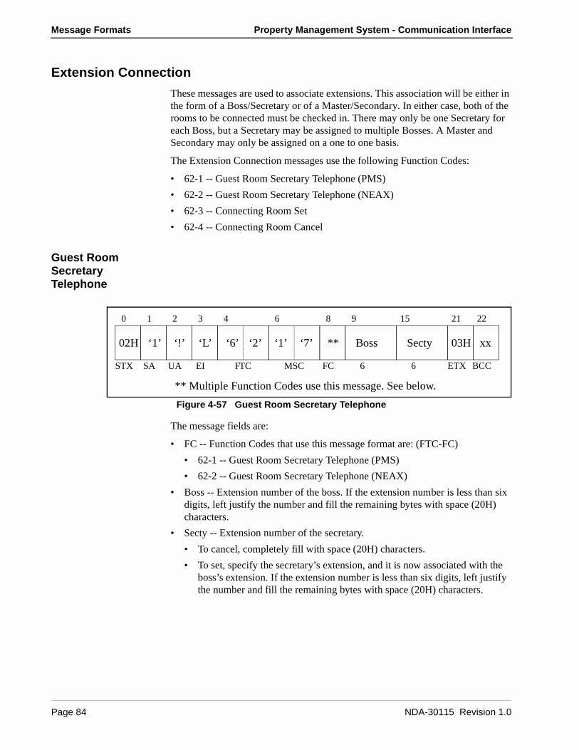
Message Formats Property Management System - Communication Interface
Extension Connection
These messages are used to associate extensions. This association will be either in the form of a Boss/Secretary or of a Master/Secondary. In either case, both of the rooms to be connected must be checked in. There may only be one Secretary for each Boss, but a Secretary may be assigned to multiple Bosses. A Master and Secondary may only be assigned on a one to one basis.
The Extension Connection messages use the following Function Codes:
• 62-1 -- Guest Room Secretary Telephone (PMS)
• 62-2 -- Guest Room Secretary Telephone (NEAX)
• 62-3 -- Connecting Room Set
• 62-4 -- Connecting Room Cancel
Guest Room Secretary Telephone
Figure 4-57 Guest Room Secretary Telephone
The message fields are:
• FC -- Function Codes that use this message format are: (FTC-FC)
• 62-1 -- Guest Room Secretary Telephone (PMS)
• 62-2 -- Guest Room Secretary Telephone (NEAX)
• Boss -- Extension number of the boss. If the extension number is less than six digits, left justify the number and fill the remaining bytes with space (20H) characters.
• Secty -- Extension number of the secretary.
• To cancel, completely fill with space (20H) characters.
• To set, specify the secretary’s extension, and it is now associated with the boss’s extension. If the extension number is less than six digits, left justify the number and fill the remaining bytes with space (20H) characters.
‘6’ ‘2’ ‘1’ ‘7’ ** Boss Secty
0 1 2 3 4 6 8 9 15 21 22
STX SA UA EI FTC MSC FC 6 6
02H ‘1’ ‘!’ ‘L’ 03H xx
ETX BCC
** Multiple Function Codes use this message. See below.
Page 84 NDA-30115 Revision 1.0
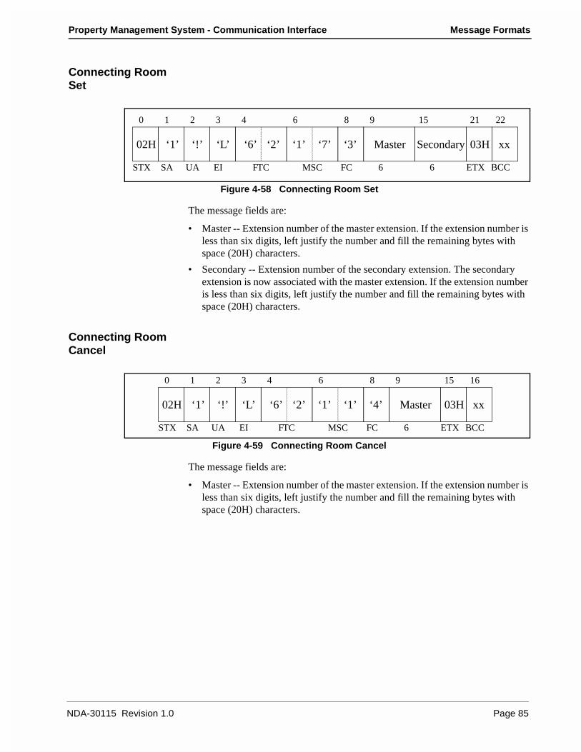
Property Management System - Communication Interface Message Formats
Connecting Room Set
Figure 4-58 Connecting Room Set
The message fields are:
• Master -- Extension number of the master extension. If the extension number is less than six digits, left justify the number and fill the remaining bytes with space (20H) characters.
• Secondary -- Extension number of the secondary extension. The secondary extension is now associated with the master extension. If the extension number is less than six digits, left justify the number and fill the remaining bytes with space (20H) characters.
Connecting Room Cancel
Figure 4-59 Connecting Room Cancel
The message fields are:
• Master -- Extension number of the master extension. If the extension number is less than six digits, left justify the number and fill the remaining bytes with space (20H) characters.
‘6’ ‘2’ ‘1’ ‘7’ ‘3’ Master Secondary
0 1 2 3 4 6 8 9 15 21 22
STX SA UA EI FTC MSC FC 6 6
02H ‘1’ ‘!’ ‘L’ 03H xx
ETX BCC
‘6’ ‘2’ ‘1’ ‘1’ ‘4’ Master
0 1 2 3 4 6 8 9 15 16
STX SA UA EI FTC MSC FC 6
02H ‘1’ ‘!’ ‘L’ 03H xx
ETX BCC
NDA-30115 Revision 1.0 Page 85
Message Formats Property Management System - Communication Interface
This Page Left Blank.
Page 86 NDA-30115 Revision 1.0

Property Management System - Communication Interface References
Chapter 5 References
The following document was used to prepare this specification:
• NEAX2400 IMS Hotel System PMS Interface Specification (4252/4253/5250 Feature Package), ND-90265 (E)
NDA-30115 Revision 1.0 Page 87
References Property Management System - Communication Interface
This Page Left Blank.
Page 88 NDA-30115 Revision 1.0
Property Management System - Communication Interface Glossary
Chapter 6 Glossary
BCC Block Check Code. Computed by an exclusive OR of the message from the SA field to the ETX character, inclusive. This is used to assist in error control.
EI Entry Index. Always ‘L’ for the PMS interface.
ETX End of Text. Special control character used to denote the end of a message block. Always 03H.
FC Function Code. Identifies a specific message within a feature code. The combination of feature code and function code uniquely identifies each message. See Appendix C for a list of codes.
FTC Feature Code. Identifies a set of related messages. See Appendix B for a list of codes.
MSC Message Counter. Specifies the length of the significant data in a message. The count begins with the FTC field and ends at the last character of the body (prior to the ETX character). The count includes the MSC field, which is always two characters.
MWL Message Waiting Lamp.
NEAX The NEAX2400 IMS system. It is a private branch exchange, which is a digital voice and data communication system for the office.
PMS Property Management System. A set of software and hardware which manages a hotel’s assets.
SA System Address. Always ‘1’ for the PMS interface.
STX Start of Text. Special control character used to denote the start of a message block. Always 02H.
Suite Room This is an optional feature of the NEAX that enables a group of extensions to be treated as the same extension in a room. Messages refer to all extensions in a suite by means of the suite’s primary extension.
UA Unit Address. Always ‘!’ for the PMS interface.
Violation Code This is a special FTC that ranges from 80H to FFH. It identifies a message from the PMS that the PBX (or UAP) has rejected for some reason. The FTC of the original message, subtract 80H from the violation code. The body of the original message is unchanged.
NDA-30115 Revision 1.0 Page 89

Glossary Property Management System - Communication Interface
This Page Left Blank.
Page 90 NDA-30115 Revision 1.0
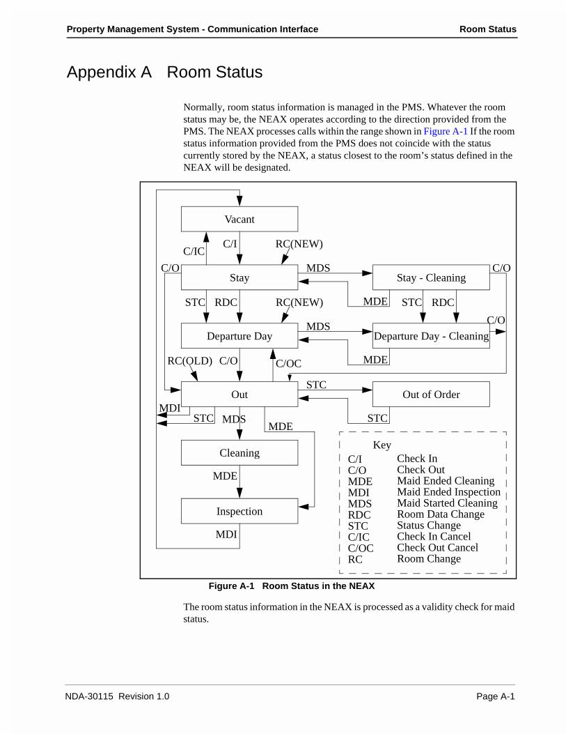
Property Management System - Communication Interface Room Status
Appendix A Room Status
Normally, room status information is managed in the PMS. Whatever the room status may be, the NEAX operates according to the direction provided from the PMS. The NEAX processes calls within the range shown in Figure A-1 If the room status information provided from the PMS does not coincide with the status currently stored by the NEAX, a status closest to the room’s status defined in the NEAX will be designated.
Figure A-1 Room Status in the NEAX
The room status information in the NEAX is processed as a validity check for maid status.
Departure Day - Cleaning
Vacant
Out
Departure Day
Stay
Out of Order
Stay - Cleaning
Inspection
CleaningC/IC/OMDEMDIMDSRDCSTCC/ICC/OCRC
C/I
C/O
MDE
MDI
MDS
RDCSTC
C/IC
C/OCRC(OLD)
C/O
MDE
MDI
MDS
STC
STC
STC
STC
RDC
C/O
C/O
MDE
MDE
MDS
RC(NEW)
RC(NEW)
Check InCheck OutMaid Ended CleaningMaid Ended InspectionMaid Started CleaningRoom Data ChangeStatus ChangeCheck In CancelCheck Out CancelRoom Change
Key
NDA-30115 Revision 1.0 Page A-1
Room Status Property Management System - Communication Interface
Updating Room Status Information in the NEAX
The messages containing room status information, sent from the PMS, are as follows:
Check In: 16-1, 16-A, 16-B, 56-1
Check Out: 16-2, 56-2
Room Change: 20-1, 56-6
Room Data Image: 17-3, 17-7, 17-B
Maid Status Answer: 51-9
Check In Cancel: 56-4
Room Data Change: 61-1
Room Status Change: 61-3
Check Out Cancel: 56-5
Recovery Room Data Report: 57-1.
When updating the room status from the NEAX side, the update is performed as follows:
The validity of maid status messages (11-1, 11-2, 11-3, 12-1, 12-2, 12-3) is checked by the room status stored in the NEAX. After the status of the room has been updated, maid status messages are sent out to the PMS.
Maid Status Answer Back System: maid status messages are sent out to the PMS. The PMS will then check the validity of the messages and provide either a positive or negative result to the NEAX. This is used in Model 90 only.
For messages in Model 90, the Room Status field and the Cleaning Status field are provided so that details can be directed to the PMS. If certain hotels do not utilize maid status for their applications, the status can be designated as Vacant in the Check Out message.
Clearing Room Data
The NEAX will clear the room data when the PMS sets the status of the room to “Vacant (Room Status=0, Cleaning Status=3)” or “Out of Order (Room Status=0, Cleaning Status=4)”. (Note: Group Registration is cleared at the time of Check Out.) Therefore, in a hotel where the PMS does not provide maid status, the PMS must use a Check Out message to make the status of the room become “Vacant”, and thus clear the room data.
Dial Steps for Maid Status
A choice of three dialing patterns is available for Maid Status in the NEAX. Whichever pattern is selected, the “Inspection End” step must be included.
Dial Steps Pattern 1 Pattern 2 Pattern3
Cleaning Start 1 - -
Cleaning End 2 1 -
Page A-2 NDA-30115 Revision 1.0
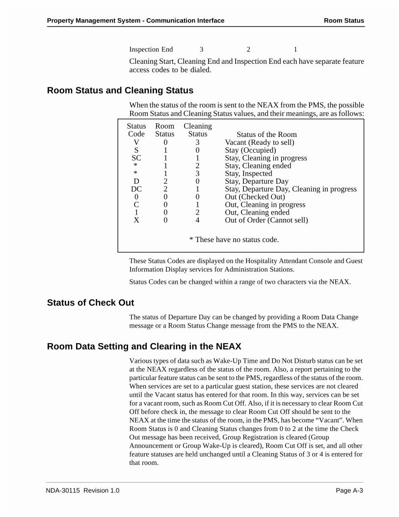
Property Management System - Communication Interface Room Status
Inspection End 3 2 1
Cleaning Start, Cleaning End and Inspection End each have separate featureaccess codes to be dialed.
Room Status and Cleaning Status
When the status of the room is sent to the NEAX from the PMS, the possibleRoom Status and Cleaning Status values, and their meanings, are as follows:
These Status Codes are displayed on the Hospitality Attendant Console and Guest Information Display services for Administration Stations.
Status Codes can be changed within a range of two characters via the NEAX.
Status of Check Out
The status of Departure Day can be changed by providing a Room Data Change message or a Room Status Change message from the PMS to the NEAX.
Room Data Setting and Clearing in the NEAX
Various types of data such as Wake-Up Time and Do Not Disturb status can be set at the NEAX regardless of the status of the room. Also, a report pertaining to the particular feature status can be sent to the PMS, regardless of the status of the room. When services are set to a particular guest station, these services are not cleared until the Vacant status has entered for that room. In this way, services can be set for a vacant room, such as Room Cut Off. Also, if it is necessary to clear Room Cut Off before check in, the message to clear Room Cut Off should be sent to the NEAX at the time the status of the room, in the PMS, has become “Vacant”. When Room Status is 0 and Cleaning Status changes from 0 to 2 at the time the Check Out message has been received, Group Registration is cleared (Group Announcement or Group Wake-Up is cleared), Room Cut Off is set, and all other feature statuses are held unchanged until a Cleaning Status of 3 or 4 is entered for that room.
220000
010124
Stay, Departure DayStay, Departure Day, Cleaning in progressOut (Checked Out)Out, Cleaning in progressOut, Cleaning endedOut of Order (Cannot sell)
Room
011
Cleaning
301
Status of the RoomVacant (Ready to sell)Stay (Occupied)Stay, Cleaning in progress
11
23
Stay, Cleaning endedStay, Inspected
DDC0C1X
Status
VS
SC* *
Status StatusCode
* These have no status code.
NDA-30115 Revision 1.0 Page A-3
Room Status Property Management System - Communication Interface
Page A-4 NDA-30115 Revision 1.0
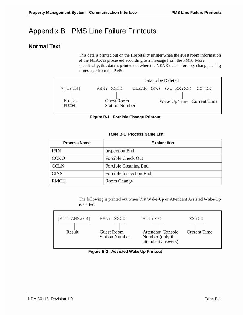
Property Management System - Communication Interface PMS Line Failure Printouts
Appendix B PMS Line Failure Printouts
Normal Text
This data is printed out on the Hospitality printer when the guest room information of the NEAX is processed according to a message from the PMS. More specifically, this data is printed out when the NEAX data is forcibly changed using a message from the PMS.
Figure B-1 Forcible Change Printout
The following is printed out when VIP Wake-Up or Attendant Assisted Wake-Up is started.
Figure B-2 Assisted Wake Up Printout
ProcessName
Guest RoomStation Number
RSN: XXXX
Data to be Deleted
CLEAR (MW) (WU XX:XX)
Current Time
XX:XX*[IFIN]
Wake Up Time
Table B-1 Process Name List
Process Name Explanation
IFIN Inspection End
CCKO Forcible Check Out
CCLN Forcible Cleaning End
CINS Forcible Inspection End
RMCH Room Change
[ATT ANSWER] RSN: XXXX ATT:XXX XX:XX
Guest RoomStation Number
Attendant ConsoleNumber (only ifattendant answers)
Current TimeResult
NDA-30115 Revision 1.0 Page B-1

PMS Line Failure Printouts Property Management System - Communication Interface
Abnormal Events
When the NEAX receives a message from the PMS, and the received data is abnormal or it cannot be processed by the NEAX, the message is printed out.
Figure B-3 Abnormal Events Printout
Abnormal Port
If an external port of the NEAX is in an abnormal state, the abnormality will be printed out.
Figure B-4 Abnormal Port Printout
Table B-2 Wake Up Results
Wake Up Results Explanation
ATT ANSWER Attendant Console answers.
ATT CALLED Attendant Console has been called.
ATT CALLING: ROOM STA ANSWER While Attendant Console is calling, a guest room station has answered.
ATT NO ANSWER: ROOM STA CALLED An Attendant Console has not answered, a guest room station has been called.
ROOM STA BUSY A guest room station is currently on a call.
Entry Error
[XX-X] INPUT ERR XXXXXXXXXXXXXXXX... XX:XX
Message DataError Number: Current Time
HP Task Error[EXXX] HI=XX XX XX XX XX ... XX:XX
Current TimeData to be processedTask Error Number
FTC-FC of return violation code
[I/O PKG NOT READY] PORT NO = X STATUS = XX XX XX XX XX:XX
Failure Type Port Number Port State Current Time
Page B-2 NDA-30115 Revision 1.0

Property Management System - Communication Interface PMS Line Failure Printouts
Figure B-5 Port State
Table B-3 Types of Failure
Failure Type Explanation
I/O PKG NOT READY The I/O package is not mounted, or it is in the make-busy state.
DR OFF/TX NOT RDY The data-ready has switched off during transmission. Does not become clear-to-send during transmission.
SINQ STOP/S-120 The status inquiry message has stopped.
LINE SUP. TIMEOUT The monitor timer of the transmission supervisory program timed out, then restarted.
RCV SEQUENCE ERR. A line control code which is invalid in reception processing has been received.
DATA LINK NOT RDY Data-ready read has switched off.
SINQ TO/120 DOWN System connection failure has been judged five minutes after SINQ STOP.
SND SEQUENCE ERR. A line control code which is invalid in transmission process-ing has been received.
DTR OFF REQUESTED Request to disconnect line from the connected system has been received.
S-120 STOP (MENT) Indicates stoppage due to request to disconnect line from the connected system.
LINK CLOSE (MENT) Line, package, etc. have been pulled out after requesting to disconnect line.
XX XX XX XX
I/O port status
FIFO status scan data
I/O port status scan data
NDA-30115 Revision 1.0 Page B-3
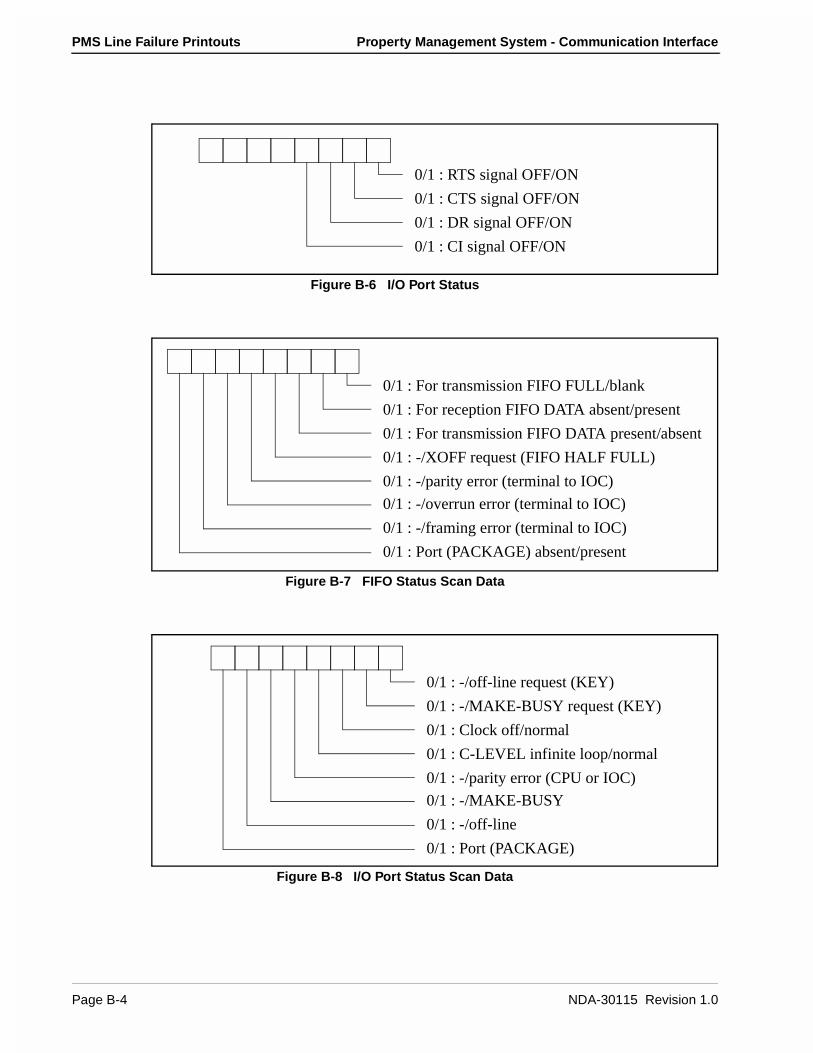
PMS Line Failure Printouts Property Management System - Communication Interface
Figure B-6 I/O Port Status
Figure B-7 FIFO Status Scan Data
Figure B-8 I/O Port Status Scan Data
0/1 : RTS signal OFF/ON
0/1 : CTS signal OFF/ON
0/1 : DR signal OFF/ON
0/1 : CI signal OFF/ON
0/1 : For transmission FIFO FULL/blank
0/1 : For reception FIFO DATA absent/present
0/1 : For transmission FIFO DATA present/absent
0/1 : -/XOFF request (FIFO HALF FULL)
0/1 : -/parity error (terminal to IOC)
0/1 : -/overrun error (terminal to IOC)
0/1 : -/framing error (terminal to IOC)
0/1 : Port (PACKAGE) absent/present
0/1 : -/off-line request (KEY)
0/1 : -/MAKE-BUSY request (KEY)
0/1 : Clock off/normal
0/1 : C-LEVEL infinite loop/normal
0/1 : -/parity error (CPU or IOC)
0/1 : -/MAKE-BUSY
0/1 : -/off-line
0/1 : Port (PACKAGE)
Page B-4 NDA-30115 Revision 1.0
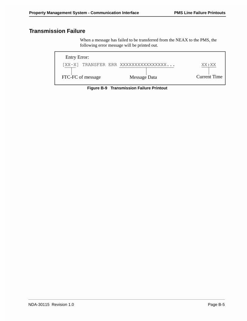
Property Management System - Communication Interface PMS Line Failure Printouts
Transmission Failure
When a message has failed to be transferred from the NEAX to the PMS, the following error message will be printed out.
Figure B-9 Transmission Failure Printout
Entry Error:
[XX-X] TRANSFER ERR XXXXXXXXXXXXXXXX... XX:XX
Message DataFTC-FC of message Current Time
NDA-30115 Revision 1.0 Page B-5
PMS Line Failure Printouts Property Management System - Communication Interface
This Page Left Blank.
Page B-6 NDA-30115 Revision 1.0

Property Management System - Communication Interface Feature Codes
Appendix C Feature Codes
Feature Code Description
70 Data Link Maintenance
11, 12, 51, 52 Maid Status
13, 53 Message Waiting Lamp Control
15 Restriction Control
16 Check-In/Out (Model 60)
56 Check-In/Out (Model 90)
17 Extension Report
17 Room Recovery (Model 60)
57 Room Recovery (Model 90)
19 Wake Up/Group Announcement
20 Room Move/Swap/Copy (Model 60)
21, 61 Room Data Change
59 Direct Data Entry (Model 90)
62 Extension Connection
NDA-30115 Revision 1.0 Page C-1

Feature Codes Property Management System - Communication Interface
This Page Left Blank.
Page C-2 NDA-30115 Revision 1.0

Property Management System - Communication Interface Function Codes
Appendix D Function Codes
FTC FC Description Source Model
70 0 Nop Test Normal Answer NEAX ALL
70 2 Nop Test Recover Answer NEAX ALL
70 3 Recovery Start Report PMS ALL
70 4 Recovery End Report PMS ALL
70 5 Data Link Release Request PMS/NEAX ALL
70 6 Data Link Release Confirmation PMS/NEAX ALL
70 8 Extension Number Request PMS ALL
70 F Nop Test PMS ALL
11 1 Cleaning Start (Guest) NEAX ALL
11 2 Cleaning End (Guest) NEAX ALL
11 3 Inspection End (Guest) NEAX ALL
11 4 Out of Order (Guest) NEAX ALL
12 1 Cleaning Start (Administration) NEAX ALL
12 2 Cleaning End (Administration) NEAX ALL
12 3 Inspection End (Administration) NEAX ALL
51 1 Guest Room 1 NEAX 90
51 2 Guest Room 2 NEAX 90
51 3 Guest Room 3 NEAX 90
51 4 Guest Room 4 NEAX 90
51 5 Guest Room 5 NEAX 90
51 6 Guest Room 6 NEAX 90
51 7 Guest Room 7 NEAX 90
51 8 Negative Answer PMS 90
51 9 Positive Answer PMS 90
52 1 Administration 1 NEAX 90
52 2 Administration 2 NEAX 90
52 3 Administration 3 NEAX 90
52 4 Administration 4 NEAX 90
13 1 MWL On PMS ALL
13 2 MWL Off PMS ALL
13 3 MWL On NEAX ALL
NDA-30115 Revision 1.0 Page D-1
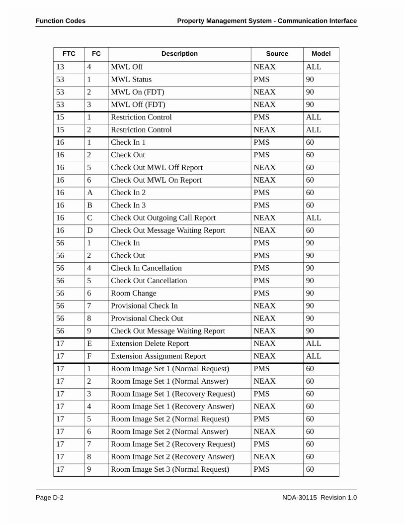
Function Codes Property Management System - Communication Interface
13 4 MWL Off NEAX ALL
53 1 MWL Status PMS 90
53 2 MWL On (FDT) NEAX 90
53 3 MWL Off (FDT) NEAX 90
15 1 Restriction Control PMS ALL
15 2 Restriction Control NEAX ALL
16 1 Check In 1 PMS 60
16 2 Check Out PMS 60
16 5 Check Out MWL Off Report NEAX 60
16 6 Check Out MWL On Report NEAX 60
16 A Check In 2 PMS 60
16 B Check In 3 PMS 60
16 C Check Out Outgoing Call Report NEAX ALL
16 D Check Out Message Waiting Report NEAX 60
56 1 Check In PMS 90
56 2 Check Out PMS 90
56 4 Check In Cancellation PMS 90
56 5 Check Out Cancellation PMS 90
56 6 Room Change PMS 90
56 7 Provisional Check In NEAX 90
56 8 Provisional Check Out NEAX 90
56 9 Check Out Message Waiting Report NEAX 90
17 E Extension Delete Report NEAX ALL
17 F Extension Assignment Report NEAX ALL
17 1 Room Image Set 1 (Normal Request) PMS 60
17 2 Room Image Set 1 (Normal Answer) NEAX 60
17 3 Room Image Set 1 (Recovery Request) PMS 60
17 4 Room Image Set 1 (Recovery Answer) NEAX 60
17 5 Room Image Set 2 (Normal Request) PMS 60
17 6 Room Image Set 2 (Normal Answer) NEAX 60
17 7 Room Image Set 2 (Recovery Request) PMS 60
17 8 Room Image Set 2 (Recovery Answer) NEAX 60
17 9 Room Image Set 3 (Normal Request) PMS 60
FTC FC Description Source Model
Page D-2 NDA-30115 Revision 1.0
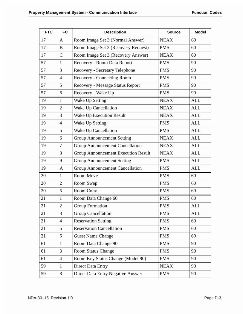
Property Management System - Communication Interface Function Codes
17 A Room Image Set 3 (Normal Answer) NEAX 60
17 B Room Image Set 3 (Recovery Request) PMS 60
17 C Room Image Set 3 (Recovery Answer) NEAX 60
57 1 Recovery - Room Data Report PMS 90
57 3 Recovery - Secretary Telephone PMS 90
57 4 Recovery - Connecting Room PMS 90
57 5 Recovery - Message Status Report PMS 90
57 6 Recovery - Wake Up PMS 90
19 1 Wake Up Setting NEAX ALL
19 2 Wake Up Cancellation NEAX ALL
19 3 Wake Up Execution Result NEAX ALL
19 4 Wake Up Setting PMS ALL
19 5 Wake Up Cancellation PMS ALL
19 6 Group Announcement Setting NEAX ALL
19 7 Group Announcement Cancellation NEAX ALL
19 8 Group Announcement Execution Result NEAX ALL
19 9 Group Announcement Setting PMS ALL
19 A Group Announcement Cancellation PMS ALL
20 1 Room Move PMS 60
20 2 Room Swap PMS 60
20 5 Room Copy PMS 60
21 1 Room Data Change 60 PMS 60
21 2 Group Formation PMS ALL
21 3 Group Cancellation PMS ALL
21 4 Reservation Setting PMS 60
21 5 Reservation Cancellation PMS 60
21 6 Guest Name Change PMS 60
61 1 Room Data Change 90 PMS 90
61 3 Room Status Change PMS 90
61 4 Room Key Status Change (Model 90) PMS 90
59 1 Direct Data Entry NEAX 90
59 8 Direct Data Entry Negative Answer PMS 90
FTC FC Description Source Model
NDA-30115 Revision 1.0 Page D-3
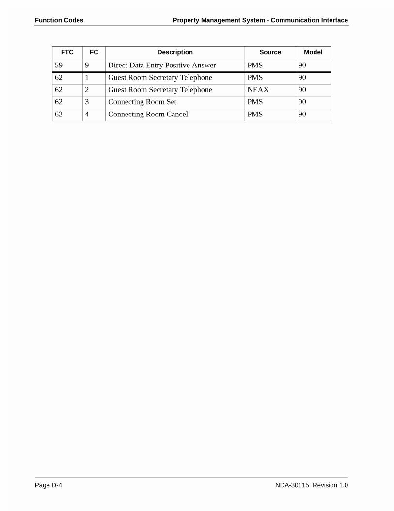
Function Codes Property Management System - Communication Interface
59 9 Direct Data Entry Positive Answer PMS 90
62 1 Guest Room Secretary Telephone PMS 90
62 2 Guest Room Secretary Telephone NEAX 90
62 3 Connecting Room Set PMS 90
62 4 Connecting Room Cancel PMS 90
FTC FC Description Source Model
Page D-4 NDA-30115 Revision 1.0
Recommended