Multifunctional control for gas burning appliances
9.95
5.05
6 0
2
S
ubje
ct t
o ch
ange
with
out
notic
e
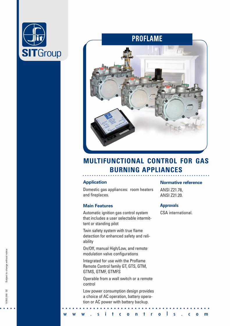
Application
Domestic gas appliances: room heaters and fireplaces. Main Features
Automatic ignition gas control system that includes a user selectable intermit-tent or standing pilot
Twin safety system with true flame detection for enhanced safety and reli-ability
On/Off, manual High/Low, and remote modulation valve configurations
Integrated for use with the Proflame Remote Control family GT, GTS, GTM, GTMS, GTMF, GTMFS
Operable from a wall switch or a remote control
Low power consumption design provides a choice of AC operation, battery opera-tion or AC power with battery backup.
Normative reference
ANSI Z21.78, ANSI Z21.20.
approvals
CSA international.
w w w . s i t c o n t r o l s . c o m
proflaMe
9955056_02(0�2)_��0-�-5_cat.indd1 1 2�/0�/2010 10.�5.��
2
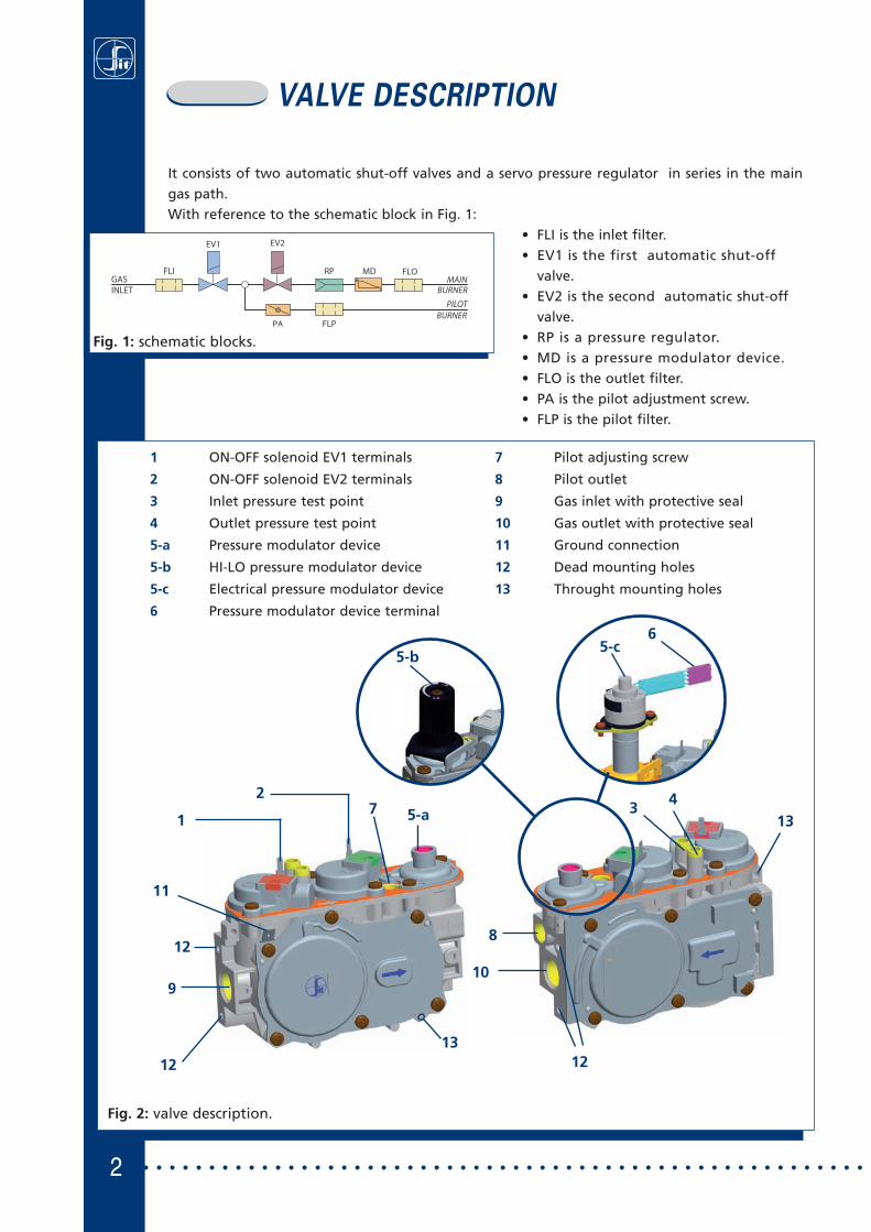
valve DeSCRIPTION
It consists of two automatic shut-off valves and a servo pressure regulator in series in the main gas path. With reference to the schematic block in Fig. 1:
• FLI is the inlet filter. • EV1 is the first automatic shut-off valve. • EV2 is the second automatic shut-off valve. • RP is a pressure regulator. • MD is a pressure modulator device.
• FLO is the outlet filter. • PA is the pilot adjustment screw. • FLP is the pilot filter.
GASINLET
FLI
EV1
RP
EV2
MAINBURNER
PILOTBURNER
FLP
FLO
PA
GASINLET
FLI
EV1
RP
EV2
MAINBURNER
PILOTBURNER
FLP
FLO
PA
MD
Fig. 1: schematic blocks.
1 ON-OFF solenoid EV1 terminals
2 ON-OFF solenoid EV2 terminals
3 Inlet pressure test point
4 Outlet pressure test point
5-a Pressure modulator device
5-b HI-LO pressure modulator device
5-c Electrical pressure modulator device
6 Pressure modulator device terminal
7 Pilot adjusting screw
8 Pilot outlet
9 Gas inlet with protective seal
10 Gas outlet with protective seal
11 Ground connection
12 Dead mounting holes
13 Throught mounting holes
5-b
Fig. 2: valve description.
5-c6
2
11
7
9
5-a
13
12
12
143
8
10
13
12
9955056_02(0�2)_��0-�-5_cat.indd2 2 2�/0�/2010 10.�5.5�

�
valve GeNeRal DaTa
ConstruCtion CharaCteristiCs
• Aluminium alloy body• Inline inlet and outlet• Available bottom inlet and bottom outlet• Pilot outlet• Inlet filter
use speCifiCations
• Installation position Upright, ≤90° from upright ( Never upside down )• Gas families Natural Gas ,LPG• Ambient operating temperature range 32 to 175 °F• Maximum inlet pressure 1/2 psi• NOT for direct burner ignition appliances
MeChaniCal ConneCtions
• Gas inlet and outlet connections - 3/8”- 18 NPT ANSI B 1.20.1 - 5/8”- 18 SAE J512 - 9/16”- 24 UNEF ANSI B 1.1
• Pilot outlet 7/16“- 24 UNS - 2B ANSI
• Pressure test points ø9 mm
• Inlet pressure test point • Outlet pressure test point• Two mounting through holes on the side• Two mounting holes on the gas inlet and outlet
9955056_02(0�2)_��0-�-5_cat.indd� � 2�/0�/2010 10.�5.5�
�
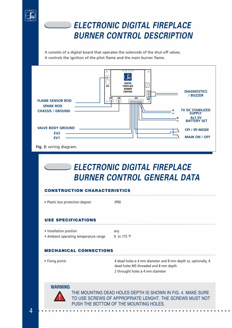
eleCTRONIC DIGITal FIRePlaCe BURNeR CONTROl DeSCRIPTION
It consists of a digital board that operates the solenoids of the shut-off valves.It controls the ignition of the pilot flame and the main burner flame.
eleCTRONIC DIGITal FIRePlaCe BURNeR CONTROl GeNeRal DaTa
ConstruCtion CharaCteristiCs
• Plastic box protection degree: IP00
use speCifiCations
• Installation position any• Ambient operating temperature range 0 to 175 °F
MeChaniCal ConneCtions
• Fixing points 4 dead holes ø 4 mm diameter and 8 mm depth or, optionally, 4 dead holes M5 threaded and 8 mm depth 2 throught holes ø 4 mm diameter
5
5
4
4
3
3
2
2
1
1
D D
C C
B B
A A
CN0
CN4
CN3
DIGITALFIREPLACE
BURNERCONTROL
CN2 CN1
Diagnostics/ BUZZER
4x1.5V BattERY sEt
Main on / oFFEV1EV2
cHassis / gRoUnD
VaLVE BoDY gRoUnD
7V Dc staBiLiZED sUPPLY
sPaRK RoD
FLaME sEnsoR RoD
cPi / iPi MoDE
Fig. 3: wiring diagram.
WARNINGTHE MOUNTING DEAD HOLES DEPTH IS SHOWN IN FIG. �. MAKE SURE TO USE SCREWS OF APPROPRIATE LENGHT. THE SCREWS MUST NOT PUSH THE BOTTOM OF THE MOUNTING HOLES.
9955056_02(0�2)_��0-�-5_cat.indd� � 2�/0�/2010 10.�5.5�
5
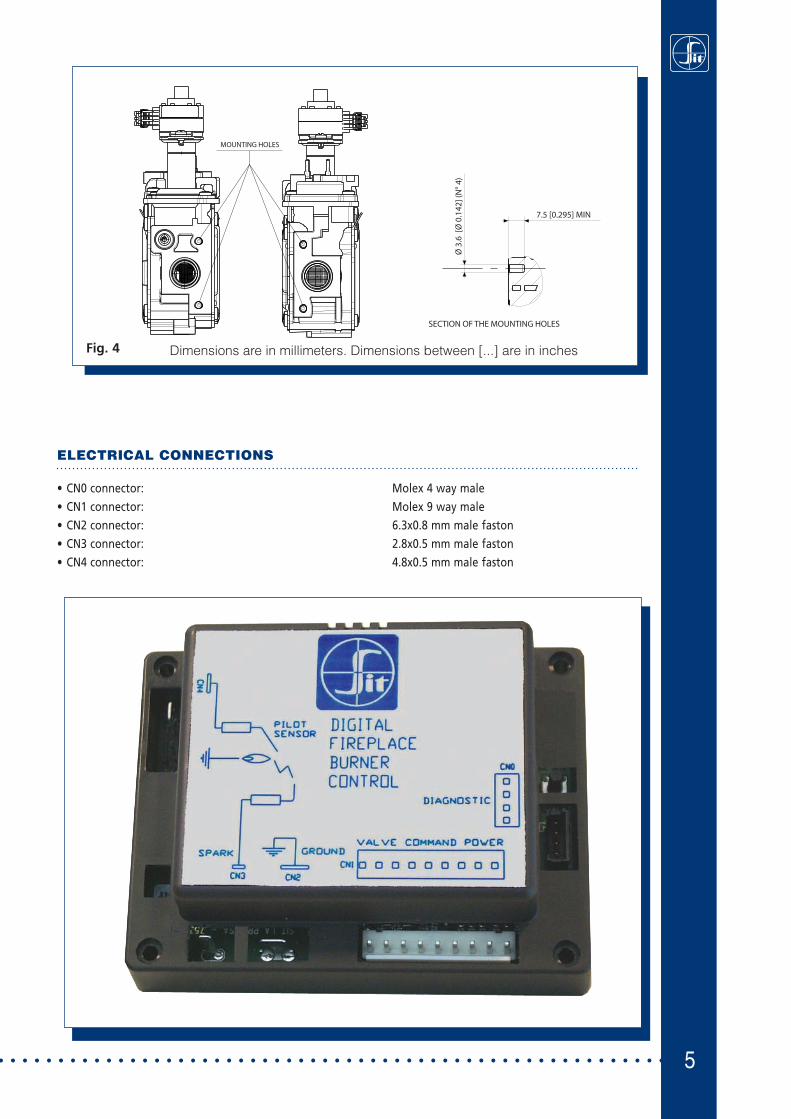
eleCtriCal ConneCtions
• CN0 connector: Molex 4 way male• CN1 connector: Molex 9 way male• CN2 connector: 6.3x0.8 mm male faston• CN3 connector: 2.8x0.5 mm male faston• CN4 connector: 4.8x0.5 mm male faston
Fig. 4
MOUNTING HOLES
SECTION OF THE MOUNTING HOLES
7.5 [0.295] MIN
Ø 3
.6 [
Ø 0
.142
] (N
° 4)
MOUNTING HOLES
SECTION OF THE MOUNTING HOLES
7.5 [0.295] MIN
Ø 3
.6 [
Ø 0
.142
] (N
° 4)
Dimensions are in millimeters. Dimensions between [...] are in inches
9955056_02(0�2)_��0-�-5_cat.indd5 5 2�/0�/2010 10.�5.56
6
valve FUNCTIONal DeSCRIPTION
The Proflame control is equipped with two automatic shut-off valves. It is possible to read the inlet pressure when both valves are de-energized (OFF in Fig. 6).
When the solenoid EV1 is energized the first gas valve opens. The pilot outlet is enabled (PILOT in Fig. 6).
When EV2 is energized the second valve opens and gas flows through the main outlet (OPEN in Fig. 6). It is possible to measure the outlet pressure on the outlet pressure test point.The servo pressure regulator system provides superior performance of outlet pressure regulation. The outlet pressure can be adjusted by a knob (Manual HI-LO version) or by a electrical modulator device.
valve CaPaCITY
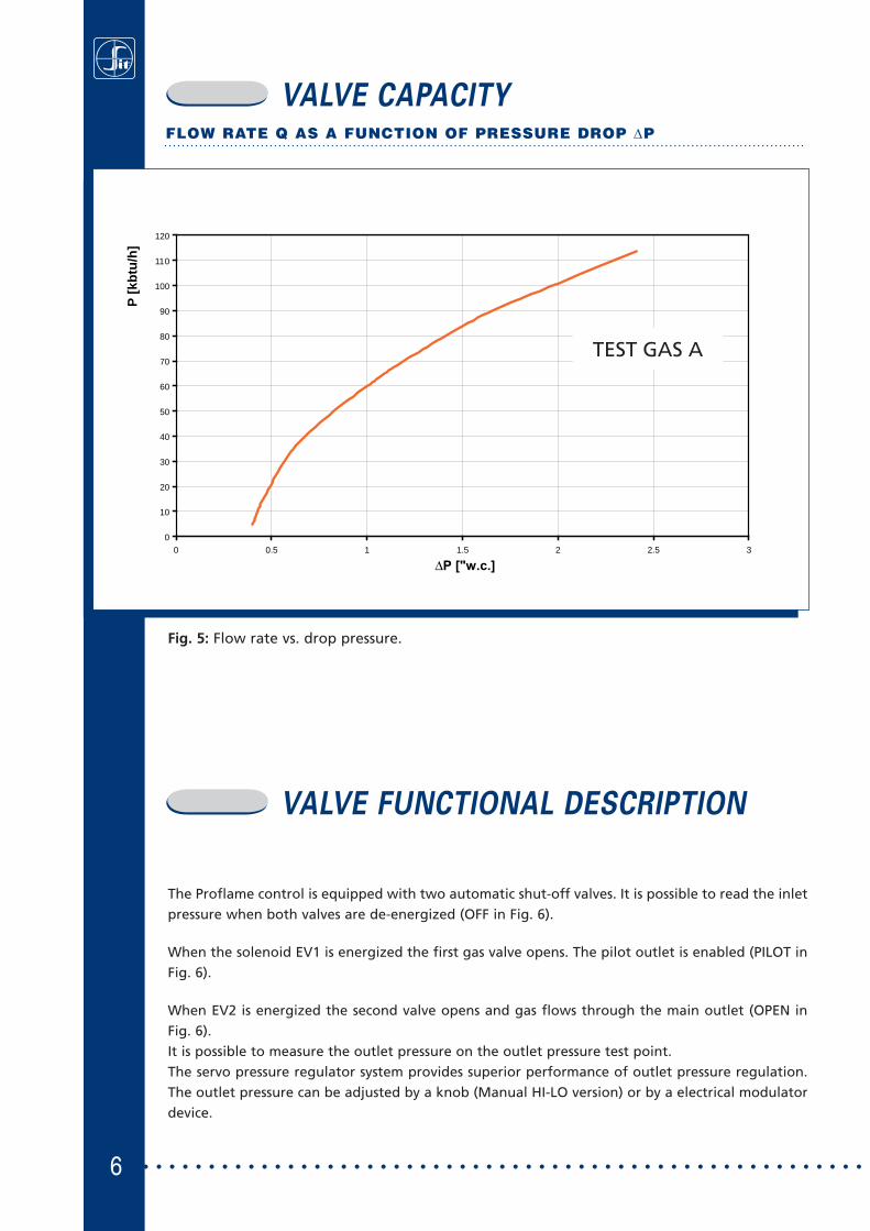
Fig. 5: Flow rate vs. drop pressure.
floW rate Q as a funCtion of pressure Drop ∆p
880- Power test gas A [Kbtu/h, d=0.64, Hi=37.3 Mj/m3]-Pinlet=3,5["w.c.]-d pil = 0.3mm
0
10
20
30
40
50
60
70
80
90
100
110
120
0 0.5 1 1.5 2 2.5 3
P [
kb
tu/h
]
TEST GAS A
9955056_02(0�2)_��0-�-5_cat.indd6 6 2�/0�/2010 10.�5.56
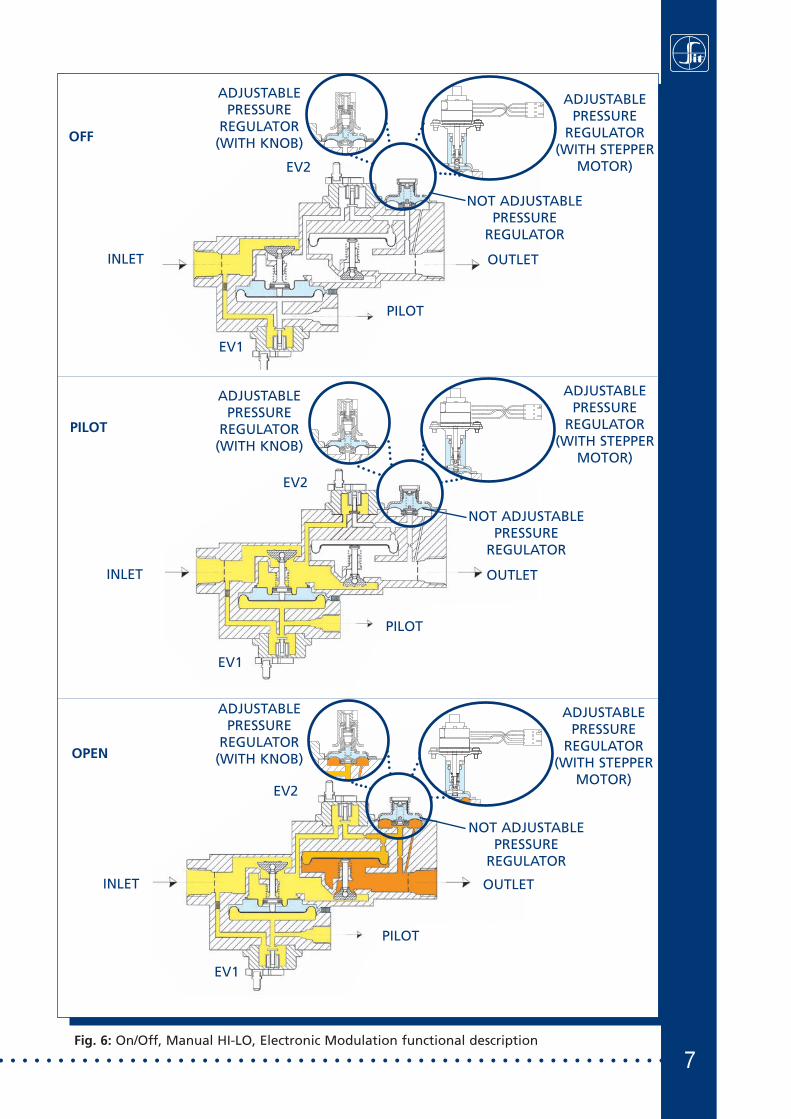
�Fig. 6: On/Off, Manual HI-LO, Electronic Modulation functional description
oFF
PiLot
INLET
EV1
PILOT
EV2
NOT ADJUSTABLE PRESSURE
REGULATOR
OUTLET
INLET
EV1
PILOT
EV2
OUTLET
oPEn
INLET
EV1
PILOT
EV2
OUTLET
NOT ADJUSTABLE PRESSURE
REGULATOR
NOT ADJUSTABLE PRESSURE
REGULATOR
OFF
PILOT
OPEN
OFF
PILOT
OPEN
OFF
PILOT
OPEN
OFF
PILOT
OPEN
ADJUSTABLE PRESSURE
REGULATOR (WITH STEPPER
MOTOR)
ADJUSTABLE PRESSURE
REGULATOR (WITH STEPPER
MOTOR)
ADJUSTABLE PRESSURE
REGULATOR (WITH STEPPER
MOTOR)
ADJUSTABLE PRESSURE
REGULATOR (WITH KNOB)
ADJUSTABLE PRESSURE
REGULATOR (WITH KNOB)
ADJUSTABLE PRESSURE
REGULATOR (WITH KNOB)
OFF
PILOT
OPEN
OFF
PILOT
OPEN
9955056_02(0�2)_��0-�-5_cat.indd� � 2�/0�/2010 10.�6.2�
�
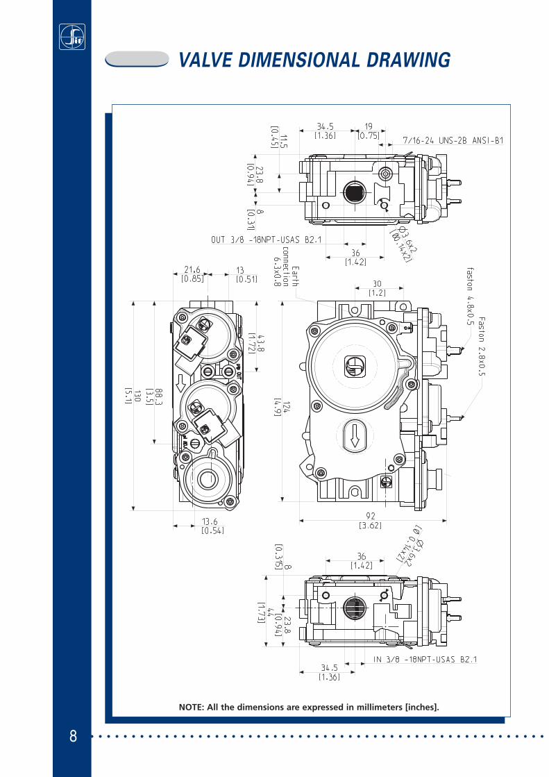
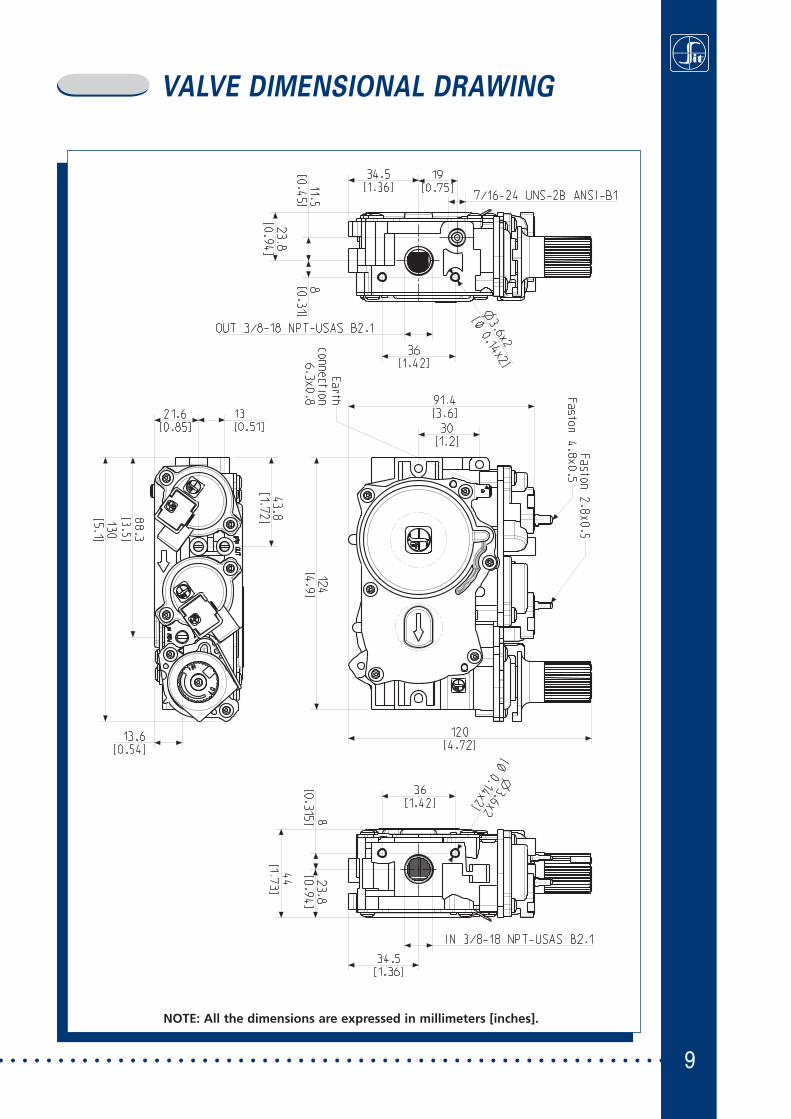
valve DImeNSIONal DRawING
notE: all the dimensions are expressed in millimeters [inches].
9955056_02(0�2)_��0-�-5_cat.indd� � 2�/0�/2010 10.�6.25
9
SOSTITUIR
E CON �
��
valve DImeNSIONal DRawING
notE: all the dimensions are expressed in millimeters [inches].
9955056_02(0�2)_��0-�-5_cat.indd9 9 2�/0�/2010 10.�6.26
10
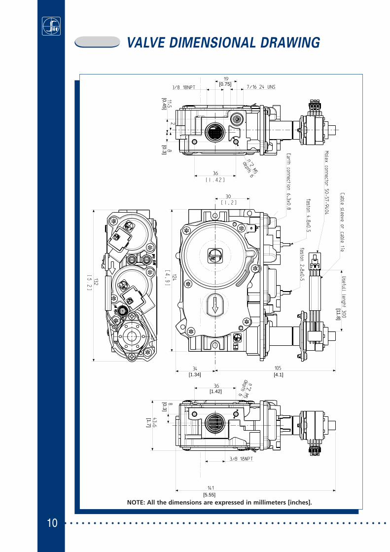
valve DImeNSIONal DRawING
notE: all the dimensions are expressed in millimeters [inches].
[1.7]
[0.3]
[5.55]
[1.34]
[1.42]
[4.1]
[0.75]
[0.45][0.3]
[11.8]
9955056_02(0�2)_��0-�-5_cat.indd10 10 2�/0�/2010 10.�6.26
11
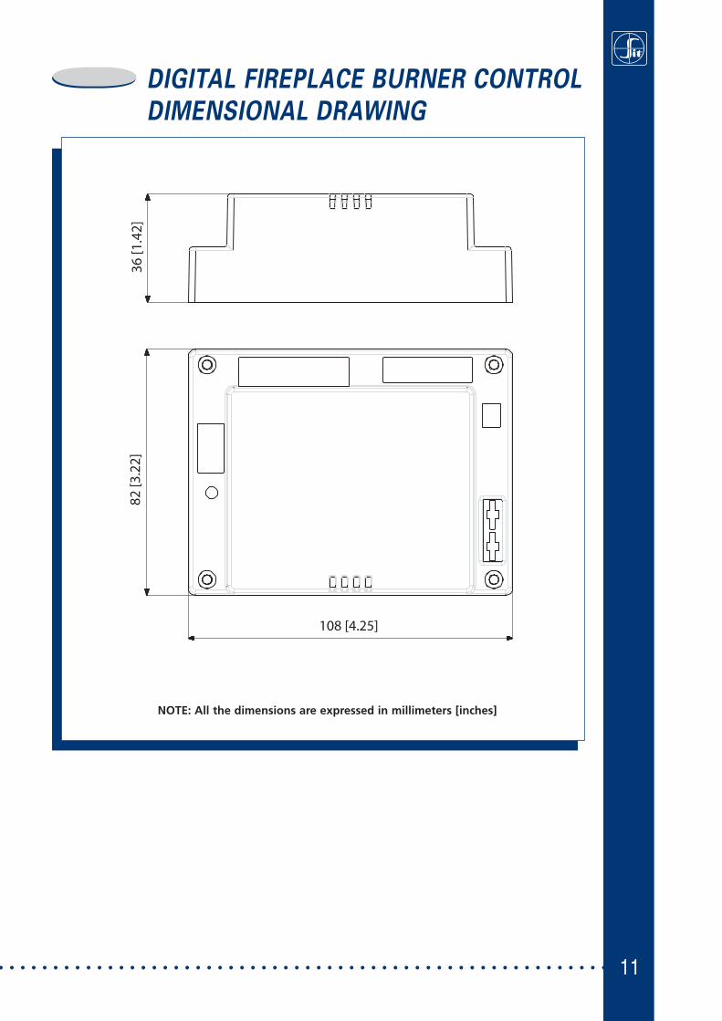
DIGITal FIRePlaCe BURNeR CONTROl DImeNSIONal DRawING
notE: all the dimensions are expressed in millimeters [inches]
82 [3
.22]
36 [1
.42]
108 [4.25]
9955056_02(0�2)_��0-�-5_cat.indd11 11 2�/0�/2010 10.�6.2�

sit controls Usa inc.900 Center Park Drive Suite J
Charlotte, NC 28217 USA
Ph. 704-522-6325, fax 704 522 7945www.sitcontrols.com – e-mail: [email protected]
9955056_02(0�2)_��0-�-5_cat.indd12 12 2�/0�/2010 10.�6.2�
Recommended