
PowerDRIVE-ConnectBZK Hybrid cable for PowerDRIVE-System
Technical information Issued 2017-07
... automates motion.
LENORD+BAUER
Subject to technical modifications and typographical errors.
Internet: www.lenord.comE-Mail: [email protected]
Phone: +49 208 9963–0Fax: +49 208 676292
Lenord, Bauer & Co. GmbHDohlenstraße 3246145 Oberhausen, GermanyD
S22
-BZ
K
General
Pre-assembled hybrid cable for the straightforwardconnection of PowerDRIVE positioning drives
For cabling PowerDRIVE positioning drives with hybridcoupling- M17 or M23 hybrid connector with integrated bus
element for the power supply and buscommunication
- Easy-to-disconnect quick-release coupling For the supply of power to PowerDRIVE positioning
drives with plug connection- M23 mating connector with screw lock
Features
High electromagnetic compatibility(EMC housing screening)
Current carrying capacity according to DIN EN 60512 Length from 3 m to 20 m
Advantages
Reduction of the cabling effort Can be matched to the related connection situation Time-saving during the connection of the PowerDRIVE
positioning drives to the PowerDRIVE-Box Straightforward electrical disconnection of positioning
drives with hybrid connection for maintenance andservice work due to quick-release coupling
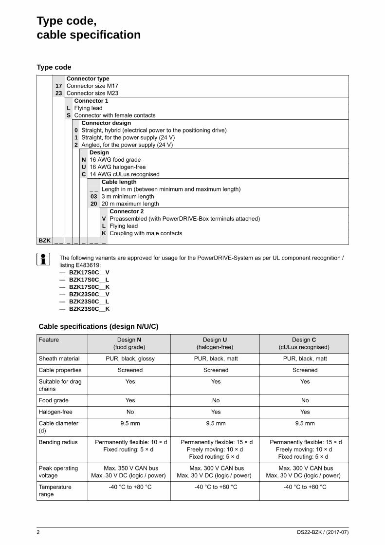
Type code,cable specification
2 DS22-BZK / (2017-07)
Type code
Connector type17 Connector size M1723 Connector size M23
Connector 1L Flying leadS Connector with female contacts
Connector design0 Straight, hybrid (electrical power to the positioning drive)1 Straight, for the power supply (24 V)2 Angled, for the power supply (24 V)
DesignN 16 AWG food gradeU 16 AWG halogen-freeC 14 AWG cULus recognised
Cable length_ _ Length in m (between minimum and maximum length)03 3 m minimum length20 20 m maximum length
Connector 2V Preassembled (with PowerDRIVE-Box terminals attached)L Flying leadK Coupling with male contacts
BZK _ _ _ _ _ _ _ _
The following variants are approved for usage for the PowerDRIVE-System as per UL component recognition /listing E483619:— BZK17S0C__V— BZK17S0C__L— BZK17S0C__K— BZK23S0C__V— BZK23S0C__L— BZK23S0C__K
Cable specifications (design N/U/C)
Feature Design N(food grade)
Design U(halogen-free)
Design C(cULus recognised)
Sheath material PUR, black, glossy PUR, black, matt PUR, black, matt
Cable properties Screened Screened Screened
Suitable for dragchains
Yes Yes Yes
Food grade Yes No No
Halogen-free No Yes Yes
Cable diameter(d)
9.5 mm 9.5 mm 9.5 mm
Bending radius Permanently flexible: 10 × dFixed routing: 5 × d
Permanently flexible: 15 × dFreely moving: 10 × dFixed routing: 5 × d
Permanently flexible: 15 × dFreely moving: 10 × dFixed routing: 5 × d
Peak operatingvoltage
Max. 350 V CAN busMax. 30 V DC (logic / power)
Max. 300 V CAN busMax. 30 V DC (logic / power)
Max. 300 V CAN busMax. 30 V DC (logic / power)
Temperaturerange
-40 °C to +80 °C -40 °C to +80 °C -40 °C to +80 °C
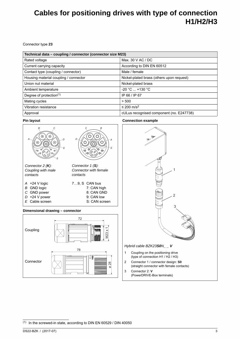
Cables for positioning drives with type of connectionH1/H2/H3
DS22-BZK / (2017-07) 3
Connector type 23
Technical data – coupling / connector (connector size M23)
Rated voltage Max. 30 V AC / DC
Current carrying capacity According to DIN EN 60512
Contact type (coupling / connector) Male / female
Housing material coupling / connector Nickel-plated brass (others upon request)
Union nut material Nickel-plated brass
Ambient temperature -20 °C ... +130 °C
Degree of protection(1) IP 66 / IP 67
Mating cycles > 500
Vibration resistance ≤ 200 m/s2
Approval cULus recognised component (no. E247738)
Pin layout
A
B C
D
E5 1
6 3
4 28
79 10
S
Connector 2 (K):Coupling with malecontacts
A
BC
D
E51
63
42 87910
Connector 1 (S):Connector with femalecontacts
ABCDE
+24 V logicGND logicGND power+24 V powerCable screen
7…9, S CAN bus7: CAN high8: CAN GND9: CAN lowS: CAN screen
Dimensional drawing – connector
Coupling
72
M23
x 1
Connector
78
ø 28
Connection example
1
2
3
Hybrid cable BZK23S0N_ _ V
1 Coupling on the positioning drive(type of connection H1 / H2 / H3)
2 Connector 1 / connector design: S0(straight connector with female contacts)
3 Connector 2: V(PowerDRIVE-Box terminals)
(1) In the screwed-in state, according to DIN EN 60529 / DIN 40050

Cables for positioning drives with type of connectionH1/H2/H3
4 DS22-BZK / (2017-07)
Cable variants for positioning drives with type of connection H1 / H2 / H3
H1: 30 cmH2: 50 cmH3: 100 cm
M23
PowerDRIVE-Box
BZK23S0NxxKBZK23S0UxxKBZK23S0CxxK
BZK23S0NxxVBZK23S0UxxV
BZK23S0NxxLBZK23S0UxxLBZK23S0CxxL
BZK23S0NxxKBZK23S0UxxKBZK23S0CxxK
optional
BZK23S0CxxVPowerDRIVE-Box
xx = length in m
Design N / U:Spring-cage terminals for the PowerDRIVE-Boxwith design N / U
Design C:Spring-cage terminals for the PowerDRIVE-Boxwith design C
Pin layout for connector 2 “V” (pre-assembled) and “L” (flying lead)
Flying lead(connector 2: L)
Pre-assembled,connection to the PowerDRIVE-Box
(connector 2: V)
Signal identifier
Corecolour/core no.
Cross-sectiondesign: N/U
Cross-sectiondesign: C
4-pole spring-cageterminal (internalpositioning drivecommunication)pin identifier
4-pole spring-cage terminal(positioning drive powersupply)pin identifier
red/1 0.5 mm2 0.5 mm2 – 3 +24 V logic
red/2 1.5 mm2 2.5 mm2 – 1 +24 V power
black/2 1.5 mm2 2.5 mm2 – 2 GND power
black/1 0.5 mm2 0.5 mm2 – 4 GND logic
black 0.14 mm2 0.14 mm2 1 – CAN GND
green 0.25 mm2 0.25 mm2 3 – CAN low
yellow 0.25 mm2 0.25 mm2 2 – CAN high
Cable screen – – –
CAN screen – – –
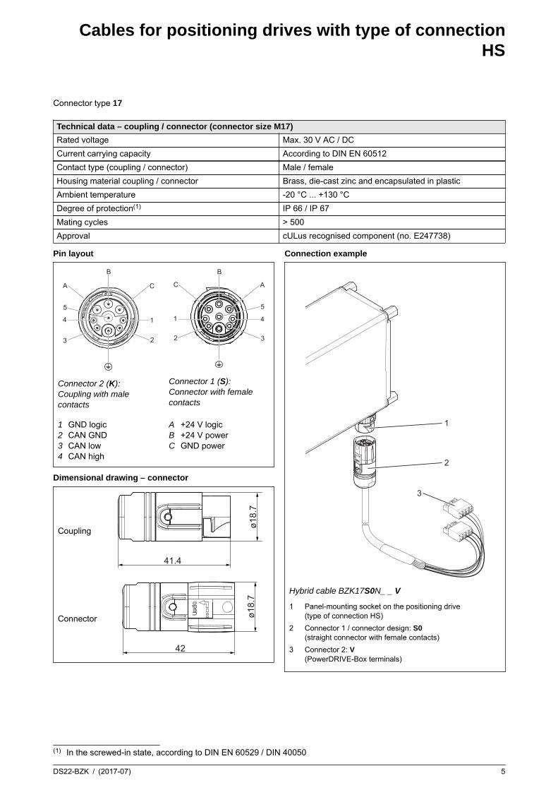
Cables for positioning drives with type of connectionHS
DS22-BZK / (2017-07) 5
Connector type 17
Technical data – coupling / connector (connector size M17)
Rated voltage Max. 30 V AC / DC
Current carrying capacity According to DIN EN 60512
Contact type (coupling / connector) Male / female
Housing material coupling / connector Brass, die-cast zinc and encapsulated in plastic
Ambient temperature -20 °C ... +130 °C
Degree of protection(1) IP 66 / IP 67
Mating cycles > 500
Approval cULus recognised component (no. E247738)
Pin layout
C
1
2
A
4
3
B
5
Connector 2 (K):Coupling with malecontacts
A
4
3
C
1
2
B
5
Connector 1 (S):Connector with femalecontacts
1234
GND logicCAN GNDCAN lowCAN high
ABC
+24 V logic+24 V powerGND power
Dimensional drawing – connector
Coupling
41.4
ø18.
7
Connector
42
ø18.
7Connection example
1
2
3
Hybrid cable BZK17S0N_ _ V
1 Panel-mounting socket on the positioning drive(type of connection HS)
2 Connector 1 / connector design: S0(straight connector with female contacts)
3 Connector 2: V(PowerDRIVE-Box terminals)
(1) In the screwed-in state, according to DIN EN 60529 / DIN 40050

Cables for positioning drives with type of connectionHS
6 DS22-BZK / (2017-07)
Cable variants for positioning drives with type of connection HS
PowerDRIVE-Box
HS
M17
BZK17S0NxxKBZK17S0UxxKBZK17S0CxxK
BZK17S0NxxVBZK17S0UxxV
BZK17S0NxxLBZK17S0UxxLBZK17S0CxxL
BZK17S0NxxKBZK17S0UxxKBZK17S0CxxK
optional
PowerDRIVE-Box
BZK17S0CxxV
xx = length in m
Design N / U:Spring-cage terminals for the PowerDRIVE-Boxwith design N / U
Design C:Spring-cage terminals for the PowerDRIVE-Boxwith design C
Pin layout for connector 2 “V” (pre-assembled) and “L” (flying lead)
Flying lead(connector 2: L)
Pre-assembled,connection to the PowerDRIVE-Box
(connector 2: V)
Signal identifier
Corecolour/core no.
Cross-sectiondesign: N/U
Cross-sectiondesign: C
4-pole spring-cageterminal (internalpositioning drivecommunication)pin identifier
4-pole spring-cage terminal(positioning drive powersupply)pin identifier
red/1 0.5 mm2 0.5 mm2 – 3 +24 V logic
red/2 1.5 mm2 2.5 mm2 – 1 +24 V power
black/2 1.5 mm2 2.5 mm2 – 2 GND power
black/1 0.5 mm2 0.5 mm2 – 4 GND logic
black 0.14 mm2 0.14 mm2 1 – CAN GND
green 0.25 mm2 0.25 mm2 3 – CAN low
yellow 0.25 mm2 0.25 mm2 2 – CAN high
Cable screen – – –
CAN screen – – –
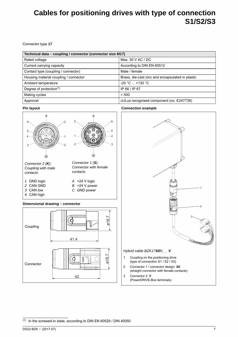
Cables for positioning drives with type of connectionS1/S2/S3
DS22-BZK / (2017-07) 7
Connector type 17
Technical data – coupling / connector (connector size M17)
Rated voltage Max. 30 V AC / DC
Current carrying capacity According to DIN EN 60512
Contact type (coupling / connector) Male / female
Housing material coupling / connector Brass, die-cast zinc and encapsulated in plastic
Ambient temperature -20 °C ... +130 °C
Degree of protection(1) IP 66 / IP 67
Mating cycles > 500
Approval cULus recognised component (no. E247738)
Pin layout
C
1
2
A
4
3
B
5
Connector 2 (K):Coupling with malecontacts
A
4
3
C
1
2
B
5
Connector 1 (S):Connector with femalecontacts
1234
GND logicCAN GNDCAN lowCAN high
ABC
+24 V logic+24 V powerGND power
Dimensional drawing – connector
Coupling
41.4
ø18.
7
Connector
42
ø18.
7Connection example
1
2
3
Hybrid cable BZK17S0N_ _ V
1 Coupling on the positioning drive(type of connection S1 / S2 / S3)
2 Connector 1 / connector design: S0(straight connector with female contacts)
3 Connector 2: V(PowerDRIVE-Box terminals)
(1) In the screwed-in state, according to DIN EN 60529 / DIN 40050

Cables for positioning drives with type of connectionS1/S2/S3
8 DS22-BZK / (2017-07)
Cable variants for positioning drives with type of connection S1 / S2 / S3
S1: 30 cmS2: 50 cmS3: 100 cm
M17
PowerDRIVE-Box
BZK17S0NxxKBZK17S0UxxKBZK17S0CxxK
BZK17S0NxxVBZK17S0UxxV
BZK17S0NxxLBZK17S0UxxLBZK17S0CxxL
BZK17S0NxxKBZK17S0UxxKBZK17S0CxxK
optional
PowerDRIVE-Box
BZK17S0CxxV
xx = length in m
Design N / U:Spring-cage terminals for the PowerDRIVE-Boxwith design N / U
Design C:Spring-cage terminals for the PowerDRIVE-Boxwith design C
Pin layout for connector 2 “V” (pre-assembled) and “L” (flying lead)
Flying lead(connector 2: L)
Pre-assembled,connection to the PowerDRIVE-Box
(connector 2: V)
Signal identifier
Corecolour/core no.
Cross-sectiondesign: N/U
Cross-sectiondesign: C
4-pole spring-cageterminal (internalpositioning drivecommunication)pin identifier
4-pole spring-cage terminal(positioning drive powersupply)pin identifier
red/1 0.5 mm2 0.5 mm2 – 3 +24 V logic
red/2 1.5 mm2 2.5 mm2 – 1 +24 V power
black/2 1.5 mm2 2.5 mm2 – 2 GND power
black/1 0.5 mm2 0.5 mm2 – 4 GND logic
black 0.14 mm2 0.14 mm2 1 – CAN GND
green 0.25 mm2 0.25 mm2 3 – CAN low
yellow 0.25 mm2 0.25 mm2 2 – CAN high
Cable screen – – –
CAN screen – – –
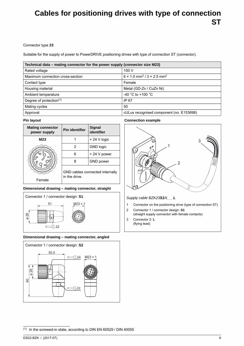
Cables for positioning drives with type of connectionST
DS22-BZK / (2017-07) 9
Connector type 23 Suitable for the supply of power to PowerDRIVE positioning drives with type of connection ST (connector).
Technical data – mating connector for the power supply (connector size M23)
Rated voltage 150 V
Maximum connection cross-section 6 × 1.0 mm2 / 3 × 2.5 mm2
Contact type Female
Housing material Metal (GD-Zn / CuZn Ni)
Ambient temperature -40 °C to +100 °C
Degree of protection(1) IP 67
Mating cycles 50
Approval cULus recognised component (no. E153698)
Pin layout
Mating connectorpower supply
Pin identifierSignalidentifier
M23
567
81
2
34
9
Female
1 + 24 V logic
2 GND logic
6 + 24 V power
8 GND power
GND cables connected internallyin the drive.
Dimensional drawing – mating connector, straight
Connector 1 / connector design: S1
56
7
81
2
34
9
ø 26
51 M23 × 1
22
Dimensional drawing – mating connector, angled
Connector 1 / connector design: S2
5
6
781
2
34
9
M23 × 150.5
60ø
26
24
22
Connection example
1
2
3
Supply cable BZK23S1N_ _ L
1 Connector on the positioning drive (type of connection ST)
2 Connector 1 / connector design: S1(straight supply connector with female contacts)
3 Connector 2: L(flying lead)
(1) In the screwed-in state, according to DIN EN 60529 / DIN 40050
Cables for positioning drives with type of connectionST
10 DS22-BZK / (2017-07)
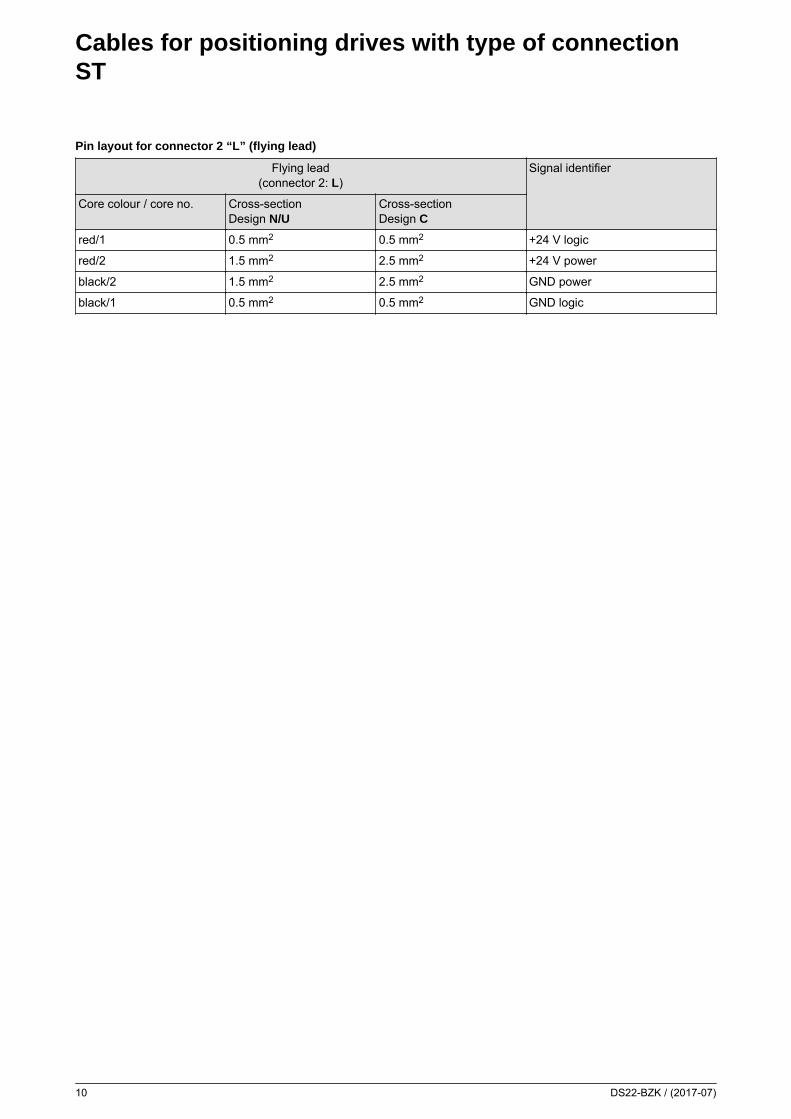
Pin layout for connector 2 “L” (flying lead)
Flying lead(connector 2: L)
Signal identifier
Core colour / core no. Cross-sectionDesign N/U
Cross-sectionDesign C
red/1 0.5 mm2 0.5 mm2 +24 V logic
red/2 1.5 mm2 2.5 mm2 +24 V power
black/2 1.5 mm2 2.5 mm2 GND power
black/1 0.5 mm2 0.5 mm2 GND logic

Your notes:
DS22-BZK / (2017-07) 11

12 DS22-BZK / (2017-07)
Lenord, Bauer & Co. GmbHDohlenstraße 3246145 Oberhausen, GermanyPhone:Fax:
+49 208 9963–0+49 208 676292
Internet: www.lenord.comE-Mail: [email protected]
Subject to technical modifications and typographical errors.
Recommended


![PowerDrive Archer - Oilfield Services | Schlumberger · · 2013-06-05+5.667e+04 +4.750e+04 +3.833e+04 +2.917e+04 +2.000e+04 ... psi [kPa] 600 to 750 [4,137 to 5,171] ... PowerDrive](https://img.dokumen.tips/doc/110x75/5adcb1887f8b9aa5088bd029/powerdrive-archer-oilfield-services-schlumberger-5667e04-4750e04-3833e04.jpg)


