1
Geometrical optics
Chapter 24
Ancient times & Middle Ages: light consist of stream of particles corpuscles
19th century: light is a wave (EM wave)
20th century: several effects associated with the emission and absorption of light revel that it also has a particle aspectand that the energy carried by light waves is packaged in discrete bundles called photons.
Quantum electrodynamics – a comprehensive theory that includes both wave and particle properties.
The propagation of light is best described by a wave model
The emission and absorption by atoms and nuclei requires a particle approach
Nature of Light
Wave Front – a convenient concept to describe wave propagation
A wave front is the locus of all adjacent points at which the phase of vibration of the wave is the same
Wave Fronts
It is very convenient to represent a light wave by rays rather than by wave fronts
A ray is an imaginary line along the direction of travel of the wave
Rays
spherical and planar wave fronts and rays
The branch of optics for which the ray description is adequate is called geometric optics
The branch dealing specifically with wave behavior is called physical optics
The reflection of light
Part 1
Reflection and Refraction
When a light ray travels from one medium to another, part of the incident light is reflected and part of the light is transmitted at the boundary between the two media.
The transmitted part is said to be refracted in the second medium.
incident ray reflected ray
refracted ray

2
Types of Reflection
If the surface from which the light is reflected is smooth, then the light undergoes specular reflection (parallel rays will all be reflected in the same directions).
If, on the other hand, the surface is rough, then the light will undergo diffuse reflection(parallel rays will be reflected in a variety of directions)
Eduard Manet – A Bar at the Foleis-Bergère (1882)
A real image is one in which light actually passes through the image pointReal images can be displayed on screensA virtual image is one in which the light does not pass through the image pointThe light appears to diverge from that pointVirtual images cannot be displayed on screens
Types of Images for Mirrors and Lenses The Law of Reflection
For specular reflection the incident angle θi equals the reflected angle θr:
The angles are measured relative to the normal as shown.
ri θθ =
Plane Mirrors
A mirror is a surface that can reflect a beam of light in one direction instead of either scattering it widely in many directions or absorbing it.
Forming Images with a Plane Mirror
A plane mirror is simply a flat mirror.
Consider an object placed at point P in front of a plane mirror. An image will be formed at point P´ behind the mirror.
do diFor a plane mirror:
do = di and ho = hi
ho hi
do = distance from object to mirror
di = distance from image to mirror
ho = height of objecthi = height of image

3
Plane Mirrors
A plane mirror image has the following properties:
The image distance equals the object distance
The image is unmagnified
The image is virtual
The image is not inverted
What is wrong with the painting?
Conceptual Checkpoint
To save expenses, you would like to buy the shortest mirror that will allow you to see your entire body. Should the mirror be equal to your height?Does the answer depend on how far away from the mirror you stand? Spherical Mirrors
Part 2
Spherical Mirrors
A spherical mirror is a mirror whose surface shape is spherical with radius of curvature R. There are two types of spherical mirrors: concave and convex.We will orient the mirrors so that the reflecting surface is on the left side of the mirror. The objectwill be to left of the mirror itself.
concave
convex
Concave Mirror, Notation
• The mirror has a radius of curvature of R
• Its center of curvature is the point C
• Point V is the center of the spherical segment
• A line drawn from C to V is called the principle axis of the mirror
4
Focal Point
When parallel rays are incident upon a spherical mirror, the reflected rays intersect at the focal point F.
For a concave mirror, the focal point is in front of the mirror.
For a convex mirror, the focal point is behind the mirror. The incident rays
diverge from the convex mirror, but they trace back to the focal point F.
Focal Length Shown by Parallel Rays
Focal Length
The focal length f is the distance from the surface of the mirror to the focal point. It can be shown that the focal length is half the radius of curvature of the mirror.
Sign Convention: the focal length is negative if the focal point is behind the mirror.
For a concave mirror, f = ½R
For a convex mirror, f = −½R (R is always positive)
Ray Tracing
We will use three principal rays to determine where an image will be located.
The parallel ray (P ray) reflects through the focal point. The focal ray (F ray) reflects parallel to the axis, and the center-of-curvature ray (C ray) reflects back along its incoming path.
Ray Tracing – Examples
concave convex
Virtual imageReal image
Real images form on the side of the mirror where the object is, and virtual images form on the opposite side
More examples: Images from spherical mirrors
5
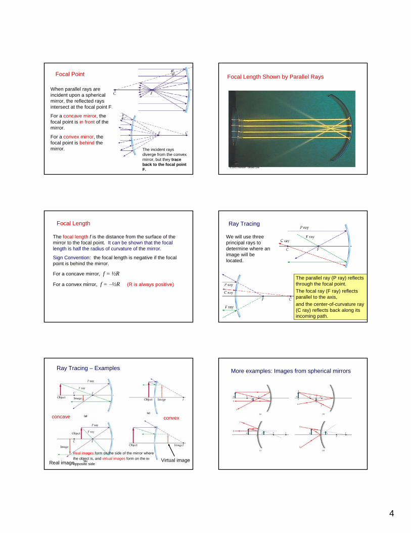
Ray Diagram for Concave Mirror, p > R
• The image is real• The image is inverted• The image is smaller than the object
Ray Diagram for a Concave Mirror, p < f
• The image is virtual• The image is upright• The image is larger than the object
Ray Diagram for a Convex Mirror
• The image is virtual• The image is upright• The image is smaller than the object
Spherical Aberration
• Mirror is not exactly spherical
• This results in a blurred image
• This effect is called spherical aberration
Image Formed by a Concave Mirror
• Geometry shows the relationship between the image and object distances
This is called the mirror equation
1 1 2p q R+ =

6
The Mirror Equation
The ray tracing technique shows qualitatively where the image will be located. The distance from the mirror to the image, di, can be found from the mirror equation:
fdd io
111=+
do = distance from object to mirror
di = distance from image to mirror
f = focal length
Sign Conventions:di is positive if the image is in
front of the mirror (real image)di is negative if the image is
behind the mirror (virtual image)
f is positive for concave mirrorsf is negative for convex mirrorsm is positive for upright imagesm is negative for inverted images
o
i
o
idd
hh
m −===heightobject height image
image magnification. If m is negative, the image is inverted (upside down).
Example 1
An object is placed 30 cm in front of a concave mirror of radius 10 cm. Where is the image located? Is it real or virtual? Is it upright or inverted? What is the magnification of the image?
0
1 1 1 1 1 110302
1 1 1 5 30 6 cm5 30 30 5
i i
ii
d d f d
or dd
+ = + =⎛ ⎞+⎜ ⎟⎝ ⎠×
= − = =−
0
6 0.230
Image is smaller, real and inverted.
idm
d= − = − = −
problem
Example 2
An object is placed 3 cm in front of a concave mirror of radius 20 cm. Where is the image located? Is it real or virtual? Is it upright or inverted? What is the magnification of the image?
0
1 1 1 1 1 12032
1 1 1 3 10 4.3 cm10 3 7
i i
ii
d d f d
or dd
+ = + =⎛ ⎞⎜ ⎟⎝ ⎠×
= − = − = −
0
4.3 1.433
Image is larger, virtual, and upright.
idm
d= − = =
problemExample 3
An object is placed 5 cm in front of a convex mirror of focal length 10 cm. Where is the image located? Is it real or virtual? Is it upright or inverted? What is the magnification of the image?
0
1 1 1 1 1 15 10
1 1 110 55 10 3.33 cm
15
i i
i
i
d d f d
ord
d
+ = + = −
= − −
×= − = −
0
3.33 0.675
Image is smaller, virtual, and upright.
idm
d= − = =
problem
Problem
A concave mirror produces a virtual image that is three times as tall as the object. (a) If the object is 22 cm in front of the mirror, what is the image distance? (b) What is the focal length of this mirror?
0
.)
3 66 cm22
i
ii
da m
dd
d
= −
= − = −0
1 1 1 1 1 1.)22 66
66 22 33 cm66 22
i
bd d f f
f
+ = − =
×= =
−
problem
The Refraction of Light
Part 3
7
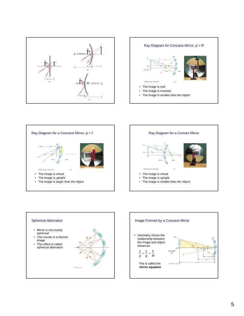
The Refraction of Light
The speed of light is different in different materials. We define the index of refraction, n, of a material to be the ratio of the speed of light in vacuum to the speed of light in the material:
When light travels from one medium to another its velocity and wavelength change, but its frequency remains constant. For a vacuum, n = 1For other media, n > 1n is a unitless ratio
vcn =
Snell’s LawIn general, when light enters a new material its direction will change. The angle of refraction θ2 is related to the angle of incidence θ1 by Snell’s Law:
where v is the velocity of light in the medium.
Snell’s Law can also be written as θ1
θ2
Air
GlassThe angles θ1 and θ2 are measured relative to the line normal to the surface between the two materials.
Normal line
2211 sinsin θθ nn =
2
2
1
1 sinsinvvθθ
=
n = 1.2n = 1.6
Example: Which way will the rays bend?
Which of these rays can be the refracted ray?
n = 1.4 n = 2
2211 sinsin θθ nn =
Application – Day and Night Settings on Auto Mirrors
• With the daytime setting, the bright beam of reflected light is directed into the driver’s eyes
• With the nighttime setting, the dim beam of reflected light is directed into the driver’s eyes, while the bright beam goes elsewhere
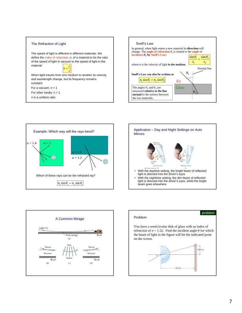
A Common Mirage Problem
You have a semicircular disk of glass with an index of refraction of n = 1.52. Find the incident angle θ for which the beam of light in the figure will hit the indicated point on the screen.
problem
8
1 1 2 2
1 2 2
2
1
1
sin sin51 sin 1.52 sin tan20
Therefore 14
sin 1.52 sin14
Therefore 21.6
n nθ θ
θ θ θ
θ
θ
θ
=
× = × =
=
= ×
=
o
o
o
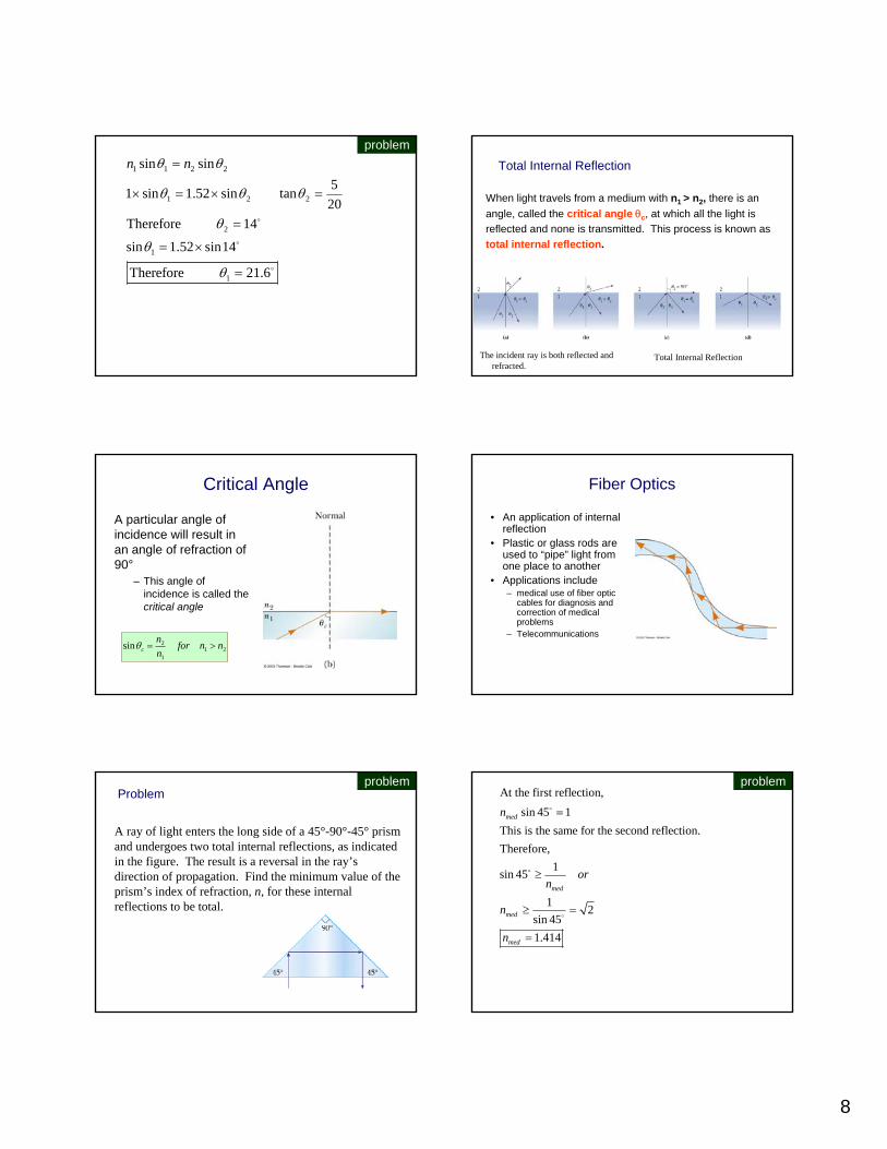
problemTotal Internal Reflection
When light travels from a medium with n1 > n2, there is an angle, called the critical angle θc, at which all the light is reflected and none is transmitted. This process is known as total internal reflection.
The incident ray is both reflected and refracted.
Total Internal Reflection
Critical Angle
A particular angle of incidence will result in an angle of refraction of 90°
– This angle of incidence is called the critical angle
211
2sin nnfornn
c >=θ
Fiber Optics
• An application of internal reflection
• Plastic or glass rods are used to “pipe” light from one place to another
• Applications include– medical use of fiber optic
cables for diagnosis and correction of medical problems
– Telecommunications
Problem
A ray of light enters the long side of a 45°-90°-45° prism and undergoes two total internal reflections, as indicated in the figure. The result is a reversal in the ray’s direction of propagation. Find the minimum value of the prism’s index of refraction, n, for these internal reflections to be total.
problemAt the first reflection,
sin 45 1This is the same for the second reflection.Therefore,
1sin 45
1 2sin 451.414
med
med
med
med
n
orn
n
n
=
≥
≥ =
=
o
o
o
problem

9
Question
Sometimes when looking at a window, one sees two reflected images, slightly displaced from each other.What causes this effect?
?Question
A student claims that, because of atmospheric refraction, the sun can be seen after it has set and that the day is therefore longer than it would be if the earth had no atmosphere.
What does the student mean by saying the sun can be seen after it has set?
Does the same effect also occur at sunrise?
?
Lenses
Part 4Lenses
Light is reflected from a mirror. Light is refracted through a lens.
Focal Point
The focal point of a lens is the place where parallel rays incident upon the lens converge.
converging lens diverging lens
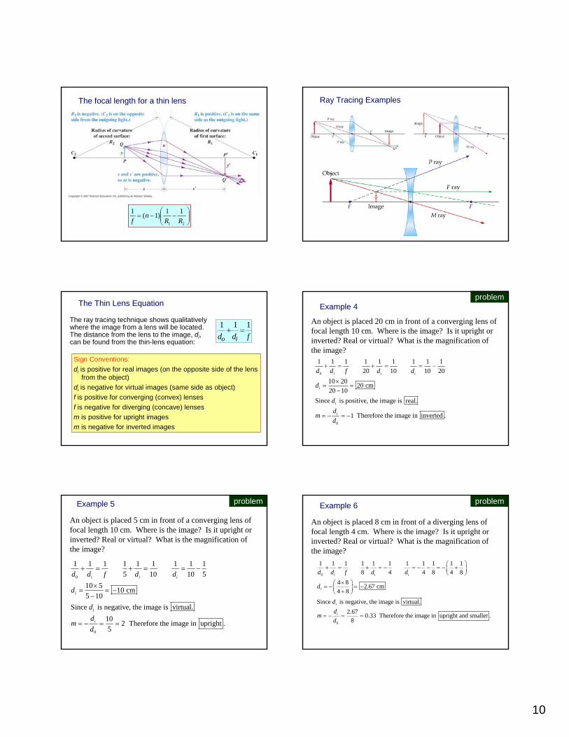
Ray Tracing for Lenses
The P ray propagates parallel to the principal axis until it encounters the lens, where it is refracted to pass through the focal point on the far side of the lens. The F ray passes through the focal point on the near side of the lens, then leaves the lens parallel to the principal axis. The M ray passes through the middle of the lens with no deflection.
Just as for mirrors we use three “easy” rays to find the image from a lens. The lens is assumed to be thin.
10
The focal length for a thin lens
⎟⎟⎠
⎞⎜⎜⎝
⎛−−=
21
11)1(1RR
nf
Ray Tracing Examples
The Thin Lens Equation
The ray tracing technique shows qualitatively where the image from a lens will be located. The distance from the lens to the image, di, can be found from the thin-lens equation:
fdd io
111=+
Sign Conventions:di is positive for real images (on the opposite side of the lens
from the object)di is negative for virtual images (same side as object)f is positive for converging (convex) lensesf is negative for diverging (concave) lensesm is positive for upright imagesm is negative for inverted images
Example 4
An object is placed 20 cm in front of a converging lens of focal length 10 cm. Where is the image? Is it upright or inverted? Real or virtual? What is the magnification of the image?
0
0
1 1 1 1 1 1 1 1 120 10 10 20
10 20 20 cm20 10
Since is positive, the image is real.
1 Therefore the image in inverted .
i i i
i
i
i
d d f d d
d
dd
md
+ = + = = −
×= =
−
= − = −
problem
Example 5
An object is placed 5 cm in front of a converging lens of focal length 10 cm. Where is the image? Is it upright or inverted? Real or virtual? What is the magnification of the image?
0
0
1 1 1 1 1 1 1 1 15 10 10 5
10 5 10 cm5 10
Since is negative, the image is virtual.10 2 Therefore the image in upright .5
i i i
i
i
i
d d f d d
d
dd
md
+ = + = = −
×= = −
−
= − = =
problem Example 6
An object is placed 8 cm in front of a diverging lens of focal length 4 cm. Where is the image? Is it upright or inverted? Real or virtual? What is the magnification of the image?
0
0
1 1 1 1 1 1 1 1 1 1 18 4 4 8 4 8
4 8 2.67 cm4 8
Since is negative, the image is virtual.2.67 0.33 Therefore the image in upright and smaller .
8
i i i
i
i
i
d d f d d
d
dd
md
⎛ ⎞+ = + = − = − − = − +⎜ ⎟⎝ ⎠
×⎛ ⎞= − = −⎜ ⎟+⎝ ⎠
= − = =
problem

11
Problem
(a) Determine the distance from lens 1 to the final image for the system shown in the figure. (b) What is the magnification of this image?
When you have two lenses, the image of the first lens is the object for the second lens.
problem
( )
0
0
1 1 1 1 1 1 1 1 1 1 1First lens 24 7 7 24 7 24
7 24 5.42 cm7 24
1 1 1 1 1 1 1 1 1Second lens 35 5.42 14 14 40.42
14 40.42 21.42 cm40.42 14
Distance from lens 1 is 21.4
i i i
i
i i i
i
d d f d d
d
d d f d d
d
⎛ ⎞+ = + = − = − − = − +⎜ ⎟⎝ ⎠
×⎛ ⎞= − = −⎜ ⎟+⎝ ⎠
+ = + = = −+
×⎛ ⎞= =⎜ ⎟−⎝ ⎠
1 20 01 2
2 35 56.42 cm
5.42 21.42 0.12 24 40.42
i id dm m m
d d
+ =
⎛ ⎞ ⎛ ⎞ ⎛ ⎞ ⎛ ⎞= × = − × − = × − = −⎜ ⎟ ⎜ ⎟ ⎜ ⎟ ⎜ ⎟⎝ ⎠ ⎝ ⎠⎝ ⎠ ⎝ ⎠
problem
Dispersion
Part 5
Dispersion
In a material, the velocity of light (and therefore the index of refraction) can depend on the wavelength. This is known as dispersion. Blue light travels slower in glass and water than does red light.
As a result of dispersion, different colors entering a material will be refracted into different angles.
Dispersive materials can be used to separate a light beam into its spectrum (the colors that make up the light beam). Example: prism
The Rainbow Observing the Rainbow
• If a raindrop high in the sky is observed, the red ray is seen
• A drop lower in the sky would direct violet light to the observer
• The other colors of the spectra lie in between the red and the violet
12
Using Spectra to Identify Gases
All hot, low pressure gases emit their own characteristic spectraThe particular wavelengths emitted by a gas serve as “fingerprints” of that gas
Some uses of spectral analysisIdentification of moleculesIdentification of elements in distant starsIdentification of minerals
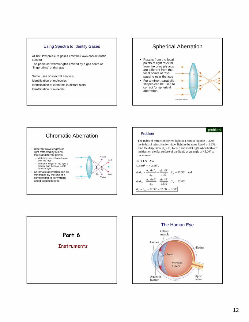
Spherical Aberration
• Results from the focal points of light rays far from the principle axis are different from the focal points of rays passing near the axis
• For a mirror, parabolic shapes can be used to correct for spherical aberration
Chromatic Aberration
• Different wavelengths of light refracted by a lens focus at different points– Violet rays are refracted more
than red rays– The focal length for red light is
greater than the focal length for violet light
• Chromatic aberration can be minimized by the use of a combination of converging and diverging lenses
Problem
The index of refraction for red light in a certain liquid is 1.320; the index of refraction for violet light in the same liquid is 1.332. Find the dispersion (θv – θr) for red and violet light when both are incident on the flat surface of the liquid at an angle of 45.00° to the normal.
1 1 2 2
1 12 2
2
1 12 2
2
2 2
SNELL'S LAWsin
sin sin 45 32.39 and1.32
sin sin 45 32.061.332
32.39 32.06 0.33
r r r
rr r
r
bb b
b
r b
n n sinn
sinn
nsin
n
θ θ
θθ θ
θθ θ
θ θ
=
= = =
= = =
− = − =
oo
oo
o o o
problem
Instruments
Part 6
The Human Eye

13
Simple Magnifying Lens Compound Microscope
MirrorsConvex MirrorObject Image Image Imagelocation orientation size typeArbitrary Upright Reduced Virtual
Concave MirrorObject Image Image Imagelocation orientation size typeBeyond C Inverted Reduced RealC Inverted Same as object RealBetween F & C Inverted Enlarged RealJust beyond F Inverted Approaching Infinity RealJust inside F Upright Approaching Infinity VirtualBetween F & mirror Upright Enlarged Virtual
LensesConcave LensObject Image Image Imagelocation orientation size typeArbitrary Upright Reduced Virtual
Convex LensObject Image Image Imagelocation orientation size typeBeyond F Inverted Reduced or enlarg. RealJust beyond F Inverted Approaching Infinity RealJust inside F Upright Approaching Infinity VirtualBetween F & lens Upright Enlarged Virtual
You look downward at a coin that lies at the bottom of a pool of liquid with depth d and index of refraction n. Because you view with two eyes, which intercept different rays of light from the coin, you perceive the coin to be where extensions of the intercepted rays cross, at depth da instead of d. Assuming that the intercepted rays are close to a vertical axis through the coin, show that da = d/n. (Hint: Use the small-angle approximation that sinθ= tanθ = θ.)
Question
A concave mirror (sometimes surrounded by light) is often used as an aid for applying cosmetics to the face.Why is such a mirror always concave rather than convex?What considerations determine its radius of curvature?
?

14
Question
A person looks at her reflection in the concave side of a shiny spoon.Is this image right side up or inverted?What does she see if she looks in the convex side?
?Figure shows a small plant near a thin lens. The ray shown is one of the principal rays for the lens. Each square is 1.0 cm along the horizontal direction, but the vertical direction is not to the same scale. (a) Using only the ray shown, decide what type of lens this is. (b) What is the focal length of the lens? (c) Locate the image by drawing the other two principal rays, (d) Calculate where the image should be, and compare with solution in (c).
problem
Figure shows a small plant near a thin lens. The ray shown is one of the principal rays for the lens. Each square is 1.0 cm along the horizontal direction, but the vertical direction is not to the same scale. (a) Using only the ray shown, decide what type of lens this is. (b) What is the focal length of the lens? (c) Locate the image by drawing the other two principal rays, (d) Calculate where the image should be, and compare with solution in (c).
problem
Recommended