GE Multilin Connection Technology Center
8/30/2005 Motor Management with Vibration Protection 1
Motor Management with Vibration Protection
Introduction:
Recent advances in motor management and accelerometer technology are
providing a new means for motor protection utilizing dual outputs. Accelerometers are
now available with loop power outputs (4-20 mA), and dynamic signal outputs (100
mV/g). Loop power outputs are compatible with most distributed process control
systems and programmable logic controllers used for process management. The model
#469 Motor Control Relay Manufactured by GE Multilin carries this process one step
further by providing immediate trending and alarming at the motor & controller interface.
These self contained motor management relays can provide process information on many
motor variables such as speed, current, voltage, temperature, and now, with the
introduction of the CTC Dual Output Loop Power Accelerometer, vibration protection
without losing the ability to do dynamic signal (vibration) analysis.
The dynamic signal output is typical of existing vibration analysis technology
used in the field today, and is compatible with existing diagnostic tools. The loop power
output provides a peak or rms. value over a specified frequency band creating a
proportional 4-20 mA signal that can be stored, trended, and alarmed. Changes in the
loop power value will alert the control system or operations department of pending
vibration problems with the motor or driven machine, and can be used to generate an
alarm requiring further detailed analysis or immediate shutdown. Once alerted, the
vibration analyst can use the dynamic output of the accelerometer (100mV/g) to measure,
analyze, and determine root cause of the vibration problem. This integrated approach
GE Multilin Connection Technology Center
8/30/2005 Motor Management with Vibration Protection 2
between Motor Management and Vibration Analysis & Protection is combining the latest
technologies for condition monitoring and reliability.
Using the Motor Management Relay as a Vibration Monitor:
The 469 Motor Management Relay has 4 analog inputs, 4 to 20 mA, 0 to 20 mA,
or 0 to 1 mA as selected. These inputs may be used to monitor sensors such as loop
power accelerometers, tachometers, pressure transducers, or many others available with
typical current outputs used in process applications. Analog inputs can be used for
generating alarms to the control center, or tripping the motor and shutting down the
machine prior to failure. The inputs are sampled every second, and the level of the
analog input is also available over the serial communication port.
The relay is used to monitor the mechanical conditions of either the main
machine, or any associated ancillary equipment, as part of the process. There might be
occasions where a mechanical failure of the associated equipment implies the immediate
removal from service of the main machine.
The 469 Motor Management Relay analog input settings contain two independent
limits: one limit for alarm, and one limit for shutdown or trip. Both levels can be set in
inches/second (velocity) or mils (displacement). In addition, a 4-20 mA output can be
programmed to respond to the same signal provided by the vibration sensor, proportional
to the vibration level, in case that the same signal is required for other purposes such as
local indication.

GE Multilin Connection Technology Center
8/30/2005 Motor Management with Vibration Protection 3
Each analog input may be individually configured to represent a number of
different measured parameters including the analog inputs. The minimum value
programmed represents the 4 mA output, and the maximum value programmed represents
the 20 mA output. If the maximum value is programmed lower than the minimum value,
the output will function in reverse. All four of the outputs are updated once every
second, but each parameter may be used only once.
For example, the analog output parameter may be chosen as the “Analog Input 1’
for a 4 to 20 mA output. If the minimum is set for “0 inches/second”, the analog output
channel will output 4 mA when “Analog Input 1” is measuring 4 mA in response to a
vibration sensor measuring a vibration velocity of 0 inches/second, 12 mA when it is 12
mA or a vibration of velocity of 0.5 inches/second, and 20 mA when it is 20 mA or a
vibration velocity of 1.0 inches/second (based on 4 to 20 mA proportional to 0 to 1
inch/second). The 4 mA current will be present even when there is no vibration, thus
demonstrating that the unit is functioning.
Two auxiliary contacts are also provided. These are dry contacts in the sense that
they are isolated from the input power.
Time delay is available to prevent false tripping due to abnormal vibrations due to
non-repetitive transient events. In addition to that, the Analog Inputs of the 469 Motor
Management Relay can be set to ignore abnormal conditions during the starting sequence
of the machine.
GE Multilin Connection Technology Center
8/30/2005 Motor Management with Vibration Protection 4
Dual Output Loop Power Accelerometers for Vibration Protection & Analysis:
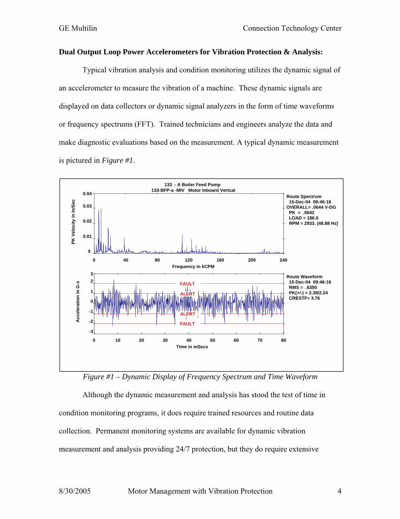
Typical vibration analysis and condition monitoring utilizes the dynamic signal of
an accelerometer to measure the vibration of a machine. These dynamic signals are
displayed on data collectors or dynamic signal analyzers in the form of time waveforms
or frequency spectrums (FFT). Trained technicians and engineers analyze the data and
make diagnostic evaluations based on the measurement. A typical dynamic measurement
is pictured in Figure #1.
Figure #1 – Dynamic Display of Frequency Spectrum and Time Waveform
Although the dynamic measurement and analysis has stood the test of time in
condition monitoring programs, it does require trained resources and routine data
collection. Permanent monitoring systems are available for dynamic vibration
measurement and analysis providing 24/7 protection, but they do require extensive
Route Waveform 15-Dec-04 09:46:16 RMS = .6350 PK(+/-) = 2.39/2.24 CRESTF= 3.76
0 10 20 30 40 50 60 70 80
-3
-2
-1
0
1
23
Time in mSecs
Acc
eler
atio
n in
G-s
ALERT
ALERT
FAULT
FAULT
133 - A Boiler Feed Pump133-BFP-a -MIV Motor Inboard Vertcal
Route Spectrum 15-Dec-04 09:46:16 OVERALL= .0644 V-DG PK = .0642 LOAD = 186.0 RPM = 2933. (48.88 Hz)
0 40 80 120 160 200 240
0
0.01
0.02
0.03
0.04
Frequency in kCPM
PK V
eloc
ity in
In/S
ec
GE Multilin Connection Technology Center
8/30/2005 Motor Management with Vibration Protection 5
hardware/software installation, and technical resources to diagnose and interpret the data
or generate proper alarm settings.
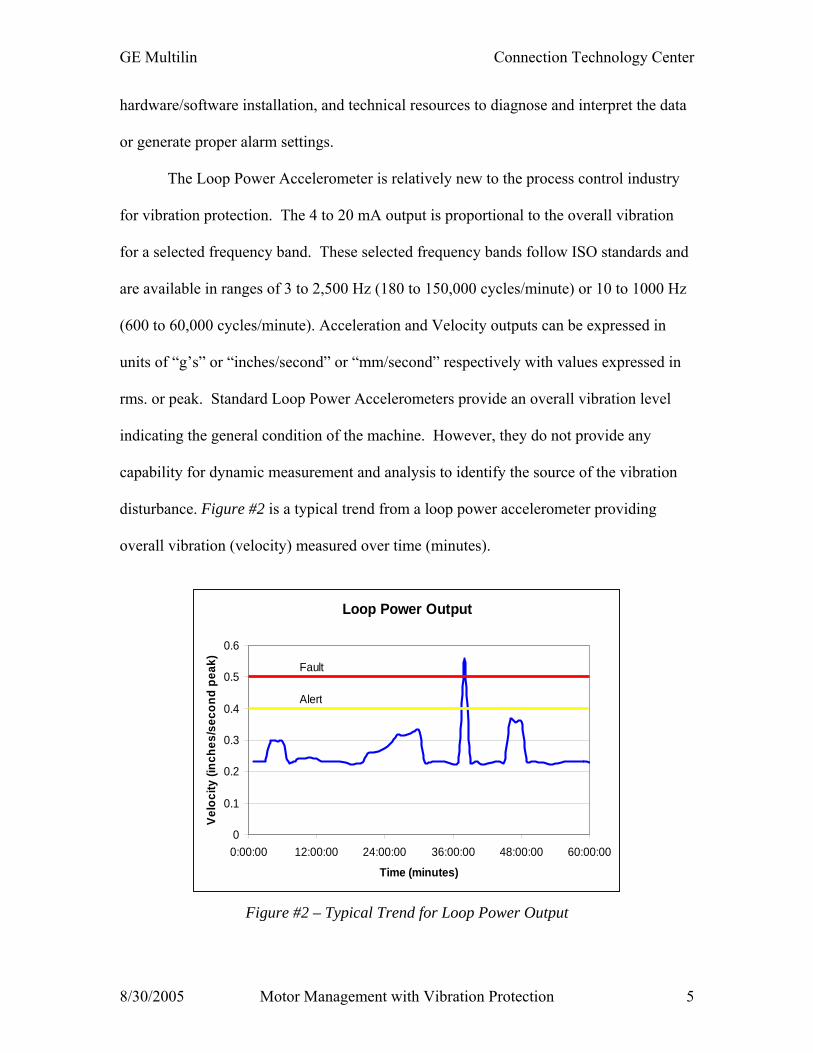
The Loop Power Accelerometer is relatively new to the process control industry
for vibration protection. The 4 to 20 mA output is proportional to the overall vibration
for a selected frequency band. These selected frequency bands follow ISO standards and
are available in ranges of 3 to 2,500 Hz (180 to 150,000 cycles/minute) or 10 to 1000 Hz
(600 to 60,000 cycles/minute). Acceleration and Velocity outputs can be expressed in
units of “g’s” or “inches/second” or “mm/second” respectively with values expressed in
rms. or peak. Standard Loop Power Accelerometers provide an overall vibration level
indicating the general condition of the machine. However, they do not provide any
capability for dynamic measurement and analysis to identify the source of the vibration
disturbance. Figure #2 is a typical trend from a loop power accelerometer providing
overall vibration (velocity) measured over time (minutes).
Figure #2 – Typical Trend for Loop Power Output
Loop Power Output
0
0.1
0.2
0.3
0.4
0.5
0.6
0:00:00 12:00:00 24:00:00 36:00:00 48:00:00 60:00:00
Time (minutes)
Velo
city
(inc
hes/
seco
nd p
eak)
Alert
Fault
GE Multilin Connection Technology Center
8/30/2005 Motor Management with Vibration Protection 6
Dual Output Loop Power Accelerometers provide the best of both worlds. One
output provides 4 to 20 mA for process control, and one output provides dynamic
vibration (100 mV/g or 100 mV/inch/second) for use with the traditional data collectors
and dynamic signal analyzers. Leveraging the dual output capabilities of these sensors
provides an easy method for process control and alarms that can be utilized at the shop
floor level for protection, but still provides the capability for the trained technicians and
engineers to analyze the source of the vibration. Both measurements are performed with
one sensor, reducing the equipment and time required to get the measurement.
Vibration amplitudes for the Loop Power output are available in ranges of 0 to 0.5
inches/second, 0 to 1.0 inches/second, 0 to 2.0 inches/second, 0 to 10 mm/second, or 0 to
20 mm/second. Values are represented as “peak” or “rms.”
Vibration amplitudes for the Dynamic Output will have a range of +/- 50 g’s.
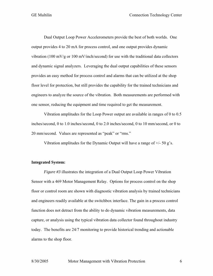
Integrated System:
Figure #3 illustrates the integration of a Dual Output Loop Power Vibration
Sensor with a 469 Motor Management Relay. Options for process control on the shop
floor or control room are shown with diagnostic vibration analysis by trained technicians
and engineers readily available at the switchbox interface. The gain in a process control
function does not detract from the ability to do dynamic vibration measurements, data
capture, or analysis using the typical vibration data collector found throughout industry
today. The benefits are 24/7 monitoring to provide historical trending and actionable
alarms to the shop floor.
GE Multilin Connection Technology Center
8/30/2005 Motor Management with Vibration Protection 7
Figure #3 – Integrated System
Boiler Feed Pump – Case History:
Four CTC Dual Output Loop Power Sensors have been installed on a 600 HP
Boiler Feed Pump Motor running at 2933 rpm. This variable speed motor drive has a GE
Multilin 469 Motor Management Relay incorporated with the drive package. Three
sensors were placed on the motor, on the inboard bearing casing, in the vertical,
horizontal, and axial locations. The fourth sensor was placed on the outboard end of the
Loop Power Output
0
0.1
0.2
0.3
0.4
0.5
0.6
0:00:00 12:00:00 24:00:00 36:00:00 48:00:00 60:00:00
Time (minutes)
Vel
ocity
(inc
hes/
seco
nd p
eak)
Alert
Fault
Route Waveform 15-Dec-04 09:46:16 RMS = .6350 PK(+/-) = 2.39/2.24 CRESTF= 3.76
0 10 20 30 40 50 60 70 80
-3
-2
-1
0
1
23
Time in mSecs
Acc
eler
atio
n in
G-s
ALERT
ALERT
FAULT
FAULT
133 - A Boiler Feed Pump133-BFP-a -MIV Motor Inboard Vertcal
Route Spectrum 15-Dec-04 09:46:16 OVERALL= .0644 V-DG PK = .0642 LOAD = 186.0 RPM = 2933. (48.88 Hz)
0 40 80 120 160 200 240
0
0.01
0.02
0.03
0.04
Frequency in kCPM
PK V
eloc
ity in
In/S
ec
Dual Output Loop Power Sensors (Accelerometers)
Switch Box
Dynamic Vibration
Process Control
Motor Management Relay

GE Multilin Connection Technology Center
8/30/2005 Motor Management with Vibration Protection 8
motor in the vertical location between cooling fins (fin mount). Figure #4 identifies each
sensor location and orientation on the motor.
Figure #4 – Sensor Mounting Locations
Inboard Vertical (IV)
Inboard Horizontal (IH)
Inboard Axial (IA)
Outboard Vertical (OV)

GE Multilin Connection Technology Center
8/30/2005 Motor Management with Vibration Protection 9
Process Data:
Data has been collected for process control using the 4-20 mA features of the GE
Multilin 469 Motor Management Relay. Figure #5 is a trend chart representing 1,600
samples for July 27, 2005. The “X” scale represents approximately 27 minutes of data
sampled once/second.
Boiler Feed Pump 27Jul05
0
200
400
600
800
1000
1200
1400
0 200 400 600 800 1000 1200 1400 1600
Points
mill
i-inc
hes/
seco
nd p
k
OVIVIHIA
Figure #5 – Trend of Loop Power Output
It is easy to detect the transient that has occurred in the trend. All four of the
vibration sensors have shifted to zero output and then recovered to the normal operating
condition. The process data can be expanded around this transient, and is illustrated in
Figure #6.
GE Multilin Connection Technology Center
8/30/2005 Motor Management with Vibration Protection 10
Boiler Feed Pump 27Jul05
0
200
400
600
800
1000
1200
1400
725 735 745 755 765 775 785 795 805 815 825
Points
mill
i-inc
hes/
seco
nd p
k
0
10
20
30
40
50
60
70
80
Am
ps
OVIVIHIACurrent "A"
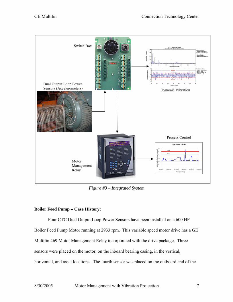
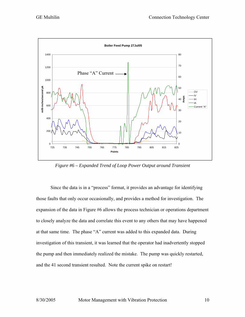
Figure #6 – Expanded Trend of Loop Power Output around Transient
Since the data is in a “process” format, it provides an advantage for identifying
those faults that only occur occasionally, and provides a method for investigation. The
expansion of the data in Figure #6 allows the process technician or operations department
to closely analyze the data and correlate this event to any others that may have happened
at that same time. The phase “A” current was added to this expanded data. During
investigation of this transient, it was learned that the operator had inadvertently stopped
the pump and then immediately realized the mistake. The pump was quickly restarted,
and the 41 second transient resulted. Note the current spike on restart!
Phase “A” Current

GE Multilin Connection Technology Center
8/30/2005 Motor Management with Vibration Protection 11
Dynamic Data:
Not to be forgotten, the dynamic vibration data can also be measured and
analyzed for the four dual output vibration sensors. This data will be typical of the
vibration measurements made during normal “route” based data collection. Functionally
the dual output sensors create a permanently mounted vibration sensor, and by utilizing
the switchbox, allow the portable measurements as shown in Figures #7 - #10.
Outboard Vertical
0
0.02
0.04
0.06
0.08
0.1
0 500 1000 1500 2000 2500
Hz
Inch
/Sec
ond
pk
Figure #7 – Outboard Vertical Vibration
Inboard Vertical
0
0.02
0.04
0.06
0.08
0.1
0 500 1000 1500 2000 2500
Hz
Inch
/Sec
ond
pk
Figure #8 – Inboard Vertical Vibration

GE Multilin Connection Technology Center
8/30/2005 Motor Management with Vibration Protection 12
Inboard Horizontal
0
0.05
0.1
0.15
0.2
0 500 1000 1500 2000 2500
Hz
Inch
/Sec
ond
pk
Figure #9 – Inboard Horizontal Vibration
Inboard Axial
0
0.02
0.04
0.06
0.08
0.1
0 500 1000 1500 2000 2500
Hz
Inch
/Sec
ond
pk
Figure #10 – Inboard Axial Vibration
The FFT’s of Figures #7 - #10 are typical of dynamic vibration that would have
historically been collected periodically on a route based program. Utilizing the dual
output sensors retains this feature with permanent accelerometers that also provide
process alarms through the motor management relay.
GE Multilin Connection Technology Center
8/30/2005 Motor Management with Vibration Protection 13
Summary:
• The GE Multilin model 469 Motor Management Relay provides an excellent
platform for utilizing 4-20 mA outputs in a process control environment.
• The CTC Dual Output Loop Power Accelerometer provides 4-20 mA outputs for
process control in conjunction with 100 mV/g dynamic vibration outputs.
• Trending and alarming is available in typical process control formats for use by
the operations and maintenance departments.
• Dynamic vibration measurement and analysis is available for the vibration team
providing diagnostic support for process disturbances.
• Successful Process Control and Vibration Programs co-exist!
Jack D. Peters Regional Manager (Asia/Pacific, Canada, South Africa) Category IV, ISO 18436-2, Vibration Analyst CTC - Connection Technology Center, Inc. 590 Fishers Station Drive Victor, N.Y. 14564 Phone: 1-800-999-5290, ext. 834 (US & Canada) Fax: 1-585-924-4680 E-mail: [email protected] website: www.ctconline.com
Rene΄ Midence Product Manager GE Consumer & Industrial – Multilin 215 Anderson Avenue Markham, ON, Canada L6E 1B3 Phone: 1-905-201-2143 Fax: 1-905-201-2098 E-mail:[email protected] website: www.GEMultilin.com
Recommended