MIL-STD-1530D 31 August 2016 SUPERSEDING MIL-STD-1530C (USAF) 1 November 2005
DEPARTMENT OF DEFENSE STANDARD PRACTICE
AIRCRAFT STRUCTURAL INTEGRITY PROGRAM (ASIP)
AMSC N/A FSC 15GP
Distribution Statement A. Approved for public release; distribution is unlimited.
NOT MEASUREMENT SENSITIVE
Downloaded from http://www.everyspec.com
MIL-STD-1530D
ii
FOREWORD
1. This standard is approved for use by all Departments and Agencies of the Department of Defense (DoD).
2. This standard implements Air Force Policy Directive (AFPD) 63-1, Acquisition and Sustainment Life Cycle Management, Air Force Instruction (AFI) 63-101, Acquisition and Sustainment Life Cycle Management and AFI 63-140, Aircraft Structural Integrity Program. These three documents define policies, procedures, and responsibilities that ensure the safe operation of USAF aircraft. The requirements of these three documents are not repeated in higher-level policy (for example, DoD-5000 Series documents) and have no commercial equivalent (for example, Federal Aviation Administration [FAA] regulations).
3. Comments, suggestions, or questions on this document should be addressed to AFLCMC/EZSS, Bldg 28, 2145 Monahan Way, Wright-Patterson AFB OH 45433-7017 or emailed to AFLCMC/EN EZ Engineering [email protected]. Since contact information can change, you may want to verify the currency of this address information using the ASSIST Online database at https://assist.dla.mil.
Downloaded from http://www.everyspec.com
MIL-STD-1530D
iii
CONTENTS 1. SCOPE ................................................................................................................................ 1 1.1 ASIP goal and objectives. ................................................................................................... 1 1.2 ASIP primary tasks. ............................................................................................................. 2 2. APPLICABLE DOCUMENTS ........................................................................................... 2 2.1 General. ............................................................................................................................... 2 2.2 Government documents. ...................................................................................................... 2 2.2.1 Specifications, standards, and handbooks. .......................................................................... 2 2.2.2 Other Government documents, drawings, and publications. ............................................... 3 2.3 Non-Government publications. ........................................................................................... 4 2.4 Order of precedence. ........................................................................................................... 5 3. DEFINITIONS .................................................................................................................... 5 3.1 Aircraft structure. ................................................................................................................ 5 3.2 Baseline operational loads/environment spectrum (baseline spectrum). ............................. 5 3.3 Certification. ........................................................................................................................ 5 3.4 Certified service life. ........................................................................................................... 5 3.5 Corrosion. ............................................................................................................................ 5 3.6 Damage. ............................................................................................................................... 5 3.7 Damage arrest. ..................................................................................................................... 6 3.8 Damage tolerance. ............................................................................................................... 6 3.9 Design loads/environment spectrum (design spectrum). ..................................................... 6 3.10 Design service life. .............................................................................................................. 6 3.11 Durability. ........................................................................................................................... 6 3.12 Durability-critical part. ........................................................................................................ 6 3.13 Economic service life. ......................................................................................................... 6 3.14 Equivalent flight hours. ....................................................................................................... 6 3.15 Equivalent initial damage size (EIDS) distribution. ............................................................ 6 3.16 Fail-safe. .............................................................................................................................. 7 3.17 Fail-safe life limit. ............................................................................................................... 7 3.18 Fracture-critical part. ........................................................................................................... 7 3.19 Fracture-critical traceable part. ............................................................................................ 7 3.20 Inspectability. ...................................................................................................................... 7 3.21 Multiple load path. .............................................................................................................. 7 3.22 Nondestructive inspection (NDI). ....................................................................................... 7 3.23 Normal controls part. ........................................................................................................... 7 3.24 Onset of widespread fatigue damage (WFD). ..................................................................... 7 3.25 Probability of detection (POD). ........................................................................................... 8 3.26 Producibility. ....................................................................................................................... 8 3.27 Residual strength. ................................................................................................................ 8 3.28 Structural risk analysis. ....................................................................................................... 8 3.29 Rotorcraft dynamic component. .......................................................................................... 8
Downloaded from http://www.everyspec.com
MIL-STD-1530D
iv
3.30 Safe-life. .............................................................................................................................. 8 3.31 Safe-life limit. ...................................................................................................................... 8 3.32 Safety-of-flight structure. .................................................................................................... 8 3.33 Single load path. .................................................................................................................. 8 3.34 Slow damage growth. .......................................................................................................... 9 3.35 Structural health monitoring (SHM). .................................................................................. 9 3.36 Structural integrity. .............................................................................................................. 9 3.37 Supportability. ..................................................................................................................... 9 4. GENERAL REQUIREMENTS......................................................................................... 10 4.1 Aircraft MDS developed or modified by the USAF. ........................................................ 10 4.2 Aircraft MDS operated by the USAF but not developed or modified by the USAF. ........ 10 5. DETAILED REQUIREMENTS ....................................................................................... 12 5.1 Design information (Task I). ............................................................................................. 12 5.1.1 ASIP Master Plan. ............................................................................................................. 12 5.1.2 Design service life and design usage. ................................................................................ 12 5.1.3 Structural design criteria. .................................................................................................. 12 5.2.1 Durability and damage tolerance control. ......................................................................... 15 5.1.5 Corrosion prevention and control. ..................................................................................... 16 5.1.6 Selection of materials, processes, joining methods, and structural concepts. ................... 17 5.2 Design analyses & development testing (Task II). ............................................................ 19 5.2.1 Material and structural allowables. .................................................................................... 19 5.2.2 Loads analysis. .................................................................................................................. 19 5.2.3 Design loads/environment spectra. .................................................................................... 19 5.2.4 Stress and strength analysis. .............................................................................................. 20 5.2.5 Durability analysis. ............................................................................................................ 20 5.2.6 Damage tolerance analysis. ............................................................................................... 20 5.2.7 Corrosion assessment. ....................................................................................................... 20 5.2.8 Sonic fatigue analysis. ....................................................................................................... 21 5.2.9 Vibration analysis. ............................................................................................................. 21 5.2.10 Aeroelastic and aeroservoelastic analysis. ........................................................................ 21 5.2.11 Mass properties analysis. ................................................................................................... 21 5.2.12 Survivability analysis. ....................................................................................................... 21 5.2.13 Design development tests. ................................................................................................. 22 5.2.14 Structural risk analysis. ..................................................................................................... 23 5.2.15 Economic service life analysis. ......................................................................................... 23 5.3 Full-scale testing (Task III). .............................................................................................. 23 5.3.1 Static tests. ......................................................................................................................... 23 5.3.2 First flight verification ground tests. ................................................................................. 25 5.3.3 Flight tests. ........................................................................................................................ 26 5.3.4 Durability tests. ................................................................................................................. 27 5.3.5 Damage tolerance tests. ..................................................................................................... 29
Downloaded from http://www.everyspec.com
MIL-STD-1530D
v
5.3.6 Climatic tests. .................................................................................................................... 29 5.3.7 Interpretation and evaluation of test findings. ................................................................... 29 5.3.8 Resolution of test findings. ................................................................................................ 29 5.4 Certification & force management development (Task IV). ............................................. 30 5.4.1 Structural certification. ...................................................................................................... 30 5.4.2 Strength Summary & Operating Restrictions (SSOR). ..................................................... 30 5.4.3 Force Structural Maintenance Plan (FSMP). ..................................................................... 30 5.4.4 Loads/Environment Spectra Survey (L/ESS) system development. ................................. 31 5.4.5 Individual Aircraft Tracking (IAT) system development. ................................................. 32 5.4.6 Force management database development. ....................................................................... 32 5.4.7 Technical Orders (TOs). .................................................................................................... 33 5.5 Force management execution (Task V). ............................................................................ 33 5.5.1 L/ESS execution. ............................................................................................................... 33 5.5.2 IAT execution. ................................................................................................................... 33 5.5.3 DADTA updates. ............................................................................................................... 34 5.5.4 L/ESS and IAT system updates. ........................................................................................ 34 5.5.5 NDI updates. ...................................................................................................................... 34 5.5.6 Structural risk analysis updates. ........................................................................................ 34 5.5.7 CPCP and corrosion assessment updates. ......................................................................... 35 5.5.8 Analytical Condition Inspection (ACI). ............................................................................ 35 5.5.9 FSMP updates.................................................................................................................... 35 5.5.10 Technical Order (TO) updates. .......................................................................................... 35 5.5.11 Repairs. .............................................................................................................................. 35 5.5.12 Force management database execution. ............................................................................ 35 5.5.13 Structural certification updates. ......................................................................................... 35 5.5.14 Economic service life analysis updates. ............................................................................ 36 5.5.15 Others as required. ............................................................................................................. 36 6. NOTES .............................................................................................................................. 37 6.1 Intended use. ...................................................................................................................... 37 6.2 Acquisition requirements. ................................................................................................. 37 6.3 Data requirements. ............................................................................................................. 37 6.4 Subject term (key word) listing. ........................................................................................ 38 6.5 Changes from previous issue. ............................................................................................ 39
TABLE TABLE I. USAF Aircraft Structural Integrity Program Tasks. ......................................................... 11
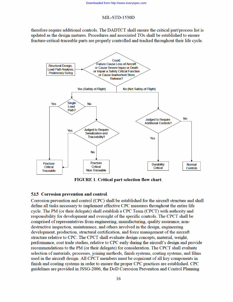
FIGURE FIGURE 1. Critical part selection flow chart. ................................................................................... 16
Downloaded from http://www.everyspec.com
MIL-STD-1530D
1
1. SCOPE This standard describes the USAF Aircraft Structural Integrity Program (ASIP) which defines the requirements necessary to achieve structural integrity in USAF aircraft while managing cost and schedule risks through a series of disciplined, time-phased tasks. It provides direction to government personnel and contractors engaged in the development, production, structural certification, modification, acquisition, and/or sustainment of USAF aircraft. This standard applies to the entire structure of an aircraft, as defined in section 3.1, regardless of aircraft type or procurement strategy, for the entire life cycle of the aircraft.
1.1 ASIP goal and objectives. The effectiveness of any military force depends, in part, on the safety and operational readiness of its weapon systems. One major item of an aircraft system that affects its safety and operational readiness is the condition of the aircraft structure. Potential structural or material problems must be identified and corrected early in the life-cycle to minimize their impact on the operational force. In addition, a preventive maintenance program must be developed and implemented to provide for orderly-scheduled and efficient inspections, repairs, modifications, or component replacements of the aircraft structure. The overall program to provide USAF aircraft with the required aircraft structural characteristics is referred to as the Aircraft Structural Integrity Program, or “ASIP.”
The goal of the ASIP is to ensure the desired level of structural safety, performance, durability, and supportability with the least possible economic burden throughout the aircraft’s service life.
The objectives of the ASIP are to:
1. Define the structural integrity requirements necessary to support airworthiness assurance and the program manager’s assurance of Operational Safety, Suitability, and Effectiveness.
2. Establish, evaluate, substantiate, and certify the structural integrity of aircraft structures.
3. Acquire, evaluate, and apply usage and maintenance data to ensure the continued structural integrity of operational aircraft.
4. Provide quantitative information for decisions on force structure planning, inspection, modification priorities, risk management, expected life cycle costs, and related operational and support issues, and
5. Provide a basis to improve structural criteria and methods of design, evaluation, and substantiation for future aircraft systems and modifications.
Downloaded from http://www.everyspec.com

MIL-STD-1530D
2
1.2 ASIP primary tasks. The ASIP consists of the following five, interrelated tasks as delineated in TABLE I:
1. Task I (Design Information). Task I consists of establishing those criteria and other requirements which must be applied during design to ensure the overall program goals will be met.
2. Task II (Design Analyses and Development Testing). Task II consists of the characterization of the environment in which the aircraft must operate, the testing of materials, components, and assemblies, and the analyses of the aircraft design.
3. Task III (Full-Scale Testing). Task III consists of laboratory and flight tests of the aircraft structure to assist in determining the structural adequacy of the analysis and design.
4. Task IV (Certification and Force Management Development). Task IV consists of the analyses that lead to certification of the aircraft structure as well as the development of the processes and procedures that will be used to manage force operations when the aircraft enters the inventory.
5. Task V (Force Management Execution). Task V consists of the execution of the processes and procedures developed under Task IV to ensure structural integrity throughout the life of each individual aircraft. This task may involve revisiting elements of earlier tasks, particularly if the service life requirement is extended, if the operational usage is different than the design spectrum, or if the aircraft is modified.
2. APPLICABLE DOCUMENTS
2.1 General. The documents listed in this section are specified in sections 3, 4, or 5 of this standard. This section does not include documents cited in other sections of this standard or recommended for additional information or as examples. While every effort has been made to ensure the completeness of this list, document users are cautioned that they must meet all specified requirements of documents cited in sections 3, 4, or 5 of this standard, whether or not they are listed.
2.2 Government documents. 2.2.1 Specifications, standards, and handbooks. The following specifications, standards, and handbooks form a part of this document to the extent specified herein. Unless otherwise specified, the issues of these documents are those cited in the solicitation or contract.
DEPARTMENT OF DEFENSE Specifications JSSG-2006 Aircraft Structures
Standards MIL-STD-882 Standard Practice for System Safety
Downloaded from http://www.everyspec.com

MIL-STD-1530D
3
MIL-STD-1568 Materials and Processes for Corrosion Prevention and Control in Aerospace Weapon Systems
Handbooks MIL-HDBK-1587 Materials and Process Requirements for Air Force
Weapon Systems
MIL-HDBK-1823 Nondestructive Evaluation System, Reliability Assessment
MIL-HDBK-6870 Inspection Program Requirements, Nondestructive, for Aircraft and Missile Materials and Parts
(Copies of these documents are available online at http://quicksearch.dla.mil.)
2.2.2 Other Government documents, drawings, and publications. The following other Government documents, drawings, and publications form a part of this document to the extent specified herein. Unless otherwise specified, the issues of these documents are those cited in the solicitation or contract.
Department of Defense Policy Directives and Instructions
DFARS 207.105(b)(13)(ii) Oct 04 Defense Federal Acquisition Regulation, Part 207-Acquisition Planning, Subpart 207.1-Acquisition Plans
DoD Corrosion Prevention and Control Planning Guidebook
(Copies of DFARS Part 207 are available online at: http://farsite.hill.af.mil/reghtml/regs/far2afmcfars/fardfars/dfars/dfars207.htm.)
(Copies of the DoD Corrosion Prevention and Control Planning Guidebook are available at: https://www.corrdefense.org/External/ReferenceLibrary.aspx.)
U.S. Air Force Policy Directives and Instructions AFPD 63-1 Integrated Life Cycle Management
AFI 63-101 Integrated Life Cycle Management
AFI 63-140 Aircraft Structural Integrity Program
AFI 62-601 USAF Airworthiness
AFMCI 21-102 Analytical Condition Inspection (ACI) Programs
(Copies of Directives and Instructions are available from the U.S. Air Force Publications Distribution Center, 2800 Eastern Blvd, Baltimore MD 21220-2898; [410] 687-3330; http://www.e-publishing.af.mil/index.asp.)
U.S. Air Force Technical Orders T.O. 1-1B-50 Basic Technical Order for USAF Aircraft Weight and
Balance
Downloaded from http://www.everyspec.com
MIL-STD-1530D
4
Federal Aviation Administration
MMPDS-Handbook Metallic Material Properties Development and Standardization
CMH-17 Composite Materials Handbook
(Copies are available from Battelle Memorial Institute, 505 King Avenue, Columbus OH 43201-2681; [614] 424-5000.)
U.S. Air Force Technical Reports
WL-TR-94-4052/3/4/5/6 (Accession Number ADA311686/87/88/89/90)
Damage Tolerant Design Handbook (5 Volumes)
http://www.dtic.mil./dtic/ Damage Tolerant Design Handbook: Guidelines for the Analysis and Design of Damage Tolerant Aircraft Structures
(Copies of the five-volume DT Design Data Handbook are available from the Defense Technical Information Center [DTIC], 8725 John J. Kingman Road, Suite 0944, Fort Belvoir VA 22060-6218, 1-800-CAL-DTIC, http://www.dtic.mil./dtic/; and from the Center for Information and Numerical Data Analysis and Synthesis (CINDAS); https://cindasdata.com).
(Copies of U.S Air Force Structural Bulletins are available from AFLCMC/EZSS, Bldg. 28, 2145 Monahan Way, Wright-Patterson AFB, OH 45433-7017; 937-904-5476; [email protected].)
2.3 Non-Government publications. The following documents form a part of this document to the extent specified herein. Unless otherwise specified, the issues of these documents are those cited in the solicitation or contract.
Center for Information and Numerical Data Analysis and Synthesis (CINDAS)
CINDAS Aerospace Structural Metals Handbook (6 Volumes)
CINDAS Structural Alloys Handbook (3 Volumes)
(Copies are available from Center for Information and Numerical Data Analysis and Synthesis (CINDAS), https://cindasdata.com).
International Society of Allied Weight Engineers, Inc.
SAWE RP No. 7 Mass Properties Management and Control for Military Aircraft
(Copies of T.O.s are available from Oklahoma City Air Logistics Center (OC-ALC/LGLDT); 3001 Staff Drive STE 1AB1 100; Tinker AFB OK 73145-3042; [405] 736-3779; http://www.tinker.af.mil/technicalorders/.)
Downloaded from http://www.everyspec.com
MIL-STD-1530D
5
(Copies are available from Society of Allied Weight Engineers, P.O. Box 60024, Terminal Annex, Los Angeles CA 90060-0024, http://www.sawe.org.)
2.4 Order of precedence. Unless otherwise noted herein or in the contract, in the event of a conflict between the text of this document and the references cited herein, the text of this document takes precedence. Nothing in this document, however, supersedes applicable laws and regulations unless a specific exemption has been obtained.
3. DEFINITIONS
3.1 Aircraft structure. Aircraft structure is those components that are required to carry loads in order to properly perform their intended functions. The structure of an aircraft includes the wing, fuselage, empennage, flight control surfaces (for example, flap, aileron, rudder, elevator, speedbrakes, and spoilers), leading edges, trailing edges, radomes, inlets, nacelles, engine mounts, stores mounts, landing gear structural components, rotorcraft rotor and drive systems, and other components as described in the contract specification.
3.2 Baseline operational loads/environment spectrum (baseline spectrum). The baseline operational loads/environment spectrum is an update of the design spectrum based on measured data from operational aircraft (for example, data obtained from the initial or subsequent loads/environment spectra survey).
3.3 Certification. Certification is a repeatable process implemented to verify an aircraft configuration can be safely maintained and operated within its described operational envelope throughout the certified service life.
3.4 Certified service life. The certified service life is the service life limit documented in the airworthiness certificate.
3.5 Corrosion. Corrosion is the deterioration of a material or its properties due to the reaction of that material with its chemical environment.
3.6 Damage. Damage to aircraft structure is any flaw, defect, crack, corrosion, disbond, delamination, discontinuity, or other type that degrades, or has the potential to degrade, the performance of the affected component. Damage can be inherent in the material, introduced during manufacturing, created during normal and abnormal operations and maintenance, or caused by material degradation.
Downloaded from http://www.everyspec.com
MIL-STD-1530D
6
3.7 Damage arrest. Damage arrest is the containment or termination of rapid damage propagation by structural features or structural arrangements which serve this purpose.
3.8 Damage tolerance. Damage tolerance is the attribute of an aircraft structure that permits it to retain its required residual strength in the presence of damage for a period of unrepaired usage.
3.9 Design loads/environment spectrum (design spectrum). The design loads/environment spectrum is the spectrum of external loads and environments (for example, chemical, thermal) used in the design of the aircraft and is representative of the spectrum that the typical force aircraft is expected to encounter within the design service life.
3.10 Design service life. The design service life is the number of years, flight hours, flight cycles, landings established during design, in which the structure is expected to maintain its structural integrity when flown to the design loads/environment spectrum and maintained as required.
3.11 Durability. Durability is the attribute of an aircraft structure that permits it to resist cracking, corrosion, thermal degradation, delamination, wear, and the effects of foreign object damage for a prescribed period of time.
3.12 Durability-critical part. As shown on FIGURE 1, a durability-critical part is a non-safety-of-flight structural component that is judged to require additional controls beyond those for normal-controls parts.
3.13 Economic service life. The economic service life is the period during which it is more cost-effective to maintain, repair, and modify an aircraft component or aircraft than to replace it. Economic service life can be applied to an aircraft component, aircraft, or force basis.
3.14 Equivalent flight hours. Equivalent flight hours are the actual flight hours accumulated by an aircraft that have been modified by a factor that accounts for the difference between the severity of the aircraft’s actual usage and the severity of the design or baseline spectrum.
3.15 Equivalent initial damage size (EIDS) distribution. The equivalent initial damage size distribution is an analytical characterization of the initial quality of the aircraft structure at the time of manufacture, modification, or repair. The EIDS distribution is derived by analytically determining the initial damage size distribution that characterizes the measured damage size distribution observed during test or in service.
Downloaded from http://www.everyspec.com
MIL-STD-1530D
7
3.16 Fail-safe. Fail-safe is a damage tolerance design concept in which structure retains its required residual strength for a period of unrepaired usage after load path failure or partial failure, up to the fail-safe life limit.
3.17 Fail-safe life limit. The fail-safe life limit is the point when the onset of widespread fatigue damage has jeopardized fail-safety of fail-safe structure by the specified margin or factor, or when the required residual strength is not retained after the failure or partial failure of a load path.
3.18 Fracture-critical part. As shown on FIGURE 1, a fracture-critical part is a safety-of-flight structural component that is not single load path nor judged to require serialization and traceability.
3.19 Fracture-critical traceable part. As shown on FIGURE 1, a fracture-critical traceable part is a safety-of-flight structural component that is either single load path or judged to require serialization and traceability.
3.20 Inspectability. Inspectability refers to the ability to reliably detect damage using inspection procedures that meet the minimum probability of detection requirements.
3.21 Multiple load path. Multiple load path is structural redundancy in which the applied loads are distributed to other load-carrying members in the event of failure of individual parts.
3.22 Nondestructive inspection (NDI). Nondestructive inspection is an inspection process or technique designed to reveal the damage at or beneath the external surface of a part or material without adversely affecting the material or part being inspected. NDI generally refers to inspections that are conducted using equipment that is not part of or permanently affixed to the part being inspected. Inspections that do involve such equipment are generally referred to as in-situ NDI or structural health monitoring.
3.23 Normal controls part. As shown on FIGURE 1, a normal-controls part is a non-safety-of-flight structural component where standard aerospace practices are sufficient in the design, manufacturing, and maintenance of the part to ensure structural integrity.
3.24 Onset of widespread fatigue damage (WFD). Onset of widespread fatigue damage is the point at which there is damage of sufficient size and density such that the structure will no longer meet its damage tolerance requirement (for example, maintaining required residual strength after load path failure or partial failure) by the specified margin.
Downloaded from http://www.everyspec.com
MIL-STD-1530D
8
3.25 Probability of detection (POD). A POD is a statistical measurement of the likelihood, with a specified confidence level, of finding damage of a defined size on a specific part and location using a specific inspection or structural health monitoring technique.
3.26 Producibility. Producibility refers to the ability to economically manufacture, fabricate, assemble, and inspect materials, parts, components, and structures that achieve required performance, quality, and production rate.
3.27 Residual strength. Residual strength is the load carrying capability of damage tolerance structure that has or has the potential to contain damage.
3.28 Structural risk analysis. Structural risk analysis is an evaluation of a potential structural hazard severity and probability of occurrence. Potential structural hazards include structural failures that can cause injury or death to personnel, damage to or loss of the aircraft, dropped objects in flight, or reduction of mission readiness/availability.
3.29 Rotorcraft dynamic component. A rotorcraft dynamic component is a structural part of the rotorcraft’s drive train or lift system that is designed for dynamic loading.
3.30 Safe-life. Safe-life is a design concept in which damage does not initiate in the structure and the structure maintains its design ultimate load capability up to the safe-life limit.
3.31 Safe-life limit. Safe-life limit of a structure is the point where the safe-life has been reached and the structure must be replaced or the aircraft must be retired.
3.32 Safety-of-flight structure. Safety-of-flight structure is structure whose failure could cause loss of the aircraft, or cause severe injury or death, or impair a safety critical function, or cause inadvertent store release. The consequences could occur either immediately upon failure or subsequently if the failure remains undetected.
3.33 Single load path. Single load path refers to a structural element or member which acts alone in carrying an applied load. This type of structure does not have multiple or redundant load paths. The failure of this type of structure will result in the loss of the structural capability to carry the applied loads.
Downloaded from http://www.everyspec.com
MIL-STD-1530D
9
3.34 Slow damage growth. Slow damage growth is a damage tolerance design concept in which damage is not allowed to attain the size where unstable rapid damage propagation may occur during the period between maintenance actions such as inspections and repairs.
3.35 Structural health monitoring (SHM). Structural health monitoring is a nondestructive inspection process or technique that uses in-situ sensing devices to detect damage.
3.36 Structural integrity. Structural integrity is the attribute which exists when a structure is sound and unimpaired while providing the desired level of structural safety, performance, durability, and supportability.
3.37 Supportability. Supportability means that thermal, environmental, and mechanical deterioration of structures have been identified and that acceptable quality and cost-effective preventive methods and/or in-service repair methods are either available or can be developed in a timely manner.
Downloaded from http://www.everyspec.com
MIL-STD-1530D
10
4. GENERAL REQUIREMENTS Air Force Policy Directive 63-1 states that the Air Force shall apply integrity programs to weapon systems. Air Force Instruction 63-101 states that the Program Manager (PM) shall establish an ASIP for each Mission Design Series (MDS) the USAF acquires, uses, or leases. Air Force Instruction 63-140 describes the roles and responsibilities for the organizations and individuals involved in ASIP development and execution of all USAF aircraft programs. The five, interrelated ASIP tasks and their corresponding detailed requirements are summarized in TABLE I.
4.1 Aircraft MDS developed or modified by the USAF. For each aircraft MDS developed or modified by the USAF, the ASIP shall comply with this Standard and the PM shall:
a. Draft an initial ASIP Master Plan for the program as early as possible in the Technology Maturation and Risk Reduction phase. The initial ASIP Master Plan shall identify the tasks required to achieve structural integrity and to determine structural safety, performance, durability, supportability, and life cycle costs for the aircraft structure.
b. Obtain Program Executive Officer (PEO) approval for the ASIP Master Plan before the System Requirements Review (SRR).
c. Update the ASIP Master Plan during the Engineering and Manufacturing Development, Production & Deployment, and Operations & Sustainment phases of the program to document changes in the ASIP.
d. Execute the ASIP, for aircraft in sustainment, as an integral part of the total system engineering and management effort in the sustainment of the aircraft.
e. Develop a revised ASIP Master Plan and obtain PEO approval of the revised plan, for aircraft that are to be modified, fly new missions, or whose operation will extend past the aircraft’s certified service life; before modifications are executed, regular flights begin under the new mission, or commencing operations beyond the previously certified service life.
4.2 Aircraft MDS operated by the USAF but not developed or modified by the USAF. For each aircraft MDS operated by the USAF but not developed or modified by the USAF, the PM shall use this standard as the basis for determining those ASIP tasks and elements necessary to ensure the aircraft’s structural safety, performance, durability, supportability, and affordability for the operational life of structural components, while remaining consistent with the program’s acquisition strategy and engineering authority over the aircraft. For these MDS, the PM shall:
a. Document the tailored program in an ASIP Master Plan. b. Finalize the ASIP Master Plan and obtain PEO approval before the Air Force
operates the aircraft.
Downloaded from http://www.everyspec.com

Downloaded from http://www.everyspec.com
MIL-STD-1530D
12
5. DETAILED REQUIREMENTS Detailed guidance for the establishment and verification of aircraft structural requirements and for the planning and execution of ASIP tasks is documented in JSSG-2006 and Structures Bulletins published by the USAF.
5.1 Design information (Task I). The design information task encompasses those efforts required to apply the existing theoretical, experimental, applied research, and operational experience to specific criteria for materials and processes selection to include design, production, sustainment, and retirement/disposal. The objective is to ensure appropriate criteria and planned usage characteristics are applied to an aircraft’s design to meet specific operational, performance, and sustainment requirements throughout the aircraft life cycle.
5.1.1 ASIP Master Plan. The PM shall translate the requirements defined by this standard and AFI 63-140 into a program for each aircraft and document these in the ASIP Master Plan. This plan shall be integrated into the Integrated Master Plan (IMP) and Integrated Master Schedule (IMS). The purpose of the ASIP Master Plan is to define and document the specific approach to accomplish the various ASIP tasks throughout the life-cycle of each individual aircraft. The plan shall depict the time-phased scheduling and integration of all required ASIP tasks for design, development, production, structural certification, and force management of the aircraft structure. The plan shall also include discussion of unique features, exceptions to this standard and the associated rationale including risk assessments, and any problems anticipated in the execution of the plan. The development of the schedule shall consider all interfaces, the impact of schedule delays (for example, delays due to test failure), mechanisms for recovery programming, and other potential problem areas.
5.1.2 Design service life and design usage. The USAF shall provide the design service life and design usage/environments as part of the contract. These data shall be used in the initial design and analysis for strength, rigidity, durability, corrosion prevention and control, and damage tolerance. The design service life and design loads/environment spectrum shall be established through close coordination between the acquisition and operational organizations. Design mission profiles, mission mixes, environmental exposure mixes, and exceedance data which are realistic estimates of expected service usage shall be established based on aircraft requirements.
5.1.3 Structural design criteria. Detailed structural design criteria for the aircraft shall be established in accordance with the requirements of the applicable contracts. These shall include design criteria for loads, dynamics, strength, durability, damage tolerance, mass properties, and other as specified.
5.1.3.1 Loads criteria. Criteria shall be established such that all design limit loads include the maximum, minimum and most critical combination of loads that can result from authorized ground and flight loading conditions for the air vehicle. These include loads during piloted or autonomous maneuvers, loss of control maneuvers, gusts, pressurization, turbulence, take-off, landing, arrestments (if applicable), ground operations, maintenance activity, systems failures from which recovery is expected (to include rapid depressurization) and all loads necessary to
Downloaded from http://www.everyspec.com

MIL-STD-1530D
13
achieve a probability of detrimental deformation at or below 10-5 per flight and a probability of catastrophic failure at or below 10-7 per flight over the design service life and usage. Design ultimate loads for the aircraft shall be obtained by multiplying the design limit loads by the appropriate factor of safety or shall be established as specific load cases. Criteria shall be established such that the repeated loads include all sources for the design service life and usage.
5.1.3.2 Dynamics criteria. Criteria shall be established to ensure the aircraft, in all configurations including store carriage/release and system failures, is free from flutter, whirl flutter, divergence, and other related aeroelastic or aeroservoelastic instabilities for all combinations of altitude and speed within the approved flight envelope by the required airspeed margin of safety. Criteria shall be established such that the aircraft structure can withstand the aeroacoustic loads and vibrations due to aerodynamic and mechanical excitations throughout the design service life. For rotorcraft, criteria shall be established for all dynamic components.
5.1.3.3 Strength criteria. Criteria shall be established to ensure the aircraft structure has adequate static strength capability. This capability requires that, for the design environments, no detrimental deformation or damage occurs at design limit loads (to potentially include a specified factor greater than one) and no structural failure occurs at design ultimate loads.
5.1.3.4 Durability criteria. Criteria shall be established to ensure the aircraft structure can achieve the design service life and that in-service maintenance is economically viable. In addition, durability criteria shall be established to ensure the aircraft structure can achieve the damage tolerance criteria described in 5.1.3.5. Durability criteria apply to all aircraft structural components and shall include criteria that pertain to the onset of WFD as described in 5.1.3.4.1 and economic service life as described in 5.1.3.4.2.
Onset of WFD. Criteria shall be established to ensure the onset of WFD does not occur within the design service life by the specified margin or factor. The end of the certified service life for affected aircraft structure components shall be when the onset of WFD occurs.
Economic service life. Criteria shall be established to ensure the aircraft structure’s economic service life is greater than the design service life by the specified margin.
5.1.3.5 Damage tolerance criteria. Criteria shall be established to ensure the aircraft structure can safely withstand undetected damage per 3.6 throughout its design service life. The damage tolerance criteria shall be applied to all safety-of-flight structure and other structure as specified by the procuring agency. Criteria shall include establishment of surrogate damage types, sizes, orientations, locations, with consideration of all phases of the life cycle to include: material processing, shipping, handling, manufacturing, flight operations, and maintenance, for the selected damage tolerance design concept in 5.1.3.5.1. Criteria shall also include establishment of minimum critical damage sizes to enable NDI or SHM as an effective force management option. The damage
Downloaded from http://www.everyspec.com
MIL-STD-1530D
14
tolerance evaluation criteria for rotary-wing aircraft dynamic components are addressed in 5.1.3.5.2.
5.1.3.5.1 Damage tolerance design concepts. For materials and structural designs with validated analysis models for damage growth and residual strength, the aircraft structure damage tolerance design shall be categorized into either of the design concepts which follow:
1. Fail-safe where catastrophic failure or deformation which could adversely affect flight characteristics of the aircraft, will not occur after a load path failure (fail-safe multiple load path) or partial failure (fail-safe damage arrest) where rapid propagation is arrested due to damage containment features in the design, up to the fail-safe life limit. The failure or partial failure shall be:
a. Either readily detectable (failure or partial failure would be apparent from pre-flight or post-flight visual observations or they would be visually obvious during a scheduled maintenance action conducted within the predicted safe period of unrepaired usage), or
b. Malfunction evident (failure or partial failure would result in the malfunction of other systems, which would alert flight or ground personnel to the existence of the structural failure or partial failure such as fuel leakage and loss of pressure). At the time of, and at any time subsequent to the failure or partial failure of the load path, the remaining structure shall be able to sustain limit loads without failure and be free of any effects (for example, flutter) due to reduced stiffness until the structure is repaired, modified, or replaced. If it cannot be shown that these requirements are achieved, then the structure cannot be considered to be fail-safe and thus it must meet the damage tolerance requirements for slow damage growth design. Fail-safe is the preferred design concept to achieve the ASIP goal.
2. Slow damage growth where damage per 3.6 is not allowed to attain the size where unstable growth may occur. This concept shall be used in single-load-path and non-fail-safe designs. For materials and structural designs without validated analysis models for damage growth and residual strength, the ASIP Master Plan shall describe the criteria, tests, and empirical models that will be used to establish and verify the damage tolerance capability and maintenance requirements.
5.1.3.5.2 Special applications. Safe-life design concepts for safety-of-flight structure may be used on a limited basis when damage tolerance design concepts are determined to not be practical by the procuring agency. It is expected that it will be used only for some structural components (for example, landing gear components and rotorcraft dynamic components) as approved by the procuring agency. Damage tolerance evaluations shall be performed for all safety-of-flight structure that utilizes a safe-life design concept and other structure as specified. These evaluations shall be used to consider and potentially implement design changes that increase the damage tolerance capability and provide a viable inspection method to reduce the risk of structural failure up to the safe-life limit. The damage tolerance evaluation shall be used to identify additional individual aircraft tracking requirements and associated TOs (in addition to those necessary to determine when the safe-life limit has been reached based on actual usage) so that any
Downloaded from http://www.everyspec.com
MIL-STD-1530D
15
scheduled inspections to reduce risk can also be adjusted based on actual usage. Use of a safe-life design concept for a safety-of-flight structural component shall be identified in the ASIP Master Plan.
5.1.3.6 Mass properties criteria. Criteria shall be established to ensure the aircraft can accommodate aerodynamic, center of gravity, and inertia changes which result from all sources to include: refueling, fuel usage, fuel dump, fuel offload, stores configurations and expenditure, loading and unloading of payload, air drop of payload, egress of personnel, asymmetric fuel and store loading, fuel migration at high angles of attack and roll rates, and aerial refueling.
5.1.3.7 Other criteria. Criteria shall be established to ensure the aircraft can withstand foreign object damage due to: tool drop, bird strike, hail, runway debris, taxiway debris, and ramp debris. Criteria shall be established to ensure the aircraft can withstand lightning strikes and electrostatic discharge. Criteria shall be established for aircraft ditching, emergency landing, and crash.
5.2.1 Durability and damage tolerance control. Durability and damage tolerance control (DADTC) shall be established for the aircraft structure and define all tasks necessary to ensure compliance with the durability requirements as described in 5.1.3.4 and the damage tolerance requirements as described in 5.1.3.5. The PM (or their delegate) shall establish a DADTC Team (DADTCT) with authority and responsibility for development and oversight of the specific controls. The DADTCT shall be comprised of contractor and government representatives (as appropriate) from engineering, manufacturing, quality assurance, non-destructive inspection, maintenance, and others involved in the design, engineering development, production, structural certification, and force management of the aircraft structure relative to DADTC. The DADTCT shall evaluate design concepts, material, weight, performance, cost trade studies; relative to DADTC early during the aircraft’s design and provide recommendations to the PM (or their delegate) for consideration. The DADTCT shall report unresolved DADTC issues to the AF ASIP Technical Advisor for evaluation.
5.1.4.1 Durability and Damage Tolerance Control Plan. A DADTC Plan (DADTCP) that is consistent with the design service life shall be developed by the DADTCT and executed by the program. The DADTCT shall consider the disciplines of fracture mechanics, fatigue, materials and processes selection, environmental protection, corrosion prevention and control, structural design, manufacturing, quality control, NDI, SHM and probabilistic methods when developing the DADTCP.
5.1.4.2 Critical part/process selection and controls. Criteria shall be established to select aircraft structural critical parts/processes and the controls for these critical parts/processes. The DADTCT described in 5.1.4.1 shall execute the selection and controls process and utilize FIGURE 1 for part classification. For safety-of-flight parts that are not single load path, the DADTCT shall consider stability of materials and processes, producibility, design concepts, basis for part sizing, when determining if the part should be classified as fracture-critical-traceable and therefore require serialization and traceability as one of the controls. For non-safety-of-flight parts, the DADTCT shall consider production cost, impact of potential part failure on completing the mission, accessibility, ease of inspection, maintenance cost, when determining if the part should be classified as durability-critical and
Downloaded from http://www.everyspec.com
Downloaded from http://www.everyspec.com

MIL-STD-1530D
17
Guidebook, MIL-STD-1568, and DFARS 207.105(b)(13)(ii) Oct 04. The CPCT shall report unresolved CPC issues to the AF ASIP Technical Advisor and the AF Corrosion Control and Prevention Executive for evaluation.
5.1.5.1 Corrosion Prevention and Control Plan (CPCP). A CPCP that is consistent with the design service life shall be developed by the CPCT and executed by the program. The plan shall define CPC requirements, list applicable specifications and standards, include the process/finish specifications, and address sustainability and logistics considerations. The CPCP shall be prepared in accordance with this standard, DoD Corrosion Prevention and Control Planning Guidebook, MIL-STD-1568, and JSSG-2006.
5.1.5.2 Evaluation of corrosion susceptibility. An evaluation of the susceptibility of the aircraft structure to corrosion shall be conducted by the CPCT. The evaluation shall identify locations where the structure might be susceptible to corrosion as well as the expected type(s) of corrosion, for example, galvanic, exfoliation, stress-corrosion cracking, with consideration of structural design, materials, manufacturing processes, coatings, corrosion protection systems, sustained and cyclic stress, expected operational environments. The results of the evaluation shall be used to establish CPC requirements that are incorporated into the CPCP.
5.1.5.3 Nondestructive Inspection (NDI). An NDI plan shall be developed and executed in accordance with MIL-HDBK-6870. The NDI plan shall establish the NDI requirements for the aircraft structure and all tasks necessary to ensure compliance with the durability requirements as described in damage tolerance criteria and the damage tolerance requirements as described in 5.1.3.5. The PM (or their delegate) shall establish a NDI Team (NDIT) with authority and responsibility to evaluate and implement appropriate NDI processes into all phases of the program. The NDIT shall be comprised of representatives from engineering, manufacturing, NDI, quality assurance, maintenance, and others involved in the design, engineering development, production, certification, and force management of the aircraft structure where NDI is relied upon for DADTC. The capability of NDI processes used for production process monitoring and quality control of structural components shall be established to mitigate risk of missing damage consistent with the DADTC requirements. Special emphasis shall be given to fracture critical parts as established in the DADTCP. Capability demonstration of production NDI processes shall be performed as determined by the NDIT. The NDIT shall report unresolved NDI issues to the AF ASIP Technical Advisor for evaluation.
5.1.6 Selection of materials, processes, joining methods, and structural concepts. Materials, processes, joining methods, and structural concepts shall be selected to result in a structurally efficient, cost-effective aircraft structure that meets the strength, rigidity, durability, damage tolerance, and other requirements of the applicable specifications. Prior to a commitment to new materials, processes, joining methods, and/or structural concepts (for example, those not previously used in the military and/or commercial aviation industry), an evaluation of their stability, producibility, characterization of mechanical and physical properties, predictability of structural performance, and supportability shall be performed by the DADTCT, CPCT, NDIT and others. The risk associated with the selection of the new materials, processes, joining methods and/or structural concepts shall be estimated and risk
Downloaded from http://www.everyspec.com
MIL-STD-1530D
18
mitigation actions defined. The trade studies performed as part of the DADTC described in 5.2.1 shall be a major consideration in the final selection of materials, processes, joining methods, and structural concepts. The detailed rationale for the individual selections and any proposed risk mitigation actions shall be documented in the contractor proposals. Each rationale and all supporting data shall become part of the design database after contract award and during the design of the aircraft. Risk mitigation actions shall be defined and implemented in the program based on an estimate of the level of risk associated with the selection of the new materials, processes, joining methods, and/or structural concepts. The DADTCT, CPCT, and NDIT shall report unresolved risk mitigation actions to the AF ASIP Technical Advisor for evaluation.
5.1.7.1 Stability. Maturity of material, process, and joining method selections shall be evaluated to determine if consistent and repeatable quality and if predictable costs can be achieved to meet system performance and production requirements. Process parameters and methods shall be established and controlled via specifications, standards, and manufacturing instructions.
5.1.7.2 Producibility Material, process, and joining method selections shall be evaluated to determine if scale-up to production sizes and rates can be achieved without adversely affecting performance, costs, and quality. The material, process, and joining method selections shall consider inspectability during the manufacturing process.
5.1.7.3 Characterization of mechanical and physical properties. Material, process, and joining method selections shall be characterized to determine mechanical and physical properties for the appropriate environments in the as-fabricated condition using the manufacturing processes and joining methods. Key mechanical properties include but are not limited to: strength, elongation, fracture toughness, damage growth rates, fatigue, stress corrosion and damage growth rate thresholds. Key physical properties include but are not limited to: density, corrosion resistance, damage population, surface reflectivity, thermal stability, coefficient of thermal expansion, fire resistance, fluid resistance, and surface roughness.
5.1.7.4 Predictability of structural performance. Material, process, and joining method selections shall be evaluated to determine if validated analysis methods and/or empirical methods are established to enable accurate prediction of structural performance (for example, strength, rigidity, durability, damage tolerance). If validated methods don’t exist at the time of selection, risk mitigation actions shall be established.
5.1.7.5 Supportability. Material, process, and joining method selections shall be evaluated to determine if cost-effective inspection and repair methods are either available or can be developed in a timely manner considering the sustainment environment throughout the entire life cycle. If supportability methods don’t exist at the time of selection, risk mitigation actions shall be established.
Downloaded from http://www.everyspec.com
MIL-STD-1530D
19
5.2 Design analyses & development testing (Task II). The objectives of the design analyses and development testing task are to:
1. Determine the environments in which the aircraft structure must operate (load, thermal, chemical, abrasive, vibratory, aeroacoustic.),
2. Perform preliminary and final analyses and tests based on these environments; and 3. Design the aircraft structure to meet the strength, rigidity, durability, damage
tolerance, and other specified requirements. Validation of analyses methods, models, and procedures and verification of software implementation of them shall be performed and approved by the procuring agency. Analysis procedures, test plans, test procedures, and schedules shall be approved by the procuring agency.
5.2.1 Material and structural allowables. Material and structural (for example, joints) allowables data identified in Metallic Materials Properties Development Standardization (MMPDS) Handbook, Composite Materials Handbook CMH-17, Damage Tolerant Design Handbook, Aerospace Structural Metals Handbook, and Structural Alloys Handbook (provided required equivalency testing meets requirements) may be used to support the use of existing materials in design analyses. Other data sources may also be used subject to approval by the procuring agency. Experimental programs to obtain the data and generate analysis test data shall be formulated and performed for new materials and those existing materials for which there are insufficient data available. The variability in material properties shall be considered when material and structural allowables are established.
5.2.2 Loads analysis. Loads analysis shall determine the magnitude and distribution of static and dynamic loads which the aircraft structure may encounter when operated within the envelope established by the structural design criteria. This analysis shall determine the flight loads, ground loads, power plant loads, control system loads, and weapon effects loads from which design limit and design ultimate loads are established. This loads analysis shall include the effects of temperature, aeroelasticity, and dynamic response of the aircraft structure.
5.2.3 Design loads/environment spectra. Design loads/environment spectra shall be developed to establish the distribution, frequency, and sequencing of loadings and operational environment (chemical, thermal, for example.) that the aircraft structure will experience based on the design service life and usage.
5.2.3.1 Design durability loads/environment spectrum. This spectrum shall represent the specified service life and usages adjusted for historical data, potential weight growth, and anticipated operational usage at least to initial operation capability (IOC), and reflect severe utilization such that 90 percent of the fleet will be expected to meet the service life.
5.2.3.2 Design damage tolerance loads/environment spectrum. This spectrum shall represent the specified service life and usages adjusted for historical data, potential weight growth, and anticipated operational usage at least to IOC, and reflect average utilization.
Downloaded from http://www.everyspec.com

MIL-STD-1530D
20
5.2.4 Stress and strength analysis. Stress and strength analysis shall be conducted to substantiate that sufficient static strength is provided to react all design loading conditions without yielding, detrimental deformations and detrimental damage at design limit loads and without structural failure at design ultimate loads. The stress and strength analysis shall be conducted to substantiate that sufficient static strength exists for operations, maintenance functions, occurrences of systems failures, and any tests that simulate load conditions. The stress and strength analysis shall include the analytical determination of the internal loads, stresses, strains, deformations, and margins-of-safety which result from the external loads and environments imposed on the aircraft structure. In addition to verification of strength, the stress analysis shall be used as a basis for durability and damage-tolerance analyses, selection of critical structural components for design development tests, material review actions, and selection of loading conditions to be used in the structural strength tests. The stress and strength analysis shall be used as the basis to determine the adequacy of structural changes (for example, repairs, modifications) throughout the life cycle of the aircraft and to determine the adequacy of the structure for new loading conditions which result from increased performance or new mission requirements. The stress and strength analysis shall be revised to reflect any major changes to the aircraft structure or to the loading conditions applied to the aircraft structure.
5.2.5 Durability analysis. Durability analysis shall be conducted to substantiate that the aircraft structure achieves the design service life by the specified margin. The design durability loads/environment spectrum shall be used in the durability analysis and verification tests. Durability analysis shall be performed for all aircraft structural components and shall include analysis that pertains to the onset of WFD as described in 5.2.5.1.
5.2.5.1 Onset of Widespread Fatigue Damage (WFD). Onset of WFD analysis shall be conducted to substantiate the aircraft structure achieves the design service life by the specified margin. The analysis shall account for those factors which affect the time for typical-quality structure to experience the onset of WFD to include: initial quality and initial quality variations, chemical/thermal environment, load sequence and environment interaction effects, material property variations, and analytical uncertainties.
5.2.6 Damage tolerance analysis. Damage tolerance analysis shall be conducted for all safety-of-flight and other selected structure to substantiate that the aircraft structure achieves the design service life by the specified margin and achieves the damage tolerance fail-safe and/or slow damage growth requirements. The design damage tolerance loads/environment spectrum shall be used in the damage growth analysis and verification tests. The calculations of critical damage sizes, residual strengths, safe damage growth periods, and inspection intervals shall be based on NDI or SHM probability of detection levels established by the NDIT described in 5.1.5.3, and test data generated as a part of the design development test program.
5.2.7 Corrosion assessment. A corrosion assessment shall be conducted to substantiate that the aircraft structure achieves the design service life. The assessment shall identify corrosion susceptible locations, anticipated corrosion damage severity, types of corrosion damage expected, and the structural integrity consequences associated with corrosion damage in each location. The corrosion
Downloaded from http://www.everyspec.com
MIL-STD-1530D
21
assessment shall assess the adequacy of the corrosion prevention and control measures for each corrosion susceptible location. Special attention should be given to those safety-of-flight aircraft structural locations where corrosion damage could accelerate the time to fatigue crack development, the susceptibility of stress corrosion cracking, and the onset of WFD.
5.2.8 Sonic fatigue analysis. Sonic fatigue analysis shall be conducted to substantiate that the aircraft structure achieves the design service life by the specified margin. The analysis shall account for the aeroacoustic environment, dynamic responses, and thermal effects. Potential sources include but are not limited to power plant noise, aerodynamic noise in regions of turbulent and separated flow, exposed cavity resonance, ground engine runs, engine exhaust impingement, and localized vibratory forces (for example, gunfire).
5.2.9 Vibration analysis. Vibration analysis shall be conducted to substantiate the aircraft structure achieves the design service life by the specified margin. The analysis shall account for the vibratory levels, dynamic responses, and thermal effects. Potential sources include but are not limited to propulsion systems, engine exhaust impingement, gun recoil or blast, buffeting forces, unbalances in rotating components, forces from store and cargo carriage and ejection, and structural response due to gusts.
5.2.10 Aeroelastic and aeroservoelastic analysis. Analysis shall be conducted to substantiate that flutter, divergence, and other related aeroelastic or aeroservoelastic instabilities do not occur within the approved operating envelope. The analysis shall determine aeroelastic and aeroservoelastic instabilities and substantiate the aircraft structure achieves the specified aeroelastic airspeed margins, damping requirements, and aeroservoelastic stability margins for all design conditions to include specified design failure conditions. Parametric analyses shall be conducted which account for anticipated changes to the aircraft structural dynamic characteristics due to manufacturing variability, payload configurations, as well as maintenance, repairs, and component replacements. Parameters include: control surface loop stiffness variability to include free play sensitivities, control surface mass properties, allowable repairs, fuel distribution, store loadings, for example.
5.2.11 Mass properties analysis. Mass properties analysis shall be conducted to substantiate the aircraft structure weight and balance requirements are achieved. This analysis shall be based on estimates of the aircraft’s design, construction, and usage at the time of Initial Operational Capability (IOC). In addition, a Mass Properties Control and Management Plan (MPCMP) shall be established and implemented throughout the life of the aircraft. Detailed guidance may be found in the Society of Allied Weight Engineers Recommended Practice Number 7 (SAWE RP No. 7).
5.2.12 Survivability analysis. Survivability analysis shall be conducted to ensure the aircraft structure can perform effectively in a combat environment.
5.2.12.1 Vulnerability analysis. Vulnerability analysis shall be conducted to verify that the aircraft structure can withstand the operational loads during and after being damaged by specified threats.
Downloaded from http://www.everyspec.com

MIL-STD-1530D
22
5.2.12.2 Weapons effects analysis. Weapons effects analysis shall be conducted to ensure the aircraft structure can withstand the loads due to thermal transients, overpressure, and gust associated with weapon detonation. Nuclear weapons effects analysis shall be conducted to determine the capability envelope for the aircraft structure and crew radiation protection for the specified range of variations of weapon delivery trajectories, weapon size, aircraft escape maneuvers, and the resulting damage limits.
5.2.13 Design development tests. Design development tests shall be conducted: to establish material, process, and joint allowables, to develop and/or validate analysis methods and procedures, to obtain early evaluation of allowable stress levels, material selection, joining methods, and the effect of the design chemical/thermal environment spectra, to establish aeroelastic and loads characteristics through wind tunnel tests, and to obtain early evaluation of the strength, durability, fatigue (sonic and vibratory), corrosion resistance, and damage tolerance capabilities of critical structural components and assemblies. Examples of design development test specimens are: coupons, elements such as splices, joints and fittings, subcomponents such as skin and stringer panels, frame and skin panels, and components such as wing carry through, horizontal tail spindles, wing pivots, and assemblies thereof. The test plans shall include rationale for selection of tests and impact if not conducted, description of test articles, test procedures, test loads and test duration, test data capture requirements, use of NDI and/or SHM, and test cost and schedule
5.2.13.1 Development tests of composite structures. A building block approach shall be used for design development testing of structural designs manufactured from composite materials and/or that incorporate bonded joints or assemblies (CMH-17). The building block test program shall include sufficient testing to characterize the effects of material, processing, and manufacturing variability, and the resultant impacts to mechanical properties. Testing shall incorporate the design loads and environment to determine all potential failure modes, environmental effects on failure modes, and environmentally compensated allowables. Building block tests shall also be performed to determine critical sizes, locations and effects of manufacturing and in-service damage and evaluate the production and field NDI capability to detect and monitor damage. Repair development and verification shall also be a part of the building block test program. Appropriately sized sub-components and components shall be tested to design ultimate load and strain measurements shall be obtained and compared to analysis predictions using the material allowables associated with the test environment for all critical locations and all critical temperature and worst case moisture conditions expected during the service life. If acceptable analysis correlation is not obtained, additional analysis method development and testing shall be performed until satisfactory analysis correlation is achieved. If failure modes change between environmentally compensated and ambient air conditions for any tests in the building block test program, they shall be accounted for in 5.3.1.4.2 or 5.3.1.4.3, if either of those full-scale static test methods are selected.
5.2.13.2 Duration of durability tests. The duration of durability tests shall be sufficient to determine initial estimates of the onset of WFD and of the EIDS distribution.
Downloaded from http://www.everyspec.com

MIL-STD-1530D
23
5.2.13.3 Corrosion tests. Corrosion testing shall be conducted to evaluate the effectiveness of the corrosion protection system to meet design service life requirements for the defined service environments and for the materials and processes, structural designs, and joining methods utilized in the structural design. Comparative tests shall be conducted on representative structure (including fasteners and full material stack-ups) and similar legacy aircraft protection systems to evaluate corrosion protection system alternatives. The test results shall be used to establish CPC requirements in the CPCP.
5.2.14 Structural risk analysis. Structural risk analysis shall be performed using the EIDS distribution developed under 5.2.13.2 and combined, when appropriate, with data from similar aircraft. The analysis shall substantiate that the onset of WFD and loss of fail-safety does not occur during the design service life by the specified margin. The analysis shall determine the time beyond the design service life when the risk of loss of fail-safety will become unacceptable. For non-fail-safe structures, the analysis shall determine the time beyond the design service life when required safety inspections and/or modifications would result in aircraft availability and/or economic consequences that are judged to be unacceptable. All significant variables impacting risk shall be included in the risk analysis such as: EIDS distribution, load spectra, chemical and thermal environment, material properties, and the NDI and/or SHM probability of detection.
5.2.15 Economic service life analysis. Economic service life analysis shall be conducted to substantiate that the aircraft structure economic service life is greater than the design service life by the specified margin. The analysis shall account for all damage types and deterioration that necessitate maintenance actions. The analysis shall determine the cost of visual inspections, NDI, SHM, repairs, refurbishments, modifications, component replacements, finish system replacements, and corrosion prevention and control necessary to maintain structural integrity compared to other alternatives such as incorporating design changes and imposing service life limits less than the design requirement.
5.3 Full-scale testing (Task III). The objective of this task is to assist in the determination of the structural adequacy of the design through a series of ground and flight tests. Test plans, procedures, and schedules shall be approved by the procuring agency. Test results shall be used to validate or correct analysis methods and results and to demonstrate requirements are achieved.
5.3.1 Static tests. A static test program shall be conducted on an instrumented aircraft using simulated loads derived from critical flight and ground handling conditions. Thermal environment effects shall be simulated in addition to the mechanical load application on aircraft structures where operational environments impose significant thermal effects. The primary purpose of the static test program is to validate or correct the static strength analyses and to demonstrate design limit and ultimate strength capabilities of the aircraft structure. Pre- and post-test inspections shall be performed to support analyses evaluations. Deletion of the full-scale ultimate load
Downloaded from http://www.everyspec.com
MIL-STD-1530D
24
static tests is generally unacceptable. However, a separate full-scale static test is not required if any of the following conditions are met and specifically approved by the procuring agency:
a. where it is shown that the aircraft structure and its loading are essentially the same as that of a previous aircraft structure which was verified by full-scale tests, or
b. where it is shown that the strength margins (particularly for stability-critical structures) have been demonstrated by major assembly (for example, entire wing, fuselage, and/or empennage component) tests, or
c. strength demonstration proof tests are performed to sufficient load levels for a sufficient number of conditions on every flight aircraft to be operated. These proof tests shall demonstrate that deformation requirements have been achieved and shall be used to validate or correct the stress and strength analysis. Major repairs, extensive reworks and refurbishments, and component modifications which alter the structural load paths or which represent significant changes in structural concept, shall require a static ultimate load test of the affected component.
5.3.1.1 Selection of test article. The test article shall be an early Engineering Manufacturing and Development (EMD) phase test aircraft structure and shall be representative of the operational configuration (including all significant structural details) and manufacturing processes. It is not required that the test article include systems, but the article must include system attach structures and associated details representative of the operational configuration and manufacturing process. If there are significant design, material, or manufacturing changes between the test article and production aircraft, static tests of an additional article or selected components and assemblies thereof shall be required.
5.3.1.2 Schedule requirements. Full-scale static tests and/or strength demonstration proof tests shall be scheduled such that the tests are completed in sufficient time to support flight clearance and/or removal of flight restrictions on flight test and operational aircraft in support of program requirements.
5.3.1.3 Quality of test assessment. An assessment of the differences between static strength calculations based on distributed air loads and the static test loading approach shall be performed to evaluate quality of test.
5.3.1.4 Static tests of composite structures. In order of preference, one of the following methods shall be applied to the static tests of structural designs manufactured from composite materials and/or that incorporate bonded joints or assemblies, subject to approval by the procuring agency.
5.3.1.4.1 Test at design environment to design loads. Environmentally precondition the test article to the worst case combination of environmental effects (for example, temperature, moisture), and test under these conditions to design limit and ultimate loads.
5.3.1.4.2 Test at room temperature with ambient air to design loads. Test at room temperature with ambient air to design limit and ultimate loads and obtain strain measurements at all critical locations. The strains measured at design ultimate load in the
Downloaded from http://www.everyspec.com
MIL-STD-1530D
25
critical locations shall be compared to analysis predictions using the material allowables associated with the test environment and the analysis methods and procedures validated in 5.2.13.1, and the comparisons shall be used in the interpretation and evaluation of test findings in 5.3.7 and in the initial structural certification in 5.4.1.
5.3.1.4.3 Test at room temperature with ambient air to loads in excess of design loads. Test at room temperature with ambient air to loads in excess of design limit and ultimate loads. The factors applied to the design loads shall be based on the most critical environmentally compensated allowables compared to the static test environment. Selection of this method shall require risk mitigation actions considering the potential for test article failure prior to completing all required test load conditions.
5.3.2 First flight verification ground tests. The following verification tests shall be conducted prior to first flight.
5.3.2.1 Mass properties tests. Mass properties tests shall be conducted to validate or correct the aircraft weight and balance predictions.
5.3.2.2 Functional proof tests. Functional proof tests shall be conducted to design limit load to demonstrate the functionality of flight-critical structural systems, mechanisms, and components whose correct operation is necessary for safe flight. These tests shall demonstrate the deformation requirements have been achieved.
5.3.2.3 Pressure proof tests. Each pressurized compartment of each pressurized flight aircraft shall be pressure proof tested to the maximum pressure limit loads. These proof tests shall demonstrate that deformation requirements have been achieved and shall be used to validate or correct the stress and strength analysis.
5.3.2.4 Strength proof tests. Strength proof tests of selected aircraft structural components and systems (for example, flight control surfaces, hydraulic systems, for example) shall be conducted when the full-scale static test schedule does not allow for adequate testing prior to first flight, when the full-scale test will not adequately demonstrate strength capability, or when flight restrictions to limit these component loads may be difficult to achieve without unreasonably restricting the aircraft.
5.3.2.5 Flight control surface mass balance, rigidity and free-play tests. Flight control surface rigidity and free-play tests shall be conducted to validate or correct the flutter analysis as well as to ensure safe free-play limits. These tests should be conducted prior to ground vibration tests and should be conducted for both design failure and normal conditions. Flight control surface mass balances used to prevent aeroelastic instability shall be designated as safety-of-flight structure. In addition, the mass and inertia of the flight control surfaces shall be measured in support of the flutter analysis and to validate or correct the mass property analysis.
Downloaded from http://www.everyspec.com
MIL-STD-1530D
26
5.3.2.6 Ground vibration tests. Ground vibration tests shall be conducted to validate or correct the analysis predictions of the natural frequencies, mode shapes, and structural damping of the aircraft. Test results shall be correlated with the structural model used in the aeroelastic analyses. Evaluation of the aircraft supporting system shall be performed to ensure rigid body modes of the aircraft do not interfere with the capture of aircraft elastic modes. Component ground vibrations tests shall be conducted prior to aircraft assembly and sufficiently far enough in advance of full-scale aircraft tests to allow for changes in the structural models as necessary.
5.3.2.7 Aeroservoelastic tests. Aeroservoelastic ground tests to include open-loop transfer (frequency response) tests and closed-loop coupling (structural resonance) tests shall be conducted to correlate and validate or correct the aeroservoelastic analysis.
5.3.3 Flight tests. Flight tests shall be conducted on a fully-instrumented and calibrated aircraft to validate or correct analysis predictions of flight and ground loads, dynamic response, flutter, aeroacoustics, and vibration. An additional aircraft, sufficiently late in the production program to ensure obtainment of the final configuration, shall be the backup aircraft for these flight tests and shall be instrumented similarly to the primary test aircraft.
5.3.3.1 Flight and ground loads survey. The flight and ground loads survey program shall consist of an instrumented and calibrated aircraft operated within and to the extremes of its limit structural design envelope to measure the resulting loads and, if appropriate, to also measure pertinent temperature profiles on the aircraft structure. Load measurements shall be made in a build-up fashion by the strain gage or pressure survey methods commensurate with the state-of-the-art. For rotorcraft applications, the loads (mean plus oscillatory) in safety-of-flight parts shall be measured for each condition in the spectrum at representative ranges of gross weight, center of gravity, airspeed, and altitude. The objectives of the loads survey are to:
a. validate or correct the structural loads and thermal analyses used in the design of the aircraft structure,
b. evaluate loading conditions which produce the critical structural load and temperature distribution, and
c. determine and define suspected new critical loading conditions which may be identified by the investigations of structural flight conditions within the design-limit envelope. 5.3.3.2 Dynamic response tests. The dynamic response tests shall consist of an instrumented and calibrated aircraft operated to measure the structural loads and inputs while flown through atmospheric turbulence, and during taxi, takeoff, towing, landing, refueling, store ejection, and other dynamic events. The objectives shall be to obtain flight evaluation of the elastic response characteristics of the structure to these dynamic load inputs and validate or correct the dynamic analyses.
Downloaded from http://www.everyspec.com

MIL-STD-1530D
27
5.3.3.3 Flutter tests. Flight flutter tests shall be conducted to verify the aircraft structure is free from aeroelastic instabilities and has satisfactory damping throughout the operational flight envelope. Test aircraft shall have sufficient instrumentation installed and acceptable methods of in-flight excitation shall be used to determine the frequency and amount of damping of the primary modes of interest at each flight test condition. The tests shall be performed with test data taken at predetermined test points, defined by Mach number and altitude, in a prescribed order of ascending criticality. For aircraft with a flight control augmentation system, flight aeroservoelastic stability tests shall be conducted in conjunction with flight flutter testing. Free play measurements should be conducted on flight control surfaces of the flight loads and flutter flight test aircraft to determine free play growth trends due to wear.
5.3.3.4 Aeroacoustic tests. The aeroacoustic environments shall be measured on a full-scale aircraft to validate or correct the acoustic loads/environment used in the sonic fatigue analysis. Measurements of sound pressure levels shall be made during flight and ground operations which produce the significant aeroacoustic loads.
5.3.3.5 Vibration tests. Flight vibration tests shall be conducted to validate or correct analysis of the vibration environment. Measurements shall be made at a sufficient number of locations to define the vibration characteristics of the aircraft structure with the test results being the basis for equipment environmental requirements. In addition, the test results shall be used to demonstrate that vibration control measures are adequate to prevent cracking throughout the design service life.
5.3.4 Durability tests. A durability test program shall be conducted on an instrumented aircraft using the repeated application of the flight-by-flight design durability loads/environment spectrum to validate or correct the durability analysis. Thermal environment effects shall be simulated, along with the load application on aircraft structures where operational environments impose significant thermal effects. The objectives of the full-scale aircraft structure durability tests are to:
a. represent the design spectrum with an acceptable level of fidelity and accuracy, b. obtain data (for example, strain, deflection, damage location, damage growth) to
validate or correct the durability analysis, c. obtain data (for example damage location, damage growth), if any, to validate or
correct the damage tolerance analysis, d. validate analysis identified critical areas, e. identify critical areas of the aircraft structure not previously identified by analysis
or component testing, f. demonstrate the feasibility of candidate NDI and SHM systems, g. demonstrate the residual strength capability, h. demonstrate when the onset of WFD occurs, and to i. develop EIDS distribution data to support risk analyses.
Downloaded from http://www.everyspec.com

MIL-STD-1530D
28
Major component modifications which alter the structural load paths or which represent significant changes in structural concept shall require a durability test of a full-scale component.
5.3.4.1 Selection of test article. The test article shall be an early EMD phase test aircraft structure and shall be representative of the operational configuration (including all significant details) and manufacturing processes. It is not required that the test article include systems, but the article shall include system attach structures and associated details representative of the operational configuration and manufacturing process. If there are significant design, material, or manufacturing changes between the test article and production aircraft, durability tests of an additional article or selected components and assemblies thereof shall be required.
5.3.4.2 Test scheduling and duration. The minimum durability test duration shall be two lifetimes, unless the test demonstrates that continued testing is not practical, for which a reduced aircraft structure certified service life shall be established. One lifetime of durability testing, inspection of all critical structural areas, and an evaluation of test results shall be completed prior to a full production go-ahead decision. Two lifetimes of durability testing, inspection of all critical structural areas, and an evaluation of test results shall be completed prior to delivery of the first production aircraft. In the event the schedule for the production decision and production delivery milestones becomes incompatible with the above schedule requirements, a study shall be conducted to assess the technical risk and cost impacts of changing these milestones. The test duration should be extended to determine the onset of WFD and to obtain data to validate or correct the durability and damage tolerance analysis of repairs and modifications accomplished during testing, up to four lifetimes. The test article and test facilities shall be available for up to a total of four lifetimes to enable the procuring agency to fund testing beyond two lifetimes as required.
5.3.4.3 Quality of test assessment. An assessment of the differences between durability calculations based on distributed air loads and the design durability loads/environment spectrum and the durability test loading and spectrum truncation approach shall be performed to evaluate quality of test.
5.3.4.4 Damage detection and monitoring. Visual inspections, NDI and SHM (when used) shall be conducted as an integral part of the full-scale aircraft structure durability test and the damage detection and monitoring plan for implementing these techniques shall be approved by the procuring agency. The objectives of damage detection and monitoring shall be: to detect damage as early as possible, to provide damage growth data, and to minimize the risk of unanticipated catastrophic failure during testing.
5.3.4.5 Teardown inspection and evaluation. At the end of the full-scale durability test, including any scheduled damage tolerance tests and/or residual strength tests, a teardown inspection and evaluation program shall be conducted. The teardown inspection and evaluation shall include careful and deliberate disassembly of the entire durability test article, and close visual inspection of all structural elements shall be performed while the disassembly is performed. NDI of those critical areas identified in design as well as additional critical structure identified during testing shall be
Downloaded from http://www.everyspec.com

MIL-STD-1530D
29
performed. Fractographic examinations shall be conducted to obtain damage growth data to validate or correct the damage growth analysis and to assist in the assessment of the initial quality of the aircraft structure. The EIDS distribution shall be derived from the damage discovered during testing and the teardown inspection and evaluation. Prior to teardown, consideration should be given to evaluation of the effectiveness of the anticipated NDI methods that may be applied to fielded aircraft. The durability test article parts to include pieces subjected to fractographic examination shall be retained after teardown inspection and evaluation to enable future examination.
5.3.5 Damage tolerance tests. Damage tolerance tests shall be conducted using the repeated application of the flight-by-flight design damage tolerance loads/environment spectrum to validate or correct the damage tolerance analyses. Thermal environment effects shall be simulated, along with the load application on aircraft structures where operational environments impose significant thermal effects. The intent shall be to conduct damage tolerance tests on existing test hardware such as design development tests and the full-scale durability test article. When necessary, additional structural components and assemblies shall be selected, fabricated, and tested. 5.3.6 Climatic tests. Full-scale system-level climatic testing shall be conducted to identify potential corrosion problems. Fluid sources, trapped fluid locations, and improper drain paths shall be determined. The test results shall be used to establish CPC requirements in the CPCP.
5.3.7 Interpretation and evaluation of test findings. Each finding that occurs during the tests described by this standard shall be analyzed to determine the root cause. Examples of findings include but are not limited to: higher than predicted loads, strains, stresses, displacements, vibrations, weights, different than predicted stiffness, frequencies or mode shapes, yielding, failures, cracks, delaminations, disbonds, onset of WFD, corrosion, wear/galling, bushing migration, and improper drain paths. The test results shall be used to revise the analyses described by this standard until an acceptable correlation is achieved. The revised analyses shall be used to determine if corrective actions are required to achieve the strength, rigidity, durability, damage tolerance, and other specified requirements. For each corrective action required, cost, schedule, and aircraft availability impacts shall be determined for options to resolve the issue and risk analysis shall be performed to establish the operational limit (for example, g-restriction, weight restriction, airspeed restriction, reduced certified service life) before the corrective action is implemented.
5.3.8 Resolution of test findings. The cost, schedule, and aircraft availability impacts which result from correction of structural findings shall be used to make major program decisions such as: major redesign, program cancellation, penalties, reduced certified service life or reduced aircraft quantities as well as to establish corrective actions such as: production design changes, structural modifications via retrofit, and/or additional structural maintenance requirements to achieve the strength, rigidity, durability, damage tolerance, and other specified requirements. Production design changes or structural modifications derived from the results of the full-scale tests to meet the specified requirements shall be substantiated by analyses and subsequent tests of components, assemblies, or full-scale articles, as appropriate.
Downloaded from http://www.everyspec.com
MIL-STD-1530D
30
5.4 Certification & force management development (Task IV). Initial structural certification is based on the results of Tasks I through III by means of design analyses correlated to ground and flight testing. To maintain structural certification, an appropriate force management strategy shall be developed in preparation for force management execution that occurs during sustainment under Task V. This strategy depends upon formal documentation of structural capability, creation of structural maintenance plans, the development of data acquisition/storage/evaluation systems, and the incorporation of the results in the Technical Orders.
5.4.1 Structural certification. The design analyses described in 5.2 shall be revised to account for differences revealed between analyses and testing in 5.2and 5.3. Design development tests described in 5.2, the full-scale tests described in 5.3, the interpretation and evaluation of test-identified issues described in 5.3.7, and the resolution of test identified issues described in 5.3.8 shall be used in the structural certification effort. The design analyses correlated to ground and flight testing shall be used in the structural certification as an integral part of the airworthiness certification procedures established in AFI 62-601.
5.4.2 Strength Summary & Operating Restrictions (SSOR). Strength Summary & Operating Restrictions (SSOR) shall be established and maintained using revised analysis which accounts for differences revealed between analysis and test to relate important structural characteristics, limitations, and capabilities in terms of operational parameters.
5.4.3 Force Structural Maintenance Plan (FSMP). The intent during the design of the aircraft is to achieve an aircraft structure design that does not require maintenance for damage per 3.6 within the design service life. However, full-scale testing described in Task III and the certification analyses performed as part of Task IV may identify critical areas not sufficiently analyzed during design that require maintenance actions. The FSMP shall define when, where, how, and the estimated costs of these maintenance actions to include visual inspections, NDI, SHM, measurements (for example, control surface free-play), repairs and modifications. It shall also describe the recurring structural maintenance program (for example, periodic, minor and major inspections, program depot maintenance (PDM.) The FSMP shall be used to establish budgetary planning, force structure planning, and maintenance planning. The FSMP shall describe the damage tolerance, durability, and corrosion critical locations and provide summary information of the durability and damage tolerance analysis (DADTA) inputs and results as well as the corrosion assessment inputs and results.
5.4.3.1 Inspections. Implicit in damage-tolerance structural designs are inspection requirements intended to ensure damage never reaches the sizes that can cause catastrophic failures. NDI of damage tolerance slow damage growth designs shall be required initially and at the repeat intervals described in 5.4.3.1.1 until the structural risk is no longer controlled to an acceptable level or until the onset of WFD. At the onset of WFD, inspections are no longer sufficient to protect safety.
Downloaded from http://www.everyspec.com
MIL-STD-1530D
31
5.4.3.1.1 NDI intervals. The criteria for the initial and repeat NDI intervals for slow damage growth design concepts shall be as follows:
a. The initial inspection shall occur at or before one-half the life from the assumed maximum probable initial damage size to the critical damage size.
b. The repeat inspection intervals shall occur at or before one-half the life from the minimum detectable damage size (based on the probability of detection established by the NDIT described in 5.1.5.3) to the critical damage size.
c. Risk analysis shall be used to determine if a reduction in the inspection intervals are required to control the safety risk to an acceptable level or to reduce economic or availability consequences associated with damage repair.
5.4.3.1.2 NDI methods. Results from structural analysis shall be used to identify the inspection methods required to detect anticipated damage. Selection of the inspection methods shall consider material, geometry, accessibility, human factors, and the required detection capability. The inspection capability shall be determined using the guidance of MIL-HDBK-1823 and as approved by the NDI team described in 5.1.5.3.
5.4.3.2 SHM system operation. The SHM system (if used) shall consider material, geometry, accessibility, sensor POD and resulting system-level POD when determining the SHM detection capability and monitoring intervals using processes aligned with the statistical methods described in MIL-HDBK-1823. SHM system mean time between failure rates, calibration, and self-diagnostic methods shall also be considered to establish SHM maintenance requirements, economic benefit, and risk. The methods for establishing SHM system POD and the resulting inspection capability shall be approved by the NDIT described in 5.1.5.3 before SHM installation.
5.4.3.3 Measurements. Measurements of flight control surface free play may be required in order to ensure aeroelastic stability is maintained throughout the service life of the aircraft. When free play measurements are required, the free play measurement shall achieve the required accuracy and the measurement intervals for each aircraft shall be based on the as-manufactured condition, predicted free play growth in service, and the maximum free play allowable.
5.4.4 Loads/Environment Spectra Survey (L/ESS) system development. A system (for example, flight hardware, flight data download equipment, data processing, data transmission, software) to perform a loads/environment spectra survey (L/ESS) shall be developed to obtain operational usage data that can be used to update or confirm the design spectrum, identify when usage changes occur that warrant an update, and provide the data needed to establish or update a baseline spectrum. A sufficient number of aircraft shall be instrumented to achieve a 20-percent valid data capture rate of the fleet usage data. L/ESS systems shall record time-history data such as vertical and lateral load factors, roll, pitch and yaw rates, roll, pitch, and yaw accelerations, altitude, Mach number, control surface positions, selected strain measurements, ground loads, aerodynamic excitations, for example. Data shall also be collected to characterize the thermal and chemical environments within the aircraft and associated with aircraft basing. If the Individual Aircraft Tracking (IAT) system as described in
Downloaded from http://www.everyspec.com
MIL-STD-1530D
32
5.4.5 obtains sufficient data to develop the baseline operational loads/ environment spectrum and to detect significant changes in usage and/or environment, a separate L/ESS system as described herein is not required. If instrumentation and/or sensors are part of the L/ESS system, the instrumentation shall be incorporated into the full-scale static test described in 5.3.1, into the full-scale durability test described in 5.3.4, and into the flight and ground loads survey aircraft described in 5.3.3.1. For rotorcraft applications, measured rotorcraft loads data shall include all loads necessary to confirm or update safe-life limits for all safety-of-flight structure.
5.4.5 Individual Aircraft Tracking (IAT) system development. A system (for example, flight hardware, flight data download equipment, data processing, data transmission, software) to perform individual aircraft tracking shall be developed and validated to obtain operational usage data that can be used to adjust maintenance intervals on an individual aircraft (“by tail number”) basis. All force aircraft shall have systems that record sufficient usage parameters that can be used to determine the damage growth rates throughout the aircraft structure and to determine other effects that impact service life such as overloads for composite structures. The systems shall have sufficient capacity and reliability to achieve a 90-percent minimum valid data capture rate of all flight data throughout the service life of the aircraft. The systems shall include serialization and tracking of interchangeable/replaceable aircraft structural components, as required. The IAT system shall acquire data at the beginning of initial flight operations. If instrumentation and/or sensors are part of the IAT Program, the instrumentation shall be incorporated into the full-scale static test described in 5.3.1, into the full-scale durability test described in 5.3.4, and into the flight and ground loads survey aircraft described in 5.3.3.1. If instrumentation and/or sensors are installed, they shall be included as IAT locations and tracked using both direct measurements and the IAT parametric equations to determine if an IAT methodology revision is necessary. Analysis methods shall be developed and validated which adjust the inspection and structural modification times based on the actual measured usage and environment of the individual aircraft. These methods shall have the ability: to predict damage growth in all critical locations and in the appropriate environment, to recognize changes in operational mission usage, to determine equivalent flight hours (EFH) compared to the design spectrum, test spectrum (if different from design), and each baseline spectrum, and to re-compute damage growth from the start of initial operations if necessary (for example, modified parametric equation, added tracking location). For rotorcraft dynamic components, the system shall have sufficient capacity and reliability to achieve a 100-percent data capture rate of usage data to determine when the safe-life limits will be reached and of measurements to provide sufficient warning of impending failure. The IAT analysis methods and accompanying computer programs shall be provided to the USAF. IAT data gap-filling techniques due to missing or corrupt data shall be reviewed and approved by the procuring agency.
5.4.6 Force management database development. The force management maintenance database shall be developed to record all damage findings discovered during field and depot level maintenance, analytical condition inspections, technical order (TO) and time compliance TO (TCTO) structural inspections, and teardown inspections, and integrated into the weapon system’s maintenance data collection and evaluation system. The database shall also allow recording of a description of the damage types, sizes, locations, and orientations, inspection techniques (including POD information), aircraft configuration,
Downloaded from http://www.everyspec.com
MIL-STD-1530D
33
pertinent aircraft usage history including basing information, and corrosion preventive methods (for example, wash cycles or coatings.) The database shall also allow recording of information regarding all repairs, modifications, and component replacements so as to maintain configuration control. These records shall include a description of each repair, modification, and component replacement and when (for example, date, flight hours, flight cycles, equivalent flight hours) it was incorporated. The database shall also be developed to record aircraft usage and basing history, corrosion prevention actions, and weight and balance records.
5.4.7 Technical Orders (TOs). The TOs shall be developed and published to establish the operational limitations and restrictions, maintenance requirements (among other topics) based on the SSOR and FSMP, and to implement the L/ESS and IAT systems. The TOs that typically contain structural requirements include: flight manual (-1), structural repair (-3), illustrative parts breakdown (-4), weight and balance (-5), scheduled inspections and maintenance (-6), corrosion control (-23), NDI (-36), ASIP manual (-38), and aircraft battle damage repair (-39).
5.5 Force management execution (Task V). Task V describes the execution of the force management strategy described in Task IV. Task V encompasses all tasks necessary to maintain structural integrity and to perform structural certification updates.
5.5.1 L/ESS execution. The L/ESS system described in 5.4.4 shall be executed and the aircraft instrumentation and data system maintained to achieve the required valid data capture rate. The initial baseline operational loads/environment spectrum shall be developed from the in-flight measurements. The length of the initial survey period shall be based on evaluations of the mission types, mission mix, quantity of aircraft in service, and amount of data required to develop a statistically significant sample of actual usage. The stability of mission types, mixes, and usage severity shall be evaluated annually to determine the need for periodic baseline operational loads/environment spectrum updates.
5.5.2 IAT execution. The IAT system described in 5.4.5 shall be executed and the aircraft instrumentation and data system maintained to achieve the required valid data capture rate. The IAT results shall be used to adjust the inspection, modification, overhaul, and replacement times based on the actual, measured usage of the individual aircraft. The IAT Program shall be used to determine damage growth in the appropriate environment as a function of the total measured usage and to quantify changes in operational mission usage. The IAT Program shall also determine EFH compared to the design spectrum, test spectrum (if different from design), and each baseline spectrum (or other appropriate usage-related measures of damage such as landings, pressure cycles.) and adjust the required maintenance schedule for all critical locations on each individual aircraft. The IAT Program shall forecast when maintenance is required and when aircraft structural component life limits will be reached. Damage findings contained in 5.5.12 shall be used to determine the accuracy of the DADTA and IAT predictions. The IAT results shall be evaluated annually to determine the need for IAT method updates to improve IAT accuracy as required.
Downloaded from http://www.everyspec.com
MIL-STD-1530D
34
5.5.3 DADTA updates. The results of operational usage data and/or damage found during inspections shall be evaluated annually and used to validate analyses and determine when DADTA updates are required. The DADTCT described in 5.2.1 shall determine when DADTA updates are required and shall evaluate and update all inputs as necessary to include: external loads analysis, environment characterization, baseline spectrum, internal loads and stress analysis, sonic fatigue analysis, vibration analysis, damage initiation analysis, and damage growth analysis. The DADTA updates shall be based on all baseline spectrum updates that have occurred during the aircraft life cycle as appropriate. DADT testing shall be conducted to validate the DADTA updates as necessary to include: flight and ground loads flight testing and DADT tests at the coupon, element, subcomponent, component and/or full-scale level.
5.5.4 L/ESS and IAT system updates. The DADTA updates shall be used to update the L/ESS system as necessary. The DADTA updates shall also be used to update the IAT damage growth calculation methods for existing locations, add new and/or delete existing tracking locations, improve IAT accuracy, and update usage for projections as necessary. IAT damage growth calculations shall periodically be re-validated using L/ESS or instrumentation/sensor data as well as using the damage findings contained in 5.5.12.
5.5.5 NDI updates. The NDI plan described in 5.1.5.3 shall be updated as necessary during the sustainment phase and document the process for determining when NDI equipment is obsolete and the procedures for ensuring replacement NDI equipment is selected, qualified, procured and provided to all units in a timely manner. NDI procedure development, validation, and verification shall be performed by the NDIT described in 5.1.5.3 for all new or modified aircraft structural inspections, and the NDIT shall determine if repeat or independent inspections are required. The NDIT shall evaluate and determine the NDI capability for use in establishing the recurring inspection intervals and performing risk analysis. NDI technical data and equipment shall be updated as changes to the FSMP are identified, equipment becomes obsolete, or improved detection capability is required.
5.5.6 Structural risk analysis updates. The structural risk analyses described in 5.2.14 shall be updated to determine probability of failure of the aircraft structure and the results shall be reported for formal risk acceptance using MIL-STD-882 procedures. These updates shall be used to compare the predicted probability of catastrophic failure of the aircraft structure to the following limits. A probability of catastrophic failure at or below 10-7 per flight for the aircraft structure is considered adequate to ensure safety for long-term military operations. A probability of catastrophic failure exceeding 10-5 per flight for the aircraft structure is considered unacceptable. When the probability of failure is between these two limits, the risk should be mitigated through inspection, repair, operational restrictions, modification, component replacement or aircraft retirement. The EIDS distribution developed under 5.2.14 and 5.3.4 shall be updated to include aircraft inspection results which account for EFH and NDI POD, and validated by an aircraft structure teardown inspection and evaluation described in 5.5.15 as necessary. DADTA and NDI updates shall be used in the risk analysis updates as necessary. The primary reasons to update the risk analyses are to:
Downloaded from http://www.everyspec.com

MIL-STD-1530D
35
a. Anticipate where, when, type, and size of damage that is expected to be discovered during planned inspections, compare the results to the data contained in 5.5.12, determine the accuracy of the force management system, and establish corrective actions as required.
b. Determine risk for uninspected aircraft when unanticipated damage is discovered. c. Evaluate impact of baseline spectrum being different than design spectrum. d. Evaluate economic and/or availability impacts associated with maintenance options
such as inspection and repair as needed, modification, component replacement and extension or reduction of maintenance intervals.
e. Evaluate service life extension options.
5.5.7 CPCP and corrosion assessment updates. The CPCT described in 5.1.5.1 shall determine when CPCP and corrosion assessment updates are required. The CPCP described in 5.1.5.1 shall be updated periodically during the aircraft sustainment phase. The corrosion assessment described in 5.2.7 shall be repeated periodically to determine the adequacy of the corrosion prevention and control measures and procedures. The CPCT shall evaluate corrosion damage relative to its impact on structural integrity and establish corrective actions as required.
5.5.8 Analytical Condition Inspection (ACI). The DADTA and corrosion assessment updates shall be used to establish structural tasks for inclusion in annual ACI requirements described in AFMCI 21-102. ACI results shall be evaluated to determine if additional maintenance actions are required.
5.5.9 FSMP updates. The FSMP described in 5.4.3 shall be updated to incorporate the results of the DADTA, NDI, risk analysis, corrosion assessment, and ACI updates. These updates shall be used to implement SHM (if used) updates as necessary.
5.5.10 Technical Order (TO) updates. The TOs described in 5.4.6 shall be updated to incorporate new or revised operational limitations/restrictions, FSMP updates, materials, and process changes.
5.5.11 Repairs. Repair designs that achieve the required strength, rigidity, durability, damage tolerance and other specified requirements shall be developed as necessary and incorporated into the TOs or provided via engineering disposition systems.
5.5.12 Force management database execution. The force management database described in 5.4.6 shall be used to record all damage findings, types, sizes, and locations. The database shall be used to record all aircraft structural configuration changes to include repairs, modifications, component replacements, and serialized part changes. The database shall be used to record aircraft usage and basing history, corrosion prevention actions, and weight and balance records.
5.5.13 Structural certification updates. Structural certification updates shall be performed as an integral part of the airworthiness certification procedures established in AFI 62-601. Force management execution results shall be used in the determination of certified service life updates.
Downloaded from http://www.everyspec.com
MIL-STD-1530D
36
5.5.14 Economic service life analysis updates. The economic service life analysis described in 5.2.15 shall be updated as necessary.
5.5.15 Others as required. Time-compliance TOs (TCTOs) shall be developed and released as required to perform maintenance actions. Structural maintenance tasks shall be established for Programmed Depot Maintenance (PDM) and other maintenance scheduling requirements as necessary. Analyses and tests shall be performed as necessary to support flight clearance or certification of new or modified stores or new stores configurations. An aircraft structure teardown inspection and evaluation should be performed if an aircraft is expected to operate beyond its certified service life or to validate or correct the onset of WFD analysis.
Downloaded from http://www.everyspec.com

MIL-STD-1530D
37
6. NOTES (This section contains information of a general or explanatory nature that may be helpful, but is not mandatory.)
6.1 Intended use. This standard is intended as a foundation to establish and conduct an ASIP for all USAF aircraft and may be used by other agencies at their discretion. Contractual documents may contain tailored requirements for each program, based on the content herein.
6.2 Acquisition requirements. Acquisition documents should specify the following:
a. Title, number, and date of the standard.
6.3 Data requirements. The long-term operation and maintenance of USAF aircraft and equipment is directly dependent on the availability of certain structural data developed during an ASIP. These data are used to establish, assess, and support: inspections, maintenance activities, repairs, modification tasks, and replacement actions for the life of the aircraft structure. Contractual provisions must ensure these data are available to the USAF and to relevant contractors and subcontractors throughout the operational life of the system. The following list is provided as a general guide to the necessary data. This list may be tailored based on system operational requirements, the support concept/strategy, the requirements contained in this standard, and guidance in JSSG-2006.
a. ASIP Master Plan and integration with the IMP and IMS (See 5.1.1.) b. Design service life and design usage (See 5.1.2.) c. Structural design criteria (See 5.1.3.) d. Durability and Damage Tolerance Control (See 5.2.1.) e. Corrosion Prevention and Control (See 5.1.5 and 5.5.7.) f. Evaluation of Corrosion Susceptibility (See 5.1.5.2. and 5.2.13.3) g. Nondestructive Inspection (See 5.1.5.3 and 5.5.5.) h. Selection of materials, processes, joining methods, and structural concepts
(See 5.1.6.) i. Material and joint allowables (See 5.2.1.) j. Loads analysis (See 5.2.2.) k. Design loads/environment spectra (See 5.2.3.) l. Stress and strength analysis (See 5.2.4.) m. Durability analysis (See 5.2.5.) n. Damage tolerance analysis (See 5.2.5.) o. Corrosion assessment (See 5.2.7 and 5.5.7.) p. Sonic fatigue analysis (See 5.2.8.) q. Vibration analysis (See 5.2.9.)
Downloaded from http://www.everyspec.com
MIL-STD-1530D
38
r. Aeroelastic and aeroservoelastic analysis (See 5.2.10.) s. Mass properties analysis (See 5.2.11.) t. Survivability analysis (See 5.2.12.) u. Design development tests (See 5.2.13.) v. Structural risk analysis (See 5.2.14 and 5.5.6.) w. Economic service life analysis (See 5.2.15.) x. Static tests (See 5.3.1.) y. First flight verification ground tests (See 5.3.2.) z. Flight tests (See 5.3.3.) aa. Durability tests (See 5.3.4.) bb. Damage tolerance tests (See 5.3.5.) cc. Climatic tests (See 5.3.6.) dd. Interpretation and evaluation of test identified issues (See 5.3.7.) ee. Resolution of test identified issues (See 5.3.8.) ff. Structural certification (See5.4.1 and 5.5.13.) gg. Strength Summary & Operating Restrictions (SSOR) (See 5.4.2.) hh. Force Structural Maintenance Plan (FSMP) (See 5.4.3 and 5.5.9.) ii. Force management database (See 5.4.6 and 5.5.12.) jj. Loads/Environment Spectra Survey (L/ESS) (See 5.4.4 and 5.5.1.) kk. Individual Aircraft Tracking (IAT) (See 5.4.5, 5.5.2, and 5.5.4.) ll. Technical orders (See 5.4.6 and 5.5.10.) mm. Durability and Damage Tolerance Analysis (DADTA) updates (See 5.5.3.) nn. Analytical Condition Inspection (ACI) (See 5.5.8.) oo. Repairs (See 5.5.11.) pp. Structural teardown inspection and evaluation (See 5.5.15.)
6.4 Subject term (key word) listing. aeroelastic
aeroservoelastic
aircraft structure
baseline spectrum
certified service life
climatic test
corrosion prevention and control
damage tolerance
design analyses
design spectrum
Downloaded from http://www.everyspec.com
MIL-STD-1530D
39
development test
durability test
economic service life
fail-safe
flight test
flutter
force management
nondestructive inspection
proof test
safe-life
service life
static test
structural certification
6.5 Changes from previous issue. Marginal notations are not used in this revision to identify changes with respect to the previous issue due to the extent of the changes.
Downloaded from http://www.everyspec.com
MIL-STD-1530D
40
Custodians: Preparing activity:
Army – AV Air Force – 11
Navy – AS
Air Force – 11 (Project 15GP-2016-005) NOTE: The activities listed above were interested in this document as of the date of this document.
Since organizations and responsibilities can change, you should verify the currency of the information above using the ASSIST Online database at https://assist.dla.mil.
Downloaded from http://www.everyspec.com
Recommended