Embed Size (px)
Citation preview
NOT MEASUREMENTSENSITIVE
MIL-STD-1808Cw/CHANGE 12 September 2016
SUPERSEDINGMIL-STD-1808C24 January 2014
DEPARTMENT OF DEFENSEINTERFACE STANDARD
SYSTEM SUBSYSTEM SUB-SUBSYSTEM NUMBERING
AMSC N/A AREA TMSS
Downloaded from http://www.everyspec.com
MIL-STD-1808Cw/CHANGE 1
FOREWORD1. This standard is approved for use by the Department of the Air Force and is available for use by allDepartments and Agencies of the Department of Defense.
2. In order to provide standardization between publications a standardized numbering system has beendeveloped. It is designed with sufficient flexibility to permit expansion and application outside thetechnical manual system to support logistics elements that interact with or directly influence equipmentmaintenance and technical manual development and use.
3. To ensure maximum flexibility, gaps have been left in the system and subsystem numbering sequences.Manufacturers are encouraged to use the unassigned systems and subsystems to accommodate unique designor emerging technologies when required, as approved by the procuring activity and current acquisitionpolicy. Please provide any changes to the Air Force Technical Manual Specifications and Standards(TMSS) office at the address in step 6 below.
4. As a minimum, this standard is intended to be used in conjunction with MIL-DTL-83495 andMIL-HDBK-863. Additional applications are available as defined in the documents identified in section 2.
5. The purpose of change 1 is to add a statement describing the proper procedure for requesting useof the unassigned SSSN numbers. Change 1 also designates chapter 19 to training and chapter 20 toequipment storage, aligning the MIL-STD-1808 with the MIL-DTL-83495.
6. Comments, suggestions, or questions on this document should be addressed to AFLCMC/HIAMTechnical Data Section, 4170 Hebble Creek Road, Bldg. 280, Door 15, Area A, Wright-Patterson AFB, OH45433–5653 or emailed to [email protected] mil. Since contact information can change, the currency ofthis address information should be verified using the ASSIST Online database at https://assist.dla mil/.
ii
Downloaded from http://www.everyspec.com
MIL-STD-1808Cw/CHANGE 1
CONTENTSFOREWORD................................................................................................................................................................. ii1 SCOPE ........................................................................................................................................................................11.1 Scope........................................................................................................................................................................11.2 Acquisition applicability.........................................................................................................................................12 APPLICABLE DOCUMENTS .................................................................................................................................12.1 General.....................................................................................................................................................................12.2 Government documents ..........................................................................................................................................12.2.1 Specifications, standards and handbooks...........................................................................................................12.2.2 Other government documents, drawings and publications ..............................................................................12.3 Order of precedence...............................................................................................................................................13 DEFINITIONS............................................................................................................................................................13.1 Definitions................................................................................................................................................................14 GENERAL REQUIREMENTS.................................................................................................................................24.1 System Subsystem Sub-subsystem Number (SSSN)...........................................................................................24.1.1 Number composition............................................................................................................................................24.1.1 Typical system subsystem sub-subsystem number composition .....................................................................35 DETAIL REQUIREMENTS. ....................................................................................................................................35.1 Use of SSSN ..........................................................................................................................................................35.2 System numbering ..................................................................................................................................................35.2.1 01 THRU 04........................................................................................................................................................36 NOTES....................................................................................................................................................................1086.1 Intended Use .......................................................................................................................................................1086.2 Acquisition requirements ....................................................................................................................................1086.3 Tailoring guidance ..............................................................................................................................................1086.4 Subject (keyword) list ........................................................................................................................................1086.5 Change notation ..................................................................................................................................................108INDEX ........................................................................................................................................................................109CONCLUDING MATERIAL....................................................................................................................................113
iii
Downloaded from http://www.everyspec.com
MIL-STD-1808Cw/CHANGE 1
1 SCOPE1.1 Scope. This standard sets forth requirements for the system, subsystem, and sub-subsystem numberingrequirements for engineering drawings, technical manuals, and other acquisition and logistics supportrequirements for aircraft, missile and space systems, engines, and ground communication-electronicequipment. Additionally, it may be used for supportability analysis, configuration management, maintenancedata collection, or wherever a consistent maintainability related reference numbering requirement existsacross a weapon system.
1.2 Acquisition applicability. This standard will be used by all Air Force acquiring activities and theirrespective contractors during the development and acquisition of weapon systems and equipment.
2 APPLICABLE DOCUMENTS2.1 General. The documents listed in this section are specified in sections 3, 4, and 5 of this standard.This section does not include documents cited in other sections of this standard or recommended foradditional information or as examples. While every effort has been made to ensure the completeness ofthis list, document users are cautioned that they must meet all specified requirements documents cited insections 3, 4, and 5 of this standard, whether or not they are listed.
2.2 Government documents.
2.2.1 Specifications, standards and handbooks. The following specifications, standards, and handbooks forma part of this document to the extent specified herein.
DEPARTMENT OF DEFENSE SPECIFICATIONSMIL-DTL-9854 Technical Manuals: Structural Repair (Aircraft)MIL-DTL-38807 Technical Manuals - Illustrated Parts BreakdownMIL-DTL-83495 Technical Manuals - On Equipment Maintenance Manual SetMIL-DTL-87268 Manuals, Interactive Electronic Technical - General Content, Style,
Format, and User-Interaction Requirements
(Copies of federal and military specifications, standards and handbooks are available athttp://quicksearch.dla.mil/ or from the Standardization Documents Order Desk, Building 4D, 700 RobbinsAvenue, Philadelphia, PA 19111-5094.)
2.2.2 Other government documents, drawings and publications. The following other Government documents,drawings, and publications form a part of this document to the extent specified herein. Unless otherwisespecified, the issues of these documents are those cited in the solicitation or contract.
U.S. AIR FORCE TECHNICAL MANUALSTO 1-1-8 Exterior Finishes, Insignia, and Marks Applicable to United States
Air Force Aircraft
(Copies of these documents required by users with " mil" government web address access are availableonline at https://wwwmy.af mil/etims/ETIMS/index.jsp. Refer to helpdesk information if obtaining copieswithout a TO subscription account. Copies of documents required by contractors in connection with specificprocurement functions should be obtained from the acquiring activity or as directed by the contracting officer.)
2.3 Order of precedence. Unless otherwise noted herein or in the contract, in the event of a conflictbetween the text of this document and the references cited herein, the text of this document takesprecedence. Nothing in this document, however, supersedes applicable laws and regulations unless aspecific exemption has been obtained.
3 DEFINITIONS3.1 Definitions. Definitions will be in accordance with the documents listed in section 2.
1
Downloaded from http://www.everyspec.com
MIL-STD-1808Cw/CHANGE 1
4 GENERAL REQUIREMENTS4.1 System Subsystem Sub-subsystem Number (SSSN). The SSSN referencing shall be used to locateneeded data for the technical information required by those documents listed in section 2. Broad rules forapplying the SSSN are outlined herein. The SSSN numbering system is a dash number breakdown thatprovides a means for dividing information into system, subsystem, and sub-subsystem. The followinginstructions provide general procedures for constructing the SSSN using the numbers assigned herein. TheSSSN shall be used in conjunction with the functional requirements of MIL-DTL-9854, MIL-DTL-38807,MIL-DTL-83495, electronic data task oriented view packages developed according to MIL-DTL-87268.
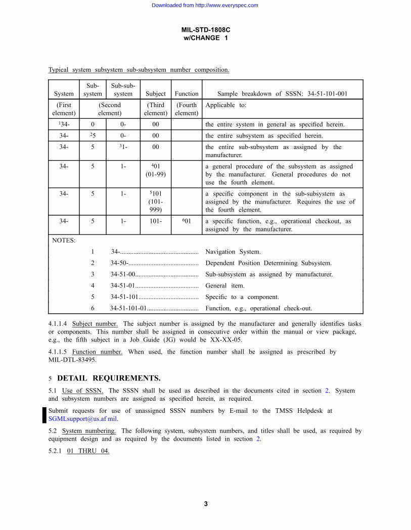
4.1.1 Number composition. The basic SSSN is composed of two- and three-digit elements (see table in step4.1.1.3). The first element (system) and the first digit of the second element (subsystem) are assigned asspecified herein (see section 5). The second digit of the second element (sub-subsystem) and the thirdelement (subject) are assigned by the manufacturer according to the complexity of the equipment andthe numbering application. The fourth element (function) is used when typical maintenance functions arerequired. Depending on program needs, such as supportability analysis, configuration management, work unitcodes, engineering data, etc., additional elements may be added to the right.
4.1.1.1 System number. When assigning system or subsystem numbers to information applicable to a wholesystem or whole subsystem zeros shall occupy the applicable elements and digits of the SSSN. For example,Information about the complete Navigation system located in an On-equipment Maintenance Manual Set(OMMS), General System (GS) manual would be assigned the SSSN 34-00-00. Information containedin this manual must be applicable to the entire Navigation system.
4.1.1.2 Subsystem number. Continuing the example in 4.1.1.1, if subsystems are so complex that theinformation cannot be practically covered, additional subsystem breakouts may be required. The informationin these manuals would be confined to the specific subsystem, e.g., information for the Dependent PositionDetermining subsystem would be assigned 34-50-00.
4.1.1.3 Sub-subsystem number. Systems designed with very complex subsystems may require furtherbreakout into sub-subsystems. The sub-subsystem element numbers and descriptions are defined by themanufacturer. Sub-subsystems shall be indicated by a number greater than zero in the second element,second digit, e.g., 34-51-00. In this case, -51 represents a sub-subsystem, e.g., Global Positioning System(GPS), of the Dependent Position Determining subsystem (34-50-00) of the Navigation System (34-00-00).
2
Downloaded from http://www.everyspec.com
MIL-STD-1808Cw/CHANGE 1
Typical system subsystem sub-subsystem number composition.
SystemSub-system
Sub-sub-system Subject Function Sample breakdown of SSSN: 34-51-101-001
(Firstelement)
(Secondelement)
(Thirdelement)
(Fourthelement)
Applicable to:
134- 0 0- 00 the entire system in general as specified herein.
34- 25 0- 00 the entire subsystem as specified herein.
34- 5 31- 00 the entire sub-subsystem as assigned by themanufacturer.
34- 5 1- 401(01-99)
a general procedure of the subsystem as assignedby the manufacturer. General procedures do notuse the fourth element.
34- 5 1- 5101(101-999)
a specific component in the sub-subsystem asassigned by the manufacturer. Requires the use ofthe fourth element.
34- 5 1- 101- 601 a specific function, e.g., operational checkout, asassigned by the manufacturer.
NOTES:
1 34-............................................... Navigation System.
2 34-50-.......................................... Dependent Position Determining Subsystem.
3 34-51-00...................................... Sub-subsystem as assigned by manufacturer.
4 34-51-01...................................... General item.
5 34-51-101.................................... Specific to a component.
6 34-51-101-01............................... Function, e.g., operational check-out.
4.1.1.4 Subject number. The subject number is assigned by the manufacturer and generally identifies tasksor components. This number shall be assigned in consecutive order within the manual or view package,e.g., the fifth subject in a Job Guide (JG) would be XX-XX-05.
4.1.1.5 Function number. When used, the function number shall be assigned as prescribed byMIL-DTL-83495.
5 DETAIL REQUIREMENTS.5.1 Use of SSSN. The SSSN shall be used as described in the documents cited in section 2. Systemand subsystem numbers are assigned as specified herein, as required.
Submit requests for use of unassigned SSSN numbers by E-mail to the TMSS Helpdesk [email protected] mil.
5.2 System numbering. The following system, subsystem numbers, and titles shall be used, as required byequipment design and as required by the documents listed in section 2.
5.2.1 01 THRU 04.
3
Downloaded from http://www.everyspec.com
MIL-STD-1808Cw/CHANGE 1
SYSTEM SUB-SYSTEM TITLE DEFINITION
01THRU04
UNASSIGNED
4
Downloaded from http://www.everyspec.com
MIL-STD-1808Cw/CHANGE 1
SYSTEM SUB-SYSTEM TITLE DEFINITION
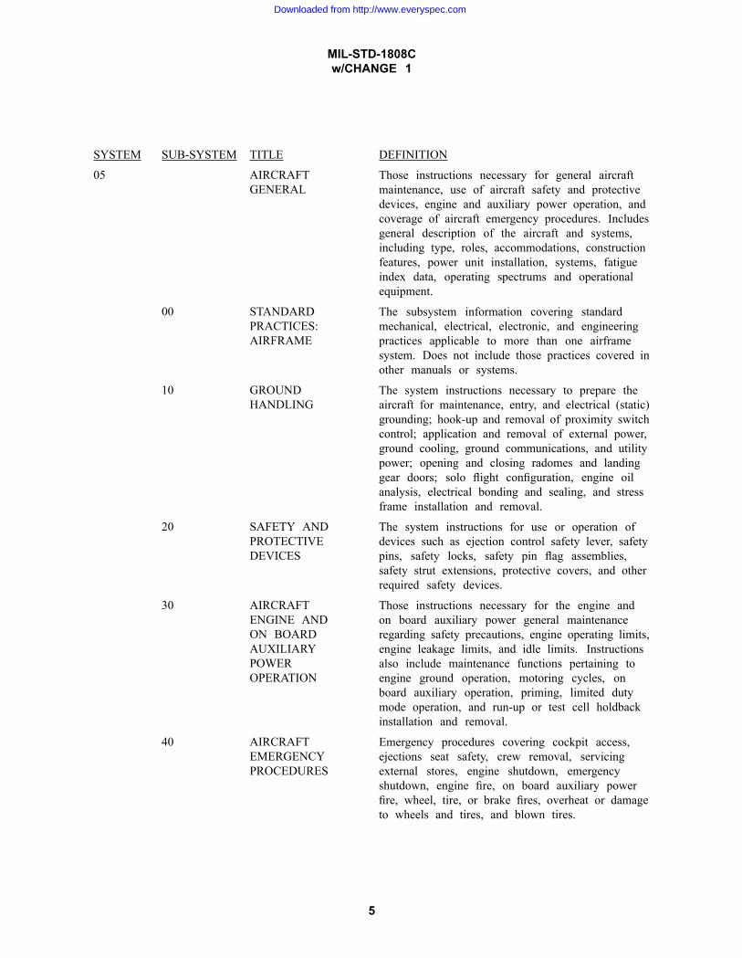
05 AIRCRAFTGENERAL
Those instructions necessary for general aircraftmaintenance, use of aircraft safety and protectivedevices, engine and auxiliary power operation, andcoverage of aircraft emergency procedures. Includesgeneral description of the aircraft and systems,including type, roles, accommodations, constructionfeatures, power unit installation, systems, fatigueindex data, operating spectrums and operationalequipment.
00 STANDARDPRACTICES:AIRFRAME
The subsystem information covering standardmechanical, electrical, electronic, and engineeringpractices applicable to more than one airframesystem. Does not include those practices covered inother manuals or systems.
10 GROUNDHANDLING
The system instructions necessary to prepare theaircraft for maintenance, entry, and electrical (static)grounding; hook-up and removal of proximity switchcontrol; application and removal of external power,ground cooling, ground communications, and utilitypower; opening and closing radomes and landinggear doors; solo flight configuration, engine oilanalysis, electrical bonding and sealing, and stressframe installation and removal.
20 SAFETY ANDPROTECTIVEDEVICES
The system instructions for use or operation ofdevices such as ejection control safety lever, safetypins, safety locks, safety pin flag assemblies,safety strut extensions, protective covers, and otherrequired safety devices.
30 AIRCRAFTENGINE ANDON BOARDAUXILIARYPOWEROPERATION
Those instructions necessary for the engine andon board auxiliary power general maintenanceregarding safety precautions, engine operating limits,engine leakage limits, and idle limits. Instructionsalso include maintenance functions pertaining toengine ground operation, motoring cycles, onboard auxiliary operation, priming, limited dutymode operation, and run-up or test cell holdbackinstallation and removal.
40 AIRCRAFTEMERGENCYPROCEDURES
Emergency procedures covering cockpit access,ejections seat safety, crew removal, servicingexternal stores, engine shutdown, emergencyshutdown, engine fire, on board auxiliary powerfire, wheel, tire, or brake fires, overheat or damageto wheels and tires, and blown tires.
5
Downloaded from http://www.everyspec.com
MIL-STD-1808Cw/CHANGE 1
SYSTEM SUB-SYSTEM TITLE DEFINITION
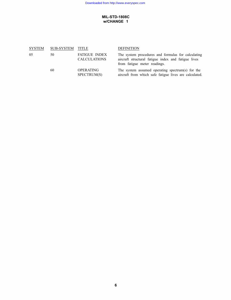
05 50 FATIGUE INDEXCALCULATIONS
The system procedures and formulas for calculatingaircraft structural fatigue index and fatigue livesfrom fatigue meter readings.
60 OPERATINGSPECTRUM(S)
The system assumed operating spectrum(s) for theaircraft from which safe fatigue lives are calculated.
6
Downloaded from http://www.everyspec.com
MIL-STD-1808Cw/CHANGE 1
SYSTEM SUB-SYSTEM TITLE DEFINITION
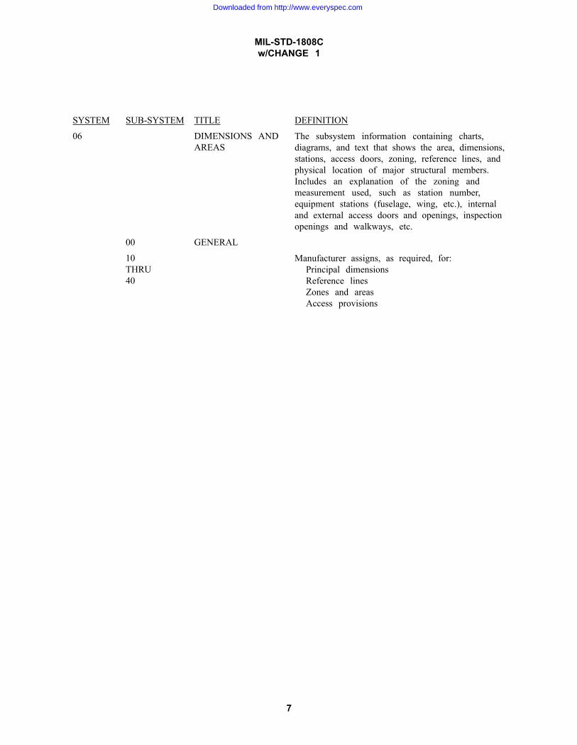
06 DIMENSIONS ANDAREAS
The subsystem information containing charts,diagrams, and text that shows the area, dimensions,stations, access doors, zoning, reference lines, andphysical location of major structural members.Includes an explanation of the zoning andmeasurement used, such as station number,equipment stations (fuselage, wing, etc.), internaland external access doors and openings, inspectionopenings and walkways, etc.
00 GENERAL
10THRU40
Manufacturer assigns, as required, for:Principal dimensionsReference linesZones and areasAccess provisions
7
Downloaded from http://www.everyspec.com
MIL-STD-1808Cw/CHANGE 1
SYSTEM SUB-SYSTEM TITLE DEFINITION
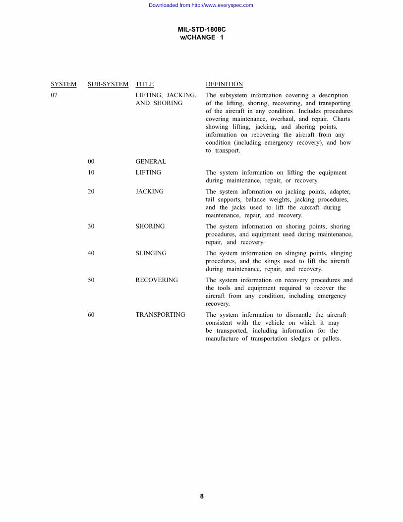
07 LIFTING, JACKING,AND SHORING
The subsystem information covering a descriptionof the lifting, shoring, recovering, and transportingof the aircraft in any condition. Includes procedurescovering maintenance, overhaul, and repair. Chartsshowing lifting, jacking, and shoring points,information on recovering the aircraft from anycondition (including emergency recovery), and howto transport.
00 GENERAL
10 LIFTING The system information on lifting the equipmentduring maintenance, repair, or recovery.
20 JACKING The system information on jacking points, adapter,tail supports, balance weights, jacking procedures,and the jacks used to lift the aircraft duringmaintenance, repair, and recovery.
30 SHORING The system information on shoring points, shoringprocedures, and equipment used during maintenance,repair, and recovery.
40 SLINGING The system information on slinging points, slingingprocedures, and the slings used to lift the aircraftduring maintenance, repair, and recovery.
50 RECOVERING The system information on recovery procedures andthe tools and equipment required to recover theaircraft from any condition, including emergencyrecovery.
60 TRANSPORTING The system information to dismantle the aircraftconsistent with the vehicle on which it maybe transported, including information for themanufacture of transportation sledges or pallets.
8
Downloaded from http://www.everyspec.com
MIL-STD-1808Cw/CHANGE 1
SYSTEM SUB-SYSTEM TITLE DEFINITION
08 LEVELING ANDWEIGHING
The subsystem information necessary to properlylevel the aircraft for any maintenance, overhaulor major repair. Includes units or componentsspecifically dedicated to record, store, or computeweight and balance data. Also includes maintenancepractices necessary to prepare and weigh the aircraft.Includes weight and Center of Gravity (CG) data.This system is used for reference only.Note: See -5 series manuals for actual proceduresfor leveling, weighing and computing CG.
00 GENERAL
10 WEIGHT ANDBALANCE
The system components on the aircraft dedicatedto the specific function of recording, storing, orcomputing weight and balance data.
20 LEVELING The system instructions necessary to prepare theaircraft for leveling and the leveling procedure.Includes information on the leveling equipment.
30 WEIGHING The system instructions necessary to prepare theaircraft for weighing and the weighing procedure.Includes information on the weighing equipmentand limits of variation allowed between physicalrecorded weight and calculated weight based onspecific aircraft records.
40 WEIGHT ANDCG DATA
The system information for weight and momentor index information characteristic of the aircraft,limitations, datum points and lines, CG range,weight and balance management of fuel and otherexpendable loads, residual fuel, ballast, and theeffects of change-of-role. Expression of CG as apercentage of Mean Aerodynamic Chord (MAC).
Includes a diagram of CG envelope and equipmentlocation charts if necessary, affect on the CGposition of dropping or picking up stores (withan example), relevant equipment included in thebasic weight, plus variable equipment, e.g., aircraft"role" or "fit-list" equipment, tabulated, and showingweight, load arm and moment or index of each item.
Also includes the relationship between the aircraftand Engine Control Unit (ECU) datum linesincluding the jet pipe or propeller datum lines andthe effect of an ECU change.
9
Downloaded from http://www.everyspec.com
MIL-STD-1808Cw/CHANGE 1
SYSTEM SUB-SYSTEM TITLE DEFINITION
08 50 STATICSTABILITY
The system information required to determine theminimum nose wheel reaction necessary to ensurethat the aircraft remains stable while being moved,while static during servicing operations, and duringjacking operations.
Includes tabular and graphical data for thecalculation of nose wheel reaction in relation toaircraft mass and residual moment (and wing sweepangles, if appropriate) for both a fully equippedaircraft and for situations where items of equipmentor stores have been removed or the fuel state isoutside the normal sequence.
Includes safety precautions and limitations fordefueling sequences, maximum movement speeds,and movement on gradients or over rough ground.
10
Downloaded from http://www.everyspec.com
MIL-STD-1808Cw/CHANGE 1
SYSTEM SUB-SYSTEM TITLE DEFINITION
09 TOWING ANDTAXIING
The subsystem instructions necessary to tow andtaxi in any condition. Includes instructions andillustrations showing location of attachment points,turning radius, maintenance practices necessary toprepare the aircraft for towing and taxiing, etc.
00 GENERAL
10 TOWING The system instructions to tow, winch, handle, orpush the aircraft in normal or abnormal conditions,such as towing in soft ground, with enginesremoved, aircraft damaged, etc. Includes equipmentand materials required such as towing vehicles, towbars, towing cables, etc.; procedures to be usedsuch as ground turning techniques, use of interphoneand brakes, connection of electrical power, etc.;safety precautions and limitations such as use oflanding gear and control surface locks, minimumturning radius, maximum towing and pushing loadson the landing gear.
20 TAXIING The system instructions to taxi the aircraft innormal or abnormal conditions such as adverseweather conditions. Includes procedures to beused such as use of engines, interphone, brakes,ground turning techniques; safety precautions andlimitations such as jet intake and exhaust dangerareas, minimum turning radius, friction coefficientsfor various ground conditions.
11
Downloaded from http://www.everyspec.com
MIL-STD-1808Cw/CHANGE 1
SYSTEM SUB-SYSTEM TITLE DEFINITION
10 PARKING ANDMOORING
The subsystem instructions to park and moor theaircraft in any condition. Charts showing locationof landing gear and control surface locks, blankingplugs and covers, mooring points, etc., are included.Covers maintenance practices necessary to preparethe aircraft for parking and mooring.
00 GENERAL
10 PARKING The system instructions necessary to park and storethe aircraft in normal and abnormal conditionssuch as with removed engines, damaged aircraft,short or long term exposure in extreme weatherconditions, etc. Includes equipment and materialsrequired such as landing gear and control surfacelocks, wheel chocks, blanking plugs and covers, andcocooning materials; procedures such as periodicengine running, control or drainage of fluid systems,static grounding, etc.; precautions and limitationssuch as landing gear strut pressures, wheel rotation,and control of lifted equipment.
20 MOORING The system instructions necessary to moor orpicket the aircraft in normal or abnormal conditionssuch as with removed engines, damaged aircraft,short or long terms in extreme weather conditions.Includes equipment and materials required such aswheel chocks, mooring blocks, mooring cables,etc.; ballasting and precautions, and limitations forcontrol in high wind conditions.
12
Downloaded from http://www.everyspec.com
MIL-STD-1808Cw/CHANGE 1
SYSTEM SUB-SYSTEM TITLE DEFINITION
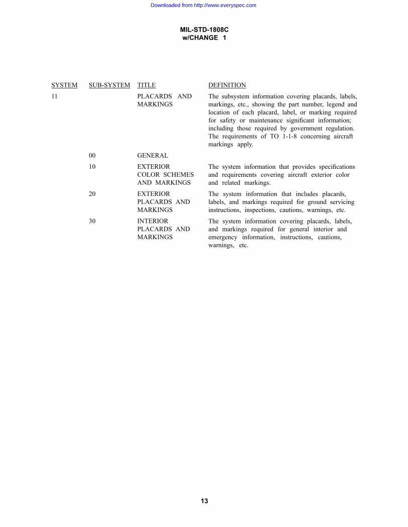
11 PLACARDS ANDMARKINGS
The subsystem information covering placards, labels,markings, etc., showing the part number, legend andlocation of each placard, label, or marking requiredfor safety or maintenance significant information;including those required by government regulation.The requirements of TO 1-1-8 concerning aircraftmarkings apply.
00 GENERAL
10 EXTERIORCOLOR SCHEMESAND MARKINGS
The system information that provides specificationsand requirements covering aircraft exterior colorand related markings.
20 EXTERIORPLACARDS ANDMARKINGS
The system information that includes placards,labels, and markings required for ground servicinginstructions, inspections, cautions, warnings, etc.
30 INTERIORPLACARDS ANDMARKINGS
The system information covering placards, labels,and markings required for general interior andemergency information, instructions, cautions,warnings, etc.
13
Downloaded from http://www.everyspec.com
MIL-STD-1808Cw/CHANGE 1
SYSTEM SUB-SYSTEM TITLE DEFINITION
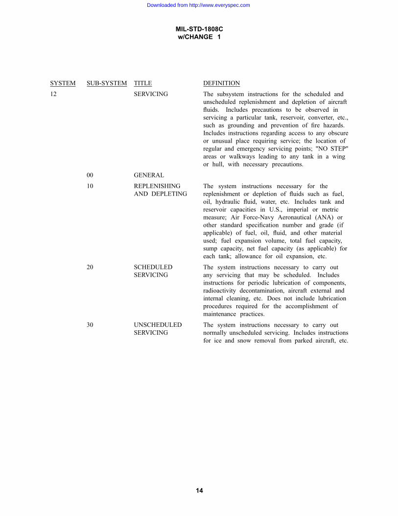
12 SERVICING The subsystem instructions for the scheduled andunscheduled replenishment and depletion of aircraftfluids. Includes precautions to be observed inservicing a particular tank, reservoir, converter, etc.,such as grounding and prevention of fire hazards.Includes instructions regarding access to any obscureor unusual place requiring service; the location ofregular and emergency servicing points; "NO STEP"areas or walkways leading to any tank in a wingor hull, with necessary precautions.
00 GENERAL
10 REPLENISHINGAND DEPLETING
The system instructions necessary for thereplenishment or depletion of fluids such as fuel,oil, hydraulic fluid, water, etc. Includes tank andreservoir capacities in U.S., imperial or metricmeasure; Air Force-Navy Aeronautical (ANA) orother standard specification number and grade (ifapplicable) of fuel, oil, fluid, and other materialused; fuel expansion volume, total fuel capacity,sump capacity, net fuel capacity (as applicable) foreach tank; allowance for oil expansion, etc.
20 SCHEDULEDSERVICING
The system instructions necessary to carry outany servicing that may be scheduled. Includesinstructions for periodic lubrication of components,radioactivity decontamination, aircraft external andinternal cleaning, etc. Does not include lubricationprocedures required for the accomplishment ofmaintenance practices.
30 UNSCHEDULEDSERVICING
The system instructions necessary to carry outnormally unscheduled servicing. Includes instructionsfor ice and snow removal from parked aircraft, etc.
14
Downloaded from http://www.everyspec.com
MIL-STD-1808Cw/CHANGE 1
SYSTEM SUB-SYSTEM TITLE DEFINITION
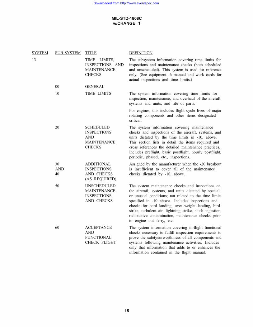
13 TIME LIMITS,INSPECTIONS, ANDMAINTENANCECHECKS
The subsystem information covering time limits forinspections and maintenance checks (both scheduledand unscheduled). This system is used for referenceonly. (See equipment -6 manual and work cards foractual inspections and time limits.)
00 GENERAL
10 TIME LIMITS The system information covering time limits forinspection, maintenance, and overhaul of the aircraft,systems and units, and life of parts.
For engines, this includes flight cycle lives of majorrotating components and other items designatedcritical.
20 SCHEDULEDINSPECTIONSANDMAINTENANCECHECKS
The system information covering maintenancechecks and inspections of the aircraft, systems, andunits dictated by the time limits in -10, above.This section lists in detail the items required andcross references the detailed maintenance practices.Includes preflight, basic postflight, hourly postflight,periodic, phased, etc., inspections.
30AND40
ADDITIONALINSPECTIONSAND CHECKS(AS REQUIRED)
Assigned by the manufacturer when the -20 breakoutis insufficient to cover all of the maintenancechecks dictated by -10, above.
50 UNSCHEDULEDMAINTENANCEINSPECTIONSAND CHECKS
The system maintenance checks and inspections onthe aircraft, systems, and units dictated by specialor unusual conditions; not related to the time limitsspecified in -10 above. Includes inspections andchecks for hard landing, over weight landing, birdstrike, turbulent air, lightning strike, slush ingestion,radioactive contamination, maintenance checks priorto engine out ferry, etc.
60 ACCEPTANCEANDFUNCTIONALCHECK FLIGHT
The system information covering in-flight functionalchecks necessary to fulfill inspection requirements toprove the safety/airworthiness of all components andsystems following maintenance activities. Includesonly that information that adds to or enhances theinformation contained in the flight manual.
15
Downloaded from http://www.everyspec.com
MIL-STD-1808Cw/CHANGE 1
SYSTEM SUB-SYSTEM TITLE DEFINITION
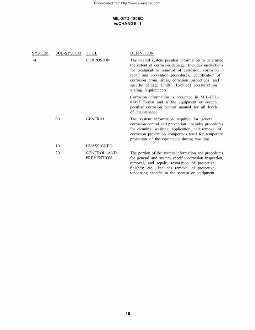
14 CORROSION The overall system peculiar information to determinethe extent of corrosion damage. Includes instructionsfor treatment or removal of corrosion, corrosionrepair and prevention procedures, identification ofcorrosion prone areas, corrosion inspections, andspecific damage limits. Excludes pressurizationsealing requirements.
Corrosion information is presented in MIL-DTL-83495 format and is the equipment or systempeculiar corrosion control manual for all levelsof maintenance.
00 GENERAL The system information required for generalcorrosion control and prevention. Includes proceduresfor cleaning, washing, application, and removal ofcorrosion prevention compounds used for temporaryprotection of the equipment during washing.
10 UNASSIGNED
20 CONTROL ANDPREVENTION
The portion of the system information and proceduresfor general and system specific corrosion inspection,removal, and repair; restoration of protectivefinishes; etc. Includes removal of protectivetopcoating specific to the system or equipment.
16
Downloaded from http://www.everyspec.com
MIL-STD-1808Cw/CHANGE 1
SYSTEM SUB-SYSTEM TITLE DEFINITION
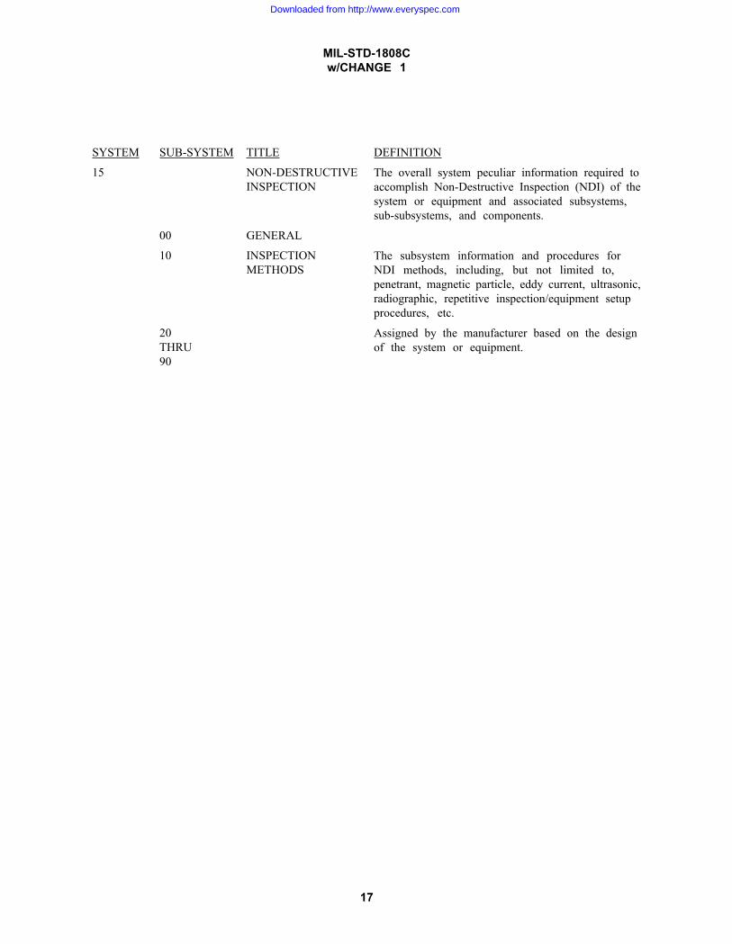
15 NON-DESTRUCTIVEINSPECTION
The overall system peculiar information required toaccomplish Non-Destructive Inspection (NDI) of thesystem or equipment and associated subsystems,sub-subsystems, and components.
00 GENERAL
10 INSPECTIONMETHODS
The subsystem information and procedures forNDI methods, including, but not limited to,penetrant, magnetic particle, eddy current, ultrasonic,radiographic, repetitive inspection/equipment setupprocedures, etc.
20THRU90
Assigned by the manufacturer based on the designof the system or equipment.
17
Downloaded from http://www.everyspec.com
MIL-STD-1808Cw/CHANGE 1
SYSTEM SUB-SYSTEM TITLE DEFINITION
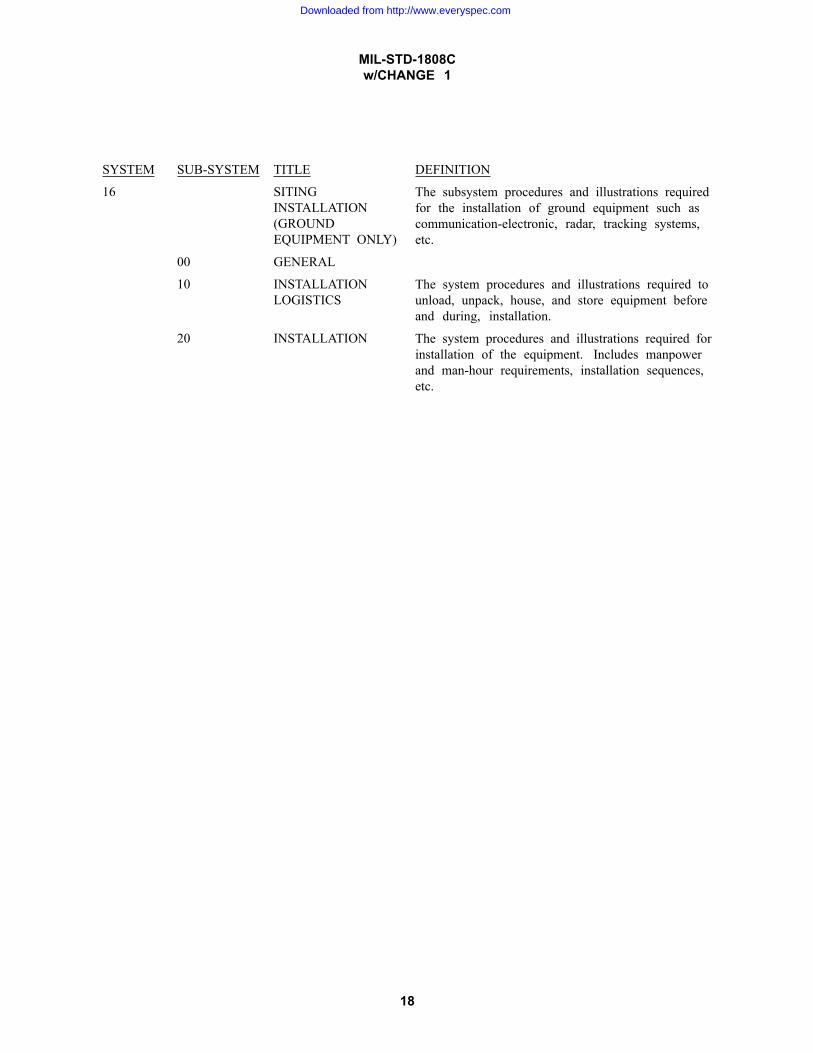
16 SITINGINSTALLATION(GROUNDEQUIPMENT ONLY)
The subsystem procedures and illustrations requiredfor the installation of ground equipment such ascommunication-electronic, radar, tracking systems,etc.
00 GENERAL
10 INSTALLATIONLOGISTICS
The system procedures and illustrations required tounload, unpack, house, and store equipment beforeand during, installation.
20 INSTALLATION The system procedures and illustrations required forinstallation of the equipment. Includes manpowerand man-hour requirements, installation sequences,etc.
18
Downloaded from http://www.everyspec.com
MIL-STD-1808Cw/CHANGE 1
SYSTEM SUB-SYSTEM TITLE DEFINITION
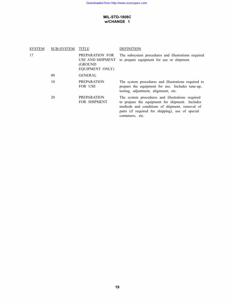
17 PREPARATION FORUSE AND SHIPMENT(GROUNDEQUIPMENT ONLY)
The subsystem procedures and illustrations requiredto prepare equipment for use or shipment.
00 GENERAL
10 PREPARATIONFOR USE
The system procedures and illustrations required toprepare the equipment for use. Includes tune-up,testing, adjustment, alignment, etc.
20 PREPARATIONFOR SHIPMENT
The system procedures and illustrations requiredto prepare the equipment for shipment. Includesmethods and conditions of shipment, removal ofparts (if required for shipping), use of specialcontainers, etc.
19
Downloaded from http://www.everyspec.com
MIL-STD-1808Cw/CHANGE 1
SYSTEM SUB-SYSTEM TITLE DEFINITION
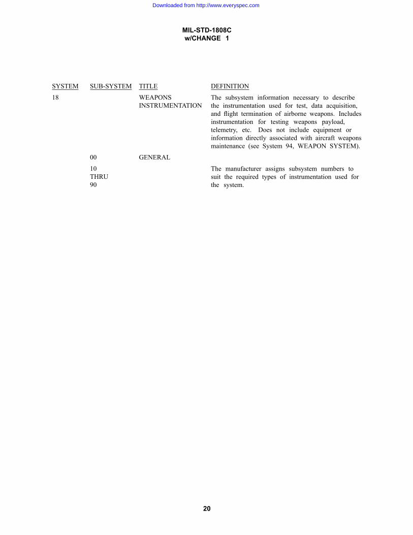
18 WEAPONSINSTRUMENTATION
The subsystem information necessary to describethe instrumentation used for test, data acquisition,and flight termination of airborne weapons. Includesinstrumentation for testing weapons payload,telemetry, etc. Does not include equipment orinformation directly associated with aircraft weaponsmaintenance (see System 94, WEAPON SYSTEM).
00 GENERAL
10THRU90
The manufacturer assigns subsystem numbers tosuit the required types of instrumentation used forthe system.
20
Downloaded from http://www.everyspec.com
MIL-STD-1808Cw/CHANGE 1
SYSTEM SUB-SYSTEM TITLE DEFINITION
19 TRAININGEQUIPMENT
Shall contain that unique equipment required tosupport training systems. Does not include aircraftcomponents, commercial support or test equipment.
00 GENERAL
10THRU90
Subsystems 10 thru 90 shall be used to describeeither individual trainers or groupings of trainers.The manufacturer may assign the subsystem numbersto suit the required types of trainers.
21
Downloaded from http://www.everyspec.com
MIL-STD-1808Cw/CHANGE 1
SYSTEM SUB-SYSTEM TITLE DEFINITION
20 EQUIPMENTSTORAGE
Shall contain those procedures and illustrationsrequired for temporary and extended storage,inspections and treatments during storage, removalfrom storage, etc.
00 GENERAL
10 TEMPORARYSTORAGE
Those instructions necessary to prepare theequipment for temporary storage (under 90 days).Includes special servicing, location of protectivecovers, tie-down points, drains, etc.
20 EXTENDEDSTORAGE
Those instructions necessary to prepare the equipmentfor extended storage (over 90 days). Includesspecial servicing, sealing, venting, protection fromsun, preservatives or protection required, protectivecovers, tie-down points, drains, etc.
30 STORAGEINSPECTIONS ANDTREATMENTS
Those instructions necessary to perform the requiredinspections and apply the required treatments duringstorage.
40 REMOVAL FROMSTORAGE
Those instructions necessary to remove theequipment from storage and prepare it for use.
50 MOVING/FLYINGTO OVERHAUL/MAINTENANCEFACILITY
Those instructions necessary to prepare the equipmentto be moved or flown to an overhaul/maintenancefacility.
22
Downloaded from http://www.everyspec.com
MIL-STD-1808Cw/CHANGE 1
SYSTEM SUB-SYSTEM TITLE DEFINITION
21 AIR CONDITIONING The subsystem components that furnish pressurization,heating, cooling, moisture control, filtering, andtreating of the air used to ventilate the areas ofthe fuselage within the pressure seals. Includescabin supercharger, equipment cooling, heating, fuelsystem heating, expansion turbine, valves, scoops,ducts, etc.
00 GENERAL
10 COMPRESSION The portion of the system and its controls supplyingcompressed air to the cabin. Includes controlsand indicating systems related to the compressors,wiring, etc. Does not include the pressure controland indicating system for the cabin pressurization.
20 DISTRIBUTION The portion of the system used to induct anddistribute air. Includes equipment rack coolingsystems, blowers, scoops, ducting, inlets, checkvalves, wiring, etc. Does not include valves thatare part of pressurization and temperature control.
30 PRESSURIZATIONCONTROL
The portion of the system used to control thepressure within the fuselage. Includes controlvalves, relief valves, indicators, switches, amplifiers,wiring, etc.
40 HEATING The portion of the system and its controls supplyingheated air to the cabin. Includes heater units, fuelsystem and control, ignition, indicating systemsrelated to heater operation, wiring, etc. Does notinclude the temperature control and indicatingsystems.
50 COOLING The portion of the system and its controls supplyingcooled air to the cabin. Includes the cooling unit,indicating systems related to the cooler operation,wiring, etc. Does not include temperature controland indicating systems.
23
Downloaded from http://www.everyspec.com
MIL-STD-1808Cw/CHANGE 1
SYSTEM SUB-SYSTEM TITLE DEFINITION
21 60 TEMPERATURECONTROL
The portion of the system used to control airtemperature within the cabin. Includes controlvalves, thermal sensing devices, switches, indicators,amplifiers, wiring, etc.
70 MOISTURE/AIRCONTAMINANTCONTROL
The portion of the system used to control moisturein the air, to control ozone concentrations, to filterradioactive debris from conditioned air and to treatthe air with deodorizers, insecticides, etc.
80 EQUIPMENTCOOLING
The portion of the system and its controls supplyingcooled air to the equipment. Includes the coolingunit, indicating systems related to the cooleroperation, wiring, etc. Does not include temperaturecontrol and indicating systems.
90 LIQUID COOLING The portion of the system and its controls supplyingcooling liquid to the equipment. Includes thecompressor, coolant pump, indicating systems relatedto the operation, wiring, etc. Does not includetemperature control and indicating systems.
24
Downloaded from http://www.everyspec.com
MIL-STD-1808Cw/CHANGE 1
SYSTEM SUB-SYSTEM TITLE DEFINITION
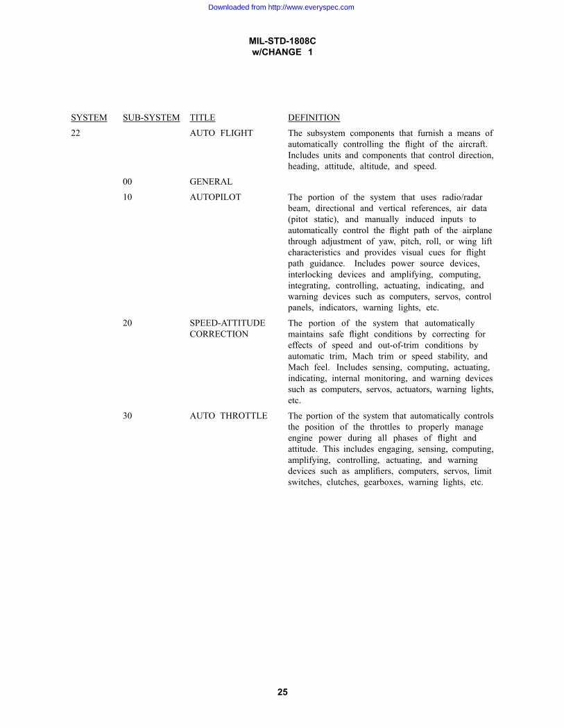
22 AUTO FLIGHT The subsystem components that furnish a means ofautomatically controlling the flight of the aircraft.Includes units and components that control direction,heading, attitude, altitude, and speed.
00 GENERAL
10 AUTOPILOT The portion of the system that uses radio/radarbeam, directional and vertical references, air data(pitot static), and manually induced inputs toautomatically control the flight path of the airplanethrough adjustment of yaw, pitch, roll, or wing liftcharacteristics and provides visual cues for flightpath guidance. Includes power source devices,interlocking devices and amplifying, computing,integrating, controlling, actuating, indicating, andwarning devices such as computers, servos, controlpanels, indicators, warning lights, etc.
20 SPEED-ATTITUDECORRECTION
The portion of the system that automaticallymaintains safe flight conditions by correcting foreffects of speed and out-of-trim conditions byautomatic trim, Mach trim or speed stability, andMach feel. Includes sensing, computing, actuating,indicating, internal monitoring, and warning devicessuch as computers, servos, actuators, warning lights,etc.
30 AUTO THROTTLE The portion of the system that automatically controlsthe position of the throttles to properly manageengine power during all phases of flight andattitude. This includes engaging, sensing, computing,amplifying, controlling, actuating, and warningdevices such as amplifiers, computers, servos, limitswitches, clutches, gearboxes, warning lights, etc.
25
Downloaded from http://www.everyspec.com
MIL-STD-1808Cw/CHANGE 1
SYSTEM SUB-SYSTEM TITLE DEFINITION
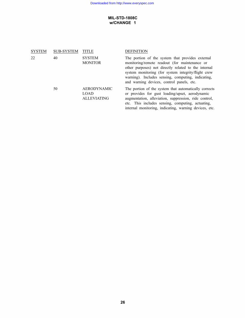
22 40 SYSTEMMONITOR
The portion of the system that provides externalmonitoring/remote readout (for maintenance orother purposes) not directly related to the internalsystem monitoring (for system integrity/flight crewwarning). Includes sensing, computing, indicating,and warning devices, control panels, etc.
50 AERODYNAMICLOADALLEVIATING
The portion of the system that automatically correctsor provides for gust loading/upset, aerodynamicaugmentation, alleviation, suppression, ride control,etc. This includes sensing, computing, actuating,internal monitoring, indicating, warning devices, etc.
26
Downloaded from http://www.everyspec.com
MIL-STD-1808Cw/CHANGE 1
SYSTEM SUB-SYSTEM TITLE DEFINITION
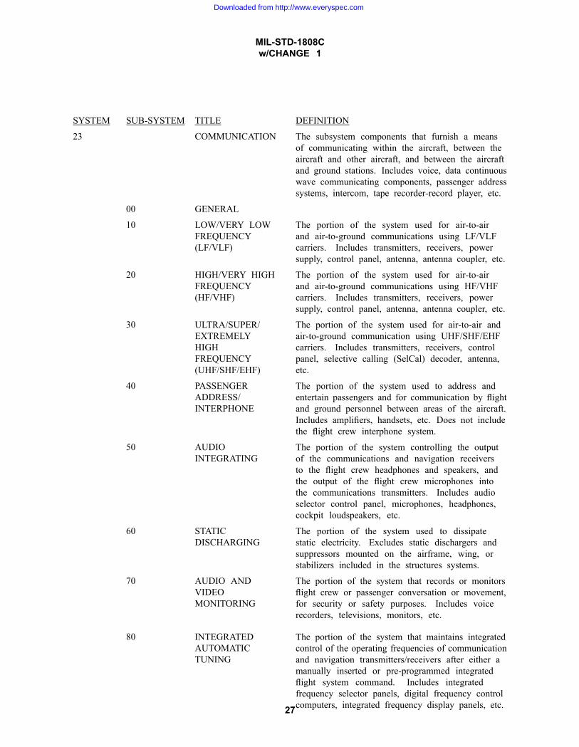
23 COMMUNICATION The subsystem components that furnish a meansof communicating within the aircraft, between theaircraft and other aircraft, and between the aircraftand ground stations. Includes voice, data continuouswave communicating components, passenger addresssystems, intercom, tape recorder-record player, etc.
00 GENERAL
10 LOW/VERY LOWFREQUENCY(LF/VLF)
The portion of the system used for air-to-airand air-to-ground communications using LF/VLFcarriers. Includes transmitters, receivers, powersupply, control panel, antenna, antenna coupler, etc.
20 HIGH/VERY HIGHFREQUENCY(HF/VHF)
The portion of the system used for air-to-airand air-to-ground communications using HF/VHFcarriers. Includes transmitters, receivers, powersupply, control panel, antenna, antenna coupler, etc.
30 ULTRA/SUPER/EXTREMELYHIGHFREQUENCY(UHF/SHF/EHF)
The portion of the system used for air-to-air andair-to-ground communication using UHF/SHF/EHFcarriers. Includes transmitters, receivers, controlpanel, selective calling (SelCal) decoder, antenna,etc.
40 PASSENGERADDRESS/INTERPHONE
The portion of the system used to address andentertain passengers and for communication by flightand ground personnel between areas of the aircraft.Includes amplifiers, handsets, etc. Does not includethe flight crew interphone system.
50 AUDIOINTEGRATING
The portion of the system controlling the outputof the communications and navigation receiversto the flight crew headphones and speakers, andthe output of the flight crew microphones intothe communications transmitters. Includes audioselector control panel, microphones, headphones,cockpit loudspeakers, etc.
60 STATICDISCHARGING
The portion of the system used to dissipatestatic electricity. Excludes static dischargers andsuppressors mounted on the airframe, wing, orstabilizers included in the structures systems.
70 AUDIO ANDVIDEOMONITORING
The portion of the system that records or monitorsflight crew or passenger conversation or movement,for security or safety purposes. Includes voicerecorders, televisions, monitors, etc.
80 INTEGRATEDAUTOMATICTUNING
The portion of the system that maintains integratedcontrol of the operating frequencies of communicationand navigation transmitters/receivers after either amanually inserted or pre-programmed integratedflight system command. Includes integratedfrequency selector panels, digital frequency controlcomputers, integrated frequency display panels, etc.27
Downloaded from http://www.everyspec.com
MIL-STD-1808Cw/CHANGE 1
SYSTEM SUB-SYSTEM TITLE DEFINITION
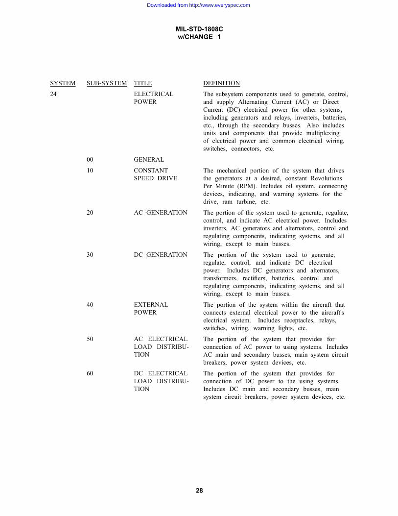
24 ELECTRICALPOWER
The subsystem components used to generate, control,and supply Alternating Current (AC) or DirectCurrent (DC) electrical power for other systems,including generators and relays, inverters, batteries,etc., through the secondary busses. Also includesunits and components that provide multiplexingof electrical power and common electrical wiring,switches, connectors, etc.
00 GENERAL
10 CONSTANTSPEED DRIVE
The mechanical portion of the system that drivesthe generators at a desired, constant RevolutionsPer Minute (RPM). Includes oil system, connectingdevices, indicating, and warning systems for thedrive, ram turbine, etc.
20 AC GENERATION The portion of the system used to generate, regulate,control, and indicate AC electrical power. Includesinverters, AC generators and alternators, control andregulating components, indicating systems, and allwiring, except to main busses.
30 DC GENERATION The portion of the system used to generate,regulate, control, and indicate DC electricalpower. Includes DC generators and alternators,transformers, rectifiers, batteries, control andregulating components, indicating systems, and allwiring, except to main busses.
40 EXTERNALPOWER
The portion of the system within the aircraft thatconnects external electrical power to the aircraft'selectrical system. Includes receptacles, relays,switches, wiring, warning lights, etc.
50 AC ELECTRICALLOAD DISTRIBU-TION
The portion of the system that provides forconnection of AC power to using systems. IncludesAC main and secondary busses, main system circuitbreakers, power system devices, etc.
60 DC ELECTRICALLOAD DISTRIBU-TION
The portion of the system that provides forconnection of DC power to the using systems.Includes DC main and secondary busses, mainsystem circuit breakers, power system devices, etc.
28
Downloaded from http://www.everyspec.com
MIL-STD-1808Cw/CHANGE 1
SYSTEM SUB-SYSTEM TITLE DEFINITION
24 70 ELECTRICALMONITORING ANDPROTECTION
The portion of the system used to supply aircraft orground power for use of the ground power switchingsystem, avionics low cooling protection system,essential 28 VDC bus monitoring system and systemmonitoring. Includes aircraft grounding receptacles.
80 EMERGENCYGENERATION
The portion of the system that provides generationof emergency electrical power in the event ofmain electrical system generator failure or loss ofengine power.
29
Downloaded from http://www.everyspec.com
MIL-STD-1808Cw/CHANGE 1
SYSTEM SUB-SYSTEM TITLE DEFINITION
25 EQUIPMENT/FURNISHINGS
The subsystem items of removable equipment andfurnishings externally mounted on the aircraft orcontained in the flight, passenger, cargo, andaccessory compartments. Includes emergency, buffet,and lavatory equipment. Does not include structuresor equipment assigned specifically to other systems.
00 GENERAL
10 FLIGHTCOMPARTMENT
The portion of the system above the compartmentfloor and between the forward passenger partitionand the forward pressure dome. Includes flightcrew seats, tables, pilot check lists, food containers,curtains, manuals, electronic equipment racks,spare bulbs, fuses, etc. Does not include cargocompartments.
20 PASSENGERCOMPARTMENT
The portion of the system where the passengersare seated. Includes lounges (but not dressingrooms), berths, hat racks, curtains, wall coverings,carpets, magazine racks, movable partitions, walltype thermometers, spare bulbs, fuses, etc.
30 BUFFET/GALLEY The portion of the system where food and beveragesare stored and prepared. Includes removableand fixed cabinets, ovens, refrigerators, garbagecontainers, dish racks, coffee makers and dispensers,containers, electrical outlets, wiring, etc.
40 LAVATORIES The portion of the system containing toilet anddressing room areas with wash basins, dressingtables, and water closet. Includes mirrors, seats,cabinets, dispensing equipment, electrical outlets,wiring, etc. Does not include wash basins and waterclosets covered in System 38, WATER/WASTE.
50 CARGOCOMPARTMENT
The portion of the system used for storage of cargoand the components that are or can be mountedon the aircraft and used to load, unload, restrain,guide, or service cargo. Includes drive systems,rollers, latches, restraint nets, etc.
30
Downloaded from http://www.everyspec.com
MIL-STD-1808Cw/CHANGE 1
SYSTEM SUB-SYSTEM TITLE DEFINITION
25 60 EMERGENCY The portion of the system equipment carried foruse in emergency procedures. Includes evacuationequipment, life rafts, jackets, emergency locatorbeacons, underwater locator devices, first aid kits,incubators, oxygen tents, medical stretchers, landingand signal flares, drag parachutes, evacuationsignaling systems, etc. Does not include fireextinguishers, oxygen equipment, or masks.
70 ACCESSORYCOMPARTMENTS
The portion of the system used for variouscomponents or accessories. Includes wheel wells,tail compartments, hydraulic, electrical, electronic,equipment rack compartments, main batterystructure, etc.
80 INSULATIONAND LINING
The portion of the system used for heat and soundinsulation blankets and those coverings used, eitherwith or without integral insulation, to form theinternal lining of flight, passenger, cargo, accessorycompartments, etc.
90 AERIALDELIVERY
The portion of the system equipment required forcargo or personnel air drop. Includes ContainerDelivery System (CDS) and Air Drop System (ADS)platforms, parachutes and drogue chutes, load releasemechanisms, load transfer devices, anchor cables,static lines, retrieval winches, jump lights, etc.
31
Downloaded from http://www.everyspec.com
MIL-STD-1808Cw/CHANGE 1
SYSTEM SUB-SYSTEM TITLE DEFINITION
26 FIRE PROTECTION The subsystem components, fixed and portable, thatdetect and indicate fire or smoke, and store anddistribute fire extinguishing agents to all protectedareas of the aircraft. Includes bottles, valves,tubing, etc.
00 GENERAL
10 DETECTION The portion of the system used to sense andindicate the presence of overheat, smoke, or fire.
20 EXTINGUISHING The portion of system, fixed or portable, used toextinguish fire.
30 EXPLOSIONSUPPRESSION
The portion of the system used to sense, indicate,and extinguish a flame propagating into a fuelvent or scoop.
32
Downloaded from http://www.everyspec.com
MIL-STD-1808Cw/CHANGE 1
SYSTEM SUB-SYSTEM TITLE DEFINITION
27 FLIGHT CONTROLS The subsystem components that furnish a means ofcontrolling the flight attitude characteristics of theaircraft. Includes hydraulic boost system, rudderpedals, control column linkages, control cables,tab controls, etc. Also includes the functioningand maintenance aspects of the flaps, spoilers, andother control surfaces, but does not include structurecovered structures systems. Does not include rotorcontrols covered in the rotor systems.
00 GENERAL
10 ROLL CONTROL The portion of the system that controls the positionand movement of the ailerons and tabs. Includescontrol wheels, cables, booster, linkages, controlsurfaces, indicators, etc.
20 YAW CONTROL The portion of the system that controls the positionand movement of the rudder and tabs. Includesrudder pedals, tab control wheel, cables, boosters,linkages, control surfaces, position indicators, etc.
30 PITCH CONTROL The portion of the system that controls the positionand movement of the elevator or aileron and tabs.Includes the control column, stick shaker units,automatic stall recovery devices, tab control wheels,cables, boosters, linkages, control surfaces, positionindicators, stall warning systems, etc.
40 HORIZONTALSTABILIZERS
The portion of the system that controls the positionand movement of the horizontal stabilizer/canard.Includes control handle, cables, jackscrews, motors,warning systems, linkages, control surfaces, positionindicators, etc.
50 FLAPS The portion of the system that controls the positionand movement of the trailing edge flaps. Includescontrol handles, cables, actuators, warning systems,linkages, control surfaces, position indicators, etc.
33
Downloaded from http://www.everyspec.com
MIL-STD-1808Cw/CHANGE 1
SYSTEM SUB-SYSTEM TITLE DEFINITION
27 60 SPOILERS, DRAGDEVICES, ANDVARIABLEAERODYNAMICFAIRINGS
The portion of the system that controls the positionand movement of the spoilers, drag devices andvariable aerodynamic fairings. Includes controlhandles, cables, warning systems, linkages, spoilers,drag devices, position indicators, etc.
70 GUST LOCKAND DAMPENER
The portion of the system that protects the controlsurfaces from movement by wind while the aircraftis on the ground. Does not include locking thecontrol by means of flight control boost system.
80 LIFTAUGMENTING
The portion of the system that controls theposition and movement of variable opening wingsslots, leading edge wing flaps and other similarauxiliary devices used for increasing aerodynamiclift. Includes control handles, cables, actuators,linkages, warning systems, control surfaces, positionindicators, etc. Does not include trailing edge flaps.
34
Downloaded from http://www.everyspec.com
MIL-STD-1808Cw/CHANGE 1
SYSTEM SUB-SYSTEM TITLE DEFINITION
28 FUEL The subsystem components that store and deliverfuel to the engine. Includes engine driven fuelpumps (for reciprocating engines), tanks (bladder),valves, boost pumps, etc., and the componentsthat furnish a means of dumping fuel overboard.Includes integral and tip fuel tank leak detection andsealing. Does not include the structure of integralor tip fuel tanks and the fuel cell backing boardscovered in the structures systems. Does not includefuel flow rate sensing, transmitting, and indicating(see System 73, ENGINE FUEL AND CONTROL).
00 GENERAL
10 STORAGE The portion of the system that stores fuel,including external tanks. Includes tank sealing,bladder type cells, ventilating system, cell and tankinter-connectors, over wing filler necks and caps,reservoir feed pumping systems and reservoirs withinthe tanks (not a part of the distribution system), etc.
20 DISTRIBUTION The portion of the system used to distribute fuelfrom the filler connector to the storage system andfrom the storage system to and including the powerplant fuel quick disconnect. Includes plumbing,pumps, valves, controls, etc.
30 DUMP The portion of the system used to dump fueloverboard during flight. Includes plumbing, valves,chutes, controls, etc.
40 INDICATING The portion of the system used to indicate thequantity, temperature, and pressure of the fuel.Includes pressure warning systems for pumpingsystems within the tank, etc. Does not includeengine fuel flow or pressure.
35
Downloaded from http://www.everyspec.com
MIL-STD-1808Cw/CHANGE 1
SYSTEM SUB-SYSTEM TITLE DEFINITION
28
50 IN-FLIGHTREFUELING:RECEIVER
The portion of the system that provides a means ofaccepting in-flight refueling. Includes access doorcontrols, actuators, fuel receptor, distribution systemto fuel storage or interface with standard fueldistribution system, flow controls and indicators,and audio interconnections with the tanker aircraft.Includes manual transfer and refueling controls butexcludes automatic systems based on fuel quantityand Center of Gravity (CG) constraints (see System28-60, FUEL/CG MANAGEMENT).
60 FUEL/CGMANAGEMENT
The portion of the system that controls fueldistribution during aerial and ground refuelingto maintain a safe CG configuration. Uses fuelquantity and stores data to compute aircraft CG.Includes fuel quantity and CG indication for inflightand ground refueling operations.
36
Downloaded from http://www.everyspec.com

MIL-STD-1808Cw/CHANGE 1
SYSTEM SUB-SYSTEM TITLE DEFINITION
29 HYDRAULIC POWER The subsystem components of the system thatfurnish hydraulic fluid under pressure to a commonpoint (manifold) for redistribution to other definedsystems. Includes pumps, regulators, lines, valves,etc.
00 GENERAL
10 MAIN The portion of the system used to store anddeliver hydraulic fluid to using systems. Includestanks, accumulators, valves, pumps, levers, switches,cables, plumbing, wiring, external connectors, etc.Does not include using system supply valves.
20 AUXILIARY The portion of the system classified as auxiliary,emergency, or standby, and used to supplementor take the place of the main hydraulic system.Includes tanks and accumulators separate from themain system, hand pumps, auxiliary pumps, ram airturbine, valves, plumbing, wiring, etc.
30 INDICATION The portion of the system used to indicate thequantity, temperature, and pressure of the hydraulicfluid. Includes transmitters, indicators, wiring,warning systems, etc.
37
Downloaded from http://www.everyspec.com
MIL-STD-1808Cw/CHANGE 1
SYSTEM SUB-SYSTEM TITLE DEFINITION
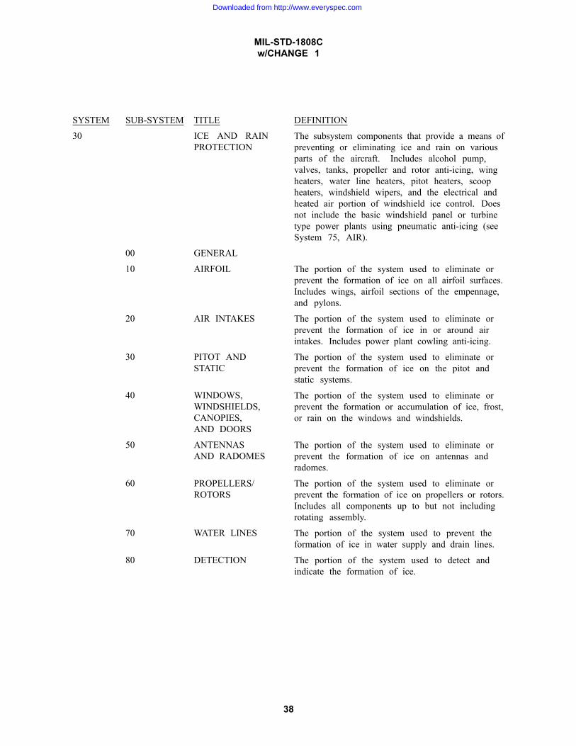
30 ICE AND RAINPROTECTION
The subsystem components that provide a means ofpreventing or eliminating ice and rain on variousparts of the aircraft. Includes alcohol pump,valves, tanks, propeller and rotor anti-icing, wingheaters, water line heaters, pitot heaters, scoopheaters, windshield wipers, and the electrical andheated air portion of windshield ice control. Doesnot include the basic windshield panel or turbinetype power plants using pneumatic anti-icing (seeSystem 75, AIR).
00 GENERAL
10 AIRFOIL The portion of the system used to eliminate orprevent the formation of ice on all airfoil surfaces.Includes wings, airfoil sections of the empennage,and pylons.
20 AIR INTAKES The portion of the system used to eliminate orprevent the formation of ice in or around airintakes. Includes power plant cowling anti-icing.
30 PITOT ANDSTATIC
The portion of the system used to eliminate orprevent the formation of ice on the pitot andstatic systems.
40 WINDOWS,WINDSHIELDS,CANOPIES,AND DOORS
The portion of the system used to eliminate orprevent the formation or accumulation of ice, frost,or rain on the windows and windshields.
50 ANTENNASAND RADOMES
The portion of the system used to eliminate orprevent the formation of ice on antennas andradomes.
60 PROPELLERS/ROTORS
The portion of the system used to eliminate orprevent the formation of ice on propellers or rotors.Includes all components up to but not includingrotating assembly.
70 WATER LINES The portion of the system used to prevent theformation of ice in water supply and drain lines.
80 DETECTION The portion of the system used to detect andindicate the formation of ice.
38
Downloaded from http://www.everyspec.com
MIL-STD-1808Cw/CHANGE 1
SYSTEM SUB-SYSTEM TITLE DEFINITION
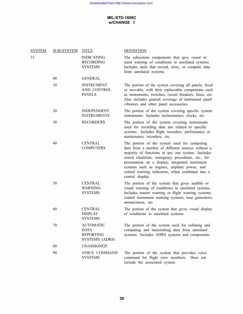
31 INDICATING/RECORDINGSYSTEMS
The subsystem components that give visual oraural warning of conditions in unrelated systems.Includes units that record, store, or compute datafrom unrelated systems.
00 GENERAL
10 INSTRUMENTAND CONTROLPANELS
The portion of the system covering all panels, fixedor movable, with their replaceable components suchas instruments, switches, circuit breakers, fuses, etc.Also includes general coverage of instrument panelvibrators and other panel accessories.
20 INDEPENDENTINSTRUMENTS
The portion of the system covering specific systeminstruments. Includes inclinometers, clocks, etc.
30 RECORDERS The portion of the system covering instrumentsused for recording data not related to specificsystems. Includes flight recorders, performance ormaintenance recorders, etc.
40 CENTRALCOMPUTERS
The portion of the system used for computingdata from a number of different sources without amajority of functions in any one system. Includesstored checklists, emergency procedures, etc., forpresentation on a display, integrated instrumentsystems such as engines, airplane power, andcentral warning indicators, when combined into acentral display.
50 CENTRALWARNINGSYSTEMS
The portion of the system that gives audible orvisual warning of conditions in unrelated systems.Includes master warning or flight warning systems,central instrument warning systems, tone generators,annunciators, etc.
60 CENTRALDISPLAYSYSTEMS
The portion of the system that gives visual displayof conditions in unrelated systems.
70 AUTOMATICDATAREPORTINGSYSTEMS (ADRS)
The portion of the system used for collating andcomputing and transmitting data from unrelatedsystems. Includes ADRS systems and components.
80 UNASSIGNED
90 VOICE COMMANDSYSTEMS
The portion of the system that provides voicecommand for flight crew members. Does notinclude the associated system.
39
Downloaded from http://www.everyspec.com
MIL-STD-1808Cw/CHANGE 1
SYSTEM SUB-SYSTEM TITLE DEFINITION
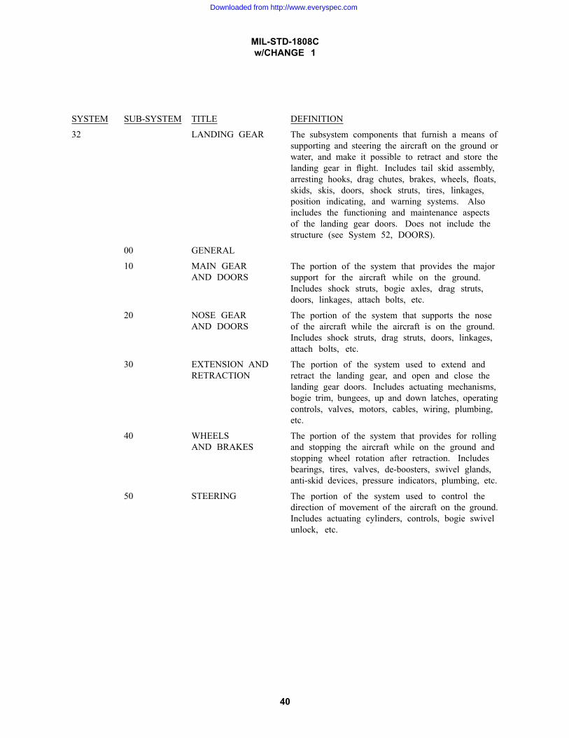
32 LANDING GEAR The subsystem components that furnish a means ofsupporting and steering the aircraft on the ground orwater, and make it possible to retract and store thelanding gear in flight. Includes tail skid assembly,arresting hooks, drag chutes, brakes, wheels, floats,skids, skis, doors, shock struts, tires, linkages,position indicating, and warning systems. Alsoincludes the functioning and maintenance aspectsof the landing gear doors. Does not include thestructure (see System 52, DOORS).
00 GENERAL
10 MAIN GEARAND DOORS
The portion of the system that provides the majorsupport for the aircraft while on the ground.Includes shock struts, bogie axles, drag struts,doors, linkages, attach bolts, etc.
20 NOSE GEARAND DOORS
The portion of the system that supports the noseof the aircraft while the aircraft is on the ground.Includes shock struts, drag struts, doors, linkages,attach bolts, etc.
30 EXTENSION ANDRETRACTION
The portion of the system used to extend andretract the landing gear, and open and close thelanding gear doors. Includes actuating mechanisms,bogie trim, bungees, up and down latches, operatingcontrols, valves, motors, cables, wiring, plumbing,etc.
40 WHEELSAND BRAKES
The portion of the system that provides for rollingand stopping the aircraft while on the ground andstopping wheel rotation after retraction. Includesbearings, tires, valves, de-boosters, swivel glands,anti-skid devices, pressure indicators, plumbing, etc.
50 STEERING The portion of the system used to control thedirection of movement of the aircraft on the ground.Includes actuating cylinders, controls, bogie swivelunlock, etc.
40
Downloaded from http://www.everyspec.com
MIL-STD-1808Cw/CHANGE 1
SYSTEM SUB-SYSTEM TITLE DEFINITION
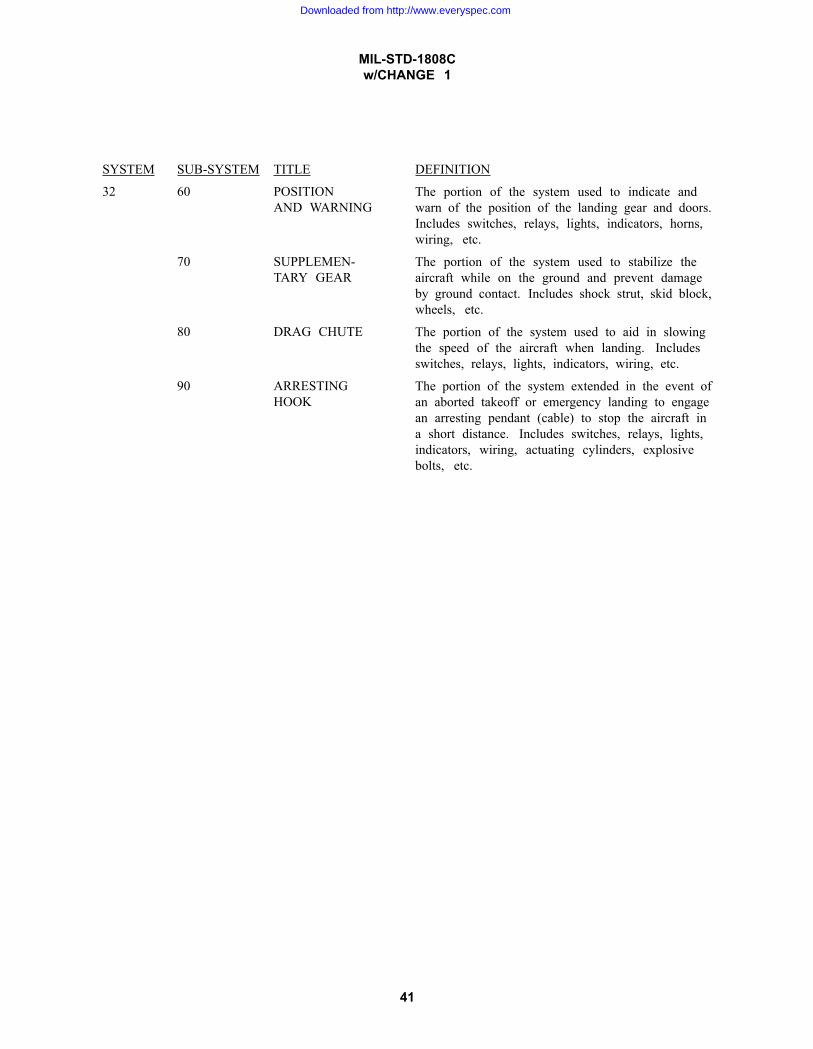
32 60 POSITIONAND WARNING
The portion of the system used to indicate andwarn of the position of the landing gear and doors.Includes switches, relays, lights, indicators, horns,wiring, etc.
70 SUPPLEMEN-TARY GEAR
The portion of the system used to stabilize theaircraft while on the ground and prevent damageby ground contact. Includes shock strut, skid block,wheels, etc.
80 DRAG CHUTE The portion of the system used to aid in slowingthe speed of the aircraft when landing. Includesswitches, relays, lights, indicators, wiring, etc.
90 ARRESTINGHOOK
The portion of the system extended in the event ofan aborted takeoff or emergency landing to engagean arresting pendant (cable) to stop the aircraft ina short distance. Includes switches, relays, lights,indicators, wiring, actuating cylinders, explosivebolts, etc.
41
Downloaded from http://www.everyspec.com
MIL-STD-1808Cw/CHANGE 1
SYSTEM SUB-SYSTEM TITLE DEFINITION
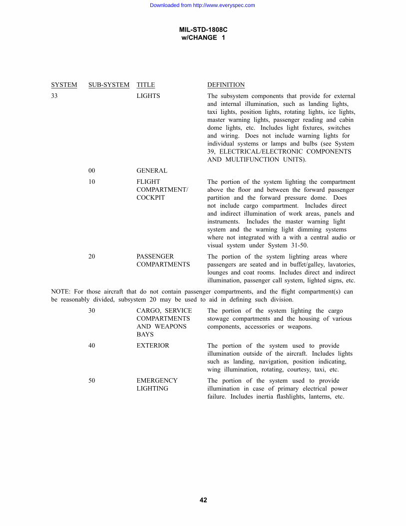
33 LIGHTS The subsystem components that provide for externaland internal illumination, such as landing lights,taxi lights, position lights, rotating lights, ice lights,master warning lights, passenger reading and cabindome lights, etc. Includes light fixtures, switchesand wiring. Does not include warning lights forindividual systems or lamps and bulbs (see System39, ELECTRICAL/ELECTRONIC COMPONENTSAND MULTIFUNCTION UNITS).
00 GENERAL
10 FLIGHTCOMPARTMENT/COCKPIT
The portion of the system lighting the compartmentabove the floor and between the forward passengerpartition and the forward pressure dome. Doesnot include cargo compartment. Includes directand indirect illumination of work areas, panels andinstruments. Includes the master warning lightsystem and the warning light dimming systemswhere not integrated with a with a central audio orvisual system under System 31-50.
20 PASSENGERCOMPARTMENTS
The portion of the system lighting areas wherepassengers are seated and in buffet/galley, lavatories,lounges and coat rooms. Includes direct and indirectillumination, passenger call system, lighted signs, etc.
NOTE: For those aircraft that do not contain passenger compartments, and the flight compartment(s) canbe reasonably divided, subsystem 20 may be used to aid in defining such division.
30 CARGO, SERVICECOMPARTMENTSAND WEAPONSBAYS
The portion of the system lighting the cargostowage compartments and the housing of variouscomponents, accessories or weapons.
40 EXTERIOR The portion of the system used to provideillumination outside of the aircraft. Includes lightssuch as landing, navigation, position indicating,wing illumination, rotating, courtesy, taxi, etc.
50 EMERGENCYLIGHTING
The portion of the system used to provideillumination in case of primary electrical powerfailure. Includes inertia flashlights, lanterns, etc.
42
Downloaded from http://www.everyspec.com
MIL-STD-1808Cw/CHANGE 1
SYSTEM SUB-SYSTEM TITLE DEFINITION
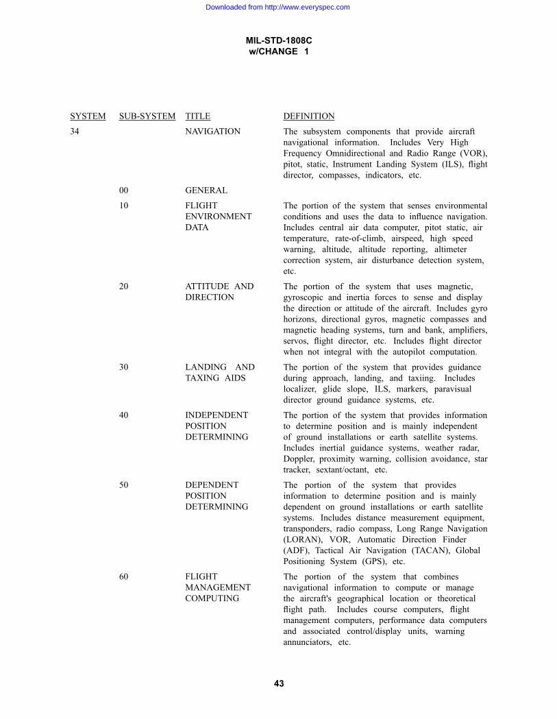
34 NAVIGATION The subsystem components that provide aircraftnavigational information. Includes Very HighFrequency Omnidirectional and Radio Range (VOR),pitot, static, Instrument Landing System (ILS), flightdirector, compasses, indicators, etc.
00 GENERAL
10 FLIGHTENVIRONMENTDATA
The portion of the system that senses environmentalconditions and uses the data to influence navigation.Includes central air data computer, pitot static, airtemperature, rate-of-climb, airspeed, high speedwarning, altitude, altitude reporting, altimetercorrection system, air disturbance detection system,etc.
20 ATTITUDE ANDDIRECTION
The portion of the system that uses magnetic,gyroscopic and inertia forces to sense and displaythe direction or attitude of the aircraft. Includes gyrohorizons, directional gyros, magnetic compasses andmagnetic heading systems, turn and bank, amplifiers,servos, flight director, etc. Includes flight directorwhen not integral with the autopilot computation.
30 LANDING ANDTAXING AIDS
The portion of the system that provides guidanceduring approach, landing, and taxiing. Includeslocalizer, glide slope, ILS, markers, paravisualdirector ground guidance systems, etc.
40 INDEPENDENTPOSITIONDETERMINING
The portion of the system that provides informationto determine position and is mainly independentof ground installations or earth satellite systems.Includes inertial guidance systems, weather radar,Doppler, proximity warning, collision avoidance, startracker, sextant/octant, etc.
50 DEPENDENTPOSITIONDETERMINING
The portion of the system that providesinformation to determine position and is mainlydependent on ground installations or earth satellitesystems. Includes distance measurement equipment,transponders, radio compass, Long Range Navigation(LORAN), VOR, Automatic Direction Finder(ADF), Tactical Air Navigation (TACAN), GlobalPositioning System (GPS), etc.
60 FLIGHTMANAGEMENTCOMPUTING
The portion of the system that combinesnavigational information to compute or managethe aircraft's geographical location or theoreticalflight path. Includes course computers, flightmanagement computers, performance data computersand associated control/display units, warningannunciators, etc.
43
Downloaded from http://www.everyspec.com
MIL-STD-1808Cw/CHANGE 1
SYSTEM SUB-SYSTEM TITLE DEFINITION
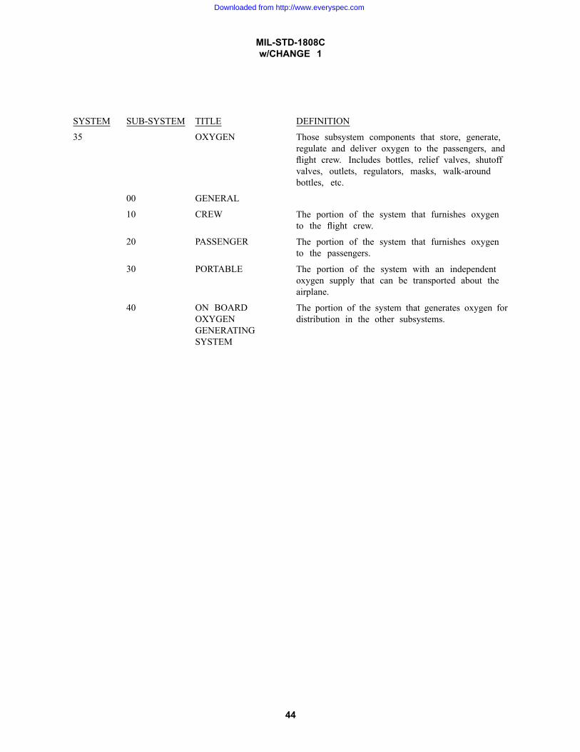
35 OXYGEN Those subsystem components that store, generate,regulate and deliver oxygen to the passengers, andflight crew. Includes bottles, relief valves, shutoffvalves, outlets, regulators, masks, walk-aroundbottles, etc.
00 GENERAL
10 CREW The portion of the system that furnishes oxygento the flight crew.
20 PASSENGER The portion of the system that furnishes oxygento the passengers.
30 PORTABLE The portion of the system with an independentoxygen supply that can be transported about theairplane.
40 ON BOARDOXYGENGENERATINGSYSTEM
The portion of the system that generates oxygen fordistribution in the other subsystems.
44
Downloaded from http://www.everyspec.com
MIL-STD-1808Cw/CHANGE 1
SYSTEM SUB-SYSTEM TITLE DEFINITION
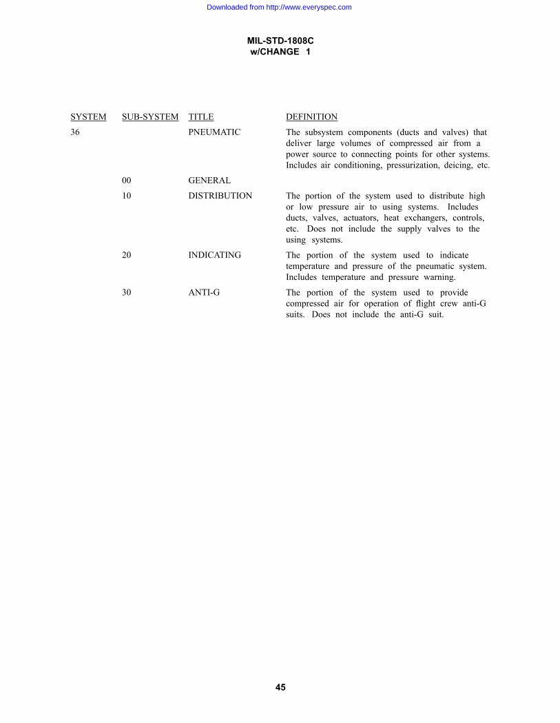
36 PNEUMATIC The subsystem components (ducts and valves) thatdeliver large volumes of compressed air from apower source to connecting points for other systems.Includes air conditioning, pressurization, deicing, etc.
00 GENERAL
10 DISTRIBUTION The portion of the system used to distribute highor low pressure air to using systems. Includesducts, valves, actuators, heat exchangers, controls,etc. Does not include the supply valves to theusing systems.
20 INDICATING The portion of the system used to indicatetemperature and pressure of the pneumatic system.Includes temperature and pressure warning.
30 ANTI-G The portion of the system used to providecompressed air for operation of flight crew anti-Gsuits. Does not include the anti-G suit.
45
Downloaded from http://www.everyspec.com
MIL-STD-1808Cw/CHANGE 1
SYSTEM SUB-SYSTEM TITLE DEFINITION
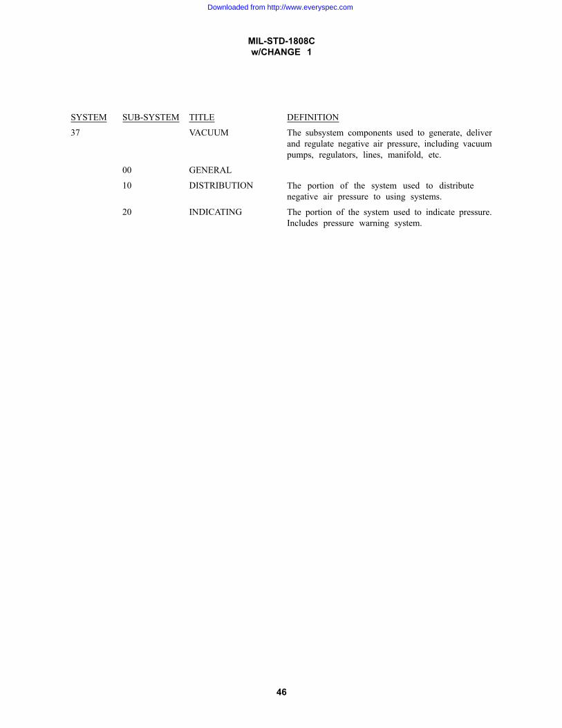
37 VACUUM The subsystem components used to generate, deliverand regulate negative air pressure, including vacuumpumps, regulators, lines, manifold, etc.
00 GENERAL
10 DISTRIBUTION The portion of the system used to distributenegative air pressure to using systems.
20 INDICATING The portion of the system used to indicate pressure.Includes pressure warning system.
46
Downloaded from http://www.everyspec.com
MIL-STD-1808Cw/CHANGE 1
SYSTEM SUB-SYSTEM TITLE DEFINITION
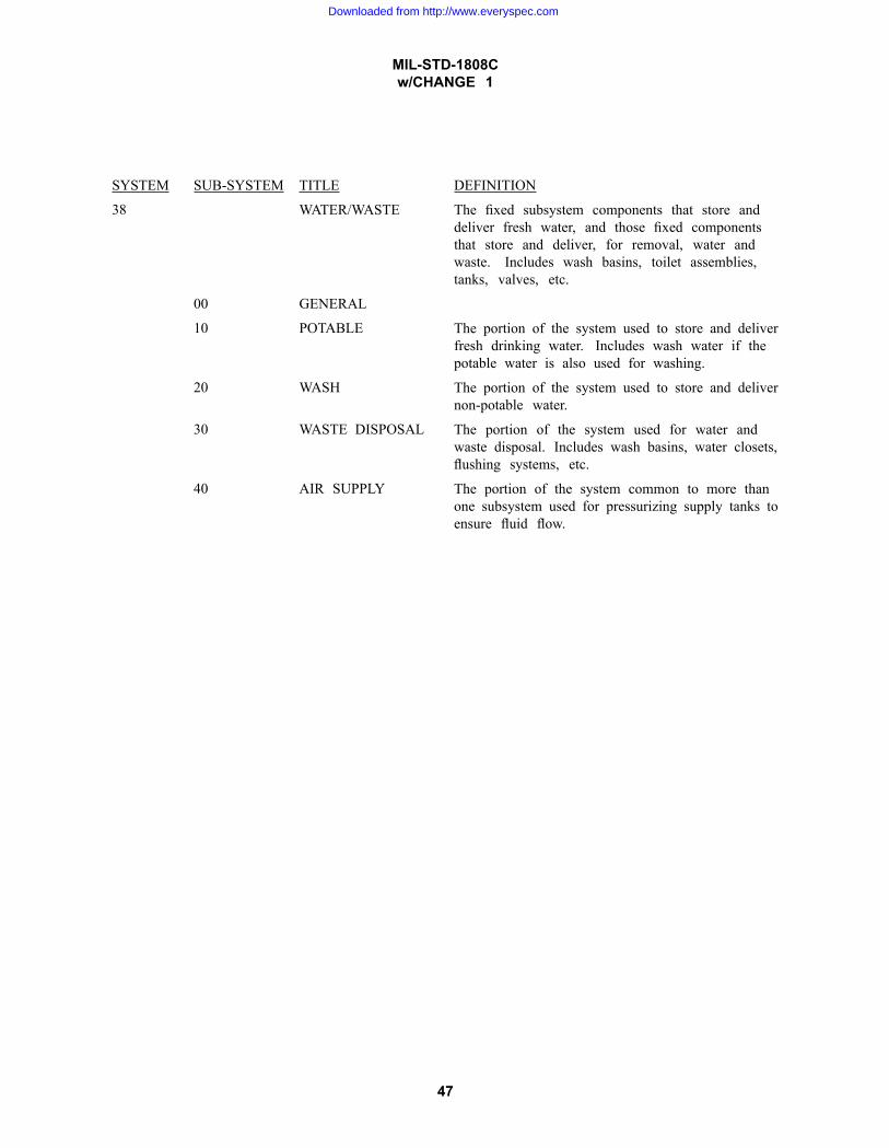
38 WATER/WASTE The fixed subsystem components that store anddeliver fresh water, and those fixed componentsthat store and deliver, for removal, water andwaste. Includes wash basins, toilet assemblies,tanks, valves, etc.
00 GENERAL
10 POTABLE The portion of the system used to store and deliverfresh drinking water. Includes wash water if thepotable water is also used for washing.
20 WASH The portion of the system used to store and delivernon-potable water.
30 WASTE DISPOSAL The portion of the system used for water andwaste disposal. Includes wash basins, water closets,flushing systems, etc.
40 AIR SUPPLY The portion of the system common to more thanone subsystem used for pressurizing supply tanks toensure fluid flow.
47
Downloaded from http://www.everyspec.com
MIL-STD-1808Cw/CHANGE 1
SYSTEM SUB-SYSTEM TITLE DEFINITION
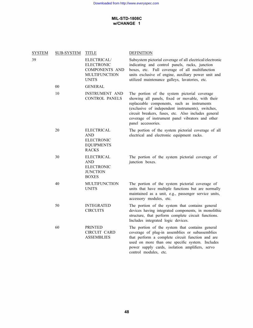
39 ELECTRICAL/ELECTRONICCOMPONENTS ANDMULTIFUNCTIONUNITS
Subsystem pictorial coverage of all electrical/electronicindicating and control panels, racks, junctionboxes, etc. Full coverage of all multifunctionunits exclusive of engine, auxiliary power unit andutilized maintenance galleys, lavatories, etc.
00 GENERAL
10 INSTRUMENT ANDCONTROL PANELS
The portion of the system pictorial coverageshowing all panels, fixed or movable, with theirreplaceable components, such as instruments(exclusive of independent instruments), switches,circuit breakers, fuses, etc. Also includes generalcoverage of instrument panel vibrators and otherpanel accessories.
20 ELECTRICALANDELECTRONICEQUIPMENTSRACKS
The portion of the system pictorial coverage of allelectrical and electronic equipment racks.
30 ELECTRICALANDELECTRONICJUNCTIONBOXES
The portion of the system pictorial coverage ofjunction boxes.
40 MULTIFUNCTIONUNITS
The portion of the system pictorial coverage ofunits that have multiple functions but are normallymaintained as a unit, e.g., passenger service units,accessory modules, etc.
50 INTEGRATEDCIRCUITS
The portion of the system that contains generaldevices having integrated components, in monolithicstructure, that perform complete circuit functions.Includes integrated logic devices.
60 PRINTEDCIRCUIT CARDASSEMBLIES
The portion of the system that contains generalcoverage of plug-in assemblies or subassembliesthat perform a complete circuit function and areused on more than one specific system. Includespower supply cards, isolation amplifiers, servocontrol modules, etc.
48
Downloaded from http://www.everyspec.com
MIL-STD-1808Cw/CHANGE 1
SYSTEM SUB-SYSTEM TITLE DEFINITION
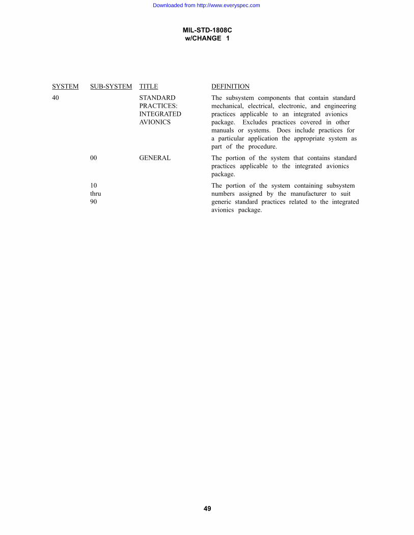
40 STANDARDPRACTICES:INTEGRATEDAVIONICS
The subsystem components that contain standardmechanical, electrical, electronic, and engineeringpractices applicable to an integrated avionicspackage. Excludes practices covered in othermanuals or systems. Does include practices fora particular application the appropriate system aspart of the procedure.
00 GENERAL The portion of the system that contains standardpractices applicable to the integrated avionicspackage.
10thru90
The portion of the system containing subsystemnumbers assigned by the manufacturer to suitgeneric standard practices related to the integratedavionics package.
49
Downloaded from http://www.everyspec.com
MIL-STD-1808Cw/CHANGE 1
SYSTEM SUB-SYSTEM TITLE DEFINITION
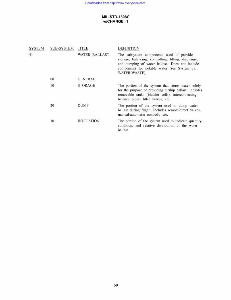
41 WATER BALLAST The subsystem components used to providestorage, balancing, controlling, filling, discharge,and dumping of water ballast. Does not includecomponents for potable water (see System 38,WATER/WASTE).
00 GENERAL
10 STORAGE The portion of the system that stores water solelyfor the purpose of providing airship ballast. Includesremovable tanks (bladder cells), interconnectingbalance pipes, filler valves, etc.
20 DUMP The portion of the system used to dump waterballast during flight. Includes remote/direct valves,manual/automatic controls, etc.
30 INDICATION The portion of the system used to indicate quantity,condition, and relative distribution of the waterballast.
50
Downloaded from http://www.everyspec.com
MIL-STD-1808Cw/CHANGE 1
SYSTEM SUB-SYSTEM TITLE DEFINITION
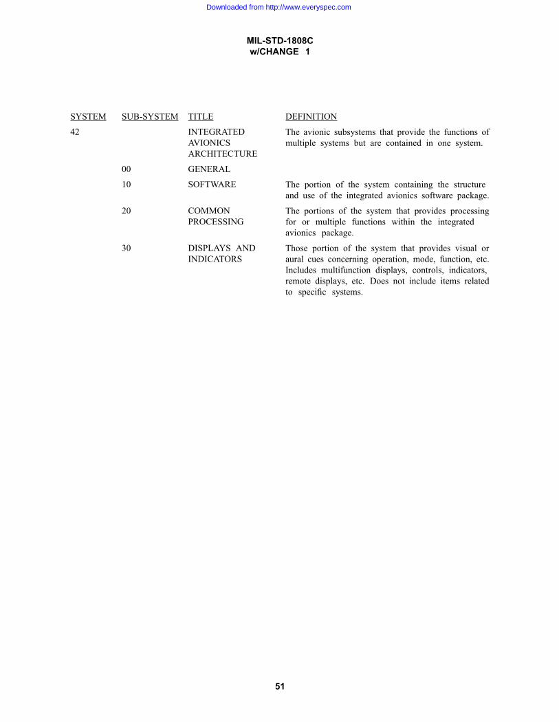
42 INTEGRATEDAVIONICSARCHITECTURE
The avionic subsystems that provide the functions ofmultiple systems but are contained in one system.
00 GENERAL
10 SOFTWARE The portion of the system containing the structureand use of the integrated avionics software package.
20 COMMONPROCESSING
The portions of the system that provides processingfor or multiple functions within the integratedavionics package.
30 DISPLAYS ANDINDICATORS
Those portion of the system that provides visual oraural cues concerning operation, mode, function, etc.Includes multifunction displays, controls, indicators,remote displays, etc. Does not include items relatedto specific systems.
51
Downloaded from http://www.everyspec.com
MIL-STD-1808Cw/CHANGE 1
SYSTEM SUB-SYSTEM TITLE DEFINITION
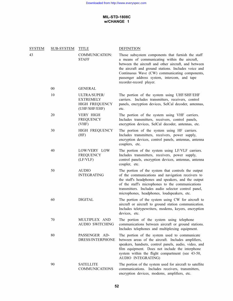
43 COMMUNICATION:STAFF
Those subsystem components that furnish the staffa means of communicating within the aircraft,between the aircraft and other aircraft, and betweenthe aircraft and ground stations. Includes voice andContinuous Wave (CW) communicating components,passenger address system, intercom, and taperecorder-record player.
00 GENERAL
10 ULTRA/SUPER/EXTREMELYHIGH FREQUENCY(UHF/SHF/EHF)
The portion of the system using UHF/SHF/EHFcarriers. Includes transmitters, receivers, controlpanels, encryption devices, SelCal decoder, antennas,etc.
20 VERY HIGHFREQUENCY(VHF)
The portion of the system using VHF carriers.Includes transmitters, receivers, control panels,encryption devices, SelCal decoder, antennas, etc.
30 HIGH FREQUENCY(HF)
The portion of the system using HF carriers.Includes transmitters, receivers, power supply,encryption devices, control panels, antennas, antennacouplers, etc.
40 LOW/VERY LOWFREQUENCY(LF/VLF)
The portion of the system using LF/VLF carriers.Includes transmitters, receivers, power supply,control panels, encryption devices, antennas, antennacoupler, etc.
50 AUDIOINTEGRATING
The portion of the system that controls the outputof the communications and navigation receivers tothe staff's headphones and speakers, and the outputof the staff's microphones to the communicationstransmitters. Includes audio selector control panel,microphones, headphones, loudspeakers, etc.
60 DIGITAL The portion of the system using CW for aircraft toaircraft or aircraft to ground station communication.Includes teletypewriters, modems, keyers, encryptiondevices, etc.
70 MULTIPLEX ANDAUDIO SWITCHING
The portion of the system using telephonecommunications between aircraft or ground stations.Includes telephones and multiplexing equipment.
80 PASSENGER AD-DRESS/INTERPHONE
The portion of the system used to communicatebetween areas of the aircraft. Includes amplifiers,speakers, handsets, control panels, audio, video, andfilm equipment. Does not include the interphonesystem within the flight compartment (see 43-50,AUDIO INTEGRATING)
90 SATELLITECOMMUNICATIONS
The portion of the system used for aircraft to satellitecommunications. Includes receivers, transmitters,encryption devices, modems, amplifiers, etc.
52
Downloaded from http://www.everyspec.com
MIL-STD-1808Cw/CHANGE 1
SYSTEM SUB-SYSTEM TITLE DEFINITION
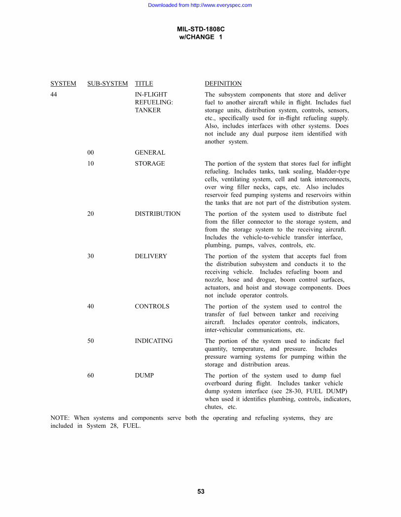
44 IN-FLIGHTREFUELING:TANKER
The subsystem components that store and deliverfuel to another aircraft while in flight. Includes fuelstorage units, distribution system, controls, sensors,etc., specifically used for in-flight refueling supply.Also, includes interfaces with other systems. Doesnot include any dual purpose item identified withanother system.
00 GENERAL
10 STORAGE The portion of the system that stores fuel for inflightrefueling. Includes tanks, tank sealing, bladder-typecells, ventilating system, cell and tank interconnects,over wing filler necks, caps, etc. Also includesreservoir feed pumping systems and reservoirs withinthe tanks that are not part of the distribution system.
20 DISTRIBUTION The portion of the system used to distribute fuelfrom the filler connector to the storage system, andfrom the storage system to the receiving aircraft.Includes the vehicle-to-vehicle transfer interface,plumbing, pumps, valves, controls, etc.
30 DELIVERY The portion of the system that accepts fuel fromthe distribution subsystem and conducts it to thereceiving vehicle. Includes refueling boom andnozzle, hose and drogue, boom control surfaces,actuators, and hoist and stowage components. Doesnot include operator controls.
40 CONTROLS The portion of the system used to control thetransfer of fuel between tanker and receivingaircraft. Includes operator controls, indicators,inter-vehicular communications, etc.
50 INDICATING The portion of the system used to indicate fuelquantity, temperature, and pressure. Includespressure warning systems for pumping within thestorage and distribution areas.
60 DUMP The portion of the system used to dump fueloverboard during flight. Includes tanker vehicledump system interface (see 28-30, FUEL DUMP)when used it identifies plumbing, controls, indicators,chutes, etc.
NOTE: When systems and components serve both the operating and refueling systems, they areincluded in System 28, FUEL.
53
Downloaded from http://www.everyspec.com
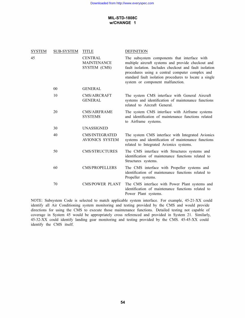
MIL-STD-1808Cw/CHANGE 1
SYSTEM SUB-SYSTEM TITLE DEFINITION
45 CENTRALMAINTENANCESYSTEM (CMS)
The subsystem components that interface withmultiple aircraft systems and provide checkout andfault isolation. Includes checkout and fault isolationprocedures using a central computer complex andstandard fault isolation procedures to locate a singlesystem or component malfunction.
00 GENERAL
10 CMS/AIRCRAFTGENERAL
The system CMS interface with General Aircraftsystems and identification of maintenance functionsrelated to Aircraft General.
20 CMS/AIRFRAMESYSTEMS
The system CMS interface with Airframe systemsand identification of maintenance functions relatedto Airframe systems.
30 UNASSIGNED
40 CMS/INTEGRATEDAVIONICS SYSTEM
The system CMS interface with Integrated Avionicssystems and identification of maintenance functionsrelated to Integrated Avionics systems.
50 CMS/STRUCTURES The CMS interface with Structures systems andidentification of maintenance functions related toStructures systems.
60 CMS/PROPELLERS The CMS interface with Propeller systems andidentification of maintenance functions related toPropeller systems.
70 CMS/POWER PLANT The CMS interface with Power Plant systems andidentification of maintenance functions related toPower Plant systems.
NOTE: Subsystem Code is selected to match applicable system interface. For example, 45-21-XX couldidentify all Air Conditioning system monitoring and testing provided by the CMS and would providedirections for using the CMS to execute those maintenance functions. Detailed testing not capable ofcoverage in System 45 would be appropriately cross referenced and provided in System 21. Similarly,45-32-XX could identify landing gear monitoring and testing provided by the CMS. 45-45-XX couldidentify the CMS itself.
54
Downloaded from http://www.everyspec.com
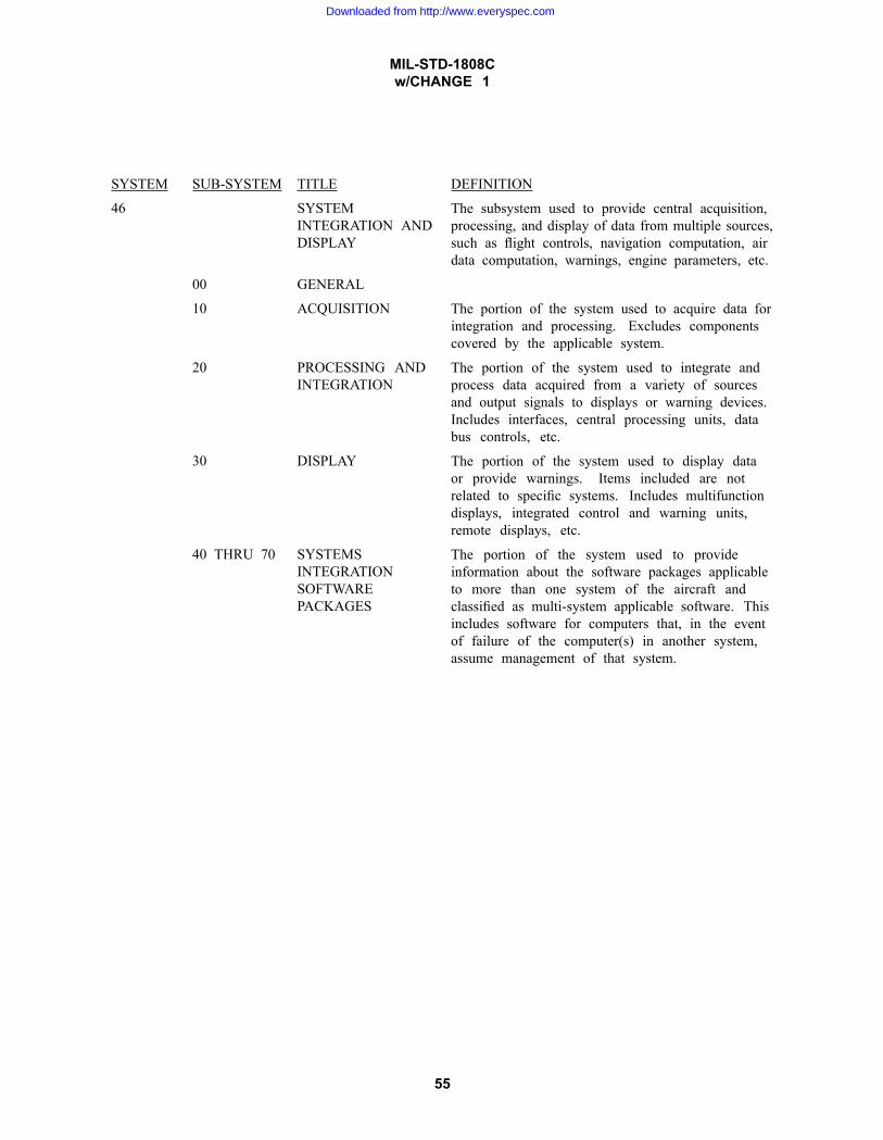
MIL-STD-1808Cw/CHANGE 1
SYSTEM SUB-SYSTEM TITLE DEFINITION
46 SYSTEMINTEGRATION ANDDISPLAY
The subsystem used to provide central acquisition,processing, and display of data from multiple sources,such as flight controls, navigation computation, airdata computation, warnings, engine parameters, etc.
00 GENERAL
10 ACQUISITION The portion of the system used to acquire data forintegration and processing. Excludes componentscovered by the applicable system.
20 PROCESSING ANDINTEGRATION
The portion of the system used to integrate andprocess data acquired from a variety of sourcesand output signals to displays or warning devices.Includes interfaces, central processing units, databus controls, etc.
30 DISPLAY The portion of the system used to display dataor provide warnings. Items included are notrelated to specific systems. Includes multifunctiondisplays, integrated control and warning units,remote displays, etc.
40 THRU 70 SYSTEMSINTEGRATIONSOFTWAREPACKAGES
The portion of the system used to provideinformation about the software packages applicableto more than one system of the aircraft andclassified as multi-system applicable software. Thisincludes software for computers that, in the eventof failure of the computer(s) in another system,assume management of that system.
55
Downloaded from http://www.everyspec.com
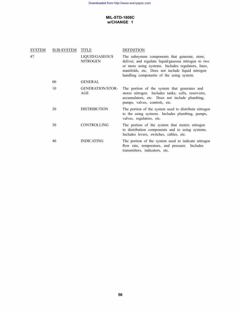
MIL-STD-1808Cw/CHANGE 1
SYSTEM SUB-SYSTEM TITLE DEFINITION
47 LIQUID/GASEOUSNITROGEN
The subsystem components that generate, store,deliver, and regulate liquid/gaseous nitrogen to twoor more using systems. Includes regulators, lines,manifolds, etc. Does not include liquid nitrogenhandling components of the using system.
00 GENERAL
10 GENERATION/STOR-AGE
The portion of the system that generates andstores nitrogen. Includes tanks, cells, reservoirs,accumulators, etc. Does not include plumbing,pumps, valves, controls, etc.
20 DISTRIBUTION The portion of the system used to distribute nitrogento the using systems. Includes plumbing, pumps,valves, regulators, etc.
30 CONTROLLING The portion of the system that meters nitrogento distribution components and to using systems.Includes levers, switches, cables, etc.
40 INDICATING The portion of the system used to indicate nitrogenflow rate, temperature, and pressure. Includestransmitters, indicators, etc.
56
Downloaded from http://www.everyspec.com
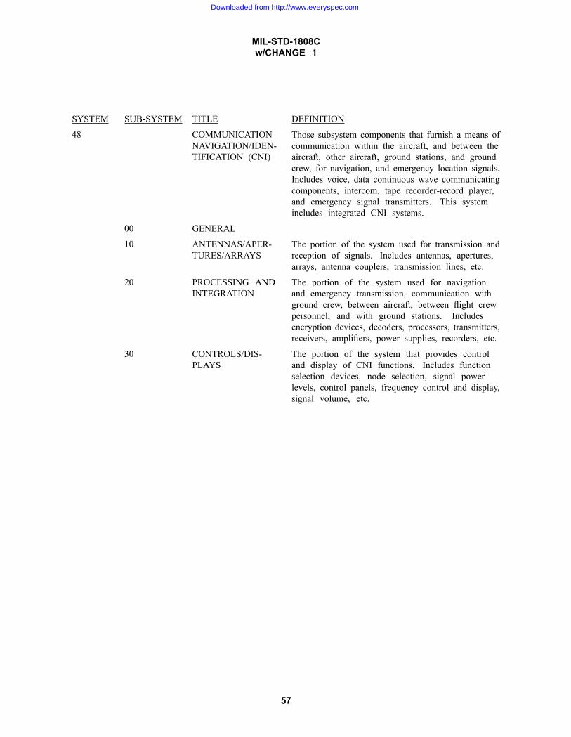
MIL-STD-1808Cw/CHANGE 1
SYSTEM SUB-SYSTEM TITLE DEFINITION
48 COMMUNICATIONNAVIGATION/IDEN-TIFICATION (CNI)
Those subsystem components that furnish a means ofcommunication within the aircraft, and between theaircraft, other aircraft, ground stations, and groundcrew, for navigation, and emergency location signals.Includes voice, data continuous wave communicatingcomponents, intercom, tape recorder-record player,and emergency signal transmitters. This systemincludes integrated CNI systems.
00 GENERAL
10 ANTENNAS/APER-TURES/ARRAYS
The portion of the system used for transmission andreception of signals. Includes antennas, apertures,arrays, antenna couplers, transmission lines, etc.
20 PROCESSING ANDINTEGRATION
The portion of the system used for navigationand emergency transmission, communication withground crew, between aircraft, between flight crewpersonnel, and with ground stations. Includesencryption devices, decoders, processors, transmitters,receivers, amplifiers, power supplies, recorders, etc.
30 CONTROLS/DIS-PLAYS
The portion of the system that provides controland display of CNI functions. Includes functionselection devices, node selection, signal powerlevels, control panels, frequency control and display,signal volume, etc.
57
Downloaded from http://www.everyspec.com
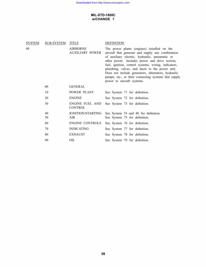
MIL-STD-1808Cw/CHANGE 1
SYSTEM SUB-SYSTEM TITLE DEFINITION
49 AIRBORNEAUXILIARY POWER
The power plants (engines) installed on theaircraft that generate and supply any combinationof auxiliary electric, hydraulic, pneumatic orother power. Includes power and drive section,fuel, ignition, control systems, wiring, indicators,plumbing, valves, and ducts to the power unit.Does not include generators, alternators, hydraulicpumps, etc., or their connecting systems that supplypower to aircraft systems.
00 GENERAL
10 POWER PLANT See System 71 for definition.
20 ENGINE See System 72 for definition.
30 ENGINE FUEL ANDCONTROL
See System 73 for definition.
40 IGNITION/STARTING See System 74 and 80 for definition.50 AIR See System 75 for definition.
60 ENGINE CONTROLS See System 76 for definition.
70 INDICATING See System 77 for definition.
80 EXHAUST See System 78 for definition.
90 OIL See System 79 for definition.
58
Downloaded from http://www.everyspec.com
MIL-STD-1808Cw/CHANGE 1
SYSTEM SUB-SYSTEM TITLE DEFINITION
50 UNASSIGNED
59
Downloaded from http://www.everyspec.com
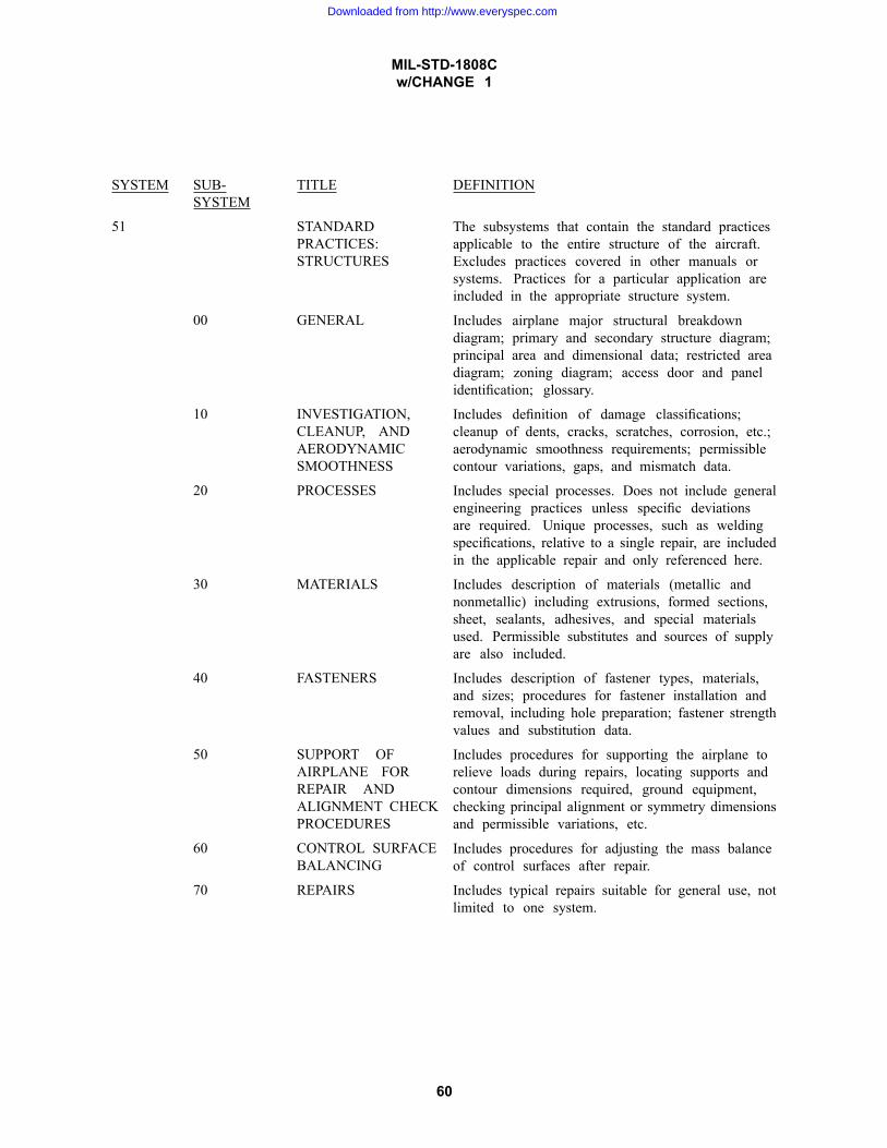
MIL-STD-1808Cw/CHANGE 1
SYSTEM SUB-SYSTEM
TITLE DEFINITION
51 STANDARDPRACTICES:STRUCTURES
The subsystems that contain the standard practicesapplicable to the entire structure of the aircraft.Excludes practices covered in other manuals orsystems. Practices for a particular application areincluded in the appropriate structure system.
00 GENERAL Includes airplane major structural breakdowndiagram; primary and secondary structure diagram;principal area and dimensional data; restricted areadiagram; zoning diagram; access door and panelidentification; glossary.
10 INVESTIGATION,CLEANUP, ANDAERODYNAMICSMOOTHNESS
Includes definition of damage classifications;cleanup of dents, cracks, scratches, corrosion, etc.;aerodynamic smoothness requirements; permissiblecontour variations, gaps, and mismatch data.
20 PROCESSES Includes special processes. Does not include generalengineering practices unless specific deviationsare required. Unique processes, such as weldingspecifications, relative to a single repair, are includedin the applicable repair and only referenced here.
30 MATERIALS Includes description of materials (metallic andnonmetallic) including extrusions, formed sections,sheet, sealants, adhesives, and special materialsused. Permissible substitutes and sources of supplyare also included.
40 FASTENERS Includes description of fastener types, materials,and sizes; procedures for fastener installation andremoval, including hole preparation; fastener strengthvalues and substitution data.
50 SUPPORT OFAIRPLANE FORREPAIR ANDALIGNMENT CHECKPROCEDURES
Includes procedures for supporting the airplane torelieve loads during repairs, locating supports andcontour dimensions required, ground equipment,checking principal alignment or symmetry dimensionsand permissible variations, etc.
60 CONTROL SURFACEBALANCING
Includes procedures for adjusting the mass balanceof control surfaces after repair.
70 REPAIRS Includes typical repairs suitable for general use, notlimited to one system.
60
Downloaded from http://www.everyspec.com
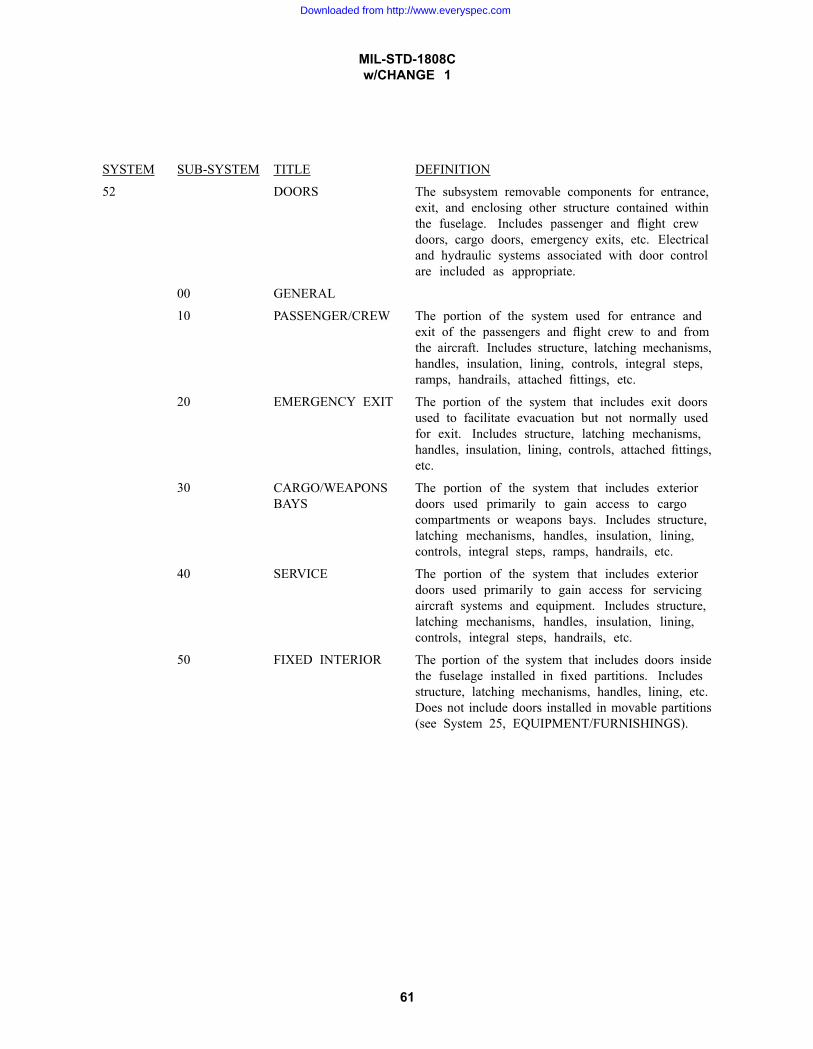
MIL-STD-1808Cw/CHANGE 1
SYSTEM SUB-SYSTEM TITLE DEFINITION
52 DOORS The subsystem removable components for entrance,exit, and enclosing other structure contained withinthe fuselage. Includes passenger and flight crewdoors, cargo doors, emergency exits, etc. Electricaland hydraulic systems associated with door controlare included as appropriate.
00 GENERAL
10 PASSENGER/CREW The portion of the system used for entrance andexit of the passengers and flight crew to and fromthe aircraft. Includes structure, latching mechanisms,handles, insulation, lining, controls, integral steps,ramps, handrails, attached fittings, etc.
20 EMERGENCY EXIT The portion of the system that includes exit doorsused to facilitate evacuation but not normally usedfor exit. Includes structure, latching mechanisms,handles, insulation, lining, controls, attached fittings,etc.
30 CARGO/WEAPONSBAYS
The portion of the system that includes exteriordoors used primarily to gain access to cargocompartments or weapons bays. Includes structure,latching mechanisms, handles, insulation, lining,controls, integral steps, ramps, handrails, etc.
40 SERVICE The portion of the system that includes exteriordoors used primarily to gain access for servicingaircraft systems and equipment. Includes structure,latching mechanisms, handles, insulation, lining,controls, integral steps, handrails, etc.
50 FIXED INTERIOR The portion of the system that includes doors insidethe fuselage installed in fixed partitions. Includesstructure, latching mechanisms, handles, lining, etc.Does not include doors installed in movable partitions(see System 25, EQUIPMENT/FURNISHINGS).
61
Downloaded from http://www.everyspec.com
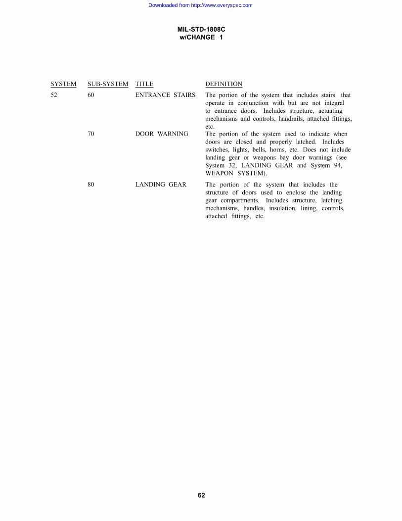
MIL-STD-1808Cw/CHANGE 1
SYSTEM SUB-SYSTEM TITLE DEFINITION
52 60 ENTRANCE STAIRS The portion of the system that includes stairs. thatoperate in conjunction with but are not integralto entrance doors. Includes structure, actuatingmechanisms and controls, handrails, attached fittings,etc.
70 DOOR WARNING The portion of the system used to indicate whendoors are closed and properly latched. Includesswitches, lights, bells, horns, etc. Does not includelanding gear or weapons bay door warnings (seeSystem 32, LANDING GEAR and System 94,WEAPON SYSTEM).
80 LANDING GEAR The portion of the system that includes thestructure of doors used to enclose the landinggear compartments. Includes structure, latchingmechanisms, handles, insulation, lining, controls,attached fittings, etc.
62
Downloaded from http://www.everyspec.com
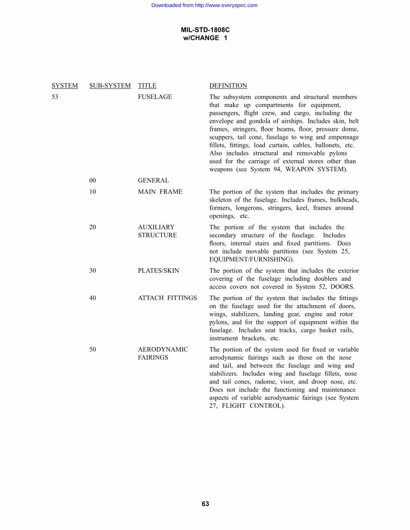
MIL-STD-1808Cw/CHANGE 1
SYSTEM SUB-SYSTEM TITLE DEFINITION
53 FUSELAGE The subsystem components and structural membersthat make up compartments for equipment,passengers, flight crew, and cargo, including theenvelope and gondola of airships. Includes skin, beltframes, stringers, floor beams, floor, pressure dome,scuppers, tail cone, fuselage to wing and empennagefillets, fittings, load curtain, cables, ballonets, etc.Also includes structural and removable pylonsused for the carriage of external stores other thanweapons (see System 94, WEAPON SYSTEM).
00 GENERAL
10 MAIN FRAME The portion of the system that includes the primaryskeleton of the fuselage. Includes frames, bulkheads,formers, longerons, stringers, keel, frames aroundopenings, etc.
20 AUXILIARYSTRUCTURE
The portion of the system that includes thesecondary structure of the fuselage. Includesfloors, internal stairs and fixed partitions. Doesnot include movable partitions (see System 25,EQUIPMENT/FURNISHING).
30 PLATES/SKIN The portion of the system that includes the exteriorcovering of the fuselage including doublers andaccess covers not covered in System 52, DOORS.
40 ATTACH FITTINGS The portion of the system that includes the fittingson the fuselage used for the attachment of doors,wings, stabilizers, landing gear, engine and rotorpylons, and for the support of equipment within thefuselage. Includes seat tracks, cargo basket rails,instrument brackets, etc.
50 AERODYNAMICFAIRINGS
The portion of the system used for fixed or variableaerodynamic fairings such as those on the noseand tail, and between the fuselage and wing andstabilizers. Includes wing and fuselage fillets, noseand tail cones, radome, visor, and droop nose, etc.Does not include the functioning and maintenanceaspects of variable aerodynamic fairings (see System27, FLIGHT CONTROL).
63
Downloaded from http://www.everyspec.com
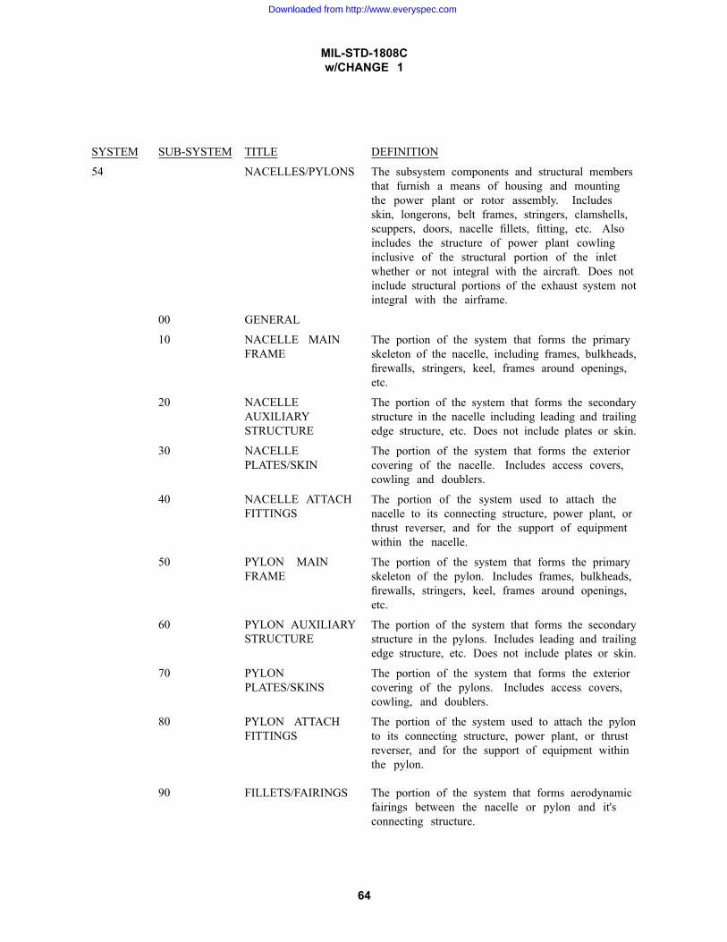
MIL-STD-1808Cw/CHANGE 1
SYSTEM SUB-SYSTEM TITLE DEFINITION
54 NACELLES/PYLONS The subsystem components and structural membersthat furnish a means of housing and mountingthe power plant or rotor assembly. Includesskin, longerons, belt frames, stringers, clamshells,scuppers, doors, nacelle fillets, fitting, etc. Alsoincludes the structure of power plant cowlinginclusive of the structural portion of the inletwhether or not integral with the aircraft. Does notinclude structural portions of the exhaust system notintegral with the airframe.
00 GENERAL
10 NACELLE MAINFRAME
The portion of the system that forms the primaryskeleton of the nacelle, including frames, bulkheads,firewalls, stringers, keel, frames around openings,etc.
20 NACELLEAUXILIARYSTRUCTURE
The portion of the system that forms the secondarystructure in the nacelle including leading and trailingedge structure, etc. Does not include plates or skin.
30 NACELLEPLATES/SKIN
The portion of the system that forms the exteriorcovering of the nacelle. Includes access covers,cowling and doublers.
40 NACELLE ATTACHFITTINGS
The portion of the system used to attach thenacelle to its connecting structure, power plant, orthrust reverser, and for the support of equipmentwithin the nacelle.
50 PYLON MAINFRAME
The portion of the system that forms the primaryskeleton of the pylon. Includes frames, bulkheads,firewalls, stringers, keel, frames around openings,etc.
60 PYLON AUXILIARYSTRUCTURE
The portion of the system that forms the secondarystructure in the pylons. Includes leading and trailingedge structure, etc. Does not include plates or skin.
70 PYLONPLATES/SKINS
The portion of the system that forms the exteriorcovering of the pylons. Includes access covers,cowling, and doublers.
80 PYLON ATTACHFITTINGS
The portion of the system used to attach the pylonto its connecting structure, power plant, or thrustreverser, and for the support of equipment withinthe pylon.
90 FILLETS/FAIRINGS The portion of the system that forms aerodynamicfairings between the nacelle or pylon and it'sconnecting structure.
64
Downloaded from http://www.everyspec.com
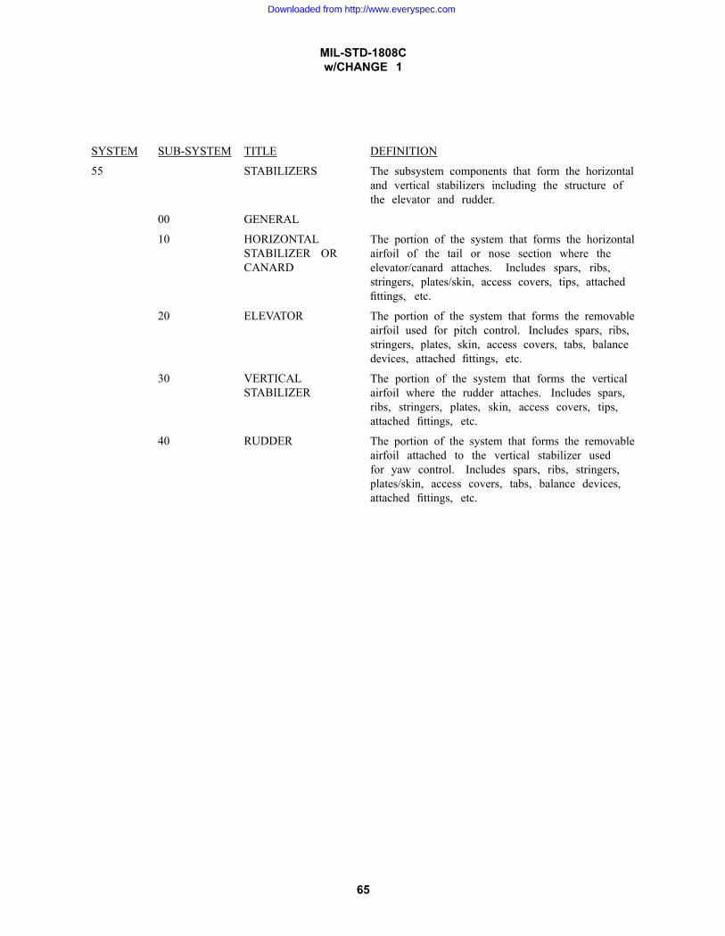
MIL-STD-1808Cw/CHANGE 1
SYSTEM SUB-SYSTEM TITLE DEFINITION
55 STABILIZERS The subsystem components that form the horizontaland vertical stabilizers including the structure ofthe elevator and rudder.
00 GENERAL
10 HORIZONTALSTABILIZER ORCANARD
The portion of the system that forms the horizontalairfoil of the tail or nose section where theelevator/canard attaches. Includes spars, ribs,stringers, plates/skin, access covers, tips, attachedfittings, etc.
20 ELEVATOR The portion of the system that forms the removableairfoil used for pitch control. Includes spars, ribs,stringers, plates, skin, access covers, tabs, balancedevices, attached fittings, etc.
30 VERTICALSTABILIZER
The portion of the system that forms the verticalairfoil where the rudder attaches. Includes spars,ribs, stringers, plates, skin, access covers, tips,attached fittings, etc.
40 RUDDER The portion of the system that forms the removableairfoil attached to the vertical stabilizer usedfor yaw control. Includes spars, ribs, stringers,plates/skin, access covers, tabs, balance devices,attached fittings, etc.
65
Downloaded from http://www.everyspec.com
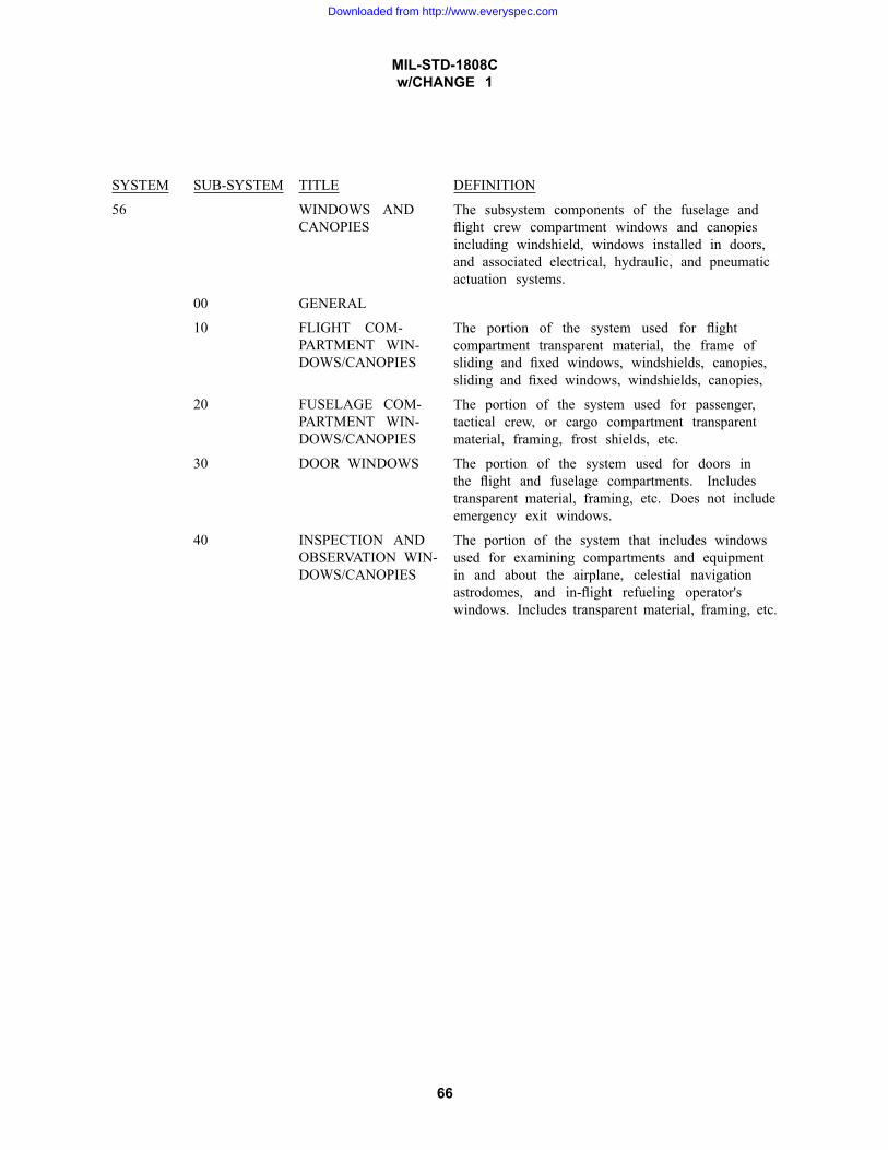
MIL-STD-1808Cw/CHANGE 1
SYSTEM SUB-SYSTEM TITLE DEFINITION
56 WINDOWS ANDCANOPIES
The subsystem components of the fuselage andflight crew compartment windows and canopiesincluding windshield, windows installed in doors,and associated electrical, hydraulic, and pneumaticactuation systems.
00 GENERAL
10 FLIGHT COM-PARTMENT WIN-DOWS/CANOPIES
The portion of the system used for flightcompartment transparent material, the frame ofsliding and fixed windows, windshields, canopies,sliding and fixed windows, windshields, canopies,
20 FUSELAGE COM-PARTMENT WIN-DOWS/CANOPIES
The portion of the system used for passenger,tactical crew, or cargo compartment transparentmaterial, framing, frost shields, etc.
30 DOOR WINDOWS The portion of the system used for doors inthe flight and fuselage compartments. Includestransparent material, framing, etc. Does not includeemergency exit windows.
40 INSPECTION ANDOBSERVATION WIN-DOWS/CANOPIES
The portion of the system that includes windowsused for examining compartments and equipmentin and about the airplane, celestial navigationastrodomes, and in-flight refueling operator'swindows. Includes transparent material, framing, etc.
66
Downloaded from http://www.everyspec.com
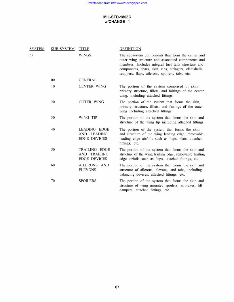
MIL-STD-1808Cw/CHANGE 1
SYSTEM SUB-SYSTEM TITLE DEFINITION
57 WINGS The subsystem components that form the center andouter wing structure and associated components andmembers. Includes integral fuel tank structure andcomponents, spars, skin, ribs, stringers, clamshells,scuppers, flaps, ailerons, spoilers, tabs, etc.
00 GENERAL
10 CENTER WING The portion of the system comprised of skin,primary structure, fillets, and fairings of the centerwing, including attached fittings.
20 OUTER WING The portion of the system that forms the skin,primary structure, fillets, and fairings of the outerwing including attached fittings.
30 WING TIP The portion of the system that forms the skin andstructure of the wing tip including attached fittings.
40 LEADING EDGEAND LEADINGEDGE DEVICES
The portion of the system that forms the skinand structure of the wing leading edge, removableleading edge airfoils such as flaps, slats, attachedfittings, etc.
50 TRAILING EDGEAND TRAILINGEDGE DEVICES
The portion of the system that forms the skin andstructure of the wing trailing edge, removable trailingedge airfoils such as flaps, attached fittings, etc.
60 AILERONS ANDELEVONS
The portion of the system that forms the skin andstructure of ailerons, elevons, and tabs, includingbalancing devices, attached fittings, etc.
70 SPOILERS The portion of the system that forms the skin andstructure of wing mounted spoilers, airbrakes, liftdampers, attached fittings, etc.
67
Downloaded from http://www.everyspec.com

MIL-STD-1808Cw/CHANGE 1
SYSTEM SUB-SYSTEM TITLE DEFINITION
58AND59
UNASSIGNED
68
Downloaded from http://www.everyspec.com

MIL-STD-1808Cw/CHANGE 1
SYSTEM SUB-SYSTEM TITLE DEFINITION
60 STANDARDPRACTICES:PROPELLERS
The subsystems containing the standard mechanicaland electrical and electronic engineering practicesapplicable to more than one propeller or rotorsystem and not covered in Systems 61 thru 69.Does not include those practices covered in othermanuals or systems. Excludes rotor anti-ice system(see System 30, ICE AND RAIN PROTECTION).
00 GENERAL The portion of the system applicable to all propelleror rotor subsystems.
10THRU90
Subsystems 10 thru 90 describe standard practicesand are assigned by the manufacturer to suitgeneric standard practices related to more than onepropeller or rotor system.
69
Downloaded from http://www.everyspec.com
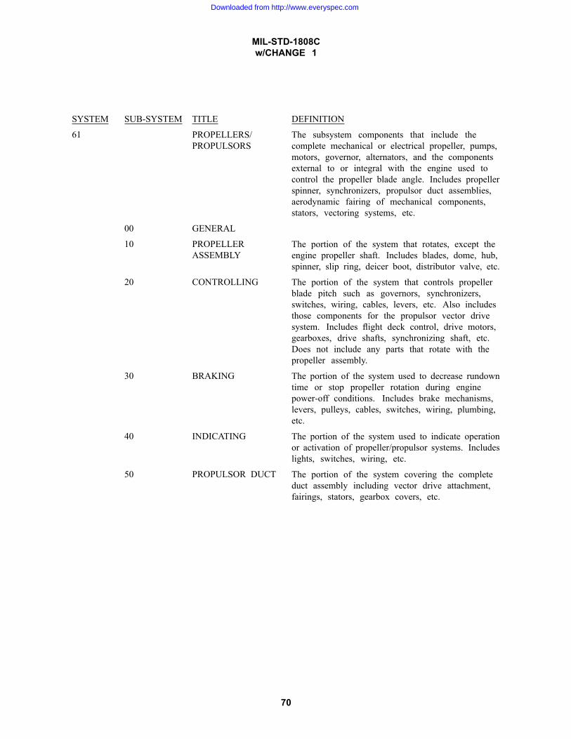
MIL-STD-1808Cw/CHANGE 1
SYSTEM SUB-SYSTEM TITLE DEFINITION
61 PROPELLERS/PROPULSORS
The subsystem components that include thecomplete mechanical or electrical propeller, pumps,motors, governor, alternators, and the componentsexternal to or integral with the engine used tocontrol the propeller blade angle. Includes propellerspinner, synchronizers, propulsor duct assemblies,aerodynamic fairing of mechanical components,stators, vectoring systems, etc.
00 GENERAL
10 PROPELLERASSEMBLY
The portion of the system that rotates, except theengine propeller shaft. Includes blades, dome, hub,spinner, slip ring, deicer boot, distributor valve, etc.
20 CONTROLLING The portion of the system that controls propellerblade pitch such as governors, synchronizers,switches, wiring, cables, levers, etc. Also includesthose components for the propulsor vector drivesystem. Includes flight deck control, drive motors,gearboxes, drive shafts, synchronizing shaft, etc.Does not include any parts that rotate with thepropeller assembly.
30 BRAKING The portion of the system used to decrease rundowntime or stop propeller rotation during enginepower-off conditions. Includes brake mechanisms,levers, pulleys, cables, switches, wiring, plumbing,etc.
40 INDICATING The portion of the system used to indicate operationor activation of propeller/propulsor systems. Includeslights, switches, wiring, etc.
50 PROPULSOR DUCT The portion of the system covering the completeduct assembly including vector drive attachment,fairings, stators, gearbox covers, etc.
70
Downloaded from http://www.everyspec.com
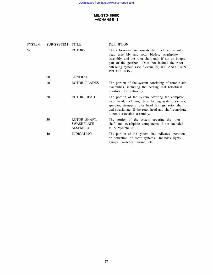
MIL-STD-1808Cw/CHANGE 1
SYSTEM SUB-SYSTEM TITLE DEFINITION
62 ROTORS The subsystem components that include the rotorhead assembly and rotor blades, swashplateassembly, and the rotor shaft unit, if not an integralpart of the gearbox. Does not include the rotoranti-icing system (see System 30, ICE AND RAINPROTECTION).
00 GENERAL
10 ROTOR BLADES The portion of the system consisting of rotor bladeassemblies, including the heating mat (electricalresistors) for anti-icing.
20 ROTOR HEAD The portion of the system covering the completerotor head, including blade folding system, sleeves,spindles, dampers, rotor head fairings, rotor shaft,and swashplate, if the rotor head and shaft constitutea non-dissociable assembly.
30 ROTOR SHAFT/SWASHPLATEASSEMBLY
The portion of the system covering the rotorshaft and swashplate components if not includedin Subsystem 20.
40 INDICATING The portion of the system that indicates operationor activation of rotor systems. Includes lights,gauges, switches, wiring, etc.
71
Downloaded from http://www.everyspec.com
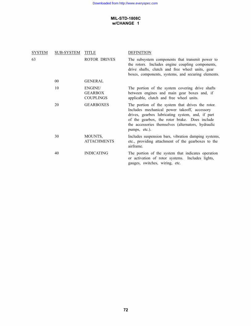
MIL-STD-1808Cw/CHANGE 1
SYSTEM SUB-SYSTEM TITLE DEFINITION
63 ROTOR DRIVES The subsystem components that transmit power tothe rotors. Includes engine coupling components,drive shafts, clutch and free wheel units, gearboxes, components, systems, and securing elements.
00 GENERAL
10 ENGINE/GEARBOXCOUPLINGS
The portion of the system covering drive shaftsbetween engines and main gear boxes and, ifapplicable, clutch and free wheel units.
20 GEARBOXES The portion of the system that drives the rotor.Includes mechanical power takeoff, accessorydrives, gearbox lubricating system, and, if partof the gearbox, the rotor brake. Does includethe accessories themselves (alternators, hydraulicpumps, etc.).
30 MOUNTS,ATTACHMENTS
Includes suspension bars, vibration damping systems,etc., providing attachment of the gearboxes to theairframe.
40 INDICATING The portion of the system that indicates operationor activation of rotor systems. Includes lights,gauges, switches, wiring, etc.
72
Downloaded from http://www.everyspec.com
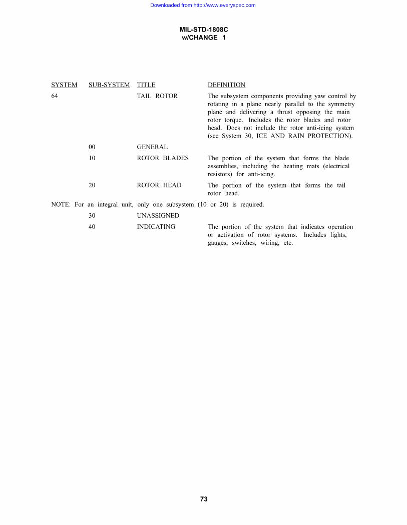
MIL-STD-1808Cw/CHANGE 1
SYSTEM SUB-SYSTEM TITLE DEFINITION
64 TAIL ROTOR The subsystem components providing yaw control byrotating in a plane nearly parallel to the symmetryplane and delivering a thrust opposing the mainrotor torque. Includes the rotor blades and rotorhead. Does not include the rotor anti-icing system(see System 30, ICE AND RAIN PROTECTION).
00 GENERAL
10 ROTOR BLADES The portion of the system that forms the bladeassemblies, including the heating mats (electricalresistors) for anti-icing.
20 ROTOR HEAD The portion of the system that forms the tailrotor head.
NOTE: For an integral unit, only one subsystem (10 or 20) is required.
30 UNASSIGNED
40 INDICATING The portion of the system that indicates operationor activation of rotor systems. Includes lights,gauges, switches, wiring, etc.
73
Downloaded from http://www.everyspec.com
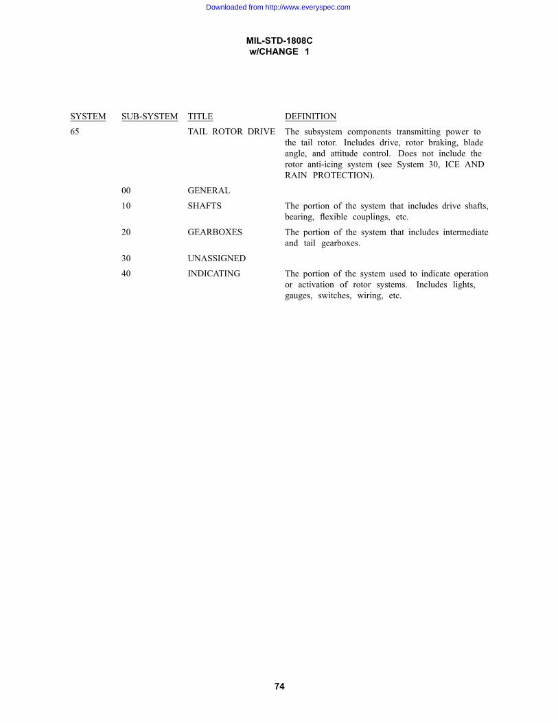
MIL-STD-1808Cw/CHANGE 1
SYSTEM SUB-SYSTEM TITLE DEFINITION
65 TAIL ROTOR DRIVE The subsystem components transmitting power tothe tail rotor. Includes drive, rotor braking, bladeangle, and attitude control. Does not include therotor anti-icing system (see System 30, ICE ANDRAIN PROTECTION).
00 GENERAL
10 SHAFTS The portion of the system that includes drive shafts,bearing, flexible couplings, etc.
20 GEARBOXES The portion of the system that includes intermediateand tail gearboxes.
30 UNASSIGNED
40 INDICATING The portion of the system used to indicate operationor activation of rotor systems. Includes lights,gauges, switches, wiring, etc.
74
Downloaded from http://www.everyspec.com
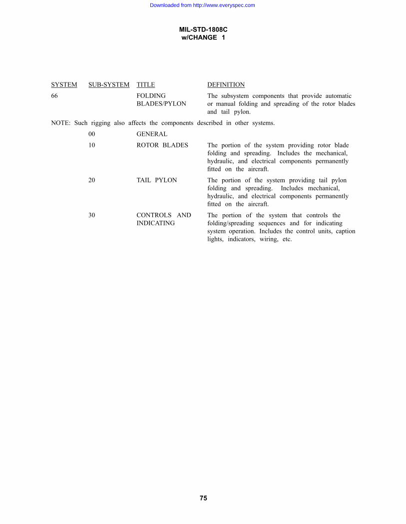
MIL-STD-1808Cw/CHANGE 1
SYSTEM SUB-SYSTEM TITLE DEFINITION
66 FOLDINGBLADES/PYLON
The subsystem components that provide automaticor manual folding and spreading of the rotor bladesand tail pylon.
NOTE: Such rigging also affects the components described in other systems.
00 GENERAL
10 ROTOR BLADES The portion of the system providing rotor bladefolding and spreading. Includes the mechanical,hydraulic, and electrical components permanentlyfitted on the aircraft.
20 TAIL PYLON The portion of the system providing tail pylonfolding and spreading. Includes mechanical,hydraulic, and electrical components permanentlyfitted on the aircraft.
30 CONTROLS ANDINDICATING
The portion of the system that controls thefolding/spreading sequences and for indicatingsystem operation. Includes the control units, captionlights, indicators, wiring, etc.
75
Downloaded from http://www.everyspec.com
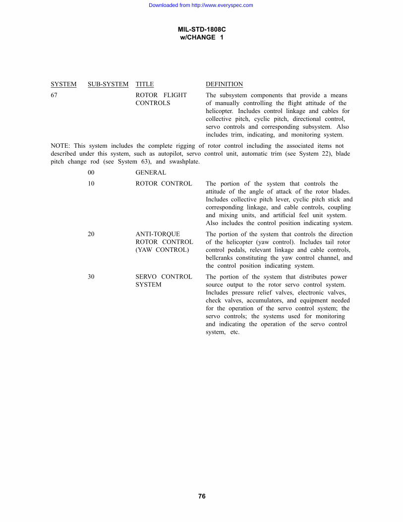
MIL-STD-1808Cw/CHANGE 1
SYSTEM SUB-SYSTEM TITLE DEFINITION
67 ROTOR FLIGHTCONTROLS
The subsystem components that provide a meansof manually controlling the flight attitude of thehelicopter. Includes control linkage and cables forcollective pitch, cyclic pitch, directional control,servo controls and corresponding subsystem. Alsoincludes trim, indicating, and monitoring system.
NOTE: This system includes the complete rigging of rotor control including the associated items notdescribed under this system, such as autopilot, servo control unit, automatic trim (see System 22), bladepitch change rod (see System 63), and swashplate.
00 GENERAL
10 ROTOR CONTROL The portion of the system that controls theattitude of the angle of attack of the rotor blades.Includes collective pitch lever, cyclic pitch stick andcorresponding linkage, and cable controls, couplingand mixing units, and artificial feel unit system.Also includes the control position indicating system.
20 ANTI-TORQUEROTOR CONTROL(YAW CONTROL)
The portion of the system that controls the directionof the helicopter (yaw control). Includes tail rotorcontrol pedals, relevant linkage and cable controls,bellcranks constituting the yaw control channel, andthe control position indicating system.
30 SERVO CONTROLSYSTEM
The portion of the system that distributes powersource output to the rotor servo control system.Includes pressure relief valves, electronic valves,check valves, accumulators, and equipment neededfor the operation of the servo control system; theservo controls; the systems used for monitoringand indicating the operation of the servo controlsystem, etc.
76
Downloaded from http://www.everyspec.com
MIL-STD-1808Cw/CHANGE 1
SYSTEM SUB-SYSTEM TITLE DEFINITION
68AND69
UNASSIGNED
77
Downloaded from http://www.everyspec.com
MIL-STD-1808Cw/CHANGE 1
SYSTEM SUB-SYSTEM TITLE DEFINITION
70 STANDARDPRACTICES: ENGINE
The subsystem procedures that contain standardmechanical, electrical, electronic, and engineeringpractices applicable to more than one engine systemnot covered in Systems 71 thru 84. Does notinclude items covered in other manuals. Practicesfor a particular application are included in theappropriate engine system.
00 GENERAL The portion of the system covering standardpractices applicable to all engine associated systems.
10THRU90
Subsystems 10 thru 90 describe standard enginepractices. The manufacturer may assign thesubsystem numbers to suit generic standard practicesrelated to more than one engine or associatedsystems.
78
Downloaded from http://www.everyspec.com
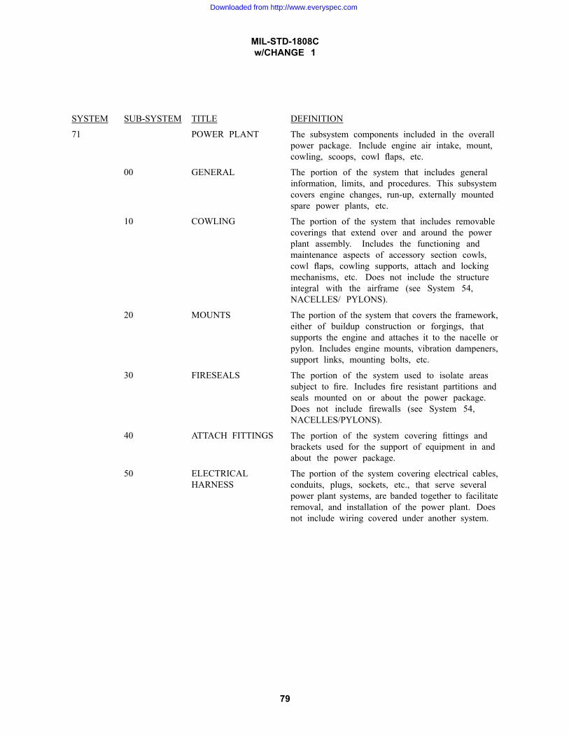
MIL-STD-1808Cw/CHANGE 1
SYSTEM SUB-SYSTEM TITLE DEFINITION
71 POWER PLANT The subsystem components included in the overallpower package. Include engine air intake, mount,cowling, scoops, cowl flaps, etc.
00 GENERAL The portion of the system that includes generalinformation, limits, and procedures. This subsystemcovers engine changes, run-up, externally mountedspare power plants, etc.
10 COWLING The portion of the system that includes removablecoverings that extend over and around the powerplant assembly. Includes the functioning andmaintenance aspects of accessory section cowls,cowl flaps, cowling supports, attach and lockingmechanisms, etc. Does not include the structureintegral with the airframe (see System 54,NACELLES/ PYLONS).
20 MOUNTS The portion of the system that covers the framework,either of buildup construction or forgings, thatsupports the engine and attaches it to the nacelle orpylon. Includes engine mounts, vibration dampeners,support links, mounting bolts, etc.
30 FIRESEALS The portion of the system used to isolate areassubject to fire. Includes fire resistant partitions andseals mounted on or about the power package.Does not include firewalls (see System 54,NACELLES/PYLONS).
40 ATTACH FITTINGS The portion of the system covering fittings andbrackets used for the support of equipment in andabout the power package.
50 ELECTRICALHARNESS
The portion of the system covering electrical cables,conduits, plugs, sockets, etc., that serve severalpower plant systems, are banded together to facilitateremoval, and installation of the power plant. Doesnot include wiring covered under another system.
79
Downloaded from http://www.everyspec.com

MIL-STD-1808Cw/CHANGE 1
SYSTEM SUB-SYSTEM TITLE DEFINITION
71 60 AIR INTAKES The portion of the system that directs and mayvary the mass air flow to the engine. Includes nosering cowls, scoops, compressor fan cowls, buriedengine ducts, vortex generators, actuators, controlhandles, cables, wiring, plumbing, linkages, doors,warning systems, position indicators, etc. Does notinclude integral airframe structure (see System 54,NACELLES/PYLONS).
70 ENGINE DRAINS The portion of the system that drain off excessfluids from the power plant and its accessories.Includes drain lines, manifolds, tanks, flamearresters, vents, and supporting brackets, etc. Alsoincludes components that are an integral part of, orfitted to, the power plant cowling.
80
Downloaded from http://www.everyspec.com
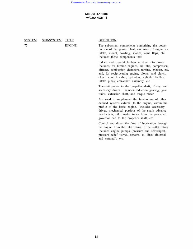
MIL-STD-1808Cw/CHANGE 1
SYSTEM SUB-SYSTEM TITLE DEFINITION
72 ENGINE The subsystem components comprising the powerportion of the power plant, exclusive of engine airintake, mount, cowling, scoops, cowl flaps, etc.Includes those components that:
Induce and convert fuel-air mixture into power.Includes, for turbine engines, air inlet, compressor,diffuser, combustion chambers, turbine, exhaust, etc,and, for reciprocating engine, blower and clutch,clutch control valve, cylinders, cylinder baffles,intake pipes, crankshaft assembly, etc.
Transmit power to the propeller shaft, if any, andaccessory drives. Includes reduction gearing, geartrains, extension shaft, and torque meter.
Are used to supplement the functioning of otherdefined systems external to the engine, within theprofile of the basic engine. Includes accessorydrives, mechanical portions of the spark advancemechanism, oil transfer tubes from the propellergovernor pad to the propeller shaft, etc.
Control and direct the flow of lubrication throughthe engine from the inlet fitting to the outlet fitting.Includes engine pumps (pressure and scavenger),pressure relief valves, screens, oil lines (internaland external), etc.
81
Downloaded from http://www.everyspec.com
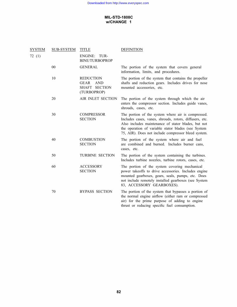
MIL-STD-1808Cw/CHANGE 1
SYSTEM SUB-SYSTEM TITLE DEFINITION
72 (1) ENGINE: TUR-BINE/TURBOPROP
00 GENERAL The portion of the system that covers generalinformation, limits, and procedures.
10 REDUCTIONGEAR ANDSHAFT SECTION(TURBOPROP)
The portion of the system that contains the propellershafts and reduction gears. Includes drives for nosemounted accessories, etc.
20 AIR INLET SECTION The portion of the system through which the airenters the compressor section. Includes guide vanes,shrouds, cases, etc.
30 COMPRESSORSECTION
The portion of the system where air is compressed.Includes cases, vanes, shrouds, rotors, diffusers, etc.Also includes maintenance of stator blades, but notthe operation of variable stator blades (see System75, AIR). Does not include compressor bleed system.
40 COMBUSTIONSECTION
The portion of the system where air and fuelare combined and burned. Includes burner cans,cases, etc.
50 TURBINE SECTION The portion of the system containing the turbines.Includes turbine nozzles, turbine rotors, cases, etc.
60 ACCESSORYSECTION
The portion of the system covering mechanicalpower takeoffs to drive accessories. Includes enginemounted gearboxes, gears, seals, pumps, etc. Doesnot include remotely installed gearboxes (see System83, ACCESSORY GEARBOXES).
70 BYPASS SECTION The portion of the system that bypasses a portion ofthe normal engine airflow (either ram or compressedair) for the prime purpose of adding to enginethrust or reducing specific fuel consumption.
82
Downloaded from http://www.everyspec.com
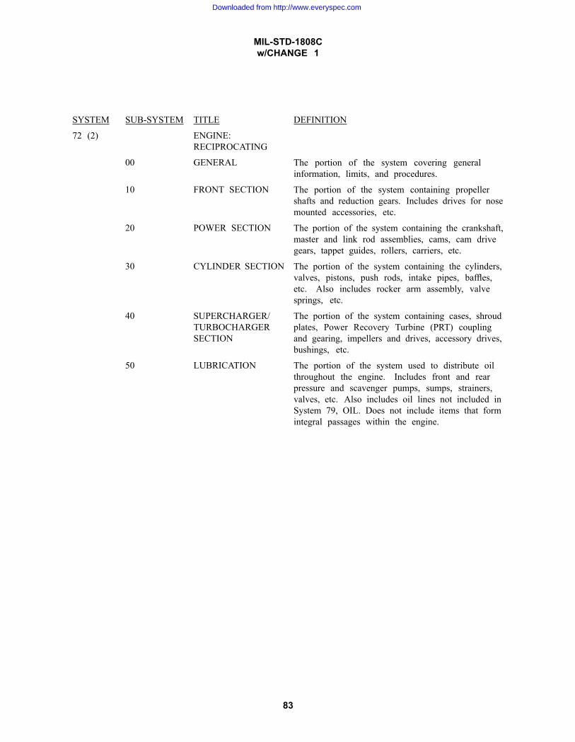
MIL-STD-1808Cw/CHANGE 1
SYSTEM SUB-SYSTEM TITLE DEFINITION
72 (2) ENGINE:RECIPROCATING
00 GENERAL The portion of the system covering generalinformation, limits, and procedures.
10 FRONT SECTION The portion of the system containing propellershafts and reduction gears. Includes drives for nosemounted accessories, etc.
20 POWER SECTION The portion of the system containing the crankshaft,master and link rod assemblies, cams, cam drivegears, tappet guides, rollers, carriers, etc.
30 CYLINDER SECTION The portion of the system containing the cylinders,valves, pistons, push rods, intake pipes, baffles,etc. Also includes rocker arm assembly, valvesprings, etc.
40 SUPERCHARGER/TURBOCHARGERSECTION
The portion of the system containing cases, shroudplates, Power Recovery Turbine (PRT) couplingand gearing, impellers and drives, accessory drives,bushings, etc.
50 LUBRICATION The portion of the system used to distribute oilthroughout the engine. Includes front and rearpressure and scavenger pumps, sumps, strainers,valves, etc. Also includes oil lines not included inSystem 79, OIL. Does not include items that formintegral passages within the engine.
83
Downloaded from http://www.everyspec.com
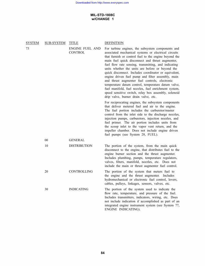
MIL-STD-1808Cw/CHANGE 1
SYSTEM SUB-SYSTEM TITLE DEFINITION
73 ENGINE FUEL ANDCONTROL
For turbine engines, the subsystem components andassociated mechanical systems or electrical circuitsthat furnish or control fuel to the engine beyond themain fuel quick disconnect and thrust augmenter,fuel flow rate sensing, transmitting, and indicatingunits whether the units are before or beyond thequick disconnect. Includes coordinator or equivalent,engine driven fuel pump and filter assembly, mainand thrust augmenter fuel controls, electronictemperature datum control, temperature datum valve,fuel manifold, fuel nozzles, fuel enrichment system,speed sensitive switch, relay box assembly, solenoiddrip valve, burner drain valve, etc.
For reciprocating engines, the subsystem componentsthat deliver metered fuel and air to the engine.The fuel portion includes the carburetor/mastercontrol from the inlet side to the discharge nozzles,injection pumps, carburetors, injection nozzles, andfuel primer. The air portion includes units fromthe scoop inlet to the vapor vent return, and theimpeller chamber. Does not include engine drivenfuel pumps (see System 28, FUEL).
00 GENERAL
10 DISTRIBUTION The portion of the system, from the main quickdisconnect to the engine, that distributes fuel to theengine burner section and the thrust augmenter.Includes plumbing, pumps, temperature regulators,valves, filters, manifold, nozzles, etc. Does notinclude the main or thrust augmenter fuel control.
20 CONTROLLING The portion of the system that meters fuel tothe engine and the thrust augmenter. Includeshydromechanical or electronic fuel control, levers,cables, pulleys, linkages, sensors, valves, etc.
30 INDICATING The portion of the system used to indicate theflow rate, temperature, and pressure of the fuel.Includes transmitters, indicators, wiring, etc. Doesnot include indication if accomplished as part of anintegrated engine instrument system (see System 77,ENGINE INDICATING).
84
Downloaded from http://www.everyspec.com
MIL-STD-1808Cw/CHANGE 1
SYSTEM SUB-SYSTEM TITLE DEFINITION
74 ENGINE IGNITION The subsystem components that generate, control,furnish, or distribute an electrical current to ignitethe fuel-air mixture in the cylinders of reciprocatingengines, or in the combustion chambers orthrust augmenters of turbine engines. Includesinduction vibrators, magnetos, switches, lead filters,distributors, harnesses, spark plugs, ignition relays,exciters, and the electrical portion of the sparkadvance mechanism.
00 GENERAL
10 ELECTRICALPOWER SUPPLY
The portion of the system that generates electricalcurrent for the purpose of igniting the fuel-airmixture. Includes magnetos, distributors, boostercoils, exciters, transformers, storage capacitors,compositors, etc.
20 DISTRIBUTION The portion of the system that conducts high orlow voltage electricity from the electrical powersupply to the spark plugs or igniters. Includeswiring between magneto and distributor in thosesystems where they are separate units. Includesignition harness, high tension leads, coils as used in"low tension" systems, spark plugs, igniters, etc.
30 SWITCHING The portion of the system that provides a means ofrendering the electrical power supply inoperative.Includes ignition switches, wiring, connectors, etc.
85
Downloaded from http://www.everyspec.com
MIL-STD-1808Cw/CHANGE 1
SYSTEM SUB-SYSTEM TITLE DEFINITION
75 ENGINE AIR For turbine engines, the subsystem externalcomponents and integral basic engine parts thatgo together to conduct air to various portions ofthe engine and to the extension shaft and torquemeter, assembly, if any. Includes compressorbleed systems, cooling air systems, and heatedair systems (engine anti-icing). Does not includeaircraft anti-icing, engine starting systems or exhaustsupplementary air systems.
00 GENERAL
10 ENGINE ANTI-ICING The portion of the system using bleed air toprevent or eliminate the formation of ice in allparts of the engine, includes valves, plumbing,wiring, radiators, etc. Excludes power plant cowlingand electrical anti-icing (see System 30, ICE ANDRAIN PROTECTION).
20 COOLING The portion of the system used to ventilate theengine and accessories. Includes valves, plumbing,wiring, jet pumps, vortex spoilers, etc.
30 COMPRESSORCONTROL
The portion of the system used to control the flowof air through the engine. Includes governors,valves, actuators, linkages, etc. Also includes theoperation of variable stator blades. Does not includemaintenance covered in System 72, ENGINE.
40 INDICATING The portion of the system used to indicatetemperature, pressure, control positions, etc., ofthe air systems. Includes transmitters, indicators,wiring, etc.
86
Downloaded from http://www.everyspec.com
MIL-STD-1808Cw/CHANGE 1
SYSTEM SUB-SYSTEM TITLE DEFINITION
76 ENGINE CONTROLS The subsystem controls that govern operationof the engine. Includes units and componentsinterconnected for emergency shutdown. Forturboprop engines, includes linkages and controls tothe coordinator or equivalent, the propeller governor,fuel control unit, or other units being controlled.For reciprocating engines, includes controls forblowers. Does not include units or componentsspecifically included in other systems.
00 GENERAL
10 POWER CONTROL The portion of the system that furnishes a meansof controlling the main fuel control or coordinator.Includes controls to the propeller regulator onturboprop engines. Includes linkages, cables, levers,pulleys, switches, wiring, etc. Does not includethe units themselves.
20 EMERGENCYSHUTDOWN
The portion of the system that furnishes a meansof controlling the flow of fluids to and from theengine during emergency procedures. Includeslevers, cables, pulleys, linkages, switches, wiring,etc. Does not include the units themselves.
87
Downloaded from http://www.everyspec.com
MIL-STD-1808Cw/CHANGE 1
SYSTEM SUB-SYSTEM TITLE DEFINITION
77 ENGINEINDICATING
The subsystem components and associated systemsthat indicate engine operation. Includes indicators,transmitters, analyzers, etc. For turboprop engines,includes phase detectors. Does not include systemsor items specifically included in other systemsexcept when indication is accomplished as apart of an integrated engine instrument system(see Subsystem 40, INTEGRATED ENGINEINSTRUMENT SYSTEMS).
00 GENERAL
10 POWER The portion of the system that directly orindirectly indicates power or thrust. Includes BrakeMean Effective Pressure (BMEP), pressure ratio,Revolutions Per Minute (RPM), etc.
20 TEMPERATURE The portion of the system that indicates temperaturesin the engine. Includes cylinder head, exhaust(turbine inlet), etc.
30 ANALYZERS The portion of the system used to analyze engineperformance or condition by means of instruments ordevices, such as oscilloscopes. Includes generators,wiring, amplifiers, oscilloscopes, etc.
40 INTEGRATEDENGINEINSTRUMENTSYSTEMS
The portion of the system that, in an integratedconcept, receives several or all engine operatingparameters and transmits them to a central processorfor presentation to the flight crew. Includes displayunits, transmitters, receivers, computers, etc.
50 ENGINEMONITORINGSYSTEM
The portion of the system that monitors engineoperation, issues flight crew warnings onpredetermined malfunctions, and stores engineinformation for later use by maintenance personnel.
88
Downloaded from http://www.everyspec.com
MIL-STD-1808Cw/CHANGE 1
SYSTEM SUB-SYSTEM TITLE DEFINITION
78 ENGINE EXHAUST The subsystem components that direct engineexhaust gases overboard.
For turbine engines, includes units external to thebasic engine such as thrust reverser and noisesuppressor.
For reciprocating engines, includes augmenters,stacks, clamps, etc. Excludes exhaust driventurbines.
00 GENERAL
10 COLLECTOR/NOZ-ZLE
The portion of the system that collects exhaustgases from the cylinders or turbines and conductsthem overboard. Includes collector rings, exhaust,and thrust augmenter ducts (unless included inSubsystem 50, AUGMENTER), variable nozzles,actuators, plumbing, linkages, wiring, positionindicators, warning systems, etc. Does not includepower recovery turbines, turbo/superchargers, noisesuppressors, or thrust reversers when they are notan integral part of the nozzle system.
20 NOISE SUPPRESSOR The portion of the system that reduces the noisegenerated by the exhaust gases. Includes pipes,baffles, shields, actuators, plumbing, linkages,wiring, position indicators, warning systems, etc.
Use Subsystem 10, COLLECTOR/NOZZLE, whenan integral part of the nozzle system.
30 THRUST REVERSER The portion of the system used to change thedirection of the exhaust gases for reverse thrust.Includes clamshells, linkages, levers, actuators,plumbing, wiring, position indicators, warningsystems, etc.
Use Subsystem 10, COLLECTOR/NOZZLE, whenan integral part of nozzle system.
40 SUPPLEMENTARYAIR
The portion of the system that varies and controlssupplementary air flow to the exhaust system.Includes tertiary air doors, actuators, linkages,springs, plumbing, wiring, position indicators,warning systems, etc.
50 AUGMENTER The portion of the system that provides additionalthrust for takeoff and in flight at the command ofthe pilot. Includes liners, rings, ducts, actuators,linkages, wiring, indicators, warning systems,etc. Does not include augmentation external tothe power plant (see System 84, PROPULSIONAUGMENTATION).
89
Downloaded from http://www.everyspec.com
MIL-STD-1808Cw/CHANGE 1
SYSTEM SUB-SYSTEM TITLE DEFINITION
79 ENGINE OIL The subsystem components external to the engineconcerned with storing and delivering lubricatingoil to and from the engine. Covers all units andcomponents from the lubricating oil engine outlet tothe inlet, including the inlet and outlet fittings, tank,radiator, bypass valve, auxiliary oil systems, etc.
00 GENERAL
10 STORAGE The portion of the system used for storage of oil.Includes tanks, filling systems, internal hoppers,baffles, tank sump and drain, etc. Does not includetanks that are an integral part of the engine.
20 DISTRIBUTION The portion of the system used to conduct oilfrom and to the engine. Includes plumbing, valves,temperature regulator, control systems, etc.
30 INDICATING The portion of the system used to indicate thequantity, temperature, and pressure of the oil.Includes transmitters, indicators, wiring, warningsystems, etc. Does not include indication ifaccomplished as part of an integrated engineinstrument system (see System 77, ENGINEINDICATING).
90
Downloaded from http://www.everyspec.com
MIL-STD-1808Cw/CHANGE 1
SYSTEM SUB-SYSTEM TITLE DEFINITION
80 ENGINE STARTING The subsystem components and associated systemsused for starting the engine. Includes electrical,inertia air, or other starter systems. Does not includeignition systems (see System 74, IGNITION).
00 GENERAL
10 CRANKING The portion of the system used to perform thecranking portion of the starting operation. Includesplumbing, valves, wiring, starter, switches, relays,etc.
91
Downloaded from http://www.everyspec.com
MIL-STD-1808Cw/CHANGE 1
SYSTEM SUB-SYSTEM TITLE DEFINITION
81 TURBINES For reciprocating engines only. The subsystemcomponents that include Power Recovery Turbine(PRT) assembly and turbo/super-charger unit whenexternal to the engine.
00 GENERAL
10 POWER RECOVERY The portion of the system that includes turbinesthat extract energy from the exhaust gases and arecoupled to the crankshaft.
20 TURBO/SUPER-CHARGER
The portion of the system that includes turbinesthat extract energy from the exhaust gases anddrive an air compressor.
92
Downloaded from http://www.everyspec.com
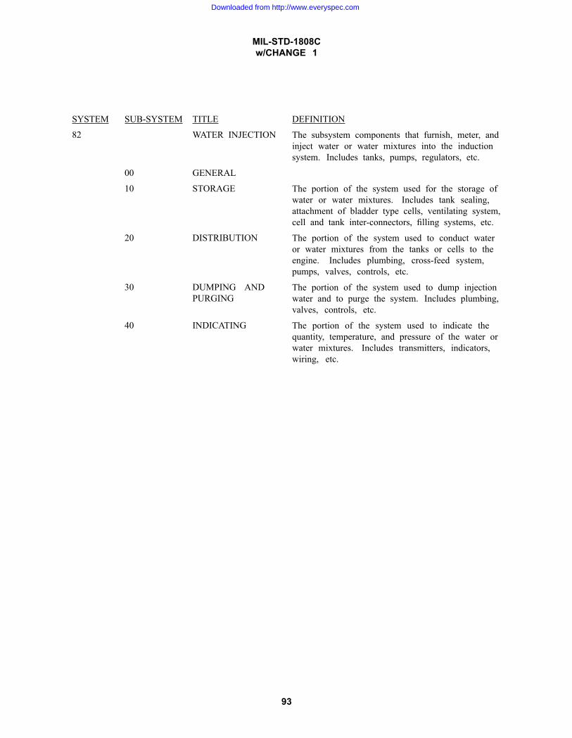
MIL-STD-1808Cw/CHANGE 1
SYSTEM SUB-SYSTEM TITLE DEFINITION
82 WATER INJECTION The subsystem components that furnish, meter, andinject water or water mixtures into the inductionsystem. Includes tanks, pumps, regulators, etc.
00 GENERAL
10 STORAGE The portion of the system used for the storage ofwater or water mixtures. Includes tank sealing,attachment of bladder type cells, ventilating system,cell and tank inter-connectors, filling systems, etc.
20 DISTRIBUTION The portion of the system used to conduct wateror water mixtures from the tanks or cells to theengine. Includes plumbing, cross-feed system,pumps, valves, controls, etc.
30 DUMPING ANDPURGING
The portion of the system used to dump injectionwater and to purge the system. Includes plumbing,valves, controls, etc.
40 INDICATING The portion of the system used to indicate thequantity, temperature, and pressure of the water orwater mixtures. Includes transmitters, indicators,wiring, etc.
93
Downloaded from http://www.everyspec.com
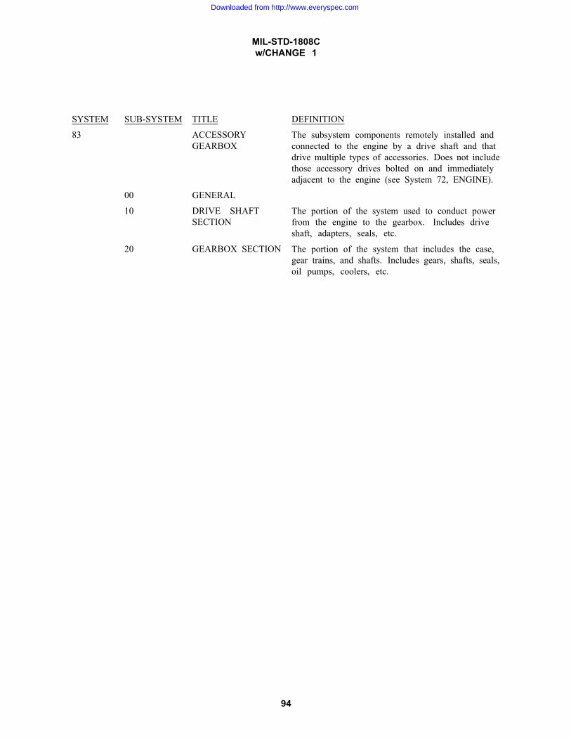
MIL-STD-1808Cw/CHANGE 1
SYSTEM SUB-SYSTEM TITLE DEFINITION
83 ACCESSORYGEARBOX
The subsystem components remotely installed andconnected to the engine by a drive shaft and thatdrive multiple types of accessories. Does not includethose accessory drives bolted on and immediatelyadjacent to the engine (see System 72, ENGINE).
00 GENERAL
10 DRIVE SHAFTSECTION
The portion of the system used to conduct powerfrom the engine to the gearbox. Includes driveshaft, adapters, seals, etc.
20 GEARBOX SECTION The portion of the system that includes the case,gear trains, and shafts. Includes gears, shafts, seals,oil pumps, coolers, etc.
94
Downloaded from http://www.everyspec.com
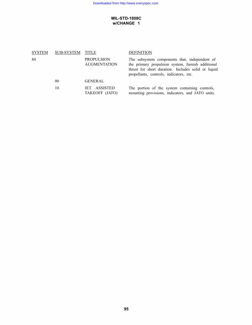
MIL-STD-1808Cw/CHANGE 1
SYSTEM SUB-SYSTEM TITLE DEFINITION
84 PROPULSIONAUGMENTATION
The subsystem components that, independent ofthe primary propulsion system, furnish additionalthrust for short duration. Includes solid or liquidpropellants, controls, indicators, etc.
00 GENERAL
10 JET ASSISTEDTAKEOFF (JATO)
The portion of the system containing controls,mounting provisions, indicators, and JATO units.
95
Downloaded from http://www.everyspec.com

MIL-STD-1808Cw/CHANGE 1
SYSTEM SUB-SYSTEM TITLE DEFINITION
85 UNASSIGNED
96
Downloaded from http://www.everyspec.com
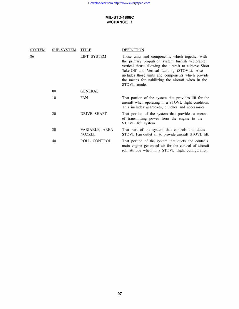
MIL-STD-1808Cw/CHANGE 1
SYSTEM SUB-SYSTEM TITLE DEFINITION
86 LIFT SYSTEM Those units and components, which together withthe primary propulsion system furnish vectorablevertical thrust allowing the aircraft to achieve ShortTake-Off and Vertical Landing (STOVL). Alsoincludes those units and components which providethe means for stabilizing the aircraft when in theSTOVL mode.
00 GENERAL
10 FAN That portion of the system that provides lift for theaircraft when operating in a STOVL flight condition.This includes gearboxes, clutches and accessories.
20 DRIVE SHAFT That portion of the system that provides a meansof transmitting power from the engine to theSTOVL lift system.
30 VARIABLE AREANOZZLE
That part of the system that controls and ductsSTOVL Fan outlet air to provide aircraft STOVL lift.
40 ROLL CONTROL That portion of the system that ducts and controlsmain engine generated air for the control of aircraftroll attitude when in a STOVL flight configuration.
97
Downloaded from http://www.everyspec.com
MIL-STD-1808Cw/CHANGE 1
SYSTEM SUB-SYSTEM TITLE DEFINITION
87THRU89
UNASSIGNED
98
Downloaded from http://www.everyspec.com
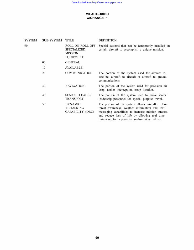
MIL-STD-1808Cw/CHANGE 1
SYSTEM SUB-SYSTEM TITLE DEFINITION
90 ROLL-ON ROLL-OFFSPECIALIZEDMISSIONEQUIPMENT
Special systems that can be temporarily installed oncertain aircraft to accomplish a unique mission.
00 GENERAL
10 AVAILABLE
20 COMMUNICATION The portion of the system used for aircraft tosatellite, aircraft to aircraft or aircraft to groundcommunications.
30 NAVIGATION The portion of the system used for precision airdrop, tanker interception, troop location.
40 SENIOR LEADERTRANSPORT
The portion of the system used to move seniorleadership personnel for special purpose travel.
50 DYNAMICRE-TASKINGCAPABILITY (DRC)
The portion of the system allows aircraft to havethreat awareness, weather information and textmessaging capabilities to increase mission successand reduce loss of life by allowing real timere-tasking for a potential mid-mission redirect.
99
Downloaded from http://www.everyspec.com
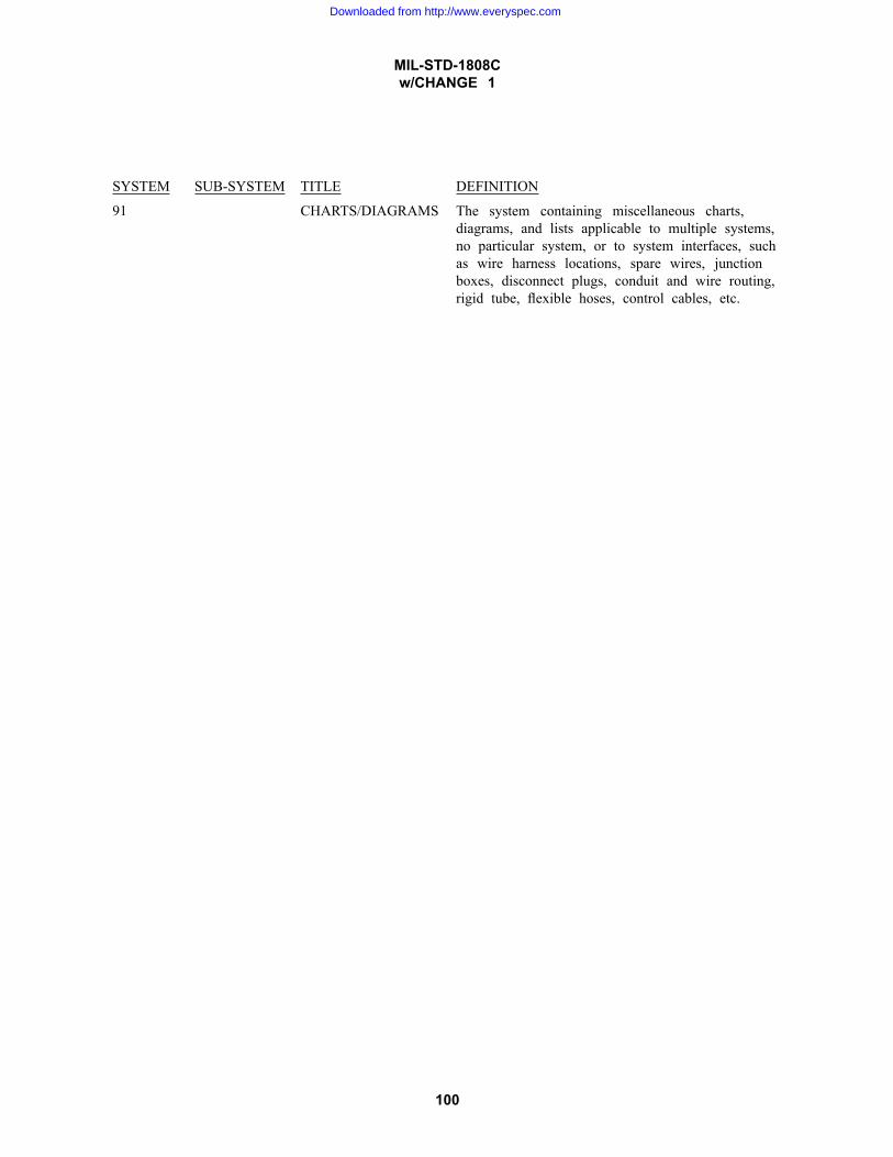
MIL-STD-1808Cw/CHANGE 1
SYSTEM SUB-SYSTEM TITLE DEFINITION
91 CHARTS/DIAGRAMS The system containing miscellaneous charts,diagrams, and lists applicable to multiple systems,no particular system, or to system interfaces, suchas wire harness locations, spare wires, junctionboxes, disconnect plugs, conduit and wire routing,rigid tube, flexible hoses, control cables, etc.
100
Downloaded from http://www.everyspec.com
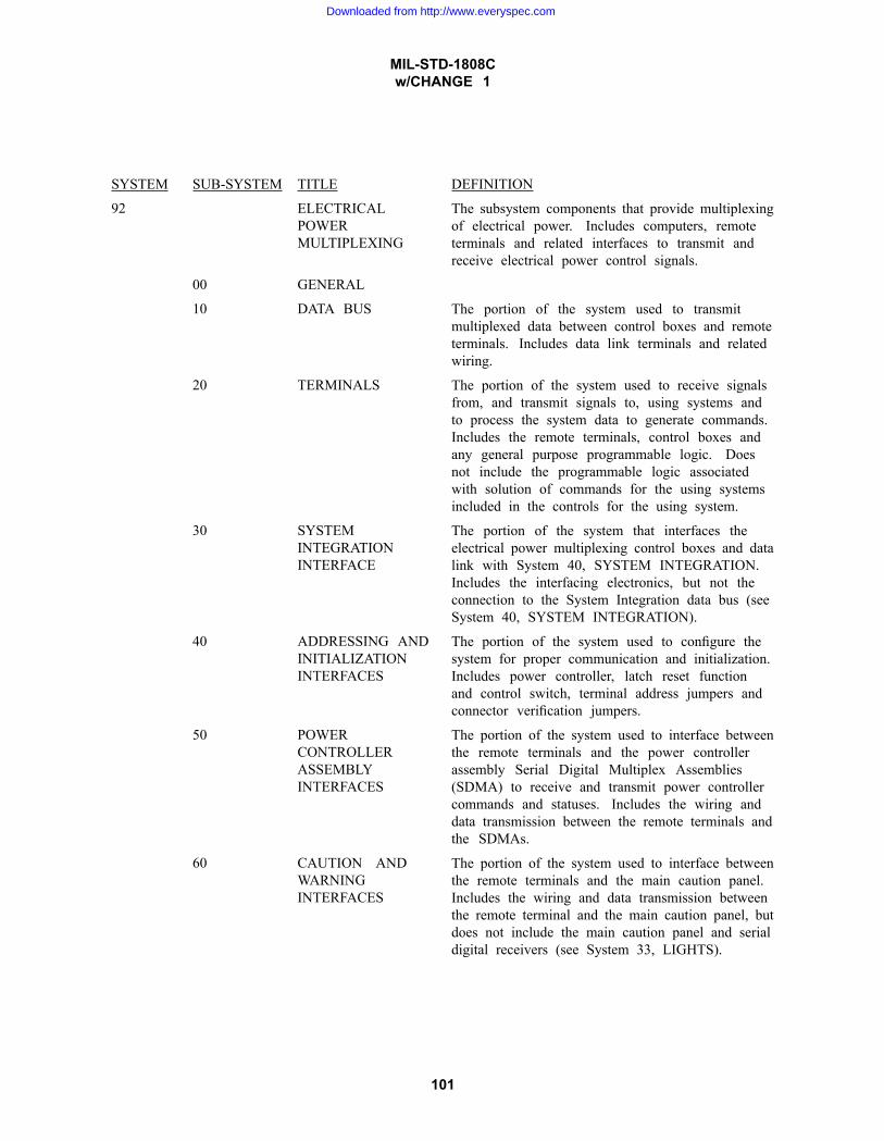
MIL-STD-1808Cw/CHANGE 1
SYSTEM SUB-SYSTEM TITLE DEFINITION
92 ELECTRICALPOWERMULTIPLEXING
The subsystem components that provide multiplexingof electrical power. Includes computers, remoteterminals and related interfaces to transmit andreceive electrical power control signals.
00 GENERAL
10 DATA BUS The portion of the system used to transmitmultiplexed data between control boxes and remoteterminals. Includes data link terminals and relatedwiring.
20 TERMINALS The portion of the system used to receive signalsfrom, and transmit signals to, using systems andto process the system data to generate commands.Includes the remote terminals, control boxes andany general purpose programmable logic. Doesnot include the programmable logic associatedwith solution of commands for the using systemsincluded in the controls for the using system.
30 SYSTEMINTEGRATIONINTERFACE
The portion of the system that interfaces theelectrical power multiplexing control boxes and datalink with System 40, SYSTEM INTEGRATION.Includes the interfacing electronics, but not theconnection to the System Integration data bus (seeSystem 40, SYSTEM INTEGRATION).
40 ADDRESSING ANDINITIALIZATIONINTERFACES
The portion of the system used to configure thesystem for proper communication and initialization.Includes power controller, latch reset functionand control switch, terminal address jumpers andconnector verification jumpers.
50 POWERCONTROLLERASSEMBLYINTERFACES
The portion of the system used to interface betweenthe remote terminals and the power controllerassembly Serial Digital Multiplex Assemblies(SDMA) to receive and transmit power controllercommands and statuses. Includes the wiring anddata transmission between the remote terminals andthe SDMAs.
60 CAUTION ANDWARNINGINTERFACES
The portion of the system used to interface betweenthe remote terminals and the main caution panel.Includes the wiring and data transmission betweenthe remote terminal and the main caution panel, butdoes not include the main caution panel and serialdigital receivers (see System 33, LIGHTS).
101
Downloaded from http://www.everyspec.com
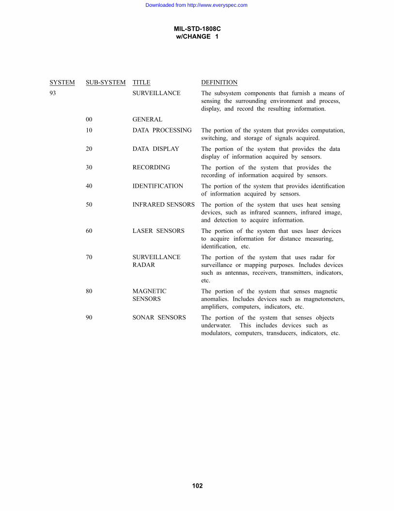
MIL-STD-1808Cw/CHANGE 1
SYSTEM SUB-SYSTEM TITLE DEFINITION
93 SURVEILLANCE The subsystem components that furnish a means ofsensing the surrounding environment and process,display, and record the resulting information.
00 GENERAL
10 DATA PROCESSING The portion of the system that provides computation,switching, and storage of signals acquired.
20 DATA DISPLAY The portion of the system that provides the datadisplay of information acquired by sensors.
30 RECORDING The portion of the system that provides therecording of information acquired by sensors.
40 IDENTIFICATION The portion of the system that provides identificationof information acquired by sensors.
50 INFRARED SENSORS The portion of the system that uses heat sensingdevices, such as infrared scanners, infrared image,and detection to acquire information.
60 LASER SENSORS The portion of the system that uses laser devicesto acquire information for distance measuring,identification, etc.
70 SURVEILLANCERADAR
The portion of the system that uses radar forsurveillance or mapping purposes. Includes devicessuch as antennas, receivers, transmitters, indicators,etc.
80 MAGNETICSENSORS
The portion of the system that senses magneticanomalies. Includes devices such as magnetometers,amplifiers, computers, indicators, etc.
90 SONAR SENSORS The portion of the system that senses objectsunderwater. This includes devices such asmodulators, computers, transducers, indicators, etc.
102
Downloaded from http://www.everyspec.com
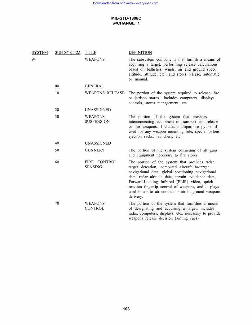
MIL-STD-1808Cw/CHANGE 1
SYSTEM SUB-SYSTEM TITLE DEFINITION
94 WEAPONS The subsystem components that furnish a means ofacquiring a target, performing release calculationsbased on ballistics, winds, air and ground speed,altitude, attitude, etc., and stores release, automaticor manual.
00 GENERAL
10 WEAPONS RELEASE The portion of the system required to release, fireor jettison stores. Includes computers, displays,controls, stores management, etc.
20 UNASSIGNED
30 WEAPONSSUSPENSION
The portion of the system that providesinterconnecting equipment to transport and releaseor fire weapons. Includes multipurpose pylons ifused for any weapon mounting role, special pylons,ejection racks, launchers, etc.
40 UNASSIGNED
50 GUNNERY The portion of the system consisting of all gunsand equipment necessary to fire stores.
60 FIRE CONTROLSENSING
The portion of the system that provides radartarget detection, computed aircraft to-targetnavigational data, global positioning navigationaldata, radar altitude data, terrain avoidance data,Forward-Looking Infrared (FLIR) video, quickreaction fingertip control of weapons, and displaysused in air to air combat or air to ground weaponsdelivery.
70 WEAPONSCONTROL
The portion of the system that furnishes a meansof designating and acquiring a target, includesradar, computers, displays, etc., necessary to provideweapons release decision (aiming cues).
103
Downloaded from http://www.everyspec.com
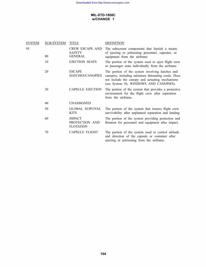
MIL-STD-1808Cw/CHANGE 1
SYSTEM SUB-SYSTEM TITLE DEFINITION
95 CREW ESCAPE ANDSAFETY
The subsystem components that furnish a meansof ejecting or jettisoning personnel, capsules, orequipment from the airframe.00 GENERAL
10 EJECTION SEATS The portion of the system used to eject flight crewor passenger seats individually from the airframe.
20 ESCAPEHATCHES/CANOPIES
The portion of the system involving hatches andcanopies, including miniature detonating cords. Doesnot include the canopy and actuating mechanisms(see System 56, WINDOWS AND CANOPIES).
30 CAPSULE EJECTION The portion of the system that provides a protectiveenvironment for the flight crew after separationfrom the airframe.
40 UNASSIGNED
50 GLOBAL SURVIVALKITS
The portion of the system that insures flight crewsurvivability after unplanned separation and landing.
60 IMPACTPROTECTION ANDFLOTATION
The portion of the system providing protection andflotation for personnel and equipment after impact.
70 CAPSULE FLIGHT The portion of the system used to control attitudeand direction of the capsule or container afterejecting or jettisoning from the airframe.
104
Downloaded from http://www.everyspec.com
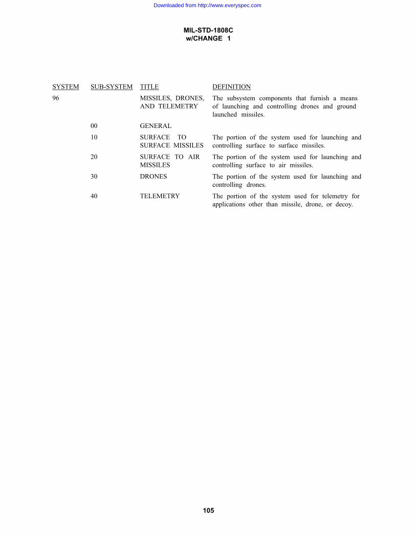
MIL-STD-1808Cw/CHANGE 1
SYSTEM SUB-SYSTEM TITLE DEFINITION
96 MISSILES, DRONES,AND TELEMETRY
The subsystem components that furnish a meansof launching and controlling drones and groundlaunched missiles.
00 GENERAL
10 SURFACE TOSURFACE MISSILES
The portion of the system used for launching andcontrolling surface to surface missiles.
20 SURFACE TO AIRMISSILES
The portion of the system used for launching andcontrolling surface to air missiles.
30 DRONES The portion of the system used for launching andcontrolling drones.
40 TELEMETRY The portion of the system used for telemetry forapplications other than missile, drone, or decoy.
105
Downloaded from http://www.everyspec.com
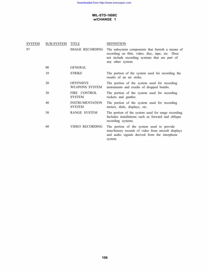
MIL-STD-1808Cw/CHANGE 1
SYSTEM SUB-SYSTEM TITLE DEFINITION
97 IMAGE RECORDING The subsystem components that furnish a means ofrecording on film, video, disc, tape, etc. Doesnot include recording systems that are part ofany other system.
00 GENERAL
10 STRIKE The portion of the system used for recording theresults of an air strike.
20 OFFENSIVEWEAPONS SYSTEM
The portion of the system used for recordinginstruments and results of dropped bombs.
30 FIRE CONTROLSYSTEM
The portion of the system used for recordingrockets and gunfire.
40 INSTRUMENTATIONSYSTEM
The portion of the system used for recordingmeters, dials, displays, etc.
50 RANGE SYSTEM The portion of the system used for range recording.Includes installations such as forward and obliquerecording systems.
60 VIDEO RECORDING The portion of the system used to providetime/history records of video from aircraft displaysand audio signals derived from the interphonesystem.
106
Downloaded from http://www.everyspec.com
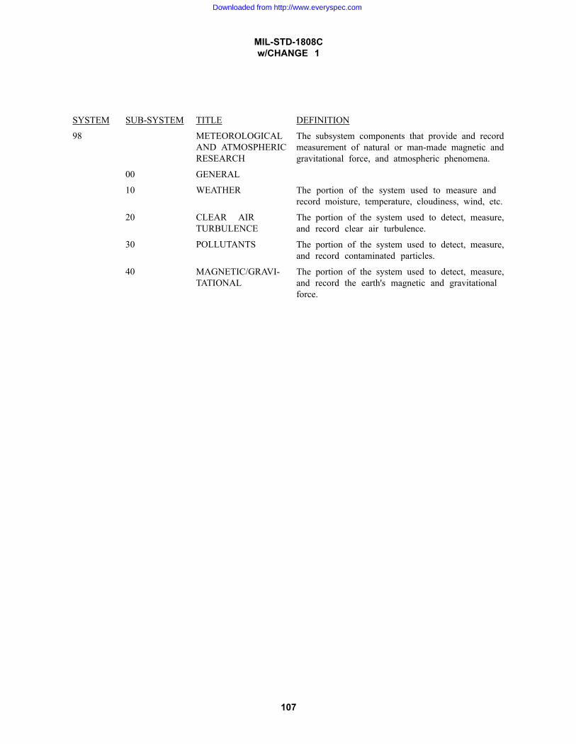
MIL-STD-1808Cw/CHANGE 1
SYSTEM SUB-SYSTEM TITLE DEFINITION
98 METEOROLOGICALAND ATMOSPHERICRESEARCH
The subsystem components that provide and recordmeasurement of natural or man-made magnetic andgravitational force, and atmospheric phenomena.
00 GENERAL
10 WEATHER The portion of the system used to measure andrecord moisture, temperature, cloudiness, wind, etc.
20 CLEAR AIRTURBULENCE
The portion of the system used to detect, measure,and record clear air turbulence.
30 POLLUTANTS The portion of the system used to detect, measure,and record contaminated particles.
40 MAGNETIC/GRAVI-TATIONAL
The portion of the system used to detect, measure,and record the earth's magnetic and gravitationalforce.
107
Downloaded from http://www.everyspec.com
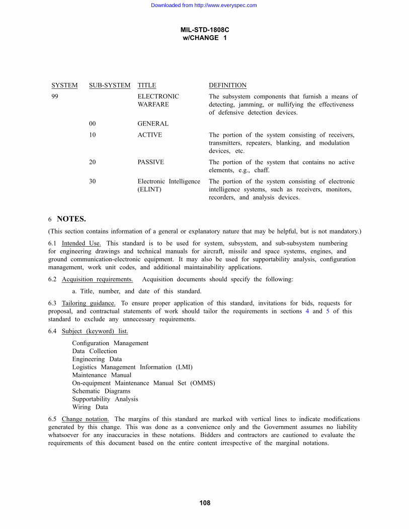
MIL-STD-1808Cw/CHANGE 1
SYSTEM SUB-SYSTEM TITLE DEFINITION
99 ELECTRONICWARFARE
The subsystem components that furnish a means ofdetecting, jamming, or nullifying the effectivenessof defensive detection devices.
00 GENERAL
10 ACTIVE The portion of the system consisting of receivers,transmitters, repeaters, blanking, and modulationdevices, etc.
20 PASSIVE The portion of the system that contains no activeelements, e.g., chaff.
30 Electronic Intelligence(ELINT)
The portion of the system consisting of electronicintelligence systems, such as receivers, monitors,recorders, and analysis devices.
6 NOTES.(This section contains information of a general or explanatory nature that may be helpful, but is not mandatory.)
6.1 Intended Use. This standard is to be used for system, subsystem, and sub-subsystem numberingfor engineering drawings and technical manuals for aircraft, missile and space systems, engines, andground communication-electronic equipment. It may also be used for supportability analysis, configurationmanagement, work unit codes, and additional maintainability applications.
6.2 Acquisition requirements. Acquisition documents should specify the following:
a. Title, number, and date of this standard.
6.3 Tailoring guidance. To ensure proper application of this standard, invitations for bids, requests forproposal, and contractual statements of work should tailor the requirements in sections 4 and 5 of thisstandard to exclude any unnecessary requirements.
6.4 Subject (keyword) list.
Configuration ManagementData CollectionEngineering DataLogistics Management Information (LMI)Maintenance ManualOn-equipment Maintenance Manual Set (OMMS)Schematic DiagramsSupportability AnalysisWiring Data
6.5 Change notation. The margins of this standard are marked with vertical lines to indicate modificationsgenerated by this change. This was done as a convenience only and the Government assumes no liabilitywhatsoever for any inaccuracies in these notations. Bidders and contractors are cautioned to evaluate therequirements of this document based on the entire content irrespective of the marginal notations.
108
Downloaded from http://www.everyspec.com
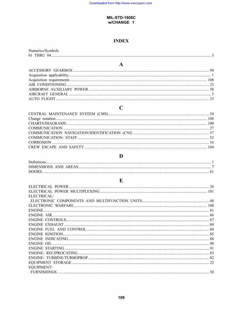
MIL-STD-1808Cw/CHANGE 1
INDEX
Numerics/Symbols01 THRU 04.................................................................................................................................................................. 3
AACCESSORY GEARBOX.......................................................................................................................................... 94Acquisition applicability................................................................................................................................................ 1Acquisition requirements ........................................................................................................................................... 108AIR CONDITIONING ................................................................................................................................................ 23AIRBORNE AUXILIARY POWER.......................................................................................................................... 58AIRCRAFT GENERAL ................................................................................................................................................ 5AUTO FLIGHT ........................................................................................................................................................... 25
CCENTRAL MAINTENANCE SYSTEM (CMS)...................................................................................................... 54Change notation ......................................................................................................................................................... 108CHARTS/DIAGRAMS............................................................................................................................................... 100COMMUNICATION .................................................................................................................................................... 27COMMUNICATION NAVIGATION/IDENTIFICATION (CNI) ............................................................................. 57COMMUNICATION: STAFF ..................................................................................................................................... 52CORROSION ............................................................................................................................................................... 16CREW ESCAPE AND SAFETY ............................................................................................................................ 104
DDefinitions....................................................................................................................................................................... 1DIMENSIONS AND AREAS ...................................................................................................................................... 7DOORS......................................................................................................................................................................... 61
EELECTRICAL POWER.............................................................................................................................................. 28ELECTRICAL POWER MULTIPLEXING............................................................................................................. 101ELECTRICAL/ELECTRONIC COMPONENTS AND MULTIFUNCTION UNITS.................................................................... 48ELECTRONIC WARFARE....................................................................................................................................... 108ENGINE........................................................................................................................................................................ 81ENGINE AIR............................................................................................................................................................... 86ENGINE CONTROLS................................................................................................................................................. 87ENGINE EXHAUST................................................................................................................................................... 89ENGINE FUEL AND CONTROL ............................................................................................................................ 84ENGINE IGNITION.................................................................................................................................................... 85ENGINE INDICATING............................................................................................................................................... 88ENGINE OIL............................................................................................................................................................... 90ENGINE STARTING .................................................................................................................................................. 91ENGINE: RECIPROCATING..................................................................................................................................... 83ENGINE: TURBINE/TURBOPROP .......................................................................................................................... 82EQUIPMENT STORAGE........................................................................................................................................... 22EQUIPMENT/FURNISHINGS .......................................................................................................................................................... 30
109
Downloaded from http://www.everyspec.com
MIL-STD-1808Cw/CHANGE 1
FFIRE PROTECTION................................................................................................................................................... 32FLIGHT CONTROLS ................................................................................................................................................. 33FOLDING BLADES/PYLON..................................................................................................................................... 75FUEL ............................................................................................................................................................................ 35Function number ............................................................................................................................................................ 3FUSELAGE .................................................................................................................................................................. 63
GGeneral............................................................................................................................................................................ 1Government documents ................................................................................................................................................. 1
HHYDRAULIC POWER............................................................................................................................................... 37
IICE AND RAIN PROTECTION............................................................................................................................... 38IMAGE RECORDING .............................................................................................................................................. 106IN-FLIGHT REFUELING: TANKER ....................................................................................................................... 53INDICATING/RECORDING SYSTEMS ......................................................................................................................................... 39INTEGRATED AVIONICS ARCHITECTURE......................................................................................................... 51Intended Use .............................................................................................................................................................. 108
LLANDING GEAR ....................................................................................................................................................... 40LEVELING AND WEIGHING.................................................................................................................................... 9LIFT SYSTEM ............................................................................................................................................................ 97LIFTING, JACKING, AND SHORING ..................................................................................................................... 8LIGHTS ........................................................................................................................................................................ 42LIQUID/GASEOUS NITROGEN............................................................................................................................... 56
MMETEOROLOGICAL AND ATMOSPHERIC RESEARCH ................................................................................ 107MISSILES, DRONES, AND TELEMETRY .......................................................................................................... 105
NNACELLES/PYLONS ................................................................................................................................................. 64NAVIGATION .............................................................................................................................................................. 43NON-DESTRUCTIVE INSPECTION........................................................................................................................ 17Number composition...................................................................................................................................................... 2
OOrder of precedence...................................................................................................................................................... 1Other government documents, drawings and publications ........................................................................................ 1OXYGEN...................................................................................................................................................................... 44
PPARKING AND MOORING ..................................................................................................................................... 12PLACARDS AND MARKINGS................................................................................................................................ 13PNEUMATIC................................................................................................................................................................ 45
110
Downloaded from http://www.everyspec.com
MIL-STD-1808Cw/CHANGE 1
POWER PLANT.......................................................................................................................................................... 79PREPARATION FOR USE AND SHIPMENT (GROUND EQUIPMENT ONLY) ............................................ 19PROPELLERS/PROPULSORS ........................................................................................................................................................... 70PROPULSION AUGMENTATION ............................................................................................................................ 95
RROLL-ON ROLL-OFF SPECIALIZED MISSION EQUIPMENT......................................................................... 99ROTOR DRIVES......................................................................................................................................................... 72ROTOR FLIGHT CONTROLS.................................................................................................................................. 76ROTORS....................................................................................................................................................................... 71
SScope............................................................................................................................................................................... 1SERVICING ................................................................................................................................................................. 14SITING INSTALLATION (GROUND EQUIPMENT ONLY) ............................................................................... 18Specifications, standards and handbooks..................................................................................................................... 1STABILIZERS.............................................................................................................................................................. 65STANDARD PRACTICES: ENGINE ....................................................................................................................... 78STANDARD PRACTICES: INTEGRATED AVIONICS......................................................................................... 49STANDARD PRACTICES: PROPELLERS.............................................................................................................. 69STANDARD PRACTICES: STRUCTURES............................................................................................................. 60Sub-subsystem number .................................................................................................................................................. 2Subject (keyword) list ............................................................................................................................................... 108Subject number .............................................................................................................................................................. 3Subsystem number ......................................................................................................................................................... 2SURVEILLANCE....................................................................................................................................................... 102SYSTEM INTEGRATION AND DISPLAY............................................................................................................. 55System number .............................................................................................................................................................. 2System numbering ......................................................................................................................................................... 3System Subsystem Sub-subsystem Number (SSSN).................................................................................................. 2
TTAIL ROTOR .............................................................................................................................................................. 73TAIL ROTOR DRIVE................................................................................................................................................ 74Tailoring guidance ..................................................................................................................................................... 108TIME LIMITS, INSPECTIONS, AND MAINTENANCE CHECKS .................................................................... 15TOWING AND TAXIING ..........................................................................................................................................11TRAINING EQUIPMENT .......................................................................................................................................... 21TURBINES................................................................................................................................................................... 92Typical system subsystem sub-subsystem number composition ............................................................................... 3
UUse of SSSN ................................................................................................................................................................. 3
VVACUUM ..................................................................................................................................................................... 46
WWATER BALLAST ..................................................................................................................................................... 50WATER INJECTION................................................................................................................................................... 93
111
Downloaded from http://www.everyspec.com
MIL-STD-1808Cw/CHANGE 1
WATER/WASTE........................................................................................................................................................... 47WEAPONS ................................................................................................................................................................. 103WEAPONS INSTRUMENTATION............................................................................................................................ 20WINDOWS AND CANOPIES................................................................................................................................... 66WINGS ......................................................................................................................................................................... 67
112
Downloaded from http://www.everyspec.com
MIL-STD-1808Cw/CHANGE 1
CONCLUDING MATERIAL
Custodians:Air Force - 16
Preparing activity:Air Force - 16(Project TMSS-2016-018)
Review activities:Air Force - 10, 11, 13, 19, 99
NOTE: The activities listed above were interested in this document as of the date of this document.Since organizations and responsibilities can change, you should verify the currency of the informationabove using the ASSIST Online database at https://assist.dla mil.
113
Downloaded from http://www.everyspec.com