1
1Perfecting Wireless Communications
1
Long Term Evolution of 3G UMTS (LTE)
Issue 1.1
2
Perfecting Wireless Communications
2
Course Overview
• System Architecture
• Physical Layer structure and coding
• Physical Channel functionality
• Control of channel data rates
• Radio link reliability
• Radio Resource connection
• Mobility Management and handovers
• Security
• Services and session establishment
3
Perfecting Wireless Communications
3
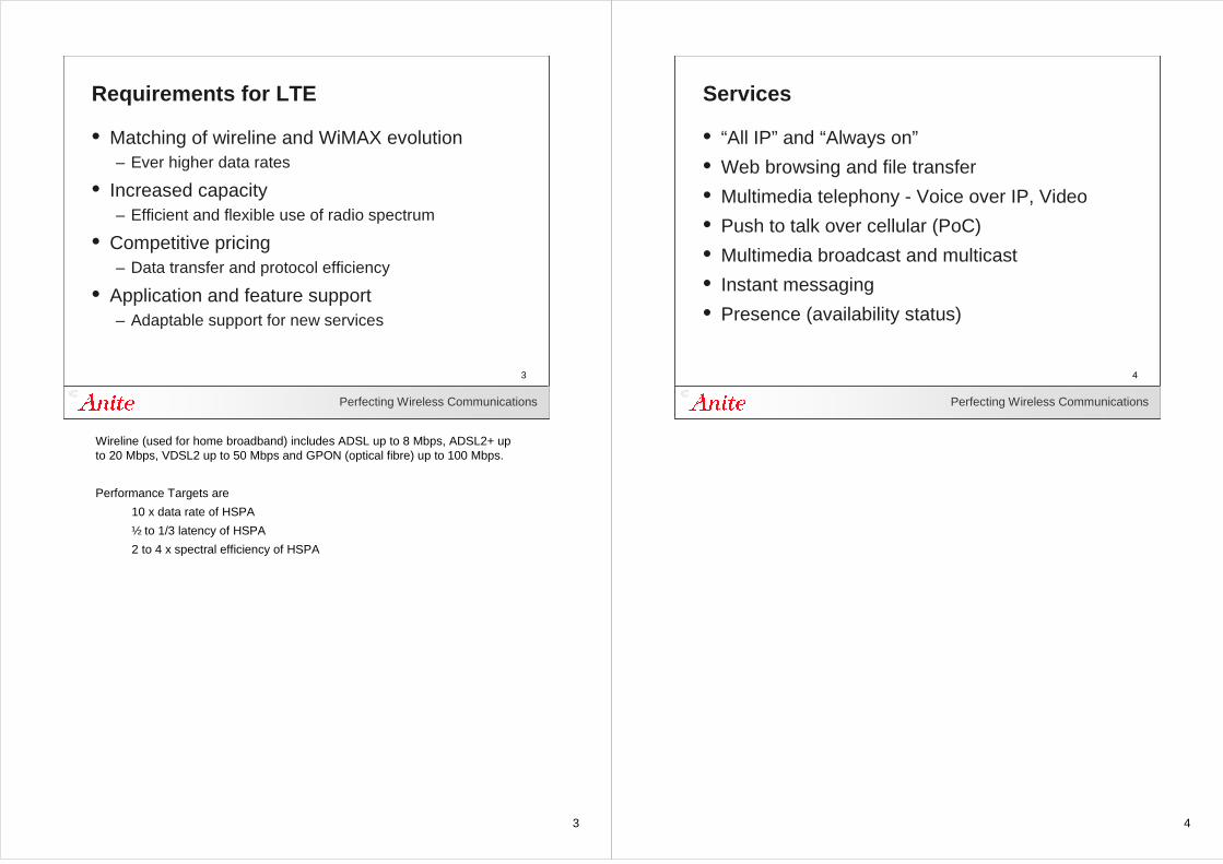
Requirements for LTE
• Matching of wireline and WiMAX evolution– Ever higher data rates
• Increased capacity– Efficient and flexible use of radio spectrum
• Competitive pricing – Data transfer and protocol efficiency
• Application and feature support– Adaptable support for new services
Wireline (used for home broadband) includes ADSL up to 8 Mbps, ADSL2+ upto 20 Mbps, VDSL2 up to 50 Mbps and GPON (optical fibre) up to 100 Mbps.
Performance Targets are
10 x data rate of HSPA
½ to 1/3 latency of HSPA
2 to 4 x spectral efficiency of HSPA
4
Perfecting Wireless Communications
4
Services
• “All IP” and “Always on”
• Web browsing and file transfer
• Multimedia telephony - Voice over IP, Video
• Push to talk over cellular (PoC)
• Multimedia broadcast and multicast
• Instant messaging
• Presence (availability status)
5
Perfecting Wireless Communications
5
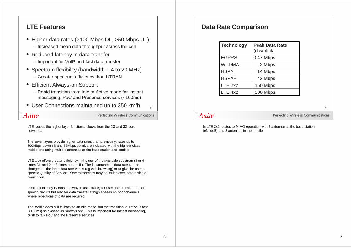
LTE Features
• Higher data rates (>100 Mbps DL, >50 Mbps UL)– Increased mean data throughput across the cell
• Reduced latency in data transfer– Important for VoIP and fast data transfer
• Spectrum flexibility (bandwidth 1.4 to 20 MHz)– Greater spectrum efficiency than UTRAN
• Efficient Always-on Support – Rapid transition from Idle to Active mode for Instant
messaging, PoC and Presence services (<100ms)
• User Connections maintained up to 350 km/h
LTE reuses the higher layer functional blocks from the 2G and 3G core networks.
The lower layers provide higher data rates than previously, rates up to 300Mbps downlink and 75Mbps uplink are indicated with the highest class mobile and using multiple antennas at the base station and mobile.
LTE also offers greater efficiency in the use of the available spectrum (3 or 4 times DL and 2 or 3 times better UL). The instantaneous data rate can be changed as the input data rate varies (eg web browsing) or to give the user a specific Quality of Service. Several services may be multiplexed onto a single connection.
Reduced latency (< 5ms one way in user plane) for user data is important for speech circuits but also for data transfer at high speeds on poor channels where repetitions of data are required.
The mobile does still fallback to an Idle mode, but the transition to Active is fast (<100ms) so classed as “Always on”. This is important for instant messaging, push to talk PoC and the Presence services
6
Perfecting Wireless Communications
6
Data Rate Comparison
300 MbpsLTE 4x2
150 MbpsLTE 2x2
42 MbpsHSPA+
14 MbpsHSPA
2 MbpsWCDMA
0.47 MbpsEGPRS
Peak Data Rate (downlink)
Technology
In LTE 2x2 relates to MIMO operation with 2 antennas at the base station (eNodeB) and 2 antennas in the mobile.
7
Perfecting Wireless Communications
7
Mobile Categories
QPSK16QAM64QAM
QPSK16QAM
ModulationUL
300/75 Mbps4x25
150/50 Mbps4
100/50 Mbps3
50/25 Mbps2x2
2
10/5 Mbps1x2
QPSK16QAM64QAM
1
Peak RateDL/UL
MIMODL
ModulationDL
Category
8
Perfecting Wireless Communications
8
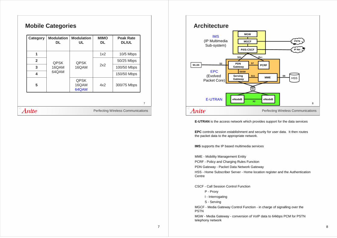
Architecture
P/I/S-CSCF
MGCF
MGW
PDN Gateway
PCRF
Serving Gateway
MME
eNodeB eNodeBX2
IMS(IP MultimediaSub-system)
EPC(Evolved
Packet Core)
E-UTRAN
S1
PSTN
IP Net
HSS
WLAN
S11
S7
S6
S2
SGi Rx+
S5/S8
E-UTRAN is the access network which provides support for the data services
EPC controls session establishment and security for user data. It then routes the packet data to the appropriate network.
IMS supports the IP based multimedia services
MME - Mobility Management Entity
PCRF - Policy and Charging Rules Function
PDN Gateway - Packet Data Network Gateway
HSS - Home Subscriber Server - Home location register and the Authentication Centre
CSCF - Call Session Control Function
P - Proxy
I - Interrogating
S - Serving
MGCF - Media Gateway Control Function - in charge of signalling over the PSTN
MGW - Media Gateway - conversion of VoIP data to 64kbps PCM for PSTN telephony network
9
Perfecting Wireless Communications
9
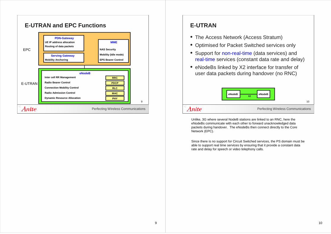
E-UTRAN and EPC Functions
EPC
E-UTRAN
Inter cell RR Management
Radio Bearer Control
Connection Mobility Control
Radio Admission Control
Dynamic Resource Allocation
RRC
PDCP
RLC
MAC
PHY
PDN-GatewayUE IP address allocation
Routing of data packets
Mobility Anchoring
Serving Gateway
eNodeB
MME
NAS Security
Mobility (Idle mode)
EPS Bearer Control
10
Perfecting Wireless Communications
10
E-UTRAN
• The Access Network (Access Stratum)
• Optimised for Packet Switched services only
• Support for non-real-time (data services) and real-time services (constant data rate and delay)
• eNodeBs linked by X2 interface for transfer of user data packets during handover (no RNC)
eNodeB eNodeBX2
Unlike, 3G where several NodeB stations are linked to an RNC, here the eNodeBs communicate with each other to forward unacknowledged data packets during handover. The eNodeBs then connect directly to the Core Network (EPC).
Since there is no support for Circuit Switched services, the PS domain must be able to support real time services by ensuring that it provide a constant data rate and delay for speech or video telephony calls.
11
Perfecting Wireless Communications
11
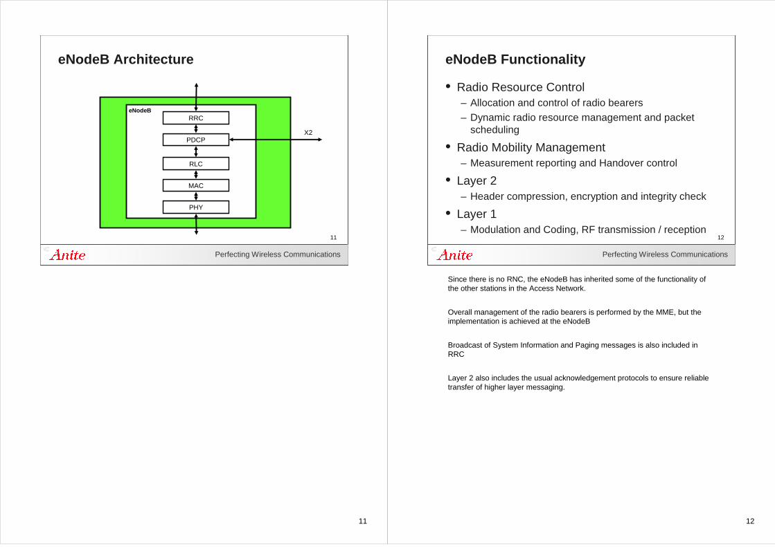
eNodeB Architecture
eNodeBRRC
PDCP
RLC
MAC
PHY
X2
12
Perfecting Wireless Communications
12
eNodeB Functionality
• Radio Resource Control – Allocation and control of radio bearers– Dynamic radio resource management and packet
scheduling
• Radio Mobility Management – Measurement reporting and Handover control
• Layer 2 – Header compression, encryption and integrity check
• Layer 1– Modulation and Coding, RF transmission / reception
Since there is no RNC, the eNodeB has inherited some of the functionality of the other stations in the Access Network.
Overall management of the radio bearers is performed by the MME, but the implementation is achieved at the eNodeB
Broadcast of System Information and Paging messages is also included in RRC
Layer 2 also includes the usual acknowledgement protocols to ensure reliable transfer of higher layer messaging.
13
Perfecting Wireless Communications
13
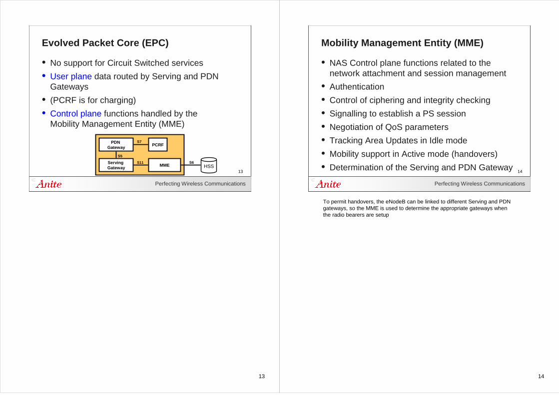
Evolved Packet Core (EPC)
• No support for Circuit Switched services
• User plane data routed by Serving and PDN Gateways
• (PCRF is for charging)
• Control plane functions handled by the Mobility Management Entity (MME)
PDN Gateway
PCRF
Serving Gateway
MMES11
S7
S5
HSSS6
14
Perfecting Wireless Communications
14
Mobility Management Entity (MME)
• NAS Control plane functions related to the network attachment and session management
• Authentication
• Control of ciphering and integrity checking
• Signalling to establish a PS session
• Negotiation of QoS parameters
• Tracking Area Updates in Idle mode
• Mobility support in Active mode (handovers)
• Determination of the Serving and PDN Gateway
To permit handovers, the eNodeB can be linked to different Serving and PDN gateways, so the MME is used to determine the appropriate gateways when the radio bearers are setup
15
Perfecting Wireless Communications
15
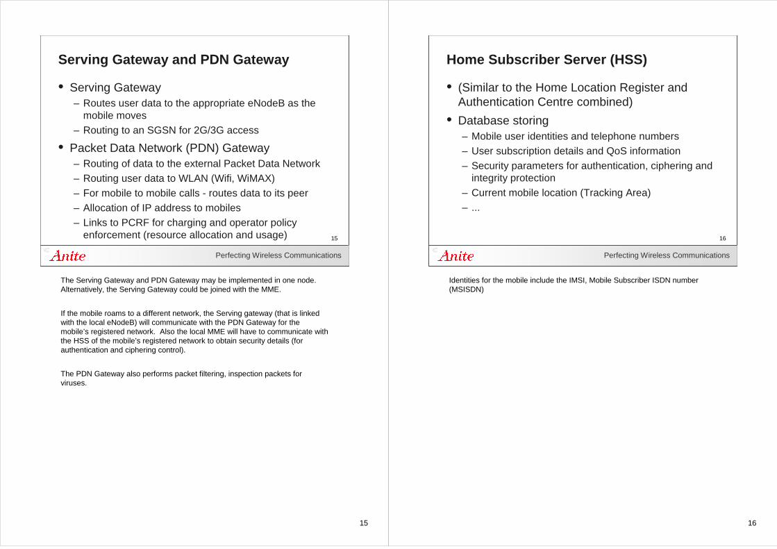
Serving Gateway and PDN Gateway
• Serving Gateway– Routes user data to the appropriate eNodeB as the
mobile moves– Routing to an SGSN for 2G/3G access
• Packet Data Network (PDN) Gateway– Routing of data to the external Packet Data Network– Routing user data to WLAN (Wifi, WiMAX)– For mobile to mobile calls - routes data to its peer– Allocation of IP address to mobiles– Links to PCRF for charging and operator policy
enforcement (resource allocation and usage)
The Serving Gateway and PDN Gateway may be implemented in one node. Alternatively, the Serving Gateway could be joined with the MME.
If the mobile roams to a different network, the Serving gateway (that is linked with the local eNodeB) will communicate with the PDN Gateway for the mobile’s registered network. Also the local MME will have to communicate with the HSS of the mobile’s registered network to obtain security details (for authentication and ciphering control).
The PDN Gateway also performs packet filtering, inspection packets for viruses.
16
Perfecting Wireless Communications
16
Home Subscriber Server (HSS)
• (Similar to the Home Location Register and Authentication Centre combined)
• Database storing– Mobile user identities and telephone numbers– User subscription details and QoS information– Security parameters for authentication, ciphering and
integrity protection– Current mobile location (Tracking Area)– ...
Identities for the mobile include the IMSI, Mobile Subscriber ISDN number (MSISDN)
17
Perfecting Wireless Communications
17
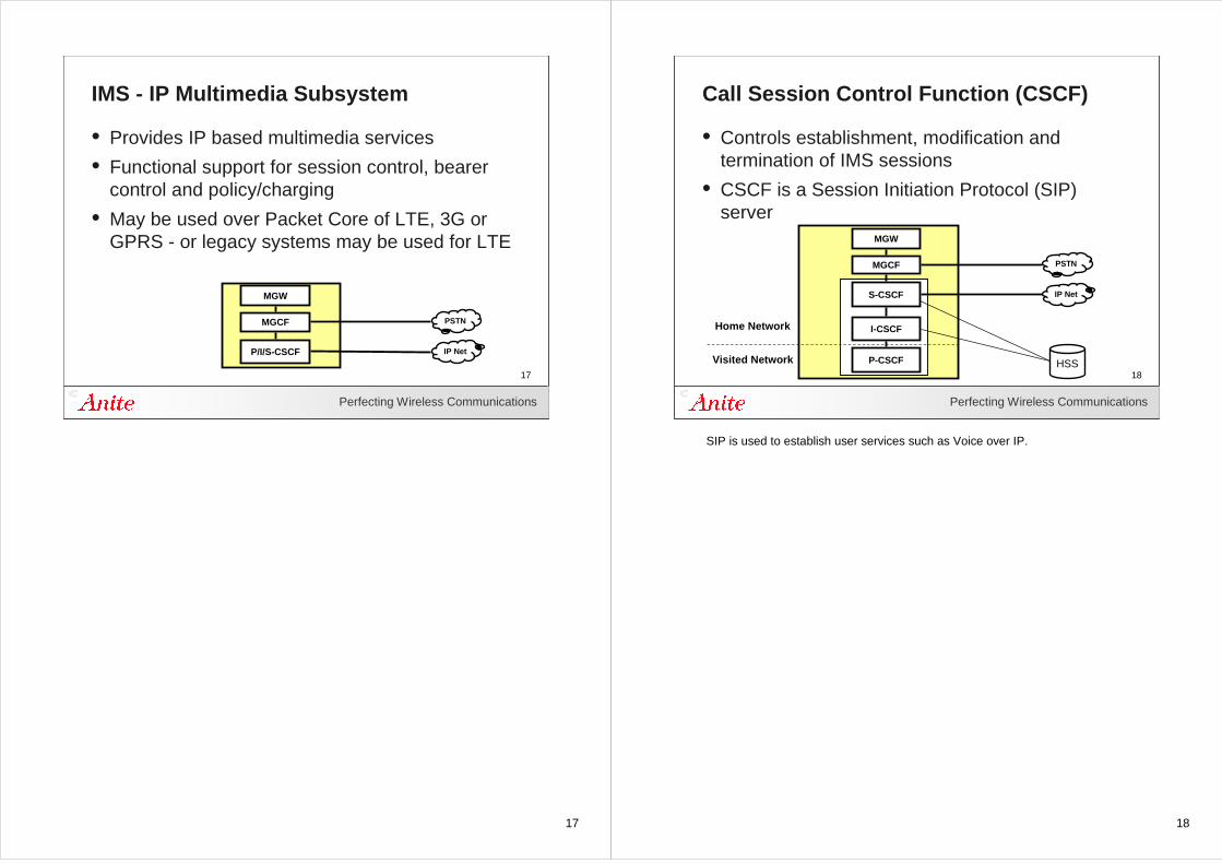
IMS - IP Multimedia Subsystem
• Provides IP based multimedia services
• Functional support for session control, bearer control and policy/charging
• May be used over Packet Core of LTE, 3G or GPRS - or legacy systems may be used for LTE
P/I/S-CSCF
MGCF
MGW
PSTN
IP Net
18
Perfecting Wireless Communications
18
Call Session Control Function (CSCF)
• Controls establishment, modification and termination of IMS sessions
• CSCF is a Session Initiation Protocol (SIP) server
S-CSCF
MGCF
MGW
PSTN
IP Net
I-CSCF
P-CSCF
Home Network
Visited Network HSS
SIP is used to establish user services such as Voice over IP.
19
Perfecting Wireless Communications
19
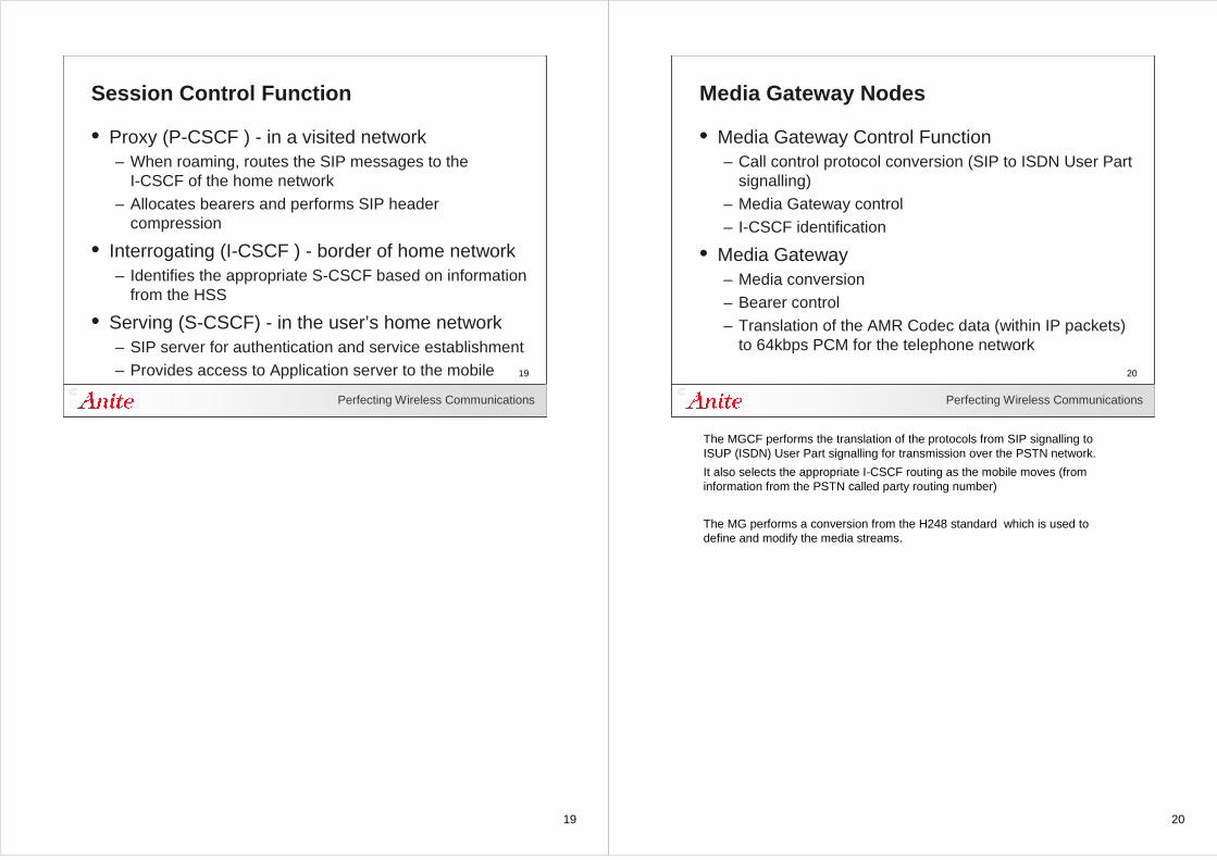
Session Control Function
• Proxy (P-CSCF ) - in a visited network– When roaming, routes the SIP messages to the
I-CSCF of the home network– Allocates bearers and performs SIP header
compression
• Interrogating (I-CSCF ) - border of home network– Identifies the appropriate S-CSCF based on information
from the HSS
• Serving (S-CSCF) - in the user’s home network– SIP server for authentication and service establishment– Provides access to Application server to the mobile
20
Perfecting Wireless Communications
20
Media Gateway Nodes
• Media Gateway Control Function– Call control protocol conversion (SIP to ISDN User Part
signalling)– Media Gateway control– I-CSCF identification
• Media Gateway– Media conversion– Bearer control– Translation of the AMR Codec data (within IP packets)
to 64kbps PCM for the telephone network
The MGCF performs the translation of the protocols from SIP signalling to ISUP (ISDN) User Part signalling for transmission over the PSTN network.
It also selects the appropriate I-CSCF routing as the mobile moves (from information from the PSTN called party routing number)
The MG performs a conversion from the H248 standard which is used to define and modify the media streams.
21
Perfecting Wireless Communications
21
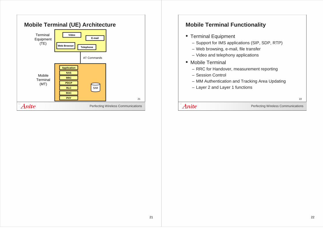
Mobile Terminal (UE) Architecture
Web Browser
Video
Telephone
Terminal Equipment
(TE)
MobileTerminal
(MT)SIM
AT Commands
RRC
PDCP
RLC
MAC
PHY
NAS
Application
22
Perfecting Wireless Communications
22
Mobile Terminal Functionality
• Terminal Equipment– Support for IMS applications (SIP, SDP, RTP)– Web browsing, e-mail, file transfer– Video and telephony applications
• Mobile Terminal– RRC for Handover, measurement reporting– Session Control– MM Authentication and Tracking Area Updating– Layer 2 and Layer 1 functions
23
Perfecting Wireless Communications
23
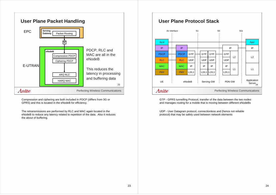
User Plane Packet Handling
Serving Gateway
eNodeB
EPC
E-UTRAN
S1
Packet Routing
Compression PDCP
Ciphering PDCP
ARQ RLC
HARQ MAC
PDCP, RLC and MAC are all in the eNodeB
This reduces the latency in processing and buffering data
Compression and ciphering are both included in PDCP (differs from 3G or GPRS) and this is located in the eNodeB for efficiency.
The retransmissions are performed by RLC and MAC again located in the eNodeB to reduce any latency related to repetition of the data. Also it reduces the about of buffering.
24
Perfecting Wireless Communications
24
User Plane Protocol Stack
PHY
MAC
RLC
PDCP
IP
PHY
MAC
RLC
PDCP
IP
L2/L1
IP
UDP
Appl
IP
UE eNodeBApplication
ServerServing GW
GTP
L1
L2
IP
L2/L1
IP
UDP
GTP
L2/L1
IP
UDP
GTP
L2/L1
IP
UDP
GTP
L1
L2
Appl
PDN GW
Air interface S1 S5 SGi
GTP - GPRS tunnelling Protocol, transfer of the data between the two nodes and manages routing for a mobile that is moving between different eNodeBs
UDP - User Datagram protocol, connectionless and (hence not reliable protocol) that may be safely used between network elements
25
Perfecting Wireless Communications
25
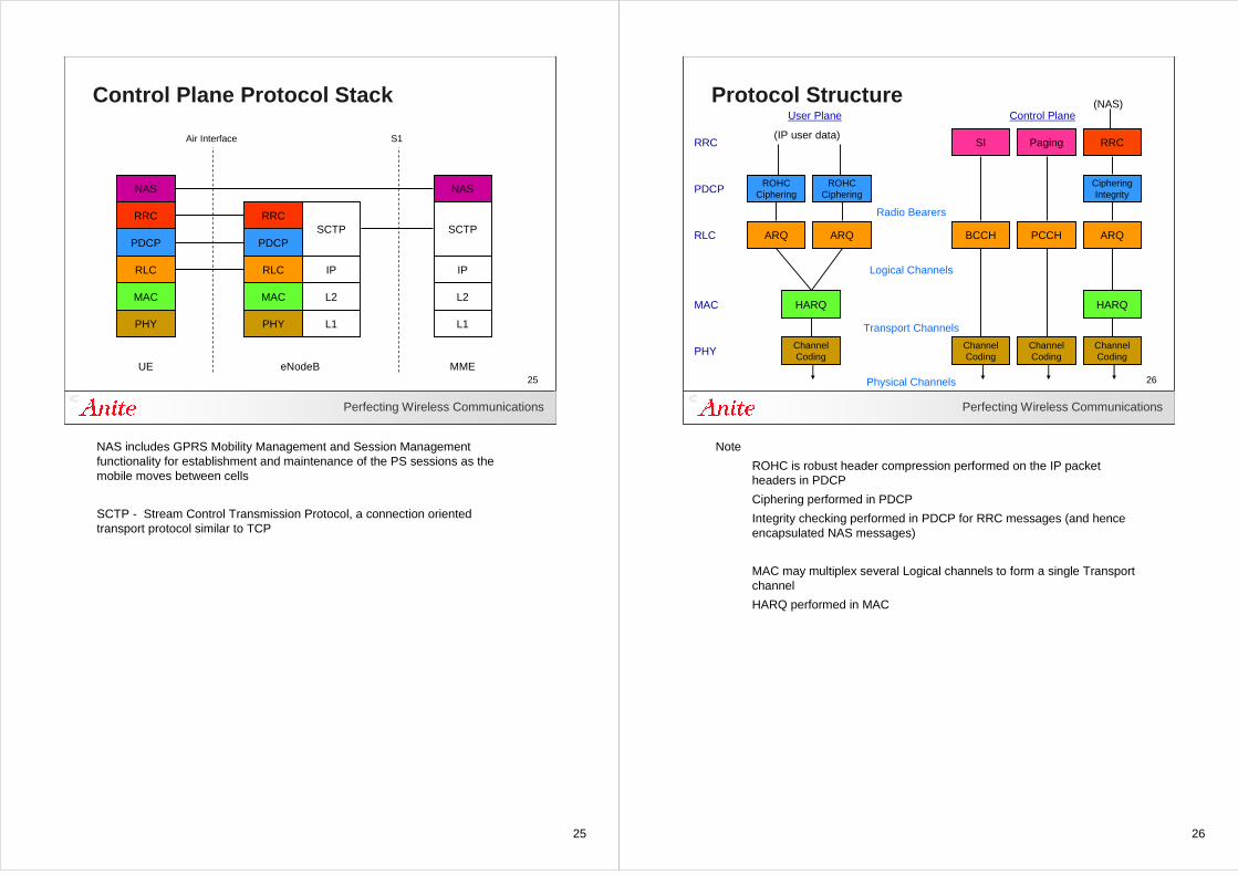
Control Plane Protocol Stack
PHY
MAC
RLC
PDCP
RRC
NAS
PHY
MAC
RLC
PDCP
RRC
L1
L2
IP
SCTP
NAS
L1
L2
IP
SCTP
UE eNodeB MME
Air Interface S1
NAS includes GPRS Mobility Management and Session Management functionality for establishment and maintenance of the PS sessions as the mobile moves between cells
SCTP - Stream Control Transmission Protocol, a connection oriented transport protocol similar to TCP
26
Perfecting Wireless Communications
26
Protocol Structure
ChannelCoding
HARQ
ARQ
ROHCCiphering
RRC
PDCP
ChannelCoding
ChannelCoding
ChannelCoding
HARQ
ARQ ARQBCCH PCCH
ROHCCiphering
CipheringIntegrity
PagingSI
MAC
RLC
PHY
RRC
Radio Bearers
Logical Channels
Transport Channels
Physical Channels
User Plane Control Plane(NAS)
(IP user data)
Note
ROHC is robust header compression performed on the IP packet headers in PDCP
Ciphering performed in PDCP
Integrity checking performed in PDCP for RRC messages (and henceencapsulated NAS messages)
MAC may multiplex several Logical channels to form a single Transport channel
HARQ performed in MAC
27
27Perfecting Wireless Communications
27
Physical layer
28
Perfecting Wireless Communications
28
Channel Types
PHY
MAC
RLC
Logical Channels
Transport Channels
Physical Channels
Radio Link
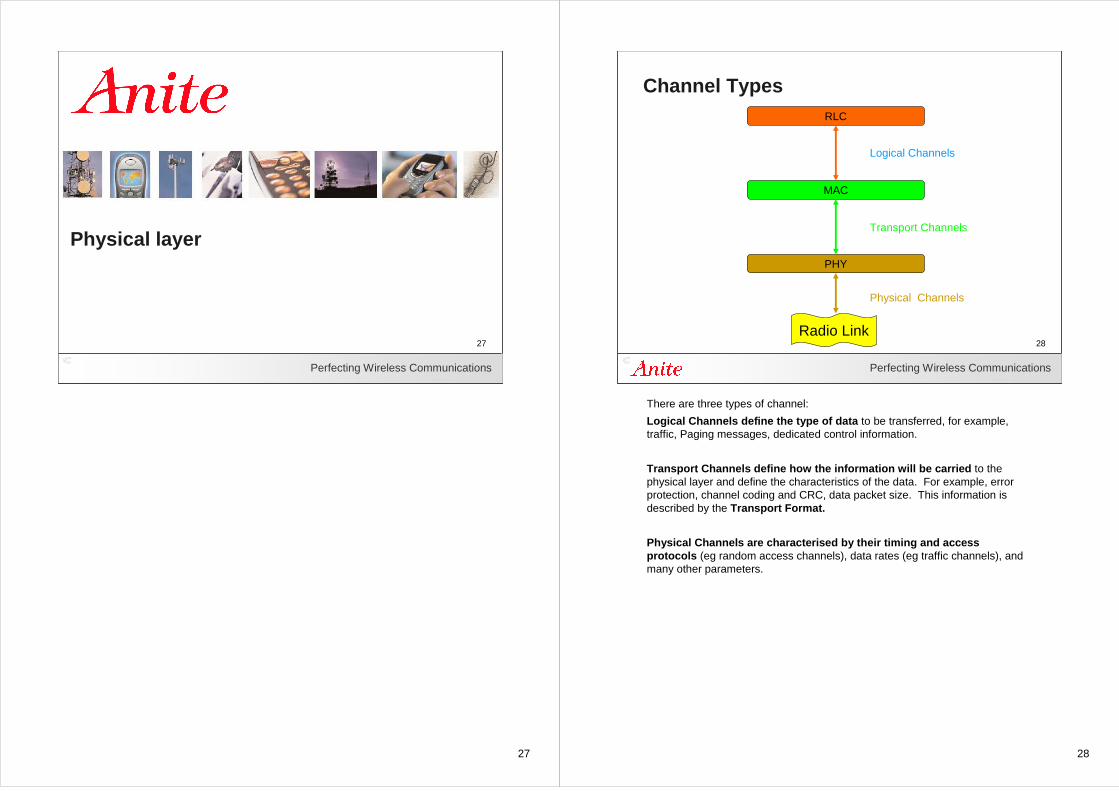
There are three types of channel:
Logical Channels define the type of data to be transferred, for example, traffic, Paging messages, dedicated control information.
Transport Channels define how the information will be carried to the physical layer and define the characteristics of the data. For example, error protection, channel coding and CRC, data packet size. This information is described by the Transport Format.
Physical Channels are characterised by their timing and access protocols (eg random access channels), data rates (eg traffic channels), and many other parameters.
29
Perfecting Wireless Communications
29
Physical Layer - Requirements
• Peak data rates DL - 100Mbps UL - 50Mbps
• Variable bandwidth 1.4, 3, 5, 10, 15, 20 MHz
• Improved spectrum efficiency (4 x UTRAN in DL)
• Reduced delay - RRC idle to active state
• Reduced transmission latency < 5ms
• Support for high mobile speeds - 350km/h(but best data rates achieved at low speeds)
30
Perfecting Wireless Communications
30
Physical Layer - Functionality
• CRC insertion - for detection of channel errors
• Channel coding for error protection
• Channel interleaving
• Modulation QPSK, 16QAM, 64 QAM
• Mapping to resources and antenna ports
Several Transport channels may be multiplexed to be transmitted on the same physical channel (or if the data rate is high, several physical channels)
Data is given a CRC then forward error protected and interleaved. Errors received via the channel may then be corrected and identified.
31
31Perfecting Wireless Communications
31
E-UTRA Physical layer
32
Perfecting Wireless Communications
32
Comparison of Spectrum Usage
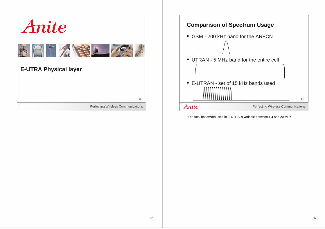
• GSM - 200 kHz band for the ARFCN
• UTRAN - 5 MHz band for the entire cell
• E-UTRAN - set of 15 kHz bands used
The total bandwidth used in E-UTRA is variable between 1.4 and 20 MHz
33
Perfecting Wireless Communications
33
Physical Channel Sharing
• Downlink OFDMA
• Uplink SC-FDMA
C B A
frequency
frequency
34
Perfecting Wireless Communications
34
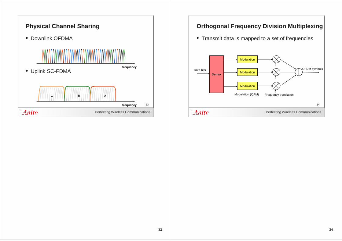
Orthogonal Frequency Division Multiplexing
• Transmit data is mapped to a set of frequencies
Demux
Modulation
Modulation
Modulation
Data bits OFDM symbols
Frequency translationModulation (QAM)
35
Perfecting Wireless Communications
35
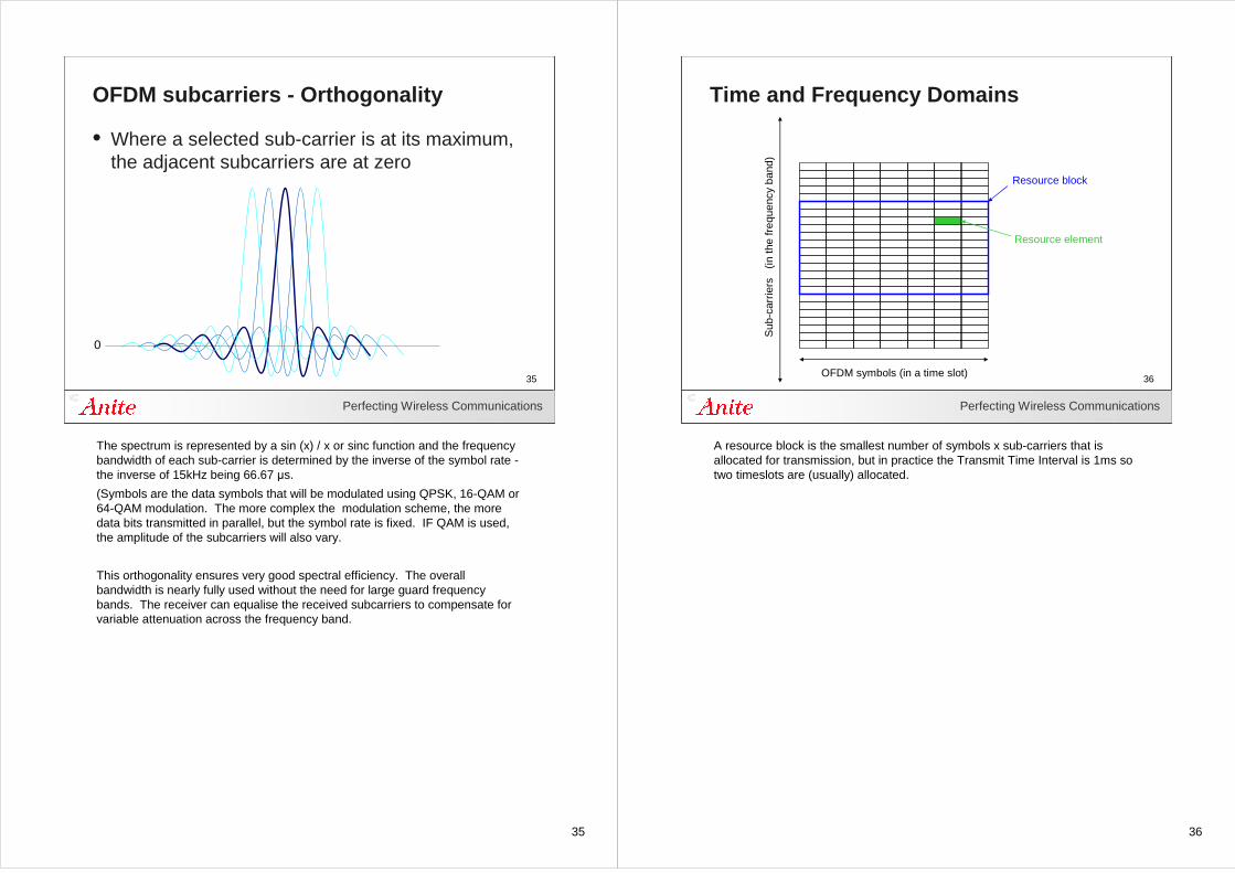
OFDM subcarriers - Orthogonality
• Where a selected sub-carrier is at its maximum, the adjacent subcarriers are at zero
0
The spectrum is represented by a sin (x) / x or sinc function and the frequency bandwidth of each sub-carrier is determined by the inverse of the symbol rate -the inverse of 15kHz being 66.67 µs.
(Symbols are the data symbols that will be modulated using QPSK, 16-QAM or 64-QAM modulation. The more complex the modulation scheme, the more data bits transmitted in parallel, but the symbol rate is fixed. IF QAM is used, the amplitude of the subcarriers will also vary.
This orthogonality ensures very good spectral efficiency. The overall bandwidth is nearly fully used without the need for large guard frequency bands. The receiver can equalise the received subcarriers to compensate for variable attenuation across the frequency band.
36
Perfecting Wireless Communications
36
Time and Frequency Domains
Sub
-car
riers
(in
the
freq
uenc
y ba
nd)
OFDM symbols (in a time slot)
Resource block
Resource element
A resource block is the smallest number of symbols x sub-carriers that is allocated for transmission, but in practice the Transmit Time Interval is 1ms so two timeslots are (usually) allocated.
37
Perfecting Wireless Communications
37
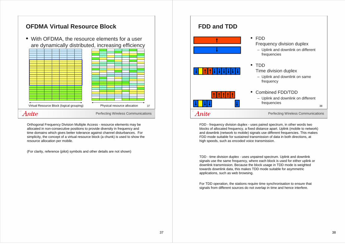
OFDMA Virtual Resource Block
Virtual Resource Block (logical grouping) Physical resource allocation
• With OFDMA, the resource elements for a user are dynamically distributed, increasing efficiency
Orthogonal Frequency Division Multiple Access - resource elements may be allocated in non-consecutive positions to provide diversity in frequency and time domains which gives better tolerance against channel disturbances. For simplicity, the concept of a virtual resource block (a chunk) is used to show the resource allocation per mobile.
(For clarity, reference (pilot) symbols and other details are not shown)
38
Perfecting Wireless Communications
38
FDD and TDD
• FDD Frequency division duplex– Uplink and downlink on different
frequencies
• TDD Time division duplex– Uplink and downlink on same
frequency
• Combined FDD/TDD– Uplink and downlink on different
frequencies
FDD - frequency division duplex - uses paired spectrum, in other words two blocks of allocated frequency, a fixed distance apart. Uplink (mobile to network) and downlink (network to mobile) signals use different frequencies. This makes FDD mode suitable for sustained transmission of data in both directions, at high speeds, such as encoded voice transmission.
TDD - time division duplex - uses unpaired spectrum. Uplink and downlink signals use the same frequency, where each block is used for either uplink or downlink transmission. Because the block usage in TDD mode is weighted towards downlink data, this makes TDD mode suitable for asymmetric applications, such as web browsing.
For TDD operation, the stations require time synchronisation to ensure that signals from different sources do not overlap in time and hence interfere.
39
Perfecting Wireless Communications
39
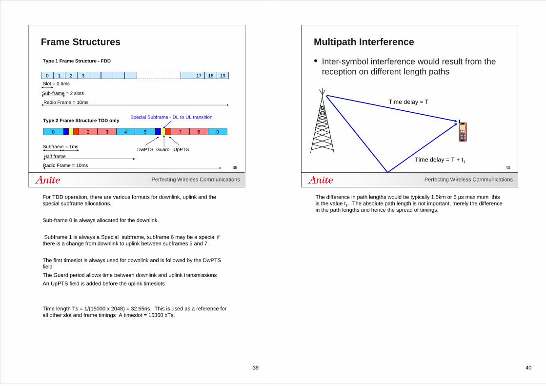
Frame Structures
0 1 2 3 17 18 19
Slot = 0.5ms
Sub-frame = 2 slots
Radio Frame = 10ms
Type 1 Frame Structure - FDD
0
Subframe = 1ms
Half frame
Radio Frame = 10ms
Type 2 Frame Structure TDD only
2
DwPTS Guard UpPTS
3 4 5 7 8 9
Special Subframe - DL to UL transition
For TDD operation, there are various formats for downlink, uplink and the special subframe allocations.
Sub-frame 0 is always allocated for the downlink.
Subframe 1 is always a Special subframe, subframe 6 may be a special if there is a change from downlink to uplink between subframes 5 and 7.
The first timeslot is always used for downlink and is followed by the DwPTS field
The Guard period allows time between downlink and uplink transmissions
An UpPTS field is added before the uplink timeslots
Time length Ts = 1/(15000 x 2048) = 32.55ns. This is used as a reference for all other slot and frame timings A timeslot = 15360 xTs.
40
Perfecting Wireless Communications
40
Multipath Interference
• Inter-symbol interference would result from the reception on different length paths
Time delay = T
Time delay = T + t1
The difference in path lengths would be typically 1.5km or 5 µs maximum this is the value t1. The absolute path length is not important, merely the difference in the path lengths and hence the spread of timings.
41
Perfecting Wireless Communications
41
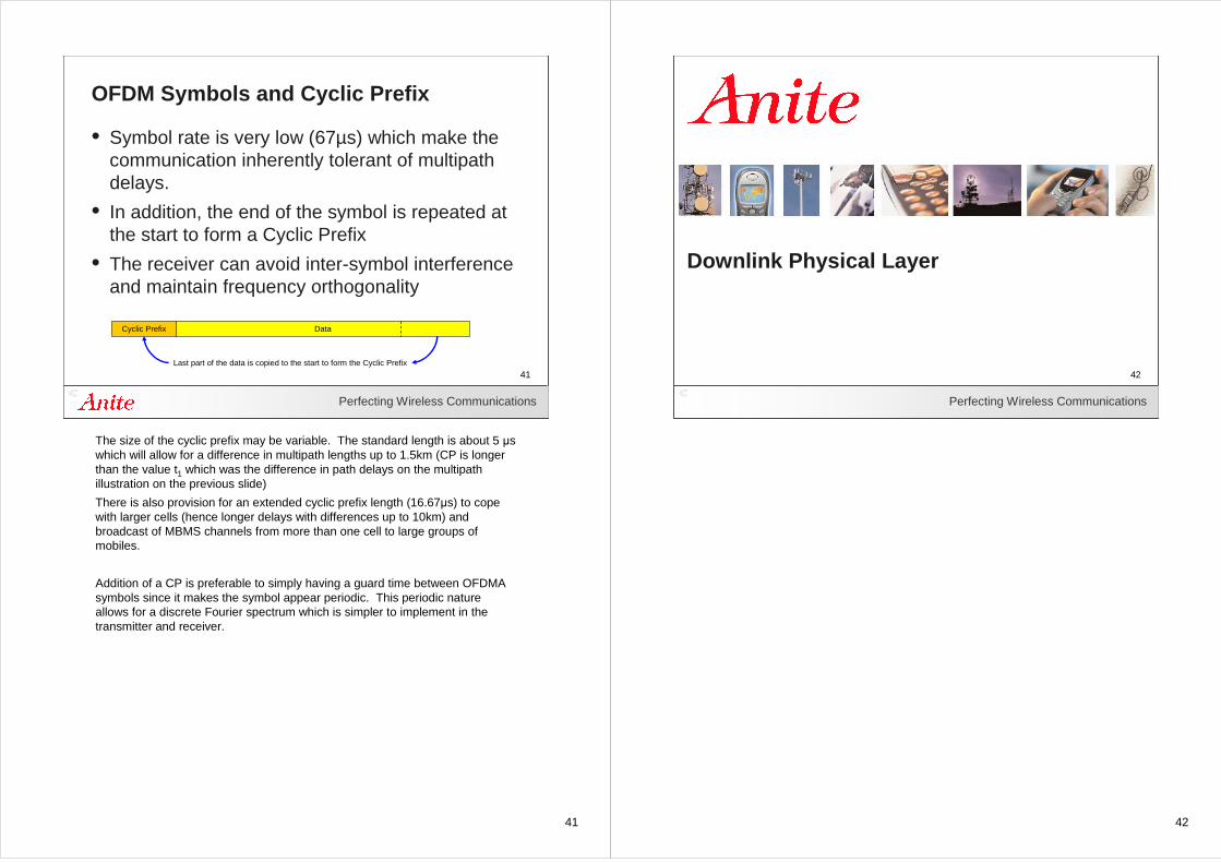
OFDM Symbols and Cyclic Prefix
• Symbol rate is very low (67µs) which make the communication inherently tolerant of multipath delays.
• In addition, the end of the symbol is repeated at the start to form a Cyclic Prefix
• The receiver can avoid inter-symbol interference and maintain frequency orthogonality
Cyclic Prefix Data
Last part of the data is copied to the start to form the Cyclic Prefix
The size of the cyclic prefix may be variable. The standard length is about 5 µs which will allow for a difference in multipath lengths up to 1.5km (CP is longer than the value t1 which was the difference in path delays on the multipath illustration on the previous slide)
There is also provision for an extended cyclic prefix length (16.67µs) to cope with larger cells (hence longer delays with differences up to 10km) and broadcast of MBMS channels from more than one cell to large groups of mobiles.
Addition of a CP is preferable to simply having a guard time between OFDMA symbols since it makes the symbol appear periodic. This periodic nature allows for a discrete Fourier spectrum which is simpler to implement in the transmitter and receiver.
42
42Perfecting Wireless Communications
42
Downlink Physical Layer
43
Perfecting Wireless Communications
43
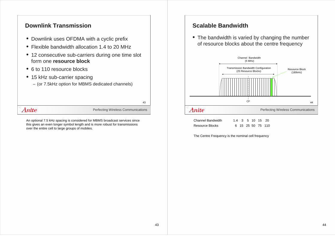
Downlink Transmission
• Downlink uses OFDMA with a cyclic prefix
• Flexible bandwidth allocation 1.4 to 20 MHz
• 12 consecutive sub-carriers during one time slot form one resource block
• 6 to 110 resource blocks
• 15 kHz sub-carrier spacing – (or 7.5kHz option for MBMS dedicated channels)
An optional 7.5 kHz spacing is considered for MBMS broadcast services since this gives an even longer symbol length and is more robust for transmissions over the entire cell to large groups of mobiles.
44
Perfecting Wireless Communications
44
Scalable Bandwidth
• The bandwidth is varied by changing the number of resource blocks about the centre frequency
CF
Transmission Bandwidth Configuration(25 Resource Blocks)
Channel Bandwidth (5 MHz)
Resource Block(180kHz)
Channel Bandwidth 1.4 3 5 10 15 20
Resource Blocks 6 15 25 50 75 110
The Centre Frequency is the nominal cell frequency
45
Perfecting Wireless Communications
45
Downlink Resource BlockS
ub-c
arrie
rs
(in th
e fr
eque
ncy
band
)
[7] OFDM symbols (in a time slot)
Resource block
Resource element
[12]
Sub
-car
riers
in th
e re
sour
ce b
lock
(18
0 kH
z)
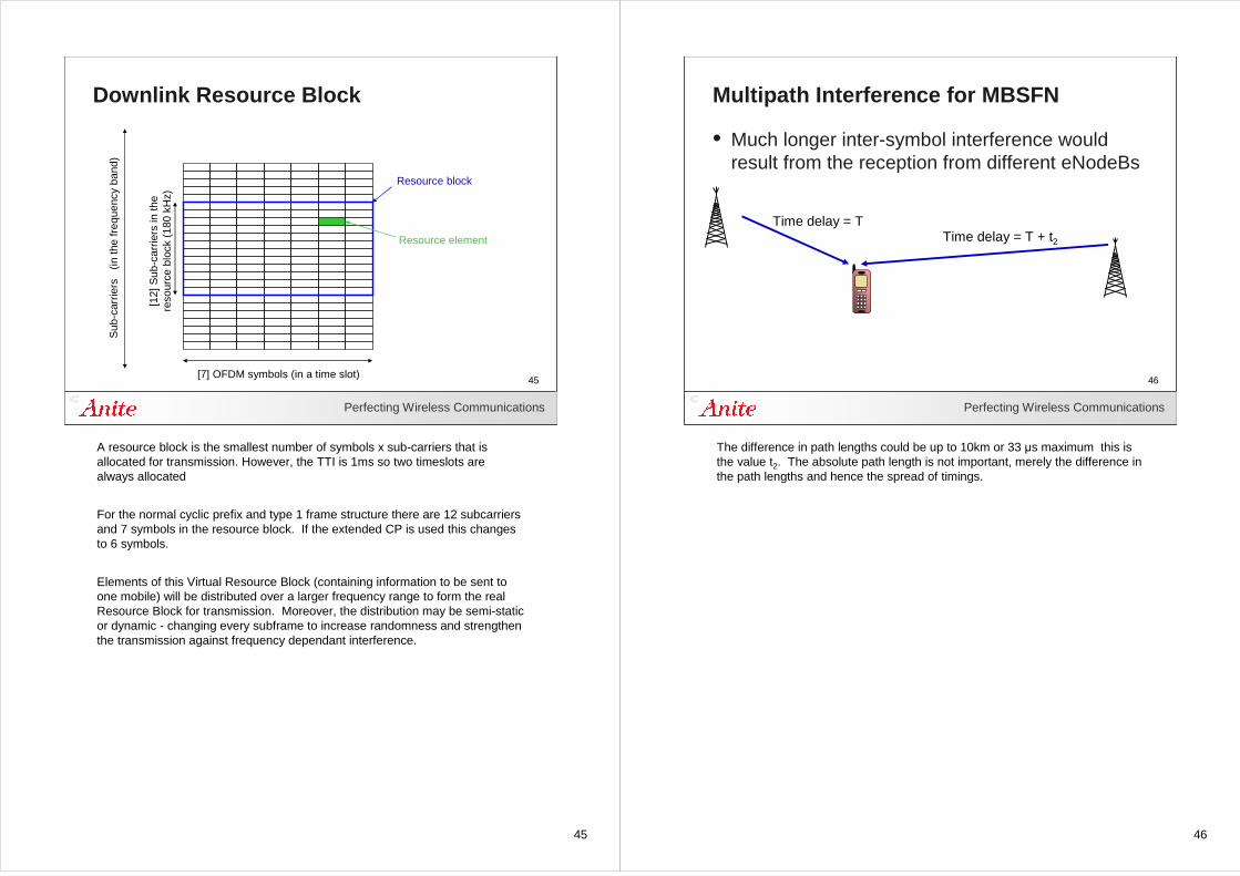
A resource block is the smallest number of symbols x sub-carriers that is allocated for transmission. However, the TTI is 1ms so two timeslots are always allocated
For the normal cyclic prefix and type 1 frame structure there are 12 subcarriers and 7 symbols in the resource block. If the extended CP is used this changes to 6 symbols.
Elements of this Virtual Resource Block (containing information to be sent to one mobile) will be distributed over a larger frequency range to form the real Resource Block for transmission. Moreover, the distribution may be semi-static or dynamic - changing every subframe to increase randomness and strengthen the transmission against frequency dependant interference.
46
Perfecting Wireless Communications
46
Multipath Interference for MBSFN
• Much longer inter-symbol interference would result from the reception from different eNodeBs
Time delay = TTime delay = T + t2
The difference in path lengths could be up to 10km or 33 µs maximum this is the value t2. The absolute path length is not important, merely the difference in the path lengths and hence the spread of timings.
47
Perfecting Wireless Communications
47
Downlink Resource Block for MBSFNS
ub-c
arrie
rs
(in th
e fr
eque
ncy
band
)
3 OFDM symbols (in a time slot)
Resource block
Resource element
24 S
ub-c
arrie
rs in
the
reso
urce
blo
ck (
180
kHz)
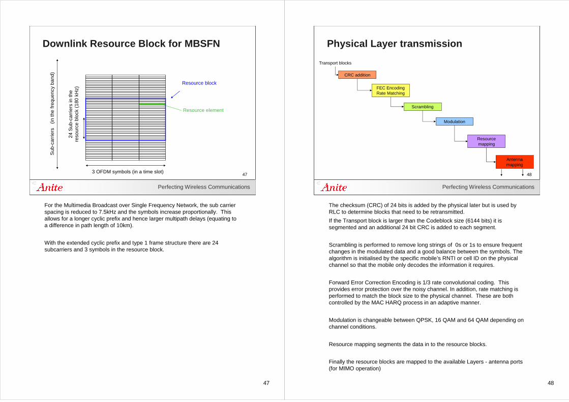
For the Multimedia Broadcast over Single Frequency Network, the sub carrier spacing is reduced to 7.5kHz and the symbols increase proportionally. This allows for a longer cyclic prefix and hence larger multipath delays (equating to a difference in path length of 10km).
With the extended cyclic prefix and type 1 frame structure there are 24 subcarriers and 3 symbols in the resource block.
48
Perfecting Wireless Communications
48
Physical Layer transmission
CRC addition
FEC EncodingRate Matching
Scrambling
Modulation
Resource mapping
Transport blocks
Antenna mapping
The checksum (CRC) of 24 bits is added by the physical later but is used by RLC to determine blocks that need to be retransmitted.
If the Transport block is larger than the Codeblock size (6144 bits) it is segmented and an additional 24 bit CRC is added to each segment.
Scrambling is performed to remove long strings of 0s or 1s to ensure frequent changes in the modulated data and a good balance between the symbols. The algorithm is initialised by the specific mobile’s RNTI or cell ID on the physical channel so that the mobile only decodes the information it requires.
Forward Error Correction Encoding is 1/3 rate convolutional coding. This provides error protection over the noisy channel. In addition, rate matching is performed to match the block size to the physical channel. These are both controlled by the MAC HARQ process in an adaptive manner.
Modulation is changeable between QPSK, 16 QAM and 64 QAM depending on channel conditions.
Resource mapping segments the data in to the resource blocks.
Finally the resource blocks are mapped to the available Layers - antenna ports (for MIMO operation)
49
Perfecting Wireless Communications
49
CRC Attachment
Transport Block CRC
Code Block
Transport Block (MAC SDU)
CRC Code Block CRC CRC
[24] bit CRC added
If Transport Block is greater than 6144 bitsit is segmented and an additional [24] bit CRC is added to each Code Block
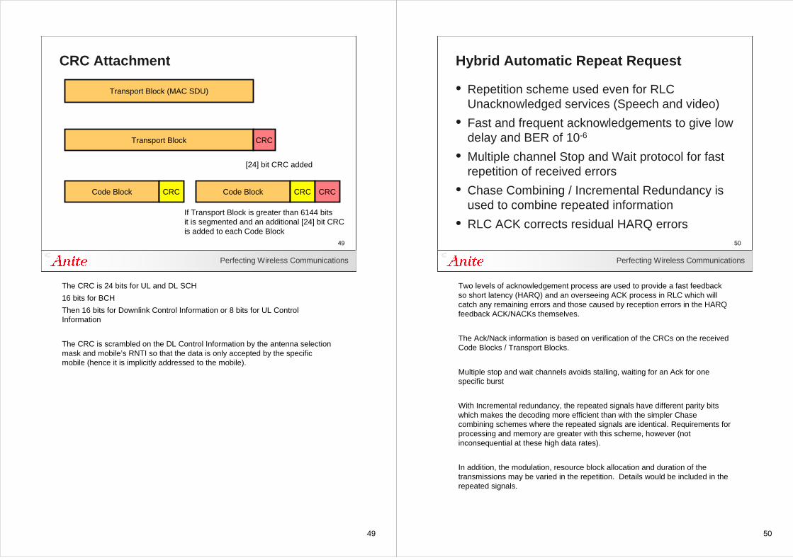
The CRC is 24 bits for UL and DL SCH
16 bits for BCH
Then 16 bits for Downlink Control Information or 8 bits for UL Control Information
The CRC is scrambled on the DL Control Information by the antenna selection mask and mobile’s RNTI so that the data is only accepted by the specific mobile (hence it is implicitly addressed to the mobile).
50
Perfecting Wireless Communications
50
Hybrid Automatic Repeat Request
• Repetition scheme used even for RLC Unacknowledged services (Speech and video)
• Fast and frequent acknowledgements to give low delay and BER of 10-6
• Multiple channel Stop and Wait protocol for fast repetition of received errors
• Chase Combining / Incremental Redundancy is used to combine repeated information
• RLC ACK corrects residual HARQ errors
Two levels of acknowledgement process are used to provide a fast feedback so short latency (HARQ) and an overseeing ACK process in RLC which will catch any remaining errors and those caused by reception errors in the HARQ feedback ACK/NACKs themselves.
The Ack/Nack information is based on verification of the CRCs on the received Code Blocks / Transport Blocks.
Multiple stop and wait channels avoids stalling, waiting for an Ack for one specific burst
With Incremental redundancy, the repeated signals have different parity bits which makes the decoding more efficient than with the simpler Chase combining schemes where the repeated signals are identical. Requirements for processing and memory are greater with this scheme, however (notinconsequential at these high data rates).
In addition, the modulation, resource block allocation and duration of the transmissions may be varied in the repetition. Details would be included in the repeated signals.
51
Perfecting Wireless Communications
51
Hybrid-ARQ Example
Data Data Data Data
Ack Ack
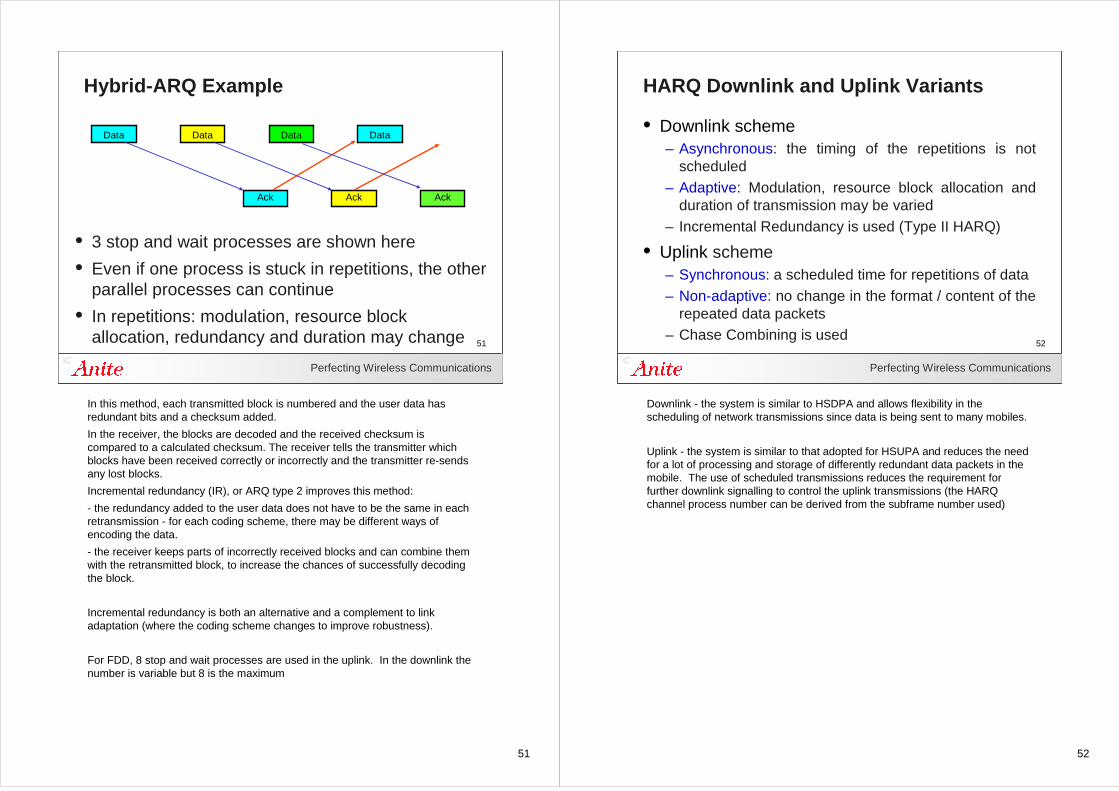
• 3 stop and wait processes are shown here
• Even if one process is stuck in repetitions, the other parallel processes can continue
• In repetitions: modulation, resource block allocation, redundancy and duration may change
Ack
In this method, each transmitted block is numbered and the user data has redundant bits and a checksum added.
In the receiver, the blocks are decoded and the received checksum is compared to a calculated checksum. The receiver tells the transmitter which blocks have been received correctly or incorrectly and the transmitter re-sends any lost blocks.
Incremental redundancy (IR), or ARQ type 2 improves this method:
- the redundancy added to the user data does not have to be the same in each retransmission - for each coding scheme, there may be different ways of encoding the data.
- the receiver keeps parts of incorrectly received blocks and can combine them with the retransmitted block, to increase the chances of successfully decoding the block.
Incremental redundancy is both an alternative and a complement to link adaptation (where the coding scheme changes to improve robustness).
For FDD, 8 stop and wait processes are used in the uplink. In the downlink the number is variable but 8 is the maximum
52
Perfecting Wireless Communications
52
HARQ Downlink and Uplink Variants
• Downlink scheme– Asynchronous: the timing of the repetitions is not
scheduled– Adaptive: Modulation, resource block allocation and
duration of transmission may be varied– Incremental Redundancy is used (Type II HARQ)
• Uplink scheme– Synchronous: a scheduled time for repetitions of data– Non-adaptive: no change in the format / content of the
repeated data packets– Chase Combining is used
Downlink - the system is similar to HSDPA and allows flexibility in the scheduling of network transmissions since data is being sent to many mobiles.
Uplink - the system is similar to that adopted for HSUPA and reduces the need for a lot of processing and storage of differently redundant data packets in the mobile. The use of scheduled transmissions reduces the requirement for further downlink signalling to control the uplink transmissions (the HARQ channel process number can be derived from the subframe number used)
53
Perfecting Wireless Communications
53
Incremental Redundancy (Downlink)
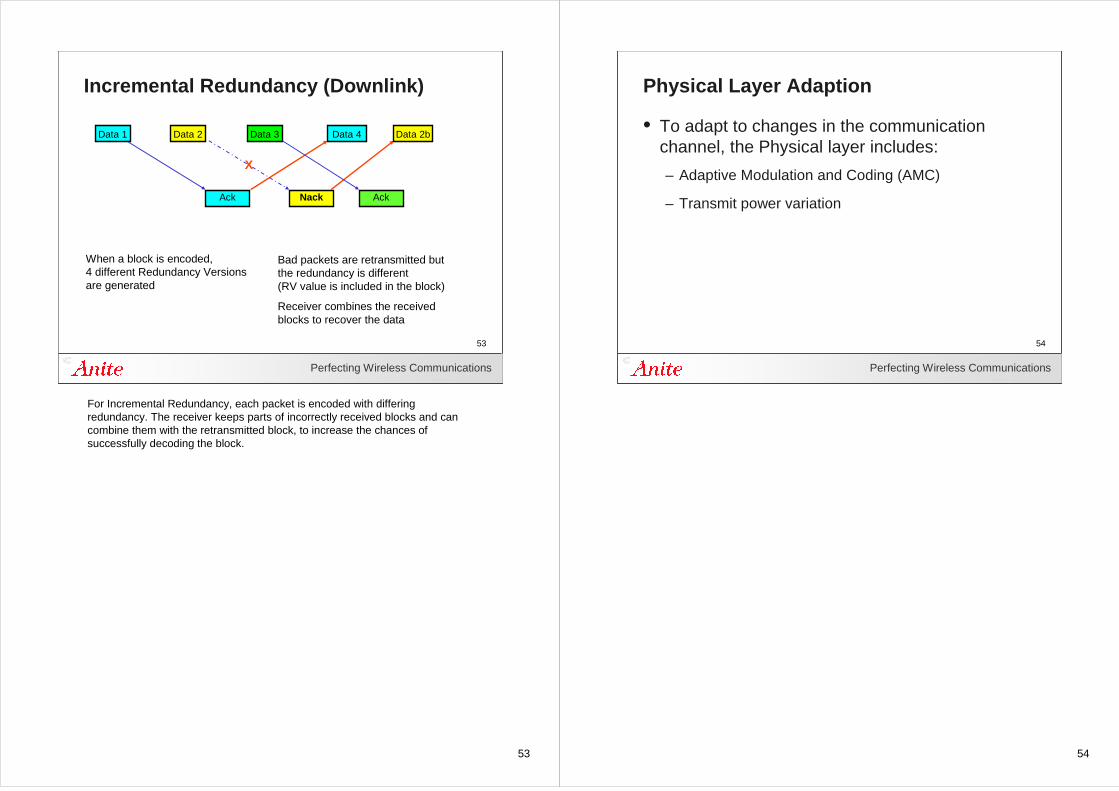
Bad packets are retransmitted but the redundancy is different(RV value is included in the block)
Receiver combines the received blocks to recover the data
When a block is encoded, 4 different Redundancy Versions are generated
Data 1 Data 2 Data 3 Data 4
Ack Nack Ack
X
Data 2b
For Incremental Redundancy, each packet is encoded with differing redundancy. The receiver keeps parts of incorrectly received blocks and can combine them with the retransmitted block, to increase the chances of successfully decoding the block.
54
Perfecting Wireless Communications
54
Physical Layer Adaption
• To adapt to changes in the communication channel, the Physical layer includes:
– Adaptive Modulation and Coding (AMC)
– Transmit power variation
55
Perfecting Wireless Communications
55
Modulation and Coding (AMC)
• Network selects coding scheme to match instantaneous channel conditions– Optimisation of capacity with a reasonable BLER– Reduction of latency but possibly lower throughput rate
• Modulation– QPSK, 16 QAM, 64 QAM
• Coding– Traffic and Paging 1/3 rate (0.33) Turbo coding– Rate matching adjusts the overall rate (0.08 to 0.93)– Broadcast channel 1/3 rate tail biting convolutional
Higher data rates -
More prone to interference
Used in small area around base station
When selecting the modulation and coding scheme, the network can focus either on optimisation of capacity or a reduction of latency (clearly with a balance between both parameters).
The set of supported coding schemes may not be fixed. They differ in their complexity to implement and in their efficiency for different types of data and possibly the latency introduced (block coding is good for data services but coding is performed over a great depth of data so introduces an inherent delay).
Additional coding methods are used for control information on PCFICH, PHICH, PDCCH and PUCCH
56
Perfecting Wireless Communications
56
Channel Quality Indicator
0.93
0.75
0.45
0.6
0.37
0.59
0.3
0.076
Coding Rate
5.664 QAM15
4.564 QAM13
2.764 QAM10
2.416 QAM9
1.516 QAM7
0.9QPSK6
0.6QPSK4
0.15QPSK1
Bits / symbolModulationCQI
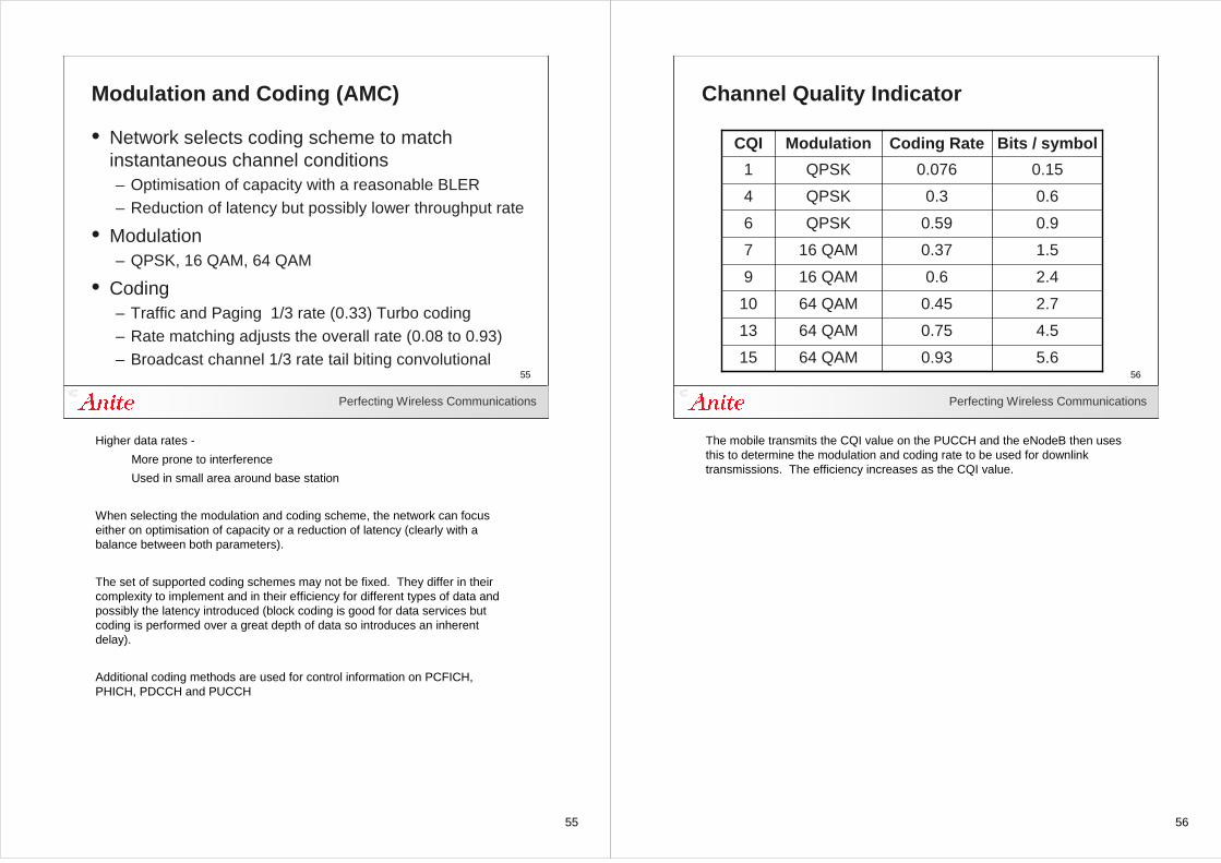
The mobile transmits the CQI value on the PUCCH and the eNodeB then uses this to determine the modulation and coding rate to be used for downlink transmissions. The efficiency increases as the CQI value.
57
Perfecting Wireless Communications
57
(1,-1)
(-1,1)
(-1,-1)
(1,1)
Q
I
Modulation Schemes
QPSK - 2 bits per symbol
Q
I
16-QAM - 4 bits per symbol
0001 0011
0000 0010
The first two modulation schemes are QPSK and 16 QAM. If the channel conditions are good, 16-QAM is used to increase the data rate since 4 bits are sent in parallel. This modulation scheme is less tolerant of poor channels and changes in received power since it includes a a power as well as a phase aspect to the modulation.
58
Perfecting Wireless Communications
58
Modulation Schemes - 64 QAM
Q
I
64-QAM - 6 bits per symbol
000011
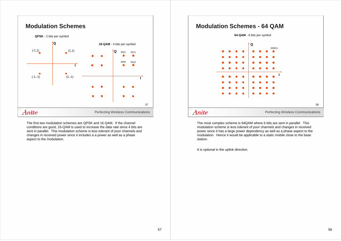
The most complex scheme is 64QAM where 6 bits are sent in parallel. This modulation scheme is less tolerant of poor channels and changes in received power since it has a large power dependency as well as a phase aspect to the modulation. Hence it would be applicable to a static mobile close to the base station.
It is optional in the uplink direction.
59
Perfecting Wireless Communications
59
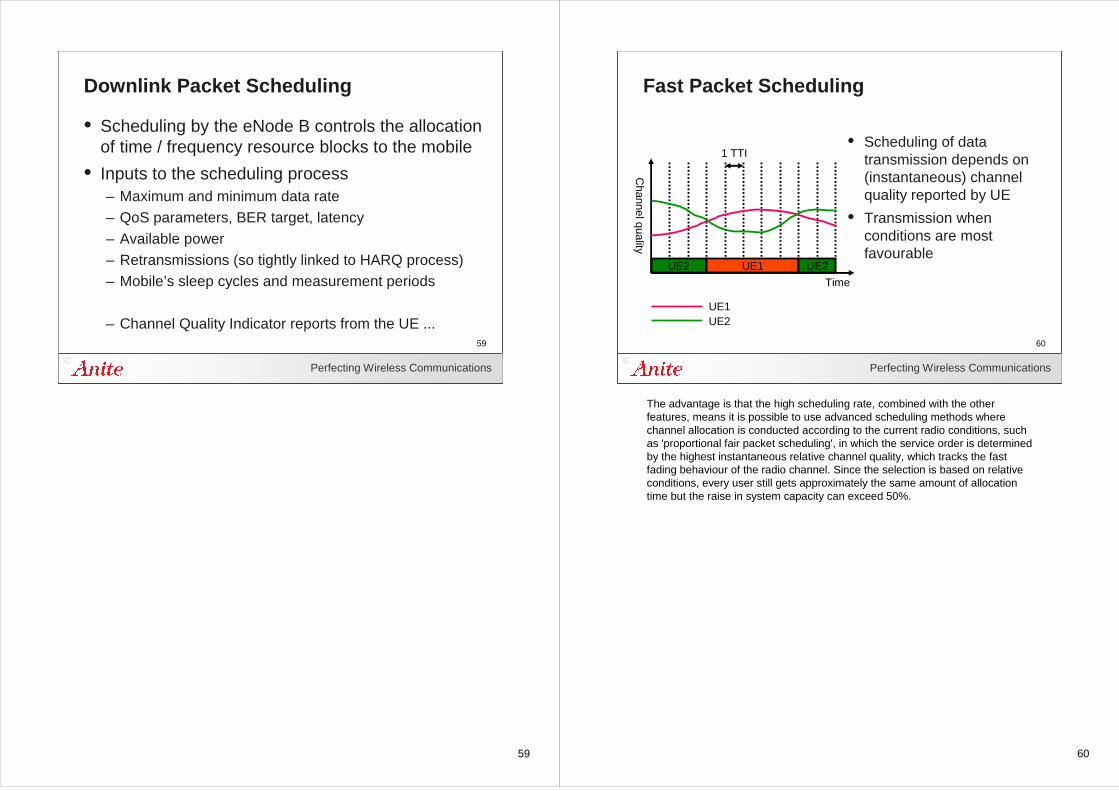
Downlink Packet Scheduling
• Scheduling by the eNode B controls the allocation of time / frequency resource blocks to the mobile
• Inputs to the scheduling process– Maximum and minimum data rate– QoS parameters, BER target, latency– Available power– Retransmissions (so tightly linked to HARQ process)– Mobile’s sleep cycles and measurement periods
– Channel Quality Indicator reports from the UE ...
60
Perfecting Wireless Communications
60
Fast Packet Scheduling
• Scheduling of data transmission depends on (instantaneous) channel quality reported by UE
• Transmission when conditions are most favourable
UE2 UE1 UE2
UE1UE2
1 TTI
Time
Channel quality
The advantage is that the high scheduling rate, combined with the other features, means it is possible to use advanced scheduling methods where channel allocation is conducted according to the current radio conditions, such as 'proportional fair packet scheduling', in which the service order is determined by the highest instantaneous relative channel quality, which tracks the fast fading behaviour of the radio channel. Since the selection is based on relative conditions, every user still gets approximately the same amount of allocation time but the raise in system capacity can exceed 50%.
61
Perfecting Wireless Communications
61
Downlink MIMO
• Multiple Input, Multiple Output
• Multiple antennas at the base station and mobile
• Improved reliability over poor channel conditions
• Increased data throughput
Transmitter
T
T R
R
Receiver
eNodeB Mobile
In the future, higher orders such as 4 x 2 MIMO are specified.
Antenna spacing has to be a minimum of about 1/4 wavelength (30mm) which is feasible on the mobile.
The terms are expressed from the viewpoint of the channel over which the radio signals are sent, hence
SIMO - single input multiple output (ie 1 antenna transmitting into the ether and 2 antennas receiving the output from the ether)
62
Perfecting Wireless Communications
62
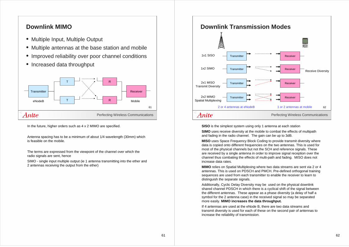
Downlink Transmission Modes
Transmitter Receiver1x1 SISO
Transmitter Receiver2x1 MISOTransmit Diversity
Transmitter Receiver2x2 MIMOSpatial Multiplexing
2 or 4 antennas at eNodeB 1 or 2 antennas at mobile
Transmitter Receiver1x2 SIMOReceive Diversity
SISO is the simplest system using only 1 antenna at each station
SIMO uses receive diversity at the mobile to combat the effects of multipath and fading in the radio channel. The gain can be up to 3dB.
MISO uses Space Frequency Block Coding to provide transmit diversity where data is copied onto different frequencies on the two antennas. This is used for most of the physical channels but not the SCH and reference signals. These are received by a single antenna in order to improve signal reception over the channel thus combating the effects of multi-path and fading. MISO does not increase data rates.
MIMO relies on Spatial Multiplexing where two data streams are sent via 2 or 4 antennas. This is used on PDSCH and PMCH. Pre-defined orthogonal training sequences are used from each transmitter to enable the receiver to learn to distinguish the separate signals.
Additionally, Cyclic Delay Diversity may be used on the physical downlink shared channel PDSCH in which there is a cyclical shift of the signal between the different antennas. These appear as a phase diversity (a delay of half a symbol for the 2 antenna case) in the received signal so may be separated more easily. MIMO increases the data throughput.
If 4 antennas are used at the eNode B, there are two data streams and transmit diversity is used for each of these on the second pair of antennas to increase the reliability of transmission.
63
Perfecting Wireless Communications
63
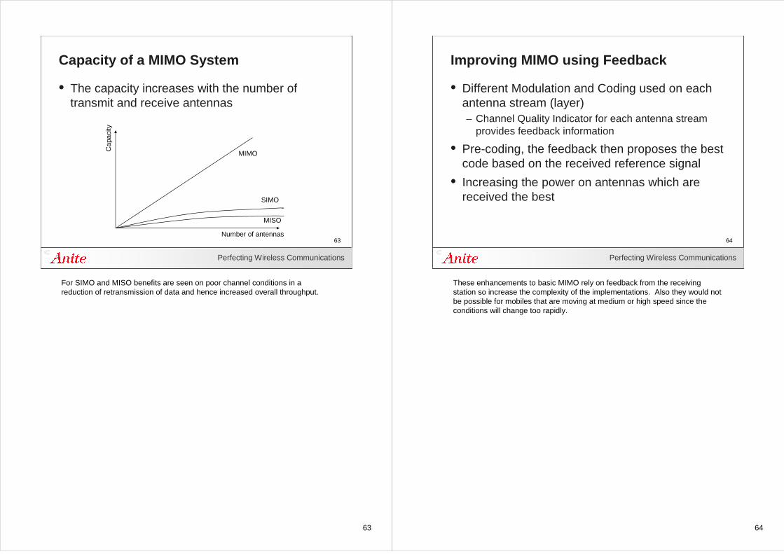
Capacity of a MIMO System
• The capacity increases with the number of transmit and receive antennas
Number of antennas
Cap
acity
MIMO
SIMO
MISO
For SIMO and MISO benefits are seen on poor channel conditions in a reduction of retransmission of data and hence increased overall throughput.
64
Perfecting Wireless Communications
64
Improving MIMO using Feedback
• Different Modulation and Coding used on each antenna stream (layer)– Channel Quality Indicator for each antenna stream
provides feedback information
• Pre-coding, the feedback then proposes the best code based on the received reference signal
• Increasing the power on antennas which are received the best
These enhancements to basic MIMO rely on feedback from the receiving station so increase the complexity of the implementations. Also they would not be possible for mobiles that are moving at medium or high speed since the conditions will change too rapidly.
65
65Perfecting Wireless Communications
65
Uplink Physical Layer
66
Perfecting Wireless Communications
66
Uplink Transmission
• Uplink uses Single Carrier FDMA
• Flexible bandwidth allocation 1.4 to 20 MHz
• 12 consecutive sub-carriers during one slot form one resource block
• 6 to 110 resource blocks
• 15 kHz sub-carrier spacing
In the uplink, the scheme used is called single carrier FDMA, in this the symbols are spread on a group of sub-carriers. This is alternatively called DFT-SOFDM, discrete Fourier transform - spread othogonal frequency division multiplex.
OFDMA is not used in the uplink since the Peak Average Power Ratio is high so with low cost power amplifiers in the mobile this would give rise to high spectral spreading (interference between adjacent channels ) and hence poor BER.
67
Perfecting Wireless Communications
67
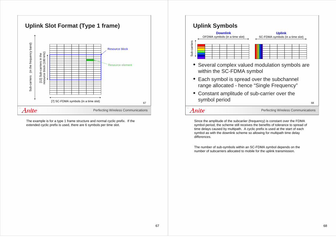
Uplink Slot Format (Type 1 frame)S
ub-c
arrie
rs
(in th
e fr
eque
ncy
band
)
Resource block
Resource element
[7] SC-FDMA symbols (in a time slot)
[12]
Sub
-car
riers
in th
e re
sour
ce b
lock
(18
0 kH
z)
The example is for a type 1 frame structure and normal cyclic prefix. If the extended cyclic prefix is used, there are 6 symbols per time slot.
68
Perfecting Wireless Communications
68
Uplink SymbolsUplink
SC-FDMA symbols (in a time slot)
• Several complex valued modulation symbols are within the SC-FDMA symbol
• Each symbol is spread over the subchannel range allocated - hence “Single Frequency”
• Constant amplitude of sub-carrier over the symbol period
DownlinkOFDMA symbols (in a time slot)
Sub
-car
riers
Since the amplitude of the subcariier (frequency) is constant over the FDMA symbol period, the scheme still receives the benefits of tolerance to spread of time delays caused by multipath. A cyclic prefix is used at the start of each symbol as with the downlink scheme so allowing for multipath time delay differences.
The number of sub-symbols within an SC-FDMA symbol depends on the number of subcarriers allocated to mobile for the uplink transmission.
69
Perfecting Wireless Communications
69
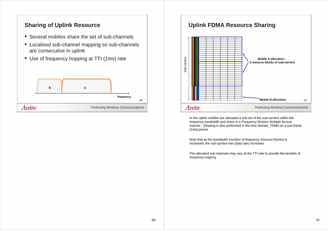
Sharing of Uplink Resource
• Several mobiles share the set of sub-channels
• Localised sub-channel mapping so sub-channels are consecutive in uplink
• Use of frequency hopping at TTI (1ms) rate
B A
frequency
70
Perfecting Wireless Communications
70
Uplink FDMA Resource Sharing
Mobile A allocation -2 resource blocks of sub-carriers
Mobile B allocation
Sub
-car
riers
In the uplink mobiles are allocated a sub-set of the sub-carriers within the frequency bandwidth and share in a Frequency Division Multiple Access manner. (Sharing is also performed in the time domain, TDMA on a sub-frame (1ms) period.
Note that as the bandwidth (number of frequency resource blocks) is increased, the sub-symbol rate (data rate) increases.
The allocated sub-channels may vary at the TTI rate to provide the benefits of frequency hopping
71
Perfecting Wireless Communications
71
Physical Layer Adaption
• Adaption is similar to the Downlink physical layer
– Adaptive Modulation and Coding (AMC)
– Control of uplink transmit power
72
72Perfecting Wireless Communications
72
Power Control
73
Perfecting Wireless Communications
73
Power Control Requirements
• Power control is important to minimise interference from other mobiles or cells
• Ensures that signals from all mobiles are received at similar level by the eNodeB
• Reduces interference received by the mobile from neighbour cells
Accurate power control is important (but not as essential as in CDMA) to ensure near-neighbouring cells can reuse frequencies.
In the uplink, transmissions from the mobiles are adjusted so that all of the signals from the mobiles are received at the same power level. If this were not performed, a mobile close to the base station would “drown out” signals from mobiles that were further away.
74
Perfecting Wireless Communications
74
Transmit Power Control (Uplink)
• Open Loop Control– Used on PRACH – Transmit power level derived from received power
and a base level in downlink signalling
• Closed Loop Control– Dynamically controlled by Transmitter Power Control
commands on PDCCH• Accumulative (relative power offsets, -1, 0, +1, +3 dB)• Absolute power level
– Adjustment from the Modulation and Coding Scheme– Optimised per Resource Block (frequency dependant)
In closed loop operation, the modulation and coding scheme may change the modulation type. Each modulation type has a related default value for the power offset.
75
Perfecting Wireless Communications
75
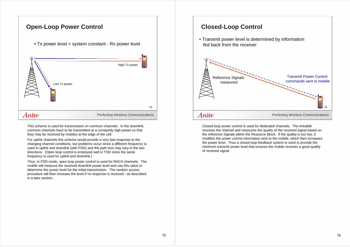
Open-Loop Power Control
• Tx power level = system constant - Rx power level
High Tx power
Low Tx power
This scheme is used for transmission on common channels. In the downlink, common channels have to be transmitted at a constantly high power so that they may be received by mobiles at the edge of the cell.
For uplink channels this scheme would provide a very fast response to the changing channel conditions, but problems occur since a different frequency is used in uplink and downlink (with FDD) and the path loss may vary in the two directions. (Open loop control is employed well in TDD since the same frequency is used for uplink and downlink.)
Thus, in FDD mode, open loop power control is used for RACH channels. The mobile will measure the received downlink power level and use this value to determine the power level for the initial transmission. The random access procedure will then increase the level if no response is received - as described in a later section.
76
Perfecting Wireless Communications
76
Closed-Loop Control
Reference Signals measured
Transmit Power Control commands sent to mobile
• Transmit power level is determined by information fed back from the receiver
Closed-loop power control is used for dedicated channels. The eNodeB receives the channel and measures the quality of the received signal based on the reference Signals within the Resource Block. If the quality is too low, it modifies the power control information sent to the mobile, which then increases the power level. Thus a closed loop feedback system is used to provide the minimum transmit power level that ensures the mobile receives a good quality of received signal.
77
Perfecting Wireless Communications
77
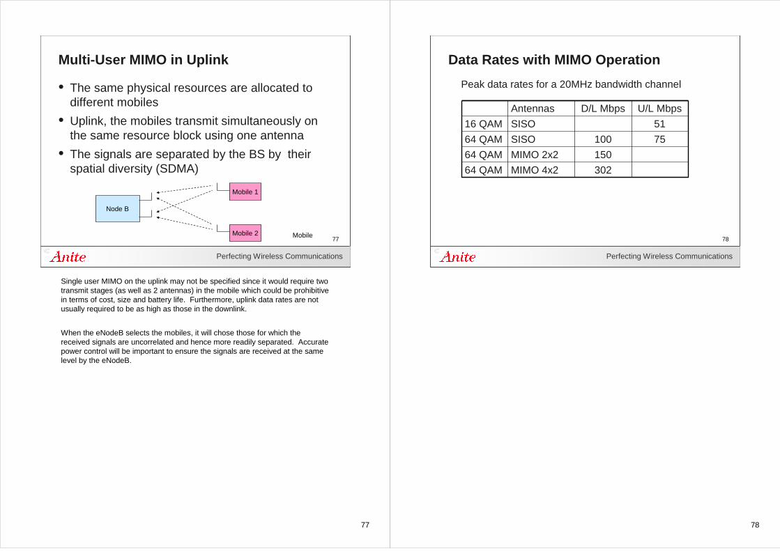
Multi-User MIMO in Uplink
• The same physical resources are allocated to different mobiles
• Uplink, the mobiles transmit simultaneously on the same resource block using one antenna
• The signals are separated by the BS by their spatial diversity (SDMA)
Node B
Mobile 2
Mobile 1
Mobile
Single user MIMO on the uplink may not be specified since it would require two transmit stages (as well as 2 antennas) in the mobile which could be prohibitive in terms of cost, size and battery life. Furthermore, uplink data rates are not usually required to be as high as those in the downlink.
When the eNodeB selects the mobiles, it will chose those for which the received signals are uncorrelated and hence more readily separated. Accurate power control will be important to ensure the signals are received at the same level by the eNodeB.
78
Perfecting Wireless Communications
78
Data Rates with MIMO Operation
302MIMO 4x264 QAM
150MIMO 2x264 QAM
75100SISO64 QAM
51SISO16 QAM
U/L MbpsD/L MbpsAntennas
Peak data rates for a 20MHz bandwidth channel
79
79Perfecting Wireless Communications
79
Downlink Physical Channels
80
Perfecting Wireless Communications
80
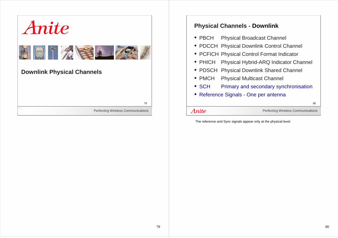
Physical Channels - Downlink
• PBCH Physical Broadcast Channel
• PDCCH Physical Downlink Control Channel
• PCFICH Physical Control Format Indicator
• PHICH Physical Hybrid-ARQ Indicator Channel
• PDSCH Physical Downlink Shared Channel
• PMCH Physical Multicast Channel
• SCH Primary and secondary synchronisation
• Reference Signals - One per antenna
The reference and Sync signals appear only at the physical level.
81
Perfecting Wireless Communications
81
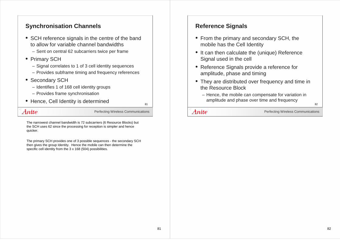
Synchronisation Channels
• SCH reference signals in the centre of the band to allow for variable channel bandwidths– Sent on central 62 subcarriers twice per frame
• Primary SCH– Signal correlates to 1 of 3 cell identity sequences– Provides subframe timing and frequency references
• Secondary SCH– Identifies 1 of 168 cell identity groups– Provides frame synchronisation
• Hence, Cell Identity is determined
The narrowest channel bandwidth is 72 subcarriers (6 Resource Blocks) but the SCH uses 62 since the processing for reception is simpler and hence quicker.
The primary SCH provides one of 3 possible sequences - the secondary SCH then gives the group Identity. Hence the mobile can then determine the specific cell identity from the 3 x 168 (504) possibilities.
82
Perfecting Wireless Communications
82
Reference Signals
• From the primary and secondary SCH, the mobile has the Cell Identity
• It can then calculate the (unique) Reference Signal used in the cell
• Reference Signals provide a reference for amplitude, phase and timing
• They are distributed over frequency and time in the Resource Block– Hence, the mobile can compensate for variation in
amplitude and phase over time and frequency
83
Perfecting Wireless Communications
83
Downlink Reference SignalsS
ub-c
arrie
rs
(in th
e fr
eque
ncy
band
)
OFDM symbols (in a time slot)
Second reference symbol
First reference symbol
Data
Resource block
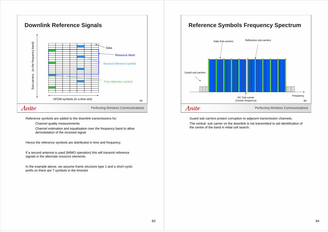
Reference symbols are added to the downlink transmissions for:
Channel quality measurements
Channel estimation and equalisation over the frequency band to allow demodulation of the received signal
Hence the reference symbols are distributed in time and frequency.
If a second antenna is used (MIMO operation) this will transmit reference signals in the alternate resource elements.
In the example above, we assume frame structure type 1 and a short cyclic prefix so there are 7 symbols in the timeslot
84
Perfecting Wireless Communications
84
Reference Symbols Frequency Spectrum
DC Sub-carrier(Centre frequency)
Data Sub-carriers Reference sub-carriers
Guard sub-carriers
Frequency
Guard sub carriers protect corruption to adjacent transmission channels.
The central sub carrier on the downlink is not transmitted to aid identification of the centre of the band in initial cell search.
85
Perfecting Wireless Communications
85
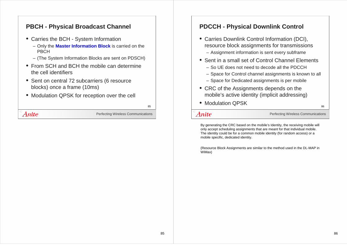
PBCH - Physical Broadcast Channel
• Carries the BCH - System Information – Only the Master Information Block is carried on the
PBCH– (The System Information Blocks are sent on PDSCH)
• From SCH and BCH the mobile can determine the cell identifiers
• Sent on central 72 subcarriers (6 resource blocks) once a frame (10ms)
• Modulation QPSK for reception over the cell
86
Perfecting Wireless Communications
86
PDCCH - Physical Downlink Control
• Carries Downlink Control Information (DCI), resource block assignments for transmissions– Assignment information is sent every subframe
• Sent in a small set of Control Channel Elements– So UE does not need to decode all the PDCCH– Space for Control channel assignments is known to all– Space for Dedicated assignments is per mobile
• CRC of the Assignments depends on the mobile’s active identity (implicit addressing)
• Modulation QPSK
By generating the CRC based on the mobile’s Identity, the receiving mobile will only accept scheduling assignments that are meant for that individual mobile. The identity could be for a common mobile identity (for random access) or a mobile specific, dedicated identity.
(Resource Block Assignments are similar to the method used in the DL-MAP in WiMax)
87
Perfecting Wireless Communications
87
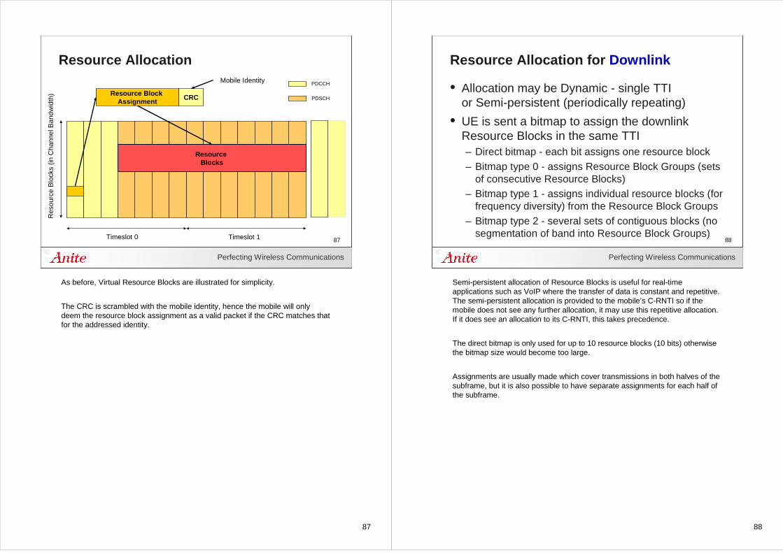
Resource AllocationR
esou
rce
Blo
cks
(in C
hann
el B
andw
idth
)
Timeslot 0 Timeslot 1
PDCCH
PDSCH
Resource Blocks
Resource Block Assignment
CRC
Mobile Identity
As before, Virtual Resource Blocks are illustrated for simplicity.
The CRC is scrambled with the mobile identity, hence the mobile will only deem the resource block assignment as a valid packet if the CRC matches that for the addressed identity.
88
Perfecting Wireless Communications
88
Resource Allocation for Downlink
• Allocation may be Dynamic - single TTIor Semi-persistent (periodically repeating)
• UE is sent a bitmap to assign the downlink Resource Blocks in the same TTI– Direct bitmap - each bit assigns one resource block– Bitmap type 0 - assigns Resource Block Groups (sets
of consecutive Resource Blocks)– Bitmap type 1 - assigns individual resource blocks (for
frequency diversity) from the Resource Block Groups– Bitmap type 2 - several sets of contiguous blocks (no
segmentation of band into Resource Block Groups)
Semi-persistent allocation of Resource Blocks is useful for real-time applications such as VoIP where the transfer of data is constant and repetitive. The semi-persistent allocation is provided to the mobile’s C-RNTI so if the mobile does not see any further allocation, it may use this repetitive allocation. If it does see an allocation to its C-RNTI, this takes precedence.
The direct bitmap is only used for up to 10 resource blocks (10 bits) otherwise the bitmap size would become too large.
Assignments are usually made which cover transmissions in both halves of the subframe, but it is also possible to have separate assignments for each half of the subframe.
89
Perfecting Wireless Communications
89
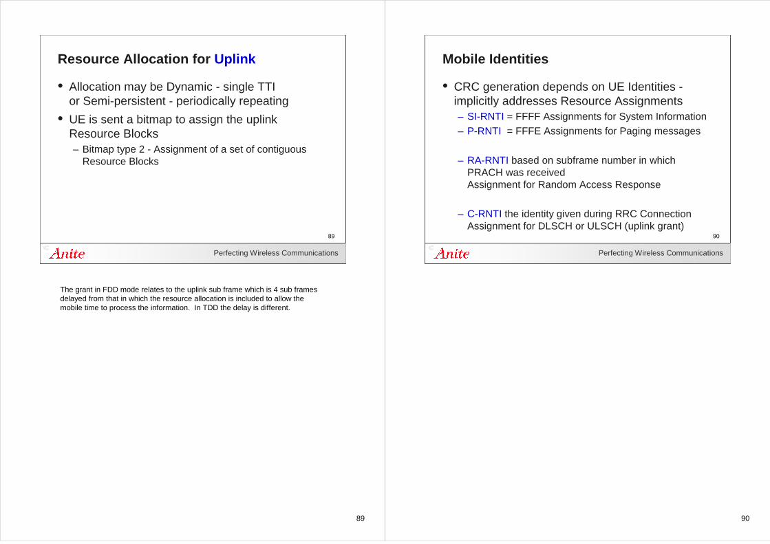
Resource Allocation for Uplink
• Allocation may be Dynamic - single TTIor Semi-persistent - periodically repeating
• UE is sent a bitmap to assign the uplink Resource Blocks– Bitmap type 2 - Assignment of a set of contiguous
Resource Blocks
The grant in FDD mode relates to the uplink sub frame which is 4 sub frames delayed from that in which the resource allocation is included to allow the mobile time to process the information. In TDD the delay is different.
90
Perfecting Wireless Communications
90
Mobile Identities
• CRC generation depends on UE Identities -implicitly addresses Resource Assignments– SI-RNTI = FFFF Assignments for System Information– P-RNTI = FFFE Assignments for Paging messages
– RA-RNTI based on subframe number in which PRACH was receivedAssignment for Random Access Response
– C-RNTI the identity given during RRC ConnectionAssignment for DLSCH or ULSCH (uplink grant)
91
Perfecting Wireless Communications
91
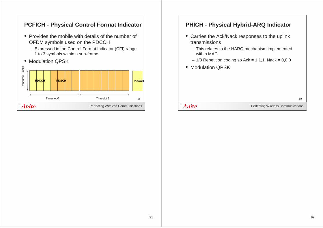
PCFICH - Physical Control Format Indicator
• Provides the mobile with details of the number of OFDM symbols used on the PDCCH– Expressed in the Control Format Indicator (CFI) range
1 to 3 symbols within a sub-frame
• Modulation QPSK
Res
ourc
e B
lock
s
Timeslot 0 Timeslot 1
PDCCH PDSCH PDCCH
92
Perfecting Wireless Communications
92
PHICH - Physical Hybrid-ARQ Indicator
• Carries the Ack/Nack responses to the uplink transmissions– This relates to the HARQ mechanism implemented
within MAC– 1/3 Repetition coding so Ack = 1,1,1, Nack = 0,0,0
• Modulation QPSK
93
Perfecting Wireless Communications
93
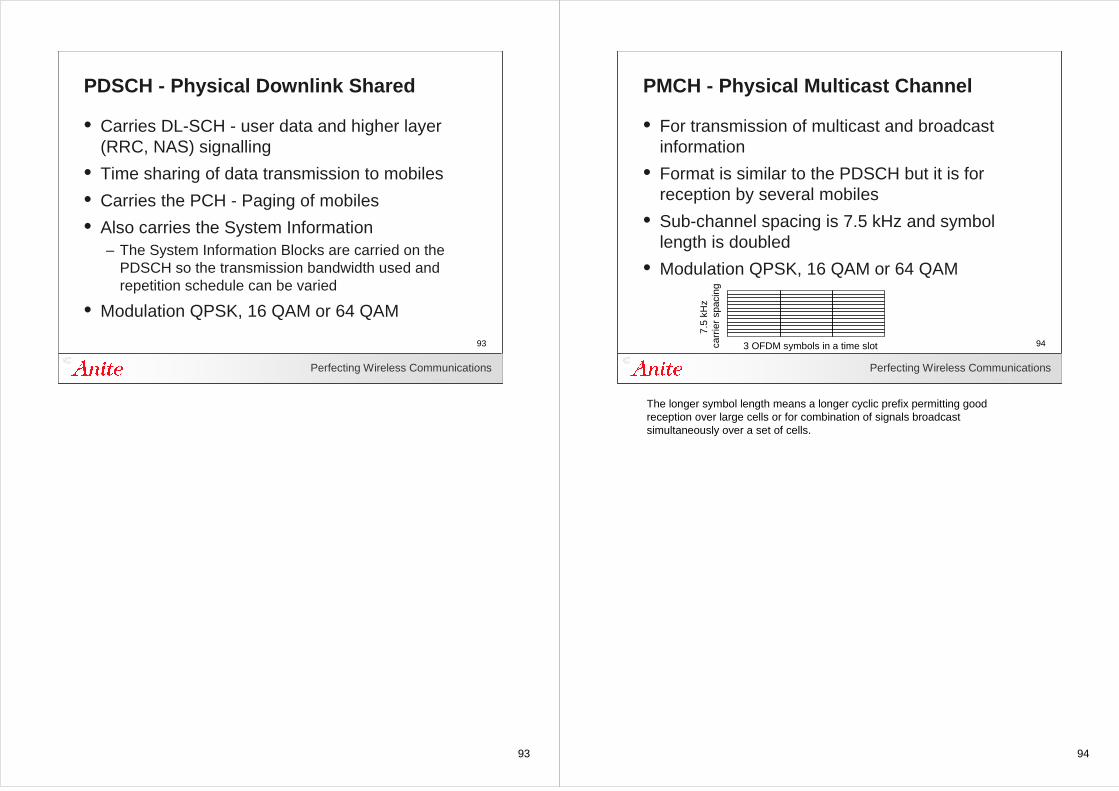
PDSCH - Physical Downlink Shared
• Carries DL-SCH - user data and higher layer (RRC, NAS) signalling
• Time sharing of data transmission to mobiles
• Carries the PCH - Paging of mobiles
• Also carries the System Information– The System Information Blocks are carried on the
PDSCH so the transmission bandwidth used and repetition schedule can be varied
• Modulation QPSK, 16 QAM or 64 QAM
94
Perfecting Wireless Communications
94
PMCH - Physical Multicast Channel
• For transmission of multicast and broadcast information
• Format is similar to the PDSCH but it is for reception by several mobiles
• Sub-channel spacing is 7.5 kHz and symbol length is doubled
• Modulation QPSK, 16 QAM or 64 QAM
3 OFDM symbols in a time slot
7.5
kHz
carr
ier
spac
ing
The longer symbol length means a longer cyclic prefix permitting good reception over large cells or for combination of signals broadcast simultaneously over a set of cells.
95
Perfecting Wireless Communications
95
Example Channel MappingR
esou
rce
Blo
cks
(in C
hann
el B
andw
idth
)
Timeslot 0
ReferenceSignals
Timeslot 1
P-SCH
S-SCH
PBCH PDCCH PDSCH
Timeslot 0 and 5 Timeslot 1Every Timeslot Even Timeslots
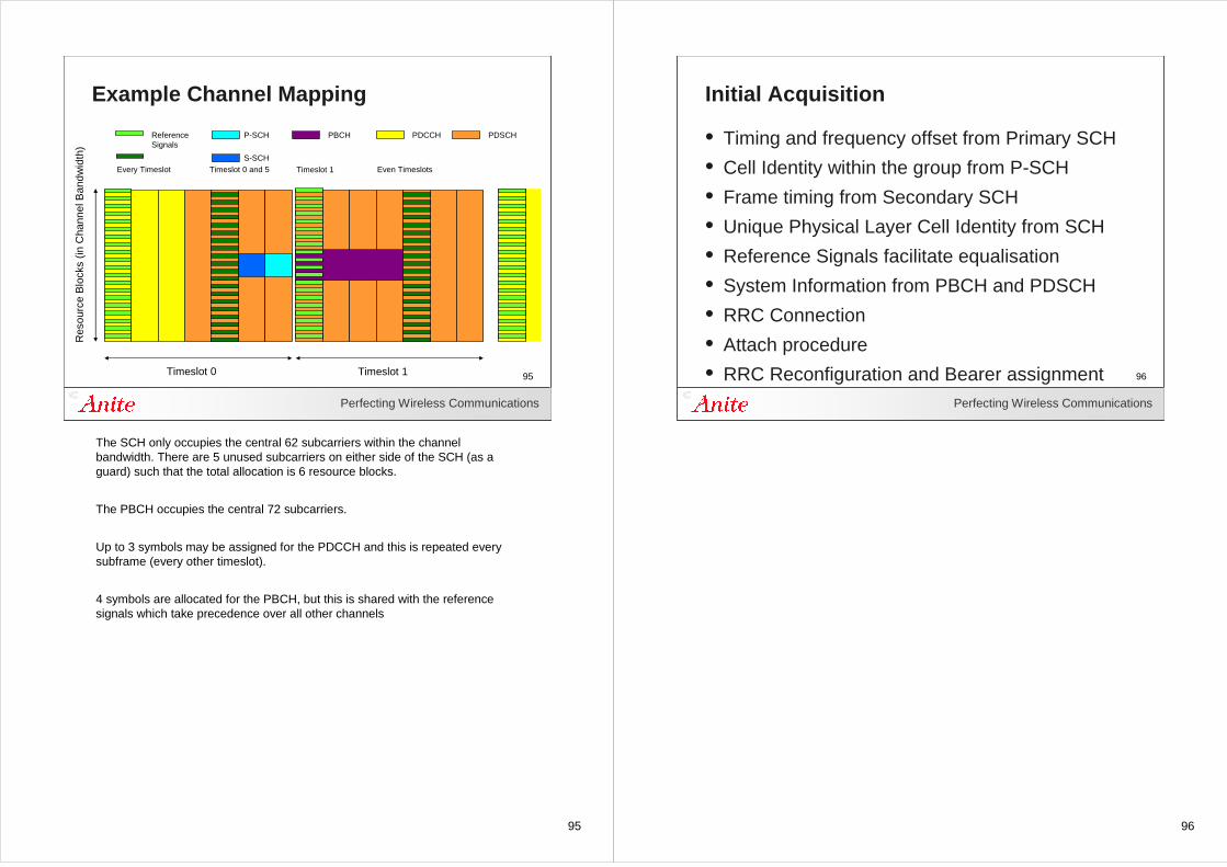
The SCH only occupies the central 62 subcarriers within the channel bandwidth. There are 5 unused subcarriers on either side of the SCH (as a guard) such that the total allocation is 6 resource blocks.
The PBCH occupies the central 72 subcarriers.
Up to 3 symbols may be assigned for the PDCCH and this is repeated every subframe (every other timeslot).
4 symbols are allocated for the PBCH, but this is shared with the reference signals which take precedence over all other channels
96
Perfecting Wireless Communications
96
Initial Acquisition
• Timing and frequency offset from Primary SCH
• Cell Identity within the group from P-SCH
• Frame timing from Secondary SCH
• Unique Physical Layer Cell Identity from SCH
• Reference Signals facilitate equalisation
• System Information from PBCH and PDSCH
• RRC Connection
• Attach procedure
• RRC Reconfiguration and Bearer assignment
97
97Perfecting Wireless Communications
97
Uplink Physical Channels
98
Perfecting Wireless Communications
98
Physical Channels - Uplink
• PUCCH Physical Uplink Control Channel
• PUSCH Physical Uplink Shared Channel
• PRACH Physical Random Access Channel
• DMRS Demodulation Reference Signal
• SRS Sounding Reference Signal
99
Perfecting Wireless Communications
99
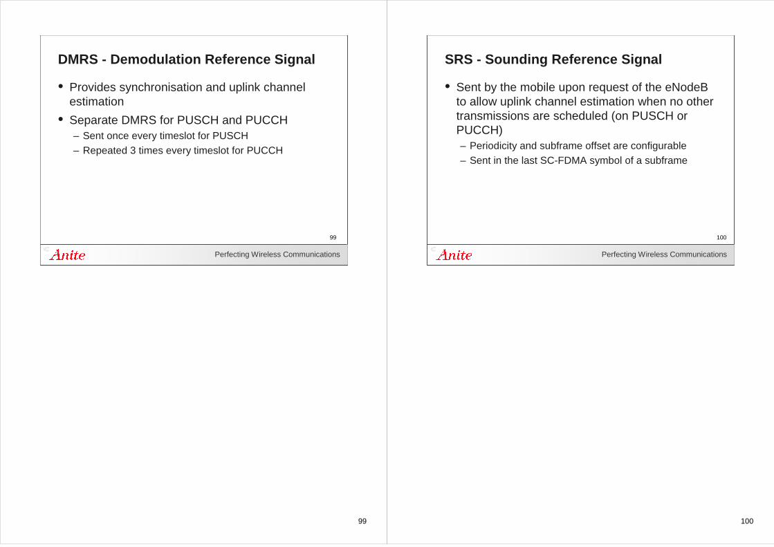
DMRS - Demodulation Reference Signal
• Provides synchronisation and uplink channel estimation
• Separate DMRS for PUSCH and PUCCH– Sent once every timeslot for PUSCH– Repeated 3 times every timeslot for PUCCH
100
Perfecting Wireless Communications
100
SRS - Sounding Reference Signal
• Sent by the mobile upon request of the eNodeB to allow uplink channel estimation when no other transmissions are scheduled (on PUSCH or PUCCH)– Periodicity and subframe offset are configurable– Sent in the last SC-FDMA symbol of a subframe
101
Perfecting Wireless Communications
101
PUCCH - Physical Uplink Control Channel
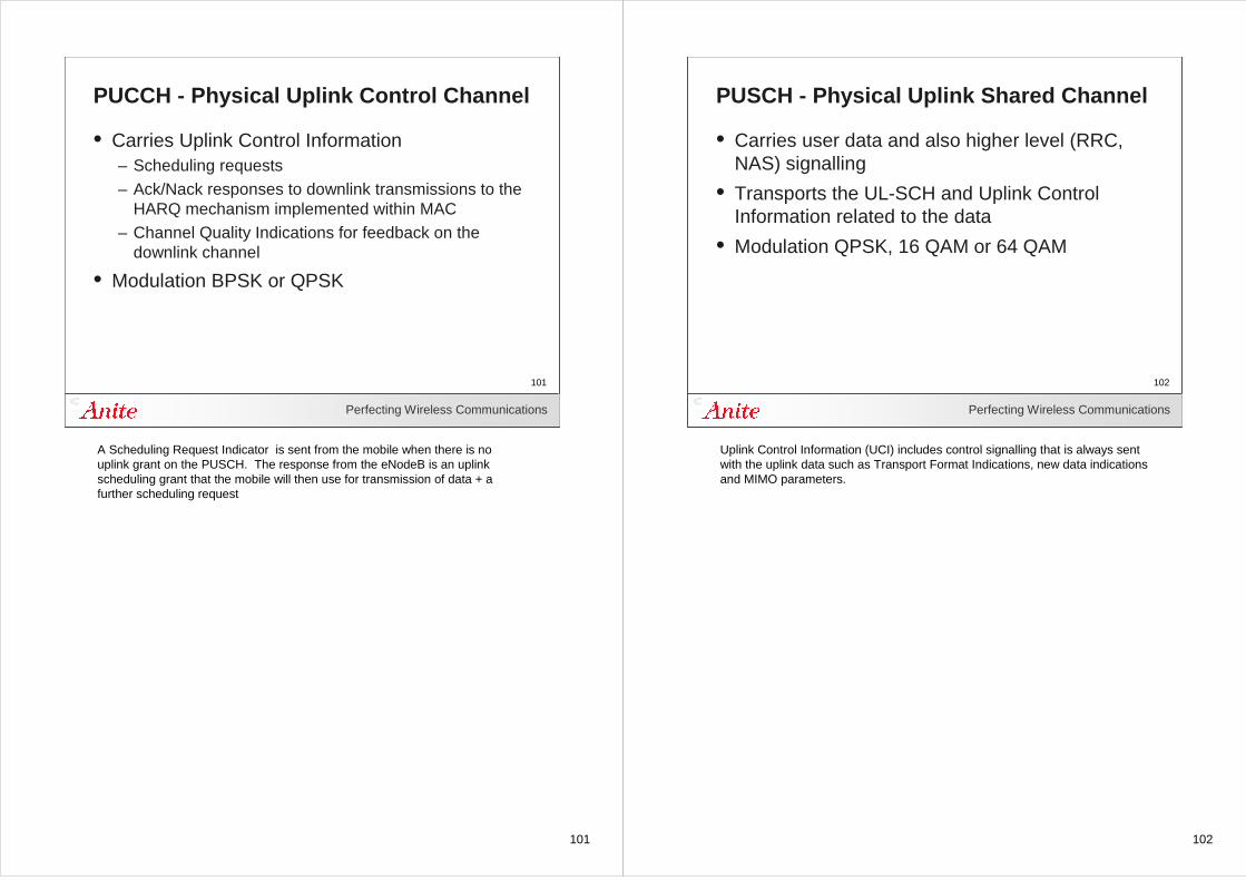
• Carries Uplink Control Information– Scheduling requests– Ack/Nack responses to downlink transmissions to the
HARQ mechanism implemented within MAC– Channel Quality Indications for feedback on the
downlink channel
• Modulation BPSK or QPSK
A Scheduling Request Indicator is sent from the mobile when there is no uplink grant on the PUSCH. The response from the eNodeB is an uplink scheduling grant that the mobile will then use for transmission of data + a further scheduling request
102
Perfecting Wireless Communications
102
PUSCH - Physical Uplink Shared Channel
• Carries user data and also higher level (RRC, NAS) signalling
• Transports the UL-SCH and Uplink Control Information related to the data
• Modulation QPSK, 16 QAM or 64 QAM
Uplink Control Information (UCI) includes control signalling that is always sent with the uplink data such as Transport Format Indications, new data indications and MIMO parameters.
103
Perfecting Wireless Communications
103
Example Channel MappingR
esou
rce
Blo
cks
(in C
hann
el B
andw
idth
)
Timeslot 0
DemodulationReferenceSignal
Timeslot 1
PUSCH
Every Timeslot
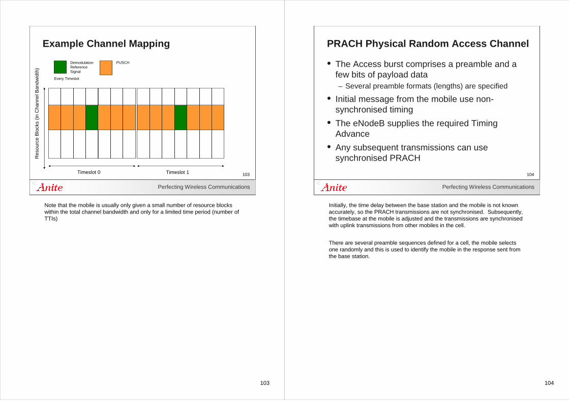
Note that the mobile is usually only given a small number of resource blocks within the total channel bandwidth and only for a limited time period (number of TTIs)
104
Perfecting Wireless Communications
104
PRACH Physical Random Access Channel
• The Access burst comprises a preamble and a few bits of payload data– Several preamble formats (lengths) are specified
• Initial message from the mobile use non-synchronised timing
• The eNodeB supplies the required Timing Advance
• Any subsequent transmissions can use synchronised PRACH
Initially, the time delay between the base station and the mobile is not known accurately, so the PRACH transmissions are not synchronised. Subsequently, the timebase at the mobile is adjusted and the transmissions are synchronised with uplink transmissions from other mobiles in the cell.
There are several preamble sequences defined for a cell, the mobile selects one randomly and this is used to identify the mobile in the response sent from the base station.
105
Perfecting Wireless Communications
105
Random Access
Network UE
Random Access Preamble
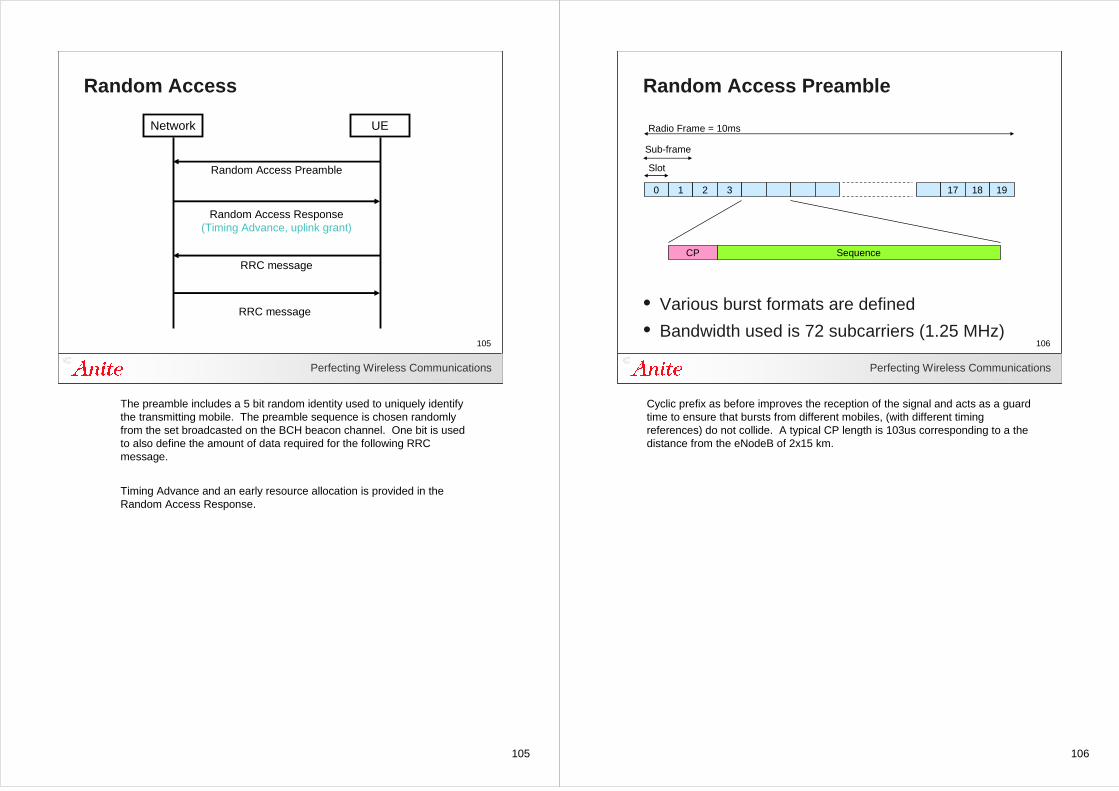
Random Access Response(Timing Advance, uplink grant)
RRC message
RRC message
The preamble includes a 5 bit random identity used to uniquely identify the transmitting mobile. The preamble sequence is chosen randomly from the set broadcasted on the BCH beacon channel. One bit is used to also define the amount of data required for the following RRCmessage.
Timing Advance and an early resource allocation is provided in the Random Access Response.
106
Perfecting Wireless Communications
106
Random Access Preamble
0 1 2 3 17 18 19
Slot
Sub-frame
Radio Frame = 10ms
CP Sequence
• Various burst formats are defined
• Bandwidth used is 72 subcarriers (1.25 MHz)
Cyclic prefix as before improves the reception of the signal and acts as a guard time to ensure that bursts from different mobiles, (with different timing references) do not collide. A typical CP length is 103us corresponding to a the distance from the eNodeB of 2x15 km.
107
Perfecting Wireless Communications
107
Power Control for Access Procedure
P
P
Power
…
N Retransmissions max
Message PUSCH
Timing, resource allocationand Sequence number
on PDCCH
Time
P
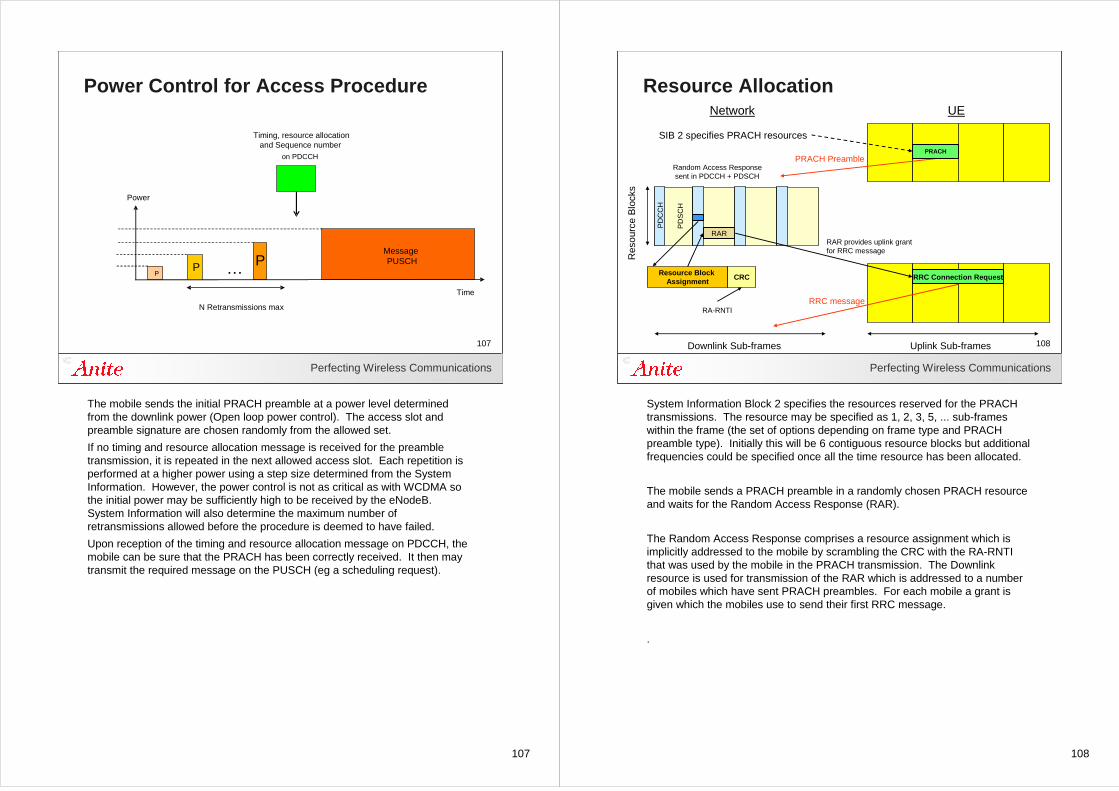
The mobile sends the initial PRACH preamble at a power level determined from the downlink power (Open loop power control). The access slot and preamble signature are chosen randomly from the allowed set.
If no timing and resource allocation message is received for the preamble transmission, it is repeated in the next allowed access slot. Each repetition is performed at a higher power using a step size determined from the System Information. However, the power control is not as critical as with WCDMA so the initial power may be sufficiently high to be received by the eNodeB. System Information will also determine the maximum number of retransmissions allowed before the procedure is deemed to have failed.
Upon reception of the timing and resource allocation message on PDCCH, the mobile can be sure that the PRACH has been correctly received. It then may transmit the required message on the PUSCH (eg a scheduling request).
108
Perfecting Wireless Communications
108
Resource Allocation
Res
ourc
e B
lock
s
Downlink Sub-frames Uplink Sub-frames
Random Access Responsesent in PDCCH + PDSCH
Resource Block Assignment
CRC
RA-RNTI
Network UE
SIB 2 specifies PRACH resources
PD
SC
H
PD
CC
H
RRC Connection Request
PRACHPRACH Preamble
RRC message
RARRAR provides uplink grant for RRC message
System Information Block 2 specifies the resources reserved for the PRACH transmissions. The resource may be specified as 1, 2, 3, 5, ... sub-frames within the frame (the set of options depending on frame type and PRACH preamble type). Initially this will be 6 contiguous resource blocks but additional frequencies could be specified once all the time resource has been allocated.
The mobile sends a PRACH preamble in a randomly chosen PRACH resource and waits for the Random Access Response (RAR).
The Random Access Response comprises a resource assignment which is implicitly addressed to the mobile by scrambling the CRC with the RA-RNTI that was used by the mobile in the PRACH transmission. The Downlink resource is used for transmission of the RAR which is addressed to a number of mobiles which have sent PRACH preambles. For each mobile a grant is given which the mobiles use to send their first RRC message.
.
109
Perfecting Wireless Communications
109
Timing Advance
eNodeB symbol
Uplink received symbol
Near
Far
Uplink received symbol
Required Timing Advance
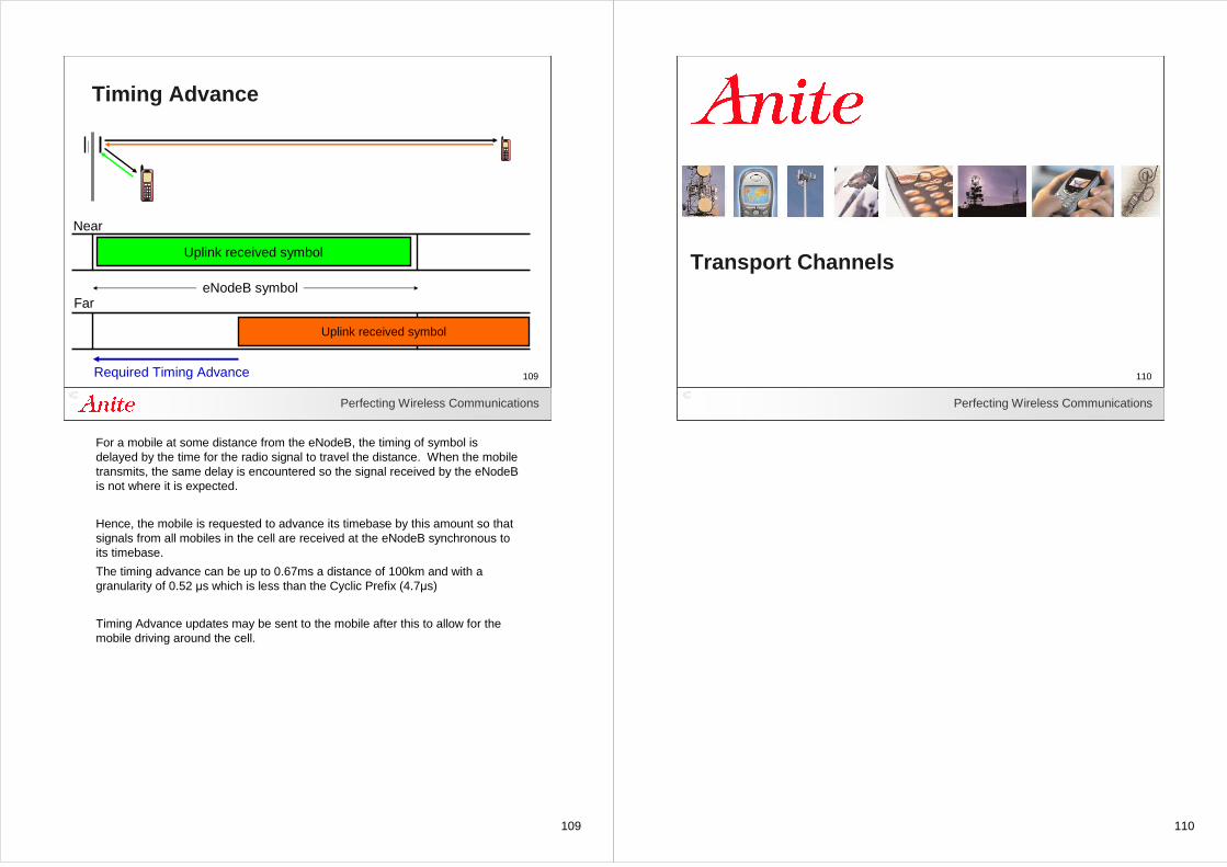
For a mobile at some distance from the eNodeB, the timing of symbol is delayed by the time for the radio signal to travel the distance. When the mobile transmits, the same delay is encountered so the signal received by the eNodeB is not where it is expected.
Hence, the mobile is requested to advance its timebase by this amount so that signals from all mobiles in the cell are received at the eNodeB synchronous to its timebase.
The timing advance can be up to 0.67ms a distance of 100km and with a granularity of 0.52 µs which is less than the Cyclic Prefix (4.7µs)
Timing Advance updates may be sent to the mobile after this to allow for the mobile driving around the cell.
110
110Perfecting Wireless Communications
110
Transport Channels
111
Perfecting Wireless Communications
111
Transport Channels - Downlink
• BCH Broadcast Channel– Carries the Master Information Block
• PCH Paging Channel
• DL-SCH Downlink Shared Channel– Carries user data and higher level signalling– Carries the System Information Blocks– May carry MBMS transmissions (when in a single cell)
• MCH Multicast Channel– support for MBSFN combining MBMS on multiple cells
Transport channels define how the data is transferred between the mobile and the eNodeB, for example error protection, channel coding and CRC, data packet size. This information is described by the Transport Format.
BCH uses a fixed transport format
PCH - usual Discontinuous reception so the mobile can sleep most of the time.
DL-SCH support for HARQ at MAC layer
dynamic link adaption used (modulation, coding and power controlschemes)
support for dynamic and semi-static (repeating) resource allocations.
may use DRX for mobile power saving.
MBSFN Multimedia Broadcast multicast service Single Frequency Network
112
Perfecting Wireless Communications
112
Transport Channels - Uplink
• UL-SCH Uplink Shared Channel– Carries user data and higher level signalling
• RACH Random Access Channel
UL-SCH
dynamic link adaption used (modulation, coding and power controlschemes)
support for dynamic and semi-static (repeating) resource allocations.
RACH
Carries little control information
contention risk since random access
113
Perfecting Wireless Communications
113
Logical Channels - Control
• BCCH Broadcast Control Channel– Distribution of System Information
• PCCH Paging Control Channel – Paging mobiles for MT sessions
• CCCH Common Control Channel– Bi-directional, used prior to RRC Connection
• DCCH Dedicated Control Channel– Bi-directional, RRC and NAS signalling information
• MCCH Multicast Control Channel– Transmission of MBMS signalling to mobiles
114
Perfecting Wireless Communications
114
Logical Channels - Traffic
• DTCH Dedicated Traffic Channel– Bi-directional transfer of user data (and application
level signalling)
• MTCH Multicast Traffic Channel– For transfer of MBMS data to mobiles
115
Perfecting Wireless Communications
115
Channel Mapping
Transport Channels
Physical Channels
Logical Channels PCCHBCCH CCCH DCCH DTCH MCCH MTCH
PCHBCH UL-SCH DL-SCH MCH RACH
PBCH PUSCH PDSCH PMCH PRACH
DL-SCH
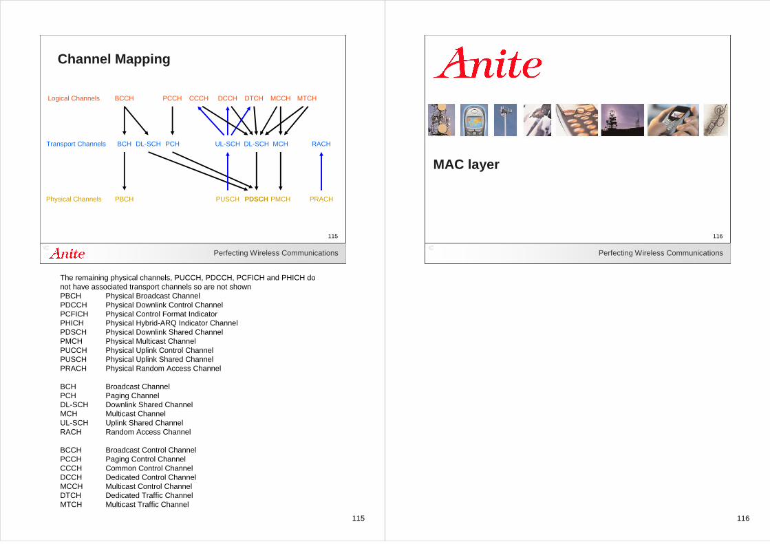
The remaining physical channels, PUCCH, PDCCH, PCFICH and PHICH do not have associated transport channels so are not shownPBCH Physical Broadcast ChannelPDCCH Physical Downlink Control ChannelPCFICH Physical Control Format IndicatorPHICH Physical Hybrid-ARQ Indicator ChannelPDSCH Physical Downlink Shared ChannelPMCH Physical Multicast ChannelPUCCH Physical Uplink Control ChannelPUSCH Physical Uplink Shared ChannelPRACH Physical Random Access Channel
BCH Broadcast ChannelPCH Paging ChannelDL-SCH Downlink Shared ChannelMCH Multicast ChannelUL-SCH Uplink Shared ChannelRACH Random Access Channel
BCCH Broadcast Control ChannelPCCH Paging Control Channel CCCH Common Control ChannelDCCH Dedicated Control ChannelMCCH Multicast Control ChannelDTCH Dedicated Traffic ChannelMTCH Multicast Traffic Channel
116
116Perfecting Wireless Communications
116
MAC layer
117
Perfecting Wireless Communications
117
MAC Layer
• Medium Access Control– Mapping (multiple) logical channels onto transport
channels– Managing the priorities of data flows– Prioritizing between different mobiles for uplink
transmission– Selecting transport formats (instantaneous data rate)– Selection of modulation scheme for the data– Support of Hybrid ARQ repetition process– Transfer of data (Transport Blocks) to the Physical
Layer every Transmission Time Interval (TTI)
Data is sent from the physical layer to the MAC layer in the form of transport channels. The MAC layer is responsible for mapping the transport channels onto logical channels and transmitting the data up to the RLC layer, and the reverse - receiving data on logical channels from the RLC layer and mapping that data onto transport channels for the physical layer. On those channels, MAC layer is also responsible for segmenting long messages from higher layers into blocks, and reassembling blocks from the physical layer into messages for the higher layers.
MAC layer is also responsible for selecting the transport formats used on the transport channels, and distinguishing between different UEs using the common channels.
118
Perfecting Wireless Communications
118
Transport Blocks
• Each Transport Channel transfers a Transport Block Set of 1 (or 2) Transport Blocks to Layer 1 each Transmission Time Interval
• TTI is fixed at 1ms for traffic and paging– TTI for BCH is 40ms
119
Perfecting Wireless Communications
119
Physical Layer
MAC
1 TTI (1ms)
Transport Block Size = xxx bits Number of Blocks = 1
Transport Block Sets
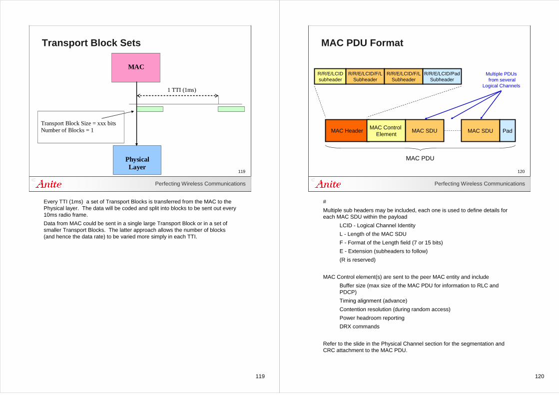
Every TTI (1ms) a set of Transport Blocks is transferred from the MAC to the Physical layer. The data will be coded and split into blocks to be sent out every 10ms radio frame.
Data from MAC could be sent in a single large Transport Block or in a set of smaller Transport Blocks. The latter approach allows the number of blocks (and hence the data rate) to be varied more simply in each TTI.
120
Perfecting Wireless Communications
120
MAC PDU Format
MAC Header MAC SDU
MAC PDU
R/R/E/LCIDsubheader
R/R/E/LCID/F/LSubheader
MAC SDU PadMAC Control
Element
R/R/E/LCID/F/LSubheader
R/R/E/LCID/PadSubheader
Multiple PDUsfrom several
Logical Channels
#
Multiple sub headers may be included, each one is used to define details for each MAC SDU within the payload
LCID - Logical Channel Identity
L - Length of the MAC SDU
F - Format of the Length field (7 or 15 bits)
E - Extension (subheaders to follow)
(R is reserved)
MAC Control element(s) are sent to the peer MAC entity and include
Buffer size (max size of the MAC PDU for information to RLC and PDCP)
Timing alignment (advance)
Contention resolution (during random access)
Power headroom reporting
DRX commands
Refer to the slide in the Physical Channel section for the segmentation and CRC attachment to the MAC PDU.
121
Perfecting Wireless Communications
121
MAC PDU Random Access Response
MAC Header MAC RAR
MAC PDU
E/T/R/R/BIsubheader
E/T/RAPIDSubheader
MAC RAR PadMAC RAR
E/T/RAPIDSubheader
Random Access Responseto several mobiles
#
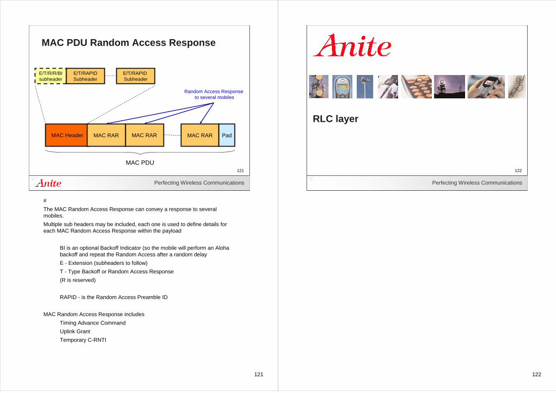
The MAC Random Access Response can convey a response to several mobiles.
Multiple sub headers may be included, each one is used to define details for each MAC Random Access Response within the payload
BI is an optional Backoff Indicator (so the mobile will perform an Aloha backoff and repeat the Random Access after a random delay
E - Extension (subheaders to follow)
T - Type Backoff or Random Access Response
(R is reserved)
RAPID - is the Random Access Preamble ID
MAC Random Access Response includes
Timing Advance Command
Uplink Grant
Temporary C-RNTI
122
122Perfecting Wireless Communications
122
RLC layer
123
Perfecting Wireless Communications
123
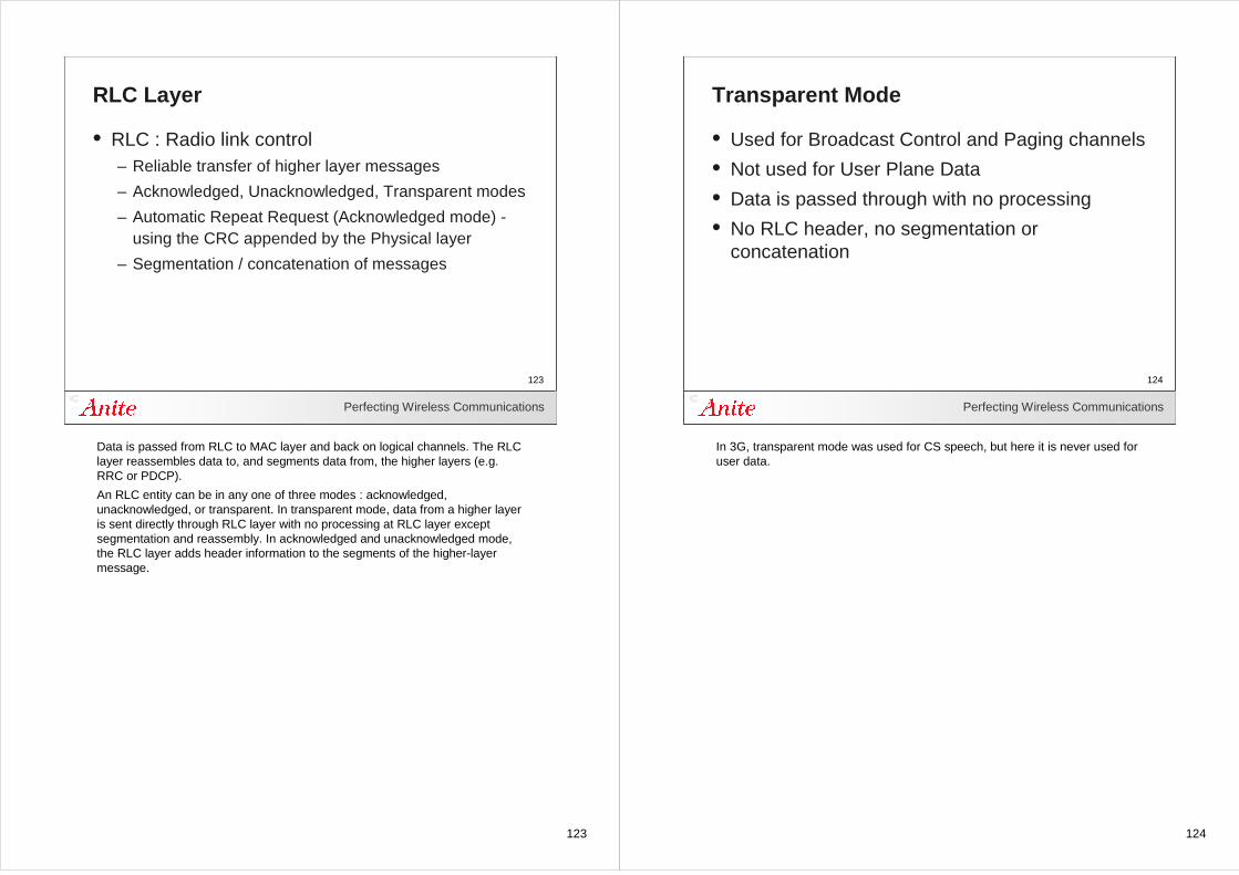
RLC Layer
• RLC : Radio link control– Reliable transfer of higher layer messages
– Acknowledged, Unacknowledged, Transparent modes
– Automatic Repeat Request (Acknowledged mode) -using the CRC appended by the Physical layer
– Segmentation / concatenation of messages
Data is passed from RLC to MAC layer and back on logical channels. The RLC layer reassembles data to, and segments data from, the higher layers (e.g. RRC or PDCP).
An RLC entity can be in any one of three modes : acknowledged, unacknowledged, or transparent. In transparent mode, data from a higher layer is sent directly through RLC layer with no processing at RLC layer except segmentation and reassembly. In acknowledged and unacknowledged mode, the RLC layer adds header information to the segments of the higher-layer message.
124
Perfecting Wireless Communications
124
Transparent Mode
• Used for Broadcast Control and Paging channels
• Not used for User Plane Data
• Data is passed through with no processing
• No RLC header, no segmentation or concatenation
In 3G, transparent mode was used for CS speech, but here it is never used for user data.
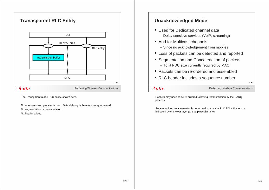
125
Perfecting Wireless Communications
125
Tranasparent RLC Entity
PDCP
Transmission buffer
MAC
RLC Tm SAP
RLC entity
The Transparent mode RLC entity, shown here.
No retransmission process is used. Data delivery is therefore not guaranteed.
No segmentation or concatenation.
No header added.
126
Perfecting Wireless Communications
126
Unacknowledged Mode
• Used for Dedicated channel data– Delay sensitive services (VoIP, streaming)
• And for Multicast channels– Since no acknowledgement from mobiles
• Loss of packets can be detected and reported
• Segmentation and Concatenation of packets– To fit PDU size currently required by MAC
• Packets can be re-ordered and assembled
• RLC header includes a sequence number
Packets may need to be re-ordered following retransmission by the HARQ process
Segmentation / concatenation is performed so that the RLC PDUs fit the size indicated by the lower layer (at that particular time).
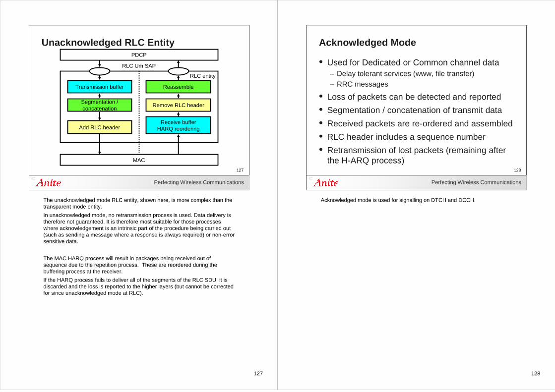
127
Perfecting Wireless Communications
127
Unacknowledged RLC EntityPDCP
Transmission buffer
Segmentation /concatenation
Add RLC header
MAC
Reassemble
Remove RLC header
Receive bufferHARQ reordering
RLC Um SAP
RLC entity
The unacknowledged mode RLC entity, shown here, is more complex than the transparent mode entity.
In unacknowledged mode, no retransmission process is used. Data delivery is therefore not guaranteed. It is therefore most suitable for those processes where acknowledgement is an intrinsic part of the procedure being carried out (such as sending a message where a response is always required) or non-error sensitive data.
The MAC HARQ process will result in packages being received out of sequence due to the repetition process. These are reordered during the buffering process at the receiver.
If the HARQ process fails to deliver all of the segments of the RLC SDU, it is discarded and the loss is reported to the higher layers (but cannot be corrected for since unacknowledged mode at RLC).
128
Perfecting Wireless Communications
128
Acknowledged Mode
• Used for Dedicated or Common channel data– Delay tolerant services (www, file transfer)– RRC messages
• Loss of packets can be detected and reported
• Segmentation / concatenation of transmit data
• Received packets are re-ordered and assembled
• RLC header includes a sequence number
• Retransmission of lost packets (remaining after the H-ARQ process)
Acknowledged mode is used for signalling on DTCH and DCCH.
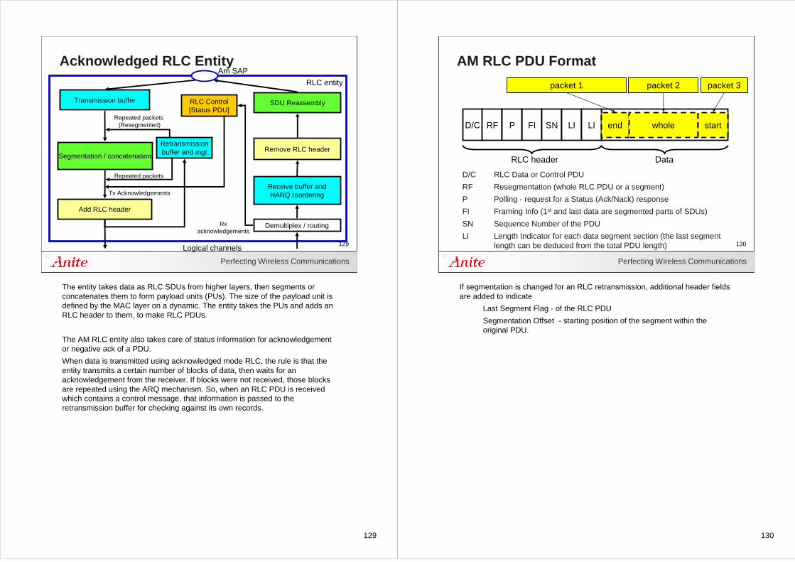
129
Perfecting Wireless Communications
129
Acknowledged RLC EntityRLC entity
Am SAP
Tx Acknowledgements
SDU Reassembly
Demultiplex / routing
Receive buffer andHARQ reordering
Rxacknowledgements
Retransmissionbuffer and mgtSegmentation / concatenation
Transmission buffer
Logical channels
Add RLC header
Remove RLC header
RLC Control[Status PDU]
Repeated packets (Resegmented)
Repeated packets
The entity takes data as RLC SDUs from higher layers, then segments or concatenates them to form payload units (PUs). The size of the payload unit is defined by the MAC layer on a dynamic. The entity takes the PUs and adds an RLC header to them, to make RLC PDUs.
The AM RLC entity also takes care of status information for acknowledgement or negative ack of a PDU.
When data is transmitted using acknowledged mode RLC, the rule is that the entity transmits a certain number of blocks of data, then waits for an acknowledgement from the receiver. If blocks were not received, those blocks are repeated using the ARQ mechanism. So, when an RLC PDU is received which contains a control message, that information is passed to the retransmission buffer for checking against its own records.
130
Perfecting Wireless Communications
130
AM RLC PDU Format
D/C RLC Data or Control PDU
RF Resegmentation (whole RLC PDU or a segment)
P Polling - request for a Status (Ack/Nack) response
FI Framing Info (1st and last data are segmented parts of SDUs)
SN Sequence Number of the PDU
LI Length Indicator for each data segment section (the last segmentlength can be deduced from the total PDU length)
D/C RF FIP
RLC header Data
SN LI LI end whole start
packet 1 packet 2 packet 3
If segmentation is changed for an RLC retransmission, additional header fields are added to indicate
Last Segment Flag - of the RLC PDU
Segmentation Offset - starting position of the segment within the original PDU.
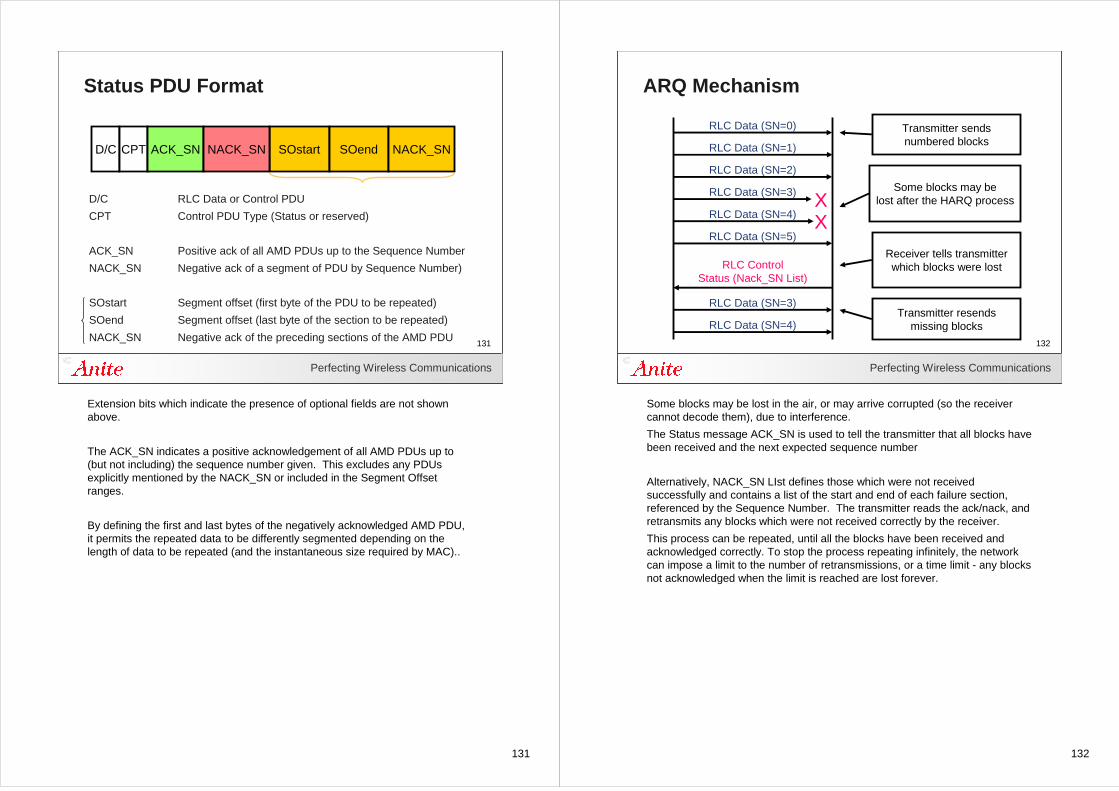
131
Perfecting Wireless Communications
131
Status PDU Format
D/C RLC Data or Control PDU
CPT Control PDU Type (Status or reserved)
ACK_SN Positive ack of all AMD PDUs up to the Sequence Number
NACK_SN Negative ack of a segment of PDU by Sequence Number)
SOstart Segment offset (first byte of the PDU to be repeated)
SOend Segment offset (last byte of the section to be repeated)
NACK_SN Negative ack of the preceding sections of the AMD PDU
D/C CPT SOstartACK_SN NACK_SN SOend NACK_SN
Extension bits which indicate the presence of optional fields are not shown above.
The ACK_SN indicates a positive acknowledgement of all AMD PDUs up to (but not including) the sequence number given. This excludes any PDUs explicitly mentioned by the NACK_SN or included in the Segment Offset ranges.
By defining the first and last bytes of the negatively acknowledged AMD PDU, it permits the repeated data to be differently segmented depending on the length of data to be repeated (and the instantaneous size required by MAC)..
132
Perfecting Wireless Communications
132
ARQ Mechanism
Transmitter sendsnumbered blocks
Some blocks may belost after the HARQ process
Receiver tells transmitterwhich blocks were lost
RLC Data (SN=0)
RLC Data (SN=1)
RLC Data (SN=2)
RLC Data (SN=3)
RLC Data (SN=4)
RLC Data (SN=5)
RLC ControlStatus (Nack_SN List)
RLC Data (SN=3)
RLC Data (SN=4)
XX
Transmitter resendsmissing blocks
Some blocks may be lost in the air, or may arrive corrupted (so the receiver cannot decode them), due to interference.
The Status message ACK_SN is used to tell the transmitter that all blocks have been received and the next expected sequence number
Alternatively, NACK_SN LIst defines those which were not received successfully and contains a list of the start and end of each failure section, referenced by the Sequence Number. The transmitter reads the ack/nack, and retransmits any blocks which were not received correctly by the receiver.
This process can be repeated, until all the blocks have been received and acknowledged correctly. To stop the process repeating infinitely, the network can impose a limit to the number of retransmissions, or a time limit - any blocks not acknowledged when the limit is reached are lost forever.
133
133Perfecting Wireless Communications
133
PDCP layer
134
Perfecting Wireless Communications
134
The PDCP Layer
• PDCP : Packet data convergence protocol– Supports user-plane services – Transfer of user data– IP Header compression and decompression (ROHC)– Integrity protection of NAS and RRC messages– Encryption of signalling and user data– Maintain 'lossless' data transfer during eNodeB
relocation (uses the Sequence Number in the PDCP Header)
The packet data convergence protocol (PDCP) layer is a layer 2 entity. It is an access stratum, user plane protocol.
It exists only to transmit user-plane information in the packet-switched domain. It also serves to handle the compression and decompression of the headers of the user data it carries. This is necessary because in some cases, the data header can up to three or four times the size of the payload. Only a single compression algorithm is defined in E-UTRAN.
Encryption is performed on signalling information (from RRC and NAS) and on data (user data and application level signalling from SIP and RTCP). This is notably different from the 2G and 3G architectures.
PDCP also serves to maintain lossless data transfer during cell relocation This is achieved using PDU sequence numbers, maintained by the PDCP layer. This is only done when the PDCP layer is attached to an acknowledged-mode RLC layer.
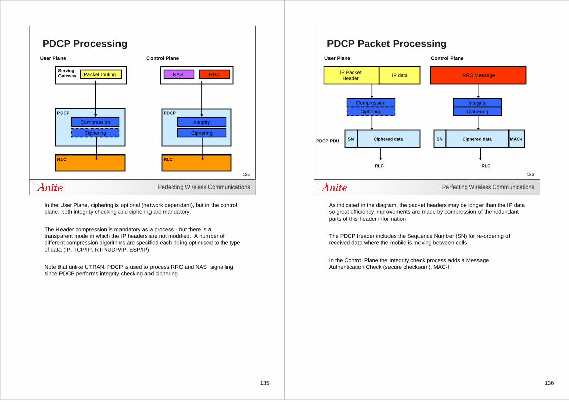
135
Perfecting Wireless Communications
135
PDCP Processing
Serving Gateway
PDCP
Compression
Ciphering
RLC
User Plane
PDCP
Integrity
Ciphering
Control Plane
RLC
NAS RRCPacket routing
In the User Plane, ciphering is optional (network dependant), but in the control plane, both integrity checking and ciphering are mandatory.
The Header compression is mandatory as a process - but there is a transparent mode in which the IP headers are not modified. A number of different compression algorithms are specified each being optimised to the type of data (IP, TCP/IP, RTP/UDP/IP, ESP/IP)
Note that unlike UTRAN, PDCP is used to process RRC and NAS signalling since PDCP performs integrity checking and ciphering
136
Perfecting Wireless Communications
136
PDCP Packet Processing
IP data
SN
Compression
Ciphering
RLC
User Plane Control Plane
IP Packet Header
Ciphered dataPDCP PDU
RRC Message
SN
Integrity
Ciphering
RLC
Ciphered data MAC-I
As indicated in the diagram, the packet headers may be longer than the IP data so great efficiency improvements are made by compression of the redundant parts of this header information
The PDCP header includes the Sequence Number (SN) for re-ordering of received data where the mobile is moving between cells
In the Control Plane the Integrity check process adds a Message Authentication Check (secure checksum), MAC-I
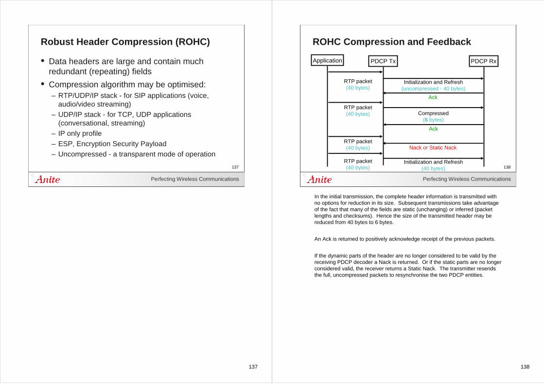
137
Perfecting Wireless Communications
137
Robust Header Compression (ROHC)
• Data headers are large and contain much redundant (repeating) fields
• Compression algorithm may be optimised:– RTP/UDP/IP stack - for SIP applications (voice,
audio/video streaming)– UDP/IP stack - for TCP, UDP applications
(conversational, streaming)– IP only profile – ESP, Encryption Security Payload– Uncompressed - a transparent mode of operation
138
Perfecting Wireless Communications
138
ROHC Compression and Feedback
PDCP Tx PDCP Rx
Compressed(6 bytes)
Ack
Initialization and Refresh(uncompressed - 40 bytes)
Application
RTP packet(40 bytes)
RTP packet(40 bytes)
RTP packet(40 bytes) Nack or Static Nack
Initialization and Refresh(40 bytes)
RTP packet(40 bytes)
Ack
In the initial transmission, the complete header information is transmitted with no options for reduction in its size. Subsequent transmissions take advantage of the fact that many of the fields are static (unchanging) or inferred (packet lengths and checksums). Hence the size of the transmitted header may be reduced from 40 bytes to 6 bytes.
An Ack is returned to positively acknowledge receipt of the previous packets.
If the dynamic parts of the header are no longer considered to be valid by the receiving PDCP decoder a Nack is returned. Or if the static parts are no longer considered valid, the receiver returns a Static Nack. The transmitter resends the full, uncompressed packets to resynchronise the two PDCP entities.
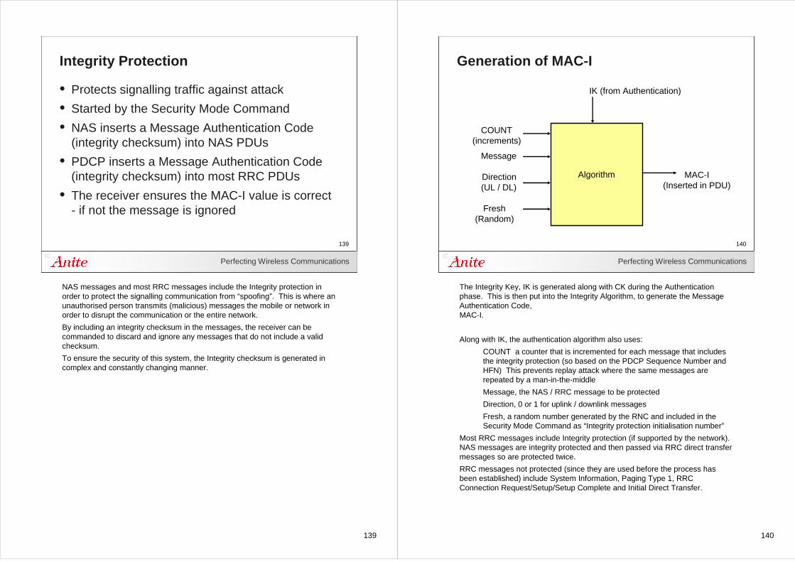
139
Perfecting Wireless Communications
139
Integrity Protection
• Protects signalling traffic against attack
• Started by the Security Mode Command
• NAS inserts a Message Authentication Code (integrity checksum) into NAS PDUs
• PDCP inserts a Message Authentication Code (integrity checksum) into most RRC PDUs
• The receiver ensures the MAC-I value is correct - if not the message is ignored
NAS messages and most RRC messages include the Integrity protection in order to protect the signalling communication from “spoofing”. This is where an unauthorised person transmits (malicious) messages the mobile or network in order to disrupt the communication or the entire network.
By including an integrity checksum in the messages, the receiver can be commanded to discard and ignore any messages that do not include a valid checksum.
To ensure the security of this system, the Integrity checksum is generated in complex and constantly changing manner.
140
Perfecting Wireless Communications
140
Generation of MAC-I
IK (from Authentication)
COUNT(increments)
Message
Direction(UL / DL)
Fresh(Random)
Algorithm MAC-I(Inserted in PDU)
The Integrity Key, IK is generated along with CK during the Authentication phase. This is then put into the Integrity Algorithm, to generate the Message Authentication Code, MAC-I.
Along with IK, the authentication algorithm also uses:
COUNT a counter that is incremented for each message that includes the integrity protection (so based on the PDCP Sequence Number and HFN) This prevents replay attack where the same messages are repeated by a man-in-the-middle
Message, the NAS / RRC message to be protected
Direction, 0 or 1 for uplink / downlink messages
Fresh, a random number generated by the RNC and included in the Security Mode Command as “Integrity protection initialisation number”
Most RRC messages include Integrity protection (if supported by the network). NAS messages are integrity protected and then passed via RRC direct transfer messages so are protected twice.
RRC messages not protected (since they are used before the process has been established) include System Information, Paging Type 1, RRCConnection Request/Setup/Setup Complete and Initial Direct Transfer.
141
Perfecting Wireless Communications
141
Ciphering
ScramblingGenerator
Data
CK
COUNTScramblingGenerator
Data
CK
Secure dataover air
COUNT
Pseudo random
Pseudo random
Ciphering may be a stream cipher (as illustrated) or a block ciphering algorithm
Ciphering in PDCP is performed thus. A ciphering algorithm is initially seeded with a Cipher Key (CK). This key is secret known only by the mobile and the network and is produced in the authentication procedure.
The algorithm will then produce a pseudo random sequence of great length (millions of years) but to ensure that the same section of the sequence is never re-used, COUNT is used to select different parts of the pseudo random sequence and is derived from the PDCP sequence number and HFN.
This sequence is then eXclusive ORed with the data to produce a very random looking stream for transmission over the air interface. It is then not possible for an interceptor to read the content of the data (or to work backwards to find the value of CK).
At the receiver the process is identical, the same CK and same COUNT are used to produce an exactly identical pseudo random sequence that is XORed with the same (ciphered) data bits. Clear data is produced since XOR function performed twice undoes the ciphering. This simple XOR function has the advantage that errors in the received data are not multiplied - 1 error in the received ciphered data results in only 1 error in the clear data stream.
142
142Perfecting Wireless Communications
142
Layer 3
143
143Perfecting Wireless Communications
143
RRC layer
144
Perfecting Wireless Communications
144
RRC Layer Tasks
• RRC : Radio resource control– System information broadcasting– Paging of idle-mode mobiles– Cell selection and reselection– Establishing and maintaining RRC connection– Management of the radio resources for transfer of
signalling and user data– Transfer of NAS messages– Control of handovers– Measurement reporting– Power control
RRC is the 'big brother' entity which controls all the signalling between the UE and the network (EPC). The RRC entity controls all the NAS signalling and mobility of connected UEs. It has control SAPs to all the other E-UTRAN entities (MAC, RLC, PDCP and the physical layer).
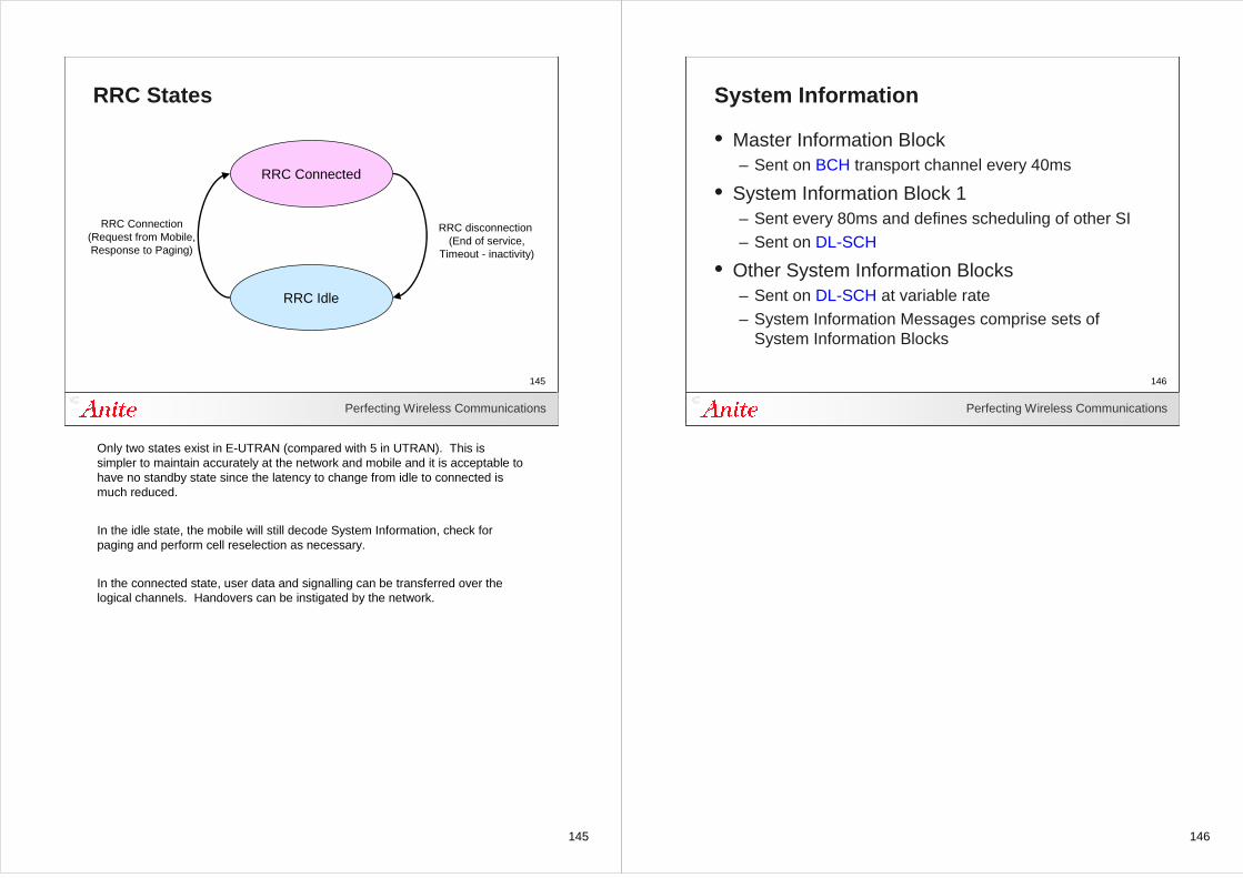
145
Perfecting Wireless Communications
145
RRC States
RRC Connected
RRC Idle
RRC Connection(Request from Mobile,Response to Paging)
RRC disconnection (End of service,
Timeout - inactivity)
Only two states exist in E-UTRAN (compared with 5 in UTRAN). This is simpler to maintain accurately at the network and mobile and it is acceptable to have no standby state since the latency to change from idle to connected is much reduced.
In the idle state, the mobile will still decode System Information, check for paging and perform cell reselection as necessary.
In the connected state, user data and signalling can be transferred over the logical channels. Handovers can be instigated by the network.
146
Perfecting Wireless Communications
146
System Information
• Master Information Block – Sent on BCH transport channel every 40ms
• System Information Block 1– Sent every 80ms and defines scheduling of other SI– Sent on DL-SCH
• Other System Information Blocks– Sent on DL-SCH at variable rate– System Information Messages comprise sets of
System Information Blocks
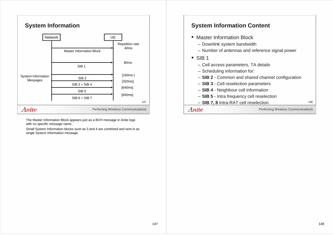
147
Perfecting Wireless Communications
147
System Information
Network UE
Master Information Block
SIB 2
SIB 3 + SIB 4
SIB 5
SIB 6 + SIB 7
SIB 1
40ms
80ms
[160ms ]
[320ms]
[640ms]
[640ms]
Repetition rate
System Information Messages
The Master Information Block appears just as a BCH message in Anite logs with no specific message name.
Small System Information blocks such as 3 and 4 are combined and sent in as single System Information message.
148
Perfecting Wireless Communications
148
System Information Content
• Master Information Block– Downlink system bandwidth– Number of antennas and reference signal power
• SIB 1– Cell access parameters, TA details– Scheduling information for:– SIB 2 - Common and shared channel configuration– SIB 3 - Cell reselection parameters– SIB 4 - Neighbour cell information– SIB 5 - Intra frequency cell reselection– SIB 7, 8 Intra-RAT cell reselection
149
149Perfecting Wireless Communications
149
RRC Procedures
150
Perfecting Wireless Communications
150
Random Access Procedure
• Initial procedure to update mobile timing synchronisation and transmit power
• Provides uplink resource scheduling
• Precedes RRC and NAS procedures:– RRC Connection (for Attach, TA update, PS session)– Handover to another EUTRAN cell– In Active state, following long DRX period (for PS
session)
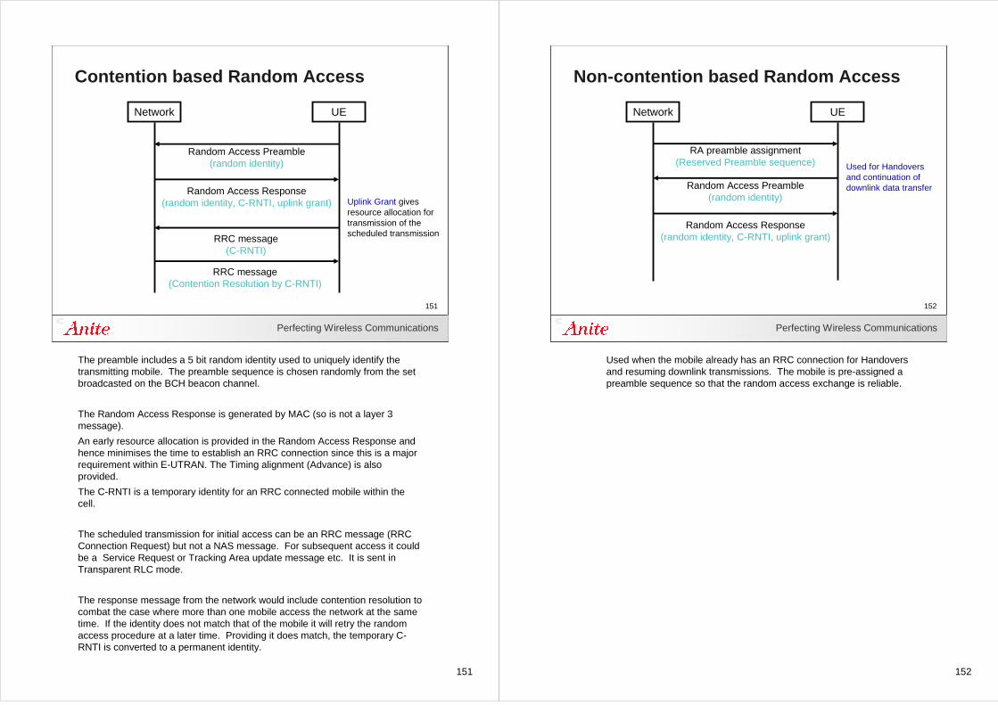
151
Perfecting Wireless Communications
151
Contention based Random Access
Network UE
Random Access Preamble(random identity)
Random Access Response(random identity, C-RNTI, uplink grant)
RRC message(C-RNTI)
RRC message(Contention Resolution by C-RNTI)
Uplink Grant gives resource allocation for transmission of the scheduled transmission
The preamble includes a 5 bit random identity used to uniquely identify the transmitting mobile. The preamble sequence is chosen randomly from the set broadcasted on the BCH beacon channel.
The Random Access Response is generated by MAC (so is not a layer 3 message).
An early resource allocation is provided in the Random Access Response and hence minimises the time to establish an RRC connection since this is a major requirement within E-UTRAN. The Timing alignment (Advance) is also provided.
The C-RNTI is a temporary identity for an RRC connected mobile within the cell.
The scheduled transmission for initial access can be an RRC message (RRC Connection Request) but not a NAS message. For subsequent access it could be a Service Request or Tracking Area update message etc. It is sent in Transparent RLC mode.
The response message from the network would include contention resolution to combat the case where more than one mobile access the network at the same time. If the identity does not match that of the mobile it will retry the random access procedure at a later time. Providing it does match, the temporary C-RNTI is converted to a permanent identity.
152
Perfecting Wireless Communications
152
Non-contention based Random Access
Network UE
Random Access Preamble(random identity)
Random Access Response(random identity, C-RNTI, uplink grant)
RA preamble assignment(Reserved Preamble sequence) Used for Handovers
and continuation of downlink data transfer
Used when the mobile already has an RRC connection for Handoversand resuming downlink transmissions. The mobile is pre-assigned a preamble sequence so that the random access exchange is reliable.
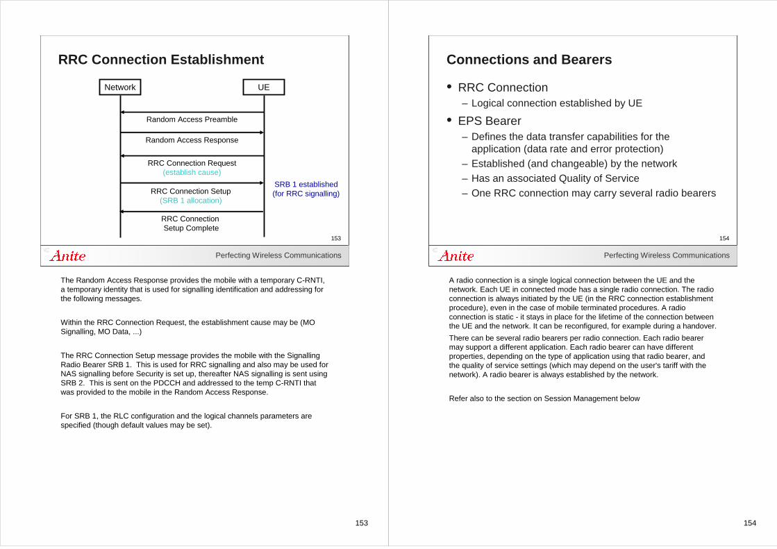
153
Perfecting Wireless Communications
153
RRC Connection Establishment
Network UE
Random Access Preamble
Random Access Response
RRC Connection Request(establish cause)
RRC Connection Setup(SRB 1 allocation)
RRC Connection Setup Complete
SRB 1 established(for RRC signalling)
The Random Access Response provides the mobile with a temporary C-RNTI, a temporary identity that is used for signalling identification and addressing for the following messages.
Within the RRC Connection Request, the establishment cause may be (MO Signalling, MO Data, ...)
The RRC Connection Setup message provides the mobile with the Signalling Radio Bearer SRB 1. This is used for RRC signalling and also may be used for NAS signalling before Security is set up, thereafter NAS signalling is sent using SRB 2. This is sent on the PDCCH and addressed to the temp C-RNTI that was provided to the mobile in the Random Access Response.
For SRB 1, the RLC configuration and the logical channels parameters are specified (though default values may be set).
154
Perfecting Wireless Communications
154
Connections and Bearers
• RRC Connection– Logical connection established by UE
• EPS Bearer– Defines the data transfer capabilities for the
application (data rate and error protection)– Established (and changeable) by the network– Has an associated Quality of Service– One RRC connection may carry several radio bearers
A radio connection is a single logical connection between the UE and the network. Each UE in connected mode has a single radio connection. The radio connection is always initiated by the UE (in the RRC connection establishment procedure), even in the case of mobile terminated procedures. A radio connection is static - it stays in place for the lifetime of the connection between the UE and the network. It can be reconfigured, for example during a handover.
There can be several radio bearers per radio connection. Each radio bearer may support a different application. Each radio bearer can have different properties, depending on the type of application using that radio bearer, and the quality of service settings (which may depend on the user's tariff with the network). A radio bearer is always established by the network.
Refer also to the section on Session Management below
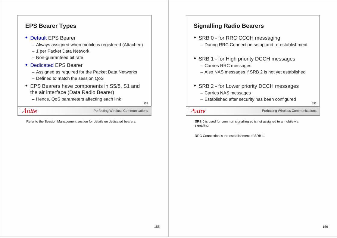
155
Perfecting Wireless Communications
155
EPS Bearer Types
• Default EPS Bearer– Always assigned when mobile is registered (Attached)– 1 per Packet Data Network– Non-guaranteed bit rate
• Dedicated EPS Bearer– Assigned as required for the Packet Data Networks– Defined to match the session QoS
• EPS Bearers have components in S5/8, S1 and the air interface (Data Radio Bearer)– Hence, QoS parameters affecting each link
Refer to the Session Management section for details on dedicated bearers.
156
Perfecting Wireless Communications
156
Signalling Radio Bearers
• SRB 0 - for RRC CCCH messaging – During RRC Connection setup and re-establishment
• SRB 1 - for High priority DCCH messages– Carries RRC messages– Also NAS messages if SRB 2 is not yet established
• SRB 2 - for Lower priority DCCH messages– Carries NAS messages– Established after security has been configured
SRB 0 is used for common signalling so is not assigned to a mobile via signalling
RRC Connection is the establishment of SRB 1.
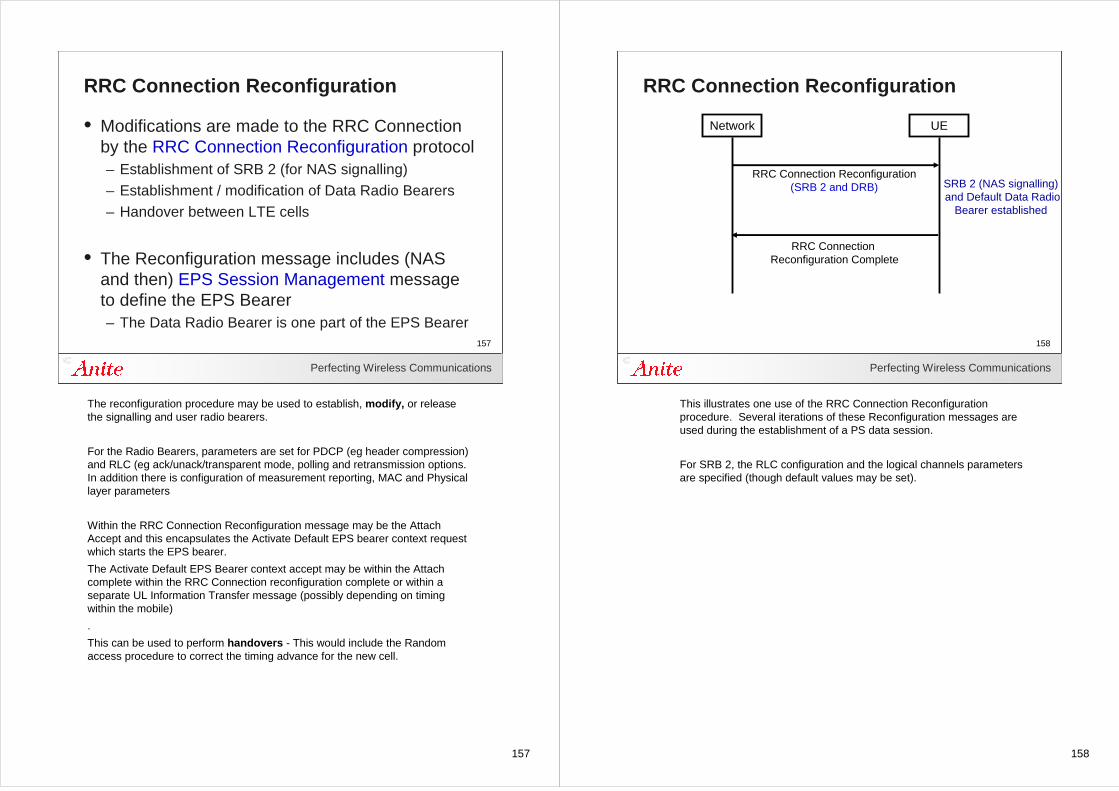
157
Perfecting Wireless Communications
157
RRC Connection Reconfiguration
• Modifications are made to the RRC Connection by the RRC Connection Reconfiguration protocol– Establishment of SRB 2 (for NAS signalling) – Establishment / modification of Data Radio Bearers– Handover between LTE cells
• The Reconfiguration message includes (NAS and then) EPS Session Management message to define the EPS Bearer– The Data Radio Bearer is one part of the EPS Bearer
The reconfiguration procedure may be used to establish, modify, or release the signalling and user radio bearers.
For the Radio Bearers, parameters are set for PDCP (eg header compression) and RLC (eg ack/unack/transparent mode, polling and retransmission options. In addition there is configuration of measurement reporting, MAC and Physical layer parameters
Within the RRC Connection Reconfiguration message may be the Attach Accept and this encapsulates the Activate Default EPS bearer context request which starts the EPS bearer.
The Activate Default EPS Bearer context accept may be within the Attach complete within the RRC Connection reconfiguration complete or within a separate UL Information Transfer message (possibly depending on timing within the mobile)
.
This can be used to perform handovers - This would include the Random access procedure to correct the timing advance for the new cell.
158
Perfecting Wireless Communications
158
RRC Connection Reconfiguration
Network UE
RRC Connection Reconfiguration(SRB 2 and DRB)
RRC Connection Reconfiguration Complete
SRB 2 (NAS signalling)and Default Data Radio
Bearer established
This illustrates one use of the RRC Connection Reconfiguration procedure. Several iterations of these Reconfiguration messages are used during the establishment of a PS data session.
For SRB 2, the RLC configuration and the logical channels parameters are specified (though default values may be set).
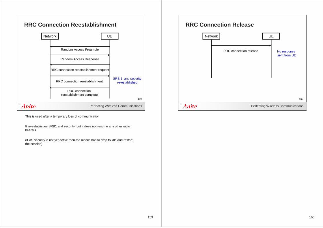
159
Perfecting Wireless Communications
159
RRC Connection Reestablishment
Network UE
Random Access Preamble
Random Access Response
RRC connection reestablishment request
RRC connection reestablishment
RRC connection reestablishment complete
SRB 1 and securityre-established
This is used after a temporary loss of communication
It re-establishes SRB1 and security, but it does not resume any other radio bearers
(If AS security is not yet active then the mobile has to drop to idle and restart the session)
160
Perfecting Wireless Communications
160
RRC Connection Release
Network UE
RRC connection release No response sent from UE
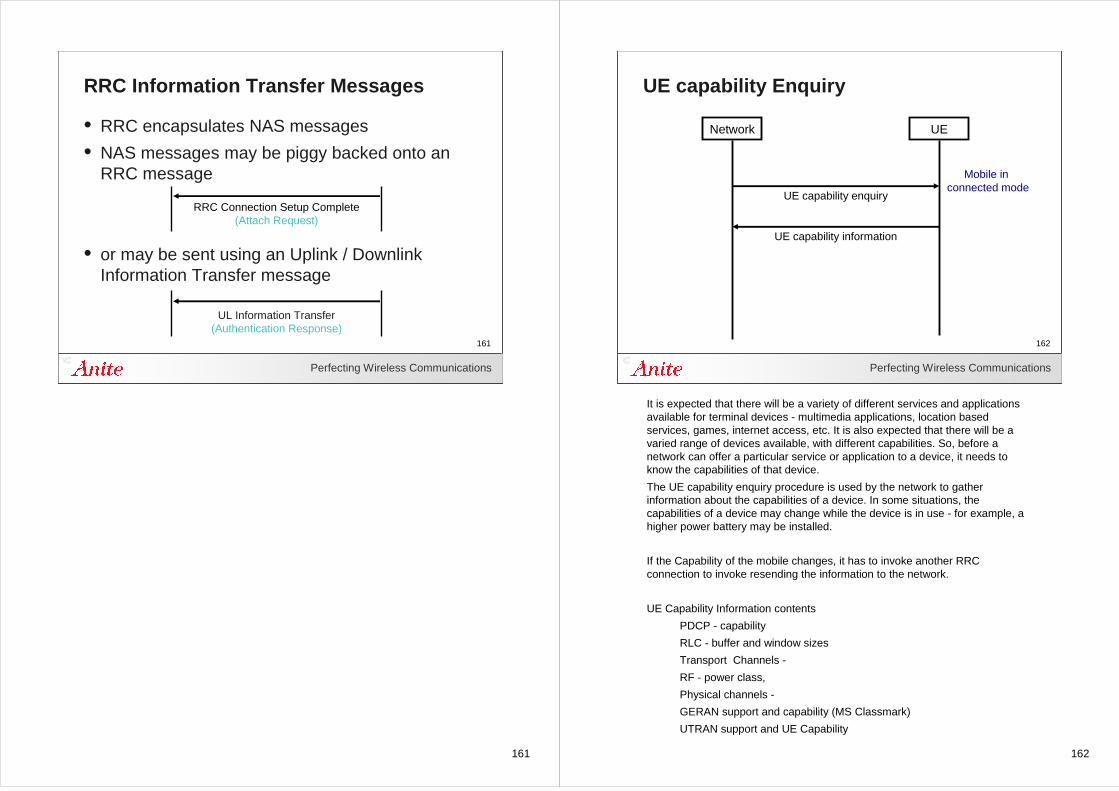
161
Perfecting Wireless Communications
161
RRC Information Transfer Messages
• RRC encapsulates NAS messages
• NAS messages may be piggy backed onto an RRC message
• or may be sent using an Uplink / Downlink Information Transfer message
RRC Connection Setup Complete(Attach Request)
UL Information Transfer(Authentication Response)
162
Perfecting Wireless Communications
162
UE capability Enquiry
Network UE
UE capability enquiry
UE capability information
Mobile in connected mode
It is expected that there will be a variety of different services and applications available for terminal devices - multimedia applications, location based services, games, internet access, etc. It is also expected that there will be a varied range of devices available, with different capabilities. So, before a network can offer a particular service or application to a device, it needs to know the capabilities of that device.
The UE capability enquiry procedure is used by the network to gather information about the capabilities of a device. In some situations, the capabilities of a device may change while the device is in use - for example, a higher power battery may be installed.
If the Capability of the mobile changes, it has to invoke another RRC connection to invoke resending the information to the network.
UE Capability Information contents
PDCP - capability
RLC - buffer and window sizes
Transport Channels -
RF - power class,
Physical channels -
GERAN support and capability (MS Classmark)
UTRAN support and UE Capability
163
163Perfecting Wireless Communications
163
EPS Mobility Management
164
Perfecting Wireless Communications
164
EPS Mobility Management
• Registration (Attach)– Assignment of the Default EPS Bearer and IP address
• Periodic Updating
• Control plane functions related to the user and session management
• Authentication
• Control of ciphering and integrity checking
• Tracking of mobile location (in idle mode)
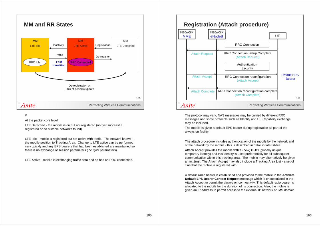
165
Perfecting Wireless Communications
165
MM and RR States
MM
LTE Idle
RRC Idle
MM
LTE Active
RRC Connected
MM
LTE DetachedInactivity
Traffic
Registration
De-register
De-registration or lack of periodic update
Fasttransition
#
At the packet core level:
LTE Detached - the mobile is on but not registered (not yet successful registered or no suitable networks found)
LTE Idle - mobile is registered but not active with traffic. The network knows the mobile position to Tracking Area. Change to LTE active can be performed very quickly and any EPS bearers that had been established are maintained so there is no exchange of session parameters (inc QoS parameters).
LTE Active - mobile is exchanging traffic data and so has an RRC connection.
166
Perfecting Wireless Communications
166
Registration (Attach procedure)
Network UE
RRC Connection reconfiguration complete(Attach Complete)
RRC Connection
AuthenticationSecurity
NetworkeNodeB
RRC Connection reconfiguration(Attach Accept)
RRC Connection Setup Complete(Attach Request)
NetworkMME
Attach Complete
Attach Accept
Attach Request
Default EPS Bearer
The protocol may vary, NAS messages may be carried by different RRC messages and some protocols such as Identity and UE Capability exchange may be included.
The mobile is given a default EPS bearer during registration as part of the always on facility.
The attach procedure includes authentication of the mobile by the network and of the network by the mobile - this is described in detail in later slides
Attach Accept provides the mobile with a (new) GUTI (globally unique temporary identity) and this identity is used preferentially for all subsequent communication within this tracking area. The mobile may alternatively be given an m_tmsi. The Attach Accept may also include a Tracking Area List - a set of TAs that the mobile is registered with.
A default radio bearer is established and provided to the mobile in the Activate Default EPS Bearer Context Request message which is encapsulated in the Attach Accept to permit the always on connectivity. This default radio bearer is allocated to the mobile for the duration of its connection. Also, the mobile is given an IP address to permit access to the external IP network or IMS domain.
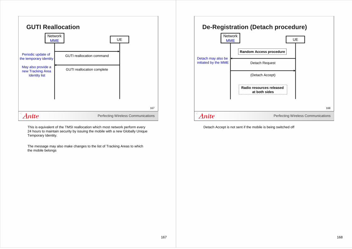
167
Perfecting Wireless Communications
167
GUTI Reallocation
Network UE
GUTI reallocation command
GUTI reallocation complete
NetworkMME
Periodic update of the temporary identity
May also provide anew Tracking Area
Identity list
This is equivalent of the TMSI reallocation which most network perform every 24 hours to maintain security by issuing the mobile with a new Globally Unique Temporary Identity.
The message may also make changes to the list of Tracking Areas to which the mobile belongs
168
Perfecting Wireless Communications
168
De-Registration (Detach procedure)
Network UE
(Detach Accept)
Radio resources released at both sides
Detach Request
Random Access procedure
NetworkMME
Detach may also beinitiated by the MME
Detach Accept is not sent if the mobile is being switched off
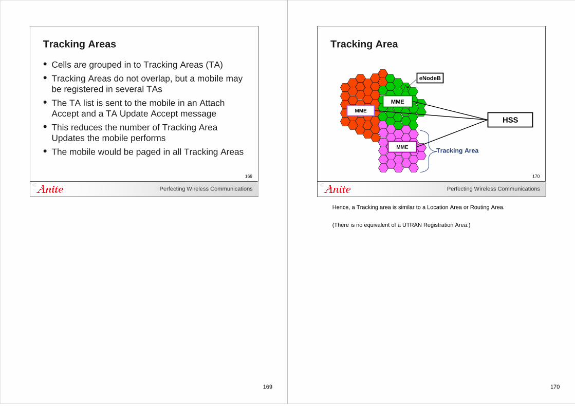
169
Perfecting Wireless Communications
169
Tracking Areas
• Cells are grouped in to Tracking Areas (TA)
• Tracking Areas do not overlap, but a mobile may be registered in several TAs
• The TA list is sent to the mobile in an Attach Accept and a TA Update Accept message
• This reduces the number of Tracking Area Updates the mobile performs
• The mobile would be paged in all Tracking Areas
170
Perfecting Wireless Communications
170
Tracking Area
eNodeB
HSS
MME
MME
MMETracking Area
Hence, a Tracking area is similar to a Location Area or Routing Area.
(There is no equivalent of a UTRAN Registration Area.)
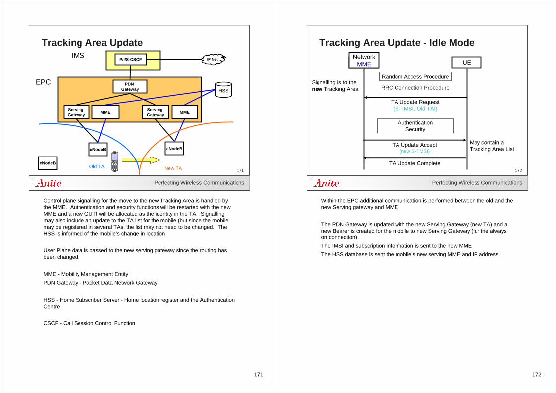
171
Perfecting Wireless Communications
171
Tracking Area Update
P/I/S-CSCF
PDN Gateway
Serving Gateway
MME
eNodeB
IMS
EPC
IP Net
HSS
eNodeB
eNodeBOld TA New TA
Serving Gateway
MME
Control plane signalling for the move to the new Tracking Area is handled by the MME. Authentication and security functions will be restarted with the new MME and a new GUTI will be allocated as the identity in the TA. Signalling may also include an update to the TA list for the mobile (but since the mobile may be registered in several TAs, the list may not need to be changed. The HSS is informed of the mobile’s change in location
User Plane data is passed to the new serving gateway since the routing has been changed.
MME - Mobility Management Entity
PDN Gateway - Packet Data Network Gateway
HSS - Home Subscriber Server - Home location register and the Authentication Centre
CSCF - Call Session Control Function
172
Perfecting Wireless Communications
172
Tracking Area Update - Idle Mode
Network UE
Random Access Procedure
RRC Connection Procedure
TA Update Request(S-TMSI, Old TAI)
TA Update Accept(new S-TMSI)
TA Update Complete
Signalling is to the new Tracking Area
NetworkMME
AuthenticationSecurity
May contain a Tracking Area List
Within the EPC additional communication is performed between the old and the new Serving gateway and MME
The PDN Gateway is updated with the new Serving Gateway (new TA) and a new Bearer is created for the mobile to new Serving Gateway (for the always on connection)
The IMSI and subscription information is sent to the new MME
The HSS database is sent the mobile’s new serving MME and IP address
173
173Perfecting Wireless Communications
173
Handovers
174
Perfecting Wireless Communications
174
Mobility in Active Mode
• Handover (Packet Switched)
• Decision made by the eNodeB based on measurement reports
• ... or from the eNodeB alone for load balancing
• Make before break so minimal interruption
• Packets forwarded to permit data repetition
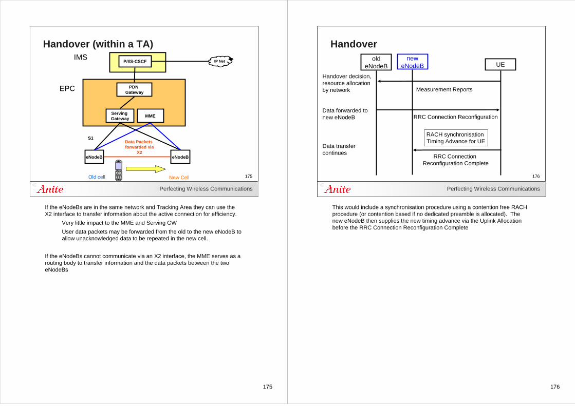
175
Perfecting Wireless Communications
175
Handover (within a TA)
P/I/S-CSCF
PDN Gateway
eNodeB
IMS
EPC
IP Net
eNodeB
Old cell New Cell
Serving Gateway
MME
Data Packets forwarded via
X2
S1
If the eNodeBs are in the same network and Tracking Area they can use the X2 interface to transfer information about the active connection for efficiency.
Very little impact to the MME and Serving GW
User data packets may be forwarded from the old to the new eNodeB to allow unacknowledged data to be repeated in the new cell.
If the eNodeBs cannot communicate via an X2 interface, the MME serves as a routing body to transfer information and the data packets between the two eNodeBs
176
Perfecting Wireless Communications
176
Handover old
eNodeB UE
RRC Connection Reconfiguration
RRC Connection Reconfiguration Complete
Handover decision, resource allocation by network
Data forwarded tonew eNodeB
neweNodeB
Data transfer continues
RACH synchronisation Timing Advance for UE
Measurement Reports
This would include a synchronisation procedure using a contention free RACH procedure (or contention based if no dedicated preamble is allocated). The new eNodeB then supplies the new timing advance via the Uplink Allocation before the RRC Connection Reconfiguration Complete
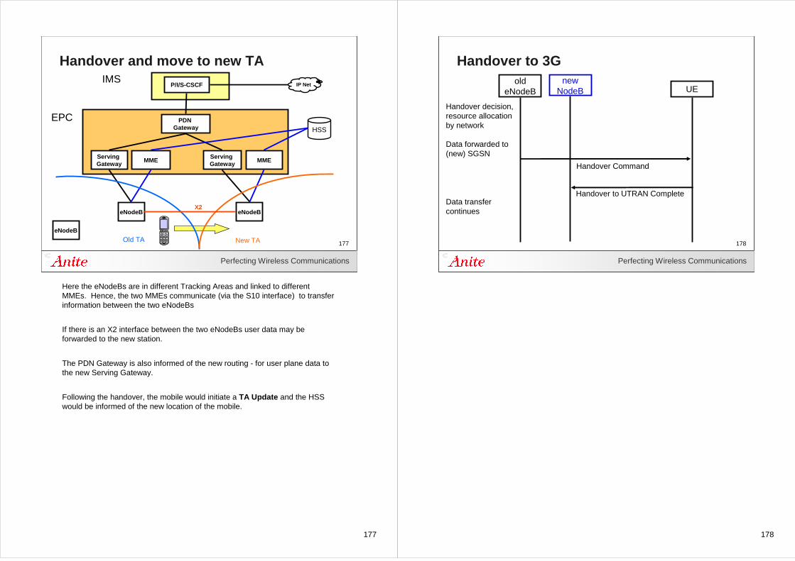
177
Perfecting Wireless Communications
177
Handover and move to new TA
P/I/S-CSCF
PDN Gateway
Serving Gateway
MME
eNodeB
IMS
EPC
IP Net
HSS
eNodeB
eNodeB
Old TA New TA
Serving Gateway
MME
X2
Here the eNodeBs are in different Tracking Areas and linked to different MMEs. Hence, the two MMEs communicate (via the S10 interface) to transfer information between the two eNodeBs
If there is an X2 interface between the two eNodeBs user data may be forwarded to the new station.
The PDN Gateway is also informed of the new routing - for user plane data to the new Serving Gateway.
Following the handover, the mobile would initiate a TA Update and the HSS would be informed of the new location of the mobile.
178
Perfecting Wireless Communications
178
Handover to 3Gold
eNodeB UE
Handover Command
Handover to UTRAN Complete
Handover decision, resource allocation by network
Data forwarded to(new) SGSN
newNodeB
Data transfer continues
179
179Perfecting Wireless Communications
179
Security
180
Perfecting Wireless Communications
180
Security - Mobile to Network
• IP Multimedia Sub-system (IMS)– Integrity protection for SIP signalling
• Evolved Packet Core– Ciphering and Integrity for NAS signalling
• E-UTRAN (PDCP)– Ciphering and Integrity for RRC signalling – Ciphering for user plane data (and SIP signalling)
• Security keys– Produced during the authentication exchange– Different security keys used for each process
NAS messages are encrypted within EPC and then again within PDCP when encapsulated in an RRC message
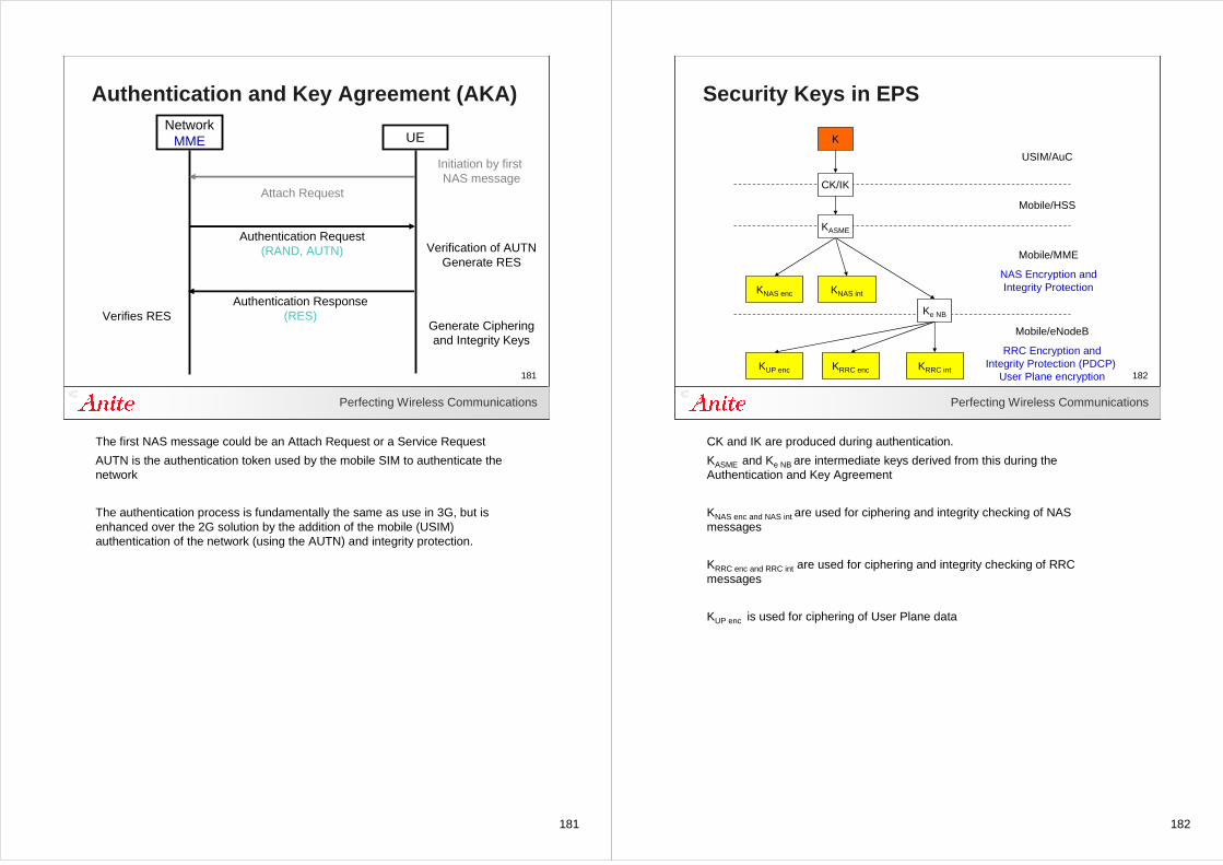
181
Perfecting Wireless Communications
181
Authentication and Key Agreement (AKA)Network
MME UE
Attach Request
Authentication Request(RAND, AUTN)
Authentication Response(RES)
Verification of AUTNGenerate RES
Generate Cipheringand Integrity Keys
Verifies RES
Initiation by first NAS message
The first NAS message could be an Attach Request or a Service Request
AUTN is the authentication token used by the mobile SIM to authenticate the network
The authentication process is fundamentally the same as use in 3G, but is enhanced over the 2G solution by the addition of the mobile (USIM) authentication of the network (using the AUTN) and integrity protection.
182
Perfecting Wireless Communications
182
Security Keys in EPS
K
KNAS enc KNAS int
KUP enc KRRC enc KRRC int
Mobile/eNodeB
RRC Encryption andIntegrity Protection (PDCP)
User Plane encryption
Mobile/MME
NAS Encryption andIntegrity Protection
Mobile/HSS
USIM/AuC
CK/IK
KASME
Ke NB
CK and IK are produced during authentication.
KASME and Ke NB are intermediate keys derived from this during the Authentication and Key Agreement
KNAS enc and NAS int are used for ciphering and integrity checking of NAS messages
KRRC enc and RRC int are used for ciphering and integrity checking of RRC messages
KUP enc is used for ciphering of User Plane data
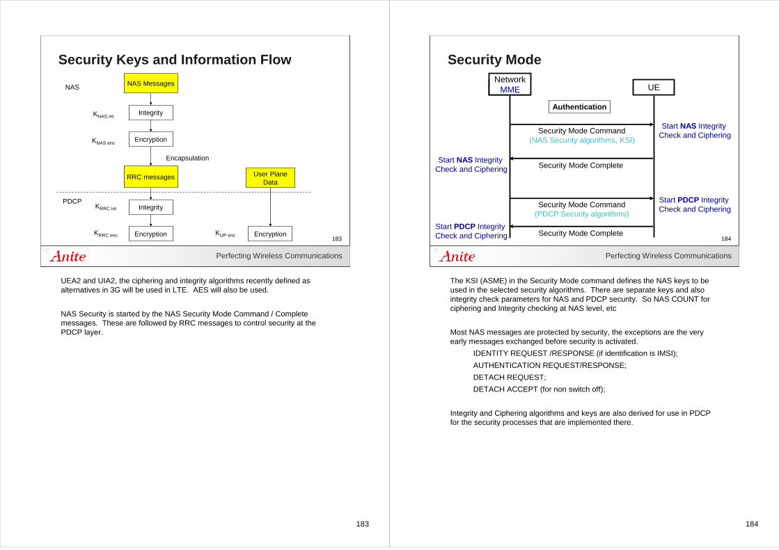
183
Perfecting Wireless Communications
183
Security Keys and Information Flow
NAS Messages
RRC messages
KUP encKRRC enc
KRRC int
Integrity
Encryption
User PlaneData
Integrity
Encryption Encryption
KNAS enc
KNAS int
Encapsulation
PDCP
NAS
UEA2 and UIA2, the ciphering and integrity algorithms recently defined as alternatives in 3G will be used in LTE. AES will also be used.
NAS Security is started by the NAS Security Mode Command / Complete messages. These are followed by RRC messages to control security at the PDCP layer.
184
Perfecting Wireless Communications
184
Security Mode
Network UE
Security Mode Command(NAS Security algorithms, KSI)
Security Mode Complete
Start NAS Integrity Check and Ciphering
Authentication
NetworkMME
Start NAS Integrity Check and Ciphering
Security Mode Command(PDCP Security algorithms)
Security Mode Complete
Start PDCP Integrity Check and Ciphering
Start PDCP Integrity Check and Ciphering
The KSI (ASME) in the Security Mode command defines the NAS keys to be used in the selected security algorithms. There are separate keys and also integrity check parameters for NAS and PDCP security. So NAS COUNT for ciphering and Integrity checking at NAS level, etc
Most NAS messages are protected by security, the exceptions are the very early messages exchanged before security is activated.
IDENTITY REQUEST /RESPONSE (if identification is IMSI);
AUTHENTICATION REQUEST/RESPONSE;
DETACH REQUEST;
DETACH ACCEPT (for non switch off);
Integrity and Ciphering algorithms and keys are also derived for use in PDCP for the security processes that are implemented there.
185
185Perfecting Wireless Communications
185
EPS Session Management (ESM)
186
Perfecting Wireless Communications
186
EPS Bearer Activation
• EPS Bearers are activated for transfer of user data
• Default EPS Bearer allocated during Attach (always on)
• Further dedicated EPS Bearers may be allocated subsequently
• PDP (IP) address is allocated by the Network
• Quality of Service is negotiated
Session Management functions
The mobile must previously have done a PS Attach
A different Quality of Service profile may be requested for each EPS Bearer.
E-mail that can tolerate lengthy response times
Interactive applications cannot tolerate delay and demand a very high level of throughput
Establishment of the EPS bearers is therefore equivalent to establishment of PDP Context in 2G/3G.
.
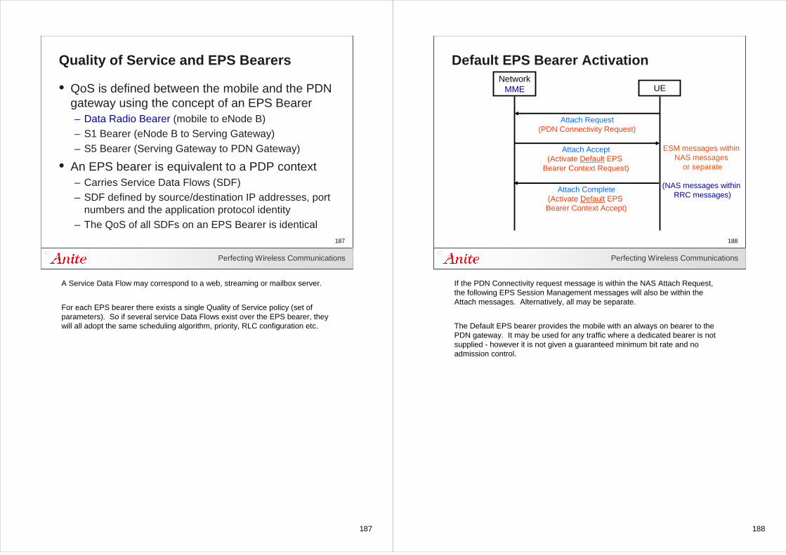
187
Perfecting Wireless Communications
187
Quality of Service and EPS Bearers
• QoS is defined between the mobile and the PDN gateway using the concept of an EPS Bearer– Data Radio Bearer (mobile to eNode B)– S1 Bearer (eNode B to Serving Gateway)– S5 Bearer (Serving Gateway to PDN Gateway)
• An EPS bearer is equivalent to a PDP context– Carries Service Data Flows (SDF)– SDF defined by source/destination IP addresses, port
numbers and the application protocol identity– The QoS of all SDFs on an EPS Bearer is identical
A Service Data Flow may correspond to a web, streaming or mailbox server.
For each EPS bearer there exists a single Quality of Service policy (set of parameters). So if several service Data Flows exist over the EPS bearer, they will all adopt the same scheduling algorithm, priority, RLC configuration etc.
188
Perfecting Wireless Communications
188
Default EPS Bearer Activation
UE
Attach Request(PDN Connectivity Request)
Attach Accept(Activate Default EPS
Bearer Context Request)
Attach Complete(Activate Default EPS Bearer Context Accept)
ESM messages within NAS messages
or separate
(NAS messages within RRC messages)
NetworkMME
If the PDN Connectivity request message is within the NAS Attach Request, the following EPS Session Management messages will also be within the Attach messages. Alternatively, all may be separate.
The Default EPS bearer provides the mobile with an always on bearer to the PDN gateway. It may be used for any traffic where a dedicated bearer is not supplied - however it is not given a guaranteed minimum bit rate and no admission control.
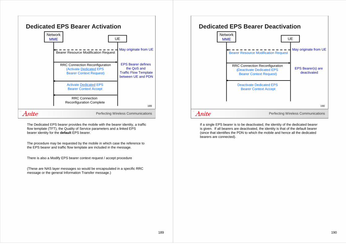
189
Perfecting Wireless Communications
189
Dedicated EPS Bearer Activation
UE
May originate from UE
NetworkMME
Bearer Resource Modification Request
EPS Bearer defines the QoS and
Traffic Flow Templatebetween UE and PDN
RRC Connection Reconfiguration(Activate Dedicated EPS Bearer Context Request)
RRC Connection Reconfiguration Complete
Activate Dedicated EPSBearer Context Accept
The Dedicated EPS bearer provides the mobile with the bearer identity, a traffic flow template (TFT), the Quality of Service parameters and a linked EPS bearer identity for the default EPS bearer.
The procedure may be requested by the mobile in which case the reference to the EPS bearer and traffic flow template are included in the message.
There is also a Modify EPS bearer context request / accept procedure
(These are NAS layer messages so would be encapsulated in a specific RRC message or the general Information Transfer message.)
190
Perfecting Wireless Communications
190
Dedicated EPS Bearer Deactivation
UE
Bearer Resource Modification Request
RRC Connection Reconfiguration(Deactivate Dedicated EPS
Bearer Context Request)
Deactivate Dedicated EPS Bearer Context Accept
EPS Bearer(s) are deactivated
May originate from UE
NetworkMME
If a single EPS bearer is to be deactivated, the identity of the dedicated bearer is given. If all bearers are deactivated, the identity is that of the default bearer (since that identifies the PDN to which the mobile and hence all the dedicated bearers are connected).
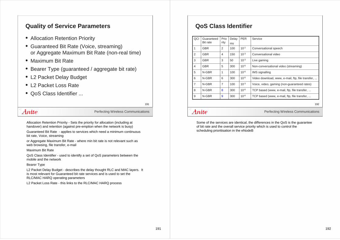
191
Perfecting Wireless Communications
191
Quality of Service Parameters
• Allocation Retention Priority
• Guaranteed Bit Rate (Voice, streaming)or Aggregate Maximum Bit Rate (non-real time)
• Maximum Bit Rate
• Bearer Type (guaranteed / aggregate bit rate)
• L2 Packet Delay Budget
• L2 Packet Loss Rate
• QoS Class Identifier ...
Allocation Retention Priority - Sets the priority for allocation (including at handover) and retention (against pre-emption when the network is busy)
Guaranteed Bit Rate - applies to services which need a minimum continuous bit rate, Voice, streaming
or Aggregate Maximum Bit Rate - where min bit rate is not relevant such as web browsing, file transfer, e-mail
Maximum Bit Rate
QoS Class Identifier - used to identify a set of QoS parameters between the mobile and the network
Bearer Type
L2 Packet Delay Budget - describes the delay thought RLC and MAC layers. It is most relevant for Guaranteed bit rate services and is used to set the RLC/MAC HARQ operating parameters
L2 Packet Loss Rate - this links to the RLC/MAC HARQ process
192
Perfecting Wireless Communications
192
QoS Class Identifier
TCP based (www, e-mail, ftp, file transfer, ...10-63009N-GBR9
TCP based (www, e-mail, ftp, file transfer, ...10-63008N-GBR8
Voice, video, gaming (non-guaranteed rates)10-31007N-GBR7
Video download, www, e-mail, ftp, file transfer, ...10-63006N-GBR6
IMS signalling10-61001N-GBR5
Non-conversational video (streaming)10-63005GBR4
Live gaming10-3503GBR3
Conversational video10-31504GBR2
Conversational speech10-21002GBR1
ServicePERDelay
ms
Priority
Guaranteed Bit rate
QCI
Some of the services are identical, the differences in the QoS is the guarantee of bit rate and the overall service priority which is used to control the scheduling prioritisation in the eNodeB
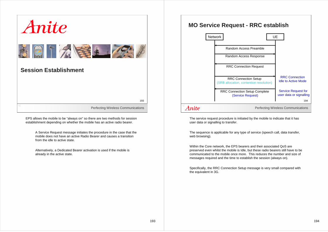
193
193Perfecting Wireless Communications
193
Session Establishment
EPS allows the mobile to be “always on” so there are two methods for session establishment depending on whether the mobile has an active radio bearer.
A Service Request message initiates the procedure in the case that the mobile does not have an active Radio Bearer and causes a transition from the idle to active state.
Alternatively, a Dedicated Bearer activation is used if the mobile is already in the active state.
194
Perfecting Wireless Communications
194
MO Service Request - RRC establish
Network UE
Random Access Preamble
Random Access Response
RRC Connection Request
RRC Connection Setup(SRB allocation, contention resolution)
RRC Connection Setup Complete(Service Request)
RRC ConnectionIdle to Active Mode
Service Request for user data or signalling
The service request procedure is initiated by the mobile to indicate that it has user data or signalling to transfer.
The sequence is applicable for any type of service (speech call, data transfer, web browsing).
Within the Core network, the EPS bearers and their associated QoS are preserved even whilst the mobile is Idle, but these radio bearers still have to be communicated to the mobile once more. This reduces the number and size of messages required and the time to establish the session (always on).
Specifically, the RRC Connection Setup message is very small compared with the equivalent in 3G.
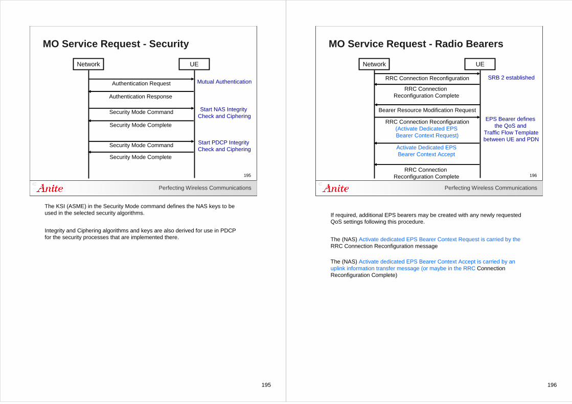
195
Perfecting Wireless Communications
195
MO Service Request - Security
Network UE
Authentication Request
Authentication Response
Security Mode Command
Security Mode Complete
Start NAS Integrity Check and Ciphering
Mutual Authentication
Security Mode Command
Security Mode Complete
Start PDCP Integrity Check and Ciphering
The KSI (ASME) in the Security Mode command defines the NAS keys to be used in the selected security algorithms.
Integrity and Ciphering algorithms and keys are also derived for use in PDCP for the security processes that are implemented there.
196
Perfecting Wireless Communications
196
MO Service Request - Radio Bearers
Network UE
Bearer Resource Modification Request
EPS Bearer defines the QoS and
Traffic Flow Templatebetween UE and PDN
RRC Connection Reconfiguration(Activate Dedicated EPS Bearer Context Request)
RRC Connection Reconfiguration Complete
Activate Dedicated EPSBearer Context Accept
RRC Connection Reconfiguration
RRC Connection Reconfiguration Complete
SRB 2 established
If required, additional EPS bearers may be created with any newly requested QoS settings following this procedure.
The (NAS) Activate dedicated EPS Bearer Context Request is carried by the RRC Connection Reconfiguration message
The (NAS) Activate dedicated EPS Bearer Context Accept is carried by an uplink information transfer message (or maybe in the RRC Connection Reconfiguration Complete)
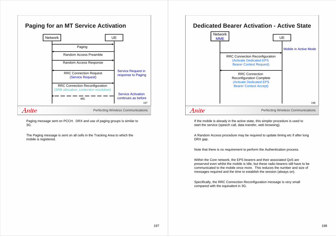
197
Perfecting Wireless Communications
197
Paging for an MT Service Activation
Network UE
Random Access Preamble
Random Access Response
RRC Connection Request(Service Request)
RRC Connection Reconfiguration(SRB allocation, contention resolution)
etc
Paging
Service Activation continues as before
Service Request in response to Paging
Paging message sent on PCCH. DRX and use of paging groups is similar to 3G.
The Paging message is sent on all cells in the Tracking Area to which the mobile is registered.
198
Perfecting Wireless Communications
198
Dedicated Bearer Activation - Active State
Network UE
Mobile in Active Mode
NetworkMME
RRC Connection Reconfiguration Complete(Activate Dedicated EPSBearer Context Accept)
RRC Connection Reconfiguration(Activate Dedicated EPS Bearer Context Request)
If the mobile is already in the active state, this simpler procedure is used to start the service (speech call, data transfer, web browsing).
A Random Access procedure may be required to update timing etc if after long DRX gap.
Note that there is no requirement to perform the Authentication process.
Within the Core network, the EPS bearers and their associated QoS are preserved even whilst the mobile is Idle, but these radio bearers still have to be communicated to the mobile once more. This reduces the number and size of messages required and the time to establish the session (always on).
Specifically, the RRC Connection Reconfiguration message is very small compared with the equivalent in 3G.
199
199Perfecting Wireless Communications
199
Services
200
Perfecting Wireless Communications
200
Services
• Multimedia telephony (VoIP, video telephony)
• Multimedia broadcast and multicast (MBMS)
• Push to talk over Cellular (PoC)
• Presence
P/I/S-CSCF
MGCF
MGW
PSTN
IP Net
IMS
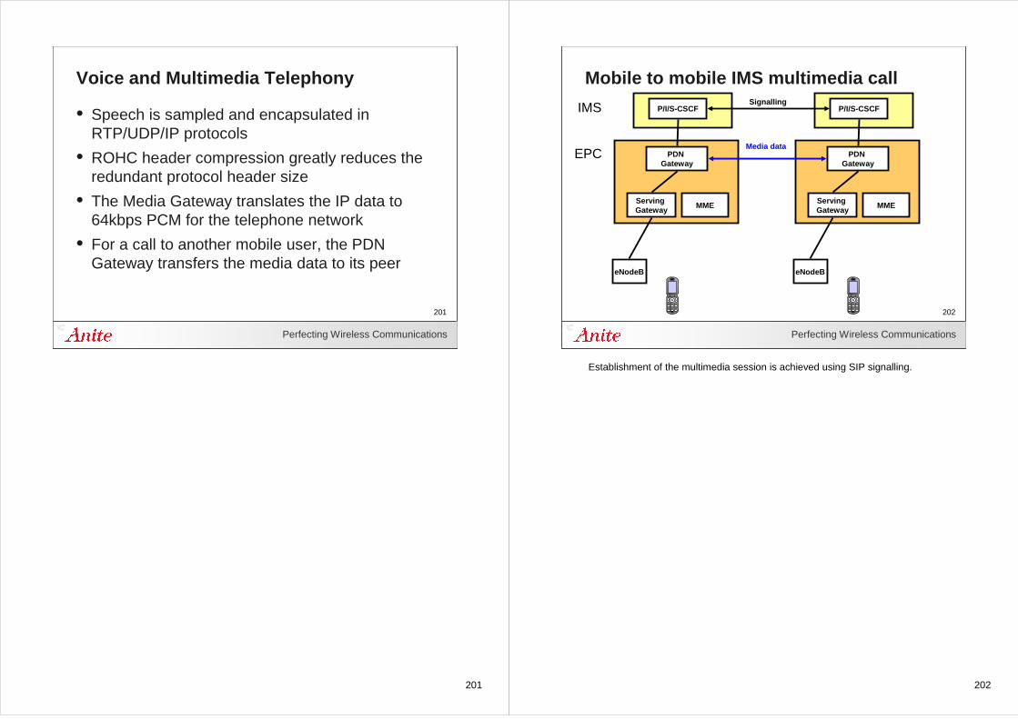
201
Perfecting Wireless Communications
201
Voice and Multimedia Telephony
• Speech is sampled and encapsulated in RTP/UDP/IP protocols
• ROHC header compression greatly reduces the redundant protocol header size
• The Media Gateway translates the IP data to 64kbps PCM for the telephone network
• For a call to another mobile user, the PDN Gateway transfers the media data to its peer
202
Perfecting Wireless Communications
202
Mobile to mobile IMS multimedia call
P/I/S-CSCF
PDN Gateway
eNodeB
IMS
EPC
Serving Gateway
MME
P/I/S-CSCF
PDN Gateway
eNodeB
Serving Gateway
MME
Media data
Signalling
Establishment of the multimedia session is achieved using SIP signalling.
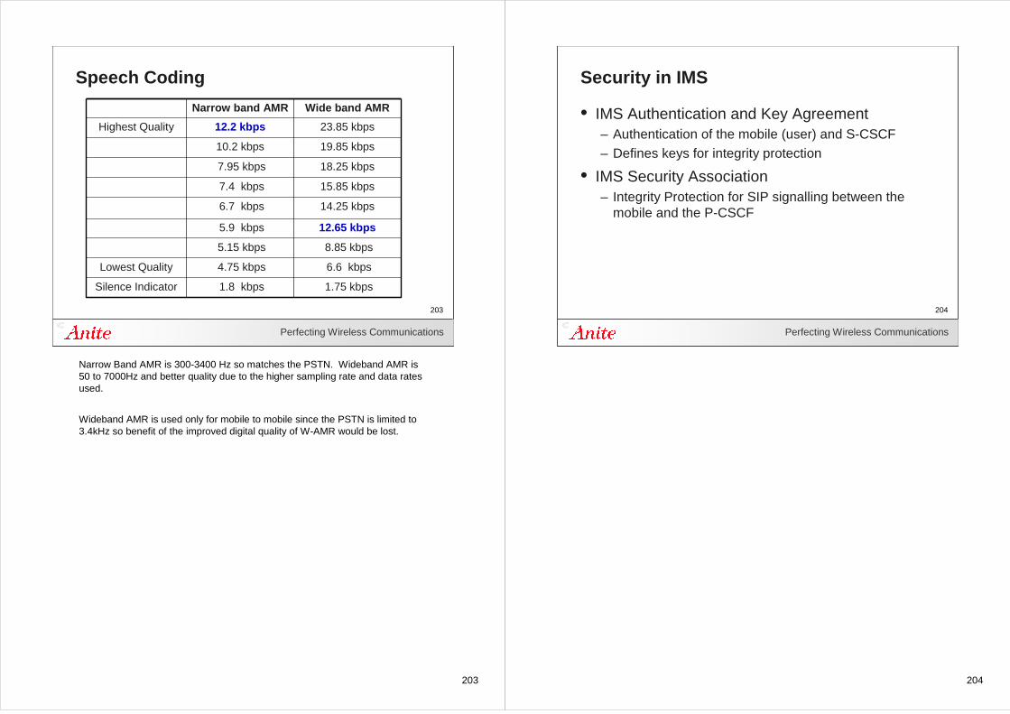
203
Perfecting Wireless Communications
203
Speech Coding
Silence Indicator
Lowest Quality
Highest Quality
1.8 kbps
4.75 kbps
5.15 kbps
5.9 kbps
6.7 kbps
7.4 kbps
7.95 kbps
10.2 kbps
12.2 kbps
Narrow band AMR
1.75 kbps
6.6 kbps
8.85 kbps
12.65 kbps
14.25 kbps
15.85 kbps
18.25 kbps
19.85 kbps
23.85 kbps
Wide band AMR
Narrow Band AMR is 300-3400 Hz so matches the PSTN. Wideband AMR is 50 to 7000Hz and better quality due to the higher sampling rate and data rates used.
Wideband AMR is used only for mobile to mobile since the PSTN is limited to 3.4kHz so benefit of the improved digital quality of W-AMR would be lost.
204
Perfecting Wireless Communications
204
Security in IMS
• IMS Authentication and Key Agreement– Authentication of the mobile (user) and S-CSCF– Defines keys for integrity protection
• IMS Security Association– Integrity Protection for SIP signalling between the
mobile and the P-CSCF
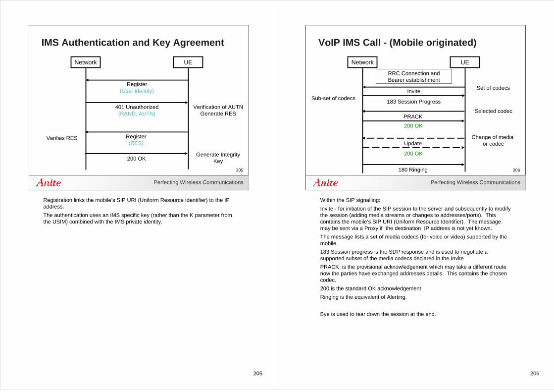
205
Perfecting Wireless Communications
205
IMS Authentication and Key Agreement
Network UE
Register(User identity)
401 Unauthorized(RAND, AUTN)
Register(RES)
Verification of AUTNGenerate RES
Generate IntegrityKey
Verifies RES
200 OK
Registration links the mobile’s SIP URI (Uniform Resource Identifier) to the IP address.
The authentication uses an IMS specific key (rather than the K parameter from the USIM) combined with the IMS private identity.
206
Perfecting Wireless Communications
206
VoIP IMS Call - (Mobile originated)
Network UE
Invite
183 Session Progress
PRACK
200 OK
Update
200 OK
180 Ringing
RRC Connection andBearer establishment
Set of codecs
Sub-set of codecs
Selected codec
Change of media or codec
Within the SIP signalling:
Invite - for initiation of the SIP session to the server and subsequently to modify the session (adding media streams or changes to addresses/ports). This contains the mobile’s SIP URI (Uniform Resource Identifier). The message may be sent via a Proxy if the destination IP address is not yet known.
The message lists a set of media codecs (for voice or video) supported by the mobile.
183 Session progress is the SDP response and is used to negotiate a supported subset of the media codecs declared in the Invite
PRACK is the provisional acknowledgement which may take a different route now the parties have exchanged addresses details. This contains the chosen codec.
200 is the standard OK acknowledgement
Ringing is the equivalent of Alerting.
Bye is used to tear down the session at the end.
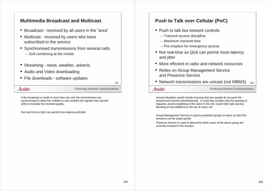
207
Perfecting Wireless Communications
207
Multimedia Broadcast and Multicast
• Broadcast - received by all users in the “area”
• Multicast - received by users who have subscribed to the service
• Synchronised transmissions from several cells– Soft combining at the mobile
• Streaming - news, weather, adverts
• Audio and Video downloading
• File downloads - software updates
If the broadcast is made in more than one cell, the transmissions are synchronised to allow the mobiles to soft combine the signals from several cells to increase the received quality.
Not real time so QoS can permit more latency and jitter
208
Perfecting Wireless Communications
208
Push to Talk over Cellular (PoC)
• Push to talk but network controls – Transmit access discipline– Maximum transmit time– Pre-emption for emergency access
• Not real-time so QoS can permit more latency and jitter
• More efficient in radio and network resources
• Relies on Group Management Serviceand Presence Service
• Network transmissions are unicast (not MBMS)
Access discipline would include ensuring that two people do not push the pressel and transmit simultaneously. It could also include rules for queuing of requests, priority weighting of the users in the call, round robin type access, blocking of new additions to the set of users, etc.
Group Management Service is used to predefine groups of users so that PoC sessions can be setup quickly
Presence Service is used to determine which users of the above group are currently involved in the session.
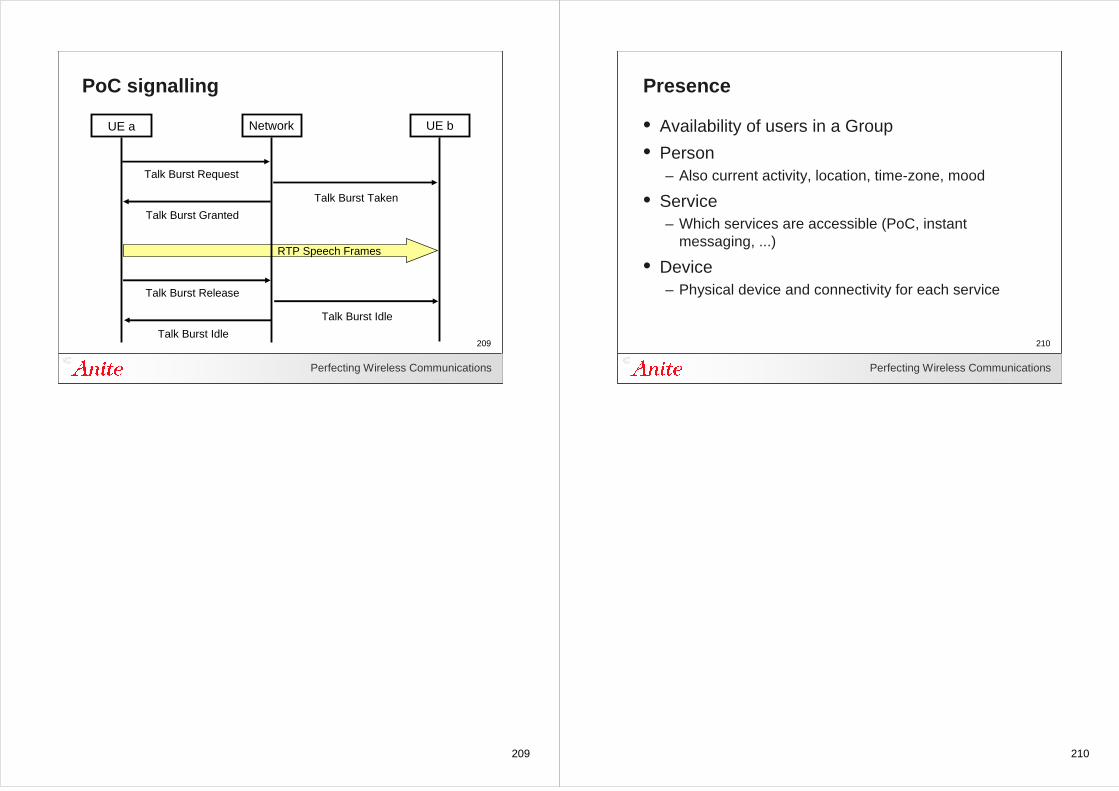
209
Perfecting Wireless Communications
209
PoC signalling
Network UE b
Talk Burst Taken
Talk Burst Request
RTP Speech Frames
UE a
Talk Burst Granted
Talk Burst Idle
Talk Burst Release
Talk Burst Idle
210
Perfecting Wireless Communications
210
Presence
• Availability of users in a Group
• Person– Also current activity, location, time-zone, mood
• Service– Which services are accessible (PoC, instant
messaging, ...)
• Device– Physical device and connectivity for each service
211
Perfecting Wireless Communications
211
Reference Material
• Evolved Packet System - Pierre Lescuyer, Thierry Lucidarme
• LTE and the Evolution to 4G Wireless - Agilent
• The UMTS Long Term Evolution: From Theory to Practice - Stefania Sesia, Issam Toufik, Matthew Baker
• LTE for UMTS: OFDMA and SC-FDMA Based Radio Access - Harri Holma and Antti Toskala
212
Perfecting Wireless Communications
212
Specifications
• E-UTRA/E-UTRAN description TS 36.300
• Non-Access Stratum TS 24.301
• Radio Resource Control TS 36.331
• Packet Data Convergence Protocol TS 36.323
• Radio Link Control TS 36.322
• Medium Access Control TS 36.321
• Physical Layer Procedures TS 36.213
• Multiplexing and Channel Coding TS 36.212
• Physical Channels and Modulation TS 36.211
213
AbbreviationsARQ Automatic Repeat Request
AS Access Stratum
BCCH Broadcast Control Channel
BCH Broadcast Channel
CMC Connection Mobility Control
CP Cyclic Prefix
C-RNTI Cell RNTI
CQI Channel Quality Indicator
CRC Cyclic Redundancy Check
CSG Closed Subscriber Group
DCCH Dedicated Control Channel
DRB Data Radio Bearer
DTCH Dedicated Traffic Channel
ECM EPS Connection Management
EMM EPS Mobility Management
eNB E-UTRAN NodeB
EPC Evolved Packet Core
EPS Evolved Packet System
E-UTRA Evolved UTRA
E-UTRAN Evolved UTRAN
FDD Frequency Division Duplex
FDM Frequency Division Multiplexing
HARQ Hybrid ARQ
LTE Long Term Evolution
MAC Medium Access Control
MBMS Multimedia Broadcast Multicast Service
MCCH Multicast Control Channel
MCE Multi-cell/multicast Coordination Entity
MCH Multicast Channel
MCS Modulation and Coding Scheme
MIB Master Information Block
MIMO Multiple Input Multiple Output
MME Mobility Management Entity
MTCH MBMS Traffic Channel
NAS Non-Access Stratum
OFDM Orthogonal Frequency Division Multiplexing
OFDMA Orthogonal Frequency Division Multiple Access
P-GW PDN Gateway
P-RNTI Paging RNTI
PAPR Peak-to-Average Power Ratio
PBCH Physical Broadcast CHannel
PCCH Paging Control Channel
PCFICH Physical Control Format Indicator CHannel
PCH Paging Channel
PCI Physical Cell Identifier
PDCCH Physical Downlink Control CHannel
PDSCH Physical Downlink Shared CHannel
PDCP Packet Data Convergence Protocol
PDU Protocol Data Unit
PHICH Physical Hybrid ARQ Indicator CHannel
PHY Physical layer
PLMN Public Land Mobile Network
PMCH Physical Multicast CHannel
PRACH Physical Random Access CHannel
PRB Physical Resource Block
PUCCH Physical Uplink Control CHannel
PUSCH Physical Uplink Shared CHannel
QAM Quadrature Amplitude Modulation
QCI QoS Class Identifier
QoS Quality of Service
RA-RNTI Random Access RNTI
RAC Radio Admission Control
RACH Random Access Channel
RB Radio Bearer
RLC Radio Link Control
RNC Radio Network Controller
RNTI Radio Network Temporary Identifier
ROHC Robust Header Compression
RRC Radio Resource Control
RRM Radio Resource Management
RU Resource Unit
S-GW Serving Gateway
S1-MME S1 for the control plane
SC-RNTI System Information Change RNTI
SI System Information
SIB System Information Block
SI-RNTI System Information RNTI
S1-U S1 for the user plane
SAE System Architecture Evolution
SAP Service Access Point
SC-FDMA Single Carrier – Frequency Division Multiple Access
SCH Synchronization Channel
SDF Service Data Flow
SDU Service Data Unit
SFN System Frame Number
SR Scheduling Request
SRB Signalling Radio Bearer
SU Scheduling Unit
TA Tracking Area
TB Transport Block
TCP Transmission Control Protocol
TDD Time Division Duplex
TFT Traffic Flow Template
TM Transparent Mode
TNL Transport Network Layer
TTI Transmission Time Interval
UE User Equipment
UL Uplink
UM Un-acknowledge Mode
UMTS Universal Mobile Telecommunication System
U-plane User plane
UTRA Universal Terrestrial Radio Access
UTRAN Universal Terrestrial Radio Access Network
UpPTS Uplink Pilot Time Slot
VRB Virtual Resource Block
X2-C X2-Control plane
X2-U X2-User plane
214
214Perfecting Wireless Communications
214
The End
Recommended