S

Contents
S Top Level Design
S Interfacing the SD
card with Nexys4
S PCM vs. PWM
signals
S Seven Segment Clock
(Timer)
S Further Design
Implementations

Design
0011101011…
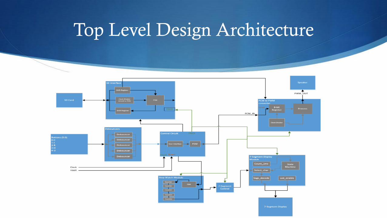
Top Level Design Architecture
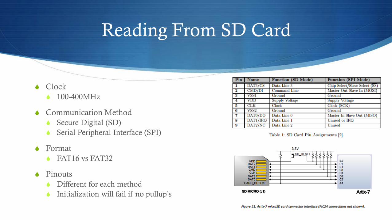
Reading From SD Card
S Clock
S 100-400MHz
S Communication Method
S Secure Digital (SD)
S Serial Peripheral Interface (SPI)
S Format
S FAT16 vs FAT32
S Pinouts
S Different for each method
S Initialization will fail if no pullup’s
SD Protocol
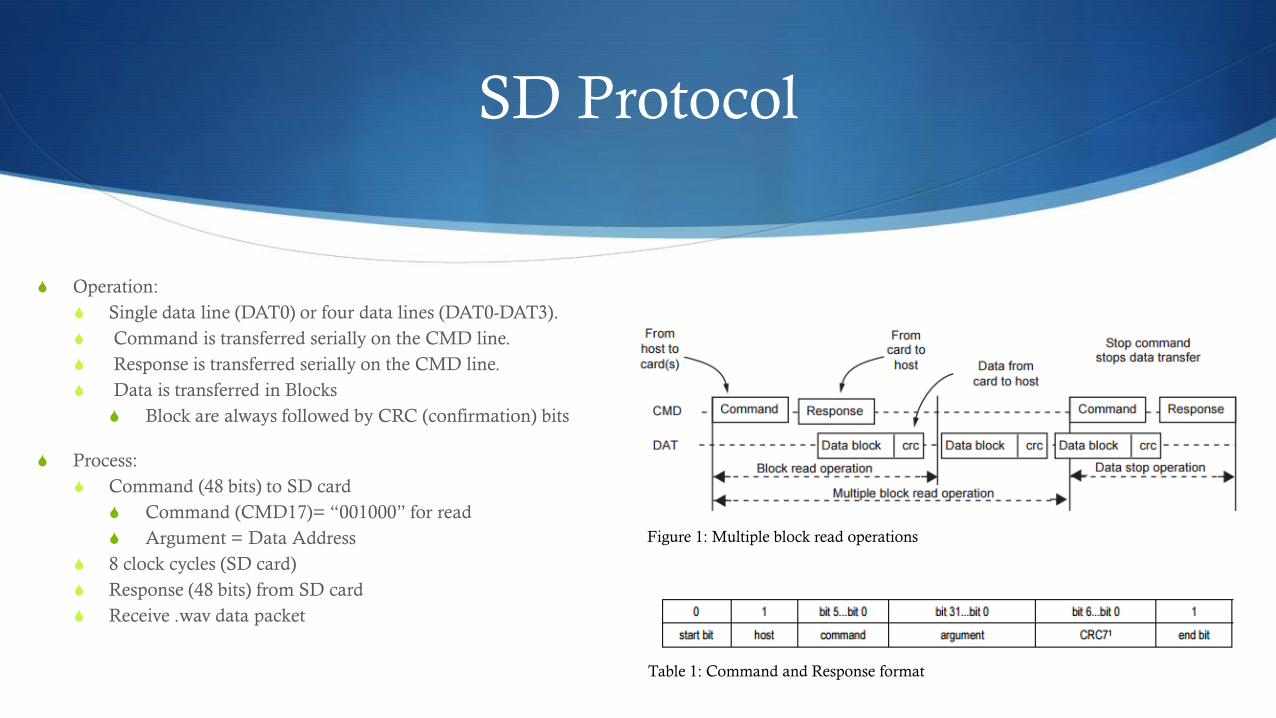
S Operation:
S Single data line (DAT0) or four data lines (DAT0-DAT3).
S Command is transferred serially on the CMD line.
S Response is transferred serially on the CMD line.
S Data is transferred in Blocks
S Block are always followed by CRC (confirmation) bits
S Process:
S Command (48 bits) to SD card
S Command (CMD17)= “001000” for read
S Argument = Data Address
S 8 clock cycles (SD card)
S Response (48 bits) from SD card
S Receive .wav data packet
Figure 1: Multiple block read operations
Table 1: Command and Response format
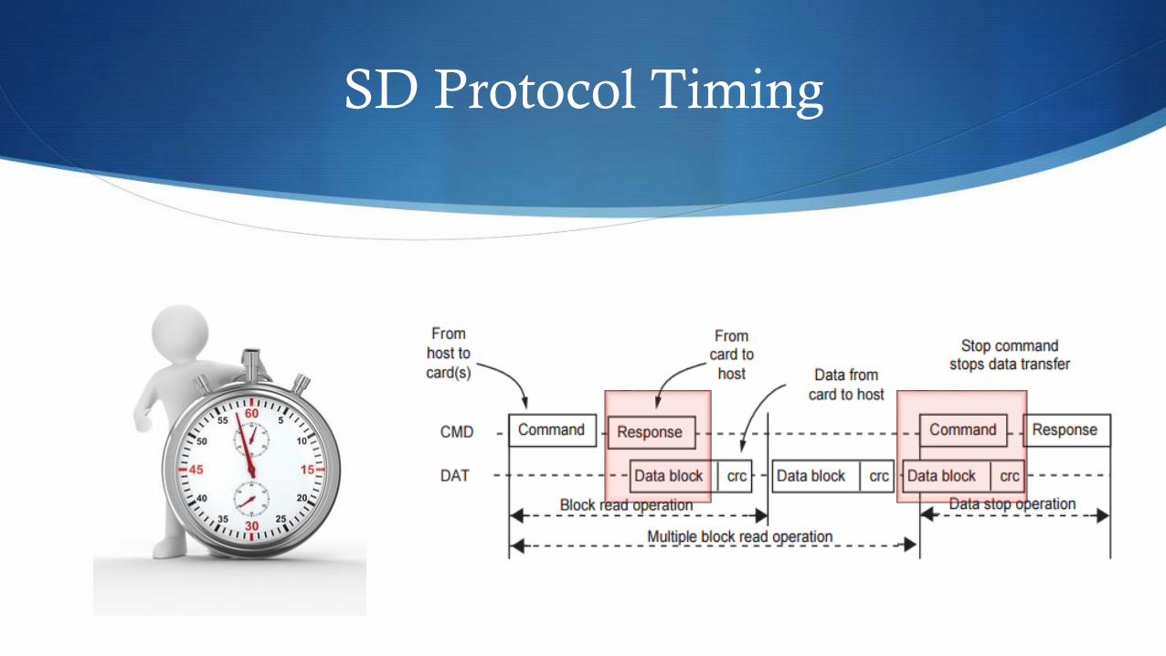
SD Protocol Timing

SPI Protocol
S Initialization
S DI and SD = 1
S Wait minimum 90 clock cycles
S CMD0 = 0x00000000
S Sent CMD1 to check status
S Response change from Idle to ready (0x01 0x00)
S Process
S Send command signal (48 bits)
S Wait 8 clock cycles for SD card to process
S SD card sends 48-bit response
S Command Response Time (NCR)
S 0 to 8 bytes
S SD card then sends data stream
Figure 1. Single block read operation
Figure 2. Timing of single block read operation

SD (Secure Digital Card) Uncertainties
S FAT32 SD card formatting
S Where exactly is the data located within
the SD card file directory?
S Timing of the .wav file message
S Was the entire length of the .wav file
being received?

SD Format
S File Allocation Table (FAT)
S Disk divided into clusters
S First 512 bytes is boot sector
S Cannot be changed
S Stores information about disk
S 4 to 64 sectors per cluster
S Clusters determine where a file is located
S FAT16
S Cards 128MB to 2GB
S FAT32
S Cards 2GB to 32GB
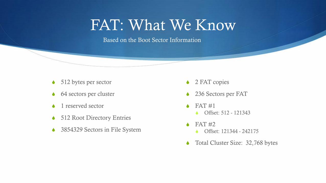
FAT: What We Know
S 512 bytes per sector
S 64 sectors per cluster
S 1 reserved sector
S 512 Root Directory Entries
S 3854329 Sectors in File System
S 2 FAT copies
S 236 Sectors per FAT
S FAT #1 S Offset: 512 - 121343
S FAT #2 S Offset: 121344 - 242175
S Total Cluster Size: 32,768 bytes
Based on the Boot Sector Information
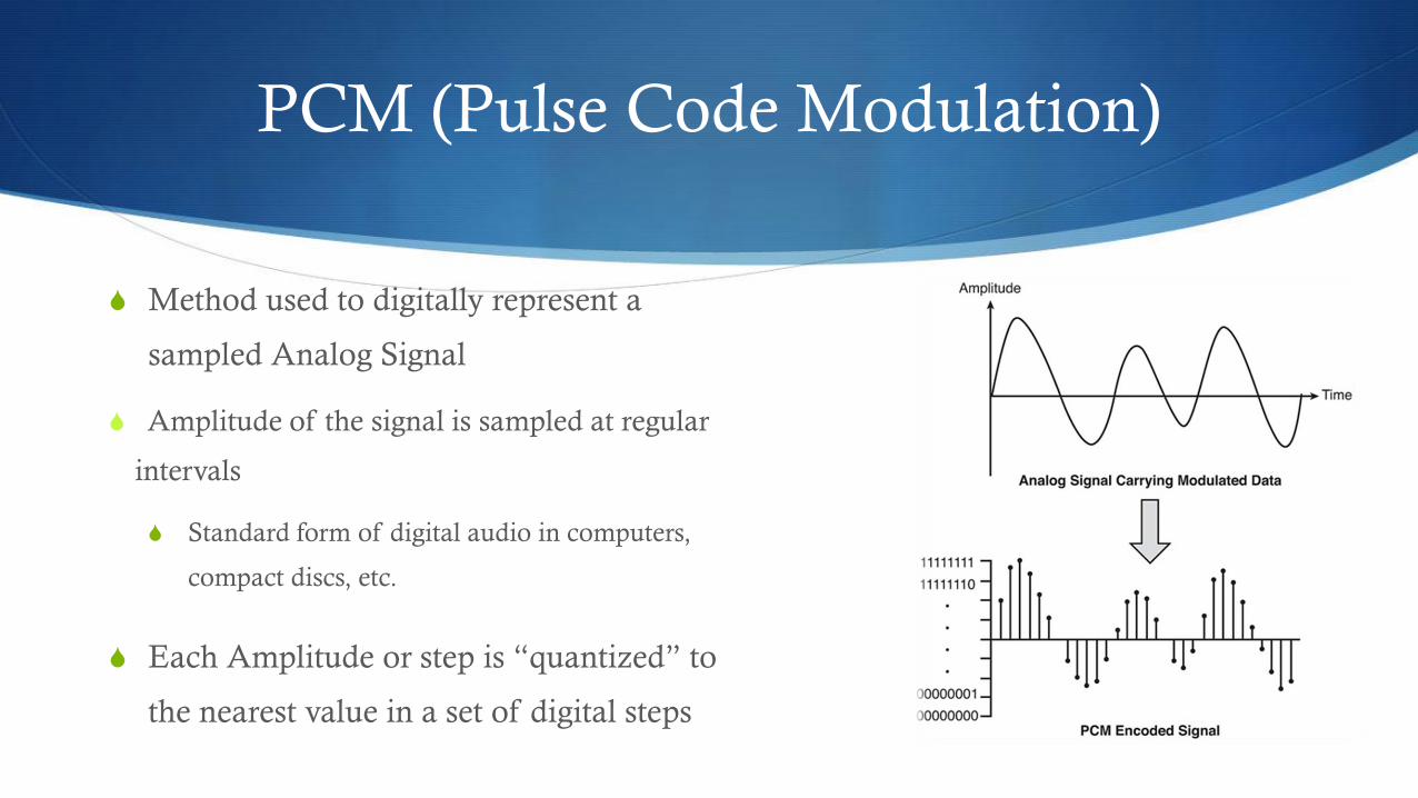
PCM (Pulse Code Modulation)
S Method used to digitally represent a
sampled Analog Signal
S Amplitude of the signal is sampled at regular
intervals
S Standard form of digital audio in computers,
compact discs, etc.
S Each Amplitude or step is “quantized” to
the nearest value in a set of digital steps
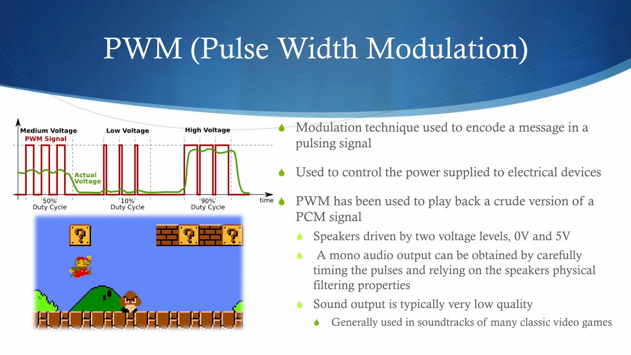
PWM (Pulse Width Modulation)
S Modulation technique used to encode a message in a
pulsing signal
S Used to control the power supplied to electrical devices
S PWM has been used to play back a crude version of a
PCM signal
S Speakers driven by two voltage levels, 0V and 5V
S A mono audio output can be obtained by carefully
timing the pulses and relying on the speakers physical
filtering properties
S Sound output is typically very low quality
S Generally used in soundtracks of many classic video games
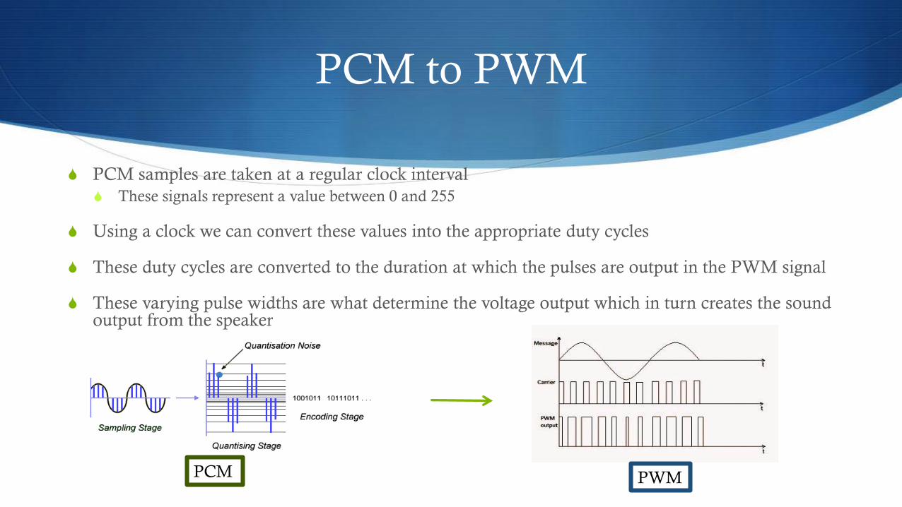
PCM to PWM
S PCM samples are taken at a regular clock interval
S These signals represent a value between 0 and 255
S Using a clock we can convert these values into the appropriate duty cycles
S These duty cycles are converted to the duration at which the pulses are output in the PWM signal
S These varying pulse widths are what determine the voltage output which in turn creates the sound output from the speaker
PCM PWM

Timer (Seven Segment Display)
S Interfaced to keep track of the total
time for which each sound plays
S Starts counting when the SD PCM
data transfers
S Uses the PCM output of the
Microprocessor unit to know when to
stop based on the output
S First 4 displays used for name of track
S Last 4 displays used for timer

Display FSM’s
7 Seg Displays Timer

Further Design Applications
S Interfacing the SD card with the
appropriate and understanding the overall
file structure will lead to many different
applications including:
S Loading multiple tracks
S Saving recorded tracks
S Looping multiple sounds
S Audio Amplification
Recommended