IPv6 Addressing IPv6 Transition Strategies and
Technologies Workshop 5th – 6th August 2014
Vientiane
1 Last updated 16 June 2014

Agenda p Recap: how it worked with IPv4 p Getting IPv6 address space p Constructing a scalable IPv6 address plan p IPv6 addressing on LANs p IPv6 address plan example
2

How it used to be Looking back at IPv4
3

How did it work for IPv4? p Up until 1994:
n Operators applied to InterNIC for address space p 1993 onwards: included RIPE NCC and APNIC
n Class A: Big organisations n Class B: Medium organisations
p From 1992 onwards, multiple class Cs often handed out instead of single class Bs
n Class C: Small organisations
p From 1994 onwards (classless Internet) n Address space distributed by InterNIC (replaced by ARIN
in 1998) and the other RIRs n Distribution according to demonstrated need (not
organisation size or want) 4

IPv4 address plans (pre 1994)? p Prior to 1994, doing an address plan in IPv4 was
very simple p Class C was used for one LAN
n If entity had more than one LAN, they’d normally get a class B
p An organisation with a class B had 256 possible LANs n And that was more than most networks had in those
days p Organisations with more than 256 LANs tended to
be Universities, big IT companies, etc n They either had multiple class Bs, or even a class A
5

Typical early 90s address plan p Organisation was not connected to the Internet
as such n But used TCP/IP internally
p Would generally use 10.0.0.0/8 n Or any other class A that InterNIC had not handed out
p 10.X.Y.Z was a typical layout, where: n X = building number n Y = LAN number n Z = host address n Where each subnet was a /24 (like a class C)
p When these organisations connected to the Internet, they had to renumber n Often into a /19 (the minimum allocation then) 6

IPv4 address plans (post 1994)? p In the classful Internet days, IP address planning
didn’t really exist n The address space was big enough for most needs, as
the number of devices and LANs were small p With the arrival of classless Internet, and IPv4
runout in the early 90s n IP address planning was needed n Organisations got address space according to
demonstrated need p A previous class B might now only get a /19 p LANs no longer were automatically /24s p etc
7

IPv4 address plans (post 1994)? p Advent of NAT assisted with delaying IPv4 runout
n End-user got single public address, and NATed on to that address
p (End-users could get lazy again)
p Operators became more careful: n RIR policy required “demonstrated need”
p Further allocations made only when existing allocations were proven to be mostly used up
n Started assigning address space across backbone according to the needs of the infrastucture
p No gaps, but still no real plan p /30s for point-to-point links etc p Although the “plans” often separated infrastructure address
space from what went to customers 8

IPv4 address plans (today) p Chaotic? p Unstructured? p Undocumented? p With IPv4 address space almost all depleted
n Operators becoming ever more creative n Operators extracting the last “drops” from their address
space holdings n It is a scramble just to keep network infrastructure
addressed with public IPv4 n Some operators even use NAT within their backbones n Some operators are reclaiming IPv4 address space
loaned to their customers n This hotch potch cannot and does not lead to good
planning 9

IPv4 address plans (today) p More serious issues – because of the lack of
structure, lack of planning: n Infrastructure security filters become very hard to
manage p Adding yet another small block of IPv4 addresses to
perimeter and control plane filters n Traffic engineering is more challenging
p Lots of small blocks of address space to manage and manipulate
p With impacts on size of the global routing table too! n Infrastructure addressing is difficult to manage
p Loopbacks and backbone point-to-point links no longer out of one contiguous block
n Access address pool resizing p Broadband access pools renumbering, reassigning, etc 10

IPv6 p IPv6 changes all this p Address space delegations are generous
n Reminders of the “old days” of classful IPv4
p No NAT p Address planning is very possible p Address planning is very necessary p Documentation is very necessary p Operators accustomed to handling IPv4 in the
1980s and early 1990s might be able to use those old skills for IPv6 !
11

IPv6 Address Planning
12

Where to get IPv6 addresses p Your upstream ISP p Africa
n AfriNIC – http://www.afrinic.net
p Asia and the Pacific n APNIC – http://www.apnic.net
p North America n ARIN – http://www.arin.net
p Latin America and the Caribbean n LACNIC – http://www.lacnic.net
p Europe and Middle East n RIPE NCC – http://www.ripe.net/info/ncc
13

Internet Registry Regions
14

Getting IPv6 address space (1) p From your Regional Internet Registry
n Become a member of your Regional Internet Registry and get your own allocation
p Membership usually open to all network operators
n General allocation policies are outlined in RFC2050
p RIR specific policy details for IPv6 allocations are listed on the individual RIR website
n Open to all organisations who are operating a network
n Receive a /32 (or larger if you will have more than 65k /48 assignments)
15

Getting IPv6 address space (2) p From your upstream ISP
n Receive a /48 from upstream ISP’s IPv6 address block
n Receive more than one /48 if you have more than 65k subnets
p If you need to multihome: n Apply for a /48 assignment from your RIR n Multihoming with provider’s /48 will be
operationally challenging p Provider policies, filters, etc
16

Using 6to4 for IPv6 address space p Some entities still use 6to4
n Not recommended due to operational problems n Read http://datatracker.ietf.org/doc/draft-ietf-
v6ops-6to4-to-historic for some of the reasoning why p FYI: 6to4 operation:
n Take a single public IPv4 /32 address n 2002:<ipv4 /32 address>::/48 becomes your IPv6
address block, giving 65k subnets n Requires a 6to4 gateway n 6to4 is a means of connecting IPv6 islands across the
IPv4 Internet
17

Nibble Boundaries p IPv6 offers network operators more flexibility
with addressing plans n Network addressing can now be done on nibble
boundaries p For ease of operation
n Rather than making maximum use of a very scarce resource
p With the resulting operational complexity
p A nibble boundary means subnetting address space based on the address numbering n Each number in IPv6 represents 4 bits = 1 nibble n Which means that IPv6 addressing can be done on 4-bit
boundaries 18

Nibble Boundaries – example p Consider the address block 2001:db8:0:10::/61
n The range of addresses in this block are:
n Note that this subnet only runs from 0010 to 0017. n The adjacent block is 2001:db8:0:18::/61
n The address blocks don’t use the entire nibble range
19
2001:0db8:0000:0010:0000:0000:0000:0000 to
2001:0db8:0000:0017:ffff:ffff:ffff:ffff
2001:0db8:0000:0018:0000:0000:0000:0000 to
2001:0db8:0000:001f:ffff:ffff:ffff:ffff

Nibble Boundaries – example p Now consider the address block
2001:db8:0:10::/60 n The range of addresses in this block are:
n Note that this subnet uses the entire nibble range, 0 to f n Which makes the numbering plan for IPv6 simpler
p This range can have a particular meaning within the ISP block (for example, infrastructure addressing for a particular PoP)
20
2001:0db8:0000:0010:0000:0000:0000:0000 to
2001:0db8:0000:001f:ffff:ffff:ffff:ffff

Addressing Plans – Infrastructure p All Network Operators should obtain a /32 from
their RIR p Address block for router loop-back interfaces
n Number all loopbacks out of one /64 n /128 per loopback
p Address block for infrastructure (backbone) n /48 allows 65k subnets n /48 per region (for the largest multi-national networks) n /48 for whole backbone (for the majority of networks) n Infrastructure/backbone usually does NOT require
regional/geographical addressing n Summarise between sites if it makes sense
21

Addressing Plans – Infrastructure p What about LANs?
n /64 per LAN
p What about Point-to-Point links? n Protocol design expectation is that /64 is used n /127 now recommended/standardised
p http://www.rfc-editor.org/rfc/rfc6164.txt p (reserve /64 for the link, but address it as a /127)
n Other options: p /126s are being used (mimics IPv4 /30) p /112s are being used
§ Leaves final 16 bits free for node IDs p Some discussion about /80s, /96s and /120s too
22

Addressing Plans – Infrastructure p NOC:
n ISP NOC is “trusted” network and usually considered part of infrastructure /48
p Contains management and monitoring systems p Hosts the network operations staff p take the last /60 (allows enough subnets)
p Critical Services: n Network Operator’s critical services are part of the
“trusted” network and should be considered part of the infrastructure /48
n For example, Anycast DNS, SMTP, POP3/IMAP, etc p Take the second /64 p (some operators use the first /64 instead)
23

Addressing Plans – ISP to Customer p Option One:
n Use ipv6 unnumbered n Which means no global unicast ipv6 address on the point-
to-point link n Router adopts the specified interface’s IPv6 address
p Router doesn’t actually need a global unicast IPv6 address to forward packets
interface loopback 0 ipv6 address 2001:db8::1/128 interface serial 1/0
ipv6 address unnumbered loopback 0
24

Addressing Plans – ISP to Customer p Option Two:
n Use the second /48 for point-to-point links n Divide this /48 up between PoPs n Example:
p For 10 PoPs, dividing into 16, gives /52 per PoP p Each /52 gives 4096 point-to-point links p Adjust to suit!
n Useful if ISP monitors point-to-point link state for customers
p Link addresses are untrusted, so do not want them in the first /48 used for the backbone &c
n Aggregate per router or per PoP and carry in iBGP (not ISIS/OSPF)
25

Addressing Plans – Customer p Customers get one /48
n Unless they have more than 65k subnets in which case they get a second /48 (and so on)
p In typical deployments today: n Several ISPs are giving small customers a /56 and single
LAN end-sites a /64, e.g.: /64 if end-site will only ever be a LAN /56 for small end-sites (e.g. home/office/small business) /48 for large end-sites
n This is another very active discussion area n Observations:
p Don’t assume that a mobile endsite needs only a /64 p Some operators are distributing /60s to their smallest customers!!
26
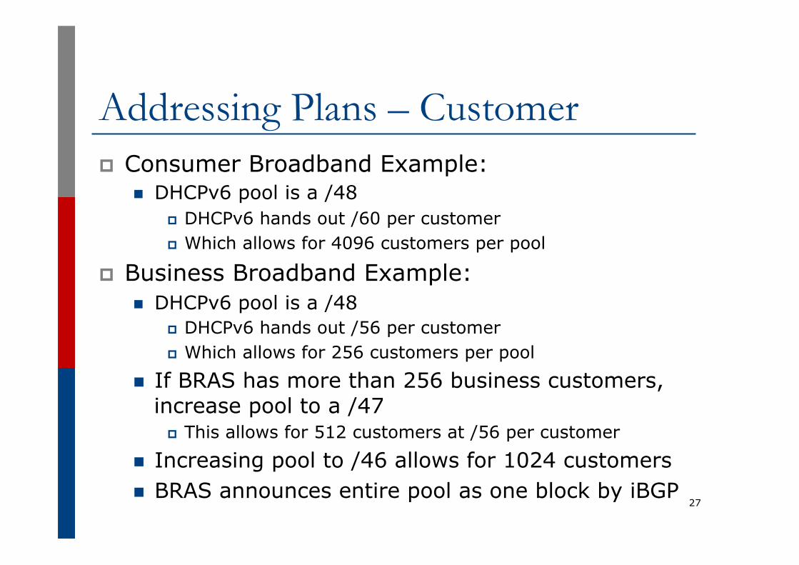
Addressing Plans – Customer p Consumer Broadband Example:
n DHCPv6 pool is a /48 p DHCPv6 hands out /60 per customer p Which allows for 4096 customers per pool
p Business Broadband Example: n DHCPv6 pool is a /48
p DHCPv6 hands out /56 per customer p Which allows for 256 customers per pool
n If BRAS has more than 256 business customers, increase pool to a /47
p This allows for 512 customers at /56 per customer
n Increasing pool to /46 allows for 1024 customers n BRAS announces entire pool as one block by iBGP
27

Addressing Plans – Customer p Business “leased line”:
n /48 per customer n One stop shop, no need for customer to revisit ISP for
more addresses until all 65k subnets are used up p Hosted services:
n One physical server per vLAN n One /64 per vLAN n How many vLANs per PoP? n /48 reserved for entire hosted servers across backbone
p Internal sites will be subnets and carried by iBGP
28
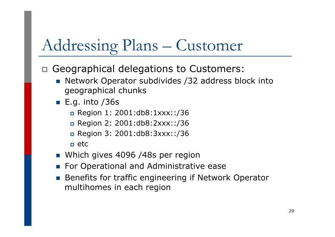
Addressing Plans – Customer p Geographical delegations to Customers:
n Network Operator subdivides /32 address block into geographical chunks
n E.g. into /36s p Region 1: 2001:db8:1xxx::/36 p Region 2: 2001:db8:2xxx::/36 p Region 3: 2001:db8:3xxx::/36 p etc
n Which gives 4096 /48s per region n For Operational and Administrative ease n Benefits for traffic engineering if Network Operator
multihomes in each region
29

Addressing Plans – Customer p Sequential delegations to Customers:
n After carving off address space for network infrastructure, Network Operator simply assigns address space sequentially
n Eg: p Infrastructure: 2001:db8:0::/48 p Customer P2P: 2001:db8:1::/48 p Customer 1: 2001:db8:2::/48 p Customer 2: 2001:db8:3::/48 p etc
n Useful when there is no regional subdivision of network and no regional multihoming needs
30
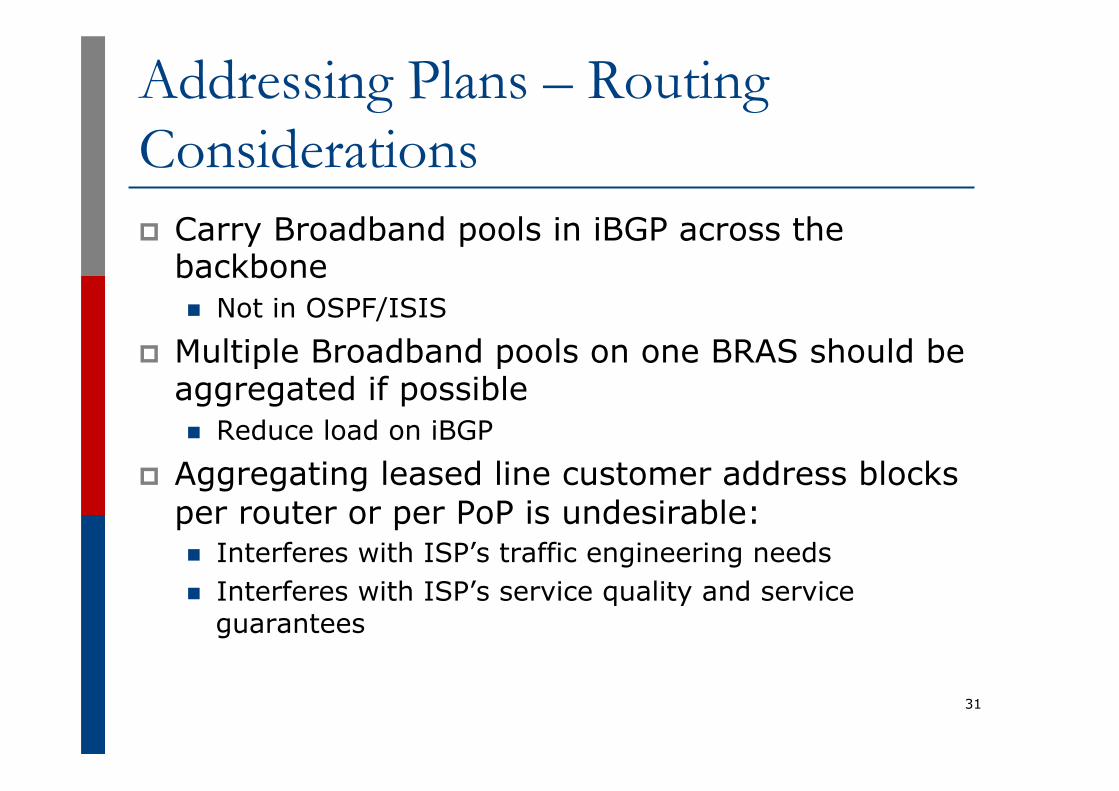
Addressing Plans – Routing Considerations p Carry Broadband pools in iBGP across the
backbone n Not in OSPF/ISIS
p Multiple Broadband pools on one BRAS should be aggregated if possible n Reduce load on iBGP
p Aggregating leased line customer address blocks per router or per PoP is undesirable: n Interferes with ISP’s traffic engineering needs n Interferes with ISP’s service quality and service
guarantees
31

Addressing Plans – Traffic Engineering p Smaller providers will be single homed
n The customer portion of the ISP’s IPv6 address block will usually be assigned sequentially
p Larger providers will be multihomed n Two, three or more external links from
different providers n Traffic engineering becomes important n Sequential assignments of customer addresses
will negatively impact load balancing
32

Addressing Plans – Traffic Engineering p ISP Router loopbacks and backbone point-to-
point links make up a small part of total address space n And they don’t attract traffic, unlike customer address
space p Links from ISP Aggregation edge to customer
router needs one /64 n Small requirements compared with total address space n Some ISPs use IPv6 unnumbered
p Planning customer assignments is a very important part of multihoming n Traffic engineering involves subdividing aggregate into
pieces until load balancing works 33

Unplanned IP addressing p ISP fills up customer IP addressing from one end
of the range:
p Customers generate traffic n Dividing the range into two pieces will result in one /33
with all the customers and the ISP infrastructure the addresses, and one /33 with nothing
n No loadbalancing as all traffic will come in the first /33 n Means further subdivision of the first /33 = harder work
34
2001:db8::/32
Customer Addresses ISP
1 2 3 4 5

Planned IP addressing p If ISP fills up customer addressing from both
ends of the range:
p Scheme then is: n First customer from first /33, second customer from
second /33, third from first /33, etc p This works also for residential versus commercial
customers: n Residential from first /33 n Commercial from second /33
35
2001:db8::/32
Customer Addresses ISP
1 3 5 7 9 2 4 6 8 10
Customer Addresses

Planned IP Addressing p This works fine for multihoming between two
upstream links (same or different providers) p Can also subdivide address space to suit more
than two upstreams n Follow a similar scheme for populating each portion of
the address space p Consider regional (geographical) distribution of
customer delegated address space p Don’t forget to always announce an aggregate
out of each link
36

Addressing Plans – Advice p Customer address assignments should not be
reserved or assigned on a per PoP basis n Follow same principle as for IPv4 n Subnet aggregate to cater for multihoming needs n Consider regional delegation n ISP iBGP carries customer nets n Aggregation within the iBGP not required and usually not
desirable n Aggregation in eBGP is very necessary
p Backbone infrastructure assignments: n Number out of a single /48
p Operational simplicity and security n Aggregate to minimise size of the IGP
37
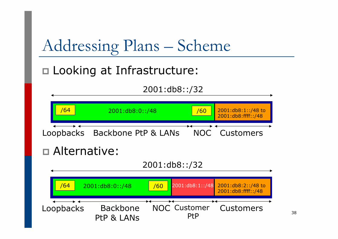
Addressing Plans – Scheme p Looking at Infrastructure:
38
2001:db8::/32
Customers Backbone PtP & LANs Loopbacks
/64 2001:db8:0::/48 /60
NOC
2001:db8:1::/48 to 2001:db8:ffff::/48
2001:db8::/32
Customers Backbone PtP & LANs
Loopbacks
/64 2001:db8:0::/48 /60
NOC Customer PtP
2001:db8:1::/48 2001:db8:2::/48 to 2001:db8:ffff::/48
p Alternative:

Addressing Plans Planning p Registries will usually allocate the next
block to be contiguous with the first allocation n (RIRs use a sparse allocation strategy –
industry goal is aggregation) n Minimum allocation is /32 n Very likely that subsequent allocation will
make this up to a /31 or larger (/28) n So plan accordingly
39
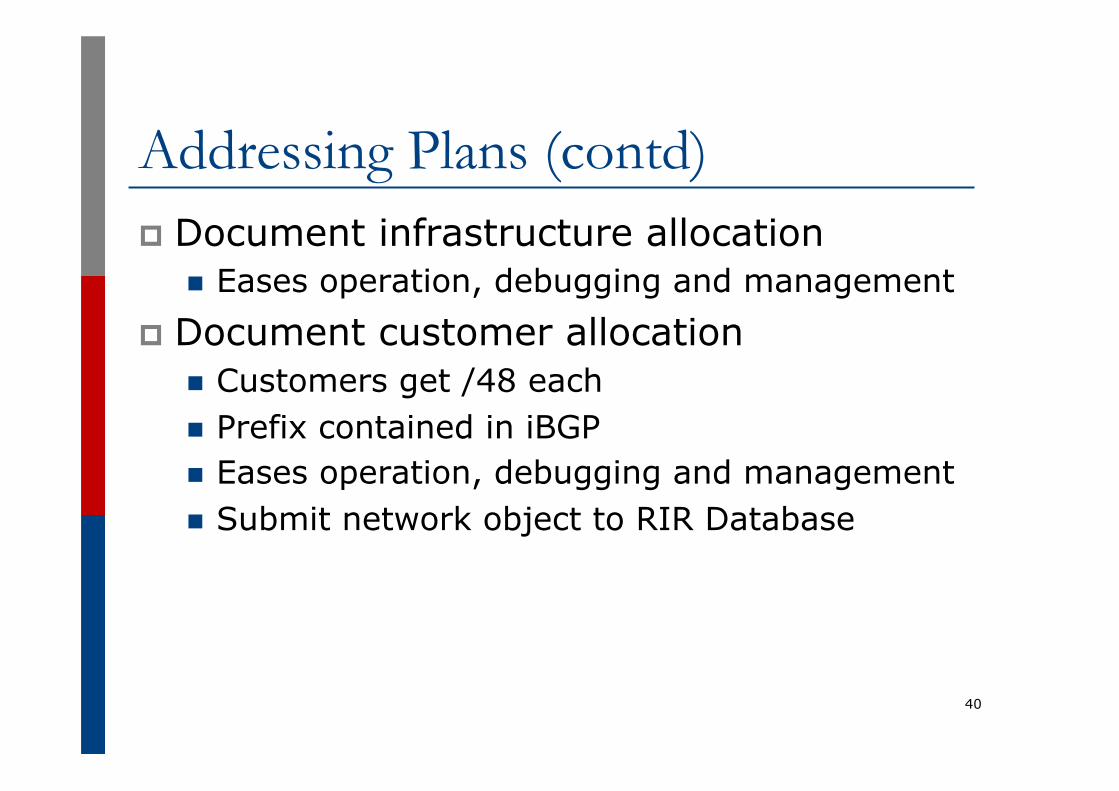
Addressing Plans (contd) p Document infrastructure allocation
n Eases operation, debugging and management p Document customer allocation
n Customers get /48 each n Prefix contained in iBGP n Eases operation, debugging and management n Submit network object to RIR Database
40

Addressing Tools p Examples of IP address planning tools:
n NetDot netdot.uoregon.edu (recommended!!) n HaCi sourceforge.net/projects/haci n Racktables racktables.org n IPAT nethead.de/index.php/ipat n freeipdb home.globalcrossing.net/~freeipdb/
p Examples of IPv6 subnet calculators: n ipv6gen code.google.com/p/ipv6gen/ n sipcalc www.routemeister.net/projects/sipcalc/
41

IPv6 Addressing on LANs
42

IPv6 Addressing on LANs p Two options:
n Stateless Autoconfiguration (SLAAC) p Client learns IPv6 address from the router on the
subnet n DHCPv6
p Client learns IPv6 address from a DHCP server (as for IPv4)
43

SLAAC p IPv6 client learns address “from the LAN”
n Sends out “router solicit” n Router responds with “router advertisement”
containing subnet and default gateway n Initial client state:
n Router does not need any specific configuration
44
Client: en3: flags=8863<UP,BROADCAST,SMART,RUNNING,SIMPLEX,MULTICAST> mtu 1500
ether 68:5b:35:7d:3b:bd inet6 fe80::6a5b:35ff:fe7d:3bbd%en3 prefixlen 64 scopeid 0x8
interface FastEthernet0/0 ipv6 address 2001:db8::1/64 ipv6 nd router-preference high !

SLAAC p On receiving response from the router:
n Note the temporary address – this is the one used for all IPv6 connectivity, and has a lifetime determined by the client’s operating system
45
en3: flags=8863<UP,BROADCAST,SMART,RUNNING,SIMPLEX,MULTICAST> mtu 1500 ether 68:5b:35:7d:3b:bd inet6 fe80::6a5b:35ff:fe7d:3bbd%en3 prefixlen 64 scopeid 0x8 inet6 2001:db8:100::6a5b:35ff:fe7d:3bbd prefixlen 64 autoconf inet6 2001:db8:100::18eb:2861:458e:862b prefixlen 64 autoconf temporary nd6 options=1<PERFORMNUD>
Internet6: Destination Gateway Flags Netif Expire default fe80::219:30ff:fee UGc en3

DHCPv6 p Works like DHCP on IPv4 infrastructure:
n DHCPv6 server distributes addresses from a pool on request from client
n DHCPv6 client configures IPv6 address n Sample server configuration (Cisco IOS):
46
ipv6 dhcp pool LABNET dns-server 2001:DB8:1::1 dns-server 2001:DB8:2::2 domain-name labnet ! interface VLAN1 ipv6 address 2001:DB8::1/64 ipv6 dhcp server LABNET !

Distributing subnets by DHCP p Two options:
n Static assignment (as in IPv4) p Tell the customer what subnet they have
n DHCPv6-PD p Use DHCPv6 Prefix Delegation feature to distribute
subnets automatically
47
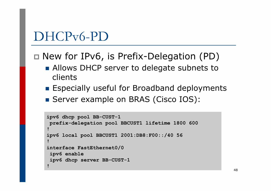
DHCPv6-PD p New for IPv6, is Prefix-Delegation (PD)
n Allows DHCP server to delegate subnets to clients
n Especially useful for Broadband deployments n Server example on BRAS (Cisco IOS):
48
ipv6 dhcp pool BB-CUST-1 prefix-delegation pool BBCUST1 lifetime 1800 600 ! ipv6 local pool BBCUST1 2001:DB8:F00::/40 56 ! interface FastEthernet0/0 ipv6 enable ipv6 dhcp server BB-CUST-1 !

DHCPv6-PD p Client receives address delegation from
the server:
49
interface Dialer0 description ADSL link to MY ISP ipv6 address autoconfig default ipv6 dhcp client pd ADSL-PD rapid-commit ! interface Vlan1 description Home Network ipv6 address ADSL-PD ::1/64 ! interface Vlan2 description Home IP/TV Network ipv6 address ADSL-PD ::1:0:0:0:1/64 !
Vlan1 – IPv6 address: 2001:DB8:F00:3100::1/64 Vlan2 – IPv6 address: 2001:DB8:F00:3101::1/64
Example Address Plan
50

Example Address Plan p Generic Network Operator
n Has 2001:db8::/32 address block n Takes first /48 for network infrastructure
p First /64 for loopbacks p Last /60 for NOC
n Takes second /48 for point to point links to customer sites
n Remainder of address space for delegation to customers, content hosting and broadband pools
p Network Operator has 20 PoPs around the country 51

Example: Loopback addresses p 2001:db8:0::/48 is used for infrastructure p Out of this, 2001:db8:0:0::/64 is used for
loopbacks n Each loopback is numbered as a /128
p Scheme adopted is: n 2001:db8::XXYY/128
p Where XX is the PoP number (01 through FF) p Where YY is the router number (01 through FF)
n Scheme is good for: p 255 PoPs p 255 routers per PoP p keeping addresses small/short
52
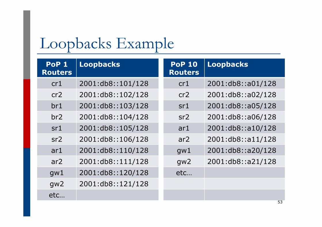
Loopbacks Example PoP 1
Routers Loopbacks
cr1 2001:db8::101/128 cr2 2001:db8::102/128 br1 2001:db8::103/128 br2 2001:db8::104/128 sr1 2001:db8::105/128 sr2 2001:db8::106/128 ar1 2001:db8::110/128 ar2 2001:db8::111/128 gw1 2001:db8::120/128 gw2 2001:db8::121/128 etc…
PoP 10 Routers
Loopbacks
cr1 2001:db8::a01/128 cr2 2001:db8::a02/128 sr1 2001:db8::a05/128 sr2 2001:db8::a06/128 ar1 2001:db8::a10/128 ar2 2001:db8::a11/128 gw1 2001:db8::a20/128 gw2 2001:db8::a21/128 etc…
53

Example: Backbone Point to Point links p Backbone Point to Point links come out of
Infrastructure block 2001:db8:0::/48 n Scheme adopted is:
p 2001:db8:0:MNXY::Z/64
n Where p MN is the PoP number (01 through FF) p XY is the LAN number (00 through 0F) p XY is the P2P link number (10 through FF) p Z is the interface address (0 or 1)
n Scheme is good for 16 LANs and 240 backbone PtP links per PoP, and for 255 PoPs
54

LANs and PtP Links Example PoP 1 Subnet LAN1 2001:db8:0:101::/64 LAN2 2001:db8:0:102::/64 LAN3 2001:db8:0:103::/64 PtP1 2001:db8:0:111::/64 PtP2 2001:db8:0:112::/64 PtP3 2001:db8:0:113::/64 PtP4 2001:db8:0:114::/64 PtP5 2001:db8:0:115::/64 PtP6 2001:db8:0:116::/64 PtP7 2001:db8:0:117::/64 etc…
PoP 14 Subnet LAN1 2001:db8:0:e01::/64 LAN2 2001:db8:0:e02::/64 LAN3 2001:db8:0:e03::/64 LAN4 2001:db8:0:e04::/64 LAN5 2001:db8:0:e05::/64 PtP1 2001:db8:0:e11::/64 PtP2 2001:db8:0:e12::/64 PtP3 2001:db8:0:e13::/64 etc…
55 Note: PtP links have /64 reserved but are addressed as /127s

Links to Customers p Some ISPs use “ip unnumbered” for IPv4
interface links n So replicate this in IPv6 by using “ipv6
unnumbered” to address the links n This will not require one /48 to be taken from
the ISP’s /32 allocation p Other ISPs use real routable addresses
n So set aside the second /48 for this purpose n Gives 65536 possible customer links, assuming
a /64 for each link
56
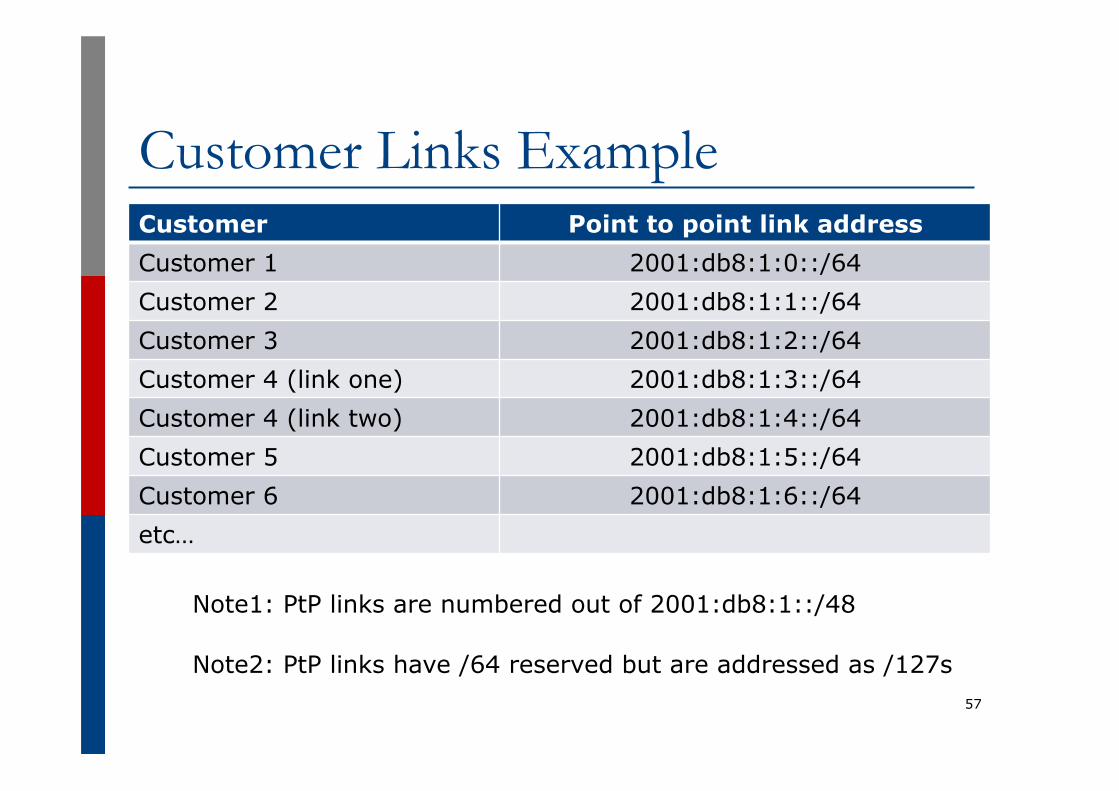
Customer Links Example Customer Point to point link address Customer 1 2001:db8:1:0::/64 Customer 2 2001:db8:1:1::/64 Customer 3 2001:db8:1:2::/64 Customer 4 (link one) 2001:db8:1:3::/64 Customer 4 (link two) 2001:db8:1:4::/64 Customer 5 2001:db8:1:5::/64 Customer 6 2001:db8:1:6::/64 etc…
57
Note1: PtP links are numbered out of 2001:db8:1::/48
Note2: PtP links have /64 reserved but are addressed as /127s

Example: Allocations from the /32 p Master allocation documentation would look like
this:
58
Category Purpose
Single /64 Loopbacks
Single /60 NOC
Single /48 Backbone Point to Point links (/64 each)
Single /48 Customer Point to Point links (/64 each)
Single /40 65536 Broadband Customers in Region 1 (/56 each)
Single /40 256 Enterprise Customers in Region 1 (/48 each)
Single /40 65536 Broadband Customers in Region 2 (/56 each)
Single /40 256 Enterprise Customers in Region 2 (/48 each)
Etc…

Example: Allocations from the /32 p Detailed documentation:
59
Address Blocks Purpose
2001:db8:0::/48 Infrastructure (Loops, NOC, PtP)
2001:db8:1::/48 Customer Point to Point Links
2001:db8:0110::/48 Customer One in Region 1
2001:db8:0111::/48 Customer Two in Region 1
2001:db8:0112::/48 Customer Three in Region 1
2001:db8:1100::/40 Broadband Pool 1 in Region 1
2001:db8:1200::/40 Broadband Pool 2 in Region 1
2001:db8:8110::/48 Customer One in Region 2
2001:db8:8111::/48 Customer Two in Region 2
2001:db8:9100::/40 Broadband Pool 1 in Region 2
2001:db8:9200::/40 Broadband Pool 2 in Region 2
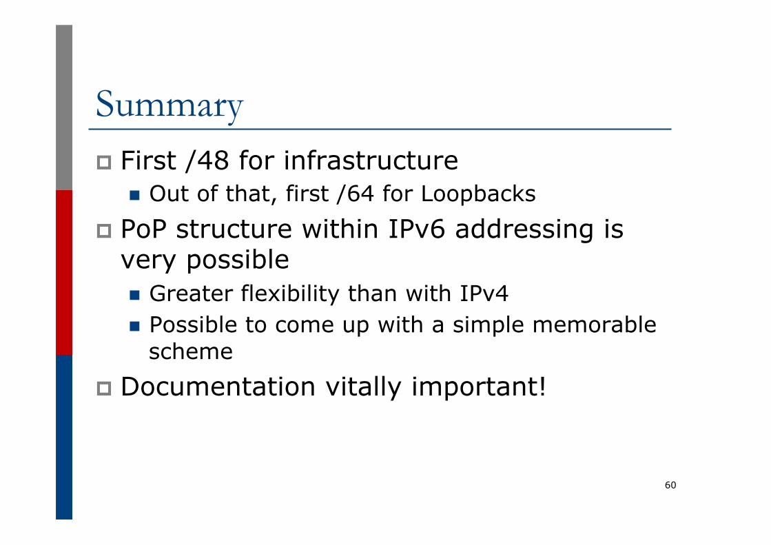
Summary p First /48 for infrastructure
n Out of that, first /64 for Loopbacks p PoP structure within IPv6 addressing is
very possible n Greater flexibility than with IPv4 n Possible to come up with a simple memorable
scheme p Documentation vitally important!
60

Presentation Recap p How it worked with IPv4 p Getting IPv6 address space p Constructing a scalable IPv6 address plan p IPv6 addressing on LANs p IPv6 address plan example
61

IPv6 Addressing IPv6 Transition Strategies and
Technologies Workshop 5th – 6th August 2014
Vientiane
62
Recommended