3V0
TS 75TS 100
English
Installation Instructions for garage door operators
This booklet must be handed over to the end-user together with the user-manual.
and

2 3
Content
Information and Remarks
Directives and RegulationsUse of the operatorsGarage DoorsThe installer’s declaration of conformityOlder Garage Doors
Important Information for the Installer 3Instruction for the users
Security Advises for the Installation 4
Installation
Different Conditions for Installation 5Minimum space above the garage doorDoor Arm ExtensionC-Rail ExtensionBow Arm Conversion
Pre-Mounting the operator 6
Installing the operator 7
The Emergency Release 8When there is a second entrance to the garageWhen the garage door is the only entrance
Printed Circuit Board: Adjustments and Connections
Devices for Adjustments 9TEST/RUN-Button (1)LERN/LEARN-Button (2)Potentiometer “PRESSURE OPEN/CLOSE“ (3)Potentiometer “LIGHT“ (4)
Limit-Switch Adjustment and Force Measurement 10Information1.) Adjusting the maximum force for the learning-cycle2.) Starting the learning-mode3.) The Limit Switch Adjustment4.) Starting the Learning-CycleQuick Reference
Enhanced Adjustments 12The BOTTOM Soft-StopThe length of the BOTTOM Soft-Stop may be changed during the first run of the learning-cycle in closing direction:Programming the BOTTOM Soft-ModeTop Soft ModeEnabling the Top Soft ModeReducing the Closing SpeedWhy reduce the Closing Speed?When to reduce the Closing Speed?Programming the Closing Speed
The most important connectors 14
Advanced Connectors 14Push Button and Key Switch 24V DC Supply230V AC SupplyReceiver-ModulePhoto-Cell without selftest:Photo-Cell with selftestSafety Beam, Hatch Door, Emergency StopModules for Special FunctionsCycle Counter
LED-Lamps 16LED “TEST“LED “Diag“LED “Vp“LED „LSZ“LED „SLZ“LED “SEZ“LED “SEA“
Special Functions 17DIP-Switch SettingsFunction 1: TOP Soft-ModeFunction 2:Automatic Force MeasurementForce Setting TS75 or TS100Pre-Warning light before every movementFull reversion in OPENING directionNo reversion on Security-Beam when door closed Side Hinged Doors
Remote Control
Programming the Hand Transmitters 18BasicsProgramming Transmitter and ReceiverClearing the receivers‘ memory
Additional Information 19Criterias influencing the rangeUse with a HomeLink© System
Technical Information
Technical Data 20
Optional Special Functions 20Module “Automatic Closing“ (AZ)Module “Separated Impulse“ (TO)Module “One Way Traffic Control“ (EI)Maintenance:
Wiring 21Internal WiringExternal connections
Spare Parts 22
Troubleshooting
Troubleshooting 23Error MessagesError messages via the operator‘s lightIf... then...Additional messages only via the LED “Diag“
Declaration of Conformity

2 3
It is within legal regulation and without restriction, to use a Seip door operator with any garage door that has been ap-proved for use with other certified door operators!
Directives and RegulationsThe operators TS 75 and TS 100 comply to the latest European di-rectives and regulations. The declaration of conformity is enclosed at the end of these instructions.
Use of the operatorsThe operators were designed for the use with up-and-over doors (tilting and canopy-type) and sectional doors. They can be used with side-hinged doors using a special conversion-kit.All garage doors need to be maintained before automation. The door must be easily opened and closed by hand. A garage door must not be automated unless it is easy to open and close manu-ally.
Garage DoorsIn January 2001 the European regulations EN12604 and EN12605 became compulsory for garage doors. Before installing an au-tomatic door operator it must be assured that the garage doors applies to these regulations (the information can be obtained from the manufacturers‘ declaration of conformity). A Seip door opera-tor may be installed to any door that complies with the regula-tions. Should a garage door not be compliant then please refer to the chapter „older garage doors“.
The installer’s declaration of conformityNo matter whether a door operator was delivered together with a garage door or separately, the installer must issue a declaration of conformity for the complete installation.With this declaration the installer assures, that the installation was made according to the instructions given by the manufactur-ers (e.g. the installation instructions of the garage door and the operator). This declaration can only be issued by the installer and may not be issued from the manufacturer!If both components comply with the directives and the installation was made as to the manufacturers instructions the whole installa-tion will normally be CE-compliant.
Older Garage DoorsWhen automating an older garage-door the TS-series will still comply with the regulations - through the automatic force setting the requested values for forces and reversion will be according to the regulations.But it needs to be taken in consideration that most older garage doors do not meet the regulations EN 12604 and EN 12605 - especially regarding security features. They might still have sharp edges bearing the danger of severe injuries - for example sectional doors might not have a finger protection between the sections. Unfortunately the entire regulations do not mention how to handle the automation of such an older garage door - the danger basically is not the automation but the construction of the door.
Therefore we strongly recommend to- Check the garage door for sharp edges bearing danger when the door is moving; take any necessary action to avoid the dan-gers and make the door safer- Check the doors‘ springs and readjust them if necessary- Grease or oil the pivotal points and rollers of the garage door- Check that the door may be easily used by hand
If, however, the dangers cannot be avoided we recommend using the automatic pre-warning function of the operator. The operator’s light will then blink for approx. 5 sec. before every movement of the garage door. People inside the garage will be alerted before the garage opens and can step back from the door in time.
Instruction for the usersPlease instruct the users as follows:- Use of the hand transmitter- Use of the emergency release in case of a power failure- Hand over the separate „User Manual“ to the customer- Inform the user about the Security Advises in the User Manual
Important Information for the Installer
Information and Remarks

4 5
Security Advises for the Installation
Information and Remarks
Important Safety Instructions for InstallationWARNING: INCORRECT INSTALLATION CAN LEAD TO SEVERE INJURYFollow all Installation Instructions.
- Read page 3 of these instruction carefully before the installation
- Before installing the drive, remove unnecessary ropes from the existing installation
- Maintain the garage door according to the advice on page 3 and to the door manufacturer’s manual
- If possible, install the drive at a height of at least 2,10 m and the manual release at a height less than 1,80 m
- Locate the push-button within sight of the door but away from moving parts and at a minimum height of 1,50 m
- Fix the warning label at eye level to garage door
- The label fixed to the manual release must not be removed
- After installation, ensure that the mechanism is properly adjusted and that the drive reverses when the door contacts a 40 mm high object placed on the floor.
4 5
Different Conditions for Installation
Installation
35mm Minimum
Minimum space above the garage door
C-Rail Extension
Bow Arm Conversion
Door Arm Extension
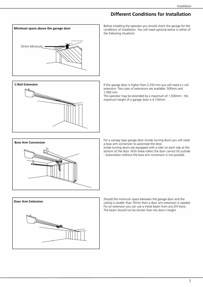
Before installing the operator you should check the garage for the conditions of installation. You will need optional extras in either of the following situations:
If the garage door is higher than 2.250 mm you will need a c-rail extension. Two sizes of extensions are available: 500mm and 1.000 mm.The operator may be extended by a maximum of 1.500mm - the maximum height of a garage door is 4.150mm.
For a canopy type garage door (inside turning door) you will need a bow arm conversion to automate the door.Inside turning doors are equipped with a roler on each side at the bottom of the door. With these rollers the door cannot tilt outside - Automation without the bow arm conversion is not possible.
Should the minimum space between the garage door and the ceiling is smaller than 35mm then a door arm extension is needed. For an extension you can use a metal beam from any DIY-store. The beam should not be shorter than the door‘s height.

(1)
(1)
(2)(3)
(3)
(4)
6 7
During this procedure be careful not to twist the chain. Therefore do not lift the parts - slide them along the floor.
1. The operator is lying unpacked in front of you. The motor-head unit is on your right hand side.
2. Lay part (1) to the front.
3. Fix through pushing the C-profile coupling piece (2) over it all the way home.
4. Slide C-rail part (3) in front of part (1)
5. Set part (3) in the C-rail coupling piece (4) at an angle, inserting it from above as shown.
6. Press down part (3) to tension the chain.
7. Turn around the operator and screw in the milled nuts into the C-rail coupling pieces.
Your operator is now ready for installation.
The chain has been pretensioned in the factory; do not change the chain tension!
ATTENTION:The setting of the limit-switches and the automatic-force adjustment were set for factory testings. When you change the limit-switch settings you first have to run a new learn-ing cycle to make the operator work properly! (Please refer to the pages 10+11)
Pre-Mounting the operator
Installation

(1)
(2)
(2a)
(3)
(3a)
(4)
(5)
(6)
6 7
Installing the operator
Installation
Measure the distance between the ceiling and the highest point reached by the garage door (1).The minimum-headroom necessary for mounting the operator is 35 mm. If there is less headroom please pay attention to page 5.
The front fixing angle can be mounted either at the lintel or at the ceiling.
1. Measure the middle of your garage door and make a mark on the lintel and the top of your door (2+2a).
2. Fix the front fixing angle in the middle either at the lintel or at the ceiling. (We recommend the lintel if possible) (2+2a).
3. Attach the C-rail to the front fixing angle (3). Put a carton piece under the motor head unit to avoid damages.
4. To fix the motor head to the ceiling we recommend you to use a ladder (4). When the operator is lying on the ladder you can open the garage-door. Adjust the C-rail according to the mark you made in the middle of the garage-door.Fix the operator to the ceiling when you have made sure the C-rail is running straight to the front.
5. Now fix the door arm to the garage door (5). Take care that the angle between the operator and the door arm does not exceed a max. of 45° (it may be lower).
6. Before running the operator disengage the door‘s lock-ing-bolts otherwise the operator cannot open the door. This could result in damage to the operator and/or the garage door. The self-locking gear of the operator will ensure that the door cannot be opened manually. If you require additional secu-rity, ie using door bolts, please ask your dealer for our locking set, which is available as an optional extra.

8 9
Installation
In case of a power failure the garage door can be opened by hand. Therefore the operator first needs to be released.
When the garage door is the only entranceIt is necessary to connect the emergency release to the door‘s handle (Pic. 1) otherwise the garage cannot be accessed during power failure situation.
Proceed as follows:
1. Find out in which direction the door handle moves when open-ing the door.
2. Drill a hole in the side of the door handle that turns down-wards.
3. Thread the cable through the hole and fix it with the enclosed metal-clamps. Be careful not to put a high tension on the emer-gency release cable - the operator then might release from the garage-door during a normal opening cycle.
4. Check the function of the emergency release together with a second person. Stay inside the garage and close the door with the operator. Let the second person open the door manually with the door keys. If this works, the emergency-release is mounted properly.
Do not leave the garage and close the garage-door with the operator before you have tested the emergency-release!
The Emergency Release
When there is a second entrance to the garageYou can use the supplied handle for the emergency release (Pic. 2).Thread the emergency release cable through the handle. Fix the metal clamps to the cable where the handle shall be placed.Shorten the cable below the metal clamps - the handle is now be-ing held by the clamps.
In case of a power failure the user can now open the garage door by releasing the operator with the handle for the emergency acess.
Pic. 1
Pic. 2

12
34
8 9
Devices for Adjustments
Printed Circuit Board: Adjustments and Connections
TEST/RUN-Button (1)With this button you put the operator into operation. The button works on the OPEN-STOP-CLOSE principle, e.g. the first push opens the door, the second push stops the door and the third push closes the door etc.The LED-lamp “TEST“ is switched on as long as you press the TEST-button and shows that the impulse was received an recog-nised by the electronics.
LERN/LEARN-Button (2)This button has to functions:
1. Learning the forces2. Registering (learning) a hand-transmitter
The LERN/LEARN-button must be pressed for approx. 3 sec.; the button can be released once the operator‘s light starts blinking. Whilst the operator‘s light is blinking you can either register a new hand-transmitter by pushing the hand transmitters button O R you may start the learning of forces by pressing the button once again.Details on both procedures can be obtained from the chapters “Automatic Force Setting“ and “Remote Control“.
Potentiometer “PRESSURE OPEN/CLOSE“ (3)With these potentiometers you must adjust the maximum force for the force learning cycle (please refer to the chapter “Automat-ic Force Setting“) separately for OPENING and CLOSING direction. The operator will never override the adjusted forces, neither dur-ing the learning cycle nor in later use!The maximum forces are shown in %. Dependant on the operator model this means:
max.force
%age
Operator with 75 kg max.
Operator with
100 kg max.
20% 15 kg approx. 20 kg approx.
50% 37 kg approx. 50 kg approx.
70% 52 kg approx. 70 kg approx.
100% 75 kg 100 kg
Potentiometer “LIGHT“ (4)With this potentiometer the time for the internal lighting is ad-justed in seconds. Timing from 80 to 240 seconds are available.
This page only shows the functions of the buttons and potentiometers on the P.C.B. To programme the operator please refer to page 10 onwards.

12
3
10 11
Limit-Switch Adjustment and Force Measurement
InformationTo use the operator the following steps must be carried out, to adjust the limit-switches and to learn the required force. Without these adjust-ments the operator will only run for the factory set distance when pressing the TEST-button.
The limit-switch adjustment and the force-learning are both done in one combined programming step. The operator needs to be set into program-ming-mode - the programming-mode is indicated by the blinking opera-tor’s light. During the programming-mode the limit-switch setting is done first, followed by the force-setting.
The procedure of adjustments:1.) Adjustment of the maximum force for learning-mode2.) Start of programming-mode3.) OPENING limit-switch b.) Adjustment CLOSING limit-switch4.) Start the learning-cycle for force and distance.
Descriptions of each step will be found in the following text.
1.) Adjusting the maximum force for the learning-cycleThe force adjusted via the potentiometers “FORCE OPEN“ and “FORCE CLOSE“ determines the maximum forces for the learning cycle and in later use. The factory setting is 60% for both. On smaller, easy running doors a force of 40% will be sufficient.
Printed Circuit Board: Adjustments and Connections
2.) Starting the learning-modePress the LERN/LEARN button (2) on the main electronics for approx. 3 sec-onds. When the operator’s light begins blinking - release the LERN/LEARN button.The operator now runs in learning-mode. The learning-mode runs without time-limit - there is no need to rush with the following adjustments.
3.) The Limit Switch AdjustmentIn CLOSING-position the garage door should not be forced hard onto the doors‘ frame. If it is closed to firmly then the operator will reverse after each CLOSING and the garage door will remain open for approx. 5 cm.
Basics: During the learning-mode the operator will follow the limit-switch-es automatically when these are moved.E.g.: The operator hits the CLOSING limit-switch but the garage-door still is not completely closed. You can now slide the red limit-switch actuator off the CLOSING limit-switch - the operator will automatically start running in CLOSING direction until it hits the CLOSING limit-switch again. You do not have to press the TEST/RUN button to activate the operator.The procedure works vice-versa in OPENING direction.
Attention: the operator only follows the limit-switch in ONE direction - the CLOSING limit-switch is only followed in CLOSING direction, the OPENING limit-switch is only followed in OPENING direction.To run the operator in another direction you have to press the TEST/RUN button.
IMPORTANT INFORMATION PRIOR TO PROGRAMMING!
The programming described on this and the following page will programme the operator with factory pre-set values for Soft-Modes and Closing Speed.
Dependant on the type and the weight of the garage door it might be necessary to reduce the Closing Speed. On page 13 you will find a weight table and a description on how to programme the Closing Speed.
If the Soft-Modes require readjustment, please refer to page 12.
To change the standard values it is allways necessary to run another complete learning cycle - the old values will then be substituted by the new measurements and adjustments.Old values can allways be overwritten by starting and completing a new learning cycle.
Pictures:1: TEST/RUN-Button2: LERN/LEARN-But-ton3: Potentiometer for Force Adjustment

�������� ����������
�������� ����������
10 11
Limit-Switch Adjustment and Force Measurement
Printed Circuit Board: Adjustments and Connections
Quick Reference
1.) Force Adjustment Adjust the maximum force for OPENING and CLOSING direction for the learning cycle
2.) Start programming mode
Press the LERN/LEARN button for approx. 3 seconds. The operator’s light begins blinking - release the LERN/LEARN button
3.) Limit Switch Adjustment a.) Adjust OPENING limit switchb.) Adjust CLOSING limit switch(The operator can be run in OPENING and CLOSING direction using the TEST/RUN button)
4.) Start learning cycle The garage door is closed and the operators hits the CLOSING limit switchPress the LERN/LEARN button shortlyThe operator does three runs (OPENING-CLOSING-OPENING)
The learning cycle stops after the three runs. The garage door is then opened and the operator’s light stops blinking. The pro-gramming is now complete.
5.) You may now proceed with chapter “Remote Control“ on page 16
The operator’s light will be blinking throughout the whole procedure of setting the limit switch.
3.)a.) Adjusting the OPENING limit switch1.) Run the operator in OPENING direction using the TEST/RUN button (1) (the button follows the principle OPEN-STOP-CLOSE etc., e.g. first impulse OPEN, second impulse STOP, third impulse CLOSE etc.)2.) When the garage door is almost opened to maximum you have to stop the operator using the TEST/RUN button. Then slide the OPENING limit switch actuator so that it hits the limit-switch.3.) When the OPENING limit switch is hit before the garage door is opened to maximum then simply slide the red limit switch actuator further in OPENING direction - the operator will follow the movement.
3.)a.) Adjusting the CLOSING limit-switch1.) Run the operator in CLOSING direction using the TEST/RUN button (1) (the button follows the principle OPEN-STOP-CLOSE etc., e.g. first impulse OPEN, second impulse STOP, third impulse CLOSE etc.)2.) When the garage door is closed you have to stop the operator using the TEST/RUN button. Then slide the OPENING limit switch actuator so that it hits the limit switch.3.) When the CLOSING limit switch is hit before the garage door is closed then simply slide the red limit switch actuator further in CLOSING direction - the operator will follow the movement.
4.) Starting the Learning-CycleOnce the limit-switches are adjusted, press the LERN/LEARNbutton once again. The operator then starts the learning cycle:
- moving towards the limit-switch OPEN- closing the door- opening the door- closing the door The learning-cycle will be made completely automatic - you only have to intervene, when the CLOSING Soft-Stop shall either be changed or disab-led (please refer to the information box on page 10).Once the learning-cycle is completed, the operator stops blinking; the garage is in closed position.After the learning-cycle the operator is completely programmed - please proceede to the chapter „Remote-Control“.

�������� ����������
123456
LERN/LEARNTEST/RUN
123456
LERN/LEARNTEST/RUN
�������� ����������
12 13
Quick Reference „Programming the BOTTOM Soft-Mode“
1.) First learning cycle in CLOSING direction
Keep the LERN/LEARN button pressed during the first run in CLOSING direction and keep it pressed -the operator increases speed
2.) The operator is running in CLOSING direction with increased speed
Release the LERN/LEARN button at the position where the soft-stop shall start in future.If the LEARN button is kept pressed until the door is com-pletely shut, then the soft-stop will be disabled.
3.) The operator reaches the CLOSED position. It will proceed with the learning-cycle (two more runs) before finishing the pro-gramming. The CLOSING Soft-Stop will then be set as to your adjustments.
The BOTTOM Soft-StopThe length of the BOTTOM Soft-Stop may be changed during the first run of the learning-cycle in closing direction:
- Extending the BOTTOM Soft-Stop is recommended, if the garage door slams on closing.
- Reducing or disabling the BOTTOM Soft-Stop is recommen-ded, when the bottom of the garage door does not close completely. Expecially when mechanical spring-locks are installed, these might not engage. When the BOTTOM Soft-Stop is disabled, the garage door reaches the closing position with a higher speed. This gives the door a higher momentum and the bottom can fall into the doors‘ frame - the locks can then engage.
Programming the BOTTOM Soft-ModeThe length of the soft-stop can be adjusted during the first au-tomatic measurement-run in closing direction. Please proceed as described below:
1. Start the learning cycle (refer to page 11)2. the operator runs in closing direction with low speed3. press the LERN/LEARN button and keep it pressed - the opera-tor is now increasing the speed4. release the LERN/LEARN button at the position where the soft-stop shall begin (the operator will store this position as the beginning of the BOTTOM soft-stop)If the Soft-Stop is to be disabled, then the LEARN button must be pressed until the door is completely closed.5. the operator will reduce speed with a short delay and then reach the closing position6. the operator will proceede with the remaining measurement-runs
When the operators‘ light stops blinking, all measured values are saved in the memory - the BOTTOM soft-stop now is in the programmed position.
Top Soft ModeUsing the standard programming will disable the Top Soft Mode. For up-and-over doors and sectional doors this standard setting will not require any changes.On canopy doors the Top Soft Mode might need to be enabled, when the operator constantly reverses after starting to close the garage door.
Enabling the Top Soft ModeBefore starting the learning cycle, DIP-switch no. 1 must be set to OFF. The switch must remain in OFF position during the complete learning cycle. Once it is finished (e.g. the operators light stops blinking), DIP-switch no. 1 must be set to ON position again, otherwise the operator will not work on automatic force (please refer to page 17 „DIP-switch settings“).
Hint: although the Top Soft Mode is now disabled, the operator will not instantly start running with full speed when closing the door. To prevent excessive wear to the motor gear, the speed will be increased continuosely from zero to maximum speed.
Quick Reference „Enabling the Top Soft Mode“
1.) Set DIP-Switch No. 1 to OFF before starting the learning cycle
2.) Start the learning cycle
(if necessary the closing soft stop can now be ammended as mentioned in the previous chapter)
3.) Set DIP-Switch No. 1 to ON after the learning cycle is completed
(please refer to page 17 „DIP-Switch Settings“)
Bottom Soft-Stop
Top Soft Mode
Enhanced Adjustments
Printed Circuit Board: Adjustments and Connections

LERN/LEARNTEST/RUN
LERN/LEARNTEST/RUN
TEST Diag Vp
TEST/RUN LERN/LEARN
LERN/LEARNTEST/RUN
�
�
�
�
�
�
�
�
� � �� �� � �� �� � �� �� ���� ��� ����
�
�
�
�
�
12 13
Enhanced Adjustments
Reducing the Closing SpeedWhen using the standard programming procedure, then the clo-sing speed is automatically set to maximum; for most CE compliant garage doors no changes are necessary.
Why reduce the Closing Speed?Reducing the closing speed will also reduce the forces and the time for reversion which appear when the garage door hits an obstacle.The greater the weight of a garage door, the higher the mass that needs to be moved, stopped and reversed in case of detection of an obstacle. Especially on heavy doors this momentum may result in a short peak force, leading to higher forces on the leading edge . The lower the closing speed, the lower the momentum of force and the peak forces.
When to reduce the Closing Speed?The table besides provides information on suggested closing speeds for different door weights. For new, CE-compliant doors you should find the doors weight either labelled on the door or in the instructions. Adjust the closing speed according to this infor-mation, as far as a change is required.When automating an older, non CE-compliant garage door, we strongly recommend to use speed level 4 or lower (please also refer to page 3).
Programming the Closing SpeedThe programming of the closing speed must be made before running the learning cycle. If, however, the learning cycle was already completed, it must be run again after changing the closing speed.
1.) The operator is switched on2.) Press the red LEARN-button and keep it pressed. Press the black TEST-button in addition and keep both buttons pressed for approx. 3 seconds.3.) The operators light starts blinking and the red LED „Diag“ blinks in intervalls; the buttons can now be released.4.) The LED „Diag“ is blinking in intervalls (8 blinks followed by a short break) - indicating the factory pre-set speed level 8.5.) Each press of the TEST-button will reduce the closing speed by one level, each press of the LEARN-button will increase the speed.After readjusting the speed, wait for the short break between the intervalls and count the number of blinks from there to check the entirely adjusted speed level.6.) Once you reached the wanted closing speed level, press the LEARN-button and in addition the TEST-button and keep both pressed for approx. 1 second.7.) The closing speed is now adjusted and the operator is now in the ordinary learning mode (the operators light and the LED „Diag“ are blinking constantly). If the limit-switches were adjusted already, you can now start the learning cycle by shortly pressing the red LEARN-button.Otherwise you can now adjust the limit-switches (please refer to pages 10 and 11) and then start the learning cycle.
Quick Reference „Ajusting the Closing Speed“
1.) First press LEARN button, then in addition TEST-button, keep both pressed for 3 sec.
The operators light begins blinking when the buttons are pressed
2.) Red LED „Diag“ begins to blink in intervalls
Release both buttons when the LED „Diag“ starts blinking
Factory pre-set: 8 blinks followed by a short break (= max. speed)
3.) Reduction of speed by pressing the TEST button
Each press on the TEST button reduces the closing speed by one level (pressing the LERN button will increase the speed).
Wait for the break and count the number of blinks from there to check the entire adjustment.
4.) First press LEARN button, then in addition TEST-button and release both
The operator is now in the ordinary learning mode; the operators light and the LED „Diag“ are now blin-king simultaneousely.
5.) Adjust the limit-switches and start the learning-cycle.If changes to the soft modes are necessary, then please refer to page 12.
If the limit-switches had been adjusted previousely, the learning-cycle can be started instantly by shortly pressing the LERN button.
Speed Level (No. of blinks of the LED „Diag“)
Closing Speed (cm/sec.)
1 6 cm/sec.
2 6,5 cm/sec.
3 7,5 cm/sec.
4 9,5 cm/sec.
5 10,5 cm/sec.
6 11,5 cm/sec.
7 12,5 cm/sec.
8 14,5 cm/sec.
Speed Level
Door Weight in kg
Printed Circuit Board: Adjustments and Connections
��
�� �
�� � �� �
�� �
������� �W
��
�� �
�� � �� �
�� �
������� �W
�
�
14 15
The most important connectors
Printed Circuit Board: Adjustments and Connections
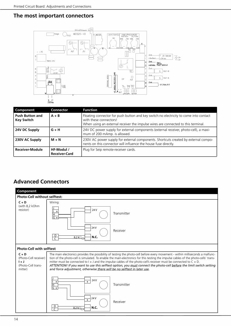
Component Connector Function
Push Button and Key Switch
A + B Floating connector for push button and key switch:no electricity to come into contact with these connectors!When using an external receiver the impulse wires are connected to this terminal.
24V DC Supply G + H 24V DC power supply for external components (external receiver, photo-cell), a maxi-mum of 200 mAmp. is allowed.
230V AC Supply M + N 230V AC power supply for external components. Shortcuts created by external compo-nents on this connector will influence the house fuse directly.
Receiver-Module HF-Modul / Receiver-Card
Plug for Seip remote-receiver cards.
Advanced Connectors
Component
Photo-Cell without selftest:
C + D(with 8,2 kOhm resistor)
Wiring:
Photo-Cell with selftest
C + D(Photo-Cell receiver)I + J(Photo-Cell trans-mitter)
The main electronics provides the possibility of testing the photo-cell before every movement - within milliseconds a malfunc-tion of the photo-cell is simulated. To enable the main-electronics for this testing the impulse cables of the photo-cells‘ trans-mitter must be connected to I + J and the impulse cables of the photo-cell’s receiver must be connected to C + D.ATTENTION! If you want to use this selftest option, you must connect the photo-cell before the limit switch setting and force adjustment, otherwise there will be no selftest in later use.
Transmitter
Receiver
Transmitter
Receiver

��
��� �W
��
��� �W
��
��� �W
Gnd
Gnd
14 15
Advanced Connectors
Printed Circuit Board: Adjustments and Connections
Safety Beam, Hatch Door, Emergency Stop
E + F(mit 8,2 kOhm Auswertung)
Function This connector is continuosely checked during opening and closing procedures. When the contact is opened (e.g. an obstacle is detected), then the operators stops and reverses shortly. If more than one component is connected to this connector, then they must be connected serial! The connector may be used for the following componentes:
1.) Safety-BeamThis device is normally equipped with a 8.2 kOhm resistor. Therefore you have to remove the 8.2 kOhm resistor from the con-nectors E + F before connecting the security-beam.2.) Hatch-Door SwitchA hatch-door within the garage door can be secured with a switch - when the switch is not activated (e.g. the hatch-door stands open) the operator will not work.3.) Emergency Stop - button which locks in when pressed once and which keeps the contact open (e.g. operator cannot be used)
Security Beam (8,2 kOhm resistor connected in line):
Hatch-Door Switch (8,2 kOhm resistor connected in line):
Security Beam and Hatch-Door (connected in line):
Modules for Special Functions
„Versions Mod-ule“
Plug for optional modules providing special functions:- Automatic Closing (AZ)- One-Way traffic control (EI) with traffic-light regulation- Dead-Man-Function (TO) (push-button needs to be pressed during the whole CLOSING cycle, otherwise the operator stops)
Cycle Counter
L A counter for OPENING/CLOSING cycles can be connected (24V)

16 17
LED-Lamps
Printed Circuit Board: Adjustments and Connections
LED Function ON OFF
LED “TEST“ “ON“ when a device connected to A+B (push-button, key-switch) or the electronics‘ TEST-button gives an impulse
Incoming impulse No incoming im-pulse
LED “Diag“ “ON“ when an impulse from a programmed hand-transmitter is received.More functions of this LED are named in the chapters “Learning the force“, “Remote-Control“ and “Error messages“.
Incoming impulse from a programmed hand-transmitter
No incoming im-pulse from a hand-transmitter
LED “Vp“ “ON“ when mains power supply is o.k. Mains power supply o.k.
No mains power
LED „LSZ“ Photo-CellPossible Errors:- an obstacle is registered by the photo-cell- the connection wires might be broken or a short-cut was created- the photo cell is damaged- the 8.2 kOhm resistor is not connected properly
Error or obstacle o.k.
LED „SLZ“ Security Contact / Hatch-Door SwitchPossible Errors:- the security beam registers an obstacle- the hatch-door is open- the connection wires might be broken or a short-cut was created- Security beam or hatch-door switch is damaged- the 8.2 kOhm resistor is not connected properly
Error or obstacle o.k.
LED “SEZ“ Checks the function of the CLOSING limit switch - when the limit switch is activated, the LED goes on. If it does not, then the limit switch is damaged.
activated not activated
LED “SEA“ Checks the function of the OPENING limit switch - when the limit switch is activated, the LED goes on. If it does not, then the limit switch is damaged.
activated not activated
DIP1 2 3 4 5 6
16 17
Printed Circuit Board: Adjustments and Connections
Special Functions
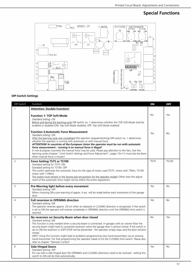
DIP-Switch Settings
DIP-Switch Function ON OFF
1 Attention: Double-Function!
Function 1: TOP Soft-ModeStandard setting: ONBefore and during the learning-cycle DIP-switch no. 1 determines whether the TOP Soft-Mode shall be enabled or disabled (ON: Top Soft-Mode disabled, OFF: Top Soft-Mode enabled)
Function 2:Automatic Force MeasurementStandard setting: ONAfter the learning cycle was completed (the operator stopped blinking) DIP-switch no. 1 determines whether the operator is running with automatic or with manual forceATTENTION! In countries of the European Union the operator must be run with automatic force measurement - running it on manual force is illegal!In non-European countries the manual force may be used. Please pay attention to the fact, that the learning cycles (chapter “Limit-Switch Settings and Force Adjustment“, pages 10+11) must also be done when manual force is chosen!
No
Yes
Yes
No
2 Force Setting TS75 or TS100Standard setting for TS75: ONStandard setting for TS100: OFFThis switch optimizes the automatic force for the type of motor used (TS75: motor with 75Nm, TS100: motor with 110Nm).The switch must remain in the factory pre-set position for the operator model! Other wise the adjust-ment of the automatic force might not be within the entire regulations.
TS75 TS100
3 Pre-Warning light before every movementStandard setting: OFFWhen choosing ON a pre-warning of appox. 4 sec. will be made before each movement of the garage door.
Yes No
4 Full reversion in OPENING directionStandard setting: ONThe operator reverses approx. 20 cm when an obstacle in CLOSING direction is recognised. If the switch is set to ON the operator will reverse completely in OPENING direction until the OPENING limit switch is reached.
Yes No
5 No reversion on Security-Beam when door closed Standard setting: ONThis function is only needed when a security-beam is connected. In garages with an uneven floor the security-beam might lead to unwanted reversion when the garage door is almost closed. If the switch is set to ON the revertion in SOFT-STOP will be prevented - the operator simply stops and the door remains closed.HINT! Using this function might lead to problems programming new hand-transmitters via an existing hand-transmitter. For that programming the operator needs to hit the CLOSING limit-switch. Please also refer to chapter “Remote Control“
No Yes
6 Side Hinged DoorsStandard setting: OFFFor use with a side hinged door the OPENING and CLOSING directions need to be reversed - setting this switch to ON will do that automatically.
Yes No

�������� ����������
18 19
Remote Control
Programming the Hand Transmitters
BasicsAs standard the operator is supplied with a 433 MHz AM re-mote control set. The coding is done via rolling code - the code is changed after each impulse; receiver and transmitter agree com-pletely automatic about the next code to be used. New codes will be chosen out of a pool of billions of possible codes.
The 4-channel MIDI transmitter is standard equipment, the 2-channel MINI transmitter is available as an optional extra.
If your operator is equipped with another remote control set, please refer to the manufacturers instructions for programming.
Programming Transmitter and ReceiverTo use a hand transmitter it must first be registered (programmed) by the receiver. Only one hand transmitter button can be used for one receiver.
Registering the first hand transmitterThe first hand transmitter (e.g. no hand transmitter has been registered for the receiver, yet) must be learned directly via the operators‘ main electronic:
1. Press the LERN/LEARN button on the main electronic for approx. 3 seconds until the operator’s light starts blinking and release the LERN/LEARN button.
2. Press the hand transmitter button you want to register to the receiver - the operators’ light stops blinking when the transmit-ters’ signal was received. The transmitter is now registered.
Registering additional hand transmittersWhen the receiver has registered at least one hand transmitter, you may program additional hand transmitters from a distance:
1. The garage door must be closed
2. Open the garage door for at least 50 cm and close it again.
3. After the garage door is closed you have got 10 seconds to press the buttons 1+2 simultaneously on the registered hand transmitter - the operator’s light then starts blinking.
4. The light will keep blinking for another 10 seconds - during that period of time you must press the button on the new hand transmitter that you want to use with the operator. Once the new transmitter is registered the operator’s light stops blinking.
The procedure must be repeated for each new hand transmitter.
Clearing the receivers‘ memoryKeep the LERN/LEARN button pressed for approx. 15 sec.. The operators‘ light and the red LED „Diag“ will start blinking after 3 seconds. After another 10 seconds the red LED „DIAG“ will glow constantly. You can then release the LERN/LEARN button. All previously programmed hand transmitters are now clea-red from the receivers‘ memory.
Quick reference: programming the first hand transmitter
1.) Keep the LERN/LEARN button pressed for approx. 3 sec.
The operators‘ light will start blinking
2.) Press the hand transmit-ter button you want to use
The operators‘ light stops blinking - the transmitter was succesfully programmed
Quick reference: Programming additional hand transmit-ters from a distance
Remark: additional hand transmitters can be programmed either like the first transmitter or from a distance as explained below:
1.) Open the garage door for at least 50 cm and close it again
After the garage door is closed you have got 10 seconds to pro-ceed to step 2)
2.) Press buttons 1+2 simultaneously on any registered transmitter for 3 sec.
The operators‘ begins blinking - release the hand transmitters‘ buttons
3.) Take the new hand transmitter and press the button you want to use shortly
The operators‘ light stops blinking - the hand transmitter was successfully programmed

1 2
3
4
18 19
Remote Control
4-channel MIDI transmitter, 433 MHz, rolling code
2-channel MINI transmitter (optional extra), 433 MHz, rolling code
Battery
Usable types of batteries: A23, 23A, 23L, EL12, VR 22 and MN 21Voltage: 12VUsed batteries must be disposed according to national laws!
Two batteries, type CR1616 or DL1616 are required. Voltage: 2* 3V (=6V)Used batteries must be disposed according to national laws!
Two Batteries
Criterias influencing the range
The TS operators are equipped with a high quality remote control set as a standard!
Nevertheless the remote control is the part of the operator, which might be influenced by circumstances in the surroundings of the garage. With our standard remote control you might reach a range of more than 100 meters. In areas with high disturbances the range will still be approx. 50 meters.
The range might be influenced by:
- old batteries in the hand transmitter - if you should experience a problem with the range, please change the batteries first. The lower the batteries run the lower the range will be.
- Building materials of the garageIn a garage made of concrete and steel you might reach a lower range than in an ordinary garage build of stone. The more steel was used for the walls the shorter the range of your remote-con-trol.
Remote-control activity in the areaRadio and television transmitters close to your garage might reduce the range.
Older baby-phonesEspecially older baby-phones might influence the range of the remote control severely. These devices send strong signals via the houses internal power supply net. These signals also intrude other devices via the wall plug, as eg the operator.
It is extremely unlikely that the range will drop to an unacceptable distance. If, however, problems should occur we will like to be helpful.
Please avoid dropping the hand transmitter - parts could be damaged inside the transmitter. That might lead to malfunctions!
Additional Information
Use with a HomeLink© System
The standard remote control SKR433-1 supplied with the TS-series is compatible with HomeLink© systems Software Revision 6 or higher. Older Software Revisions are not supported. Information on the Software Revision in your car and programming information can be obtained from the cars documentations (programming information is also available on the internet: www.eurohomelink.com).Programming procedure:1. Original hand-transmitter must be programmed into the HomeLink© Modul2. Garage Door Operator must be put into learning mode (page 18 “Programming additional hand transmitters from a distance”)3. A signal must be sent from the HomeLink© Module to the operator

20 21
TS 75 TS 100
Maximum Pulling Force (adjustable) 70 kg (+/- 4%) 100 kg (+/- 4%)
Force-Setting for Operation automatic automatic
Motor 24V DC, low-noise 24 V DC, low-noise
Running Speed 14,5 cm/sec. 14,5 cm/sec.
Speed in Soft Mode 8 cm/sec. 8 cm/sec.
Lighting 230V AC, max. 40 watts 230V AC, max. 40 watts
Lighting Durance (adjustable) 80 to 240 seconds 80 to 240 seconds
Duty Cycle 80% 80%
Power Consumption in Stand By 2,3 watts 2,3 watts
Power Supply 190-250V AC 190-250V AC
Transformer 230V AC, 24V DC 230V AC, 24V DC
Pre-Warning Light adjustable adjustable
Stop on Security Beam in Closing Direction adjustable adjustable
Automation of Side Hinged Doors adjustable adjustable
Nett Running Length 2.640 mm 2.640 mm
Max. Running Length with Extension 4.150 mm 4.150 mm
Overall Length 3.215 mm 3.215 mm
Height Motor Head 170 mm 170 mm
Length Motor Head 370 mm 370 mm
Width Motor Head 260 mm 260 mm
Minimum Space above the door 35 mm 35 mm
Weight including packaging 22 kg
Noise Level ≤ 60 dB(A) ≤ 60 dB(A)
Technical Data
For the TS-series operators we provide plug-on module cards for advanced functions:
Module “Automatic Closing“ (AZ)For automatic closing of the garage after an adjustable time from 80 to 240 seconds.The card is also equipped with a connector giving an impulse for one second when the garage door is opened - an automatic external light can be connected here.Special functions as “fast closing“ (the garage door will be closed as soon as the car passed the photo cell) and “additional photo-cell in opening direction“ are adjustable on the module-card.
Module “Separated Impulse“ (TO)The impulses for OPENING and CLOSING direction are given separetaly - one button will always OPEN the door and the other will allways CLOSE it. It can be adjusted so either direction will work on impulse or steady press of the button (e.g. the button needs to be pressed for the whole OPENING or CLOSING cycle - when the button is released the door stops)
Module “One Way Traffic Control“ (EI)A traffic control for narrow access to/from a garage. Red and green traffic lights can be connected.
Installation and User manuals are enclosed to the modules.
Technical Information
Optional Special Functions
Sample: Module for automatic closing with potentiometer for adjustment of the opening time.
Maintenance: All operators are maintenance free! Do not grease or oil the operators‘ chain! (Grease or oil could damage the motor when running into the motors‘ gearbox)

�
�
��
�����
�
�
�
�
�
�
�
�
�
�
�
�
�
� �
�
�
�
�
20 21
Wiring
Technical Information
Internal Wiring
1 Blue, mains supply, 230V
2 Brown, mains supply, 230V
3 Black, transformer, 230V
4 Black, transformer, 230V
5 Brown, Lighting, 230V
6 Blue, Lighting, 230V
7 White, transformer, 24V
8 White, transformer, 24V
9 MOTOR Connector for the plug from the motor
K Connector for the plug from the limit switches
PE Earthing from the printed circuit board to the base plate
Earthing of the mains supply
The earthing of the mains supply (green/yellow) is connected to the base plate with a screw (the screw is marked with a earthing symbol)
External connections (Explained on pages 12 + 13)
A + B Floating connector for push-button, key-switch and the impulse cables of an external receiver
C + D Floating connector with a 8,2kOhm resistor for impulse cables from a photo-cell receiver
E + F Floating connector with a 8,2 kOhm resistor for security beam and hatch-door switch
G + H 24V DC supply for external components (max. 200 mAmp.)
I + J 24V DC for a photo cell transmitter when a self test before every movement of the door is required
L Connector for a cycle counter (24V) - all open-ings will be counted
M + N 230V AC for external components - not secured by the electronics. Shortcuts will blow the house fuse.
Other
HF-Modul/Receiver Card
Plug for receiver module, 433 MHz
Versions-Modul Plug for modules for special functions
FUSE Fuse T1,6, 250V
Devices for adjustments
Potentiometer„Licht/Light“
Adjustment of the time for the internal lighting (60-240 seconds)
Potentiometer„Force Open“
Adjustment of the maximum force for the opening direction
Potentiometer„Force Close“
Adjustment of the maximum force for the closing direction
Button „Test/Run“
Runs the operator - OPEN-STOP-CLOSE
Button „Lern/Learn“
For automatic force setting and registration of hand transmitters

4
5
1 3
17
110
7
8
18
16
98
3
15
1 2
6
2
2826
27
25
30
22
23
31
2021
19
28
24
29
22 23
Spare Parts
Technical Information
No.
Des
crip
tion
Stoc
k-C
ode
19C
hain
PM03
01
Cha
in C
losi
ng L
ink
PM03
10
20C
hain
Ten
sion
erPH
2200
22C
arria
gePH
2600
23+
31D
oor
Arm
H24
03
24Bo
wde
n C
able
PM07
000
25G
uide
Pul
ley
Hol
der
PM12
002
26G
uide
Pul
ley
PI01
20
27Fi
Squ
are
PM04
003
28C
hain
Gui
de B
lock
PI05
02
29C
-Pro
file
Cou
plin
g Pi
ece
PM14
00
30C
-Rai
l, 1m
PH30
00
No.
Des
crip
tion
Stoc
k-C
ode
1M
otor
TS
75PL
1213
Mot
or T
S 10
0PL
1312
2Tr
ansf
orm
erPL
2006
3Pr
inte
d C
ircui
t Bo
ard
PE05
004
4La
mph
olde
rPH
2101
-1
5Li
ght
Bulb
PJ05
30
6Po
wer
Sup
ply
Cab
lePJ
0450
7Li
mit
Switc
h U
nit
PH08
30
8Li
mit
Switc
h A
ctua
tor
PI12
00
9Sp
ur T
ooth
ed W
heel
PH32
01
10St
ep W
heel
PI01
05
12C
over
PI00
06
No.
Des
crip
tion
Stoc
k-C
ode
13Li
ght
Cov
erPI
0005
15Th
read
ed D
ista
nce
Piec
ePI
0310
16Tw
iste
d N
ippl
ePI
1311
17Pi
nion
TS
75PM
1100
2
Pini
on T
S 10
0PM
1100
3
18C
-Sha
ped
Part
PH15
00

22 23
Troubleshooting
Troubleshooting
Error Messages
The TS-series is equipped with a system of error messages via the internal lighting and the LED “Diag“.
Error messages via the operator‘s light
2 x blinking
Limit switch error - either one of the limit switches is damaged or the relays on electronic board are damaged.
5 x blinking
Neither the OPENING limit switch nor the CLOSING limit switch were reached. The operator is switched off. Check the limit switch settings and start a new learning cycle.
8 x blinking
The microprocessor has lost data - try to run the learning cycle. When this does not work, the electronics need to be exchanged.
9 x blinking
Error on the electronic board - the electronics need to be ex-changed.
10 x blinking
Damaged relays - the electronics need to be exchanged
11 x blinking
Error on a module for special functions - change the module. If the error still occurs the main electronics must be exchanged.
12 x blinking
The Hall-Sensor in the motor is damaged OR there is a loose connection between the motor and the electronics OR there is an error on the motors plug
If... then...
The operator does not react on the transmitter or on the push-but-ton switchPower failure? Disconnect and connect the operator. Is the door stuck because of snow and ice? Check the lines and the connections of the push-button switch. Is there water in the push-button switch or in the key operated switch? Disconnect all external components and try running the operator via the TEST/RUN button.
The operator reacts on the transmitter but not on the push-button switch Check the line of the push-button switch. Does the push-button switch work, when the remote receiver is disconnected? If so, the remote trans-mitter or receiver might be defective.
The operator reacts on the push-button switch but not on the transmitter Check the accordance of the transmitter and the receiver code. Displace the antenna of the receiver. Avoid each metal contact (reduces the range). Check the battery of the transmitter
The operator reacts on the push-button switch but not on the transmitterChange the code of your remote control (of transmitter and receiver). Dis-connect the receiver or remove the transmitter battery. Use your push-but-ton switch only. If this solves the problem, your sender may be defective. Disconnect the push-button switch and use your transmitter only. If this solves the problem, the push-button switch or the line of the push-button switch may be defective.
The door doesn’t open completelyIs the limit switch „OPEN” correctly set? Is the door jamming while opening? Unlock the carriage manually (make the door running well). Lubricate and oil the pivotal points of the door. Increase the power.
Additional messages only via the LED “Diag“
3 x blinking
Photo cell - either an obstacle was recognised by the photo cell or the photo cell is damaged. Please also check the photo cells wiring.
4 x blinking (only with special function module “AZ“ running in French mode)
Photo cell for opening direction - either an obstacle was recog-nized by the photo cell or the photo cell is damaged. Please also check the photo cells wiring.
6 x blinking
Photo Cell - either an obstacle is within the photo cell’s range or the photo cell does not work properly.
7 x blinking
Security Beam or Hatch Door Switch - either an obstacle is inbe-tween the devices or the device does not work properly
The door doesn’t close completely and opens againIs the limit switch „CLOSE” set correctly? Is the door jamming while closing? Unlock the carriage manually (make the door running well). Lubricate and oil the pivotal points of the door. Run through the automatic learning cycle.
The emergency release doesn’t work Is the limit switch „CLOSE” correctly set? If not, your opener switches off under pressure. In this case the chain is under tension and therefore the emergency release can hardly be unlocked. Make sure that the limit switch is correctly set.
The light doesn’t workReplace the bulb (230 V, max. 40 Watt)
The operator isn’t running smoothUnlock the carriage of the opener. Move the door manually and make sure that the door is well balanced (must come to a stop at each position).The spring tension is too high or there is even a spring fracture.
The motor is buzzing but the door doesn’t moveThe door is jamming.
The operator works, but the door doesn’t moveThe carriage is unlocked. If you want to lock it, open the door, but not completely, and let the opener run. The carriage locks in automatically.
The operator doesn’t work because of a power failureUnlock the carriage with the help of the emergency release and open the door manually. (If you have a garage where you can only enter from outside: Unlock the door with the key and turn the door-handle, then your opener will be unlocked. If you have a garage where you can also enter from inside: pull at the Bowden cable hanging from the carriage.)

Grombacher Straße 8375045 Walzbachtal-Jöhlingen
Germanywww.seip.com
Approved according to 89/336 EEC and 73/23 EECGeprüft nach 89/336 EWG und 73/23 EWG
Referring EC-regulations:Angewandte harmonisierte Normen:
Low-Voltage DirectiveNiederspannungsrichtlinie- Particular requirements for drives for vertically moving garage doors for residential use EN 60335-2-95:2001-7- Sicherheit elektrischer Geräte für den Hausgebrauch / Allgemeine Anforderungen EN 60335-1:1994 + A1:1996 + A2:2000 + A11:1995 + A12:1996 + A13:1998 + A14:1998 + A15:2000 + A16:2001
Electromagnetic CompatibilityElektromagnetische Verträglichkeit
Emission Störaussendung - Fachgrundnorm: Störaussendung für den Wohnbereich, Geschäfts- und Gewerbebereiche sowie Kleinbetriebe EN 61000-6-3:2001- EN 61000-3-2:2000- EN 61000-3-3:1995 +Corrigendum:1997 + A1:2001- EN 61000-6-2:2001
Safety in use of power operated doors, RequirementsNutzungssicherheit kraftbetätigter Tore, Anforderungen- EN 12453:2000
Safety in use of power operated doors, Test methodsNutzungssicherheit kraftbetätigter Tore, Prüfverfahren- EN 12445:2000
We,Wir,
Seip Antriebstechnik GmbHGrombacher Straße 83, 75045 Walzbachtal-Jöhlingen, Deutschland
Hereby declare, that the following products comply with the mentioned EC-regulations.erklären hiermit, daß die nachfolgenden genannten Produkte den unten angegebenen
EG-Richtlinien entsprechen.
EC Declaration of ConformityLow-Voltage Directive 73/23/EEC and amendmentsElectro-Magnetic Compatibility 89/336/EECand amendments
EG-Konformitätserklärungim Sinne der EG-Richtlinien
Niederspannungsrichtlinie 73/23/EWG mit Änderungen
Elektromagnetische Verträglichkeit 89/336/EWG mit Änderungen
Peter Seip, Geschäftsführer, Walzbachtal-Jöhlingen, 01.09.2005
Document No. AN-01092005Dokument Nr. AN-01092005
�����������������������
GmbH
Type of Product / Produktart Garage Door Operator / Torantrieb
Product Name / Modell TS 75, TS 100
Approved according to 89/336/EEC and 73/23/EEC / Geprüft nach 89/336/EWG und 73/23/EWG
Referring EC-regulations: / Angewandte harmonisierte Normen:
Electromagnetic Compatibility / Elektromagnetische Verträglichkeit
EN 61000-3-2:2000Limits for harmonic current emissions / Grenzwerte für OberschwingströmeEN 61000-3-3:1995 + Corrigendum:1997 + A1:2001Limitation of voltage changes, voltage fluctuations and flicker in publik low-voltage supply systems / Grenzwerte für Spannungsschwankungen und FlickerEN 61000-6-3:2001Emission standard for residential, commercial and light-industrial environments / Störaussendung für Wohnbereich, Geschäfts- und Gewerbereiche sowie KleinbetriebeEN 61000-6-2:2001Generic standards - Immunity for industrial environmentsFachgrundnorm - Störfestigkeit - Industriebereich
Low-Voltage Directive / Niederspannungsrichtlinie
EN 60335-2-95:2001-7Particular requirements for drives for vertically moving garage doors for residential use / Anforderungen für Antriebe von Garagentoren mit Senkrechtbewegung zur Verwendung im WohnbereichEN 60335-1:1994 + A1:1996 + A2:2000 + A11:1995 + A12:1996 + A13:1998 + A14:1998 + A15:2000 + A16:2001Safety of household and similar electrical appliances / Sicherheit elektrischer Geräte für den Hausgebrauch
Safety in Use / Nutzungssicherheit
EN 12453:2000Safety in use of power operated doors, requirements / Nutzungssicherheit kraftbetätigter Tore, AnforderungenEN 12445:2000Safety in use of power operated doors, Test methods / Nutzungssicherheit kraftbetätigter Tore, Prüfverfahren
ForcesBetriebskräfte
EN 13241-1: 2003Tested for Up-and-Over doors and Sectionaldoors up to 5,50m wide and 2,50m highGeprüft für Kipp- und Sektionaltore bis zu 5,50m Breite und 2,50m Höhe
24 25
Declaration of Conformity

EC Declaration of Conformityin accordance with the Radio and Telecommunications Terminal Equipment Act (FTEG) and Directive 1999/5/EC (R&TTE Directive)
EG-Konformitätserklärunggemäß dem Gesetz über Funkanlagen und Telekommunikationsendeinrichtungen (FTEG) und der Richtlinie
1999/5/EG (R&TTE)
We,Wir,
Seip Antriebstechnik GmbHGrombacher Straße 83, 75045 Walzbachtal-Jöhlingen, Deutschland
declare that the producterklären, daß das Produkt
SKR 433-1Code B43A023004-1
Hand Transmitter as remote control for garage door operatorsHandsender als Fernbedienung für Garagentorantriebe
(Short Range Device)(Funkgerät geringer Reichweite (SRD))
Complies with the essential requirements of §3 and the other relevant provisions of the FTEG (Article 3 of the R&TTE Directive), when used for its intended purpose.
bei bestimmungsgemäßer Verwendung den grundlegenden Anforderungen des §3 und den übrigen einschlägigen Bestimmungen des FTEG (Artikel 3 der R&TTE) entspricht.
§3(1)1, (Article 3(1)a)) does not refer to this type of product.§3(1)1, Artikel 3(1)a) bezieht sich nicht auf diesen Produkttyp, es gibt hierzu keine Norm
Protection requirement concerning electromagnetic compatibility §3(1)(2), (Article 3(1)(b))Schutzanforderungen in Bezug auf die elektromagnetische Verträglichkeit §3(1)2, Artikel 3(1)b))
EN 300 220-1/1997EN 300 683/1997
EMV / EMC Directive 89/336/EEC;92/31/EEC;93/68/EEC
Grombacher Straße 8375045 Walzbachtal-Jöhlingen
Germanywww.seip.com
Peter Seip, Geschäftsführer, Walzbachtal-Jöhlingen, 04.10.2004
Document No. FU-04102004Dokument Nr. FU-04102004
�����������������������
GmbH
24 25
Declaration of Conformity

www.seip.com
26
Recommended