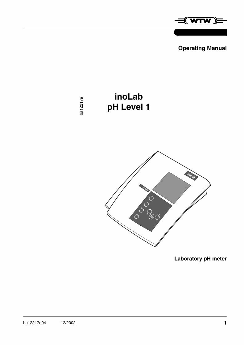
inoLab pH Level 1
ba12
217e
Operating Manual
Laboratory pH meter
ba12217e04 12/2002 1

Accuracy whengoing to press
The use of advanced technology and the high quality stan-dard of our instruments are the result of continuous develop-ment. This may result in differences between this operating manual and your instrument. We cannot guarantee that there are absolutely no errors in this manual. We are sure you will understand that we cannot accept any legal claims resulting from the data, figures or descriptions.
Warrantydeclaration
The designated instrument is covered by a warranty of three years from the date of purchase. The instrument warranty extends to manufacturing faults that are determined within the period of warranty. The warranty excludes components that are replaced during maintenance such as batteries, etc.
The warranty claim extends to restoring the instrument to readiness for use but not, however, to any further claim for damages. Improper handling or unauthorized opening of the instrument invalidates any warranty claim.
To ascertain the warranty liability, return the instrument and proof of purchase together with the date of purchase freight paid or prepaid.
Copyright © Weilheim 2002, WTW GmbH & Co. KGReprinting - even as excerpts - is only allowed with the ex-plicit written authorization of WTW GmbH & Co. KG, Weil-heim.Printed in Germany.
2

List of contents
1 Overview . . . . . . . . . . . . . . . . . . . . . . . . . . . . . . . . . 51.1 Keyboard . . . . . . . . . . . . . . . . . . . . . . . . . . . . . . . . .61.2 Display . . . . . . . . . . . . . . . . . . . . . . . . . . . . . . . . . . .7
1.3 Sockets . . . . . . . . . . . . . . . . . . . . . . . . . . . . . . . . . .7
2 Safety . . . . . . . . . . . . . . . . . . . . . . . . . . . . . . . . . . . 92.1 Authorized use . . . . . . . . . . . . . . . . . . . . . . . . . . .10
2.2 General safety instructions . . . . . . . . . . . . . . . . . .10
3 Commissioning . . . . . . . . . . . . . . . . . . . . . . . . . . 133.1 Scope of delivery . . . . . . . . . . . . . . . . . . . . . . . . . .13
3.2 Initial commissioning . . . . . . . . . . . . . . . . . . . . . . .13
4 Operation . . . . . . . . . . . . . . . . . . . . . . . . . . . . . . . 154.1 Switch on the instrument . . . . . . . . . . . . . . . . . . . .154.2 Measuring . . . . . . . . . . . . . . . . . . . . . . . . . . . . . . .16
4.2.1 Measuring the pH value . . . . . . . . . . . . . . .174.2.2 Measuring the Redox voltage . . . . . . . . . . .18
4.3 Calibrating . . . . . . . . . . . . . . . . . . . . . . . . . . . . . . .194.3.1 AutoCal TEC . . . . . . . . . . . . . . . . . . . . . . .214.3.2 AutoCal DIN . . . . . . . . . . . . . . . . . . . . . . . .234.3.3 ConCal . . . . . . . . . . . . . . . . . . . . . . . . . . . .25
4.4 Reset . . . . . . . . . . . . . . . . . . . . . . . . . . . . . . . . . . .28
5 Maintenance, cleaning, disposal . . . . . . . . . . . . 295.1 Maintenance . . . . . . . . . . . . . . . . . . . . . . . . . . . . .295.2 Cleaning . . . . . . . . . . . . . . . . . . . . . . . . . . . . . . . .30
5.3 Disposal . . . . . . . . . . . . . . . . . . . . . . . . . . . . . . . . .30
6 What to do if... . . . . . . . . . . . . . . . . . . . . . . . . . . . 31
7 Technical Data . . . . . . . . . . . . . . . . . . . . . . . . . . . 35
8 Lists . . . . . . . . . . . . . . . . . . . . . . . . . . . . . . . . . . . 39
9 Appendix . . . . . . . . . . . . . . . . . . . . . . . . . . . . . . . 45
3

List of contents
4

Overview
1 Overview
The compact inoLab pH Level 1 precision pH meter lets you perform pH measurements rapidly and reliably. The inoLab pH Level 1 provides the highest degree of oper-ating comfort, reliability and measuring safety for all applica-tions.
The proven MultiCal® calibration procedures and special AutoRead function support your work with the pH meter.
NoteThe measuring instrument can also be delivered as part of a set. Information on this and other accessories is available in the WTW catalog LABORATORY AND FIELD INSTRUMENTATION or via the Internet.
1 Keypad
2 Display
3 Sockets
3
2
1
5

Overview
1.1 Keyboard
1 Activate/deactivate AutoRead function
2 Call up calibration procedure
3 Select measuring mode
4 Measuring instrument ON/OFF
5 Reduce values, scroll
6 Increase values, scroll
7 Confirm inputs, start AutoRead
1
2
3
4
5
6
7
6

Overview
1.2 Display
1.3 Sockets
CautionOnly connect probes to the instrument that cannot feed ex-cessive voltages or currents (> SELV and > circuit with cur-rent limiter). Almost all commercial electrodes - especially WTW elec-trodes - meet these requirements.
Connectors:
1 pH electrode
2 Temperature probe
3 Reference electrode
4 Plug-in power supply (option)
Status line
Measured value display
Function and temperature display
Electrode symbol
1
23
4
7

Overview
8

Safety
2 Safety
This operating manual contains basic instructions that you must follow during the commissioning, operation and main-tenance of the pH meter. Consequently, all responsible per-sonnel must read this operating manual before working with the instrument. The operating manual must always be available within the vicinity of the instrument.
Target group This measuring instrument was developed for use in the lab-oratory. Thus, we assume that, as a result of their professional train-ing and experience, the operators will know the necessary safety precautions to take when handling chemicals.
Symbols used
Cautionindicates instructions that have to be followed to prevent damage to your instrument.
Warningindicates instructions that have to be followed to protect yourself and the instrument from dangerous electrical volt-age.
NoteIndicates notes that draw your attention to special features.
NoteIndicates cross-references to other documents, e.g. appli-cation reports, operating manuals of combination elec-trodes, etc.
9

Safety
2.1 Authorized useThis instrument is authorized exclusively for pH and Redox measurements in the laboratory. The technical specifications as given in chapter 7 TECHNICAL DATA must be observed. Only the operation and running of the measuring instrument according to the instructions given in this operating manual is authorized.Any other use is considered unauthorized.
2.2 General safety instructionsThis instrument is constructed and tested in compliance with the EN 61010-1 safety regulations for electronic measuring instruments. It left the factory in a safe and secure technical condition.
Function and opera-tional safety
The smooth functioning and operational safety of the instru-ment can only be guaranteed if the generally applicable safety measures and the specific safety instructions in this operating manual are followed.
The smooth functioning and operational safety of the instru-ment can only be guaranteed under the climatic conditions specified in chapter 7 TECHNICAL DATA.
If the instrument was transported from a cold environment to a warm environment, the formation of condensate can lead to the faulty functioning of the instrument. In this event, wait until the temperature of the instrument reaches room tem-perature before putting the instrument back into operation.
CautionThe instrument is only allowed to be opened by personnel authorized by WTW.
10

Safety
Safe operation If safe operation is no longer possible, the instrument must be taken out of service and secured against inadvertent op-eration.Safe operation is no longer possible if:
� the instrument has been damaged in transport
� the instrument has been stored under adverse conditions for a lengthy period of time
� the instrument is visibly damaged
� the instrument no longer operates as described in this manual.
If you are in doubt contact the supplier of the instrument.
Obligations of theoperator
The operator of this measuring instrument must ensure that the following laws and guidelines are observed when using dangerous substances:
� EEC directives for protective labor legislation
� National protective labor legislation
� Safety regulations
� Safety datasheets of the chemical manufacturer.
11

Safety
12

Commissioning
3 Commissioning
3.1 Scope of delivery� Laboratory measuring instrument, inoLab pH Level 1
� Operating manual and short manual
� 4 x type AA Mignon 1.5 V batteries
3.2 Initial commissioningPerform the following activities:
� Set the °C or °F
� Set the resolution
� Connect the plug-in power supply (optional).
Setting °C or °F The temperature can be displayed in °C or in °F . In the de-livery condition, the measuring instrument is preset to °C. To change the unit proceed as follows:
1 Switch the measuring instrument off.
2 Press and hold down the m key.
3 Press the e key.
4 Toggle between °C and °F by pressing u d.
5 Confirm with g.The measuring instrument switches to the measuring mode.
13
Commissioning
Connecting theplug-in power
supply (optional)
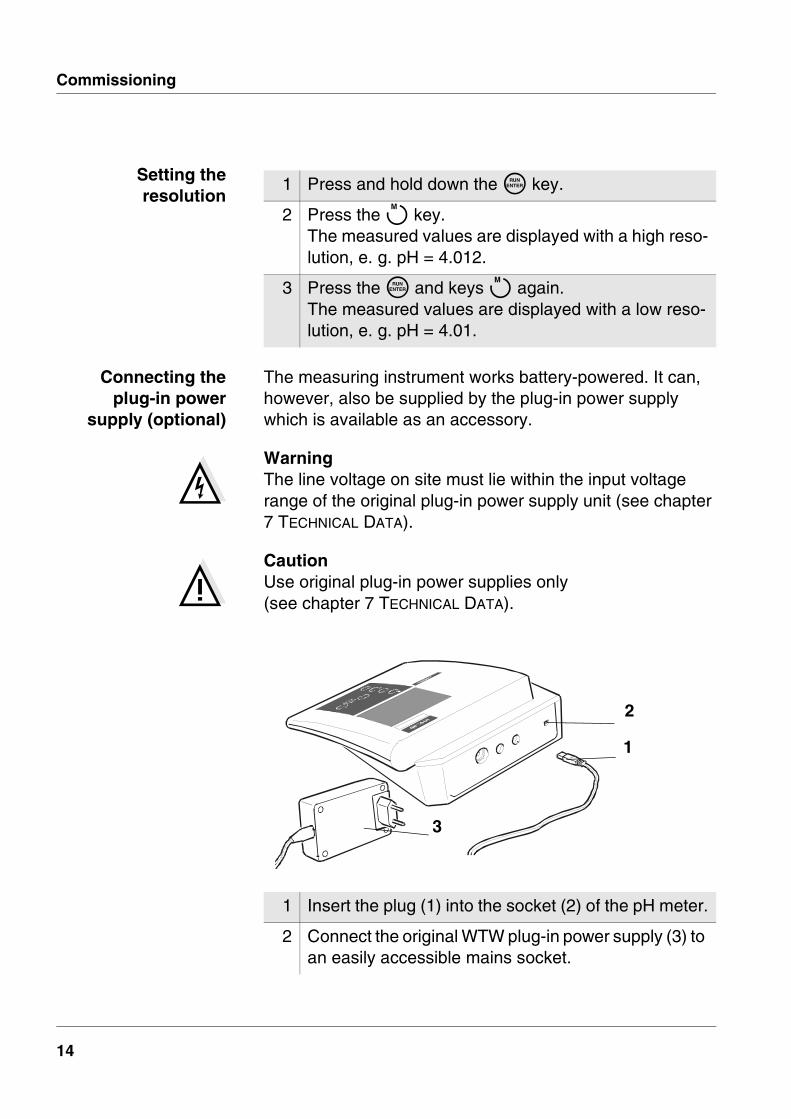
The measuring instrument works battery-powered. It can, however, also be supplied by the plug-in power supply which is available as an accessory.
WarningThe line voltage on site must lie within the input voltage range of the original plug-in power supply unit (see chapter 7 TECHNICAL DATA).
CautionUse original plug-in power supplies only (see chapter 7 TECHNICAL DATA).
1 Press and hold down the g key.
2 Press the m key.The measured values are displayed with a high reso-lution, e. g. pH = 4.012.
3 Press the g and keys m again.The measured values are displayed with a low reso-lution, e. g. pH = 4.01.
Setting theresolution
1 Insert the plug (1) into the socket (2) of the pH meter.
2 Connect the original WTW plug-in power supply (3) to an easily accessible mains socket.
1
2
3
14

Operation
4 Operation
4.1 Switch on the instrument
NoteThe instrument has an energy saving feature to avoid un-necessary battery depletion. The energy saving feature switches the instrument off if no key has been pressed for an hour.The energy saving feature is not active if the instrument is supplied by the plug-in power supply.
1 Place the instrument on a flat surface and protect it against intense light and heat.
2 Press the e key.The Display test appears briefly on the display.The instrument then switches automatically to the previously selected measuring mode.
3 Connect the pH electrode to the instrument. The measuring instrument is ready for operation.
15

Operation
4.2 MeasuringPreparatory
activitiesPerform the following activities when you want to measure:
NoteIncorrect calibration of the pH electrode will result in incor-rect measured values. Therefore, regularly perform calibra-tion before measuring.
Temperature probe Measurements can be performed with and without a temper-ature probe. A connected temperature probe is indicated by TP on the display.
NoteThe pH meter automatically recognizes the type of the tem-perature probe used. As a result, you can connect elec-trodes with the NTC30 or Pt1000.
The temperature measurement is absolutely essential for a reproducible pH measurement. If the measurement is made without a temperature probe, proceed as follows:
NoteWhen calibrating without a temperature probe, set up the current temperature of the respective buffer solution manu-ally by pressing the u d keys.
1 Connect the pH electrode to the instrument.
2 Adjust the temperature of the buffer or test solutions or measure the current temperature if the measure-ment is made without a temperature probe.
3 Calibrate or check the instrument with the pH elec-trode.
4 Select the measuring mode by pressing m.
1 Determine the current temperature using a thermo-meter.
2 Set up the temperature by pressing u d.
16

Operation
4.2.1 Measuring the pH value
AutoRead AR(Drift control)
The AutoRead function (drift control) checks the stability of the measurement signal. The stability has a considerable ef-fect on the reproducibility of the measured values.
For identical measurement conditions, the following criteria apply:� pH value: better than 0.02 (setting time: > 30 s)
1 Perform the preparatory activities according to sec-tion 4.2.
2 Immerse the pH electrode into the test sample.
3 Press the m key until pH appears in the status dis-play. The pH value appears on the display.
1 Call up the pH measuring mode by pressing m.
2 Activate the AutoRead function by pressing a.The current measured value is frozen (Hold function).
3 Start the AutoRead function by pressing g.AR flashes on the display until a stable measured val-ue is reached.
4 If necessary, start the next AutoRead measurement by pressing g.
5 To terminate the AutoRead function: Press the a key.
17
Operation
NoteThe current AutoRead measurement (with acceptance of the current value) can be terminated at any time by pressing g.
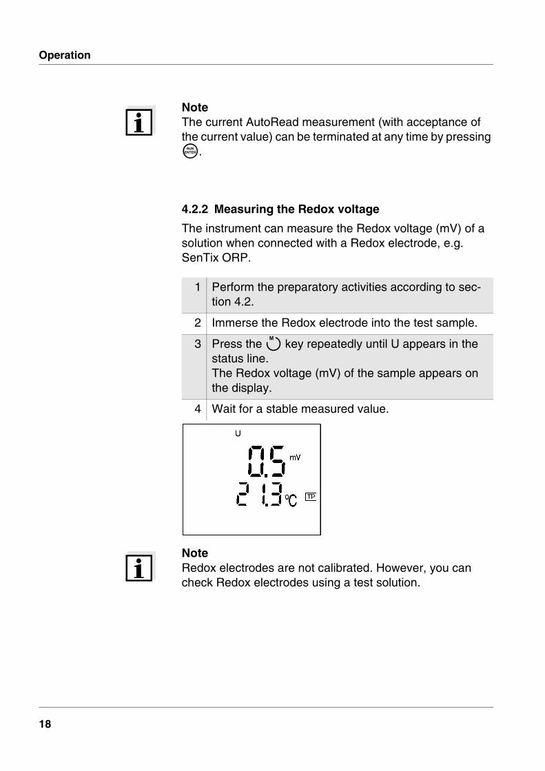
4.2.2 Measuring the Redox voltage
The instrument can measure the Redox voltage (mV) of a solution when connected with a Redox electrode, e.g. SenTix ORP.
NoteRedox electrodes are not calibrated. However, you can check Redox electrodes using a test solution.
1 Perform the preparatory activities according to sec-tion 4.2.
2 Immerse the Redox electrode into the test sample.
3 Press the m key repeatedly until U appears in the status line. The Redox voltage (mV) of the sample appears on the display.
4 Wait for a stable measured value.
18

Operation
4.3 CalibratingWhy calibrate? pH electrodes age. This changes the asymmetry (zero
point) and slope of the pH electrode. As a result, an inexact measured value is displayed. Calibration determines the current values of the asymmetry and slope of the electrode and they are stored in the instrument. Thus, you should calibrate at regular intervals.
When to calibrate? � After connecting another electrode
� When the sensor symbol flashes:
– after expiry of the calibration interval
– after a voltage interruption, e.g. battery change
You can choose between 3 calibration procedures:
AutoCal TEC is specially adapted to the WTW technical buffer solutions as a fully automatic two-point calibration. The buffer solu-tions are automatically recognized by the instrument.
AutoCal DIN is specially adapted to permanently programmed buffer so-lutions according to DIN 19266 as a fully automatic two-point calibration. The buffer solutions are automatically rec-ognized by the instrument.
ConCal is the conventional two-point calibration with 2 freely selectable buffer solutions or single-point calibration as the rapid method.
AutoRead In calibration using AutoCal TEC and AutoCal DIN, the Au-toRead function is automatically activated. The current AutoRead measurement (with acceptance of the current value) can be terminated at any time by pressing g.
19

Operation
Calibrationevaluation
After the calibration, the instrument automatically evaluates the current status. The asymmetry and slope are separately evaluated. The worst evaluation appears on the display.
Display Asymmetry [mV]
Slope [mV/pH]
-15 ... +15 -60.5 ... -58
-20 ... +20 -58 ... -57
-25 ... +25 -61 ... -60.5 or -57 ... -56
Clean the electrode accord-ing to the sensor operating manual
-30 ... +30 -62 ... -61or -56 ... -50
E3
Clear the fault according to chapter 6 WHAT TO DO IF...
< -30 or > 30
< -62 or > -50
1 Switch on the instrument by pressing e.
2 Connect the pH electrode to the instrument.
3 Keep the buffer solutions ready.
4 Adjust the temperature of the solutions and measure the current temperature if the measurement is per-formed without a temperature probe.
Preparatoryactivities
20

Operation
4.3.1 AutoCal TEC
Use any two of the WTW technical buffer solutions for this procedure.
NoteSteps 2 and 6 are not required if you use a temperature probe.
1 Press the c key repeatedly until the AutoCal TEC function display appears.
2 If necessary, set the temperature of the buffer solu-tion by pressing u d.
3 Submerse the pH electrode in the first buffer solution.
4 Press the g key.AR flashes on the display.The electrode voltage (mV) appears on the display. As soon as a stable value is recognized, Ct2 ap-pears.
5 Thoroughly rinse the electrode with distilled water.
21

Operation
6 If necessary, set the temperature of the second buffer solution by pressing u d.
7 Submerse the electrode in the second buffer solution.
8 Press the g key.AR flashes on the display. The electrode voltage (mV) appears on the display. As soon as a stable value is recognized, AR disap-pears. The sensor symbol shows the electrode evaluation after the two-point calibration. The value of the slope (mV/pH) appears on the dis-play.
9 Press the g key.The value of the asymmetry (mV) appears on the dis-play.
10 To return to the measuring mode: Press the m key.
22

Operation
4.3.2 AutoCal DIN
Use two different DIN buffer solutions (type A, C, D or F with the pH values 1.679, 4.006, 6.865, 9.180) for this procedure.
NoteSteps 2 and 6 are not required if you use a temperature probe.
1 Press the c key repeatedly until the AutoCal DIN function display appears.
2 If necessary, set the temperature of the buffer solu-tion by pressing u d.
3 Submerse the pH electrode in the first buffer solution.
4 Press the g key.AR flashes on the display.The electrode voltage (mV) appears on the display. As soon as a stable value is recognized, Cd2 ap-pears.
5 Thoroughly rinse the electrode with distilled water.
23

Operation
6 If necessary, set the temperature of the second buffer solution by pressing u d.
7 Submerse the electrode in the second buffer solution.
8 Press the g key.AR flashes on the display.The electrode voltage (mV) appears on the display. As soon as a stable value is recognized, AR disap-pears.The sensor symbol shows the electrode evaluation after the two-point calibration. The value of the slope (mV/pH) appears on the dis-play.
9 Press the g key.The value of the asymmetry (mV) appears on the dis-play.
10 To return to the measuring mode: Press the m key.
24

Operation
4.3.3 ConCal
Two-point calibration
Use two buffer solutions for this procedure:
� pH 7.0 ± 0.5
� any other buffer solution
NoteSteps 2 and 9 are not required if you use a temperature probe.
1 Press the c key repeatedly until the ConCal func-tion display appears.
2 If necessary, set the temperature of the buffer solu-tion by pressing u d.
3 Submerse the pH electrode in the pH 7.0 ± 0.5 buffer solution.
4 Press the g key.The measured pH value appears on the display.
5 Set the nominal pH value of the buffer solution (at the current temperature) by pressing the u d keys.
6 Press the g key.The value of the asymmetry (mV) and the sensor symbol appear on the display.
7 Press the g key.SLO(pe) appears on the display.
25

Operation
8 Thoroughly rinse the electrode with distilled water.
9 If necessary, set the temperature of the second buffer solution by pressing u d.
10 Submerse the electrode in the second buffer solution.
11 Press the g key.The second measured pH value appears on the dis-play.
12 Set the nominal pH value of the second buffer solu-tion (at the current temperature).
13 Press the g key.The value of the slope (mV/pH) appears on the dis-play. The sensor symbol shows the evaluation of the elec-trode after the two-point calibration.
14 Press the g key.The value of the asymmetry (mV) appears on the dis-play again.
15 To return to the measuring mode: Press the m key.
26

Operation
Single-point calibration
Use a buffer solution in the range pH = 7.0 ± 0.5 for this pro-cedure.
NoteOnly the electrode asymmetry is determined in single-point calibration. The slope of the last two-point calibration is re-tained.
NoteStep 2 is not required if you use a temperature probe. The TP display indicates an active temperature measurement.
1 Press the c key repeatedly until the ConCal func-tion display appears.
2 Set the temperature of the buffer solution by pressing u d.
3 Submerse the pH electrode in the buffer solution.
4 Press the g key.The measured pH value appears on the display.
5 Set the nominal pH value of the buffer solution (at the current temperature) by pressing the u d keys.
6 Press the g key.The value of the asymmetry (mV) and the sensor symbol for the evaluation of the electrode appears on the display.
7 To return to the measuring mode: Press the m key.
27

Operation
4.4 ResetBasic settings The following functions are reset (initialized) to the values
they had on delivery:
Proceed as follows:
Measuring mode pH
Asymmetry 0 mV
Slope -59.16 mV/pH
Calibration procedure AutoCal TEC
Temperature, manual 25°C
Resolution of pH display 0.01
1 Press and hold down the g key.
2 Press the c key.
3 Toggle between no and yes by pressing u d.yes: reset parameters.no: retain settings.
4 Confirm with g.The instrument changes automatically to the pH measuring mode.
28

Maintenance, cleaning, disposal
5 Maintenance, cleaning, disposal
5.1 MaintenanceThe measuring instrument is almost maintenance-free. The only maintenance task is replacing the batteries:
CautionMake sure that the poles of the batteries are the right way round.The ± signs in the battery compartment must correspond to the ± signs on the batteries. Only use leakproof alkaline manganese batteries.
NoteSee the relevant operating manual of the electrode for in-structions on maintenance.
1 Open the battery compartment (1) on the underside of the instrument.
2 Remove the four batteries from the battery compart-ment.
3 Insert four new batteries (Type Mignon AA) into the battery compartment.
4 Close the battery compartment (1).
1
29

Maintenance, cleaning, disposal
5.2 CleaningOccasionally wipe the outside of the measuring instrument with a damp, lint-free cloth. Disinfect the housing with iso-propanol as required.
CautionThe housing is made of synthetic material (ABS). Thus, avoid contact with acetone or similar detergents that contain solvents. Remove any splashes immediately.
5.3 DisposalPacking The measuring instrument is sent out in a protective trans-
port packing. We recommend: Keep the packing material. The original packing protects the instrument against damage during transport.
Batteries This note refers to the battery regulation that applies in the Federal Republic of Germany. We would ask end-consum-ers in other countries to follow their local statutory provi-sions.
NoteIn compliance with §14 of the BATTERY REGULATION, we would like to point out that this instrument contains batteries. Batteries that have been removed must only be disposed of at the recycling facility set up for this purpose or via the retail outlet. It is illegal to dispose of them in household refuse.
Measuringinstrument
Dispose of the measuring instrument as electronic waste at an appropriate collection point. It is illegal to dispose of them in household refuse.
30

What to do if...
6 What to do if...
Cause Remedy
pH electrode:
– Not connected – Connect electrode
– Air bubbles in front of the diaphragm
– Remove air bubbles
– Air in the diaphragm – Extract air or moisten diaphragm
– Cable broken – Replace electrode
– Gel electrolyte dried out – Replace electrode
Cause Remedy
pH electrode:
– Diaphragm contaminated – Clean diaphragm
– Membrane contaminated – Clean membrane
– Moisture in the plug – Dry plug
– Electrolyte obsolete – Replenish electrolyte or replace electrode
– Electrode obsolete – Replace electrode
– Electrode broken – Replace electrode
Measuring instrument:
– Incorrect calibration procedure
– Select correct procedure
– Incorrect solution temperature (without temperature probe)
– Set up correct temperature
– Socket damp – Dry socket
Error message,OFLOFLOFLOFL
Error message,E3E3E3E3
31

What to do if...
Buffer solutions:
– Incorrect buffer solutions – Change calibration procedure
– Buffer solutions too old – Only use once.Note the shelf life
– Buffer solutions depleted – Change solutions
Cause Remedy
pH electrode:
– Diaphragm contaminated – Clean diaphragm
– Membrane contaminated – Clean membrane
Sample:
– pH value not stable – Measure with air excluded if necessary
– Temperature not stable – Adjust temperature if necessary
Electrode + sample:
– Conductivity too low – Use suitable electrode
– Temperature too high – Use suitable electrode
– Organic liquids – Use suitable electrode
Cause Remedy
– Batteries almost depleted – Replace batteries(see section 5.1 MAINTENANCE)
No stablemeasured value
LoBat
32

What to do if...
You would like toknow which soft-
ware version is inthe instrument
Cause Remedy
pH electrode:
– pH electrode unsuitable – Use suitable electrode
– Temperature difference between buffer and sample too large
– Adjust temperature of buffers or samples
– Measuring procedure not suitable
– Follow special procedure
Cause Remedy
– Operating state undefined or EMC electric stress unallowed
– Processor reset:Press the a key and switch on instrument
Obviously incorrectmeasured values
Instrument does notreact to keystroke
Cause Remedy
– e.g. question of the WTW service department
– Press the a key and switch on instrument. The software version is displayed.
33

What to do if...
34

Technical Data
7 Technical Data
Storage temperature - 25 °C ... + 65 °C
Operating temperature 0 °C ... + 55 °C
Allowable relative hu-midity
Annual mean: < 75 %30 days/year: 95 %Other days: 85 %
pH - 2.000 ... + 19.999- 2.00 ... + 19.99
U [mV] - 999.9 ... + 999.9- 1999 ... + 1999
T [°C] - 5.0 ... + 105.0
T [°F] + 23.0 ... + 221.0
pH(in the measuring range of 2 pH units around the calibration point)
± 0.005 (at operating temper-ature + 15 °C ... + 35 °C )
± 0.01
U [mV] ± 0.3 (at + 15 °C ... + 35 °C)± 1
T [°C] NTC 30: ± 0.1
PT 1000:± 0.5 at 0 °C ... 15 °C ± 0.1 at 15 °C ... 35 °C± 1 at 35 °C ... 55 °C
T [°F] NTC 30: ± 0.2
PT 1000:± 0.9 at 32 °F ... 59 °F ± 0.2 at 59 °F ... 95 °F± 1.8 at 95 °F ... 131 °F
Ambienttemperature
Measuring rangesand resolution
Accuracy(± 1 digit)
35

Technical Data
Length [mm] 230
Width [mm] 210
Height [mm] 70
Weight [kg] Approx. 0.850
Batteries 4 x 1.5 V AA type alkaline manga-nese batteries
Runtime Approx. 3000 operating hours
Mains power supply (option)
Connection max. overvoltage cate-gory II (valid for all plug-in power supplies):
Plug-in power supply (Euro plug):FRIWO FW1199, 11.7864Friwo Part. No. 1762613Input: 230 V ~ / 50 Hz / 5.6 VAOutput: 12 V = / 130 mA / 1.56 VA
Plug-in power supply (US plug):FRIWO FW1199, 11.7880Friwo Part. No. 1794043Input: 120 V ~ / 60 Hz / 6 VAOutput: 12 V = / 150 mA
Plug-in power supply (UK plug):FRIWO FW3288, 11.8453Friwo Part No. 1816491Input: 230V ~ / 50 Hz / 23 VAOutput: 12 V = / 130 mA / 1,56 VA
Dimensions andweight
Energy supply
36

Technical Data
EMC E.C. guideline 89/336/EECEN 61326-1:1997EN 61000-3-2 A14:2000EN 61000-3-3:1995FCC Class A
Instrument safety E.C. guideline 73/23/EEC
Protective class 3, EN 61010-1 A2:1995
Climatic class 2, VDI/VDE 3540
TÜV GS, UL/CUL, CE
Guidelinesand norms used
Test marks
37

Technical Data
38

Lists
8 Lists
This chapter provides additional information and orientation aids.
Abbreviations The list of abbreviations explains abbreviations that appear on the display or when dealing with the instrument.
Specialist terms The glossary briefly explains the meaning of the specialist terms. However, terms that should already be familiar to the target group are not described here.
Index The index helps you find the topics that you are looking for.
39

Lists
Abbreviations
AR AutoRead (drift control)
ARng Automatic range switchingMeasuring instrument measures with high-est resolution
ASY Asymmetry
AutoCal DIN Automatic calibration with DIN buffer solu-tions
AutoCal TEC Automatic calibration with WTW technical buffer solutions
Cal Calibration
Cd... Calibration withDIN buffer solutions (acc. to DIN 19 266)
ConCal Conventional one/two point calibration
Ct... Calibration with WTW technical buffer so-lutions
E3 Error message (see WHAT TO DO IF ...)
InI InitializationResets individual basic functions to the status they had on delivery
LoBat Low BatteryBatteries are almost empty
mV Voltage unit
mV/pH Unit of the electrode slope
OFL OverflowDisplay range exceeded
pH pH value
S Slope
SELV Safety Extra Low Voltage
40

Lists
SLO SlopeSlope setting on calibration
TP Temperature probeTemperature measurement active
UASY Asymmetry potential
°C Temperature unit, °Celsius
°F Temperature unit, Fahrenheit
41
Lists
Glossary
Asymmetry Zero point of a pH electrode.
AutoRead Monitors the electrode drift and releases the measured val-ue only after the stability criterion has been reached. In this way, this procedure ensures the highest degree of precision and reproducibility.
Buffer solution Stable solution with a precisely known pH value.
Diaphragm Contact point between the reference electrolytic solution and the sample.
Drift control See AUTOREAD.
MultiCal® Group term for the various WTW calibration procedures used for automatic calibration in buffer solutions.
Redox voltage Potentiometric quantity.
Resolution Number of decimal places that appear for a measured val-ue.
Slope Specifies the voltage change per pH unit.
Test solution Stable solution with a precisely known Redox voltage.
42

Lists
Index
Aasymmetry 19authorized use 10AutoCal DIN 19, 23AutoCal TEC 19, 21AutoRead 17
Bbasic settings 28battery compartment 29
Ccalibrating 19calibration evaluation 20calibration procedures 19ConCal 19, 25
Ddelivery condition 28display 7drift control 17
Eelectrode symbol 7energy saving feature 15error messages 31
Iinitial commissioning 13initialize 28
Kkeys 6
LLoBat 32
Ooperational safety 10
Pplace of the instrument 15plug-in power supply 14
RRedox electrode 18Redox voltage 18replacing the batteries 29reset 28
Ssafety 9safety precautions 9scope of delivery 13setting the resolution 14setting the temperature unit 13single-point calibration 19
ConCal 27slope 19sockets 7
Ttemperature probe 16two-point calibration 19
AutoCal DIN 24AutoCal TEC 22ConCal 25
43

Lists
44

Appendix
9 Appendix
45

Appendix
NoteIf you need further informationen or application notes you can ask for:
� Application reports
� Primers
� Safety data sheets.
You can find information on available literature in the WTW catalog, LABORATORY AND FIELD INSTRUMENTATION or via the Internet.
46
Recommended


![[XLS]Formular für Kundenregistrierung und … · Web viewPR 12 Prensa 289 Prensa 417 Sacmi PRENSA PR 02 PH 1400 PH 1500 PH 1890 PH 2090 PH 2590 PH 680 PH 690 PH 980 CCM 01 PH 2800](https://img.dokumen.tips/doc/110x75/5aed860e7f8b9a6625900e1f/xlsformular-fr-kundenregistrierung-und-viewpr-12-prensa-289-prensa-417-sacmi.jpg)


