ICW-6 Window IntercomInstallation and Operation Instructions
93507855000 Rev D 2/2010
Proprietary Notice
The product information and design disclosed herein were originated by and are the property of Bosch Security Systems, Inc. Bosch reserves all patent, proprietary design, manufacturing, reproduction, use and sales rights thereto, and to any article disclosed therein, except to the extent rights are expressly granted to others.
Copyright Notice
Copyright 2010 by Bosch Security Systems, Inc. All rights reserved. Reproduction, in whole or in part, without prior written permission from Bosch is prohibited.
Warranty Notice
See the enclosed warranty card for further details.
Customer Support
Technical questions should be directed to:
Customer Service DepartmentBosch Security Systems, Inc.12000 Portland Avenue SouthBurnsville, MN 55337 USATelephone: 800-392-3497Fax: 800-323-0498Factory Service: 800-553-5992
Return Shipping Instructions
Parts & Service DepartmentBosch Security Systems, Inc. (Lincoln, NE)Telephone: 402-467-5321Fax: 402-467-3279Factory Service: 800-553-5992
Please include a note in the box which supplies the company name, address, phone number, a person to contact regarding the repair, the type and quantity of equipment, a description of the problem and the serial number(s).
Shipping to the Manufacturer
All shipments of product should be made via UPS Ground, prepaid (you may request from Factory Service a different shipment method). Any shipment upgrades will be paid by the customer. The equipment should be shipped in the original packing carton. If the original carton is not available, use any suitable container that is rigid and of adequate size. If a substitute container is used, the equipment should be wrapped in paper and surrounded with at least four (4) inches of excelsior or similar shock-absorbing material. All shipments must be sent to the following address and must include the Proof of Purchase for warranty repair. Upon completion of any repair the equipment will be returned via United Parcel Service or specified shipper, collect.
Factory Service DepartmentBosch Security Systems, Inc.8601 East Cornhusker Hwy.Lincoln, NE 68507 U.S.A.Attn: Service

Tableof
Contents
Introduction .......................................................................................... 3Unpacking and Inspection ................................................................... 3Recommended Items ............................................................................ 4Specifications ....................................................................................... 4Accessories .......................................................................................... 5
Installation and Operation .................................................................... 7Installation ........................................................................................... 7Operation ........................................................................................... 11Inside and Outside Mic Adjustment Pot ............................................ 11Mic Adjustment Pot Location ............................................................ 11

CHAPTER 1
Introduction
IMPORTANT: Use the power supply included with the ICW-6. Use of any other power supply could damage the ICW-6 and will void the warranty.
Unpacking and Inspection
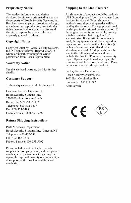
Unpack the equipment from the shipping case and inspect for missing or damaged components. You should have all of the items listed in Figure 1 .
ICW-6 PackageA. Cordset - EuropeanB. Cordset - U.S.A.C. ICW-6 Final Assembly
1. Operator-Side Assembly2. Customer-Side Assembly
D. Switching Power SupplyE. Installation Kit
• #6 screws 1” (3)• #6 washers (3)• Cable Tie
F. User Manual (not shown)G. Mounting Template (not shown)H. Quick Start Guide (not shown)I. Warranty Card (not shown)
FIGURE 1. ICW-6 System Components
Introduction 3
Recommended Items• No.1 Phillips screwdriver• Equipment for cutting/drilling hole(s) for mounting (See Installation
section for details)• 1” wide transparent tape• Scissors (For cutting the mounting template from the last page).
SpecificationsGeneral
Power Requirement
50mA max @ 110-240VAC, 5VDC 600mA maximum
System Frequency Response
200 to 4.5 kHz ±3 dB
Environmental
-20° C to 55° C, 0% to 90% humidity, non-condensing
Outputs
External Speaker
2W: 100dB SPL at 1ft. at 1 kHz, C weighting
Internal Speaker
2W: 100dB SPL at 1ft. at 1 kHz, C weighting
Note: These are sine wave maximums. Voice measurements will range 70 to 90 dB SPL.
Headphones
80 mW: 100dB peak SPL
Voice Range: 84 to 104 dB SPL
Impedance: 50 Ω
Inputs
Internal Panel Microphone
Electret: 4 mv at 1kHz, typical into 1000 ohms source impedance
External Headset Microphone
Dynamic: range 4 mv at 1kHz, typical into 200 ohmsSource Impedance Dynamic: 200 ohms
Options
Gooseneck Microphone
MCP-90-3, MCP-90-8, MCP-90-12, MCP-90-18
Headsets
PH-44-IC3 (Dual Headphone), PH-88-IC3 (Single Headphone)
4

Accessories
Description Part NumberMCP-90-12 301029000
MCP-90-18 301030000
PH-88-IC3 300852300
PH-44-IC3 300853300
PH-88-IC3-QD 300853301
PH-44-IC3-QD 300853300
5

6

CHAPTER 2
Installation andOperation
Installation1. Remove the two (2) screws holding the mounting plate to the operator assembly.
(See Figure 2 .)2. Measure and identify the location where the intercom is to be mounted.
FIGURE 2. ICW-6 Assembly Detail
Installation and Operation 7
3. Attach the mounting template (supplied in box) to the window (customer assembly side) being sure to center the appropriate guide in the location identified in step 2.
NOTE: Use either the single large hole, or multiple small holes depending on which method you choose. Using the multiple small hole method with bullet-proof glass will afford maximum operator protection (Figure 4).
4. Cut and/or drill the hole(s) from the customer assembly side.5. Have an assistant place the customer assembly against the window. Make sure
the holes line up correctly. 6. Attach the mounting plate removed from the operator assembly (See Step 1)
using the three (3) supplied mounting screws and rubber washers. (See Figure 5).7. Remove the lower left screw and washer and attach the ground wire (See Figure 6.8. Attach the cable harness from the customer assembly to the connector on the
operator assembly (See Figure 6).9. Attach the operator assembly to the mounting plate using the screws removed
in Step 1.10. Screw the threaded end of the ICW-6 power supply interface cord into the ICW-
6. The connector is located on the bottom of the ICW-6 on the operator assembly side.
11. Secure the cord to the glass using wide clear adhesive tape.12. Connect the power supply to AC power using the supplied IEC cord. 13. Attach the ICW-6’s power cord to the power supply.
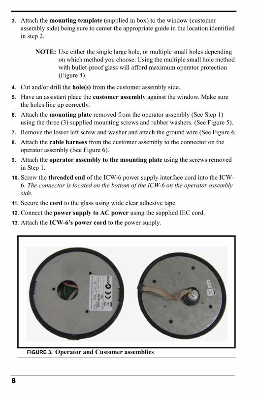
FIGURE 3. Operator and Customer assemblies
8

FIGURE 4. Mounting Template
FIGURE 5. Customer Side Mounted
9

FIGURE 6. Connecting customer and operator assemblies prior to final mounting.
10
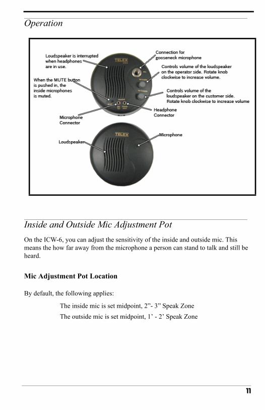
Operation
Inside and Outside Mic Adjustment PotOn the ICW-6, you can adjust the sensitivity of the inside and outside mic. This means the how far away from the microphone a person can stand to talk and still be heard.
Mic Adjustment Pot Location
By default, the following applies:
The inside mic is set midpoint, 2”- 3” Speak ZoneThe outside mic is set midpoint, 1’ - 2’ Speak Zone
11
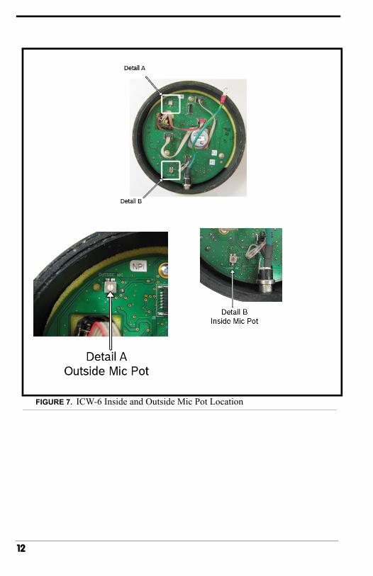
FIGURE 7. ICW-6 Inside and Outside Mic Pot Location
12

To adjust the inside or outside mic sensitivity level, do the following:
1. Using a small screwdriver, remove the two (2) side screws from the operator side unit.
2. Carefully remove the back plate from the operator side unit.3. Using Figure 7 , locate the mic pot you want to adjust.4. With a flathead screwdriver, turn the mic pot clockwise to increase the
sensitivity.ORTurn the mic pot counter-clockwise to decrease the sensitivity.
FIGURE 8. Side Screws Holding the Back Plate to the Operator Unit
13

Recommended