1071-5819/$ - se
doi:10.1016/j.ijh
�CorrespondE-mail addr
Int. J. Human-Computer Studies 69 (2011) 201–219
www.elsevier.com/locate/ijhcs
Human–computer interaction for the generation of imageprocessing applications
Regis Clouard�, Arnaud Renouf, Marinette Revenu
GREYC (ENSICAEN and University of Caen), 6, boulevard Marechal Juin, 14050 Caen, France
Received 15 May 2009; received in revised form 29 October 2010; accepted 4 December 2010
Communicated by N. Aussenac-Gilles
Available online 17 December 2010
Abstract
The development of customized image processing applications is time consuming and requires high level skills. This paper describes the
design of an interactive application generation system oriented towards producing image processing software programs. The description is
focused on twomodels which constitute the core of the human–computer interaction. First, the formulation model identifies and organizes
information that is assumed necessary and sufficient for developing image processing applications. This model is represented as a domain
ontology which provides primitives for the formulation language. Second, the interaction model defines ways to acquire such information
from end-users. The result of the interaction is an application ontology from which a suitable software is generated. This model emphases
the gradual emergence of a semantics of the problem through purely symbolic representations. Based on these two models, a prototype
system has been implemented to conduct experiments.
& 2010 Elsevier Ltd. All rights reserved.
Keywords: Human–computer interaction; Knowledge acquisition; Ontology design; Image processing and computer vision
1. Introduction
The development of image processing applications hasproven to be a highly complex and time consuming activity.This prevents the penetration of image processing intoindustry, whereas the demand for concrete applications isgrowing in all domains: medicine, biotechnology, remotesensing, astronomy, ecology, security, forensics, chemistry,surveillance, quality control, etc. As a result, it is becomingimportant to develop systems that can help end-users buildcustomized applications. The challenge is to allow end-usersto program software at the image feature level rather than atthe computer code level.
This paper is meant as a contribution to the developmentof a system oriented towards producing customized soft-ware programs for image processing applications. Such asystem is first configured ‘‘off-line’’ by image processingexperts, with resources required to process images in a givenapplication domain, for example segmentation of cytology
e front matter & 2010 Elsevier Ltd. All rights reserved.
cs.2010.12.002
ing author.
ess: [email protected] (R. Clouard).
images. Then, the system is distributed to end-users of thetarget domain, for example cytotechnologists. Users interact‘‘on-line’’ with the system to autonomously produce con-crete applications in the target domain. Their role is focusedon query formulation.In absence of consensus on a clear-cut boundary of the
image processing field, we supply our own definition so as todelineate the project scope.
Definition 1. Image processing is any form of image-to-image transformations without any interpretation of con-tent, for which input data are iconic images and output dataare iconic, intrinsic, or segmented images.
Our definition locates image processing applications as onecomponent of the low level part of more global image analysisor computer vision systems. Thus, image processing is not anend in itself and it has no decision-making authority. Its role iscompletely determined by the high-level part which uses itsresults to perform interpretation, visualization, storage, ortransmission of image data. Definition 1 is stated from thepoint of view of the transformation objectives and the inputimage types. It is narrower than other definitions available in

R. Clouard et al. / Int. J. Human-Computer Studies 69 (2011) 201–219202
the literature (e.g., Russ, 2006; Pratt, 2007; Gonzalez andWoods, 2008), and excludes higher level categories ofobjectives such as feature extraction, object classification,and object recognition. Only six categories of objectives areconsidered:
�
Fig
Ho
Restoration objectives refer to recovery of an originalimage from degraded observations, knowing the degra-dation phenomenon.
� Enhancement objectives concern the improvement of thevisual quality of images.
� Compression objectives address problems related to thereduction of the amount of data needed to store adigital image.
� Reconstruction objectives intend to infer new spatiotem-poral information such as shape, 3D, and motion.
� Segmentation objectives aim at structuring signal infor-mation into more abstract primitives such as regions,contours, and points of interest.
� Detection objectives seek to build positive masks thatlocate information of interest.
These six objectives are considered independent. However,Definition 1 makes no assumption about the way they maybe achieved. For example, an image segmentation programcan be implemented by means of restoration, enhancement,and feature extraction operations.
An image processing application is devoted to one of theabove mentioned objectives and one class of ‘‘similar’’images. Consider the following image analysis applicationthat will be used as a running example throughout thispaper. It is a biological application in the context of cancerscreening described in Lezoray and Cardot (2000). Thepurpose is to assist cytotechnologists in finding suspect orabnormal cells from the analysis of serous cytology images.Within this image analysis application, the specific imageprocessing objective is to segment images into regionscorresponding to individual cells. Then, the resulting regionswill be fed into a classifier which has been trained to identifythe various cellular types. The image class (see examplesFig. 1) is composed of color images of serous effusionsacquired by an optical microscope always under the sameresolution and illumination conditions.
Within application generation systems, the interfacebetween human and computer plays a preponderant role.
. 1. Four samples of microscopic images of serous effusions. (Reproduced by
spital Center of Cotentin.)
This interface is the only means to take into account end-user requirements. Its expressive power determines the scopeof the system and its degree of compliance with the userrequirements. In this paper, we argue that the formulationinterface must be more than a simple passive control panelthat exhibits the elements identified as necessary for carryingout the solutions stored into the system. Indeed, throughsuch control panels, users believe they develop customizedapplications, but in fact they only choose and parameterizeready-made ones. Actually, the preexisting solutions arehidden under a predefined list of task names exposed on theinterface, and the parameters are hidden under a predefinedlist of image features to be set. Thus, the query is composedwith the same list of features for every problem, only featurevalues may change.On the contrary, to cope with unanticipated problems
and to develop genuine customized software programs, thesolution and the query should be built incrementally bycomplementarity between the user and the system (Zou andNagy, 2006). The query should be composed with onlyrelevant features, and the program should be constructed byaggregation of solution elements according to the querycomposition. In this new perspective, the interface provides aformal language that allows for rich formulation of applica-tion problems, and organizes the cooperative problem-solving process by dynamically linking user formulationelements to solution elements provided by the system. As aresult, the final software program is the best compromisebetween user intentions and system processing capabilities.This idea has been in use in interactive image segmenta-
tion for a long time (Udupa, 1982), and more recently inimage retrieval (Smeulders et al., 2000; Santini et al., 2001).But it is difficult to implement in the case of interactiveconstruction of image processing applications. The maindifficulty stems from the need to design a solution that willsuit a whole class of images, and not only a single image.Some recent works have been undertaken with the idea ofcomplementarity between human and computer for theinteractive development of image processing applications,such as those of Draper et al. (1999), Levner et al. (2003),Nouvel (2002), or Hudelot et al. (2005). But to reducecomplexity, these systems remain limited to sole cases ofimage segmentation problems where the concept of describ-able and measurable objects of interest exists in the scene.Our goal is to propose a general purpose system that
covers all the image processing objectives as stated in
courtesy of the Pathological Anatomy and Cytology Department of the Public
R. Clouard et al. / Int. J. Human-Computer Studies 69 (2011) 201–219 203
Definition 1, and that is domain-independent. In its currentstate, the system is limited to 2D and 3D still images. If usersno longer have to be image processing experts, they still needto have image processing skills, since they have to identifywhat image information is relevant for performing accurateprocessing.
This paper is focused on the definition of two models thatare the prerequisite for the design of such interactivesystems: the formulation model and the human–computerinteraction model. The formulation model identifies whatkind of information is necessary and sufficient for the systemto produce customized software programs. This modelprovides the basis for the definition of a query language.The interaction model identifies ways to collect this infor-mation from users in order to compose queries. However,problems raised by the generation of the software solution aswell as those raised by the evaluation of the image processingresults are beyond the scope of the paper. The rest of thepaper is organized as follows. Section 2 first discusses theproblematics of the formulation of image processing objec-tives and then presents a review of various approaches toaddress this issue. Our formulation model is detailed inSection 3. The formal representation of formulation infor-mation rests on a domain ontology, which is presented inSection 4. Section 5 details the human–computer interactionmodel and the means to acquire formulation informationfrom end-users. Then, experiments and discussion of theresults are given in Section 6. Finally, conclusions and futuredirections of research are presented in Section 7.
2. Image processing formulation problematics
The purpose of this section is to explain why it is socomplex to provide formulations of image processingapplications and to review some approaches from theliterature.
2.1. Why image processing application formulation is
necessary?
Inferred from Definition 1, we propose the followingdefinition of image processing application, stated from afunctional standpoint:
Definition 2. An image processing application is a softwarespecialized in the achievement of a given image transforma-tion goal from input images belonging to a given class.
This definition clearly determines an image processingapplication by one image transformation goal and one image
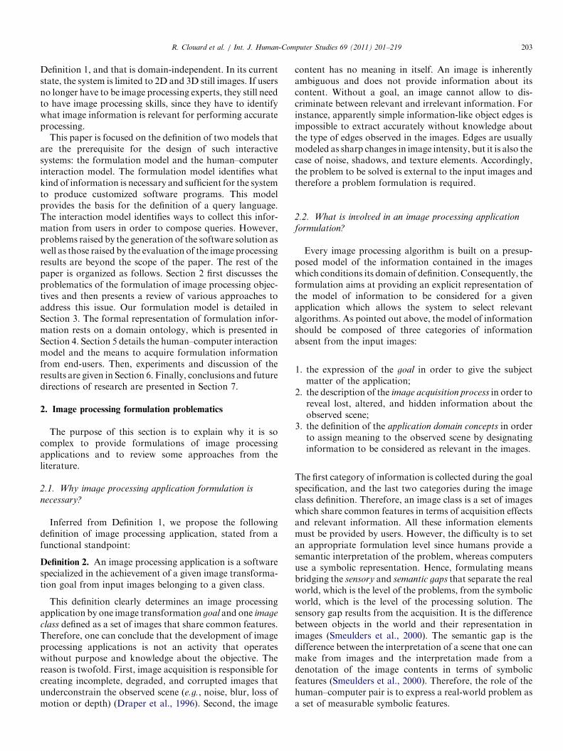
class defined as a set of images that share common features.Therefore, one can conclude that the development of imageprocessing applications is not an activity that operateswithout purpose and knowledge about the objective. Thereason is twofold. First, image acquisition is responsible forcreating incomplete, degraded, and corrupted images thatunderconstrain the observed scene (e.g., noise, blur, loss ofmotion or depth) (Draper et al., 1996). Second, the image
content has no meaning in itself. An image is inherentlyambiguous and does not provide information about itscontent. Without a goal, an image cannot allow to dis-criminate between relevant and irrelevant information. Forinstance, apparently simple information-like object edges isimpossible to extract accurately without knowledge aboutthe type of edges observed in the images. Edges are usuallymodeled as sharp changes in image intensity, but it is also thecase of noise, shadows, and texture elements. Accordingly,the problem to be solved is external to the input images andtherefore a problem formulation is required.
2.2. What is involved in an image processing application
formulation?
Every image processing algorithm is built on a presup-posed model of the information contained in the imageswhich conditions its domain of definition. Consequently, theformulation aims at providing an explicit representation ofthe model of information to be considered for a givenapplication which allows the system to select relevantalgorithms. As pointed out above, the model of informationshould be composed of three categories of informationabsent from the input images:
1.
the expression of the goal in order to give the subjectmatter of the application;2.
the description of the image acquisition process in order toreveal lost, altered, and hidden information about theobserved scene;3.
the definition of the application domain concepts in orderto assign meaning to the observed scene by designatinginformation to be considered as relevant in the images.The first category of information is collected during the goalspecification, and the last two categories during the imageclass definition. Therefore, an image class is a set of imageswhich share common features in terms of acquisition effectsand relevant information. All these information elementsmust be provided by users. However, the difficulty is to setan appropriate formulation level since humans provide asemantic interpretation of the problem, whereas computersuse a symbolic representation. Hence, formulating meansbridging the sensory and semantic gaps that separate the realworld, which is the level of the problems, from the symbolicworld, which is the level of the processing solution. Thesensory gap results from the acquisition. It is the differencebetween objects in the world and their representation inimages (Smeulders et al., 2000). The semantic gap is thedifference between the interpretation of a scene that one canmake from images and the interpretation made from adenotation of the image contents in terms of symbolicfeatures (Smeulders et al., 2000). Therefore, the role of thehuman–computer pair is to express a real-world problem asa set of measurable symbolic features.

R. Clouard et al. / Int. J. Human-Computer Studies 69 (2011) 201–219204
2.3. Related works on image processing application
formulation
Two approaches for image class definition as well as twoapproaches for goal specification can be identified in theliterature.
2.3.1. Image class definition
The two approaches to image class definition distinguishbetween the iconic description (definition by extension) andthe linguistic description (definition by intension).
Definition by extension. In this approach, relevantinformation elements are represented by sample imageparts. In order to perform image processing, a list ofmeasurable features should be extracted from these sampleimage parts. Two types of sample image parts can beconsidered: blobs and patches.
�
Fig
pro
A blob surrounds an image area that isolates one visualmanifestation of an object of interest (e.g., Fig. 2a) or oneacquisition effect. For example, noise features can becalculated from an image area that is supposed to behomogeneous in the scene. Blobs can be drawn manuallyor obtained from an automatic segmentation (Jeon et al.,2003; Bloehdorn et al., 2005).
� A patch is a thumbnail that isolates one visual manifesta-tion of one salient part of one object of interest. Thus, anobject of interest is identified by a collection of patchestogether with the spatial relations between one another(e.g., Fig. 2b). Patches are the terms of an iconicvocabulary used to describe the various appearances ofan object of interest. Generally, patches are automaticallyextracted from sample images around the interest points(Leibe and Schiele, 2003; Agarwal et al., 2004), which areregarded as information-rich locations.
Fig. 2. Two different ways to define by extension the commer
. 3. A simplified textual representation of the definition of a pollen grain of
posed by Maillot and Thonnat (2008).
image classes is done using a linguistic description of the
Definition by intension. In this approach, the definition ofrelevant information. The formulation language is generallybuilt over a domain ontology which provides the concepts fordescribing the image classes and the role of these concepts.This approach is widely used in content-based image andvideo retrieval, most of them inspired by the MPG-7standard (Hunter, 2001; Jeon et al., 2003; Tsinaraki et al.,2005; Bloehdorn et al., 2005; Maillot and Thonnat, 2008;Gurevich et al., 2009). Thereby, the formulation of aconcrete application refers to the construction of anapplication ontology which consists in choosing and reifyingconcepts of the domain ontology (Camara et al., 2001). Forexample, Maillot and Thonnat (2008) propose a visualconcept ontology that distinguishes between concepts oftexture, color, geometry, and spatial relation. Fig. 3 gives asimplified textual representation of an example of anapplication ontology that defines an image class of grainsof grass pollen with respect to the concepts of this ontology.In order to better capture the variability of the visualmanifestation of objects, an image class definition should bephrased by means of linguistic variables (e.g., ‘‘pink’’ ‘‘red’’,‘‘circular’’, ‘‘slightly oblong’’, ‘‘is front of’’, ‘‘close to’’)(Mezaris et al., 2004; Hudelot et al., 2008). But imageprocessing needs quantitative values. Therefore, intensionaldefinition should cope with the symbol anchoring problem
(Coradeschi and Saffiotti, 2003), in order to connect thelinguistic symbol to numerical image data. Generally,symbol grounding is addressed as a learning problem froma base of blobs (Maillot and Thonnat, 2008; Li et al., 2007;Hudelot et al., 2008).
2.3.2. Goal specification
The two approaches to goal specification depend onwhether the goal is expressed by what to do (specification by
task) or by what to get (specification by example).
cial vehicle of image (a), from blob (b), from patches (c).
type poaceae using the concepts available in the visual concepts ontology

R. Clouard et al. / Int. J. Human-Computer Studies 69 (2011) 201–219 205
Specification by task. A task describes a particularprocessing objective. Constraints may be associated withthe task to fine-tune its scope. For example, a request for theMultimission VICAR Planner (MVP) system is just ‘‘radio-
metric correction’’ (Chien and Mortensen, 1996) and arequest for the Low-Level Vision Expert (LLVE) systemis more detailed ‘‘find a rectangle whose area size is between
100 and 200 pixels’’ (Matsuyama, 1989).Specification by example. A goal is formulated by the way
of reference images which contain the representation of theresult to be obtained from test images. Three differentrepresentations have been suggested in the literature:
�
F
Reference images as sketches of the expected results (e.g.,Fig. 4a). Sketches are drawn by the user on test images assamples of the contours (Hasegawa et al., 1986) or theregion boundaries to be extracted (Draper et al., 1999).
� Reference images as ground truth. These are completeexpected results for test images (Martin et al., 2006) (e.g.,Fig. 4b).
� Reference images as rough scribbles drawn inside theregions of interest (e.g., Fig. 4c) (Levin et al., 2004;Proti�ere and Sapiro, 2007). These scribbles are markerspositioned inside the regions to be extracted and theircomplementary regions. They are generally used as initialseeds of a region-growing segmentation process forisolating the expected regions of interest.
2.4. Towards a formulation model
One can notice that the two approaches of the image classdefinition as well as the two approaches of the goalspecification are complementary.
The advantage of a definition by extension is undoubtedlyto minimize the amount of a priori information that it isnecessary to supply. Hence, it reduces the user cognitive loadsince it does not require any formal language, even if it maybe tedious when the number of sample images to provide ishigh. The drawback is that the way to deduce the symbolicdefinition of the image class from examples is implicitlyencoded within the system, generally through featureselection or patch extraction methods. It means that thesemantics of the application is not completely decided byusers. Conversely, the advantage of a definition by intensionis to better reflect the expertise about the scene since itprovides users with a language able to represent the
ig. 4. Three approaches for the specification by example of a segmentation
semantics of the application. Thus, users can master thesemantics of their application. In addition, this approachcan be applied to 3D images and image sequences as well(Dasiopoulou et al., 2005). However, the drawback is that alinguistic description of the image content is known to bedifficult to perform (Smeulders et al., 2000). This requiresskills and a long refinement process so as to choose the rightdescriptors and set the appropriate values.Specification by task has the advantage to cover all the
objectives identified in Definition 1.Moreover, the tasks cantake into account specific user requirements through asso-ciated constraints. However, the drawback is that theformulation is qualitative with no direct link to the imagedata. This has two consequences: first, the specification of atask is not explicit enough to predict the exact expectedresults, and second, there is only a finite number of possibleproblem statements (a combination of predefined tasks andconstraints). On the other hand, the advantage of thespecification by example is that the formulation is quanti-tative and that it gets its values directly from the image data.Therefore, it allows for an infinite variety of problemstatements (actually, as many as there are images). More-over, it reduces the user cognitive load because no specia-lized formal vocabulary is required to state the problem. Thedrawback of this second approach is that a reference image isnot self-sufficient to formulate applications, for at least threereasons. First, this approach does not cover the whole range ofimage processing objectives. It only addresses object detection,image segmentation, and image enhancement objectives.Second, it does not span all image classes. In particular, itgets tedious using it for 3D image or image sequenceapplications, even though the sketch-based approach has beenextended to 3D images for a particular medical application(Zhou et al., 2001). Third, it does not take into accountprecision or quality requirements. For example constraintssuch as ‘‘prefer false detection to misdetection’’ or ‘‘prefer no
result to bad result’’ cannot be conveyed by reference images.Therefore, a non-dedicated system should integrate all of
these approaches. The goal specification should be doneby task, in order to state the concrete objective of theapplication, and by example, when possible, to ground theobjective into the image data. The image class definitionshould combine a definition by intension in order to capturethe semantics of the application and a definition byextension, each time it is possible, to get closer to the realnature and internal consistency of the data.
goal: (a) from sketch (b) from manual segmentation (c) from scribbles.
R. Clouard et al. / Int. J. Human-Computer Studies 69 (2011) 201–219206
3. Formulation model
Our proposed formulation model takes advantage ofhuman–computer interactions to build an intensional defini-tion of the application objective which gradually expressesthe semantics of the application through purely symbolicrepresentation, starting froman initial extensional definition.
3.1. System overview
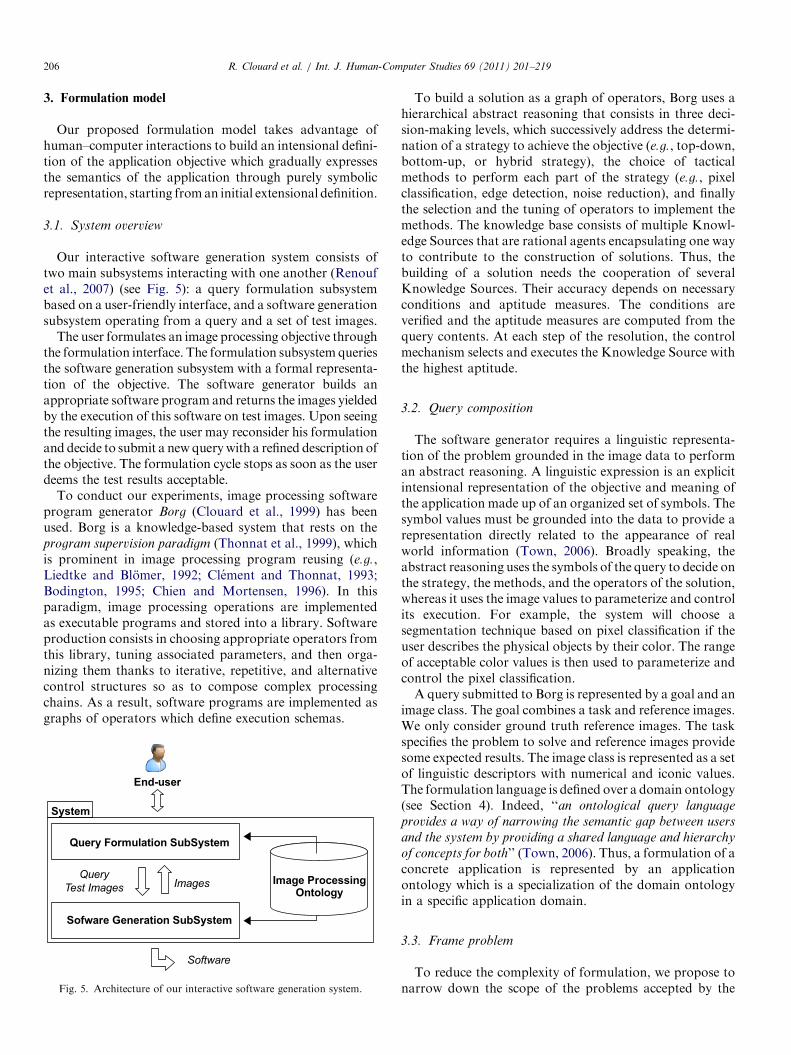
Our interactive software generation system consists oftwo main subsystems interacting with one another (Renoufet al., 2007) (see Fig. 5): a query formulation subsystembased on a user-friendly interface, and a software generationsubsystem operating from a query and a set of test images.
The user formulates an image processing objective throughthe formulation interface. The formulation subsystemqueriesthe software generation subsystem with a formal representa-tion of the objective. The software generator builds anappropriate software program and returns the images yieldedby the execution of this software on test images. Upon seeingthe resulting images, the user may reconsider his formulationand decide to submit a newquerywith a refined description ofthe objective. The formulation cycle stops as soon as the userdeems the test results acceptable.
To conduct our experiments, image processing softwareprogram generator Borg (Clouard et al., 1999) has beenused. Borg is a knowledge-based system that rests on theprogram supervision paradigm (Thonnat et al., 1999), whichis prominent in image processing program reusing (e.g.,Liedtke and Blomer, 1992; Clement and Thonnat, 1993;Bodington, 1995; Chien and Mortensen, 1996). In thisparadigm, image processing operations are implementedas executable programs and stored into a library. Softwareproduction consists in choosing appropriate operators fromthis library, tuning associated parameters, and then orga-nizing them thanks to iterative, repetitive, and alternativecontrol structures so as to compose complex processingchains. As a result, software programs are implemented asgraphs of operators which define execution schemas.
Fig. 5. Architecture of our interactive software generation system.
To build a solution as a graph of operators, Borg uses ahierarchical abstract reasoning that consists in three deci-sion-making levels, which successively address the determi-nation of a strategy to achieve the objective (e.g., top-down,bottom-up, or hybrid strategy), the choice of tacticalmethods to perform each part of the strategy (e.g., pixelclassification, edge detection, noise reduction), and finallythe selection and the tuning of operators to implement themethods. The knowledge base consists of multiple Knowl-edge Sources that are rational agents encapsulating one wayto contribute to the construction of solutions. Thus, thebuilding of a solution needs the cooperation of severalKnowledge Sources. Their accuracy depends on necessaryconditions and aptitude measures. The conditions areverified and the aptitude measures are computed from thequery contents. At each step of the resolution, the controlmechanism selects and executes the Knowledge Source withthe highest aptitude.
3.2. Query composition
The software generator requires a linguistic representa-tion of the problem grounded in the image data to performan abstract reasoning. A linguistic expression is an explicitintensional representation of the objective and meaning ofthe application made up of an organized set of symbols. Thesymbol values must be grounded into the data to provide arepresentation directly related to the appearance of realworld information (Town, 2006). Broadly speaking, theabstract reasoning uses the symbols of the query to decide onthe strategy, the methods, and the operators of the solution,whereas it uses the image values to parameterize and controlits execution. For example, the system will choose asegmentation technique based on pixel classification if theuser describes the physical objects by their color. The rangeof acceptable color values is then used to parameterize andcontrol the pixel classification.A query submitted to Borg is represented by a goal and an
image class. The goal combines a task and reference images.We only consider ground truth reference images. The taskspecifies the problem to solve and reference images providesome expected results. The image class is represented as a setof linguistic descriptors with numerical and iconic values.The formulation language is defined over a domain ontology(see Section 4). Indeed, ‘‘an ontological query language
provides a way of narrowing the semantic gap between users
and the system by providing a shared language and hierarchy
of concepts for both’’ (Town, 2006). Thus, a formulation of aconcrete application is represented by an applicationontology which is a specialization of the domain ontologyin a specific application domain.
3.3. Frame problem
To reduce the complexity of formulation, we propose tonarrow down the scope of the problems accepted by the

R. Clouard et al. / Int. J. Human-Computer Studies 69 (2011) 201–219 207
system to a unique task. This avoids dealing with the frame
problem.Real-world image processing problems often involve
more than one of the tasks identified in Definition 1. Thesetasks are chosen and organized sequentially by the users,regarding their practice of image content analysis. Forinstance, for the serous application, the cytotechnologistconsidered that the complete localization of the serous cellsrequired a sequence of four tasks:
1.
‘‘Illumination correction’’, to compensate the heteroge-neity of the illumination on the slide;2.
‘‘Detection of serous cell nuclei’’, to stop the processingprogram if there is no cell on the slide;3.
‘‘Elimination of red blood corpuscles’’, to remove distract-ing objects that hinder the localization of the cell nucleusboundary;4.
‘‘Extraction of serous cell nuclei’’, to localize the serouscell nucleus.A sequence of several tasks forces the system to update theimage class definition after each task completion, beforeperforming the following tasks. The frame problem ariseswhen the system has to describe the effects of processingoperations on the initial image class definition. For example,the task ‘‘Illumination correction’’ may affect the colorappearance of red blood corpuscles and thusmay change thedefinition of the image class for the next task ‘‘Red bloodcorpuscles elimination’’. Unfortunately, the determinationof the effects of image processing operations on images isknown to be a very difficult – may be impossible – task. Toavoid the frame problem, each task is considered separatelyand therefore users have to provide one definition of theimage class for each task.
3.4. From extensional to intensional problem representation
Even reduced to one task, a linguistic intensional repre-sentation of the problem grounded in the image data is stilldifficult to provide. To help users, the linguistic definition ofthe image class is initiated by an extensional definition.
3.4.1. Formulation by extension
An extensional definition of an image class has thetwofold advantage of being pretty easy to provide byend-users and offering a solution to the symbol anchoringproblem. The extensional definition of an image class usesblobs and entire images to describe objects of interest (e.g.,serous cell nucleus) and image characteristics (e.g., theillumination model of a scene). Users build extensionaldefinition through suitable graphical interfaces.
3.4.2. Formulation by intension
The intensional definition is built using feature extractionfor each concept or characteristic described with blobs andimages in the extensional definition. For example, if the userdefines the concept of ‘‘serous cell nucleus’’ as a region and
describes it with blobs, the system will automaticallycompute all region features such as colorimetry, photo-metry, morphology, size and so forth. The variability of the‘‘serous cell nucleus’’ region appearance in the blobs iscaptured by numerical intervals of extreme values. Theintensional formulation is thus a set of symbolic descriptorswith numerical or linguistic values.
3.5. Emergent semantics
Not all the descriptors defined by the domain ontology arenecessarily relevant for all applications. Because the systemhas no a priori knowledge about the problem, it computesvalues for all the descriptors defined by the ontology. Butsome descriptors do not make sense for a given application.For example, the object of interest ‘‘serous cell nucleus’’ isdescribed, among others, by orientation descriptors after theautomatic feature extraction. But the cytotechnologistknows that the orientation is not an intrinsic property ofthe nucleus appearance.Thus, in a second phase, the system invites the users to
build the semantics of the application by ruling out thedescriptors they deem irrelevant in the initial definition.Obviously, this task needs that the users have imageprocessing skills. But even for skill users, it remains difficult.The difficulty stems from the fact that users have no access tothe interpretation of the descriptors, and thus to the waythey are used by the software generation system to constructa solution. This is the so-called symbol grounding problem
(Harnard, 1990), which is defined as the problem of how toget access to the meaning of a symbolic system. In oursystem, the interpretation of the ontology symbols isassigned by the knowledge engineer who is responsiblefor the knowledge base content of the software generator.
3.5.1. Construction of the emergent semantics
To cope with the symbol grounding problem, we proposeto take advantage of the interaction between human andcomputer so as to construct the semantics of the problemfrom the ontology symbols. This approach considers that‘‘semantics is an emergent property of the interaction between
the user and the system’’ (Santini et al., 2001). Emergentsemantics expresses semantics through purely syntacticrepresentation and thus ‘‘the semantic understanding is the
process of understanding one domain (application domain) in
terms of another (image processing domain)’’ (Rapaport,2003). This implies that the human–computer interactionhas to be done within an environment created and config-ured by the interaction activity itself. Users learn theinterpretation assigned to the ontology symbols throughtheir impact on the results yielded by the generated software.Borg learns the confidence placed in each feature by the user.For instance, the ‘‘serous cell nucleus’’ object should bepertinently characterized by region and edge descriptors.But the cytotechnologist knows that sometimes, nucleusboundariesmay bemissed and thereby, edge features are lesscredible than region features for designing the solution.

Fig. 6. Relations between main classes of the Image Processing Ontology.
R. Clouard et al. / Int. J. Human-Computer Studies 69 (2011) 201–219208
3.5.2. Interaction cycle
The interaction cycle carries out reformulation whichconsists, for the users, in ruling out from the querydescriptors that are deemed irrelevant, and then penalizingand favoring the selected descriptors, and for Borg, inmaintaining a list of relative confidences for features andin constructing a software program. This cycle relies on astrong hypothesis: the software generator always producesan acceptable solution regarding the query contents. There isno reconsideration of the solution generated by the softwaregenerator. Therefore, the only cause of unsatisfactory resultscomes from the query contents; that is bad descriptorselection or wrong appraisals of descriptor confidences.
To assist users in performing their reformulation, not onlya list of images resulting from the execution of the softwareare returned from the software generator, but also a list ofdescriptors used to design the solution as well as a list of thedescriptors it would have liked to use. These features can beexploited by the users tomeasure the degree of responsibilityof each descriptor towards the failure of the solution, andthereby to facilitate reformulation.
As a consequence of this emergent semantics approach,the generated software is not the result of the last formula-tion, but the result of the series of formulations donethrough the interaction, because during the formulationprocess, the system has also learnt the relative confidence ineach descriptor.
1http://www.greyc.ensicaen.fr/�regis/Pantheon/resources/ImageProces
singOntology.owl
4. Image processing ontology
A domain ontology is used to provide a formal andcomputational representation of goal and data semantics.We have chosen to develop our owndomain ontology (Renoufet al., 2007) because we have considered that existingontologies (e.g., Hunter, 2001; Nouvel, 2002; Jeon et al.,
2003; Tsinaraki et al., 2005; Bloehdorn et al., 2005; Town,2006;Maillot andThonnat, 2008;Gurevich et al., 2009) are notcomplete enough to take into account all image processingobjectives and all application domains. Indeed, these ontolo-gies are meant for video or image annotation, retrieval, orunderstanding purposes. Therefore, none of them can be usedfor reconstruction and restoration objectives, most of them donot consider relationships between concepts, and none of themcover all acquisition effects.Our ontology1 represents queries by triplets: /G;C; IS,
where G is the goal specification, C is the image classdefinition, and I is a set of test images that is used to assessthe program. It is expressed in OWL DL. The concepts ofimage processing are implemented as 297 classes, therelations as 26 object properties and 16 datatype properties,and the axioms as 192 restrictions. The main classes of theontology are presented in Fig. 6.
4.1. The phenomenological hypothesis
The ontology model relies entirely on the phenomenolo-
gical hypothesis (Renouf et al., 2007). This hypothesis statesthat only information that has a visual manifestation inimages is necessary and sufficient to develop concrete imageprocessing applications. This hypothesis has two conse-quences. The benefit is to allow the construction of anontology that covers all application domains, since thevocabulary is limited to image processing concepts, andsince it is not necessary to represent domain-specific knowl-edge. For example, from a phenomenological point of view,the object ‘‘red blood corpuscle’’ can be simply representedas a small oblong red region. The drawback is that it may be

R. Clouard et al. / Int. J. Human-Computer Studies 69 (2011) 201–219 209
necessary to distinguish as many denotations of a real objectas there are distinct appearances of this object in images.
Obviously, it is a simplifying hypothesis. Some complexapplications need deep knowledge about the physics of theobserved phenomenon to decide on the processing opera-tions. Typical examples are applications where the signal-to-noise ratio is very low and relevant information is notdirectly visible in images. Such special cases are not takeninto account in our approach.
4.2. Image class definition
The image class part of the ontology distinguishes threedefinition levels: the physical, perceptive, and semanticlevels. The physical level aims to help users bridge thesensory gap, whereas the perceptive and semantic levels aimto help users bridge the semantic gap.
4.2.1. Physical concepts
The physical level is the level of the measured signal. Theclass Physical-Level references description elements ofall sources of signal degradation caused by acquisitionchains. It is defined with the property hasDefinitionElement
which takes its values from the subclasses of the classAcquisitionEffect: ImageColorimetry, Image-Photometry, ImageGeometry, ImageStorage,ImageSampling, ImageQuantization, ImageIllu-mination, Blur, and Noise. Each subclass definesits own list of suitable descriptors using the propertyhasDescriptor. For example, ImageIlluminationdefects are characterized by the following descriptors:TemporalCondition, SpatialCondition, Defect-Type, DarkImage, and Model.
Table 1 presents an example of an image class definition atthe physical level for the serous application. This definition is
Table 1
Definition of the serous application at the physical level.
Acquisition effect subclass hasDescriptor
ImageIllumination TemporalCondition = stable
SpatialCondition = heterogeneous
Model =
ImageColorimetry Colorspace = RGB
ImageQuantization BitsPerPixel = 24
Function = linear
Noise Composition = additive
Distribution = Gaussian
PowerSpectralDensity = white
Mean = 0
StandardDeviation = low
made with instances of the acquisition effect subclasses that arelinked to instances of the descriptor subclasses by the hasDe-
scriptorproperty.Actually,ImageIllumination_1 is linkedto TemporalCondition_1, SpatialCondition_1, etc.In the same way, TemporalCondition_1 is linked tothe instance ‘‘stable’’ by the property hasSymbolicValue. Inthis definition, it should be noticed that the illumination of thescene is described as spatially heterogeneous but temporallyconstant. The illumination model is given by extension bymeans of a background image, which is the visualization of anempty field without any cellular object.
4.2.2. Semantic concepts
The semantic level is focused on the objects of interest. Thenotion of object of interest is understood from a phenom-enological standpoint, namely based on visual appearance.Hence, an object of interest does not necessarily correspondto a real object, but simply to a part of a real object, or to anaggregate of real objects, and conversely any real object willbe represented by several objects of interest if it presentsvarious different appearances.Thus, the SemanticLevel class has the hasDefinition-
Part property which takes its values from ObjectOfIn-terest instances. Users create ObjectOfInterestinstances and assign a semantics through a purely syntacticrepresentation using the hasDefinitionElement property. TheDefinitionElement subclasses allows for individualvisual characterization of the objects and description ofthe spatial relationship between them.The individual visual characterization of an object is done
from the description of visual primitives. Available visualprimitives are defined as subclasses of the class Visual-Primitive: Region, Edge, Background, PointO-fInterest, ImageArea, and PointOfCloud. Eachsubclass defines its own list of related descriptors usingthe property hasDescriptor. For example, the Region classhas the descriptors: ColorHue, Orientation, Boun-daryNature, Convexity, etc. Among the existing for-mal spatial relations (Retz-Schmidt, 1988), only theTopologicalSpatialRelation (e.g., RCC-8 in 2D)and ExtrinsicSpatialRelation (e.g., Above,RightOf, InFrontOf) are included in the ontology,because, as far as we know, these are the only spatialrelations used in image processing algorithms.Table 2 gives an example of the individual definition of the
object ‘‘serous cell nucleus’’. In this definition, the object isdescribed as a region characterized by its color and itsboundary. Practically,Serouscell nucleus is a subclassof theObjectOfInterest class. It is linked to the instanceRegion_1 by the hasDefinitionElement property, and theinstance Region_1 is linked to the instance ColorHue_1by the hasDescriptor property. The relationships between thevarious objects of interest are described in Fig. 8.
4.2.3. Perceptive concepts
The perceptive level is concerned with the visual renderingof the image contents without reference to objects of interest.

Table 3
Description of the serous application at the perceptive level with instances
of visual primitive subclasses.
Visual primitive subclass hasDescriptor
Background PhotometryBrightness = the most
TextureType = no-texture
Region RegionShapeType = ellipsoid
BoundingBoxWidth = [8, 35] pixels
BoundaryNature = edge
Edge EdgeProfile = step
EdgeContrast = high
Table 4
Specification of the ‘‘extract {serous cell nucleus}’’ objective.
Task ObjectExtraction {serous cell nucleus}
Optimization criterion Maximize hits
Table 2
Visual definition of the serous cell nucleus at the semantic level.
Object of
interest
hasDefinition
Element
hasDescriptor
Cell
nucleus
Region ColorHue = [9p=8, 3p=2] radians
ShapeType = ellipsoid
BoundingBoxWidth = [8, 35] pixels
BoundaryNature = edge
Edge Profile = step
Contrast = high
R. Clouard et al. / Int. J. Human-Computer Studies 69 (2011) 201–219210
This level is genuinely useful when objects of interest do notexist, or when they are unpredictable or indescribable. Forexample, in case of robotics or image retrieval applications,objects are generally unknown beforehand. The image classis thus described at the perceptive level by homogeneousregions, background, points of interest, or edges. But whenobjects of interest are all well-known, it is more informativeto describe the scene at the semantic level.
A definition at the perceptive level corresponds to a global‘‘syntactic’’ denotation of the image contents. It is alsocomposed from the VisualPrimitive subclasses. Thedifference with the semantic definition is that each visualprimitive is described globally: users describe the varioustypes of Region, Edge, etc. that have to be considered.
Table 3 shows an example of the image class definition atthe perceptive level for the serous application. The imageclass is definedwith instances of the visual primitives: region,edge, and background.
4.2.4. Descriptor values
The descriptor values must allow for extensional andintensional definitions. To this end, the model combinesdescriptors with numerical and symbolic values for theintensional definition, and descriptors with iconic values forthe extensional definition:
(acceptable error) (prefer false alarm to miss)
Maximize boundary localization
(prefer boundary inside the region)
� Detail Level Separate just touching(acceptable error) (prefer no separation)
Numerical values are single values, interval of values, setof values, vector, andmatrix of values (e.g., a geometricaldistortion matrix).
Performance criterion Running-time r 2 s
� Quality criterion Ability = reliabilitySymbolic values are conventional terms (e.g., RGBcolor space, Gaussian noise), qualitative terms (e.g.,
high, very-low), and superlative terms (e.g., the-least, the-most), which allow to express things like ‘‘cell nucleus hasa very low size’’ or ‘‘cell nucleus has the most area’’.
� Iconic values are represented by entire image or blob filenames (e.g., Illumination model).
4.3. Goal specification
The Goal class is described by the following threeproperties:
�
hasTask identifies the current Task to perform; � hasControlConstraint takes its values from the elementsof the ControlConstraint class.
� hasReferenceImage is a list of /TestImage, Refer-enceImage S pairs.Table 4 describes the ‘‘ObjectExtraction {serous cellnucleus}’’ objective of the serous cytology application.
4.3.1. Task concepts
Available tasks are subclasses of the Task class, such as:ColorEnhancement, EdgeDetection, ObjectEx-traction, ObjectDetection, ImageDenoising,ImageSegmentation, etc. They are described by thefollowing properties:
�
hasArgument specifies the object of interest to which thetask is applied if any (e.g., ‘‘ObjectExtraction{serous cell nucleus}’’). � hasDetailLevel is used to refine the scope of the task.Examples ofDetailLevel subclasses are ‘‘do not affectthe original color rank’’, ‘‘separate just touchingobjects’’, or ‘‘separate all objects’’.
� hasOptimizationCriterion is used to set the focus ofattention of the task. Examples of Optimization-Criterion subclasses are ‘‘maximize boundary locali-zation’’ or ‘‘maximize detection hits’’.
Each subclass defines its own restrictions on the range of theproperties. For example, the ObjectDetection task hasthe following detail levels: Separation, NoSeparation,

R. Clouard et al. / Int. J. Human-Computer Studies 69 (2011) 201–219 211
AllOccurrences, AtLeastOneOccurrence, Boun-daryInside, BoundaryOutside, and SubPixel-PrecisionLocalization.
In order to reach a compromise in case of doubt aboutcompliance with constraints, each criterion to be optimizedand each level of detail constraint can be associated with anAcceptableError by the hasAcceptableError property.For example, if there is a doubt about the fact that twoobjects are overlapping or just touching, an acceptable errorfor the ‘‘separate just touching objects’’ constraint mayindicate a preference for the ‘‘separation’’ or the ‘‘noseparation’’ of the related regions.
4.3.2. Control constraint concepts
The ControlConstraint class defines two types ofconstraints:
�
The PerformanceCriterion class specifies proces-sing time limits. � The QualityCriterion class expresses requirementson the ability of the system to perform the task accordingto the specified and unspecified conditions. The twoavailable ability values are reliability (i.e., prefer no resultto bad result), and robustness (i.e., prefer bad result to noresult at all).
5. Human–computer interaction model
In the previous sections, the kind of information required todevelop image processing applications has been identified, and adomain ontology to represent them was proposed. This sectiondeals with the ways and means to help users formulateapplication ontologies that correspond to concrete applications.The interaction between the users and the system takes placethrough a user interface that organizes the formulation cycle.
The interface is written in Java using Swing as the UItoolkit, and the ontology is handled thanks to theOWLAPI.
5.1. Formulation cycle
The formulation cycle is split up into five iterative stepsderived from the formulation model exposed in Section 3:
1.
The user formulates an initial representation of theobjective, mainly extensional.2.
The system performs feature extraction from this exten-sional formulation and starts an intensional representa-tion of the objective.3.
The user discards irrelevant features from the intensionalrepresentation and adds a list of representative testimages to compose the first query.4.
Borg generates a software program and returns theimages yielded by its execution on the test images,together with the features actually used by the reasoningengine as well as features it would have liked to use.5.
In case of unsatisfactory results, the user reformulates theobjective by ruling out irrelevant features and bypenalizing or favoring feature confidences. Then, thecycle goes back to step 4 until satisfaction.
5.2. Initial extensional formulation
The formulation system provides users with five framesdedicated to:
�
the specification of the post-processing operations whichaims at specifying the context of use of the futuresoftware; � the definition of the image class at the physical level; � the definition of the image class at the semantic level orat the perceptive level if the notion of object of interestdoes not make sense;
� the specification of the task with related constraints andthe input of a set of reference images (when possible);
� and the determination of control constraints.5.2.1. Specification of the post-processing operations
Post-processing refers to operations that will be performedon the results yielded by the image processing application.Post-processing information plays no direct part in the imageprocessing formulation, but its purpose is to provideassistance later, during the task specification (see Section5.2.5). To specify post-processing operations, the interfacedisplays a panel with 11 different post-processing categories:classification, image comparison, quantification, patternrecognition, registration, scene reconstruction, detection-tracking, art visualization, visual inquiry, transmission, andarchival storage. For each post-processing category, userscan select operations among a predefined list (e.g., counting,printing, displaying, and measuring (size, position, orienta-tion, radiometry, morphology, and topology)).In the case of our running example, the ‘‘ObjectExtraction
{serous cell nucleus}’’ task is followed by a classification ofthe extracted regions in order to detect abnormal or suspectcells. This classification is based on size, morphology, andradiometry measurements.
5.2.2. Physical definition of the image class
Users select the descriptors that best account for theeffects of the acquisition chain on the visual appearance ofthe scene. All ‘‘physical descriptors’’ defined by the ImageProcessing Ontology are displayed in a panel in the form oftables (See Fig. 7). Users choose relevant descriptors andassign values with blobs or numerical values. In order tohelp users give numerical values, the system exploits adatabase that stores known descriptor values for sometraditional acquisition systems.For the ‘‘IlluminationCorrection’’ task of the cytology
example, the cytotechnologist has provided the definitiongiven in Table 1. This definition combines symbolic andiconic descriptors.

Table 5
R. Clouard et al. / Int. J. Human-Computer Studies 69 (2011) 201–219212
5.2.3. Semantic definition of the image class
If the image class can be described at the semantic level,the definition relies on the construction of a tree of objects ofinterest. Indeed, a tree helps users determine the significanceof a node according to its parent and siblings (Charlet et al.,2006). Four principles can be used to define objectsorganized in a tree: principles of similarity and differencewith parents, and principles of difference and similarity withsiblings. This allows a differential definition of the objects:the description of an object is given in terms of its similaritiesand differences with other neighboring objects.
Users identify all objects of interest that may appear onimages and organize them hierarchically by specifying thehyperonymic and meronymic relations between them:
Excerpt of the extensional definition of the serous image class at the
semantic level for the segmentation task: ‘‘ObjectExtraction {serous cell
nucleus}’’.
�Fig
com
Object of
interest
hasDefinition
Element
hasDescriptor
Cell nucleus Region
Model = y
The hyperonymic relation ‘‘kind-of’’ defines a taxonomyof objects of interest based on similarities. This structureis the basis of two elementary inferences that humansperform daily: identification, which is our ability torecognize the class of an object from its features, andspecialization/generalization, which is our ability toorganize the objects in prototypical categories.
Mucous Background PhotometryBrightness = the most (clearest)
� TextureType = noneThe meronymic relation ‘‘part-of’’ describes the compo-sition of these objects into entities and components,
Fig. 7. The part of the interface that allows users to d
. 8. A serous cytology scene viewed through microscopic slides is composed of se
posed of a nucleus surrounded by a cytoplasm. In this tree DC, EC, TPP, NT
which can then be supplemented with extrinsic, distance,and topological spatial relations.
Based on the tree, users then describe each object of interestwith relevant visual primitive descriptors using a differentialdefinition.Fig. 8 is an example of the object tree defined for the
serous application. Table 5 gives an excerpt of a possiblesemantic definition for the objects. The {Serous cell nucleus}object is described with blobs, whereas the {mucous} objectis described with linguistic values as the clearest region.
efine the physical level of the image class.
rous cells and red blood corpuscles scattered on mucous. A serous cell is
PP, and PO are the RCC-8 topological relations.

Table 7
R. Clouard et al. / Int. J. Human-Computer Studies 69 (2011) 201–219 213
5.2.4. Perceptive definition of the image class
If users choose to describe an image class at the perceptivelevel, the interface displays tables containing the symbolicdescriptors associated to each visual primitive as defined in theontology. Users can also provide several blobs for describingthe different visual appearances of what they consider as aregion, a background, a point of interest, an edge, etc.
The cytology application is described at the semantic levelbecause all objects are predictable and describable. How-ever, if we consider a hypothetical ‘‘ImagePartition’’ task,then the image class will be described at the perceptive levelwith several blobs, at least one for the each type of regions,edges and background (see Table 6).
5.2.5. Task specification
Users select the tasks to perform from a list provided bythe interface, and if needed, the related argument within thelist of the objects of interest. When possible, users shouldadd a list of reference images. These reference images arebuilt with specialized interfaces (e.g., image manipulationsoftware and interactive image segmentation system).
Then, users choose the related constraints from the listdefined in the ontology. To that aim, the system uses post-processing information provided by users at the inception ofthe formulation process, to suggest some possible con-straints and related acceptable errors. This is done by usingfirst order production rules. For example, since radiometricmeasurements are required during post-processing of the‘‘ObjectExtraction’’ task, the system proposes the boundarylocalization as an optimization criterion with a relatedacceptable error ‘‘prefer boundary inside’’ in order to avoiddistorting the measurement results with boundary pixels:
ðGoalð?xÞ4ObjectExtractionð?yÞ4hasTaskð?x; ?yÞ 4PostProcessingTaskð?zÞ4hasMeasurementð?z; radiometryÞ
-assertðBoundaryLocalizationð?wÞÞ4hasOptimizationCriterionð?x; ?wÞ 4hasAcceptableErrorð?w; prefer_boundary_insideÞÞ
5.2.6. Control constraints
Finally, users determine the type of optimization and abilityrequired for the software solution through an appropriate frame.
Table 6
Excerpt of the extensional definition of the serous image class at the
perceptive level for a hypothetical segmentation task: ‘‘ImagePartition’’.
Visual primitive
subclass
hasDescriptor
Region
Model = y
BackgroundModel = y
Edge
Model = y
5.3. First intensional formulation
Based on the initial formulation, the system builds anintensional formulation by extracting values from blobs andimages given during the initial formulation. The list ofdescriptor values that can be extracted from blobs for eachfeature is prescribed in the ontology. For example, Table 7gives an excerpt of the list of region descriptor values thatcan be extracted from the blobs given for the extensionaldefinition and presented in Table 6.Then, the formulation system invites users to correct their
initial formulation by ruling out the descriptors they deemnotrelevant to the application. For our example, we choose torule out the descriptors in italic in Table 7. As amatter of fact,serous cell nuclei are not characterized by their position,rectangularity, orientation, and number of holes. The inten-sional and the extensional definition together with test andreferences images compose the first query that is sent to Borg.
5.4. Program generation
Borg exploits the intensional definition to performabstract reasoning that supports the construction of thesoftware program. The ontology elements are used notablyto rate the knowledge source aptitude.Aptitudemeasures thedistance between the ideal knowledge source applicationcontext and the given application context. For example, theaptitude of a knowledge source that suggests using an edgedetection technique as part of the processing program isrepresented in Table 8. Each criterion is weighted with itsimportance in the aptitude rating. Borg computes theknowledge source credibility and plausibility against thecurrent intentional definition using the Dempster–Shafertheory (Shafer, 1976). Then, depending on the controlconstraints selected by the user – reliability or robustness– Borg may decide to select the knowledge source to executeat each step of the resolution process only among the credibleknowledge sources or also among the plausible ones.
Excerpt of the intensional definition of the {serous cell nucleus} concept
after the feature extraction phase.
Object of
interest
hasDefinition
Element
hasDescriptor
Ccell
nucleus
Region PhotometryBrightness = [38, 124]
PhotometryContrast = [12, 86]
ColorSaturation = [0, 0.609]
ColorHue = [3.53, 4.71] radians
Convexity = [0.4, 0.9]
Rectangularity = [0.15, 0.81]
Area = [65.56, 179.67] pixels2
BoundingBoxWidth = [8, 35] pixels
MajorAxisAngle = [0, 345] degrees
CenterOfMass = [(10, 256), (5, 245)]
NumberOfHole = 0

R. Clouard et al. / Int. J. Human-Computer Studies 69 (2011) 201–219214
5.5. Reformulation
During the reformulation process, most changes occur atthe semantic level (or at the perceptive level) of the imageclass definition. After each production of a softwareprogram, the interface displays the resulting images, thelist of descriptors used by the software generator todetermine its strategies and methods, and the descriptorsthe software generator would have liked to use. From thisinformation, users can reformulate their problem by rulingout descriptors, adding new descriptors, and increasing ordecreasing the confidence on descriptors through relateduser interfaces. When Borg receives the new query, itcomputes the new relative confidences for the descriptorsbefore constructing a fresh solution. Consider a descriptor d,the new confidence value cd is updated as follows:
�
Ta
Lis
kno
Cri
Op
No
No
Ba
Ed
Ed
Ed
+0.2, if d is marked with ‘‘+’’ by user;
� 0.2, if d is marked with ‘‘� ’’ by user (if cd o0 then cd=0); � 0, otherwise.Then, all descriptor confidences are normalized: 8d; c0d ¼cd=maxjcd j.
A value of 0.2 in the domain [0.1] corresponds to a fivepoint scale rating. It is chosen experimentally. However,Miller in his seminal article (Miller, 1956) justifies experi-mentally the use of seven point rating scales (plus or minustwo) to absolutely rate the magnitude of unidimensionalstimulus variables (e.g., auditory loudness, auditory pitch,saltiness) and thus image features.
ble 8
t of weighted criteria that defines the ideal application context of the
wledge source ‘‘Edge Detection’’.
teria Importance
timizationCriterion=BoundaryLocalization high
ise.SignalNoiseRatio Z low very-high
ise.PowerSpectralDensity=white medium
ckground.TextureType= no-texture high
ge.Contrast Z low high
ge.Profile= step high
ge.Orientation 2 {vertical, horizontal} low
Fig. 9. An example of the input imag
In our example, the ‘‘ObjectExtraction {serous cellnucleus}’’ task gives rise to different solutions dependingon the user preferences. If users give preference to edgefeatures, an edge detection process will be used to extract themarkers of the future regions followed by a watershedsegmentation to locate region boundaries. If users givepreference to region features and more particularly to colorfeatures, Borg will opt for a pixel classification based oncolor segmentation to extract the markers of the futureregions before performing the watershed segmentation.
6. Experimentations and discussion
Trying to define quantitativemeasures to evaluate the formu-lation system is tricky since the experimental results widelydepend upon the quality of the knowledge stored in the knowl-edge base of the program generation system. So, as evaluation,we propose to investigate through experiments, first, thecapacity of the system to represent different points of viewon a same application, which lead to build different softwaresolutions, second, the benefit of the interaction loop between theuser and the system tobuild customized software programs, andthird, the ability of the system to deliver effective servicesto users.
6.1. Capacity of representation
The capacity of representation is assessed by the ability ofthe language to express different definitions of a same objectivethat set forth the reasons justifying the design of variousprocessing solutions described in the literature. Prior to theexperiments, the knowledge sources and image processingoperators should be exhibited from the reverse-engineering ofthese solutions and introduced into the knowledge base.Let us take another example in the domain of aerial
imagery. The task is ‘‘ObjectExtraction {agricultural field}’’with the optimization criterion ‘‘maximize boundary loca-lization’’. Fig. 9 shows a sample of the image class with theexpected result, and Fig. 10 shows the part of the applicationontology representing the generic model of landscapescenes. For this example, we analyze four different solutionsthat give rise to two points of view on the definition of the
e (a), and the expected result (b).

Fig. 10. The part of the application ontology representing the model of landscape scene.
Table 9
A semantic definition that supports the use of the region growing approach.
Object of
interest
hasDefinition
Element
hasDescriptor
Field Region (field area) TextureType = no-texture
PhotometryContrast = [0, 27]
Rectangularity = [0.57, 1.0]
Area = [623, 120 904] pixels2
BoundaryNature = edge
Edge (field boundary) Profile = step
Contrast = [0.11, 0.27]
Sharpness = [0.82, 0.98]
Straightness = [0.7, 1.0]
Length = [143, 634] pixels
R. Clouard et al. / Int. J. Human-Computer Studies 69 (2011) 201–219 215
objective. The differences between the various definitionsare essentially located in the semantic definition of the{agricultural field} object.
6.1.1. A first point of view
The definition of the {agricultural field} object of interestis viewed by some authors (Butenuth et al., 2004; Muelleret al., 2004) as a rather homogeneous region with contrastedboundaries. They base their solution on a region growingmethod controlled by edges. For instance, Butenuth et al.propose to use a watershed segmentation controlled bythe gradient image, where the markers are the minima of thegradient image. They justify the use of this method by thefact that the field areas are rather homogeneous regions(TextureType = no texture; PhotometryContrastr low) andthe field boundaries are highly contrasted (ContrastZhigh).Mueller et al. propose to control the region growing with theedges extracted from a prior edge detection algorithm. Theyconsider that the field boundaries are well-defined, with highbrightness contrast to neighboring regions (ContrastZhigh)and relatively long and straight edges (StraightnessZhigh;LengthZmedium). For both solutions, a second step iscarried out to merge neighboring regions with low gray leveldifferences and small regions into larger ones.
Butenuth et al. perform a final third step in order to fulfillthe constraint ‘‘maximize boundary localization’’. They usethe snake algorithm. The snakes are initialized as thesmallest bounding rectangle of each extracted field sincefields are polygonal regions often with four corners(Rectangularity4medium). The external energy is the abso-lute value of the gradient since edges are contrasted(ContrastZhigh) and the internal energy is set so as tofavor rigidity because the field boundaries are described aslong straight edges (Straightness4medium; Length4 low).
6.1.2. A second point of view
The definition of the {agricultural field} object of interestis viewed by other authors (Dubuisson-Jolly and Gupta,2000; Xu et al., 2003) as a region that can be discriminatedfrom other regions by texture and color features. This newpoint of view leads to use a statistical approach based onsupervised pixel classification. Dubuisson-Jolly and Guptapropose to use maximum likelihood classification that
combines texture (TextureScale = micro; TextureType =
complex) and color information (ColorSaturation). Xu et al.opt for a SVM approach for pixel classification based onlyon texture information. Both methods use blobs to train therelated classifier (Model: blobs).
6.1.3. Definition at the semantic level
During the formulation cycle, if the user considers that{agricultural field} object is characterized by its innerhomogeneity and high contrasted boundary, he providesa semantic definition close to the one given in Table 9. If theuser provides blobs, the values are set automatically at thefeature extraction stage. The definition thus contains allthe information thatmotivates the use of a solution based ona region growing approach: the regions are non-texturedareas with a known minimum area and low photometrycontrast, and their boundaries are long straight edges.Actually, Borg chooses the Buthenuth’s solution becauseit is regarded as more stable than the second one (edgedetection is known to be an unstable process). But, if the usergives higher confidence to the edge descriptors of the sameformulation, then Borg will select the Mueller’s solution.Conversely, if the user gives preference to the regiondescriptors then Borg will choose the first one.If the user sees the {agricultural field} object as a textured
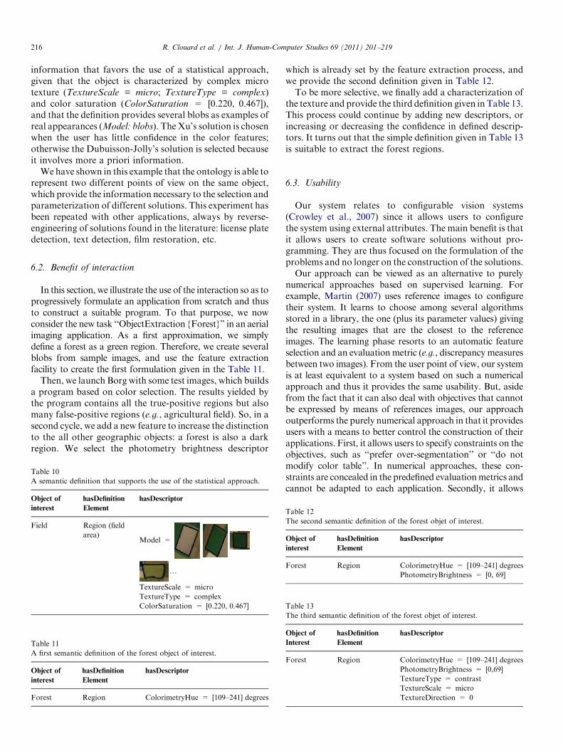
region than he provides a semantic definition such as the onein Table 10. This definition contains all necessary
R. Clouard et al. / Int. J. Human-Computer Studies 69 (2011) 201–219216
information that favors the use of a statistical approach,given that the object is characterized by complex microtexture (TextureScale = micro; TextureType = complex)and color saturation (ColorSaturation = [0.220, 0.467]),and that the definition provides several blobs as examples ofreal appearances (Model: blobs). The Xu’s solution is chosenwhen the user has little confidence in the color features;otherwise the Dubuisson-Jolly’s solution is selected becauseit involves more a priori information.
We have shown in this example that the ontology is able torepresent two different points of view on the same object,which provide the information necessary to the selection andparameterization of different solutions. This experiment hasbeen repeated with other applications, always by reverse-engineering of solutions found in the literature: license platedetection, text detection, film restoration, etc.
6.2. Benefit of interaction
In this section, we illustrate the use of the interaction so as toprogressively formulate an application from scratch and thusto construct a suitable program. To that purpose, we nowconsider the new task ‘‘ObjectExtraction {Forest}’’ in an aerialimaging application. As a first approximation, we simplydefine a forest as a green region. Therefore, we create severalblobs from sample images, and use the feature extractionfacility to create the first formulation given in the Table 11.
Then, we launch Borg with some test images, which buildsa program based on color selection. The results yielded bythe program contains all the true-positive regions but alsomany false-positive regions (e.g., agricultural field). So, in asecond cycle, we add a new feature to increase the distinctionto the all other geographic objects: a forest is also a darkregion. We select the photometry brightness descriptor
Table 10
A semantic definition that supports the use of the statistical approach.
Object of
interest
hasDefinition
Element
hasDescriptor
Field Region (field
area)Model =
y
TextureScale = micro
TextureType = complex
ColorSaturation = [0.220, 0.467]
Table 11
A first semantic definition of the forest object of interest.
Object of
interest
hasDefinition
Element
hasDescriptor
Forest Region ColorimetryHue = [109–241] degrees
which is already set by the feature extraction process, andwe provide the second definition given in Table 12.To be more selective, we finally add a characterization of
the texture and provide the third definition given in Table 13.This process could continue by adding new descriptors, orincreasing or decreasing the confidence in defined descrip-tors. It turns out that the simple definition given in Table 13is suitable to extract the forest regions.
6.3. Usability
Our system relates to configurable vision systems(Crowley et al., 2007) since it allows users to configurethe system using external attributes. The main benefit is thatit allows users to create software solutions without pro-gramming. They are thus focused on the formulation of theproblems and no longer on the construction of the solutions.Our approach can be viewed as an alternative to purely
numerical approaches based on supervised learning. Forexample, Martin (2007) uses reference images to configuretheir system. It learns to choose among several algorithmsstored in a library, the one (plus its parameter values) givingthe resulting images that are the closest to the referenceimages. The learning phase resorts to an automatic featureselection and an evaluationmetric (e.g., discrepancy measuresbetween two images). From the user point of view, our systemis at least equivalent to a system based on such a numericalapproach and thus it provides the same usability. But, asidefrom the fact that it can also deal with objectives that cannotbe expressed by means of references images, our approachoutperforms the purely numerical approach in that it providesusers with a means to better control the construction of theirapplications. First, it allows users to specify constraints on theobjectives, such as ‘‘prefer over-segmentation’’ or ‘‘do notmodify color table’’. In numerical approaches, these con-straints are concealed in the predefined evaluationmetrics andcannot be adapted to each application. Secondly, it allows
Table 12
The second semantic definition of the forest objet of interest.
Object of
interest
hasDefinition
Element
hasDescriptor
Forest Region ColorimetryHue = [109–241] degrees
PhotometryBrightness = [0, 69]
Table 13
The third semantic definition of the forest objet of interest.
Object of
Interest
hasDefinition
Element
hasDescriptor
Forest Region ColorimetryHue = [109–241] degrees
PhotometryBrightness = [0,69]
TextureType = contrast
TextureScale = micro
TextureDirection = 0
R. Clouard et al. / Int. J. Human-Computer Studies 69 (2011) 201–219 217
users to explicitly construct the semantics of their application.With purely numerical approaches, the semantics of theapplication is implicitly encoded in the references imagesand it is decoded by the system via evaluationmetrics, withoutnegotiation of meaning. Therefore, the system could selectfeatures that are not relevant for the application if thereference images are poorly chosen. With our approach,the query is the result of a negotiation of meaning betweenwhat the users want and what the system can provide.
Of course, as mentioned above, the construction of anexplicit semantics is very difficult to exhibit beforehand.However, the interaction cycle leads to build an intensionalformulation starting from an initial extensional formulation. Itmeans that the construction is not a creation from scratch but aselection process, easier to perform. Furthermore, becausequeries combineboth intensional and extensional formulations,users can adjust the level of detail they wish for the intensionalexpression. For example, the intensional part of the secondpoint of view of the aerial application is less developed than thefirst one. Notice that there is no means to guarantee that oneformulation does not contradict the other. The consequence ofinconsistencies is bad output results. Users are responsible forensuring consistency between the iconic descriptors (blobs andimages) and the symbolic descriptors as well as their values, inthe same way that they must ensure consistency between thereference images and the objective formulation.
Just for information only, the development of the foursolutions for the aerial application took one week tosupplement our image processing library with the newoperators and to create the knowledge base, and one dayto formulate the four intensional queries and thus toproduce the four software programs (most of the timewas spent at creating the blobs and reference images).
7. Conclusion
The main contribution of this paper stems from twomodels, a model of formulation and a model of interaction.They are the foundations of an interactive software gen-eration system oriented towards producing customizedsoftware for image processing applications.
7.1. The model of formulation
The model of formulation identifies and organizes piecesof information required to build image processing softwareprograms that suit users requirements. The model rests onthe following assumptions:
1.
An application is tailored for one processing goal and oneimage class. The intent is to avoid the frame problem andto reduce the variability of the input images.2.
The goal is specified as a task with constraints andoptional reference images. The task identifies the imageprocessing objective, the constraints represent the userrequirements, and the reference images give someexpected result samples.3.
The image class definition amounts to a denotation of theimage contents that comes from two of the three semioticlevels: physical and perceptive or semantic levels. Thisdenotation is done by means of extensional and inten-sional representations of the pertinent information whichaccounts for the fact that some elements of the formula-tion are advantageously described by means of an iconicvocabulary and others by means of a symbolicvocabulary.Our approach adopts a cognitivist position which givespriority to an intensional definition of the image class,because it provides an explicit representation of the seman-tics of the application. However, an extensional definition isalso required to keep a strict matching with the visualappearance of the information in images. The phenomen-ological hypothesis makes the definition of a domainontology possible, in so far as the image class definition isrestricted to a denotation based on visual features. Thisdomain ontology identifies which symbolic and iconicprimitives, must be the symbols of a formal language ableto explicitly represent the objectives and semantics of anyapplication. In this paper, we claim that if phenomenolo-gical representation is not sufficient to capture the completemeaning of an image (Santini et al., 2001), it is nonethelesssufficient to design image processing software.
7.2. The model of interaction
It is well-known that cognitivist systems suffer from thesymbol grounding problem (Vernon, 2007).We proposed totackle this issue through interaction. The model of interac-tion defines ways to compose suitable linguistic formula-tions. The first phase of the interaction aims at formulatingan intensional definition of the problem, which is difficult todo beforehand, from an extensional definition, which makesthe tasks easier. The second phase aims at constructing thesemantics of the application as an emergent process, wherethe users learn the interpretation given by the knowledgeengineer to the language symbols, and the system learns therelative confidences given by the users to their descriptionelements. Thereby, interaction provides a means to bridgethe semantic and sensory gaps. It gradually leads to anexplicit representation of the semantics of the applicationgrounded in the image data.
7.3. Future works
Extensions of this work concern, on the one hand, thereformulation and on the other hand, the automaticgeneration of evaluation rules.In the current state of the formulation system, there is still
a cognitive gap between the evaluation of the resultingimages and the correction of the query contents with newdescriptors and new descriptor confidences. The challenge isto connect the evaluation results to the formulation elementsrepresented in the query.

R. Clouard et al. / Int. J. Human-Computer Studies 69 (2011) 201–219218
Moreover, the ontology gives us a means to automaticallybuild suitable evaluation rules. The formulation languageprovides explicit representation of the purpose and thesemantics of the application from which it is possible todraw up customized supervised or unsupervised evaluationmeasures.
References
Agarwal, S., Awan, A., Roth, D., 2004. Learning to detect objects in images
via a sparse, part-based representation. IEEE Trans. Pattern Anal.
Mach. Intell. 26 (11), 1475–1490.
Bloehdorn, S., Petridis, K., Saathoff, C., Simou, N., Tzouvaras, V.,
Avrithis, Y., Handschuh, S., Kompatsiaris, S., Staab, Y., Strintzis,
M., 2005. Semantic annotation of images and videos for multimedia
analysis. In: Second European Semantic Web Conference (ESWC),
Crete, Greece, pp. 592–607.
Bodington, R., 1995. A software environment for the automatic config-
uration of inspection systems. In: International Workshop on Knowl-
edge Based Systems for the Reuse of Program Libraries (KBUP),
Sophia Antipolis, France, pp. 100–108.
Butenuth, M., Straub, B.-M., Heipke, C., 2004. Automatic extraction of
field boundaries from aerial imagery. In: KDNet Symposium on
Knowledge-Based Services for the Public Sector, Bonn, Germany,
pp. 14–25.
Camara,G., Engenhofer,M., Fonseca, F.,Monteiro,A., 2001.What’s in an
image? in: International Conference on Spatial Information Theory:
Foundations ofGeographic Information Science, vol. 2205,MorroBay,
CA, pp. 474–488.
Charlet, J., Bachimont, B., Jaulent, M.-C., 2006. Building medical
ontologies by terminology extraction from texts: an experiment for
the intensive care units. Comput. Biol. Med. 36 (7), 857–870.
Chien, S., Mortensen, H., 1996. Automating image processing for scientific
data analysis of a large image database. IEEE Trans. Pattern Anal.
Mach. Intell. 18 (8), 854–859.
Clement, V., Thonnat, M., 1993. A knowledge-based approach to integra-
tion of image procedures processing. Computer Vision Graphics and
Image Processing: Image Understanding 57 (2), 166–184.
Clouard, R., Porquet, C., Elmoataz, A., Revenu, M., 1999. Borg: a
knowledge-based system for automatic generation of image processing
programs. IEEE Trans. Pattern Anal. Mach. Intell. 21 (2), 128–144.
Coradeschi, S., Saffiotti, A., 2003. An introduction to the anchoring
problem. Robotics and Autonomous Syst. 43 (2–3), 85–96.
Crowley, J., Hall, D., Emonet, R., 2007. Autonomic computer vision
systems. In: International Conference on Computer Vision Systems
(ICVS’07), Bielefeld, Germany.
Dasiopoulou, S., Mezaris, V., Kompatsiaris, I., Papastathis, V.-K.,
Strintzis,M., 2005.Knowledge-assisted semantic video object detection.
IEEE Trans. Circuits and Syst. Video Technol. 15 (10), 1210–1224.
Draper, B., Hanson, A., Riseman, E., 1996. Knowledge-directed vision:
control, learning, and integration. Proc. IEEE 84 (11), 1625–1637.
Draper, B., Bins, J., Baek, K., 1999. ADORE: adaptive object recognition.
In: International Conference on Vision Systems, Las Palmas de Gran
Canaria, Spain, pp. 522–537.
Dubuisson-Jolly, M.-P., Gupta, A., 2000. Color and texture fusion:
application to aerial image segmentation and GIS updating. Image
and Vision Comput. 18 (10), 823–832.
Gonzalez, R.C., Woods, R.E., Digital Image Processing, third ed. Prentice-
Hall Inc, Upper Saddle River, New Jersey, 2008.
Gurevich, I.B., Savetti, O., Trusova, Y.O., 2009. Fundamental concepts
and elements of image analysis ontology. Pattern Recognition and
Image Anal. 19 (4), 603–611.
Harnard, S., 1990. The symbol grounding problem. Physica D 42 (1–3),
335–346.
Hasegawa, J.-I., Kubota,H., Toriwaki, J.-I., 1986.Automated construction
of image processing procedures by sample-figure presentation. In: 8th
International Conference on Pattern Recognition (ICPR), Paris,
France, pp. 586–588.
Hudelot, C., Atif, J., Bloch, I., 2008. Fuzzy spatial relation ontology for
image interpretation. Fuzzy Sets Syst. 159 (15), 1929–1951.
Hudelot, C., Maillot, N., Thonnat, M., 2005. Symbol grounding for
semantic image interpretation: from image data to semantics. In: IEEE
International Workshop on Semantic Knowledge in Computer Vision
(ICCV), Beijing, China, pp. 1–8.
Hunter, J., 2001. Adding multimedia to the semantic web—building an
MPEG-7 ontology. In: International Semantic Web Working Sympo-
sium (SWWS), Stanford, CA, pp. 261–281.
Jeon, J., Lavrenko, V., Manmatha, R., 2003. Automatic image annotation
and retrieval using cross-media relevance models. In: 26th International
Conference on Research and Development in Information Retrieval,
Toronto, Canada, pp. 119–126.
Lezoray, O., Cardot, H., 2000. Cooperation of color pixel classification
schemes and color watershed: a study for microscopic images. IEEE
Trans. Image Process. 11 (7), 783–789.
Leibe, B., Schiele, B., 2003. Interleaved object categorization and segmen-
tation. In: British Machine Vision Conference (BMVC), Norwich, UK,
pp. 145–161.
Levin, A., Lischinski, D., Weiss, Y., 2004. Colorization using optimization.
ACM Trans. Graphics 23 (3), 689–694.
Levner, I., Bulitko, V., Lihong, L., Lee, G., Greiner, R., 2003. Towards
automated creation of image interpretation systems. In: 16th Australian
Joint Conference on Artificial Intelligence, Perth, Australia, pp.
653–665.
Li, Q., Luo, S., Zhongzhi, S., 2007. Semantics-based art image retrieval
using linguistic variable. In: Fourth International Conference on Fuzzy
Systems and Knowledge Discovery, Haikou, China, pp. 406–410.
Liedtke, C., Blomer, A., 1992. Architecture of the knowledge based
configuration system for image analysis ‘‘Conny’’. In: IEEE Interna-
tional Conference on Pattern Recognition (ICPR), The Hague, Nether-
lands, pp. 375–378.
Maillot, N., Thonnat, M., 2008. Ontology-based complex object recogni-
tion. Image and Vision Comput. 26 (1), 102–113.
Martin, V., Maillot, N., Thonnat, M., 2006. A learning approach for
adaptive image segmentation. In: 4th IEEE International Conference on
Computer Vision Systems (ICVS), New York, pp. 40–47.
Martin, V., 2007. Cognitive vision: supervised learning for image and video
segmentation. Ph.D. Thesis, University of Nice Sophia Antipolis,
France, December.
Matsuyama, T., 1989. Expert systems for image processing: knowledge-
based composition of image analysis processes. Comput. Vision,
Graphics and Image Process. 48 (1), 22–49.
Mezaris, V., Kompatsiaris, I., Strintzis, M., 2004. Region-based image
retrieval using an object ontology and relevance feedback. J. Appl.
Signal Process. 6 (1), 886–901.
Miller, G., 1956. The magic number seven, plus or minus two: some limits
on our capacity for processing information. Psychol. Rev. 63 (2), 81–97.
Mueller, M., Segl, K., Kaufmann, H., 2004. Edge- and region-based
segmentation technique for the extraction of large, man-made objects in
high-resolution satellite imagery. Pattern Recognition 37 (8),
1619–1628.
Nouvel, A., 2002. Description de concepts par un langage visuel pour un
syst�eme d’aide �a la conception d’applications de traitement d’images.
Ph.D. Thesis, Paul Sabatier University, Toulouse, France, September.
Pratt, W.K., 2007. Digital Image Processing: PIKS Scientific Inside. Wiley-
Interscience.
Proti�ere, A., Sapiro, G., 2007. Interactive image segmentation via
adaptive weighted distances. IEEE Trans. Image Process. 16 (4),
1046–1057.
Rapaport, W., 2003. What did you mean by that? Misunderstanding,
negotiation, and syntactic semantics. Minds andMach. 13 (3), 397–427.
Renouf, A., Clouard, R., Revenu, M., 2007. A platform dedicated to
knowledge engineering for the development of image processing
applications. In: International Conference on Enterprise Information
Systems (ICEIS), Funchal, Portugal, pp. 271–276.

R. Clouard et al. / Int. J. Human-Computer Studies 69 (2011) 201–219 219
Retz-Schmidt, G., 1988. Various views on spatial prepositions. AI
Magazine 9 (1), 95–105.
Russ, J.C., 2006. The Image Processing Handbook, fifth ed. (Image
Processing Handbook), CRC Press Inc., Boca Raton, FL, USA.
Santini, S.,Gupt,A., Jain,R., 2001.Emergent semantics through interaction in
image databases. IEEE Trans. Knowl. Data Eng. 13 (3), 337–351.
Shafer, G., 1976. A Mathematical Theory of Evidence. Princeton Uni-
versity Press, Princeton, NJ.
Smeulders, A.,Worring,M., Santini, S., Gupta, A., Jain, R., 2000. Content-
based image retrieval at the end of the early years. IEEE Trans. Pattern
Anal. Mach. Intell. 22 (12), 1349–1380.
Thonnat, M., Moisan, S., Crubezy, M., 1999. Experience in integrating image
processing programs. In: H. Christensen (Ed.), International Conference
on Vision Systems (ICVS), Lecture Notes in Computer Science, Springer-
Verlag, Las Palmas, Gran Canaria, Spain, 1999, pp. 200–215.
Town, C., 2006. Ontological inference for image and video analysis. Mach.
Vision Appl. 17 (2), 94–115.
Tsinaraki, C., Polydoros, P., Kazasis, F., Christodoulakis, S., 2005.
Ontology-based semantic indexing for MPEG-7 and TV-anytime
audiovisual content. Multimedia Tools Appl. 26 (3), 299–325.
Udupa, J.K., 1982. Interactive segmentation and boundary surface
formation. Comput. Graphics Image Process. 18 (1), 213–235.
Vernon, D., 2007. Cognitive vision: the case for embodied perception.
Image and Vision Comput. 26 (1), 127–140.
Xu, F., Li, X., Yan, Q., 2003. Aerial images segmentation based on SVM.
In: International Conference on Machine Learning and Cybernetics,
vol. 4, Wuhan, China, pp. 2207–2211.
Zhou,X.-R., Shimizu,A.,Hasegawa, J., Toriwaki, J.,Hara, T., Fujita,H., 2001.
Vision expert system 3D-IMPRESS for automated construction of three
dimensional image processing procedures. In: Seventh International Con-
ference on Virtual Systems and Multimedia, Berkeley, CA, pp. 527–536.
Zou, J., Nagy, G., 2006. Human–computer interaction for complex pattern
recognition problems. In: Ho, T.K., Basu, M., (Eds.), Data Complexity
in Pattern Recognition, Springer, London, pp. 271–286.
Recommended