Fuel Manager – MKII
Installation & Specification Manual
Manual Number 9000-006, Revision B

NBCS Fuel Manager Leader in Automated Controls
NBCS Inc. 12/8/2000 - 2 - Confidential
NBCS
Automated Fuel Management Systems
Introduction, Installation, and
Trouble Shooting
Manual
For:
The Fuel Manager Island Control Unit (ICU)
(RF/ID Option)
eFueling Division of National Business Control Systems 8708 West Royal Lane
Irving, Texas 75063
Phone: (972) 929-5151 Fax: (972) 929-4443
(FM_InstallManual_RF_12082000a)
NBCS Fuel Manager Leader in Automated Controls
NBCS Inc. 12/8/2000 - 3 - Confidential
TABLE OF CONTENTS
1. THE FUEL MANAGER INTRODUCTION ............................................................................ 3
2. SYSTEM OVERVIEW AND THE FUELING TRANSACTION PROCESS………………………..4
3. FUEL MANAGER SYSTEM HARDWARE ........................................................................... 5
3.1. DISPLAY....................................................................................................................... 5 3.2. KEYPAD........................................................................................................................ 5 3.3. MAGNETIC STRIPE CARD READER .................................................................................... 5 3.4. FRONT PANEL EXTENDER (FPE)....................................................................................... 5 3.5. MK2 MICROPROCESSOR BOARD ..................................................................................... 5 3.6. DISPENSER CONTROL MODULE (DCM) ............................................................................. 6 3.7. SOLID STATE RELAY BOARD............................................................................................ 6 3.8. ICU POWER SUPPLY ..................................................................................................... 6 3.9. ICU ENCLOSURE........................................................................................................... 6 3.10. RADIO FREQUENCY MULTIPLEXOR (RF MUX) ................................................................... 6
4. FUEL MANAGER ISLAND CONTROL UNIT (ICU) LAYOUT................................................ 7
4.1. ISLAND CONTROL UNIT LAYOUT - DETAILED, BOARD LEVEL INTEGRATED V IEW........................ 7 4.2. FUEL MANAGER ICU CABLE AND W IRING ASSEMBLIES ........................................................ 8 4.3 MK2 MICROPROCESSOR BOARD ..................................................................................... 9 4.4 MK2 MICROPROCESSOR BOARD'S RS-232 COMMUNICATIONS ...........................................10 4.5 FRONT PANEL EXTENDER BOARD (FPE) .........................................................................11 4.6 DISPENSER CONTROL MODULE (DCM) ...........................................................................12 4.7 SOLID STATE RELAY BOARD..........................................................................................13 4.8 NEW STYLE POWER SUPPLY BOARD...............................................................................14
5. FUEL MANAGER INSTALLATION SECTTION (SITE DIAGRAMS).....................................15
5.1 EXAMPLE CONDUIT LAYOUT #1- BUILDING BASED, MECH DISPENSERS .................................16 5.2 EXAMPLE CONDUIT LAYOUT #2 - ISLAND BASED, MECH. DISPENSERS ..................................17 5.3 EXAMPLE CONDUIT LAYOUT #3 - BUILDING BASED, MECH. DISPENSERS -RF/AVID................18 5.4 ICU WIRING SPECIFICATIONS .........................................................................................19 5.5 OVERALL SITE WIRING DIAGRAM.....................................................................................20 5.6 EXPLANATION OF THE ICU'S PUMP CONTROL PROCESS .....................................................21
6. FUEL MANAGER TROUBLE SHOOTING SECTTION .......................................................22
6.1 GENERAL / DISPLAY SYMPTOMS TROUBLE SHOOTING SECTION ...........................................23 6.2 RS-232 COMMUNICATIONS TROUBLE SHOOTING SECTION ..................................................24 6.3 DETAILED DIRECT RS-232 COMMUNICATIONS TROUBLE SHOOTING .................................25 6.4 DISPENSER / PUMP INTERFACE TROUBLE SHOOTING SECTION.............................................26

NBCS Fuel Manager Leader in Automated Controls
NBCS Inc. 12/8/2000 - 4 - Confidential
1. Fuel Manager Introduction
The NBCS Fuel Manager is a reliable stand-alone automated fuel management system (FMS) that
has evolved from over ten (10) years of reliable field service. The Fuel Manager terminal is the
central component at the unattended vehicle-fueling site. It is capable of accepting user information
on vehicles and/or drivers from: keypad entry, proximity keys, magnetic stripe cards, and/or from
RF/ID devices such as passive RF tags and Vehicle Data Modules (VDM) both based on Texas
Instruments TIRIS technology.
The base island terminal is capable of controlling up to 8 hoses. Expansion capability is available
for up to 16 hoses. In addition to host communication, each terminal has three (3) RS-232 ports that
can be used to interface with other fuel site equipment such as tank monitors and optional
transaction logging printers. The user interface consists of an easily read backlit LCD display, an ID
device reader if required, and an environmentally sealed keypad. Receipt printers are available for
retail applications.
The Fuel Manager is weatherproof (NEMA 3R enclosure rating), tamper-resistant, and reasonably
protected from vandalism due to its very robust construction. The enclosure consists of an inner
housing that is powder-coated steel with a weather seal between it and the powder coated aluminum
front panel assembly. A stainless steel skin provides protections over the exposed surfaces of the
enclosure and distinctive styling. Each terminal has a built in thermostatically controlled heater. The
terminal can withstand a temperature range from -40° F to 167° F in any humidity condition.
Configurations:
The system can be configured to operate as a standalone device that, once configured from the
FMS host computer, verifies the users against its local database, and then is able to authorize up to
sixteen fuel dispensers simultaneously after which is captures and stores the transactions for
retrieval by the host. The system can also be configured to operate in the eFueling Network or eFN
mode whenever TCP/IP network communications are available. In the eFN mode the Fuel Manager
maintains a constant network connection to host eFN server PC that enables it to verify user
information against the centrally located database. Once transactions are captured the ICU
automatically sends the transactions into the eFN server.
NBCS Fuel Manager Leader in Automated Controls
NBCS Inc. 12/8/2000 - 5 - Confidential
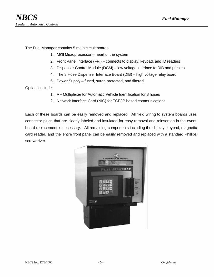
The Fuel Manager contains 5 main circuit boards:
1. MKII Microprocessor – heart of the system
2. Front Panel Interface (FPI) – connects to display, keypad, and ID readers
3. Dispenser Control Module (DCM) – low voltage interface to DIB and pulsers
4. The 8 Hose Dispenser Interface Board (DIB) – high voltage relay board
5. Power Supply – fused, surge protected, and filtered
Options include:
1. RF Multiplexer for Automatic Vehicle Identification for 8 hoses
2. Network Interface Card (NIC) for TCP/IP based communications
Each of these boards can be easily removed and replaced. All field wiring to system boards uses
connector plugs that are clearly labeled and insulated for easy removal and reinsertion in the event
board replacement is necessary. All remaining components including the display, keypad, magnetic
card reader, and the entire front panel can be easily removed and replaced with a standard Phillips
screwdriver.
NBCS Fuel Manager Leader in Automated Controls
NBCS Inc. 12/8/2000 - 6 - Confidential
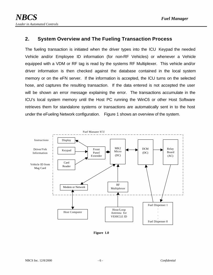
2. System Overview and The Fueling Transaction Process The fueling transaction is initiated when the driver types into the ICU Keypad the needed
Vehicle and/or Employee ID information (for non-RF Vehicles) or whenever a Vehicle
equipped with a VDM or RF tag is read by the systems RF Multiplexer. This vehicle and/or
driver information is then checked against the database contained in the local system
memory or on the eFN server. If the information is accepted, the ICU turns on the selected
hose, and captures the resulting transaction. If the data entered is not accepted the user
will be shown an error message explaining the error. The transactions accumulate in the
ICU’s local system memory until the Host PC running the WinC6 or other Host Software
retrieves them for standalone systems or transactions are automatically sent in to the host
under the eFueling Network configuration. Figure 1 shows an overview of the system.
Display
Keypad Front Panel
Extender
Modem or Network
Fuel Manager ICU
Host Computer
Fuel Dispenser 1 . . . .
Fuel Dispenser 8
Figure 1.0
Instructions
Vehicle ID from Mag Card
Driver/Veh Information
MK2 Micro (DC)
DCM (DC)
Relay Board (AC)
Hose/Loop Antenna for VEHICLE ID
RF Multiplexor
Card Reader
NBCS Fuel Manager Leader in Automated Controls
NBCS Inc. 12/8/2000 - 7 - Confidential
3. Fuel Manager System Hardware
3.1 Display- The Fuel Manager uses an easy to read high contrast LCD display to relay instruction to the user.
It can withstand temperature variations from sub-zero to extreme heat.
3.2 Keypad – The Button type keypad is environmentally sealed and has been proven reliable for years of
constant use. The keypad consists of 16 keys, 12 Number keys and 4 Function keys. The Function keys
are: CLEAR, REV, MENU, and ENTER. The CLEAR key allows the user to clear the current entry or
reset back to the first prompt. The REV key allows a technician/user to enter the Hose Watch mode.
Hose Watch is a diagnostic screen that shows the pulser totalizer, handle signal, and whether or not the
hose is authorized. The MENU key allows the user to access the Read ChipKey, Write ChipKey
(password protected), and the diagnostic functions Hose Watch and RF Watch. The ENTER key is
pressed after each entry of information and tells the MK2 Microprocessor board that the user is finished
entering data and is ready for the next step.
3.3 Card Reader – The Fuel Manager’s magnetic stripe card reader is an externally mounted swipe type. It is
resistant to inclement weather and airborne debris. Periodic cleanings are the only required maintenance,
as swipe-type readers have no moving parts to wear out. Cleaning the swipe reader can be
accomplished using off the shelf card reader cleaning kits or by simply passing an alcohol soaked folded
paper towel through the card pathway. Extreme ice and snow conditions may require the optional card
reader cover.
3.4 Front Panel Extender (FPE) – The ICU front panel mounted FPE board is the MK2 Microprocessor
board’s interface and connection center for the keypad, display, and other front panel mounted periphrial
components.
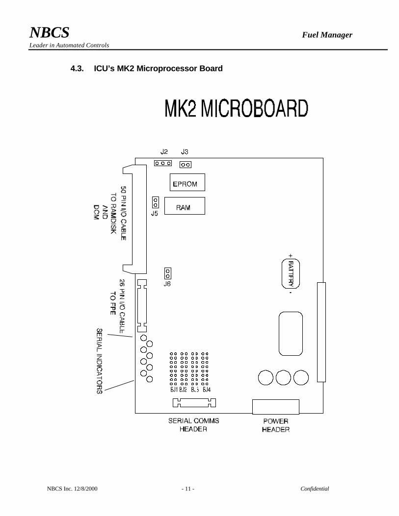
3.5 MK2 Microprocessor Board – The rear mounted board is the brains of the Fuel Manager Island Control
Unit. It connects to and controls all peripherals (keypad, cardreader, display, DCM, Relay Board, and
modem). The MK2 board uses a Zilog Z-80 based microprocessor system, and has lithium battery
backed up RAM, four RS-232 serial ports. It utilizes low power, solid state technology that offers years of
error free operation.
NBCS Fuel Manager Leader in Automated Controls
NBCS Inc. 12/8/2000 - 8 - Confidential
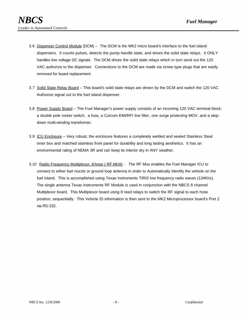
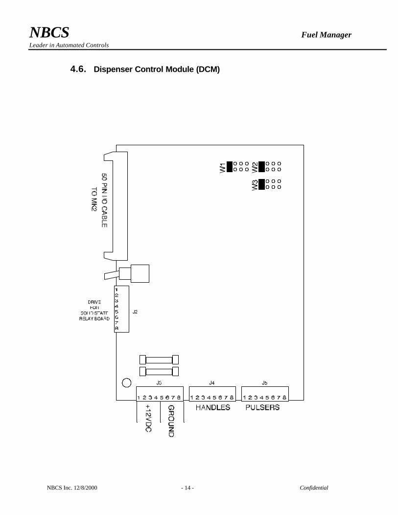
3.6 Dispenser Control Module (DCM) – The DCM is the MK2 micro board’s interface to the fuel island
dispensers. It counts pulses, detects the pump handle state, and drives the solid state relays. It ONLY
handles low voltage DC signals. The DCM drives the solid state relays which in turn send out the 120
VAC authorize to the dispenser. Connections to the DCM are made via screw type plugs that are easily
removed for board replacement.
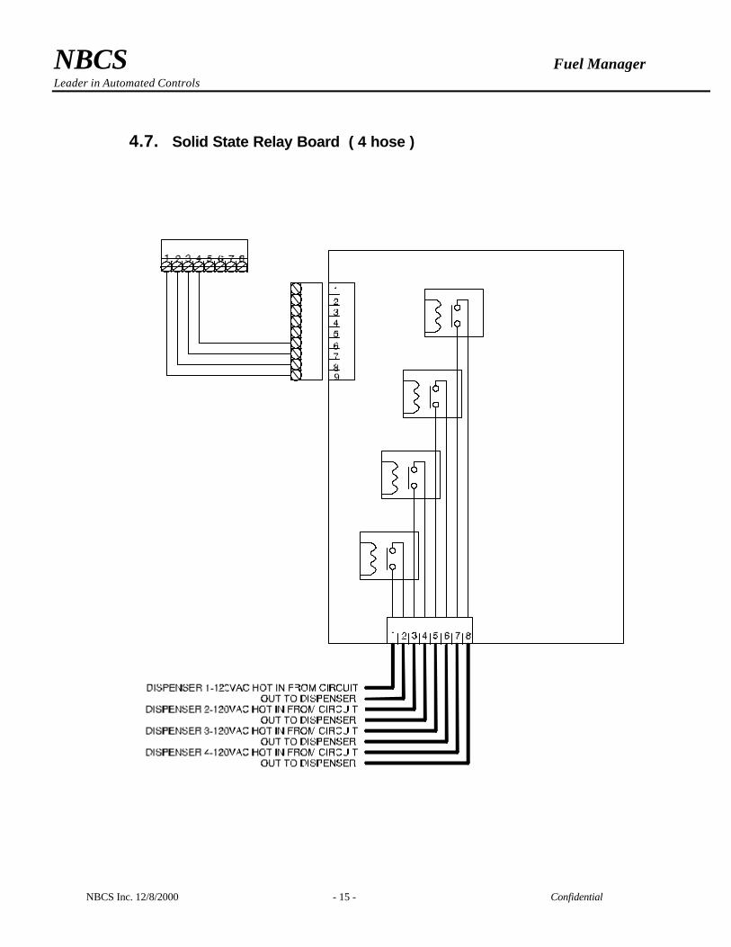
3.7 Solid State Relay Board – This board’s solid state relays are driven by the DCM and switch the 120 VAC
Authorize signal out to the fuel island dispenser.
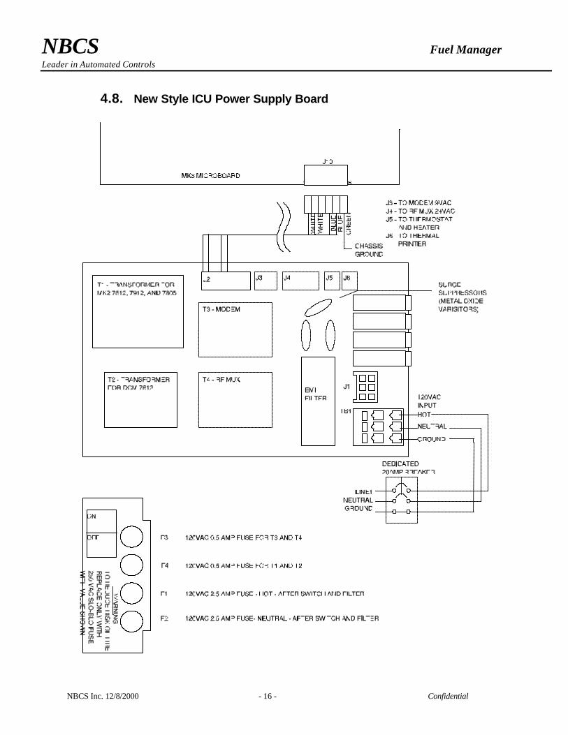
3.8 Power Supply Board – The Fuel Manager’s power supply consists of an incoming 120 VAC terminal block,
a double pole rocker switch, a fuse, a Corcom EMI/RFI line filter, one surge protecting MOV, and a step-
down multi-winding transformer.
3.9 ICU Enclosure – Very robust, the enclosure features a completely welded and sealed Stainless Steal
inner box and matched stainless front panel for durability and long lasting aesthetics. It has an
environmental rating of NEMA 3R and can keep its interior dry in ANY weather.
3.10 Radio Frequency Multiplexor, 8-hose ( RF-MUX) - The RF Mux enables the Fuel Manager ICU to
connect to either fuel nozzle or ground loop antenna in order to Automatically Identify the vehicle on the
fuel Island. This is accomplished using Texas Instruments TIRIS low frequency radio waves (134Khz).
The single antenna Texas Instruments RF Module is used in conjunction with the NBCS 8 channel
Multiplexor board. This Multiplexor board using 8 reed relays to switch the RF signal to each hose
position, sequentially. This Vehicle ID information is then sent to the MK2 Microprocessor board’s Port 2
via RS-232.
NBCS Fuel Manager Leader in Automated Controls
NBCS Inc. 12/8/2000 - 9 - Confidential
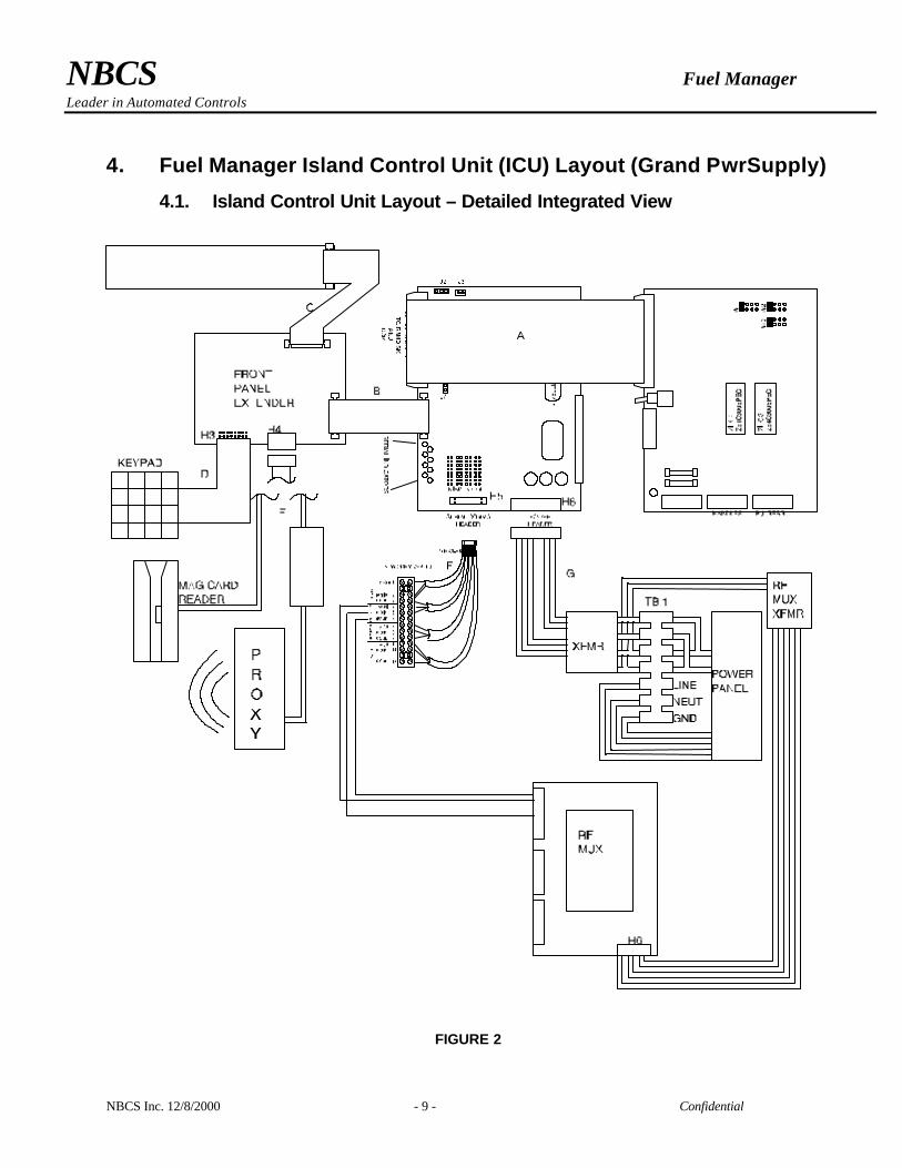
4. Fuel Manager Island Control Unit (ICU) Layout (Grand PwrSupply)
4.1. Island Control Unit Layout – Detailed Integrated View
FIGURE 2

NBCS Fuel Manager Leader in Automated Controls
NBCS Inc. 12/8/2000 - 10 - Confidential
4.2. Fuel Manager ICU Cable and Wiring Assemblies
Ribbon Cables
A. DCM Buss Cable, 50 pin: Connects MK2 Data bus lines to DCM.
B. Front Panel Extender Cable (FPE), 26 pin: Connects MK2 to FPE components
C. FPE - Display Cable, 26 pin: Connects the FPE to the Front Panel Display.
D. Keypad Cable, 10 pin, rainbow colored: Connects the FPE to Keypad
Wiring Cable Assemblies
E. DCM-Relay Board Cable Assembly:
F. RS-232 Communications Terminal Block #2 (TB2)
G. MK2 Power Cable Assembly
NBCS Fuel Manager Leader in Automated Controls
NBCS Inc. 12/8/2000 - 11 - Confidential
4.3. ICU’s MK2 Microprocessor Board
NBCS Fuel Manager Leader in Automated Controls
NBCS Inc. 12/8/2000 - 12 - Confidential
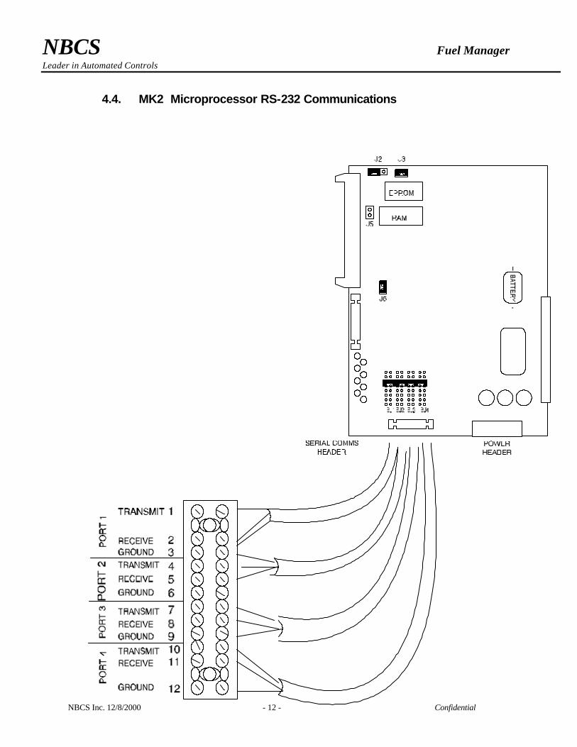
4.4. MK2 Microprocessor RS-232 Communications

NBCS Fuel Manager Leader in Automated Controls
NBCS Inc. 12/8/2000 - 13 - Confidential
4.5. Front Panel Extender Board (FPE)
NBCS Fuel Manager Leader in Automated Controls
NBCS Inc. 12/8/2000 - 14 - Confidential
4.6. Dispenser Control Module (DCM)
NBCS Fuel Manager Leader in Automated Controls
NBCS Inc. 12/8/2000 - 15 - Confidential
4.7. Solid State Relay Board ( 4 hose )
NBCS Fuel Manager Leader in Automated Controls
NBCS Inc. 12/8/2000 - 16 - Confidential
4.8. New Style ICU Power Supply Board

NBCS Fuel Manager Leader in Automated Controls
NBCS Inc. 12/8/2000 - 17 - Confidential
Fuel Manager ICU
Installation
Site Diagrams and Wiring Specifications
Section 5
ELECTRICAL NOTICE
1. Electrical equipment connected to associated apparatus should not use or
generate more than 250 volts r.m.s.
2. Installation shall be in accordance with the manufacturer’s instructions and the
National Electrical Code (ANSI/NFPS 70)
3. For guidance on installation see ANSI/ISA RF 12.6 “Installation of Intrinsically
Safe Instrument Systems in Class I Hazardous Locations.”
4. Tampering and replacement with non-factory components may adversely affect
the safe use of the system.
NBCS Fuel Manager Leader in Automated Controls
NBCS Inc. 12/8/2000 - 18 - Confidential
5. Fuel Manager Site Diagrams
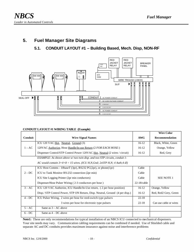
5.1. CONDUIT LAYOUT #1 – Building Based, Mech. Disp, NON-RF
CONDUIT LAYOUT #1 WIRING TABLE (Example)
Conduit
Wire Signal Names
AWG
Wire Color
Recommendation
ICU 120 VAC Hot, Neutral, Ground (3) 16-12 Black, White, Green
1 – AC 120VAC Authorize, Hose Handle/In-use Return (2 FOR EACH HOSE:) 16-12 Orange, Yellow
Dispenser Control/STP Control Power 120VAC Hot, Neutral (2 wires / circuit) 16-12 Red, Grey
EXAMPLE: As shown above w/ two twin disp. and two STP circuits, conduit 1-
AC would contain 3+4+8 = 15 wires. (ICU H,N,Gnd; 2xSTP H,N; 4 Auth;4 dl)
2 – DC
ICU Host Comms - 10baseT (3pr), RS232 PC(2pr), or phone(1pr)
ICU to Tank Monitor RS-232 connection (2pr min)
ICU Site Logging Printer (2pr min conductors)
Dispenser/Hose Pulser Wiring ( 2-3 conductors per hose )
Cable
Cable
Cable
22-18/cable
SEE NOTE 1
3 – AC ICU 120 VAC Authorize, ICU Handle/In-Use return, ( 2 per hose position)
Disp./ STP Control Power, STP ON Return, Disp. Neutral, Ground (4 per disp.)
16-12
16-12
Orange, Yellow
Red, Red2 Grey, Green
4 – DC ICU Pulser Wiring, 2 wires per hose for reed-switch type pulsers
3 wires per hose for electronic type pulsers
22-18
22-18
Can use cable or wires
5 – AC Same as 3 – AC above
6 – DC Same as 4 – DC above
Note1: These are only recommendations for typical installation of an NBCS ICU connected to mechanical dispensers. Your site needs may vary. Communication cabling requirements can be combined if needed. Use of Shielded cable and separate AC and DC conduits provides maximum insurance against noise and interference problems
1 2 3
Swipe Card>>
M A G N E T I C
S T R I PF A C I N GT H I S
S I D E
S W I P E
S M O O T H L Y
1 2 34 5 67 8 9
0* #
C L R
R E V
M E N U
E N T E R
F u e l M a n a g e r
REDJACKETRELAY
REDJACKETRELAY
BREAKERPANEL
4
AC POWER CONDUIT
DC (LOW VOLTAGE) CONDUIT
DC (LOW VOLTAGE) CONDUIT
DC (LOW VOLTAGE) CONDUIT
AC POWER CONDUIT
L O G G I N GPRINTER
WIRE TROUGH (J-BOX)
AC POWER CONDUITCONDUIT 123456
HOST PC OR MODEM
SEAL-OFF
SEAL-OFF
NBCS Fuel Manager Leader in Automated Controls
NBCS Inc. 12/8/2000 - 19 - Confidential
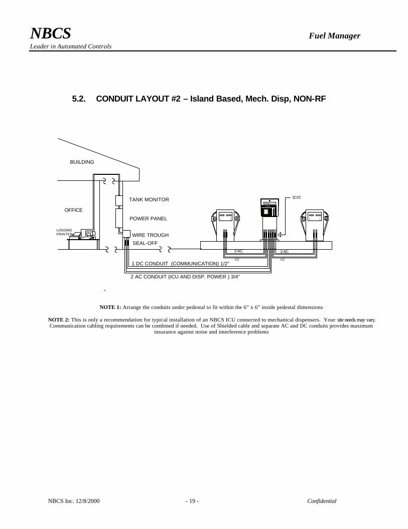
5.2. CONDUIT LAYOUT #2 – Island Based, Mech. Disp, NON-RF
NOTE 1: Arrange the conduits under pedestal to fit within the 6” x 6” inside pedestal dimensions
NOTE 2: This is only a recommendation for typical installation of an NBCS ICU connected to mechanical dispensers. Your site needs may vary. Communication cabling requirements can be combined if needed. Use of Shielded cable and separate AC and DC conduits provides maximum
insurance against noise and interference problems
1 2 3 4
Swipe Card>>
1 2 3
4 5 67 8 9
0* #
C L R
R E V
M E N U
E N T E R
Fuel Manager
M A G N E T I CS T R I P
F A C I N GT H I SS I D E
S W I P ES M O O T H L Y
BUILDING
OFFICE
PCLOGGINGPRINTER
TANK MONITOR
WIRE TROUGH
1 DC CONDUIT (COMMUNICATION) 1/2"
SEE NOTE
2 AC CONDUIT (ICU AND DISP. POWER ) 3/4"
SEAL-OFF3 AC
4 DC
3 AC
4 DC
POWER PANEL

NBCS Fuel Manager Leader in Automated Controls
NBCS Inc. 12/8/2000 - 20 - Confidential
5.3. CONDUIT LAYOUT #3 – Building Based, Mech. Disp, RF/AVID
NBCS Fuel Manager Leader in Automated Controls
NBCS Inc. 12/8/2000 - 21 - Confidential
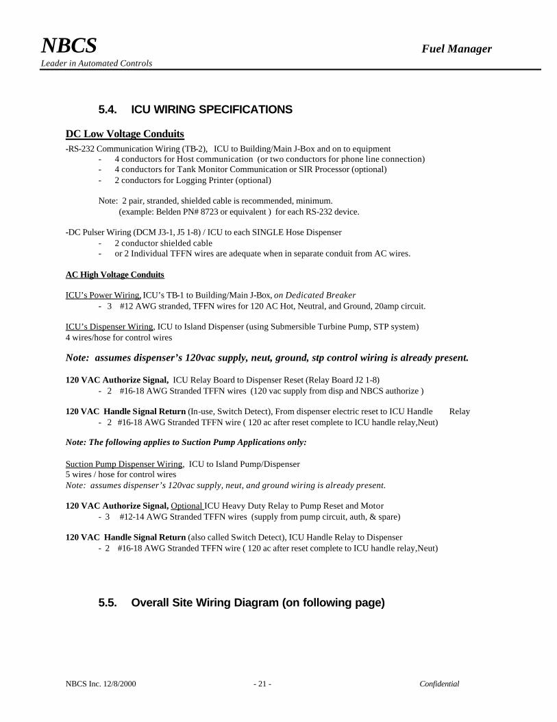
5.4. ICU WIRING SPECIFICATIONS
DC Low Voltage Conduits -RS-232 Communication Wiring (TB-2), ICU to Building/Main J-Box and on to equipment
- 4 conductors for Host communication (or two conductors for phone line connection) - 4 conductors for Tank Monitor Communication or SIR Processor (optional) - 2 conductors for Logging Printer (optional) Note: 2 pair, stranded, shielded cable is recommended, minimum. (example: Belden PN# 8723 or equivalent ) for each RS-232 device.
-DC Pulser Wiring (DCM J3-1, J5 1-8) / ICU to each SINGLE Hose Dispenser
- 2 conductor shielded cable - or 2 Individual TFFN wires are adequate when in separate conduit from AC wires.
AC High Voltage Conduits ICU’s Power Wiring, ICU’s TB-1 to Building/Main J-Box, on Dedicated Breaker - 3 #12 AWG stranded, TFFN wires for 120 AC Hot, Neutral, and Ground, 20amp circuit. ICU’s Dispenser Wiring, ICU to Island Dispenser (using Submersible Turbine Pump, STP system) 4 wires/hose for control wires Note: assumes dispenser’s 120vac supply, neut, ground, stp control wiring is already present. 120 VAC Authorize Signal, ICU Relay Board to Dispenser Reset (Relay Board J2 1-8) - 2 #16-18 AWG Stranded TFFN wires (120 vac supply from disp and NBCS authorize ) 120 VAC Handle Signal Return (In-use, Switch Detect), From dispenser electric reset to ICU Handle Relay - 2 #16-18 AWG Stranded TFFN wire ( 120 ac after reset complete to ICU handle relay,Neut) Note: The following applies to Suction Pump Applications only: Suction Pump Dispenser Wiring, ICU to Island Pump/Dispenser 5 wires / hose for control wires Note: assumes dispenser’s 120vac supply, neut, and ground wiring is already present. 120 VAC Authorize Signal, Optional ICU Heavy Duty Relay to Pump Reset and Motor - 3 #12-14 AWG Stranded TFFN wires (supply from pump circuit, auth, & spare) 120 VAC Handle Signal Return (also called Switch Detect), ICU Handle Relay to Dispenser - 2 #16-18 AWG Stranded TFFN wire ( 120 ac after reset complete to ICU handle relay,Neut)
5.5. Overall Site Wiring Diagram (on following page)

NBCS Fuel Manager Leader in Automated Controls
NBCS Inc. 12/8/2000 - 22 - Confidential

NBCS Fuel Manager Leader in Automated Controls
NBCS Inc. 12/8/2000 - 23 - Confidential
5.6. Dispenser Activation Process Description

NBCS Fuel Manager Leader in Automated Controls
NBCS Inc. 12/8/2000 - 24 - Confidential
Fuel Manager ICU
Trouble Shooting
Section 6
NBCS Fuel Manager Leader in Automated Controls
NBCS Inc. 12/8/2000 - 25 - Confidential
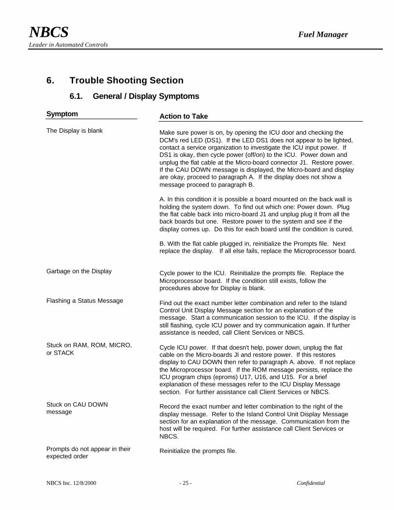
6. Trouble Shooting Section
6.1. General / Display Symptoms Symptom The Display is blank Garbage on the Display Flashing a Status Message Stuck on RAM, ROM, MICRO, or STACK Stuck on CAU DOWN message Prompts do not appear in their expected order
Action to Take Make sure power is on, by opening the ICU door and checking the DCM's red LED (DS1). If the LED DS1 does not appear to be lighted, contact a service organization to investigate the ICU input power. If DS1 is okay, then cycle power (off/on) to the ICU. Power down and unplug the flat cable at the Micro-board connector J1. Restore power. If the CAU DOWN message is displayed, the Micro-board and display are okay, proceed to paragraph A. If the display does not show a message proceed to paragraph B. A. In this condition it is possible a board mounted on the back wall is holding the system down. To find out which one: Power down. Plug the flat cable back into micro-board J1 and unplug plug it from all the back boards but one. Restore power to the system and see if the display comes up. Do this for each board until the condition is cured. B. With the flat cable plugged in, reinitialize the Prompts file. Next replace the display. If all else fails, replace the Microprocessor board. Cycle power to the ICU. Reinitialize the prompts file. Replace the Microprocessor board. If the condition still exists, follow the procedures above for Display is blank. Find out the exact number letter combination and refer to the Island Control Unit Display Message section for an explanation of the message. Start a communication session to the ICU. If the display is still flashing, cycle ICU power and try communication again. If further assistance is needed, call Client Services or NBCS. Cycle ICU power. If that doesn't help, power down, unplug the flat cable on the Micro-boards JI and restore power. If this restores display to CAU DOWN then refer to paragraph A. above. If not replace the Microprocessor board. If the ROM message persists, replace the ICU program chips (eproms) U17, U16, and U15. For a brief explanation of these messages refer to the ICU Display Message section. For further assistance call Client Services or NBCS. Record the exact number and letter combination to the right of the display message. Refer to the Island Control Unit Display Message section for an explanation of the message. Communication from the host will be required. For further assistance call Client Services or NBCS. Reinitialize the prompts file.
NBCS Fuel Manager Leader in Automated Controls
NBCS Inc. 12/8/2000 - 26 - Confidential
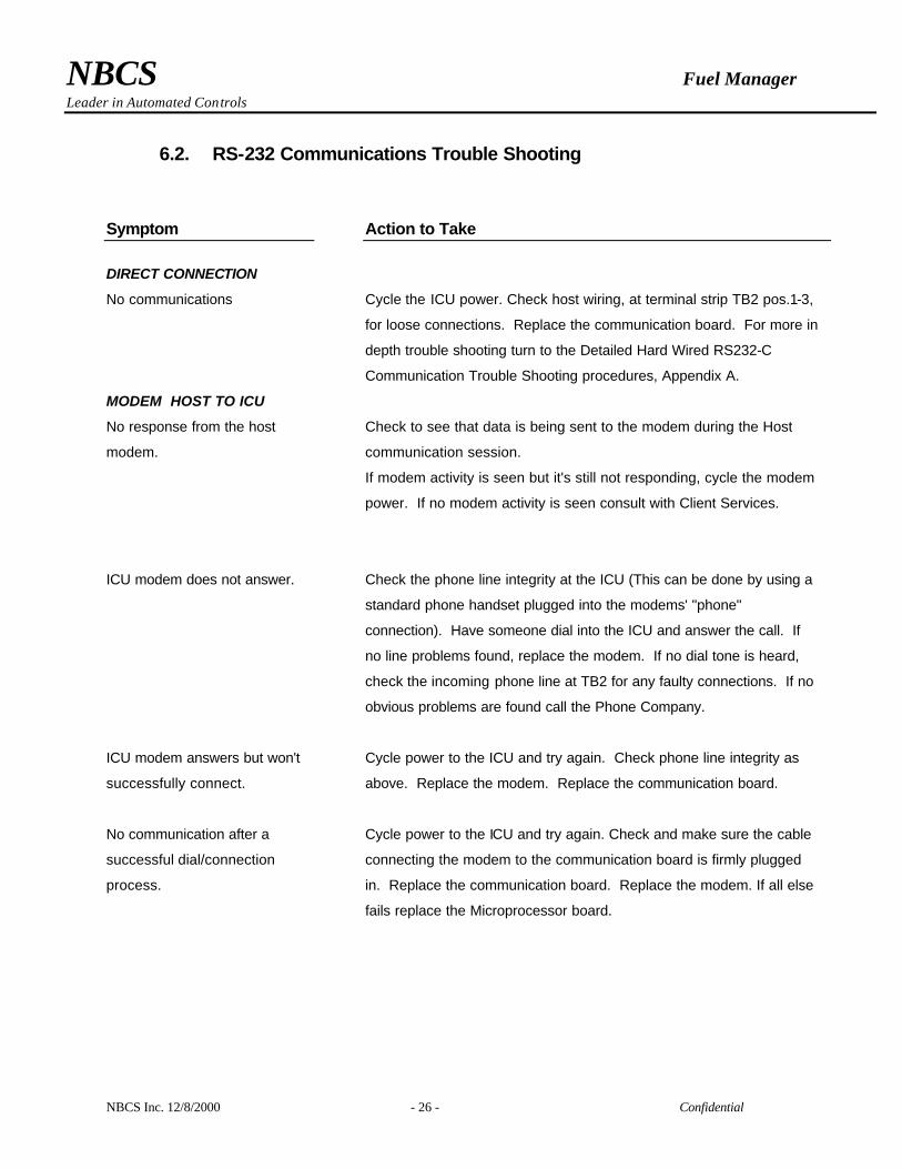
6.2. RS-232 Communications Trouble Shooting Symptom
DIRECT CONNECTION
No communications
MODEM HOST TO ICU
No response from the host
modem.
ICU modem does not answer.
ICU modem answers but won't
successfully connect.
No communication after a
successful dial/connection
process.
Action to Take
Cycle the ICU power. Check host wiring, at terminal strip TB2 pos.1-3,
for loose connections. Replace the communication board. For more in
depth trouble shooting turn to the Detailed Hard Wired RS232-C
Communication Trouble Shooting procedures, Appendix A.
Check to see that data is being sent to the modem during the Host
communication session.
If modem activity is seen but it's still not responding, cycle the modem
power. If no modem activity is seen consult with Client Services.
Check the phone line integrity at the ICU (This can be done by using a
standard phone handset plugged into the modems' "phone"
connection). Have someone dial into the ICU and answer the call. If
no line problems found, replace the modem. If no dial tone is heard,
check the incoming phone line at TB2 for any faulty connections. If no
obvious problems are found call the Phone Company.
Cycle power to the ICU and try again. Check phone line integrity as
above. Replace the modem. Replace the communication board.
Cycle power to the ICU and try again. Check and make sure the cable
connecting the modem to the communication board is firmly plugged
in. Replace the communication board. Replace the modem. If all else
fails replace the Microprocessor board.
NBCS Fuel Manager Leader in Automated Controls
NBCS Inc. 12/8/2000 - 27 - Confidential
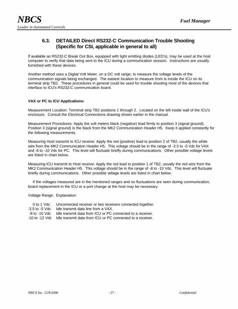
6.3. DETAILED Direct RS232-C Communication Trouble Shooting (Specific for CSI, applicable in general to all)
If available an RS232-C Break Out Box, equipped with light emitting diodes (LED's), may be used at the host computer to verify that data being sent to the ICU during a communication session. Instructions are usually furnished with these devices. Another method uses a Digital Volt Meter, on a DC volt range, to measure the voltage levels of the communication signals being exchanged. The easiest location to measure from is inside the ICU on its terminal strip TB2. These procedures in general could be used for trouble shooting most of the devices that interface to ICU's RS232-C communication board. VAX or PC to ICU Applications: Measurement Location: Terminal strip TB2 positions 1 through 2. Located on the left inside wall of the ICU's enclosure. Consult the Electrical Connections drawing shown earlier in the manual. Measurement Procedures: Apply the volt meters black (negative) lead firmly to position 3 (signal ground). Position 3 (signal ground) is the black from the MK2 Communication Header H5. Keep it applied constantly for the following measurements. Measuring Host transmit to ICU receive: Apply the red (positive) lead to position 2 of TB2, usually the white wire from the MK2 Communication Header H5. This voltage should be in the range of -3.5 to -5 Vdc for VAX and -8 to -10 Vdc for PC. This level will fluctuate briefly during communications. Other possible voltage levels are listed in chart below. Measuring ICU transmit to Host receive: Apply the red lead to position 1 of TB2, usually the red wire from the MK2 Communication Header H5. This voltage should be in the range of -8 to -10 Vdc. This level will fluctuate briefly during communications. Other possible voltage levels are listed in chart below. If the voltages measured are in the mentioned ranges and no fluctuations are seen during communication, board replacement in the ICU or a port change at the host may be necessary. Voltage Range: Explanation: 0 to 1 Vdc Unconnected receiver or two receivers connected together. -3.5 to -5 Vdc Idle transmit data line from a VAX. -8 to -10 Vdc Idle transmit data from ICU or PC connected to a receiver. -10 to -12 Vdc Idle transmit data from ICU or PC connected to a receiver.
NBCS Fuel Manager Leader in Automated Controls
NBCS Inc. 12/8/2000 - 28 - Confidential
6.4. Dispenser / Pump Activation Trouble Shooting Symptom Does not turn on Early shut off with non-zero transaction quantity Early shut off with zero quantity transaction Zero quantities on transaction Pulser vs. Pump quantity error
Action to Take Turn the Dispenser Control Module (DCM) Boards' AUTO/MANUAL switch to the manual position. If the device is still not working, replace the Relay board. If the device does work in manual mode, replace the DCM. Inspect the wiring between the DCM and the Relay board for loose connections. If these procedures do not remedy the problem proceed to the Detailed Pump Interface Trouble Shooting section. With this symptom it's possible the Handle (Busy) signal is not being sensed at the DCM boards' Handle input J4. As a result the ICU will stop the transaction after its specific timeout. Check the handle wiring, at the DCM's J4, for any loose or faulty connections. If the wiring appears to be okay replace the DCM. If board replacement does not help, proceed to the Detailed Pump Interface Trouble Shooting section. This section will also provide general information on applications that use an optional relay to convert certain dispensers high voltage handle signal to the ICU's 12 VDC. Usually this symptom occurs when no pulses are being received at the DCM pulser input J5. See the section handling pulser or quantity problems. The action for an Early Shut Off with Non-Zero Quantities could also apply. Check the pulser input wiring, at the DCM's corresponding position on J5. If no problems found, replace the DCM Board. If this does not remedy the problem proceed to the Detailed Pump Interface Trouble Shooting pulser section or call a qualified pump service company for assistance. Check the pulse per unit setting in the ICU's pump configuration file. If it's okay try reinitializing the ICU's pump file. If the problem still exists have the pulser in the dispenser replaced. If all else fails replace the Dispenser Control Module board.
6.5. Card Reader and Keypad Problems Cards do not read Cards read erratically Keypad does not work Keypad bounce (duplicate characters)
Clean the card reader. Check for loose connections. Replace the card reader. Reinitialize the prompts file. If all else fails, replace the Microprocessor board. Clean the card reader with the ICU card reader cleaning kit. If this kit is not available, a clean soft cloth and isopropyl alcohol may be used. If cleaning failed to remedy the problem, replace the card reader. Inspect the keypad and keypad cable for damage. Replace the keypad and/or cable. Reinitialize the ICU's prompts file. If all else fails, replace the Microprocessor board. Rapid characters output after a single touch indicates keypad wear. Replace the keypad

NBCS Fuel Manager Leader in Automated Controls
NBCS Inc. 12/8/2000 - 29 - Confidential
Recommended


![ATA Specification 103 · 2017-12-11 · 2-2. Jet Fuel Specification & Purity Standards 1. Specification Requirements Jet fuel shall conform to [ASTM D1655], Latest Revision, "Standard](https://img.dokumen.tips/doc/110x75/5e6b1a58508d730b5f3c397f/ata-specification-103-2017-12-11-2-2-jet-fuel-specification-purity-standards.jpg)