Frimeda LiFTiNG aNCHOr SYSTem TPA 11-EE
CONCRETE

Head im BalkenFRIMEDA offers with its lifting anchor system a proven, safe, robust and eco-nomical system for the transport and installation of prefabricated concrete components. The system is easy to use, and its functional capability is easy to check by visual inspection. Thanks to the large range of special transport anchors available and a comprehensive range of accessories, the FRIMEDA lifting anchor system can be adapted to almost all transport and installation applications.
As for all lifting anchor systems, the safe use of our system requires a basic knowledge of the selection and use of the individual system components. This brochure is intended to serve as a dimensioning aid and installation instructions. Please read these instruc-tions carefully, and ensure that they are kept available at the point of use. The conscientious use of our system will ensure at all times the safe and reliable transport of your prefabricated concrete components.
Software support
To ease anchor selection and the dimensioning of the required an-chors, we will be happy to provide you with our free dimensioning programme TPA-WIN. After entering the required anchor type, the com-ponent dimensions and the transport conditions (traverse, inclination etc.), this program calculates the matching anchor and the additional reinforce-ment required. Scale drawings and parts lists can also be printed out.
Technical consultation
The staff of our Technical Office and our special sales consultants will advise and assist you in the solution of any special questions in connection with the FRIMEDA lifting anchor system. The relevant addresses can be found on the rear cover of the brochure.
Some of the advantages of the FRIMEDA lifting anchor system
• Wide range of anchor types• Manual ring couplings and ring
couplings with manual or pneumatic remote release
• Easy, safe and quick connection and disconnection of the ring clutches
• No confusing of load groups pos-sible
• No preferential direction, ring clut-ches remain mobile all round under load
• System proven over many years• Positive engagement of locking bolt
into the anchor.• CE-Marking• Hot-dip galvanised version available
FRIMEDA LIFTINg ANCHOR SySTEM
Product In format ion
The Quality Management System of Halfen GmbH is certified for the locations in Germany, Austria, Poland, Switzerland and the Czech Republic according to DIN EN ISO 9001:2008, Certificate No. QS-281 HH.

CONTENTS
System overview 4
The range 8
FRIMEDA lifting anchor system 11
System description 11Dimensioning 13Multiple suspension 15Dimensioning examples 17Calculation of load group tables 18
FRIMEDA lifting anchors 19
Spread anchors TPA-FS 19Two-hole anchors TPA-FZ 24Erection anchor TPA-FA / Unilateral erection anchor TPA-FE 27Plate anchor TPA-FP 30Flat foot anchor TPA-FF 31Garage anchor TPA-FG 33Double ended column anchor TPA-FD 34Sandwich panel anchor TPA-FX 36Universal anchor TPA-FU 1.25-12 37
FRIMEDA recess formers, holding plates and holding bolts 38
Recess former 39Holding plates and holding bolts 40Accessories 41
FRIMEDA ring clutches 42
Ring clutch TPA-R1 with clasp for manual release 42Ring clutch with cable loop TPA-R2 42Ring clutch with cable loop TPA-R3 42Checking connection/lifting equipment 43Ring clutch TPA-F1 with pneumatic release 44Ring clutch TPA-F2 with manual remote release by bowden cable 46
Anchor installation 48
Notes and examples 48Floating installation 48Attachment to side formwork (wood) 48Attachment to side formwork (wood/steel) 48Attachment to side formwork (steel) 48
FRIMEDA lifting anchor system 49
Application and incorrect use 50Contact 51

SySTEM OvERvIEw
FRIMEDA TPA-Anchor
Spread anchor TPA-FS
Main applications:
Columns, beams, trusses, wall units,
π-slabs
Parameters:
Component thickness, concrete
grade, reinforcement
see page 19
Double ended column anchor TPA-FD
Main applications:
Columns
Parameters:
Component thickness, concrete
grade, reinforcement
see page 34
Flat foot anchor TPA-FF
Main applications:
Ceiling slabs with surface-
embedded
anchors, tubes
Parameters:
Component thickness, con-
crete grade, reinforcement
see page 31
Two hole anchor TPA-FZ
Main applications:
Prestressed concrete trusses,
thinwalled elements, low strength
concrete (e.g. lightweight concrete)
Parameters:
Component thickness, concrete
grade, reinforcement
see page 24
Sandwich panel anchor TPA-FX
Main applications:
Sandwich panels
Parameters:
Component thickness, concrete
grade, reinforcement
see page 36
garage anchor TPA-Fg
Main applications:
Precast concrete garages,
embedding in floor or
ceiling slab
Parameters:
Component thickness,
concrete grade
see page 33
Erection anchor TPA-FA
Main applications:
Thin-walled concrete elements,
being lifted from a horizontal to a
perpendicular position.
Parameters:
Component thickness, concrete
grade, reinforcement
see page 27
Universal anchor TPA-FU
Main applications:
see TPA-FS, TPA-FZ and TPA-FA
Parameters:
Component thickness, concrete
grade, reinforcement
see page 37
Plate anchor TPA-FP
Main applications:
Very thin ceiling slabs with
surface-embedded anchors
Parameters:
Component thickness, con-
crete grade, reinforcement
see page 30
Unilateral erection anchor TPA-FE
Main applications:
Thin-walled concrete elements,
being lifted from a horizontal to a
perpendicular position.
Parameters:
Component thickness, concrete
grade, reinforcement
see page 27
4

SySTEM OvERvIEw
Ring clutch TPA-R1
with shackle for manual releaseLoad group 2,5 - 26,0
see page 42
Ring clutch TPA-R2
with wire cables for manual releaseLoad group 1,25 - 10,0
see page 42
Ring clutch TPA-R3
with wire cables for manual releaseLoad group 26,0
see page 42
Ring clutch TPA-F1
with pneumatic remote-control releaseLoad group 2,5 - 26,0
see page 44
Ring clutch TPA-F2
with manual remote control by bow-den cableLoad group 2,5 - 26,0
see page 46
FRIMEDA at tachment l inks
5

TPA-A1Material: PlasticApplication: For all anchors except TPA-FU and TPA-FGInstallation: Holding plates H1, H2, H4,
HM; holding bolts S1 or S2Special features: High durability and good resi-
stance to formwork treatment agents.
TPA-A2Material: RubberApplication: For anchors TPA-FS, TPA-FZ,
TPA-FD, TPA-FP and TPA-FFInstallation: Holding plate H3; holding
bolt S1 in combination with holding plate H3
Special features: High durability and good resi-stance to formwork treatment agents.
TPA-A3Material: RubberApplication: For anchor TPA-FGInstallation: By locking bracketSpecial features: High durability and good resi-
stance to formwork treatment agents.
TPA-A4Material: Plastic (hard)Application: For all anchors except TPA-FU and TPA-FGInstallation: Holding bolts S1Special features: High durability and good resi-
stance to formwork treatment agents.
TPA-A5Material: SteelApplication: For all anchors except TPA-FU and TPA-FGInstallation: Holding bolts S1Special features: High durability and good resi-
stance to formwork treatment agents.
TPA-A7Material: PlasticApplication: For Universal anchor TPA-FUInstallation: Holding plate H1 and holding bolt S1Special features: Only for load group 1,25 ! Specially small recess High durability and good resi-
stance to formwork treatment agents.
TPA-A8Material: PlasticApplication: For anchors of load group 2,5Installation: Consists of two parts, which
are pressed together above the anchor head. Attachment to the formwork with a wedge, which is pressed between the two attachment tabs
Special features: For one-time use only!
TPA-A9Material: PlasticApplication: Specially suitable for TPA-FS,
TPA-FZ, TPA- FF und TPA-FD,not suitable for TPA-FA, TPAFE, TPA-FU, TPA-FG and TPA-FXInstallation: Holding plates H1, H2, HM;
Holding bolts S1 or S2Special features: As for TPA-A1, but for recesses
without protruding concrete tongues.
SySTEM OvERvIEw
FRIMEDA recess former ( see page 38/39 )
TPA-AMMaterial: PlasticApplication: For all anchors except TPA-FU and TPA-FGInstallation: MagneticSpecial features: High durability and good resi-
stance to formwork treatment agents.
66

SySTEM OvERvIEw
FRIMEDA hold ing p lates and hold ing bol ts ( see page 38/40 )
TPA-H1Application: For recess formers TPA-A1,
TPA-A7 and TPA-A9
load groupe 1,25 for TPA-A7
Installation: Fixing to the form work
TPA-H2Application: For recess former TPA-A1 and
TPA-A9
Installation: For floating installation
TPA-H3Application: For recess former TPA-A2
Installation: For attachment to the formwork
with retaining bolt S1 or by
nailing
TPA-HMApplication: For recess formers TPA-A1,
TPA-A9 to load group 10t
Installation: Fixing to the steel form work
Note: Magnetic.
TPA-S1Application: For recess formers TPA-A1, TPA-
A7, TPA-A4, TPA-A5, TPA-A9,
TPA-A2 only in combination
with holding plate TPA-H3
TPA-S2Application: For recess formers TPA-A1 and
TPA-A9
Load group 1,25
TPA-v1Material: PolystyreneApplication: Recess filler to keep the recess
clean during stargeInstallation: TPA-A1, TPA-A2, TPA-A3,
TPA-A4, TPA-A5, TPA-A9 and TPA-AM
7

Spread anchor TPA-FS
Load group
[t]
DesignationOrder No.0070.010-
DesignationOrder No.0070.110-
2,5
mill
fin
ish
TPA-FS 0,7-11 00001
hot-d
ip g
alva
nise
d
TPA-FS 0,7-11 FV 00032
TPA-FS 1,4-11 00002 TPA-FS 1,4-11 FV 00033
TPA-FS 1,4-16 00003 TPA-FS 1,4-16 FV 00034
TPA-FS 2,0-13 00004 TPA-FS 2,0-13 FV 00035
TPA-FS 2,0-16 00005 TPA-FS 2,0-16 FV 00036
TPA-FS 2,0-21 00006 TPA-FS 2,0-21 FV 00037
TPA-FS 2,5-15 00007 TPA-FS 2,5-15 FV 00038
TPA-FS 2,5-20 00008 TPA-FS 2,5-20 FV 00039
TPA-FS 2,5-25 00009 TPA-FS 2,5-25 FV 00040
5
TPA-FS 3,0-16 00010 TPA-FS 3,0-16 FV 00041
TPA-FS 3,0-20 00011 TPA-FS 3,0-20 FV 00042
TPA-FS 3,0-28 00012 TPA-FS 3,0-28 FV 00043
TPA-FS 4,0-18 00013 TPA-FS 4,0-18 FV 00044
TPA-FS 4,0-24 00014 TPA-FS 4,0-24 FV 00045
TPA-FS 4,0-32 00015 TPA-FS 4,0-32 FV 00046
TPA-FS 5,0-18 00016 TPA-FS 5,0-18 FV 00047
TPA-FS 5,0-24 00017 TPA-FS 5,0-24 FV 00048
TPA-FS 5,0-40 00018 TPA-FS 5,0-40 FV 00049
10
TPA-FS 7,5-26 00022 TPA-FS 7,5-26 FV 00053
TPA-FS 7,5-30 00023 TPA-FS 7,5-30 FV 00054
TPA-FS 7,5-42 00024 TPA-FS 7,5-42 FV 00055
TPA-FS 10,0-30 00025 TPA-FS 10,0-30 FV 00056
TPA-FS 10,0-37 00026 TPA-FS 10,0-37 FV 00057
TPA-FS 10,0-52 00027 TPA-FS 10,0-52 FV 00058
26
TPA-FS 14,0-37 00028 TPA-FS 14,0-37 FV 00059
TPA-FS 14,0-46 00029 TPA-FS 14,0-46 FV 00060
TPA-FS 22,0-50 00030 TPA-FS 22,0-50 FV 00061
TPA-FS 22,0-62 00031 TPA-FS 22,0-62 FV 00062
Two hole anchor TPA-FZ
Load group
[t]Designation
Order No.0070.020-
DesignationOrder No.0070.110-
2,5
mill
fin
ish
TPA-FZ 1,4- 9 00002
hot-d
ip g
alva
nise
d
TPA-FZ 1,4- 9 FV 00064
TPA-FZ 2,0- 9 00003 TPA-FZ 2,0- 9 FV 00065
TPA-FZ 2,5- 9 00004 TPA-FZ 2,5- 9 FV 00066
5
TPA-FZ 3,0-12 00005 TPA-FZ 3,0-12 FV 00067
TPA-FZ 4,0-12 00006 TPA-FZ 4,0-12 FV 00068
TPA-FZ 5,0-12 00007 TPA-FZ 5,0-12 FV 00069
10TPA-FZ 7,5-16 00009 TPA-FZ 7,5-16 FV 00071
TPA-FZ 10,0-17 00010 TPA-FZ 10,0-17 FV 00072
26
TPA-FZ 14,0-24 00011 TPA-FZ 14,0-24 FV 00073
TPA-FZ 22,0-30 00013 TPA-FZ 22,0-30 FV 00075
TPA-FZ 26,0-30 00012 TPA-FZ 26,0-30 FV 00074
Erection anchor TPA-FA
Load group
[t]
DesignationOrder No.0070.030-
DesignationOrder No.0070.110-
2,5
mill
fin
ish
TPA-FA 1,4-20 00001
hot-d
ip g
alva
nise
d
TPA-FA 1,4-20 FV 00001
TPA-FA 2,5-23 00002 TPA-FA 2,5-23 FV 00002
5TPA-FA 4,0-27 00003 TPA-FA 4,0-27 FV 00003
TPA-FA 5,0-29 00004 TPA-FA 5,0-29 FV 00004
10TPA-FA 7,5-32 00005 TPA-FA 7,5-32 FV 00005
TPA-FA 10,0-39 00006 TPA-FA 10,0-39 FV 00006
26
TPA-FA 12,5-50 00007 TPA-FA 12,5-50 FV 00007
TPA-FA 17,0-50 00008 TPA-FA 17,0-50 FV 00008
TPA-FA 22,0-50 00009 TPA-FA 22,0-50 FV 00009
Unilateral erection anchor TPA-FE
Load group
[t]
DesignationOrder No.0070.040-
DesignationOrder No.0070.110-
2,5
mill
fin
ish
TPA-FE 1,4-20 00001
hot-d
ip g
alva
nise
d
TPA-FE 1,4-20 FV 00010
TPA-FE 2,5-23 00002 TPA-FE 2,5-23 FV 00011
5TPA-FE 4,0-27 00003 TPA-FE 4,0-27 FV 00012
TPA-FE 5,0-29 00004 TPA-FE 5,0-29 FV 00013
10TPA-FE 7,5-32 00005 TPA-FE 7,5-32 FV 00014
TPA-FE 10,0-39 00006 TPA-FE 10,0-39 FV 00015
26
TPA-FE 12,5-50 00007 TPA-FE 12,5-50 FV 00016
TPA-FE 17,0-50 00008 TPA-FE 17,0-50 FV 00017
TPA-FE 22,0-50 00009 TPA-FE 22,0-50 FV 00018
Flat Foot anchor TPA-FF
Load group
[t]
DesignationOrder No.0070.070-
DesignationOrder No.0070.110-
2,5
mill
fin
ish
TPA-FF 0,7- 6 00001
hot-d
ip g
alva
nise
d
TPA-FF 0,7- 6 FV 00019
TPA-FF 1,4- 6 00002 TPA-FF 1,4- 6 FV 00020
TPA-FF 2,0- 7 00003 TPA-FF 2,0- 7 FV 00021
TPA-FF 2,5- 7 00004 TPA-FF 2,5- 7 FV 00022
5
TPA-FF 3,0- 9 00005 TPA-FF 3,0- 9 FV 00023
TPA-FF 4,0-11 00006 TPA-FF 4,0-11 FV 00024
TPA-FF 5,0-12 00007 TPA-FF 5,0-12 FV 00025
10TPA-FF 7,5-17 00009 TPA-FF 7,5-17 FV 00027
TPA-FF 10,0-20 00010 TPA-FF 10,0-20 FV 00028
26
TPA-FF 12,5-22 00011 TPA-FF 12,5-22 FV 00029
TPA-FF 17,0-27 00012 TPA-FF 17,0-27 FV 00030
TPA-FF 22,0-31 00013 TPA-FF 22,0-31 FV 00031
Load range 1,4t-17,0t
Load range 22,0t
Load range 1,4t-17,0t
Load range 22,0t
Load range2,5t-5,0t
Load range10,0t-26,0t
THE RANgE
TPA-Anchor
8

Double ended column anchor TPA-FD
Load group
DesignationOrder No.0080.010-
DesignationOrder No.0070.110-
2,5
mill
fin
ish
TPA-FD 2,5-23 00001
hot-d
ip g
alva
nise
d
TPA-FD 2,5-23 00080
TPA-FD 2,5-28 00002 TPA-FD 2,5-28 00081
TPA-FD 2,5-33 00003 TPA-FD 2,5-33 00082
5
TPA-FD 5,0-23 00004 TPA-FD 5,0-23 00083
TPA-FD 5,0-28 00005 TPA-FD 5,0-28 00084
TPA-FD 5,0-33 00006 TPA-FD 5,0-33 00085
TPA-FD 5,0-38 00007 TPA-FD 5,0-38 00086
TPA-FD 5,0-43 00008 TPA-FD 5,0-43 00087
TPA-FD 5,0-48 00009 TPA-FD 5,0-48 00088
10
TPA-FD 7,5-26 00010 TPA-FD 7,5-26 00089
TPA-FD 7,5-31 00011 TPA-FD 7,5-31 00090
TPA-FD 7,5-36 00012 TPA-FD 7,5-36 00091
TPA-FD 7,5-41 00013 TPA-FD 7,5-41 00092
TPA-FD 7,5-46 00014 TPA-FD 7,5-46 00093
TPA-FD 10,0-26 00015 TPA-FD 10,0-26 00094
TPA-FD 10,0-31 00016 TPA-FD 10,0-31 00095
TPA-FD 10,0-36 00017 TPA-FD 10,0-36 00096
TPA-FD 10,0-41 00018 TPA-FD 10,0-41 00097
TPA-FD 10,0-46 00019 TPA-FD 10,0-46 00098
26
TPA-FD 12,5-36 00020 TPA-FD 12,5-36 00099
TPA-FD 12,5-41 00021 TPA-FD 12,5-41 00100
TPA-FD 12,5-46 00022 TPA-FD 12,5-46 00101
TPA-FD 17,5-36 00023 TPA-FD 17,5-36 00102
TPA-FD 17,0-41 00024 TPA-FD 17,0-41 00103
TPA-FD 17,0-46 00025 TPA-FD 17,0-46 00104
TPA-FD 22,0-41 00026 TPA-FD 22,0-41 00105
TPA-FD 22,0-46 00027 TPA-FD 22,0-46 00106
TPA-FD 22,0-56 00028 TPA-FD 22,0-56 00107
Plate anchor TPA-FP
Load group
DesignationOrder No.0070.050-
hot-d
ip g
alva
nise
d DesignationOrder No.0070.110-
2,5
mill
fin
ish
TPA-FP 1,4- 5 00001 TPA-FP 1,4- 5 FV 00076
TPA-FP 2,5- 8 00002 TPA-FP 2,5- 8 FV 00077
5 TPA-FP 5,0-12 00003 TPA-FP 5,0-12 FV 00078
10 TPA-FP 10,0-16 00004 TPA-FP 10,0-16 FV 00079
Sandwich panel anchor TPA-FX
Load group
DesignationOrder No.0070.090-
hot-d
ip g
alva
nise
d
DesignationOrder No.0070.090-
2,5
mill
fin
ish
TPA-FX 2,5-25 00001 TPA-FX 2,5-25 FV 00006
5 TPA-FX 5,0-30 00002 TPA-FX 5,0-30 FV 00007
10TPA-FX 7,5-35 00003 TPA-FX 7,5-35 FV 00008
TPA-FX 10,0-35 00004 TPA-FX 10,0-35 FV 00009
26 TPA-FX 17,0-40 00005 TPA-FX 17,0-40 FV 00010
Universal anchor TPA-FU
Load group
Designationmill finish
Order No.0070.100-
Material
1,25 TPA-FU 1,25-12 00001 mill finish
1,25 TPA-FU 1,25-12 FV 00003 hot-dip galvanised
1,25 TPA-FU 1,25-12 A2 00002 stainless steel A2 (W 1.4301)
garage anchor TPA-FP
Load group
Designationmill finish
Order No.0070.060-
Designationhot-dip galvanised
Order No.0070.110-
5,0 TPA-FG 4,0 - 7 00001 TPA-FG 4,0 - 7 FV 00076
THE RANgE
TPA-Anchor / TPA-Attachment l inks
9

Holding plates Holding bolts
Load group
[t]
TPA-H1 TPA-H2 TPA-H3 TPA-HM TPA-S1 TPA-S2
DesignationOrder No.0073.010-
DesignationOrder No.0073.020-
DesignationOrder No.0073.030-
DesignationOrder No.0073.050-
DesignationOrder No.0073.060-
DesignationOrder No.0073.070-
1,25 TPA-H1 1,25 00001 - - - - - -TPA-S1-M 8 00001
- -2,5 TPA-H1 2,5 00002 TPA-H2 2,5 00001 TPA-H3 2,5 00001 TPA-HM 2,5 00001
TPA-S2-M 8 000015 TPA-H1 5,0 00003 TPA-H2 5,0 00002 TPA-H3 5,0 00002 TPA-HM 5,0 0000210 TPA-H1 10,0 00004 TPA-H2 10,0 00003 TPA-H3 10,0 00003 TPA-HM 10,0 00003 TPA-S1-M12 00002
TPA-S2-M12 0000226 TPA-H1 26,0 00005 TPA-H2 26,0 00004 - - - - TPA-S1-M16 00003
Ring clutches Ring clutches with remote control release Spares
Load group
[t]
TPA-R1 TPA-R2 TPA-R3 TPA-F1 TPA-F2 TPA-R-E1
Spare locking bolt
zi = galvanised version
DesignationOrder No.0071.010-
DesignationOrder No.0071.020-
DesignationOrder No.0071.020-
DesignationOrder No.0071.030-
DesignationOrder No.0071.040-
DesignationOrder No.0071.060-
1,25 - - TPA-R2 1,25 00001 - - -
page 44
-
page 46
TPA-R-E1 1,25-Zi 000012,5 TPA-R1 2,5 00001 TPA-R2 2,5 00002 - - TPA-F1 2,5 TPA-F2 2,5 TPA-R-E1 2,5-Zi 000025 TPA-R1 5,0 00002 TPA-R2 5,0 00003 - - TPA-F1 5,0 TPA-F2 5,0 TPA-R-E1 5,0-Zi 0000310 TPA-R1 10,0 00003 TPA-R2 10,0 00004 - - TPA-F1 10,0 TPA-F2 10,0 TPA-R-E1 10,0 00004
22/26 TPA-R1 26,0 00004 - - TPA-R3 26,0 00005 TPA-F1 22,0 TPA-F2 22,0 TPA-R-E1 26,0 00005
Recess former Recess filler Asseccories
Load group
[t]
TPA-A8 TPA-A9 TPA-AM TPA-v1 TPA-A-Z1 TPA-A-E1
DesignationOrder No.0072.080-
DesignationOrder No.0072.090-
DesignationOrder No.0072.100-
DesignationOrder No.0073.080-
DesignationOrder No.0072.120-
DesignationOrder No.0072.120-
1,25 - - - - - - - - - - - -2,5 TPA-A8 2,5 00001 TPA-A9 2,5 00001 TPA-AM 2,5 00001 TPA-V1 2,5 00001 TPA-A-Z1 2,5 00006 TPA-A-E1 2,5 000025 - - TPA-A9 5,0 00002 TPA-AM 5,0 00002 TPA-V1 5,0 00002 TPA-A-Z1 5,0 00007 TPA-A-E1 5,0 0000310 - - TPA-A9 10,0 00003 - - TPA-V1 10,0 00003 TPA-A-Z1 10,0 00008 TPA-A-E1 10,0 0000426 - - TPA-A9 26,0 00004 - - TPA-V1 26,0 00004 TPA-A-Z1 26,0 00009 TPA-A-E1 26,0 00005
Recess former
Load group
[t]
TPA-A1 TPA-A2 TPA-A3 TPA-A4 TPA-A5 TPA-A7
incl. TPA-A-E1 incl. TPA-A-E1
DesignationOrder No.0072.010-
DesignationOrder No.0072.020-
DesignationOrder No.0072.030-
DesignationOrder No.0072.040-
DesignationOrder No.0072.050-
DesignationOrder No.0072.070-
1,25 - - - - - - - - - - TPA-A7 1,25 000012,5 TPA-A1 2,5 00001 TPA-A2 2,5 00001 - - TPA-A4 2,5 00001 TPA-A5 2,5 00001 - -5 TPA-A1 5,0 00002 TPA-A2 5,0 00002 TPA-A3 5,0 00001 TPA-A4 5,0 00002 TPA-A5 5,0 00002 - -10 TPA-A1 10,0 00003 TPA-A2 10,0 00003 - - TPA-A4 10,0 00003 TPA-A5 10,0 00003 - -26 TPA-A1 26,0 00004 - - - - TPA-A4 26,0 00004 TPA-A5 26,0 00004 - -
THE RANgE
Recess former and accessor ies
10

Load group system
Load groupRing clutches
[t]
Anchorloads[t]
2,5
0,71,42,02,5
5,03,04,05,0
10,07,510,0
26,0
12,514,017,022,026,0
FRIMEDA LIFTINg ANCHOR SySTEM
genera l in format ion
The anchors The r ing c lutches
The FRIMEDA lifting anchor system consists of a steel component inset into the concrete (the anchor) and a lifting component (the ring clutch). The prefabricated concrete component is lifted and transported by means of a ring clutch, which is locked to the anchor casted into concrete. The de-sign and shape of the ring clutch and anchor enable the lifting of the load in almost any load direction. The ring clutch can be unlocked either manu-ally, direct at the clutch head, or by remote release.
The load group system
The components of the FRIMEDA lifting anchor system are classified in terms of load groups. Every load group corresponds to the permissible load of a ring clutches to which anchors of the different load rates of a load group can be connected. The anchor loads available in each load are shown in the table below.Incorrect connection is safely preven-ted, since the ring clutches cannot be connected to anchors of the wrong load group.
Descr ipt ion of the system
The anchors are made of special-qua-lity flat steel. The shape of the anchor foot is described under the correspon-ding anchor types. The anchor head is provided with a hole, into which is fit-ted the locking bolt of the ring clutch.Each anchor carries a clearly visible, stamped manufacturer’s designation, which designates the product brand FRIMEDA (FR) and the system designa-tion (F), the anchor type (e.g. S), the anchor length (e.g. 13) and the anchor load (e.g. 2.0).
The ring clutch is inserted into the recess of the cast-in anchor and the locking bolt is closed by hand. The ring clutch is thus secured to the anchor in a matter of seconds. The ring clutch can now be subjected to loads in any direction: turning, rotating and tilting can all be carried out. There is no preferred direction of pull (Fig. 1). To disengage, the locking bolt is simply opened to free the ring clutch. If the access is more difficult (see German safety code „Unfallverhütungsvorschrif-ten“ (UVV)) ring clutches with pneu-matic or manual remote-control release can be usedeasily (TPA-F1, TPA-F2).
The load range shows the maximum load bearing of the anchor at the point of steel failure.
The installation conditions in concrete (concrete grade, edge distances, etc.) can reduce load capacity.
correct
correct
correct
correct
correct
correct
Fig. 1
11

FRIMEDA LIFTINg ANCHOR SySTEM
genera l in format ion
• System type designation• Anchor type
• S = Spread anchor• Z = Two hole anchor• P = Plate anchor• A = Erection anchor• E = Unilateral erection anchor• G = Garage anchor• F = Flate foot anchor• D = Double ended column anchor• X = Sandwich panel anchor• U = Universal anchor
• Loadrate [t]• Manufacturer´s sign FRIMEDA• Anchor length
Mark ing of t ransport anchorsMark ing of r ing c lutches
Anchor des ignat ion
The marking of the clutch heads is the same for all types.
It consists of:• The manufacturer’s quality mark
"FRIMEDA"• Factory code, e.g. ”81“• Load capacity, e.g. ”3,0 - 5,0 t“
(range of anchor loads in the group)
Additionally, on the reverse side the position of the locking bolt is marked ”A - Z“ (A = open - Z = close).
The quality mark (F), the type desi-gnation (e.g. R1) and production date (month/year) are hard stamped on the shackle (Type R1, F1 and F2) alterna-tively, on the aluminium clips of the cable wires (Type R2 und R3). Examp-le: „F - R1 - 04/05“.
The ring clutches are clearly matched to the anchors by compatible design as well as by marking the anchor types and load groups. Only matching com-ponents will fit together.
• FRIMEDA Quality mark• Type• Production date
• Shackle• CE-Marking
• FRIMEDA Quality mark• Clutch head• Load group• Factory code• Locking bolt
All lifters are designated with the CE symbol in accordance with the machi-nery directive.(Machinery Directive 98/37/EG)
12

Dynamic forces acc. DIN 15018
Lifting class
Lifting load coefficient f at lifting speed VH
up to 90 m/min over 90 m/minH 1 1.1 + 0,0022 VH 1.3
H 2 1.2 + 0,0044 VH 1.6
H 3 1.3 + 0,0066 VH 1.9
H 4 1.4 + 0,0088 VH 2.2
Adhesion to formework
Oiled steel formwork q = 1 kN/m2
Varnished timber formwork q = 2 kN/m2
Rought timber formwork q = 3 kN/m2
Breakage strengths
Steel breakage of anchors: γ = 3
Breaking of concrete: γ = 2.5
Breakage of lifters: γ = 4
Increased formwork adhesion
Douple T-slabs Ha = 2 x G
Ripped slabs Ha = 3 x G
Coffered units Ha = 4 x G
FRIMEDA LIFTINg ANCHOR SySTEM
Dimensioning
Safety ru les Deadweight
Dynamic forces
Adhes ion to formwork
Load capac i ty
A lifting anchor system consists of the transport anchors permanently ancho-red in the prefabricated concrete com-ponent and the temporarily attached lifting clutch. The “Hauptverband der gewerblichen Berufsgenossenschaften” has issued “Safety rules for transport anchors and systems of prefabricated concrete components” (BGR 106), which represent the generally acknow-ledged status of the technology.
These safety rules require the following breakage strengths:
In order to ensure safe use of the FRIMEDA lifting anchor system, this catalogue must be kept available at the place of use.
The load capacity of the anchor de-pends on:
•The strength of the concrete at the time of lifting
•The embedded depth of the anchor•The edge distance and spacings of
the anchors•The load direction•The arrangement of reinforcements
The calculation of the force acting on the anchors is made according to the following load assumptions:
For the calculation of the weight (G) of a normally precast reinforced concrete unit in accordance with DIN 1055-1 (06/2002), a specific weight of γ = 25 kN/m3 can be assumed.
G = Total weight of the precast unit
Adhesion forces between the form-work and the concrete vary according to the type of formwork used. The following may be taken as a guide:
The value (Ha) of adhesion to the mould is thus calculated by the fol-lowing equation:
Ha = q x A À
Higher adhesion to the formwork is to be expected for double T-slabs and coffered units. For ease of calculation, a multiple of the mass is used:
In the same way as for ribbed slabs and coffered units, in which parts of the formwork lie parallel or almost par-allel to the lifting direction, substantial load increases can also be encountered in the case of other components lifted parallel to the formwork, such as verti-cally concreted supports or slabs.
Adhesion to the formwork should be minimised before lifting out of the mould by removing as many parts of the formwork as possible.
When a precast unit is moved by lifting gear, dynamic forces which depend considerably on the type of lifting gear used are generated. These are taken into account in dimensioning, through the lifting load coefficient f. Lifting load coefficients to DIN 15018 are summarised in the following table.
Lifting load coefficients of f = 1.1 to 1.3 are to be expected for cranes with precision lifting, such as those used in manufacturing plants and on construc-tion sites. The application of a lifting load coefficient for lifting out of the formwork at the manufacturing plant is unnecessary if a suitably cautious approach is adopted.Care must be taken when transporting suspended precast units over uneven terrain. In the interests of safety, a lifting load coefficient of f > 2 should be used.
The total load of the precast unit for dimensioning the anchor is determi-ned as follows:
1. During lifting:
V1 = G + Ha
2. During transporting
V2 = G x f
À Surface of the prefabricated con-crete component in contact with the formwork prior to lifting.
Tota l load
13

Spread angle factor
Cable angle Spread angle
factorFactor
β δ z
0° - 1,00
7,5° 15,0° 1,01
15,0° 30,0° 1,04
22,5° 45,0° 1,08
30,0° 60,0° 1,16
37,5° 75,0° 1,26
45,0° 90,0° 1,41
52,5° 105,0° 1,64
60,0° 120,0° 2,00
HEADLINE
Subl ine
Asymetr ica l anchor ar rangement
Transport wi thout spreader beam
Note:
To avoid tilting of the unit during lifting, the load should be suspended from the spreader beam such that its centre of gravity S is directly below the crane hook.
If no spreader beam is used during lifting, the anchors must be embedded symmetrically to the load.
FRIMEDA LIFTINg ANCHOR SySTEM
Dimensioning
For a symmetrical arrangement, the tensile force on the anchor is:
F = z x Vtot / n
n = number of load-bearing anchors (see also section „Multiple slings“)
If no spreader beam is used, the cable angle β depends on the length of the suspending cable. The resulting hori-zontal component increases the tensile force on the anchor by a further factor:
z = 1 / cos β
If the arrangement of the anchors is asymmetrical in relation to the centre of gravity, the load of the individual anchors must be calculated using the rod method.
Unequal anchor loads when the sus-pension points are not symmetrical in relation to the centre of gravity:
The load will always balance under the crane hook. If the anchors are in an asymmetrical arrangement, the load of each anchor is calculated as follows:
Fa = Vtot x b / ( a + b )
Fb = Vtot x a / ( a + b )
δ = 2 x b
Vtot
Vtot
Spreader beam
S = centre of gravity
14
FRIMEDA LIFTINg ANCHOR SySTEM
Mult ip le s l ings
Examples:
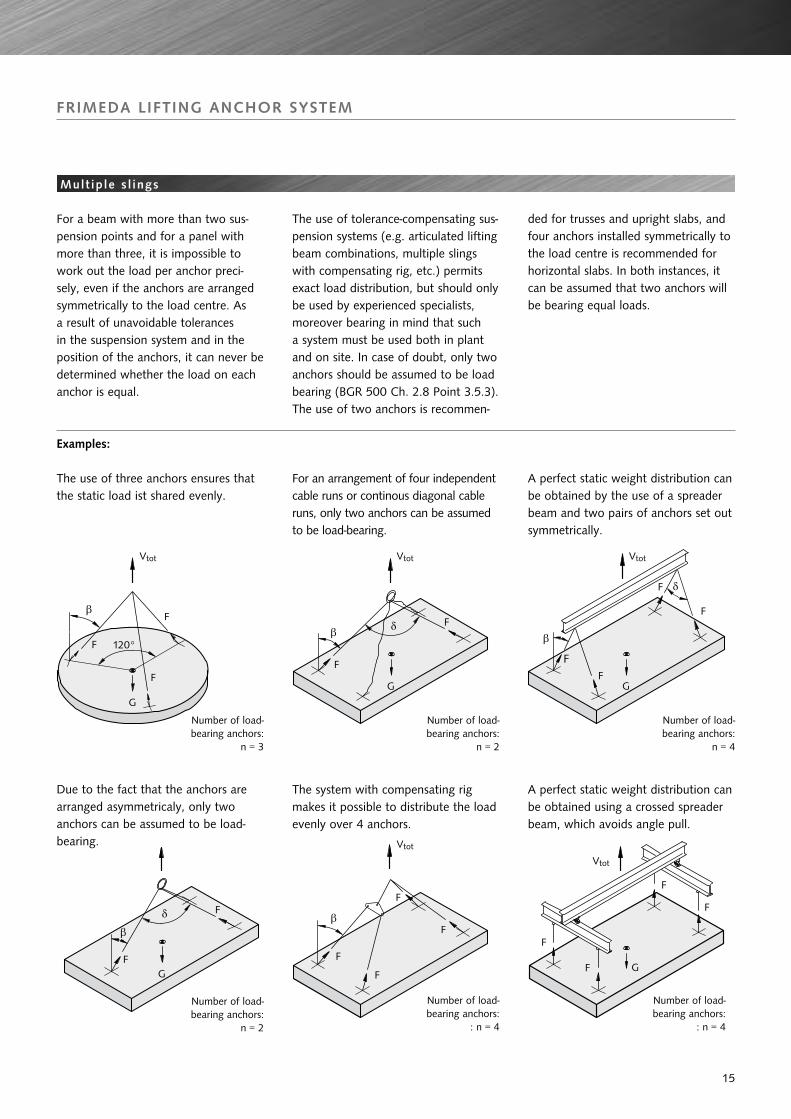
The use of three anchors ensures that the static load ist shared evenly.
For an arrangement of four independent cable runs or continous diagonal cable runs, only two anchors can be assumed to be load-bearing.
The system with compensating rig makes it possible to distribute the load evenly over 4 anchors.
A perfect static weight distribution can be obtained by the use of a spreader beam and two pairs of anchors set out symmetrically.
A perfect static weight distribution can be obtained using a crossed spreader beam, which avoids angle pull.
For a beam with more than two sus-pension points and for a panel with more than three, it is impossible to work out the load per anchor preci-sely, even if the anchors are arranged symmetrically to the load centre. As a result of unavoidable tolerances in the suspension system and in the position of the anchors, it can never be determined whether the load on each anchor is equal.
The use of tolerance-compensating sus-pension systems (e.g. articulated lifting beam combinations, multiple slings with compensating rig, etc.) permits exact load distribution, but should only be used by experienced specialists, moreover bearing in mind that such a system must be used both in plant and on site. In case of doubt, only two anchors should be assumed to be load bearing (BGR 500 Ch. 2.8 Point 3.5.3).The use of two anchors is recommen-
ded for trusses and upright slabs, and four anchors installed symmetrically to the load centre is recommended for horizontal slabs. In both instances, it can be assumed that two anchors will be bearing equal loads.
Due to the fact that the anchors are arranged asymmetricaly, only two anchors can be assumed to be load-bearing.
Number of load-bearing anchors:
n = 3
Number of load-bearing anchors:
n = 2
Number of load-bearing anchors:
: n = 4
Number of load-bearing anchors:
n = 4
Number of load-bearing anchors:
: n = 4
Vtot Vtot Vtot
Vtot
Vtot
Number of load-bearing anchors:
n = 2
15

Calculation parameters for this example
ExampleSlap unit
Manufacturing plantOn site
Lifting Transport
g Mass 10 t ( ∼ 100 kN) 10 t ( ∼ 100 kN)
A Mould area 20 m2 -
q Adhesion to formework 2 kN/m2 - -
f Lifting load coefficient - 1.1 1.4
z Cable angle factor 1.04 ( β = 15°) 1.41 ( β = 45°)
βw Concrete strenght 15 N/mm2 35 N/mm2
G
For dimensioning the anchor, a distinction can be made between the situation in the manufacturing plant and on the construction sites. Oversizing of anchors as a result of superimposition of all detrimental factors is avoided.
Example slab unit:Lifting, transporting in the plant and on site
Lifting at the plant:
F = ( G + q x A ) x z/n
Transport at the plant:
F = G x f x z/n
Transport on the constr. site:
F = G x f x z/n
Adhesion to formework
Lifting load
Dimensioning example s lab uni t
With 2 supporting anchors, the angled pull force F per an-chor is as follows:
F = (100kN + 2 kN/m2 x20 m2) x 1,04/2 = 72,8 kN
F = 100 kN x 1,1 x 1,04/2 = 57,2 kN
F = 100 kN x 1,4 x 1,41/2 = 98,7 kN
An anchor in the 10 t load range is just adequate.
If all detrimental factors were superimposed, the result would be
F = (100kN + 20m2 x 2 kN/m2 ) x 1,4 x 1,41/2 = 138 kN
e.g. an anchor in the load group 14 would have to be used.
The loads occurring on site are often higher than in the manufacturing plant as a result of greater cable spread and possibly higher lifting force coefficients. In this instance, it is beneficial that the concrete‘s strength is usually likewise higher, and that the anchor‘s load capacity in the concrete is thus higher.
In the above example, the result for a TPA-FS (see p. 20) would be as follows:
At the manufacturing plant (βW = 15 N/mm2, cable angle 15°):Angled pull 15° < 30°•full permissible load at angled pull, even with βW = 15N/mm2
On the construction site (βW = 35 N/mm2, cable angle 45°):Angled pull 45° > 30°•full permissible load at angled pull for concrete strength
of βW = 35 N/mm2 > 23 N/mm2, with angled pull reinforcement
FRIMEDA LIFTINg ANCHOR SySTEM
Dimensioning examples
16

Lifting and transporting at the manufacturing plant:
Concrete strength when lifted: βW ≥ 25N/mm2
Cable angle: b = 30°Cable angle factor: z = 1,16Lifting load coefficient (transporting) f = 1,1Lifting load coefficient (lifting) f = 1,0
Loads:Dead weight: G = ( 0,1 x 3,0 + 2 x 0,32 ) x 8,7 x 25 = 104,4 kNAdhesion to mould: Ha = 2 x G = 208,8 kNTotal load: Q = Ha + G = 313,2 kN
Load per anchor during lifting:F = 1,16 x 1,0 x ( 313,2 / 4 ) = 90,8 kN
Load per anchor during transporting:F = 1,16 x 1,1 x ( 104,4 / 4 ) = 33,3 kN
Anchor selected: TPA-FS 10,0-30( acc. to table page 21 ) Fperm, lifting 100 kN Fperm, transporting 100 kN
Lifting at the manufacturing plant and transporting on the constructions site
Concrete strength when lifting: βW≥15N/mm2
Adhesion to formwork: q = 1kN/m2
Lifting load coefficient of the crane: f = 1,1 (lifting at the plant) f = 1,3 (transporting on the site)
Loads:Dead weight: G = 0,16 x 7,0 x 2,5 x 25 = 70,0 kNAdhesion to formwork: Ha = 2,5 x 7,0 x 1 = 17,5 kNTotal load: Q = G + Ha = 87,5 kN
Load per anchor during lifting:F1 = 1,1 x ( 87,5 / 2 ) x 0,5 = 24,1 kN
Load per anchor during transporting:F1 = 1,3 x ( 70 / 2 ) = 45,5 kN
Anchor selected: TPA-FA 5,0-29(acc. to table page 28) Fperm, lifting 25kN > 24,1 kN Fperm, transporting 50kN > 45,5 kN
wall s lab
Structural reinforcement: no additional reinforcement required
Additional reinforcement for pull: Ø 16 l = 1500 mmTilting reinforcement: Ø 16 l = 1000 mm
FRIMEDA LIFTINg ANCHOR SySTEM
Dimensioning examples
π-s lab
All dimensions in cm
All dimensions in cm
17

Symbols used in this cataloge
Load direction Symbol
Central pull in direction of anchor axis
Transverse pull perpendicular to the anchor surface
Transverse pull parallel to the anchor surface
Angled pull, transverse component perpendicular to the anchor surface
Angled pull, transverse component parallel to the anchor surface
FRIMEDA LIFTINg ANCHOR SySTEM
Basic pr inc ip les for the anchor se lect ion tables
Spread anchors for la rge -area precast uni ts Spread anchors for th in -wal led preacast uni t
Basic principles for the load capacitiy tables Anchor ar rangement for th in -wal led uni ts
The values for loads and edge distances in the following tables have been calculated in accordance with the applicable regulations, a calculation process adapted to the anchors and corresponding trials.
Spread, erection and two hole anchors may only be installed in thin-walled elements with the flat steel at right-angles to the slab.
Minimum thickness of precast units
B = l + k + c
l = Anchor lengthk = Cover to anchor headc = Concrete cover acc. to DIN 1045-1
Incorrect Correct
When the load is towards the narrow edge (face end), a reinforce-ment for angled pull must be designed and installed in accordance with DIN 1045-1.
Link
Mesh reinforcement
18

Dimensions, Spread anchor TPA-FS
Designationmill finish
Order No.0070.010-
Designationhot-dip galvanised
Order No.0070.110-
Load group[t]
a[mm]
b[mm]
c[mm]
l[mm]
k[mm]
TPA-FS 0,7-11 00001 TPA-FS 0,7-11 FV 00032
2,5
30 14 5 110
10
TPA-FS 1,4-11 00002 TPA-FS 1,4-11 FV 00033 30 14 6 110
TPA-FS 1,4-16 00003 TPA-FS 1,4-16 FV 00034 30 14 6 160
TPA-FS 2,0-13 00004 TPA-FS 2,0-13 FV 00035 30 14 8 130
TPA-FS 2,0-16 00005 TPA-FS 2,0-16 FV 00036 30 14 8 160
TPA-FS 2,0-21 00006 TPA-FS 2,0-21 FV 00037 30 14 8 210
TPA-FS 2,5-15 00007 TPA-FS 2,5-15 FV 00038 30 14 10 150
TPA-FS 2,5-20 00008 TPA-FS 2,5-20 FV 00039 30 14 10 200
TPA-FS 2,5-25 00009 TPA-FS 2,5-25 FV 00040 30 14 10 250
TPA-FS 3,0-16 00010 TPA-FS 3,0-16 FV 00041
5,0
40 18 10 160
10
TPA-FS 3,0-20 00011 TPA-FS 3,0-20 FV 00042 40 18 10 200
TPA-FS 3,0-28 00012 TPA-FS 3,0-28 FV 00043 40 18 10 280
TPA-FS 4,0-18 00013 TPA-FS 4,0-18 FV 00044 40 18 12 180
TPA-FS 4,0-24 00014 TPA-FS 4,0-24 FV 00045 40 18 12 240
TPA-FS 4,0-32 00015 TPA-FS 4,0-32 FV 00046 40 18 12 320
TPA-FS 5,0-18 00016 TPA-FS 5,0-18 FV 00047 40 18 15 180
TPA-FS 5,0-24 00017 TPA-FS 5,0-24 FV 00048 40 18 15 240
TPA-FS 5,0-40 00018 TPA-FS 5,0-40 FV 00049 40 18 15 400
TPA-FS 7,5-26 00022 TPA-FS 7,5-26 FV 00053
10,0
60 26 16 260
15
TPA-FS 7,5-30 00023 TPA-FS 7,5-30 FV 00054 60 26 16 300
TPA-FS 7,5-42 00024 TPA-FS 7,5-42 FV 00055 60 26 16 420
TPA-FS 10,0-30 00025 TPA-FS 10,0-30 FV 00056 60 26 20 300
TPA-FS 10,0-37 00026 TPA-FS 10,0-37 FV 00057 60 26 20 370
TPA-FS 10,0-52 00027 TPA-FS 10,0-52 FV 00058 60 26 20 520
TPA-FS 14,0-37 00028 TPA-FS 14,0-37 FV 00059
26,0
80 35 20 370
15TPA-FS 14,0-46 00029 TPA-FS 14,0-46 FV 00060 80 35 20 460
TPA-FS 22,0-50 00030 TPA-FS 22,0-50 FV 00062 90 35 28 500
TPA-FS 22,0-62 00031 TPA-FS 22,0-62 FV 00063 90 35 28 620
Anchor d imens ions
FRIMEDA LIFTINg ANCHOR SySTEM
Spread anchor TPA-FS
The spread anchor is very versatile. It provides an efficient anchorage in both thin panels and slabs. For special ap-plications additional reinforcement can be combined with the spread anchor by utilising the extra hole.
19
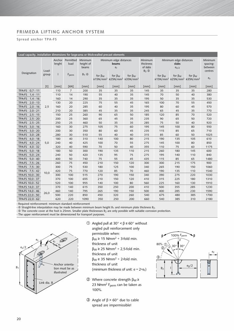
Load capacity, installation dimensions for large-area or thick-walled precast elements
DesignationLoad-group
Anchor lenght
l
Permitted load
Fperm
Minimum height of beams
B1
Minimum edge distancesbeams
er
Minimum thickness of slabsB2
Minimum edge distancesslabsez/2
Minimum spacing-between centres
ezfor βW
≥15N/mm2for βW
≥25N/mm2for βW
≥35N/mm2for βW
≥15N/mm2for βW
≥25N/mm2for βW
≥35N/mm2
[t] [mm] [kN] [mm] [mm] [mm] [mm] [mm] [mm] [mm] [mm] [mm]
TPA-FS 0,7 - 11
2,5
110 7 200 35 35 35 145 35 35 35 280TPA-FS 1,4 - 11 110 14 190 55 40 35 145 70 50 40 380TPA-FS 1,4 - 16 160 14 290 35 35 35 195 50 35 35 530TPA-FS 2,0 - 13 130 20 225 75 55 45 165 100 70 55 450TPA-FS 2,0 - 16 160 20 285 60 40 35 195 80 60 45 570TPA-FS 2,0 - 21 210 20 385 45 35 35 245 65 45 35 770TPA-FS 2,5 - 15 150 25 260 90 65 50 185 120 85 70 520TPA-FS 2,5 - 20 200 25 360 65 45 35 235 90 65 50 720TPA-FS 2,5 - 25 250 25 460 50 35 35 285 75 50 40 920TPA-FS 3,0 - 16
5,0
160 30 275 105 75 60 195 145 100 80 550TPA-FS 3,0 - 20 200 30 350 80 60 45 235 115 85 65 710TPA-FS 3,0 - 28 280 30 510 55 40 40 315 85 60 50 1025TPA-FS 4,0 - 18 180 40 310 140 100 80 215 190 135 105 610TPA-FS 4,0 - 24 240 40 425 100 70 55 275 145 100 80 850TPA-FS 4,0 - 32 320 40 590 70 50 40 355 110 75 60 1175TPA-FS 5,0 - 18 180 50 300 190 135 110 215 260 180 145 600TPA-FS 5,0 - 24 240 50 420 135 95 75 275 195 140 110 840TPA-FS 5,0 - 40 400 50 740 75 55 45 435 115 85 65 1480TPA-FS 7,5 - 26
10,0
260 75 450 210 150 120 300 300 215 175 900TPA-FS 7,5 - 30 300 75 530 180 125 100 340 265 190 150 1060TPA-FS 7,5 - 42 420 75 770 120 85 70 460 190 135 110 1540TPA-FS 10,0 - 30 300 100 515 270 190 150 340 390 275 220 1030TPA-FS 10,0 - 37 370 100 655 210 150 120 410 315 225 180 1310TPA-FS 10,0 - 52 520 100 955 140 100 80 560 225 160 130 1910TPA-FS 14,0 - 37
26,0
370 140 615 350 250 200 410 500 355 285 1230TPA-FS 14,0 - 46 460 140 795 265 190 150 500 400 285 230 1590TPA-FS 22,0 - 50 500 220 850 450 320 260 540 675 480 385 1700TPA-FS 22,0 - 62 620 220 1090 350 250 200 660 540 385 310 2180
- Required reinforcement: minimum standard reinforcement- Straight-line interpolation may be made between minimum beam height B1 and minimum plate thickness B2.- The concrete cover at the foot is 25mm. Smaller plate thicknesses B2 are only possible with suitable corrosion protection.- The upper reinforcement must be dimensioned for transport purposes.
FRIMEDA LIFTINg ANCHOR SySTEM
Spread anchor TPA-FS
À Angled pull at 30° < β ≤ 60° without angled pull reinforcement only permissible when: βW ≥ 15 N/mm2 + 3-fold min. thickness of unit βW ≥ 25 N/mm2 + 2,5-fold min. thickness of unit βW ≥ 35 N/mm2 + 2-fold min. thickness of unit (minimum thickness of unit: e = 2×er)
Where concrete strength βW ≥ 23 N/mm2 Fperm can be taken as 100%.
Angle of β > 60° due to cable spread are impermissible!
Fperm
Link dia. 8
Anchor orienta-tion must be as illustrated
20

Load capacity, installation dimensions Concrete strength βw ≥ 15 N/mm2
Designation Load group
Minimum distances from edge and between centres
for βW ≥ 15N/mm2
Tilting and turning reinforcementPermitted load
er ez ds ls À
Lifting Lifting Tilting
[t] [mm] [mm] [mm] [mm] [kN] [kN] [kN]
TPA-FS 0,7 - 11
2,5
100 700 dia. 8 600 7 5.6 3.5
TPA-FS 1,4 - 16 100 700 dia. 10 700 14 11.2 7
TPA-FS 2,0 - 21 100 800 dia. 10 750 20 16 10
TPA-FS 2,5 - 25 100 875 dia. 12 800 25 20 12.5
TPA-FS 3,0 - 28
5,0
150 950 dia. 12 850 30 24 15
TPA-FS 4,0 - 32 150 1050 dia. 14 950 40 32 20
TPA-FS 5,0 - 40 150 1435 dia. 16 1000 50 40 25
TPA-FS 7,5 - 42 10,0
250 1470 dia. 20 1200 75 60 37.5
TPA-FS 10,0 - 52 300 1820 dia. 20 1500 100 80 50
TPA-FS 14,0 - 46 26,0
525 1800 dia. 25 1800 140 112 70
TPA-FS 22,0 - 62 710 2200 dia. 28 1800 220 176 110
À ls = Length before bending reinforcement steel For concrete strength βW ≥ 23 N/mm2 is 100% of load permitted.- Required reinforcement: minimum standard reinforcement
FRIMEDA LIFTINg ANCHOR SySTEM
Spread anchor TPA-FS
Load capac i ty , insta l la t ion d imens ions for t i l t ing and turn ing
The horizontal legs of the tilting and turning reinforcement are located directly within the outermost position of the reinforced area.
Reinforcement steel:Yield strength 500 N/mm2,Tensile strength 550 N/mm2
spacing to the next anchor
Anchor orienta-tion must be as illustrated
ds
ls Àstraight length
≤ 90° h = depends on the component thickness
21

Load capacity and installation dimensions
Designation Load group
Anchor length
l
Spacing between anchor centres
min. ez
Min. thickness of precast unit2 x er
100% FpermPull
(β ≤ 30°)
80% FpermAngled pull(β > 30°)
where βW≥ 15 N/mm2
where βW≥ 25 N/mm2
where βW≥ 35 N/mm2
[t] [mm] [mm] [mm] [mm] [mm] [kN] [kN]
TPA-FS 0,7 - 11
2,5
110 330 60 60 60 7 5.6
TPA-FS 1,4 - 11 110 330 75 60 60 14 11.2
TPA-FS 1,4 - 16 160 480 75 60 60 14 11.2
TPA-FS 2,0 - 13 130 390 100 80 70 20 16
TPA-FS 2,0 - 16 160 480 100 80 70 20 16
TPA-FS 2,0 - 21 210 630 100 80 70 20 16
TPA-FS 2,5 - 15 150 450 120 90 80 25 20
TPA-FS 2,5 - 20 200 600 120 90 80 25 20
TPA-FS 2,5 - 25 250 750 120 90 80 25 20
TPA-FS 3,0 - 16
5,0
160 480 160 90 80 30 24
TPA-FS 3,0 - 20 200 600 120 90 80 30 24
TPA-FS 3,0 - 28 280 840 120 90 80 30 24
TPA-FS 4,0 - 18 180 540 210 130 100 40 32
TPA-FS 4,0 - 24 240 720 150 115 100 40 32
TPA-FS 4,0 - 32 320 960 150 115 100 40 32
TPA-FS 5,0 - 18 180 540 350 210 150 50 40
TPA-FS 5,0 - 24 240 720 180 140 120 50 40
TPA-FS 5,0 - 40 400 1200 180 140 120 50 40
TPA-FS 7,5 - 26
10,0
260 780 340 200 150 75 60
TPA-FS 7,5 - 30 300 900 240 150 130 75 60
TPA-FS 7,5 - 42 420 1260 195 150 130 75 60
TPA-FS 10,0 - 30 300 900 450 270 190 100 80
TPA-FS 10,0 - 37 370 1110 270 190 160 100 80
TPA-FS 10,0 - 52 520 1560 245 190 160 100 80
TPA-FS 14,0 - 37
26,0
370 1110 610 360 260 140 112
TPA-FS 14,0 - 46 460 1380 350 210 165 140 112
TPA-FS 22,0 - 50 500 1500 760 460 330 220 176
TPA-FS 22,0 - 62 620 1860 450 270 230 220 176
- Observe the reinforcement data on table page 23.- Smaller wall thicknesses are possible in the case of reverse reinforcement of the release head. However, this means reinforced concrete with a cracked tension zone.
FRIMEDA LIFTINg ANCHOR SySTEM
Spread anchor TPA-FS
Load capac i ty , insta l la t ion d imens ions for th in -wal led precast e lements
À Angled pull at 30° < β ≤ 60° without angled pull reinforcement only permissible when: βW ≥ 15 N/mm2 + 3-fold min. thickness of unit βW ≥ 25 N/mm2 + 2,5-fold min. thickness of unit βW ≥ 35 N/mm2 + 2-fold min. thickness of unit (Minimum thickness of unit: e = 2 × er)
Where concrete strength βW ≥ 23 N/mm2 Fperm can be taken as 100%.
Angle of β > 60° due to cable spread are impermissible!
without angled pull reinforcement with angled pull reimnforcement
Position the angled pull reinforcementas closely to the recess former as possible
Fperm Fperm
Fperm Fperm Fperm
22

Reinforcement of thin precast concrete elements Concrete strength βw ≥ 15 N/mm2
Load group Load range
Pull β ≤ 30° Angled pull β > 30°
Mesh reinf. both sides crosswise *
Slot-in link *
ds x ls
Edge reinforcement *
Mesh reinf.* both sides crosswise
Slot-in link *
ds x ls
Edge reinforcement *
ÀAngle pull
reinforcement *
ds1 x ls1[t] [t] [mm2/m] [mm] [mm] [mm2/m] [mm] [mm] [mm]
2,5
0,7 131 construktive construktive 131 4 dia. 6 x 300 dia. 8 dia. 6 x 450
1,4 131 2 dia. 6 x 400 construktive 131 4 dia. 6 x 400 dia. 8 dia. 6 x 900
2,0 131 2 dia. 6 x 500 construktive 131 4 dia. 6 x 500 dia. 8 dia. 8 x 950
2,5 131 2 dia. 8 x 600 construktive 131 4 dia. 8 x 600 dia. 10 dia. 8 x 1200
5,03,0 131 2 dia. 8 x 700 construktive 131 4 dia. 8 x 700 dia. 10 dia. 10 x 1150
4,0 131 2 dia. 8 x 800 construktive 131 4 dia. 8 x 800 dia. 12 dia. 10 x 1500 5,0 131 2 dia. 10 x 800 construktive 131 4 dia. 10 x 800 dia. 12 dia. 12 x 1550
10,07,5 188 4 dia. 10 x 800 dia. 10 188 4 dia. 10 x 800 dia. 12 dia. 14 x 2000
10,0 188 6 dia. 10 x 1000 dia. 12 188 6 dia. 10 x 1000 dia. 14 dia. 16 x 2300
26,014,0 257 6 dia. 10 x 1000 dia. 14 257 8 dia. 10 x 1000 dia. 14 dia. 20 x 2600
22,0 257 8 dia. 10 x 1200 dia. 14 257 8 dia. 10 x 1200 dia. 16 dia. 28 x 3450
À No angled pull reinforcement is needed • forconcretestrengthofβW 15 N/mm2 + 3-fold minimum thickness of units • forconcretestrengthofβW 25 N/mm2 + 2,5-fold minimum thickness of units * Yield strength 500 N/mm2
• forconcretestrengthofβW 25 N/mm2 + 2-fold minimum thickness of units Tensile strength 550 N/mm2
FRIMEDA LIFTINg ANCHOR SySTEM
Spread anchor TPA-FS
Reinforcement at anchor zone for th in -wal led precast e lements
Reinforced zone≥ 3-fold anchor length d
Edge reinforcement
Always insert angled pull linkopposite the direction of the load
Leng
th o
f sl
ot-in
link
Slot-in link, (positioned as close to anchor as possible)
Mesh rei
nforcement
Angled pull reinforcement ls1 = Overall length(approx. 2 x length of leg)
23

Dimensions, Two hole anchor TPA-FZ
Designationmill finish
Order No.0070.020-
Load group[t]
a[mm]
b[mm]
c[mm]
l[mm]
k[mm]
TPA-FZ 1,4- 9 00002
2,5
30 14 6 90
10TPA-FZ 2,0- 9 00003 30 14 8 90
TPA-FZ 2,5- 9 00004 30 14 10 90
TPA-FZ 3,0-12 00005
5,0
40 18 10 120
10TPA-FZ 4,0-12 00006 40 18 12 120
TPA-FZ 5,0-12 00007 40 18 15 120
TPA-FZ 7,5-16 0000910,0
60 26 16 16015
TPA-FZ 10,0-17 00010 60 30 20 165
TPA-FZ 14,0-24 00011
26,0
80 35 20 240
15TPA-FZ 22,0-30 00013 90 35 28 300
TPA-FZ 26,0-30 00012 120 65 30 300
Designationhot-dip galvanised
Order No.0070.110-
Load group[t]
a[mm]
b[mm]
c[mm]
l[mm]
k[mm]
TPA-FZ 1,4- 9 FV 00064
2,5
30 14 6 90
10TPA-FZ 2,0- 9 FV 00065 30 14 8 90
TPA-FZ 2,5- 9 FV 00066 30 14 10 90
TPA-FZ 3,0-12 FV 00067
5,0
40 18 10 120
10TPA-FZ 4,0-12 FV 00068 40 18 12 120
TPA-FZ 5,0-12 FV 00069 40 18 15 120
TPA-FZ 7,5-16 FV 0007110,0
60 26 16 16015
TPA-FZ 10,0-17 FV 00072 60 30 20 165
TPA-FZ 14,0-24 FV 00073
26,0
80 35 20 240
15TPA-FZ 22,0-30 FV 00075 90 35 28 300
TPA-FZ 26,0-30 FV 00074 120 65 30 300
The head of the two hole anchor is identical to the head of the spread anchor. The anchorage in concrete is achieved by means of a reinforcement tail. Longer anchors with additional holes can be produced on request.
FRIMEDA LIFTINg ANCHOR SySTEM
Two hole anchor TPA-FZ
Anchor d imens ions
24

Load capacity, installation dimensions TPA-FZ Concrete strength βw ≥ 15 N/mm22
Designation Load group
Anchor lenght
l
Spacing between anchor centres
ez
Minimum thickness of precast unit
2 x er
100% FpermPull
(β ≤ 30°)
80% FpermAngled pull(β > 30°)
[t] [mm] [mm] [mm] [kN] [kN]
TPA-FZ 1,4- 9
2,5
90 500 80 14 11.2
TPA-FZ 2,0- 9 90 600 90 20 16
TPA-FZ 2,5- 9 90 600 100 25 20
TPA-FZ 3,0-12
5,0
120 650 100 30 24
TPA-FZ 4,0-12 120 700 110 40 32
TPA-FZ 5,0-12 120 750 120 50 40
TPA-FZ 7,5-16 10,0
160 1200 130 75 60
TPA-FZ 10,0-17 165 1200 140 100 80
TPA-FZ 14,0-24
26,0
240 1500 160 140 112
TPA-FZ 22,0-30 300 1500 180 220 176
TPA-FZ 26,0-30 300 1500 200 260 208
Observe the reinforcement data on table page 26.
FRIMEDA LIFTINg ANCHOR SySTEM
Two hole anchor TPA-FZ
Load capac i ty , insta l la t ion d imens ions
À Angled pull at 30° < β ≤ 60° without angled pull reinforcement only permissible when: βW ≥ 15 N/mm2 + 3-fold min. thickness of unit βW ≥ 25 N/mm2 + 2,5-fold min. thickness of unit βW ≥ 35 N/mm2 + 2-fold min. thickness of unit (minimum thickness of unit: e = 2 × er)
Where concrete strength βW ≥ 23 N/mm2 Fperm can be taken as 100%.
Angle of β > 60° due to cable spread are impermissible!
without angled pull reinforcement with angled pull reinforcement
Position the angled pull reinforcement as closely to the recess former as possible
Fperm
Fperm
Fperm
Fperm
Fperm
25

Reinforcement Concrete strength βw ≥ 15 N/mm2
Designation
Load group
Pull ( β ≤ 30° ) Angled pull ( β > 30° )
Mesh reinf.
both sides crosswise*
Slot-in links *
ds x ls
Edge reinf.*
Add. reinf. for pull
ds2 x ls2both sides
Mesh reinf.
both sides crosswise*
Slot-in links *
ds x ls
Edge reinf.*
Add. reinf. for
pull
ds2 x ls2
ÀAngled Pull
reinf.
ds1 x ls1
[t] [mm2/m] [mm] [mm] [mm] [mm2/m] [mm] [mm] [mm] [mm]
TPA-FZ 1,4- 9
2,5
131 2 dia. 6 x 400 constructive 1 dia. 10 x 650 131 4 dia. 6 x 400 dia. 8 1 dia. 10 x 650 dia. 6 x 900
TPA-FZ 2,0- 9 131 2 dia. 6 x 500 constructive 1 dia. 12 x 800 131 4 dia. 6 x 500 dia. 8 1 dia. 10 x 800 dia. 8 x 950
TPA-FZ 2,5- 9 131 2 dia. 8 x 600 constructive 1 dia. 12 x 1000 131 4 dia. 8 x 600 dia. 10 1 dia. 12 x 1000 dia. 8 x 1200
TPA-FZ 3,0-12 5,0
131 2 dia. 8 x 700 constructive 1 dia. 14 x 1000 131 4 dia. 8 x 700 dia. 10 1 dia. 14 x 1000 dia. 10 x 1150
TPA-FZ 4,0-12 131 2 dia. 8 x 700 constructive 1 dia. 16 x 1200 131 4 dia. 8 x 800 dia. 12 1 dia. 16 x 1200 dia. 10 x 1500 TPA-FZ 5,0-12 131 2 dia. 8 x 800 constructive 1 dia. 16 x 1500 131 4 dia. 10 x 800 dia. 12 1 dia. 16 x 1500 dia. 12 x 1550 TPA-FZ 7,5-16
10,0131 2 dia. 10 x 800 dia. 10 1 dia. 20 x 1750 131 4 dia. 10 x 800 dia. 12 1 dia. 20 x 1750 dia. 14 x 2000
TPA-FZ 10,0-17 131 4 dia. 10 x 800 dia. 12 1 dia. 25 x 1850 131 6 dia. 10 x 1000 dia. 14 1 dia. 25 x 1850 dia. 16 x 2300
TPA-FZ 14,0-24
26,0
131 4 dia. 10 x 1000 dia. 14 1 dia. 28 x 2350 131 8 dia. 10 x 1000 dia. 14 1 dia. 28 x 2350 dia. 20 x 2600
TPA-FZ 22,0-30 131 4 dia. 12 x 1200 dia. 14 1 dia. 28 x 3000 131 8 dia. 10 x 1200 dia. 16 1 dia. 28 x 3000 dia. 25 x 3000
TPA-FZ 26,0-30 131 6 dia. 12 x 1200 dia. 14 2 dia. 28 x 3050 131 8 dia. 12 x 1200 dia. 16 2 dia. 28 x 3050 dia. 28 x 3450
À No angled pull reinforcement is needed: • forconcretestrengthofvonβW ≥ 15 N/mm2 + 3-fold minimum thickness of units • forconcretestrengthofvonβW ≥ 25 N/mm2 + 2,5-fold minimum thickness of units • forconcretestrengthofvonβW ≥ 35 N/mm2 + 2-fold minimum thickness of units For other concrete strengths, the length Ls2 of the additional reinforcement tail for pull may be reduced in relation to the permissible bond stress ( βW = 25 N/mm2 : x 0,8; βW = 35 N/mm2 : x 0,65 )- Please consult us if the concrete strength is lower or if lightweight concrete is used.- * Yield strength: 500 N/mm2, tensile strength: 550 N/mm2
FRIMEDA LIFTINg ANCHOR SySTEM
Two hole anchor TPA-FZ
Reinforcement in anchor zone
Reinforced zone≥ 3-fold anchor length d
Edge reinforcement
Leng
th o
f sl
ot-in
link
l
Slot-in link, (positioned as closely to anchor as possible)
Mesh rei
nforcement
Angled pull reinforcementas close as possible to recess former
ls1 = Overall length(approx. 2 x length of leg)
Additional reinforcement tail for pull
Additional reinforcement tail for pull
26

Dimensions, Erection anchor TPA-FA
Designationmill finish
Order No.0070.030-
Designationhot-dip galvanised
Order No.0070.110-
Load group[t]
a[mm]
c[mm]
l[mm]
g[mm]
k[mm]
k1[mm]
TPA-FA 1,4- 20 00001 TPA-FA 1,4- 20 FV 000012,5
55 6 200 4510 5
TPA-FA 2,5- 23 00002 TPA-FA 2,5- 23 FV 00002 55 10 230 45
TPA-FA 4,0-27 00003 TPA-FA 4,0-27 FV 000035,0
70 12 270 7010 5
TPA-FA 5,0-29 00004 TPA-FA 5,0-29 FV 00004 70 15 290 70
TPA-FA 7,5-32 00005 TPA-FA 7,5-32 FV 0000510,0
95 15 320 9015 6
TPA-FA 10,0-39 00006 TPA-FA 10,0-39 FV 00006 95 20 390 90
TPA-FA 12,5-50 00007 TPA-FA 12,5-50 FV 00007
26,0
148 20 500 90
15 9TPA-FA 17,0-50 00008 TPA-FA 17,0-50 FV 00008 148 25 500 90
TPA-FA 22,0-50 00009 TPA-FA 22,0-50 FV 00009 148 30 500 90
Dimensions, Unilateral erection anchor TPA-FE
Designationmill finish
Order No.0070.040-
Designationhot-dip galvanised
Order No.0070.110-
Load group[t]
a[mm]
c[mm]
l[mm]
g[mm]
k[mm]
k1[mm]
TPA-FE 1,4- 20 00001 TPA-FE 1,4- 20 FV 000102,5
40 6 200 42.210 5
TPA-FE 2,5- 23 00002 TPA-FE 2,5- 23 FV 00011 40 10 230 42.5
TPA-FE 4,0-27 00003 TPA-FE 4,0-27 FV 000125,0
55 12 270 50.510 5
TPA-FE 5,0-29 00004 TPA-FE 5,0-29 FV 00013 55 15 290 50.5
TPA-FE 7,5-32 00005 TPA-FE 7,5-32 FV 0001410,0
80 15 320 78,015 6
TPA-FE 10,0-39 00006 TPA-FE 10,0-39 FV 00015 80 20 390 78,0
TPA-FE 12,5-50 00007 TPA-FE 12,5-50 FV 00016
26,0
115 20 500 88.5
15 9TPA-FE 17,0-50 00008 TPA-FE 17,0-50 FV 00017 115 25 500 88.5
TPA-FE 22,0-50 00009 TPA-FE 22,0-50 FV 00018 115 30 500 88.5
FRIMEDA LIFTINg ANCHOR SySTEM
Erect ion anchor TPA-FA / Uni la tera l erect ion anchor TPA-FE
Anchor d imens ions TPA-FA / TPA-FE
Load range 1,4t-17,0t
Load range 22,0t
Load range 1,4t-17,0t
Load range 22,0t
The special shaped anchor head means that that the pitching/turning loads are taken by the anchor and not to the concrete. This helps to prevent spalling of the concrete. The anchors are notched to assist with the placement of additional reinforce-ment required in the pitching/turning operation.
In contrast to the erection anchor TPA-FA, the TPA-FE can only be subjected to load in one direction. Its shape makes it particularly suitable for thin components. A semi-circular notch is provided for fitting of the turning reinforcement.
27
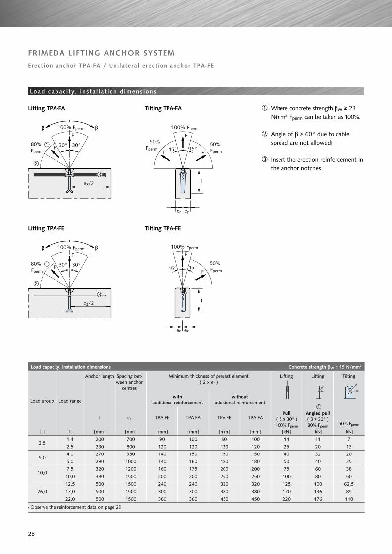
Load capacity, installation dimensions Concrete strength βw ≥ 15 N/mm2
Load group Load range
Anchor length Spacing bet-ween anchor
centres
Minimum thickness of precast element( 2 x er )
Lifting
Pull( β ≤ 30° )100% Fperm
Lifting
ÀAngled pull( β > 30° )80% Fperm
Tilting
50% Fperm
with additional reinforcement
without additional reinforcement
l ez TPA-FE TPA-FA TPA-FE TPA-FA
[t] [t] [mm] [mm] [mm] [mm] [mm] [mm] [kN] [kN] [kN]
2,51,4 200 700 90 100 90 100 14 11 7
2,5 230 800 120 120 120 120 25 20 13
5,04,0 270 950 140 150 150 150 40 32 20
5,0 290 1000 140 160 180 180 50 40 25
10,07,5 320 1200 160 175 200 200 75 60 38
10,0 390 1500 200 200 250 250 100 80 50
26,0
12,5 500 1500 240 240 320 320 125 100 62,5
17,0 500 1500 300 300 380 380 170 136 85
22,0 500 1500 360 360 450 450 220 176 110
- Observe the reinforcement data on page 29.
FRIMEDA LIFTINg ANCHOR SySTEM
Erect ion anchor TPA-FA / Uni la tera l erect ion anchor TPA-FE
Load capac i ty , insta l la t ion d imens ions
À Where concrete strength βW ≥ 23 N/mm2 Fperm can be taken as 100%.
Angle of β > 60° due to cable spread are not allowed!
Insert the erection reinforcement in the anchor notches.
Lifting TPA-FA Tilting TPA-FA
Lifting TPA-FE Tilting TPA-FE
Fperm Fperm
Fperm FpermFperm
Fperm
Fperm
Fperm
Fperm
28

Reinforcement of thin-walled concrete precast unit Concrete strength βw ≥ 15 N/mm2
Load group Load rateTilting
reinforcementds1 x ls1 À
Additional reinforcement for pull
ds2 x ls2
[t] [t] [mm] [mm]
2,51,4 dia. 10 x 700 dia. 10 x 650
2,5 dia. 12 x 800 dia. 12 x 1000
5,04,0 dia. 14 x 950 dia. 16 x 1200
5,0 dia. 16 x 1000 dia. 16 x 1500
10,07,5 dia. 20 x 1200 dia. 20 x 1750
10,0 dia. 20 x 1500 dia. 20 x 1900
26,0
12,5 dia. 25 x 1500 dia. 25 x 2200
17,0 dia. 25 x 1800 dia. 28 x 2500
22,0 dia. 25 x 1800 dia. 28 x 3000
À ls1 = Length before bending reinforcement steel *For other concrete strength, the length ls1 of the erecting reinforcement may be reduced in relation to the permitted composite stresses * Yield strength: 500 N/mm2
(βW = 25 N/mm2 : x 0,8; βW = 35 N/mm2 : x 0,65) * Tensile strength: 550 N/mm2
TPA-FA TPA-FE
The horizontal legs of the tilting and turning reinforcement are located directly within the outermost position of the reinforced area.Tilting reinforcement on both sides also acts as angled pull reinforcement. No additional angled pull reinforce-ment is required.
without additional reinforcement for pull:Meshes, slot-in links and edge rein-forcement as for TPA-FS.
with additional reinforcement for pull:Meshes, slot-in links and edge rein-forcement as for TPA-FZ.
FRIMEDA LIFTINg ANCHOR SySTEM
Erect ion anchor TPA-FA / Uni la tera l erect ion anchor TPA-FE
Reinforcement in anchor zone
Bending radius acc. to DIN 1045-1.
Additional reinforcement for pull
Spacing to the next anchor
Spacing to the next anchor
ds2
ls2
≤30°
ds1
ls1 Àstraight length
≤ 90° h = depends on the component thickness
Anchor orienta-tion must be as illustrated
Anchor orienta-tion must be as illustrated
29
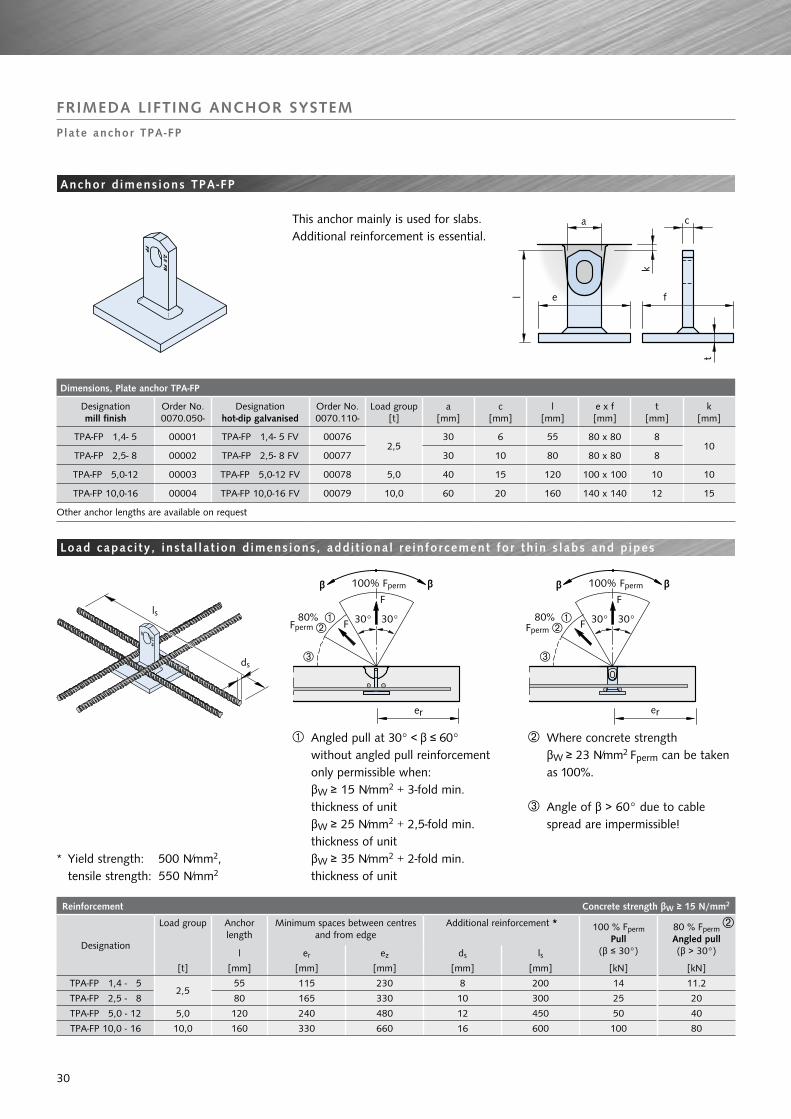
Dimensions, Plate anchor TPA-FP
Designationmill finish
Order No.0070.050-
Designationhot-dip galvanised
Order No.0070.110-
Load group[t]
a[mm]
c[mm]
l[mm]
e x f[mm]
t[mm]
k[mm]
TPA-FP 1,4- 5 00001 TPA-FP 1,4- 5 FV 000762,5
30 6 55 80 x 80 810
TPA-FP 2,5- 8 00002 TPA-FP 2,5- 8 FV 00077 30 10 80 80 x 80 8
TPA-FP 5,0-12 00003 TPA-FP 5,0-12 FV 00078 5,0 40 15 120 100 x 100 10 10
TPA-FP 10,0-16 00004 TPA-FP 10,0-16 FV 00079 10,0 60 20 160 140 x 140 12 15
Other anchor lengths are available on request
Reinforcement Concrete strength βw ≥ 15 N/mm2
Designation
Load group Anchor length
l
Minimum spaces between centres and from edge
Additional reinforcement * 100 % Fperm
Pull(β ≤ 30°)
80 % FpermAngled pull(β > 30°)er ez ds ls
[t] [mm] [mm] [mm] [mm] [mm] [kN] [kN]
TPA-FP 1,4 - 5 2,5
55 115 230 8 200 14 11.2
TPA-FP 2,5 - 8 80 165 330 10 300 25 20
TPA-FP 5,0 - 12 5,0 120 240 480 12 450 50 40
TPA-FP 10,0 - 16 10,0 160 330 660 16 600 100 80
FRIMEDA LIFTINg ANCHOR SySTEM
Plate anchor TPA-FP
Anchor d imens ions TPA-FP
This anchor mainly is used for slabs. Additional reinforcement is essential.
Load capac i ty , insta l la t ion d imens ions, addi t ional re inforcement for th in s labs and p ipes
À Angled pull at 30° < β ≤ 60° without angled pull reinforcement only permissible when: βW ≥ 15 N/mm2 + 3-fold min. thickness of unit βW ≥ 25 N/mm2 + 2,5-fold min. thickness of unit βW ≥ 35 N/mm2 + 2-fold min. thickness of unit
Where concrete strength βW ≥ 23 N/mm2 Fperm can be taken as 100%.
Angle of β > 60° due to cable spread are impermissible!
* Yield strength: 500 N/mm2, tensile strength: 550 N/mm2
Fperm
Fperm Fperm
Fperm
ls
ds
30

Dimensions, Flat foot anchor TPA-FF
Designationmill finish
Order No.0070.070-
Load group[t]
a[mm]
c[mm]
l[mm]
e[mm]
k[mm]
TPA-FF 0,7- 6 00001
2,5
30 5 65 70
10TPA-FF 1,4- 6 00002 30 6 65 70
TPA-FF 2,0- 7 00003 30 8 70 80
TPA-FF 2,5- 7 00004 30 10 75 94
TPA-FF 3,0- 9 00005
5,0
40 10 90 100
10TPA-FF 4,0-11 00006 40 12 110 100
TPA-FF 5,0-12 00007 40 15 125 105
TPA-FF 7,5-17 0000910,0
60 16 170 12015
TPA-FF 10,0-20 00010 60 20 200 120
TPA-FF 12,5-22 00011
26,0
80 16 220 200
15TPA-FF 17,0-27 00012 80 20 270 200
TPA-FF 22,0-31 00013 90 28 310 200
Designationhot-dip galvanised
Order No.0070.110-
Load group[t]
a[mm]
c[mm]
l[mm]
e[mm]
k[mm]
TPA-FF 0,7- 6 FV 00019
2,5
30 5 65 70
10TPA-FF 1,4- 6 FV 00020 30 6 65 70
TPA-FF 2,0- 7 FV 00021 30 8 70 80
TPA-FF 2,5- 7 FV 00022 30 10 75 94
TPA-FF 3,0- 9 FV 00023
5,0
40 10 90 100
10TPA-FF 4,0-11 FV 00024 40 12 110 100
TPA-FF 5,0-12 FV 00025 40 15 125 105
TPA-FF 7,5-17 FV 0002710,0
60 16 170 12015
TPA-FF 10,0-20 FV 00028 60 20 200 120
TPA-FF 12,5-22 FV 00029
26,0
80 16 220 200
15TPA-FF 17,0-27 FV 00030 80 20 270 200
TPA-FF 22,0-31 FV 00031 90 28 310 200
Other anchor lengths are available on request.
FRIMEDA LIFTINg ANCHOR SySTEM
Flat foot anchor TPA-FF
Anchor d imens ions TPA-FF
This anchor is an alternative to the plate anchor TPA-FP. The main use is in elements with a concrete strength at lifting in excess of 20 N/mm2.
Load range 2,5-5,0
Load range 10,0-26,0
31

Reinforcement in anchor zone Concrete strength βw ≥ 15 N/mm2
DesignationLoad group
Anchor length
Minimum thickness of
element
Minimum distance between centres and from edge
Additional reinforcement * Permitted loadCentrical, angled and transversal pullat concrete strength βW when lifted
l B er ez ds ls ≥15 N/mm2 ≥25 N/mm2 ≥35 N/mm2
[t] [mm] [mm] [mm] [mm] [mm] [mm] [kN] [kN] [kN]
TPA-FF 0,7 - 6
2,5
65 95 À 140 280 8 200 7 7 7
TPA-FF 1,4 - 6 65 95 À 140 280 8 250 14 14 14
TPA-FF 2,0 - 7 70 100 À 150 300 8 300 18 20 20
TPA-FF 2,5 - 7 75 105 À 160 320 8 300 20 25 25
TPA-FF 3,0 - 9
5,0
90 120 190 380 10 400 28 30 30
TPA-FF 4,0 - 11 110 140 230 460 12 450 37 40 40
TPA-FF 5,0 - 12 125 160 260 520 12 500 44 50 50
TPA-FF 7,5 - 17 10,0
170 215 340 680 14 600 54.6 70.4 75
TPA-FF 10,0 - 20 200 245 400 800 14 600 75.5 100 100
TPA-FF 12,5 - 22
26,0
220 265 440 880 16 750 88.5 125 125
TPA-FF 17,0 - 27 270 315 540 1080 16 900 120.3 170 170
TPA-FF 22,0 - 31 310 355 620 1240 20 1100 148 220 220
À If corrosion protection is assured, the plate thickness can be reduced.* Yield strength: 500 N/mm2, tensile strength: 550 N/mm2
FRIMEDA LIFTINg ANCHOR SySTEM
Flat foot anchor TPA-FF
Reinforcement in anchor zone
Where loads are acting towards the edge of the element, insert angled pull reinforcement as for spread or two hole anchors.
Position the additional reinforcement bars as close to anchor as possible.
ls
ds
32

Dimensions, garage anchor TPA-Fg
Designation Order No.0070.060-
Load group[t]
a[mm]
c[mm]
l[mm]
e[mm]
f[mm]
k[mm]
k1[mm]
TPA-FG 4,0- 7 00001 5,0 60 16 67 150 8 10 5
Reinforcement Concrete strength βw ≥ 15 N/mm2
Designation Load group
Anchor length Minimum distance between centres and from edge
Additional pull reinforcement * Permitted load
l ez/2 ez ds ls (for β > 45° ) À
[mm] [mm] [mm] [mm] [mm] [kN]
TPA-FG 4,0 - 7 5,0 67 240 480 12 450 40
À β = cable angle, when b < 45° see hints above * Yield strength: 500 N/mm2, tensile strength: 550 N/mm2
This anchor is designed for special applications, such as thin floors of pre-fabricated garages. The plate anchor with erection anchor head permits high angled pull for handling units in areas with a very restricted access height. In the case of axial and angled pull at β < 45° (spread of cable < 90°), the permissible loads as per the table must be reduced by 50 %. The concrete strength must be at least βW≥ 25 N/mm2.
Load capac i ty , insta l la t ion d imens ions, addi t ional re inforcement for prefabr icated garages
FRIMEDA LIFTINg ANCHOR SySTEM
garage anchor
Anchor d imens ions TPA-Fg
Anchor orientation only as illustrated
ls
ds
33

Dimensions, Double ended column anchor TPA-FD
Designationmill finish
Order No.0070.080-
Designationhot-dip galvanised
Order No.0070.110-
Load group[t]
Column width[mm]
a[mm]
c[mm]
l[mm]
k[mm]
TPA-FD 2,5-23 00001 TPA-FD 2,5-23 FV 00080
2,5
250 30 10 228
10TPA-FD 2,5-28 00002 TPA-FD 2,5-28 FV 00081 300 30 10 278
TPA-FD 2,5-33 00003 TPA-FD 2,5-33 FV 00082 350 30 10 328
TPA-FD 5,0-23 00004 TPA-FD 5,0-23 FV 00083
5,0
250 40 15 226
10
TPA-FD 5,0-28 00005 TPA-FD 5,0-28 FV 00084 300 40 15 276
TPA-FD 5,0-33 00006 TPA-FD 5,0-33 FV 00085 350 40 15 326
TPA-FD 5,0-38 00007 TPA-FD 5,0-38 FV 00086 400 40 15 376
TPA-FD 5,0-43 00008 TPA-FD 5,0-43 FV 00087 450 40 15 426
TPA-FD 5,0-48 00009 TPA-FD 5,0-48 FV 00088 500 40 15 476
TPA-FD 7,5-26 00010 TPA-FD 7,5-26 FV 00089
10,0
300 60 16 262
15
TPA-FD 7,5-31 00011 TPA-FD 7,5-31 FV 00090 350 60 16 312
TPA-FD 7,5-36 00012 TPA-FD 7,5-36 FV 00091 400 60 16 362
TPA-FD 7,5-41 00013 TPA-FD 7,5-41 FV 00092 450 60 16 412
TPA-FD 7,5-46 00014 TPA-FD 7,5-46 FV 00093 500 60 16 462
TPA-FD 10,0-26 00015 TPA-FD 10,0-26 FV 00094 300 60 20 262
TPA-FD 10,0-31 00016 TPA-FD 10,0-31 FV 00095 350 60 20 312
TPA-FD 10,0-36 00017 TPA-FD 10,0-36 FV 00096 400 60 20 362
TPA-FD 10,0-41 00018 TPA-FD 10,0-41 FV 00097 450 60 20 412
TPA-FD 10,0-46 00019 TPA-FD 10,0-46 FV 00098 500 60 20 462
TPA-FD 12,5-36 00020 TPA-FD 12,5-36 FV 00099
26,0
400 80 16 362
15
TPA-FD 12,5-41 00021 TPA-FD 12,5-41 FV 00100 450 80 16 412
TPA-FD 12,5-46 00022 TPA-FD 12,5-46 FV 00101 500 80 16 462
TPA-FD 17,0-36 00023 TPA-FD 17,0-36 FV 00102 400 80 20 362
TPA-FD 17,0-41 00024 TPA-FD 17,0-41 FV 00103 450 80 20 412
TPA-FD 17,0-46 00025 TPA-FD 17,0-46 FV 00104 500 80 20 462
TPA-FD 22,0-41 00026 TPA-FD 22,0-41 FV 00105 450 90 28 412
TPA-FD 22,0-46 00027 TPA-FD 22,0-46 FV 00106 500 90 28 462
TPA-FD 22,0-56 00028 TPA-FD 22,0-56 FV 00107 600 90 28 562
Other anchor lenghts on request
FRIMEDA LIFTINg ANCHOR SySTEM
Double ended column anchor TPA-FD
Dimens ions TPA-FD
This anchor is identical to the head of the two hole anchor. It was specially developed for the tilting of columns or similar construction elements
34

Load capacity double ended column anchor TPA-FD
Designation Load group
Reinforcement
Load capacity
ds lsfor βW ≥ 15
N/mm2for βW ≥ 25
N/mm2
[t] [mm] [mm] [kN] [kN]
TPA-FD 2,5-23
2,5
12 750 40 50
TPA-FD 2,5-28 12 750 40 50
TPA-FD 2,5-33 12 750 40 50
TPA-FD 5,0-23
5,0
16 1000 80 100
TPA-FD 5,0-28 16 1000 80 100
TPA-FD 5,0-33 16 1000 80 100
TPA-FD 5,0-38 16 1000 80 100
TPA-FD 5,0-43 16 1000 80 100
TPA-FD 5,0-48 16 1000 80 100
TPA-FD 7,5-26
10,0
20 1200 120 150
TPA-FD 7,5-31 20 1200 120 150
TPA-FD 7,5-36 20 1200 120 150
TPA-FD 7,5-41 20 1200 120 150
TPA-FD 7,5-46 20 1200 120 150
TPA-FD 10,0-26 25 1500 160 200
TPA-FD 10,0-31 25 1500 160 200
TPA-FD 10,0-36 25 1500 160 200
TPA-FD 10,0-41 25 1500 160 200
TPA-FD 10,0-46 25 1500 160 200
TPA-FD 12,5-36
26,0
25 1500 200 250
TPA-FD 12,5-41 25 1500 200 250
TPA-FD 12,5-46 25 1500 200 250
TPA-FD 17,0-36 28 1600 272 340
TPA-FD 17,0-41 28 1600 272 340
TPA-FD 17,0-46 28 1600 272 340
TPA-FD 22,0-41 28 2000 352 440
TPA-FD 22,0-46 28 2000 352 440
TPA-FD 22,0-56 28 2000 352 440
FRIMEDA LIFTINg ANCHOR SySTEM
Double ended column anchor TPA-FD
Load capac i ty , re inforcement
The anchor is capped with the ap-propriate recess former at both ends. The assembly of anchor and recess formers is then pushed between the reinforcement bars and fastened to the formwork at both ends. The additional reinforcement bars are then pushed through the holes of the anchor and wired into place.
The diameter of the reinforcement tails is the same as for the two hole anchor.
Note:The larger the dimension er, the greater the load on the anchor when tilting, but the lower the load on the edge at the base of the column.
Installed positionTPA-FD
When pitching protect the edge
Base of column
Column width
Tilting
Top of column
Lifting
35

Dimensions, Sandwich panel anchor TPA-FX
Designationmill finish
Order No.0070.090-
Designationhot-dip galvanised
Order No.0070.090-
Load group[t]
a[mm]
b1[mm]
b2[mm]
c[mm]
l[mm]
TPA-FX 2,5-25 00001 TPA-FX 2,5-25 FV 00006 2,5 40 14 18 10 250
TPA-FX 5,0-30 00002 TPA-FX 5,0-30 FV 00007 5,0 60 17.5 26 16 300
TPA-FX 7,5-35 00003 TPA-FX 7,5-35 FV 0000810,0
80 25 35 16 350
TPA-FX 10,0-35 00004 TPA-FX 10,0-35 FV 00009 80 25 35 20 350
TPA-FX 17,0-40 00005 TPA-FX 17,0-40 FV 00010 26,0 100 30 35 20 400
Reinforcement Concrete strength βw ≥ 15 N/mm2
Designation Load group
Minimum spacing between centres
ez
thick-ness of element
2 x er
Slot-in links for pull *
(Page 26)
ds x ls
Erection reinforcement(not included in delivery)
Additional reinf. for pull(not included in delivery)
Load capacity
recommended recess formerds1 ls1 h1 ds2 ls2
[t] [mm] [mm] [mm] [mm] [mm] [mm] [mm] [mm] [kN] [kN]TPA-FX 2,5-25 2,5 600 100 2 dia. 8 x 600 10 600 ≥ 60 14 800 25 8 TPA-A1 2,5TPA-FX 5,0-30 5,0 750 120 2 dia. 8 x 800 14 700 ≥ 80 16 1200 50 18 TPA-A1 5,0TPA-FX 7,5-35
10,01200 130 2 dia. 10 x 800 16 800 ≥ 100 25 1400 75 26 TPA-A1 10,0
TPA-FX 10,0-35 1200 140 4 dia. 10 x 800 20 900 ≥ 120 25 1800 100 35 TPA-A1 10,0TPA-FX 17,0-40 26,0 1500 180 4 dia. 12 x 1200 20 1100 ≥ 140 28 2500 170 50 TPA-A1 26,0
In order to ensure adequate corrosion protection, we recommend hot-dip galvanised additional reinforcement. The loads at diagonal pull for concrete strengths < 23 N/mm2 must be reduced to 80%.
FRIMEDA LIFTINg ANCHOR SySTEM
Sandwich panel anchor TPA-FX
Dimens ions TPA-FX
This anchor is specially designed for use with precast sandwich panels. Its suspension point is close to the gravity axis thus allowing the element to be transported and erected in an upright position.
The specially designed sloping head of the sandwich panel anchor typeTPA-FX can be inserted close to the gravity axis in large precast concrete sandwich-panels. The panel hangs ne-arly upright during transportation and installation. The head shape is compa-tible with the FRIMEDA range of TPA accessories.
À h1 = acc. to thickness of element, but at least as per table below
Only required if FH exists, e.g. when positive production
* Yield strength: 500 N/mm2, tensile strength: 550 N/mm2
Erection reinforcement
Additional reinforcement for pull
•Reinforce-ment steel *
•Bending radius acc. to DIN1045-1
spacing to the next anchor
ds2
ls2
≤30°
ds1
ls1
straight length
≤ 90° h1
36

Permitted loads of universal anchor TPA-FU
Designation
Minimum spacing between centres
thick-ness of element
Centrical pull up to 30° Angled pull up to 45° Tilting and turning
Permitted load at concrete strength Permitted load at concrete strength Permitted load at concrete strength
ez 2 x erβW =
15N/mm2βW =
25 N/mm2βW =
35 N/mm2βW =
15N/mm2βW =
25 N/mm2βW =
35 N/mm2βW =
15N/mm2βW =
25 N/mm2βW =
35 N/mm2
[mm] [mm] [kN] [kN] [kN] [kN] [kN] [kN] [kN] [kN] [kN]
TPA-FU 1,25-12 240
60 10.0 À 12.5 À 12,5 À 10.0 À 12.5 À 12.5 À - - -
80 12.5 À 12.5 À 12,5 À 10.0 À 12.5 À 12.5 À 4.1 4.6 5.0
100 12.5 À 12.5 12,5 10.0 À 12.5 12.5 4.5 5.2 5.6
120 12.5 12.5 12,5 12.5 12.5 12.5 4.8 5.6 6.0
140 12.5 12.5 12,5 12.5 12.5 12.5 6.0 6.25 6.25
160 12.5 12.5 12,5 12.5 12.5 12.5 6.25 6.25 6.25
À with additional reinforcement dia. 8x700
Dimension, Universal anchor TPA-FU
Designationmill finish
Order No.0070.100-
Designationhot-dip galvanised
Order No.0070.100-
Load group[t]
TPA-FU 1,25-12 00001 TPA-FX 1,25-12 FV 00003 1,25
FRIMEDA LIFTINg ANCHOR SySTEM
Universa l anchor TPA-FU 1,25 -12
Load capac i ty , anchor and insta l la t ion d imens ions, re inforcement
For the handling of very thin precast concrete units (e.g. balcony parapet panels), erection and transport anchors are required, which are especially adapted to those requirements. The FRIMEDA universal anchor TPA-FU 1.25-12 has been designed for this spe-cific application, and is ideal for tilting, turning and lifting units in the above situation.
Recommended reinforcementAn additional reinforcement tail as in pict. 01 is essential for distributing the loads in very thin panels or on ones with only a single-layer reinforcement.For turning and tilting, a turning rein-forcement as shown pict. 02 must be incorporated.
* Yield strength: 500 N/mm2, tensile strength: 550 N/mm2
This anchor combines the opportuni-ties of spread-, two hole- and erection anchor with a very small recess in the precast element.This is a special load group and not part of the normal load group system.
•Reinforcement steel *•ds2 dia.8mm, cut
lenght ls2 700mm
•Reinforcement steel *•ds1 dia.8mm, cut lenght 600 mm•h1 = depending on thickness of element•Bending radius acc. to DIN 1045-1
spacing to the next anchor
pict. 02
Additional reinforcement for pull
Erection reinforcement
pict. 01
ds2
ls2
≤30°
ds1
ls1straight length
≤ 90° h1
37

FRIMEDA LIFTINg ANCHOR SySTEM
Recess former , hold ing p lates and hold ing bol ts
Steel recess former for a durable attachment to the formwork. The anchor head is pressed into the foam strips TPA-A Z01 and secured in the recess former from the outside with the wedge TPA-A E01. The wedge is simply taken out for removal from the formwork.
The threaded holding bolt TPA-S1 is used for bolting on the recess former. It is pressed in at the upper end with a wing nut. An identical wing nut is screwed onto the thread.
Recess former Hold ing p lates Hold ing bol ts
The holding plate TPA-H1 consists of a baseplate with two bolts. 4 nail holes are provided in the baseplate.
The plate can either be nailed or welded on. The recess former is simply fitted onto the bolts for installation.
The formwork can then simply be pul-led off without first having to remove the plate.
The bayonet holding bolt TPA-S2 consists of a threaded holding bolt with a pressed-on bayonet fitting. This is inserted into the bayonet connec-tion of the recessed unit, and then turned through 90°. The upper wing nut must then be at right-angles to the lengthwise direction of the recessed unit. The recessed former is then drawn onto the formwork with the second wing nut.
The plastic recess formers are used for easy attachment to the formwork. The recess former in open position will be put over the anchor head. Closing the recess former will fix the anchor tightly. Afterwards, the recess former can be fixed to the formwork together with the anchor.
38

Plastic recess former TPA-A4 ( incl. TPA-A E01 )
DesignationOrder No. 0072.040-
Load group[t]
e [mm]
f [mm]
h [mm]
Thread M
Colour
for
all a
ncho
rs, n
ot
FU, F
GTPA-A4 2,5 00001 2,5 37 102 45 8 orange
TPA-A4 5,0 00002 5,0 48 126 59 8 black
TPA-A4 10,0 00003 10,0 70 184 84 12 green
TPA-A4 26,0 00004 26,0 112 252 118 16 blue
Steel recess former TPA-A5 ( incl. TPA-A E01 )
DesignationOrder No. 0072.050-
Load group[t]
e [mm]
f [mm]
h [mm]
Thread M
for
all a
ncho
rs, n
ot
FU, F
GTPA-A5 2,5 00001 2,5 37 102 45 8
TPA-A5 5,0 00002 5,0 48 126 59 8
TPA-A5 10,0 00003 10,0 70 184 84 12
TPA-A5 26,0 00004 26,0 112 252 118 16
Plastic recess former TPA-A1 Plastic recess former TPA-A9
DesignationOrder No. 0072.010-
for
all a
ncho
rs, n
ot
FU, F
G
DesignationOrder No. 0072.090-
Load group [t]
e [mm]
f [mm]
h [mm]
Thread M
Colour
for
all a
ncho
rs, n
ot
FA, F
E, F
X, F
U, F
G
TPA-A1 2,5 00001 TPA-A9 2,5 00001 2,5 43 104 45 8 orange
TPA-A1 5,0 00002 TPA-A9 5,0 00002 5,0 49 126 59 8 black
TPA-A1 10,0 00003 TPA-A9 10,0 00003 10,0 67 188 85 12 green
TPA-A1 26,0 00004 TPA-A9 26,0 00004 26,0 112 234 118 16 blue
Rupper recess former TPA-A3
DesignationOrder No. 0073.030-
Load group[t]
e [mm]
f [mm]
h [mm]
Colour
only
for
FG
TPA-A3 5,0 00001 5,0 54 115 50 black
Rupper recess former TPA-A2
DesignationOrder No. 0073.020-
Load group[t]
e [mm]
f [mm]
h [mm]
Colour
for
all a
ncho
rs, n
ot
FA, F
E, F
X, F
U, F
G
TPA-A2 2,5 00001 2,5 41 102 47
blackTPA-A2 5,0 00002 5,0 51 126 59
TPA-A2 10,0 00003 10,0 70 184 84
Plastic recess former TPA-A7
DesignationOrder No. 0073.070-
Load group[t]
e [mm]
f [mm]
h [mm]
Colour
only
for
FU
TPA-A7 1,25 00001 1,25 28 60 32 blue
Plastic recess former TPA-A8
DesignationOrder No. 0073.080-
Load group[t]
e [mm]
f [mm]
h [mm]
Colour
for
all a
ncho
rs, n
ot
FU
TPA-A8 2,5 00001 2,5 42 100 47 orange
Magnetic recess former TPA-AM
DesignationOrder No. 0072.100-
Load group[t]
e [mm]
f [mm]
h [mm]
Colour
for
all a
ncho
rs, n
ot
FU, F
G
TPA-AM 2,5 00001 2,5 43 104 45 orange
TPA-AM 5,0 00002 5,0 49 126 59 black
h
e
f
FRIMEDA LIFTINg ANCHOR SySTEM
Recess former
39

Holding plate TPA-H1 ( for recess former TPA-A1, TPA-A7, TPA-A9 )
DesignationOrder No. 0073.010-
Load group[t]
e [mm]
f [mm]
t [mm]
d [mm]
TPA-H1 1,25 00001 1,25 40 15 3 8
TPA-H1 2,5 00002 2,5 70 15 4 10
TPA-H1 5,0 00003 5,0 85 30 4 10
TPA-H1 10,0 00004 10,0 125 45 4 12
TPA-H1 26,0 00005 26,0 175 65 4 16
Holding plate TPA-H2 ( for floating installation of recess former TPA-A1, TPA-A9 )
DesignationOrder No. 0073.020-
Load group[t]
e [mm]
f [mm]
t [mm]
d [mm]
TPA-H2 2,5 00001 2,5 70 15 4 10
TPA-H2 5,0 00002 5,0 85 30 4 10
TPA-H2 10,0 00003 10,0 125 45 4 12
TPA-H2 26,0 00004 26,0 178 65 4 16
Holding plate TPA-H3 ( for recess former TPA-A2 )
DesignationOrder No. 0073.030-
Load group[t]
e [mm]
f [mm]
t [mm]
d [mm]
TPA-H3 2,5 00001 2,5 100 50 4 8
TPA-H3 5,0 00002 5,0 120 60 4 8
TPA-H3 10,0 00003 10,0 170 80 4 12
Magnetic holding plate TPA-HM ( for recess former TPA-A1, TPA-A9 )
DesignationOrder No. 0073.050-
Load group[t]
e [mm]
f [mm]
t [mm]
d [mm]
TPA-HM 2,5 00001 2,5 144 63 16 10
TPA-HM 5,0 00002 5,0 144 63 16 10
TPA-HM 10,0 00003 10,0 220 125.5 16 12
Thread holding bolt ( for recess former TPA-A1, TPA-A2, TPA-A7, TPA-A9, and holding plate TPA-H3 )
DesignationOrder No. 0073.060-
Load group[t]
l [mm]
M
TPA-S1 M 8 00001
1,25
160 M82,5
5,0
TPA-S1 M12 00003 10,0 160 M12
TPA-S1 M16 00004 26,0 180 M16
Bayonet holding bolt TPA-S2 ( for recess former TPA-A1, TPA-A9 )
DesignationOrder No. 0073.070-
Load group[t]
l [mm]
a [mm]
M.
TPA-S2 M 8 000012,5
160 11 M85,0
TPA-S2 M12 0000210,0
180 16 M1226,0
e
f
d
t
l
M
M a
l
FRIMEDA LIFTINg ANCHOR SySTEM
Holding p lates and hold ing bol ts for recess former
Version load group 1,25
40

Recess filler TPA-v1
DesignationOrder No. 0073.080-
Load group[t]
TPA-V1 2,5 00001 2,5
TPA-V1 5,0 00002 5,0
TPA-V1 10,0 00003 10,0
TPA-V1 26,0 00004 26,0
Foam strip
DesignationOrder No. 0072.120-
Load group[t]
TPA-A-Z1 2,5 00006 2,5
TPA-A-Z1 5,0 00007 5,0
TPA-A-Z1 10,0 00008 10,0
TPA-A-Z1 26,0 00009 26,0
Spare wedge
DesignationOrder No. 0072.120-
Load group[t]
TPA-A-E1 2,5 00002 2,5
TPA-A-E1 5,0 00003 5,0
TPA-A-E1 10,0 00004 10,0
TPA-A-E1 26,0 00005 26,0
FRIMEDA LIFTINg ANCHOR SySTEM
Accessor ies
If precast concrete units are stored outdoors for any length of time, we recommend the use of our recess fillers.The polystyrene recess filler is used to seal off or fill the anchor recess in the precast concrete. It protects the anchor against corrosion and prevents water from collecting in the recess (this could otherwise result in icing-up in cold wea-ther). The recess filler can be used for transport and storage, for a permanent seal once assembly and erection are completed. The recess filler is supplied in the corresponding four load groups and suitable for all recess formers of the load group.
The recess filler is very easy to install. It is simply fitted over the anchor and pressed into the recess.
Foam st r ip TPA-A Z01 ( for recess former TPA-A4 und TPA-A5 )
Spare wedge TPA-A E01 ( for recess former TPA-A4 und TPA-A5 )
The anchor head is pressed into the foam strips, and then inserted into the recessed unit TPA-A4 or TPA-A5. A missing foam strip means that concrete sludge can run into the recess.
The wedge is used for attachment of the anchor for recess former TPA-A4 and TPA-A5. Then the wedge is simply taken out for removal from the form-work. The wedge is supplied with the recess former, although it can also be ordered separately.
Recess f i l le r TPA-v1 (Polystyrene) F i t t ing the recess f i l le r
41

TPA-R1
DesignationOrder No. 0071.010-
Load group[t]
l [mm]
a [mm]
b [mm]
c [mm]
d [mm]
t [mm]
TPA R1 2,5 00001 2,5 265 70 58 80 27 12
TPA R1 5,0 00002 5,0 330 86 65 105 36 16
TPA R1 10,0 00003 10,0 425 112 90 150 50 25
TPA R1 26,0 00004 26,0 605 160 120 206 72 30
TPA-R2 / TPA-R3
DesignationOrder No. 0071.060-
Load group[t]
l [mm]
c [mm]
d [mm]
ds [mm]
TPA R2 1,25 00001 1,25 ∼320 52 20 dia. 8
TPA R2 2,5 00002 2,5 ∼560 80 27 dia. 14
TPA R2 5,0 00003 5,0 ∼595 105 36 dia. 18
TPA R2 10,0 00004 10,0 ∼702 150 50 dia. 22
TPA R3 26,0 00005 26,0 ∼1570 206 72 dia. 32
The ring clutch consists of a shackle and a clutch head. The shackle is free to move in any direction. The clutch head incorporates a locking bolt which fastens to the anchor.Anchors must be cast in with the cor-rect recess former
Ring clutches are available in four load groups. There are three or four anchors in each load group.
Lifting devices have to be checked regularly according to instructions on page 43.
Ring c lutch TPA-R1 with shack le for manual re lease
Ring c lutches wi th wire cables TPA-R2 ( for load groups 1,25 / 2,5 / 5,0 / 10,0 ) TPA-R3 ( for load group 26,0 )
Ring clutches with wire cables are subject to the same controls, i.e. annual safety inspection by experts, as all other lifting and handling systems. Any damaged wire must be withdrawn from use in strict accordance with the relevant accident prevention regulati-ons for lifting equipment.As the clutch head generally has a much longer life than the pressed cable loops, HALFEN can fit clutch heads onto new cables if necessary.
Do not combine our products with accessories from other manufacturers. HALFEN will only guarantee the effi-cient operation and safety of its ring clutches if used in conjunction with original cable loops.
RINg CLUTCHES
TPA-R2Load group 1,25-10,0
TPA-R3Load group 26,0
ds
ds
42

Locking bolt
Load group[t]
Nominal dimensions d
[mm]
Minimum dimension d
[mm]
1,25 8.0 +0.4/-0.6 7
2,5 13.0 +0.7/-0.4 12
5,0 16.5 +0.7/-0.4 15.5
10,0 23.5 +0.8/-0.4 22.5
26,0 32.0 +0.9/-0.5 31
Replacement locking bolt for ring clutches TPA-R1, TPA-R2 und TPA-R3
Load group [t]
DesignationOrder No. 0071.060-
1,25 TPA-R-E1- 1,25 Zi 00001
2,5 TPA-R-E1- 2,5 Zi 00002
5,0 TPA-R-E1- 5,0 Zi 00003
10,0 TPA-R-E1-10,0 00004
26,0 TPA-R-E1-26,0 00005
Replacement locking bolt for ring clutches TPA-F1 und TPA-F2
Load group [t]
DesignationOrder No. 0071.110-
2,5 TPA-F-ERE- 2,5 00002
5,0 TPA-F-ERE- 5,0 00003
10,0 TPA-F-ERE- 10,0 00004
26,0 TPA-F-ERE- 26,0 00005
Clutch head
Load group[t]
Nominal dimension e
[mm]
Maximum dimension e
[mm]
1,25 7.0 ±0.12 8
2,5 12.0 ±0.5 13
5,0 18.0 +0.5/-1.0 19.5
10,0 22.0 ±0.5 23.5
26,0 34.0 +2.0/-1.0 37
Shackle (TPA-R1)
Load group [t]
Nominal dimension f
[mm]
Minimum dimension f
[mm]
2,5 14 13
5,0 20 19
10,0 26 25
26,0 40 38.5
wire cables (TPA-R2/R3)
Cable typeNo. of visible ruptured wires over
a lenght of
3d 6d 30d
Braided cable 4 6 16
Like all load-carrying devices, ring clutches must be checked at least once annually by an expert for safe operating condition. There is no fixed working life for FRIMEDA ring clutches. Users are expressly warned against combining our products with those of other manufacturers. The correct function and safety of the ring clutches can only be guaranteed when using original FRIMEDA ring clutches with FRIMEDA anchors. When checking FRIMEDA ring clutches, the following points should be observed:
Locking bolt
Ring clutches with worn or bent locking bolts must be taken out of use. For allowable tolerance due to wear see the table below.
Clutch head
If the clutch head is deformed or the mouth opening is enlarged, the ring clutch has to be withdrawn and can not be repaired. For allowable tole-rance due to wear see the table below.
Shackle (TPA-R1)Clutches with visible signs of damage or excessive wear must be withdrawn immediately. For allowable tolerance due to wear see the table below.
wire cables (TPA-R2/R3)
Wire cables should be checked for the following defects:• Kinking and buckling• One braid broken• Slackening of the outermost expo-
sed layer on free length• Crushing on free lengths• Crushing at the eye´s contact point
with more than 4 ruptured wires on braided cables, or more than 10 ruptured wires on cablelaid rope
• Corrosion marks• Damage or severe wear to the cable
connector or cable-end connector• High number or ruptured wiresThe cable must be taken out of use if the following numbers of ruptured wires are found. (depending from the rope diameter)
Checking of the wire cables has to in-clude for signs of slipping between the cable and the swaged clamp. Acids, alkaline fluids and other aggressive media, that can cause corrosion, must be kept away from the wire cables. Crane hooks must have a large radius. Sharp-edged hooks or hooks with small cross-section, and therefore small radii, can lead to unacceptable damage of the wire cables. As the clutch head usually has a longer service life than the wire loop, clutch heads with worn wire cables can be exchanged by HALFEN.
RINg CLUTCHES
Checking of connect ion f i t t ings
43

TPA-F1
DesignationOrder No. 0071.030-
Load group[t]
TPA-F1 2,5 00001 2,5
TPA-F1 5,0 00002 5,0
TPA-F1 10,0 00003 10,0
TPA-F1 26,0 00004 26,0
Operating principle
The pneumatically operated remote-control release mechanism has been designed as an alternative to the manual release for distances of more than 10 metres.On the pneumatic version, the locking bolt is pulled back by compressed air. A one-way cylinder is installed on the clutch for this purpose. The compressed air (max. 7 bar) can be supplied by any suitable source, e.g. the site compressor or a portable unit. The hand valve in the feed line to the ring clutch can be opened by a key (Totmann´s safety handle system). Any number of branches can be fitted downstream of it, depending on the number of ring clutches used.
Operating sequence
The ring clutch is inserted in the concrete recess and closed by actua-ting the locking bolt. The precast unit can now be lifted. To disengage the clutch, for example after installation of concrete columns, compressed air is fed via the hand valve to the cylinder so that the locking bolt is moved back to open the clutch. There is no risk of unintentional release, as the locking bolt remains closed in the event of failure of the compressed air supply. The system uses an air cylinder which will not release the bolt if it is holding a load greater than 0.2 t. The hand valve admits the compressed air supply only if the key is turned in the direc-tion of the arrow and held in the open position.
As soon as the key is released, even if still in the keyhole, the valve is closed automatically. It is recommended that the lines to the cylinders be installed in the crane or crane jib, to ensure satisf-actory operation. If the compressed air is fed to the precast unit directly from ground level, the hoses between the compressor and remote control may only be connected up when it is time to release the clutch; e.g. when the column is in position.
Ring clutches with remote-control release have the same markings as manual ring clutches.
RINg CLUTCHES
Ring c lutch TPA-F1 with pneumat ic re lease
Lifting devices have to be checked regularly according to instructions on page 43.
44

Accessories
Pos. DesignationOrder No. 0071.070-
Accessories needed for:
Single lift Double lift Four-point lift
1 Ring clutch complete see page 44 1 2 4
2 Hand valve 00004 1 1 1
3 Key 00005 1 1 1
4 Compressor 00011 1 1 1
5 Quick-action hose coupling R 1/4“ 00002 2 2 5
6 As No. 5, but for Hose on both sides 00010 2 2 4
7 Thread plug R 1/4“ 00003 - - 1
8 Coupling R 3/8“ 00014 2 2 2
9 Coupling R 1/4“ 00015 2 2 4
10 4-way distributor 00001 - - 1
11 Hose clip 00012 6 10 20
12 Fabric hose 00013 As requested As requested As requested
RINg CLUTCHES
Accessor ies for TPA-F1
Single lift
Double lift
Four-point lift
45

TPA-F2
Designation Order No. 0071.040-
Load group
[t]
Cable length
TPA-F1 2,5
00001
2,5
2,5 m
00002 5,0 m
00003 7,5 m
00004 10,0 m
TPA-F1 5,0
00005
5,0
2,5 m
00006 5,0 m
00007 7,5 m
00008 10,0 m
TPA-F1 10,0
00009
10,0
2,5 m
00010 5,0 m
00011 7,5 m
00012 10,0 m
TPA-F1 26,0
00013
26,0
2,5 m
00014 5,0 m
00015 7,5 m
00016 10,0 m
RINg CLUTCHES
Ring c lutch TPA-F2 with manual remote contro l by bowden cable
Operating princple
The remote-control release disengages the ring clutch from a safe distance of up to 10 metres. The release mecha-nism consists basically of a bowden cable connected to the locking bolt of the ring clutch. At the opposite end, the release handle is locked in a tube by means of a safety hook. All TPA-F2 clutch heads in the various load groups have the same M27 thread, i.e. the remote-control mechanism fits any clutch head. The opening and closing mechanism, comprising the locking bolt, the shackle with indicator and the slide, are parts of the complete clutch head.
Operation of the manual remote-control
To disengage the ring clutch, the handle is disengaged by pressing and turning. Unintentional release is not possible. For safety and efficiency reasons, the locking bolt is closed by hand. The remote device is designed such that the locking bolt cannot be closed at a distance.
The flexible tube can withstand reaso-nable tension and compression loads, so that the precast unit can easily be handled. The ring clutches of all the load groups can be used with any of the manual remote-control releases of lengths 2.5 m, 5.0 m, 7.5 m and 10.0 m.
Lifting devices have to be checked regularly according to instructions on page 43.
46

À Clutch unit TPA-F2-KUP
DesignationOrder No. 0071.080-
Load group[t]
TPA-F2-KUP- 2,5 00001 2,5
TPA-F2-KUP- 5,0 00002 5,0
TPA-F2-KUP- 10,0 00003 10,0
TPA-F2-KUP- 26,0 00004 26,0
Pull cable unit TPA-F2-SZE
DesignationOrder No. 0071.080-
Load group[t]
TPA-F2-SZE- 2,5 00005 2,5
TPA-F2-SZE- 5,0 00006 5,0
TPA-F2-SZE- 10,0 00007 10,0
TPA-F2-SZE- 26,0 00008 26,0
Release handle and tube TPA-F2-gRI
DesignationOrder No. 0071.080-
Load group[t]
TPA-F2-GRI 00001all
load groups
All clutch heads in the various load groups have an M27 inner connecting thread, making it possible to connect the remote-control mechanism to cables of different lengths and various clutch heads. For this reason, and also to reduce storage space requirements, the remote-control mechanism compo-nents can also be ordered separately.
In common with all lifting devices, remote-control mechanisms must be checked regularly by an expert (see Page 43). Worn locking bolts can be replaced by HALFEN at the works, but no other type of repair is permitted.
RINg CLUTCHES
Component par ts for TPA-F2
47

À
À
À
À
ANCHOR INSTALLATION
genera l inst ruct ions
Application for: columns, beams, trusses, π-slabsInstallation aid: Holding plate H2
Open up recess former A1 insert anchor À, press holding plate H2 into recess former and press into the wet concrete.
F loat ing insta l la t ion
The anchors must be installed carefully in the interests of efficient functioning and optimum safety.
Use the available installation aids for all applications.
The recess former A1 can easily be removed from the set concrete unit if it is greased before concreting.
we recommend that the recess former should not be nailed to the formwork if at all avoidable!
Mount ing on the formwork (wood/stee l)
Installation aid: Holding bold S1 or S2
Drill through the formwork, push through the holding bolt S1 or S2 , screw into the recess former A1 ‚ with inserted anchor À, draw up against formwork and tighten with wing nut.
Mount ing on the formwork (wood) Mount ing on the formwork (s tee l)
Installation aid: Holding plate H1
Nail or screw the holding plate H1 onto the formwork. Press on the recess former A1 ‚ with inserted anchor À.
Installation aid: Magnetic plate HM
Magnetic holding plate grips the formwork. Press the recess former A1 ‚ with inserted anchor À onto pins.
48

FRIMEDA TRANSPORT ANCHOR SySTEM
Appl icat ion
Removing the formwork sections
Before lifting the precast concrete unit, as many sections of the formwork as possible should be removed in order to minimise adhesion to the formwork. Inadequate stripping is the most com-mon cause of flaking of the precast concrete unit or of anchor failure. The forces acting on the lifting system may be several times the actual weight of the precast unit.
Removing the recess formers
To strip the recess former, two rods are inserted in the holes in the recess former, which is then levered out by scissors action. This technique will guarantee a long life time for the recess former. Attempting to remove the recess former using the tip of a carpenter‘s hammer will destroy it.
Fitting the ring clutch
To transport an element, the appro-priate ring clutch for the load group is inserted over the anchor head in the concrete recess. The load ranges are mismatch-proof.
Locking the ring clutch
The ring clutch is positively locked by a simple hand-operated movement of the locking bolt. The resulting connec-tion is safe, and the ring clutch is free to move in any direction. The precast element can now be lifted out of the formwork and transported safely to its point of storage.
Assembly
A major advantage of the FRIMEDA Rapid Lift System is that the slinging devices (ring clutches) remain attached to the crane hook, and do not need to be transported by hand.The ring clutch can be released manu-ally by pushing back the locking bolt once the device is off-load.
Tilting slabs without tilting table
The FRIMEDA Rapid Lift System can be used to move flat-manufactured precast units from a horizontal to a vertical position. The direction of pull is at right-angles to the built-in anchor. To avoid flaking of the concrete, the erection anchor TPA-FA should be pro-perly embedded in the unit. The use of cross-beams when lifting is recommen-ded, in order to avoid torsional forces.
Anchors must be used with the correct recess former. Then only the correct ring clutch will fit the anchor.
49
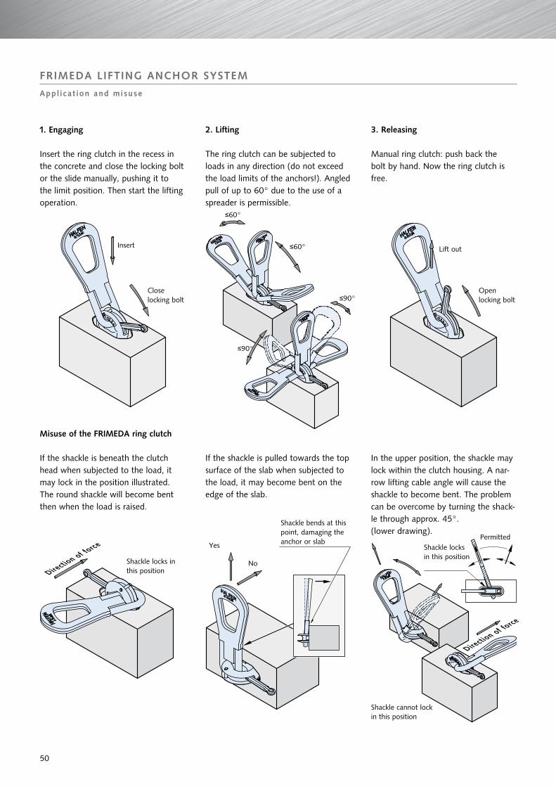
FRIMEDA LIFTINg ANCHOR SySTEM
Appl icat ion and misuse
In the upper position, the shackle may lock within the clutch housing. A nar-row lifting cable angle will cause the shackle to become bent. The problem can be overcome by turning the shack-le through approx. 45°.(lower drawing).
1. Engaging
Insert the ring clutch in the recess in the concrete and close the locking bolt or the slide manually, pushing it to the limit position. Then start the lifting operation.
Misuse of the FRIMEDA ring clutch
If the shackle is beneath the clutch head when subjected to the load, it may lock in the position illustrated. The round shackle will become bent then when the load is raised.
2. Lifting
The ring clutch can be subjected to loads in any direction (do not exceed the load limits of the anchors!). Angled pull of up to 60° due to the use of a spreader is permissible.
If the shackle is pulled towards the top surface of the slab when subjected to the load, it may become bent on the edge of the slab.
3. Releasing
Manual ring clutch: push back the bolt by hand. Now the ring clutch is free.
Insert
Close locking bolt
Lift out
Open locking bolt
≤60°
≤60°
≤90°
≤90°
Direction of fo
rce
Shackle bends at thispoint, damaging theanchor or slabYes
No
Shackle cannot lock in this position
Shackle locks in this position
Direction of fo
rce
Permitted
Shackle locks in this position
50

CONTACT HALFEN wORLDwIDE
HALFEN is represented by subs id iar ies in the fo l lowing 14 countr ies , p lease contact us :
Furthermore HALFEN is represented with sales offices and distributors worldwide. Please contact us: www.halfen.com
Austria HALFEN Gesellschaft m.b.H.Leonard-Bernstein-Str. 101220 Wien
Phone: +43 - 1 - 259 6770 E-Mail: [email protected]: www.halfen.at
Fax: +43 - 1 - 259 - 6770 99
Belgium/Luxembourg HALFEN N.V.Borkelstraat 1312900 Schoten
Phone: +32 - 3 - 658 07 20E-Mail: [email protected]: www.halfen.be
Fax: +32 - 3 - 658 15 33
China HALFEN Construction Accessories Distribution Co.Ltd.Room 601 Tower D, Vantone CentreNo.A6 Chao Yang Men Wai StreetChaoyang District Beijing · P.R. China 100020
Phone: +86 - 10 5907 3200E-Mail: [email protected]: www.halfen.cn
Fax: +86 - 10 5907 3218
Czech Republic HALFEN-DEHA s.r.o.K Vypichu 986 · Komerčni zóna Rudná, hala 625219 Rudná
Phone: +420 - 311 - 690 060E-Mail: [email protected]: www.halfen-deha.cz
Fax: +420 - 311 - 671 416
France HALFEN S.A.S.18, rue Goubet75019 Paris
Phone: +33 - 1 - 445231 00E-Mail: [email protected]: www.halfen.fr
Fax: +33 - 1 - 445231 52
germany HALFEN Vertriebsgesellschaft mbHKatzbergstraße 3 40764 Langenfeld
Phone: +49 - 2173 - 970 0E-Mail: [email protected]: www.halfen.de
Fax: +49 - 2173 - 970 225
Italy HALFEN S.r.l. Soc. UnipersonaleVia F.lli Bronzetti N° 2824124 Bergamo
Phone: +39 - 035 - 0760711E-Mail: [email protected]: www.halfen.it
Fax: +39 - 035 - 0760799
Netherlands HALFEN b.v.Oostermaat 37623 CS Borne
Phone: +31 - 742 - 6714 49E-Mail: [email protected]: www.halfen.nl
Fax: +31 - 742 6726 59
Norway HALFEN-FRIMEDA ASPostboks 20804095 Stavanger
Phone: +47 - 51 82 34 00 E-Mail: [email protected]: www.halfen.no
Fax: +47 - 51 82 34 01
Poland HALFEN Sp. z o.o.Ul. Obornicka 28760-691 Poznan
Phone: +48 - 61 - 622 14 14E-Mail: [email protected]: www.halfen.pl
Fax: +48 - 61 - 622 14 15
Spain HALFEN S.L.c/ Fuente de la Mora 2, 2° D28050 Madrid
Phone: +34 - 91 - 632 18 40E-Mail: [email protected]: www.halfen.es
Fax: +34 - 91 - 633 42 57
Sweden Halfen ABBox 150435 23 Mölnlycke
Phone: +46 - 31 - 98 58 00E-Mail: [email protected]: www.halfen.se
Fax: +46 - 31 - 98 58 01
Switzerland HALFEN Swiss AGHertistrasse 25 8304 Wallisellen
Phone: +41 - 44 - 849 78 78E-Mail: [email protected] Internet: www.halfen.ch
Fax: +41 - 44 - 849 78 79
United Kingdom /Ireland
HALFEN Ltd.Humphrys Road · Woodside EstateDunstable LU5 4TP
Phone: +44 - 1582 - 47 03 00E-Mail: [email protected]: www.halfen.co.uk
Fax: +44 - 1582 - 47 03 04
NOTES REgARDINg THIS CATALOgUETechnical and design changes reserved. The information in this publication is based on state-of-the-art technology at the time of publica-tion. We reserve the right to make technical and design changes at any time. Halfen GmbH shall not accept liability for the accuracy of the information in this publication or for any printing errors.
The Quality Management System of Halfen GmbH is certified for the locations in Germany, Austria, Poland, Switzerland and the Czech Republic according to DIN EN ISO 9001:2008, Certificate No. QS-281 HH.

T - 0
02 -
EE -
03/1
1 2.
000
03/
11
For further information please contact: www.halfen.com
© 2
011
Hal
fen
Gm
bH, G
erm
any
appl
ies
also
to
copy
ing
in e
xtra
cts.
Recommended