
FrameWIN Manual Copyright © 2014 Trailer Consultation [email protected] page 1
TRAILER CONSULTATION Tel +358 - 6 - 831 9905 Kauppatori 2 Fax +358 - 6 - 831 1008 FIN - 67100 Kokkola FINLAND www.trailerwin.com E-mail: [email protected]
FrameWIN Subframe Calculation

FrameWIN Manual Copyright © 2014 Trailer Consultation [email protected] page 2
Table of Contents
FRAMEWIN : STARTING THE COMPUTER SOFTWARE ......................................................................... 4
USING WITH TRAILERWIN COMPUTER SOFTWARE ................................................................................................ 4 START THE FRAMEWIN FROM WINDOWS ICON ..................................................................................................... 4
THE FRAMEWIN SCREEN ................................................................................................................................ 5
Loading Data .................................................................................................................................................... 6 Material Data ................................................................................................................................................... 6 Stress Data ....................................................................................................................................................... 6 Profile Data ...................................................................................................................................................... 6
TOOLBAR .............................................................................................................................................................. 7
BUTTONS ON FRAMEWIN PROGRAM USERINTERFACE .......................................................................................... 8
CHOOSING AND EDITING THE SUBFRAME PROFILES .......................................................................... 9
CHOOSING THE SUBFRAME PROFILE .................................................................................................................... 10 ADD PROFILE ...................................................................................................................................................... 10 ADD THE SIDE PLATE .......................................................................................................................................... 13 ADD THE PLATE UNDER CHASSIS FRAME ............................................................................................................ 14 EDIT THE DIMENSIONS OF THE PROFILE .............................................................................................................. 15 CHANGING AND ADDING IN SUBFRAME PROFILE .................................................................................................. 17 DELETE PROFILE ................................................................................................................................................. 19 CHASSIS FRAME ................................................................................................................................................... 20 INTERPRETING FRAMEWIN PRINTOUT ................................................................................................................ 22
Chassis frame reinforcement .......................................................................................................................... 25 Frame width in FrameWIN ............................................................................................................................ 28
MATERIAL OF THE BEAMS ........................................................................................................................... 29
LOAD / FRAME BENDING MOMENT ......................................................................................................... 30
THE MOMENT CAUSED BY THE CRANE ................................................................................................................ 30 THE MOMENT CAUSED BY THE TAIL GATE LIFTER .............................................................................................. 31
DYNAMIC LOADING FACTOR AND CALCULATION SYSTEM ............................................................ 32
CHOOSING CALCULATION SYSTEM ...................................................................................................................... 32 CALCULATION BY ”BASIC FRAMEWIN SYSTEM” ................................................................................................ 32 CALCULATION BY EN12999 SYSTEM .................................................................................................................. 33
FILE FUNCTIONS .............................................................................................................................................. 34
OPEN ................................................................................................................................................................... 35 SAVE AS .............................................................................................................................................................. 36 SAVE AS DXF-FILE AND SAVE AS DXF-FILE (ENTITIES ONLY) ......................................................................... 36
PRINTOUT ........................................................................................................................................................... 36
DRAW TEXT ONTO THE PICTURE .............................................................................................................. 37
DRAW LINES, RECTANGLES, DIMENSIONS, ETC ................................................................................... 37
DRAW DIMENSIONS: HORIZONTAL AND VERTICAL. ............................................................................................. 38
LIST OF SYMBOLS ............................................................................................................................................ 39
LICENCE AGREEMENT ................................................................................................................................... 39
WARRANTY ........................................................................................................................................................ 39

FrameWIN Manual Copyright © 2014 Trailer Consultation [email protected] page 3
SUBFRAME CALCULATION THEORY IN FRAMEWIN ........................................................................... 40
STRESS CALCULATION : BENDING MOMENT ON U-BEAM : .......................................................... 40 COMBINED BEAM : CHASSIS FRAME + SUBFRAME .......................................................................... 41
Flexible mounting : subframe mounted with brackets or clamps .............................................................. 41 Rigid mounting : subframe mounted with shear resisting plates ............................................................. 43
CALCULATION WITH NEW STANDARD EN12999.................................................................................... 45
NEW CALCULATION SYSTEM EN12999 IN FRAMEWIN ....................................................................................... 45 About calculation system EN12999/EN13001 ................................................................................................ 45 HD5 for cranes with automatic speed control Formulas and symbols ......................................................... 45 Formulas and symbols .................................................................................................................................... 46
FrameWIN Manual Copyright © 2014 Trailer Consultation [email protected] page 4
FrameWIN : Starting the computer software
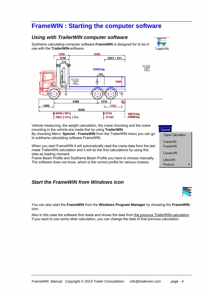
Using with TrailerWIN computer software Subframe calculating computer software FrameWIN is designed for to be in use with the TrailerWIN-software.
Vehicle measuring, the weight calculation, the crane choosing and the crane mounting in the vehicle are made first by using TrailerWIN. By choosing Menu: Special - FrameWIN from the TrailerWIN menu you can go to subframe calculating software FrameWIN. When you start FrameWIN it will automatically read the crane data from the last made TrailerWIN calculation and it will do the first calculations by using this data as loading moment. Frame Beam Profile and Subframe Beam Profile you have to choose manually. The software does not know, which is the correct profile for various chassis.
Start the FrameWIN from Windows icon
You can also start the FrameWIN from the Windows Program Manager by choosing the FrameWIN-icon.
Also in this case the software first reads and shows the data from the previous TrailerWIN-calculation. If you want to use some other calculation, you can change the data of that previous calculation.

FrameWIN Manual Copyright © 2014 Trailer Consultation [email protected] page 5
The FrameWIN Screen On the screen you will find the Basic Data, Data of Loading (Moment), Data of Material, Calculating results: Stress and Safety Factor, Details of Profiles (Dimensions and Cross Area Values) and Calculated Cross Area Values for Combined Beam (Chassis Frame + Subframe Profiles). Picture when using Basic FrameWIN System calculation method. For more information about calculation systems see Dynamic Loading Factor and Calculation system on page 32.

FrameWIN Manual Copyright © 2014 Trailer Consultation [email protected] page 6
Loading Data Loading Data is taken from the last TrailerWIN Calculation (Calculation with Crane) or you have edited the data.
You can edit loading data selecting Menu: Edit - Moment, or selecting Toolbar Button: Moment.
Material Data
Re = Yield strength in N/mm2 You can edit Material data selecting Menu: Edit - Material. You can choose different steel qualities for Subframe and for Chassis frame. Notice that both Subframe Profiles and Chassis Frame Profiles must be same material. For example if Subframe Profile is steel should Chassis Frame Profile be steel as well (or if Subframe Profile is aluminium should Chassis Frame Profile be aluminium also etc). The Program cannot calculate combination with Materials with different E-values (E=modulus of elasticity).
Stress Data
FrameWIN calculates stress using two different methods: Combined beam data with Flexible mounting [A] and Combined beam data with mounting with shear resisting plates [B]. The Method of calculating is explained in the Appendix SUBFRAME CALCULATION.
Profile Data The table shows Cross Area Data of all the chosen profiles:
These Cross section dimensions are given for one beam:
Height H (mm) Cross section area A (mm2 ) Second moment of area Ix ( cm4 ) Section modulus Wx ( cm3 ) Beam weight / meter G ( kg/m )

FrameWIN Manual Copyright © 2014 Trailer Consultation [email protected] page 7
Two last rows show the Ix and Wx for combined beam, [A] Flexible mounting and [B] Shear resisting mounting.
Toolbar
Toolbar buttons:
Open, Save or Print Calculation
The Data of Loading Moments: Crane Load and Outreach
Choosing the Subframe Profiles
Set values for Dynamic Coefficient and Safety Factor warning limit and choose calculation method
Draw objects: line, rectangle, etc.
Draw Text
Exit FrameWIN

FrameWIN Manual Copyright © 2014 Trailer Consultation [email protected] page 8
Buttons on FrameWIN program userinterface
Save a FrameWIN calculation and subframe profile
Open a saved FrameWIN calculation and subframe profile
Print current FrameWIN project
Add profile or sideplate on subframe
Edit crane information weights and measures
Edit dynamic coefficient or safety factors for subframe and chassis
Draw more details on FrameWIN picture or add more measures
Add own text and comment on FrameWIN picture
Quit using FrameWIN

FrameWIN Manual Copyright © 2014 Trailer Consultation [email protected] page 9
Choosing and Editing the Subframe Profiles Click the Subframe-button or select the menu EDIT - SUBFRAME or CHASSIS FRAME.

FrameWIN Manual Copyright © 2014 Trailer Consultation [email protected] page 10
Choosing the Subframe Profile You can change the profile shape by choosing shape from the Profile Shape List. Choosing the shape changes profile list in Profile Size List. When the shape is correct, you can choose Profile Size from the Profile Size List.
Add Profile For adding a profile, click the Add Profile button or use Menu:Edit - Add Profile. You will get a new profile number (2) on the List of Profiles on the top of the screen. Choose profile Shape from the Profile Shape List. Take for example a Rectangular Hollow Section (horizontal)

FrameWIN Manual Copyright © 2014 Trailer Consultation [email protected] page 11
As next step you have to choose the Profile Size from the Profile Size List.
FrameWIN Manual Copyright © 2014 Trailer Consultation [email protected] page 12
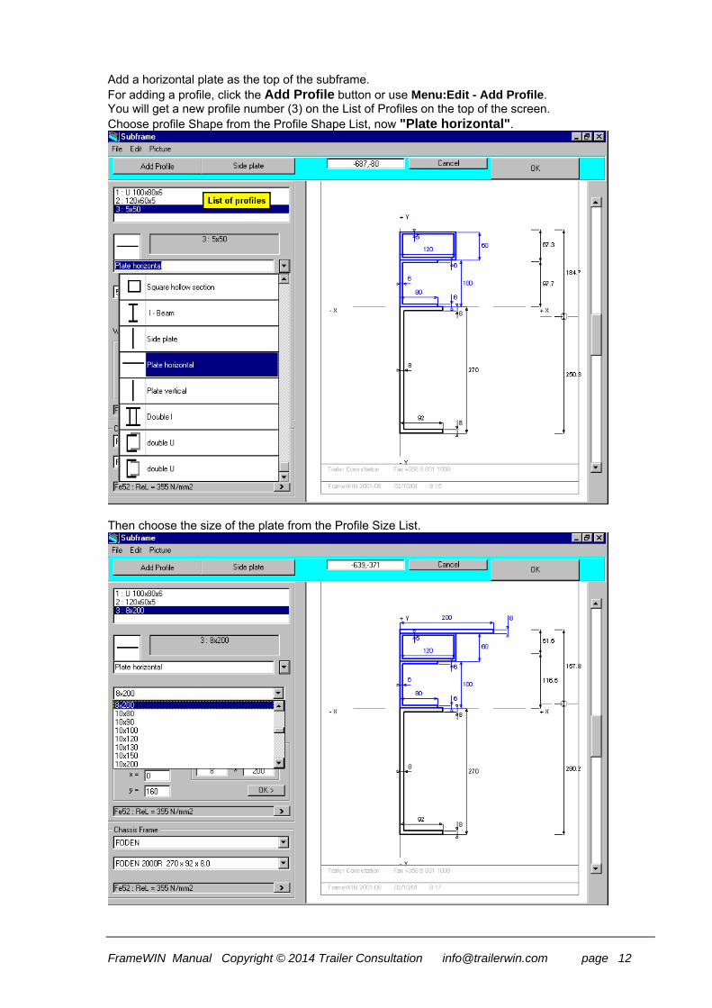
Add a horizontal plate as the top of the subframe. For adding a profile, click the Add Profile button or use Menu:Edit - Add Profile. You will get a new profile number (3) on the List of Profiles on the top of the screen. Choose profile Shape from the Profile Shape List, now "Plate horizontal".
Then choose the size of the plate from the Profile Size List.

FrameWIN Manual Copyright © 2014 Trailer Consultation [email protected] page 13
Add the Side Plate
For adding a profile, click Side Plate Button or use Menu:Edit - Add Side Plate. You will get a new profile number (4) on the Profile list on the top of the screen. The Profile Shape List shows "Side Plate". Choose the size of the Side Plate from the Profile Size List. If you do not find suitable plate size from the list you can type the dimensions to "Height" and "Width" textboxes (Look at the picture). You can locate the side plate by typing the x- and y-coordinates in "Coordinates for the plate" textboxes. The coordinates mean the lower left corner of the cross area of the plate or profile. After typing the coordinates x and y click small OK button (Refresh picture) to get the picture redrawn.
FrameWIN Manual Copyright © 2014 Trailer Consultation [email protected] page 14
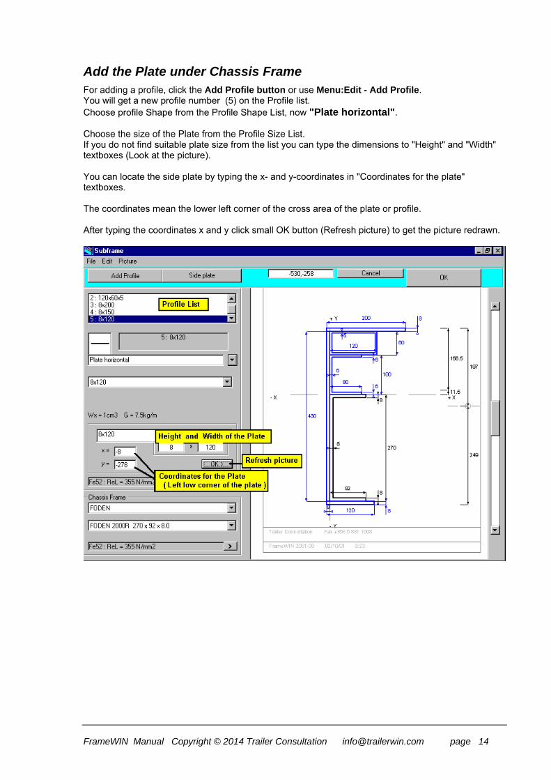
Add the Plate under Chassis Frame For adding a profile, click the Add Profile button or use Menu:Edit - Add Profile. You will get a new profile number (5) on the Profile list. Choose profile Shape from the Profile Shape List, now "Plate horizontal". Choose the size of the Plate from the Profile Size List. If you do not find suitable plate size from the list you can type the dimensions to "Height" and "Width" textboxes (Look at the picture). You can locate the side plate by typing the x- and y-coordinates in "Coordinates for the plate" textboxes. The coordinates mean the lower left corner of the cross area of the plate or profile. After typing the coordinates x and y click small OK button (Refresh picture) to get the picture redrawn.
FrameWIN Manual Copyright © 2014 Trailer Consultation [email protected] page 15
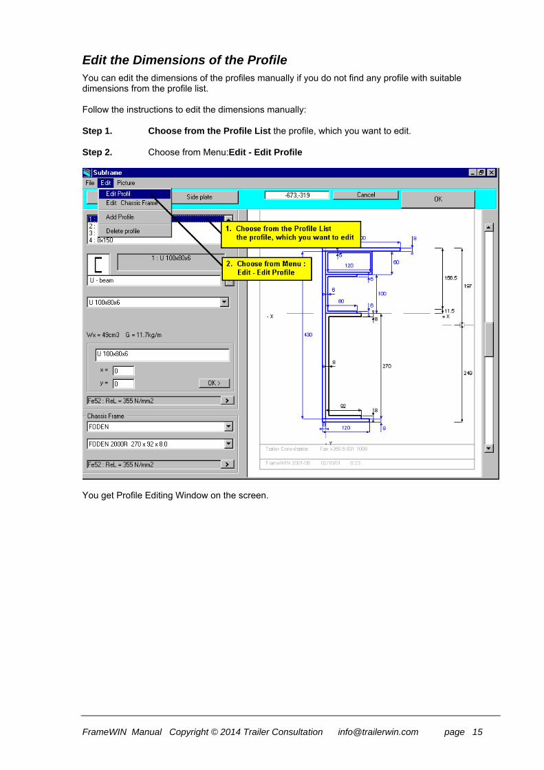
Edit the Dimensions of the Profile You can edit the dimensions of the profiles manually if you do not find any profile with suitable dimensions from the profile list. Follow the instructions to edit the dimensions manually: Step 1. Choose from the Profile List the profile, which you want to edit. Step 2. Choose from Menu:Edit - Edit Profile
You get Profile Editing Window on the screen.

FrameWIN Manual Copyright © 2014 Trailer Consultation [email protected] page 16
You get a picture of a profile cross-area shape. You can edit dimension of the cross area by typing new dimensions on the textboxes. After the dimensions have been given, click the small OK-button on the picture, and the program redraws the cross area with new dimension values.
Furthermore on the right side on the picture are the dimension s1 and s2 (mm), that show the Centroid of the cross area. To give a name for the edited profile, type the new name, or use Name Automatic. Click the Check Box Name Automatic for turning automatic on or off.

FrameWIN Manual Copyright © 2014 Trailer Consultation [email protected] page 17
Changing and adding in subframe profile
From subframe menu You can add more profiles on subframe or add a sideplate on subframe. You can choose shape of profile, measures for height, width & length and material and give exact coordinates for each added new profile All added profiles will be taken into consideration in FrameWIN stress and safety factor calculation. Calculation are made for fixed mounting and for flexible mounting. Safety factors are calculated for dynamic coefficients and for static coefficients.

FrameWIN Manual Copyright © 2014 Trailer Consultation [email protected] page 18
You can choose shape of profile for each added new profile. List of profile types include: 1. U - beam 2. Rectangular hollow section (vertical) 3. Rectangular hollow section (Horizontal) 4. Square hollow section 5. I - beam 6. Side plate 7. Plate Horizontal 8. Plate vertical 9. Double I 10. Double U (version 1) 11. Double U (version2) List of materials in FrameWIN include: Fe52 (default material), Fe510, St52, Gr50, S690, S420, Fe E 420, Fe E490, Fe 44, Fe430, St44, Gr43, Fe37, Fe360, St37, Gr40 You can also give own material and yield strength for the material, but it will not saved into program. Next time You want to use same material, You will need to give yield strength values again. All materials in chassis frame, subframe and added subframe profiles must be steel. All must have same elastic modulus value. FrameWIN can not calculate correctly if elastic modulus is different for different parts. (for example steel and aluminium).
FrameWIN Manual Copyright © 2014 Trailer Consultation [email protected] page 19
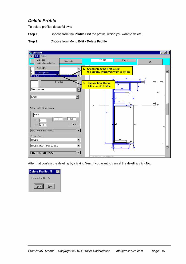
Delete Profile To delete profiles do as follows: Step 1. Choose from the Profile List the profile, which you want to delete. Step 2. Choose from Menu:Edit - Delete Profile
After that confirm the deleting by clicking Yes. If you want to cancel the deleting click No.

FrameWIN Manual Copyright © 2014 Trailer Consultation [email protected] page 20
Chassis frame
On the left - lower corner on the Subframe Window you find Lists for Chassis Frame: You can choose Chassis Fabricate and then the Profile Size. Notice that choosing of the Profile Size comes not automatically from TrailerWIN. Chassis database in TrailerWIN does not include data of frame profiles. You have to choose manually the correct profile size. From the upper list box you can choose the truck make. The program knows the frame profiles of the trucks on the list. If you do not find the wanted truck make from the list, or wanted profile size from the lower list, you can edit the beam dimensions manually. For this editing dimensions for Chassis Frame; use Menu: Edit - Edit:Chassis Frame (menu in Subframe Window)
Even though you have entered the Subframe calculation in TrailerWIN, where you have already chosen a specific Truck model, the TrailerWIN does not know which beam profile shape belongs to this truck model. You have to choose the Beam Profile model separately. TrailerWIN Truck Data files do not contain frame beam dimension data.

FrameWIN Manual Copyright © 2014 Trailer Consultation [email protected] page 21
Load / Frame Bending Moment In the Calculation the Crane or the Tail gate lifter causes the Bending Moment. The Bending Moment is calculated by using the load and the outreach and also by using the cranes own weight and the center of the gravity. The Moment caused by the Crane
FrameWIN Manual Copyright © 2014 Trailer Consultation [email protected] page 22
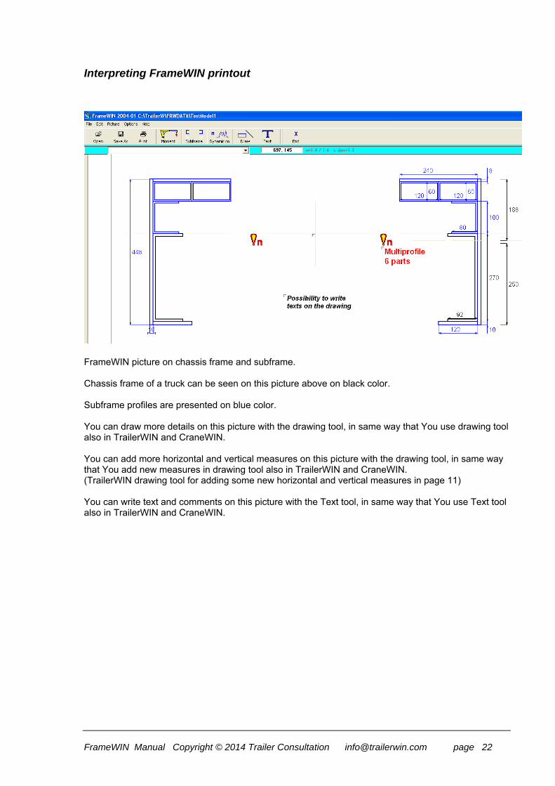
Interpreting FrameWIN printout
FrameWIN picture on chassis frame and subframe. Chassis frame of a truck can be seen on this picture above on black color. Subframe profiles are presented on blue color. You can draw more details on this picture with the drawing tool, in same way that You use drawing tool also in TrailerWIN and CraneWIN. You can add more horizontal and vertical measures on this picture with the drawing tool, in same way that You add new measures in drawing tool also in TrailerWIN and CraneWIN. (TrailerWIN drawing tool for adding some new horizontal and vertical measures in page 11) You can write text and comments on this picture with the Text tool, in same way that You use Text tool also in TrailerWIN and CraneWIN.

FrameWIN Manual Copyright © 2014 Trailer Consultation [email protected] page 23
FrameWIN table on safety factors, stresses, materials and list of profiles
FrameWIN table on safety factors, stresses for both flexible mounting and fixed mounting. Static & dynamic safety factors should all be more than values 1.25 or 1.4. In this example stress on lower flange is critical, but upper flange chassis frame are ok.

FrameWIN Manual Copyright © 2014 Trailer Consultation [email protected] page 24
The table shows Cross Area Data of all the chosen profiles:
These Cross section dimensions are given for one beam: Height H (mm) Cross section area A (mm2 ) Second moment of area Ix ( cm4 ) Section modulus Wx ( cm3 ) Beam weight / meter G ( kg/m ) Two last rows on the table show the Ix and Wx value s for the combined beam: All subframe profiles + chassis frame together in two different mounting systems: [A] Flexible mounting [B] Shear resisting mounting (Fixed mounting). FrameWIN is a helping tool program to choose the profile for subframe and to calculate cross-section values on one point. These one cross-section values are calculated for A) Flexible mounting B) Fixed mounting (shear resisting). FrameWIN does not calculate the whole subframe in longitudinal direction and does not calculate the distribution of the chassis bending moment on different places. FrameWIN user must self make the choice if subframe mounting is flexible or fixed. For more detailed subframe and frame calculation is needed to use a FEM strength calculation program (Finite Elements Method).
FrameWIN Manual Copyright © 2014 Trailer Consultation [email protected] page 25
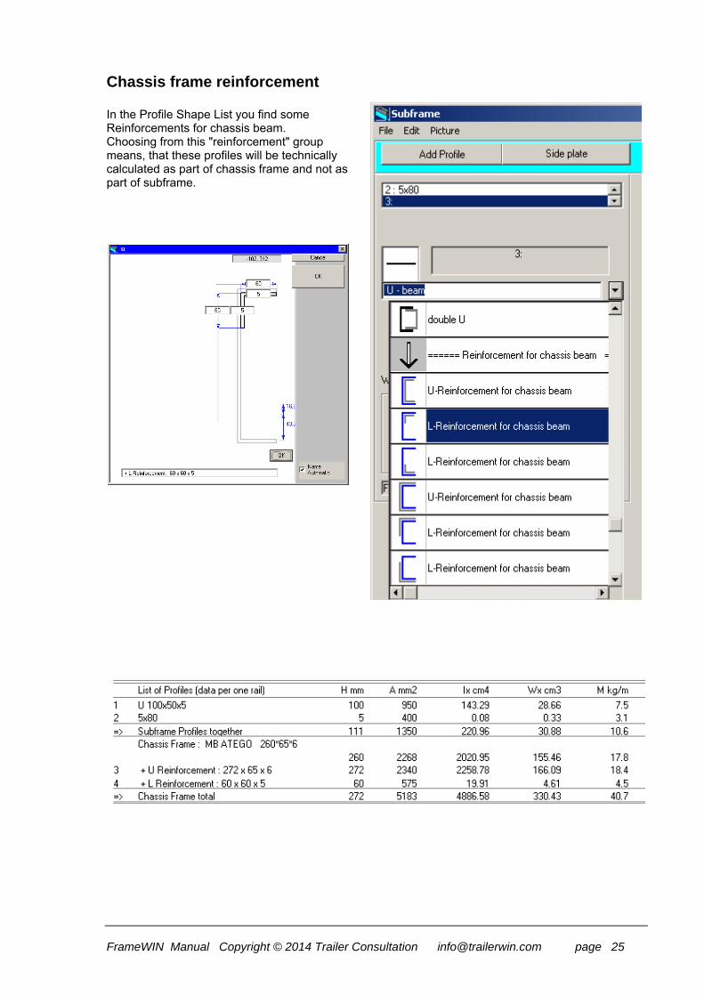
Chassis frame reinforcement In the Profile Shape List you find some Reinforcements for chassis beam. Choosing from this "reinforcement" group means, that these profiles will be technically calculated as part of chassis frame and not as part of subframe.

FrameWIN Manual Copyright © 2014 Trailer Consultation [email protected] page 26
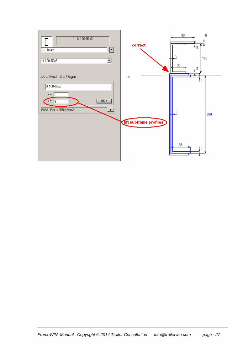
Warning in FrameWIN: If you in FrameWIN choose a reinforcement, which is outside of chassis beam, you have to check manually, that subframe parts will be on a correct height above the chassis beam. FrameWIN can not automatically check, if the profiles are "inside each other". You need to lift subframe profiles using the dimension of reinforcement upper flange thickness.
FrameWIN Manual Copyright © 2014 Trailer Consultation [email protected] page 27

FrameWIN Manual Copyright © 2014 Trailer Consultation [email protected] page 28
Frame width in FrameWIN

FrameWIN Manual Copyright © 2014 Trailer Consultation [email protected] page 29
Material of the Beams Menu: Edit - MATERIAL
By choosing the materials from list boxes, you automatically get the material name and the Yield strength minimum for the chosen material on specific textboxes. You can edit both of these separately, but in this case for example changing the material name from the textbox does not change Yield strength minimum. You have to change that manually too.

FrameWIN Manual Copyright © 2014 Trailer Consultation [email protected] page 30
Load / Frame Bending Moment In the Calculation the Crane or the Taillift causes the Bending Moment. The Bending Moment is calculated by using the load and the outreach and also by using the crane own weight and the center of the gravity.
The Moment caused by the Crane

FrameWIN Manual Copyright © 2014 Trailer Consultation [email protected] page 31
The Moment caused by the Tail Gate Lifter By choosing the option button: Tail Gate Lifter you can give the Moment caused by the Tail Gate Lifter.
The data on Tail Gate Lifter and Load on the Lifter are given by typing on textboxes on the screen:

FrameWIN Manual Copyright © 2014 Trailer Consultation [email protected] page 32
Dynamic Loading Factor and Calculation system
Choosing calculation system At first program start You will be asked to choose which calculation system the program will use as default. It is possible to modify this setting later using menu Options->Options->Default Values->Default Calculation System. This setting will then be the default setting every time You begin a new calculation.. By choosing Options->Calculation System from menu or by clicking Dynamic coefficient-button You will get the opportunity to set calculation method and also setting options for the calculation.
Calculation by ”Basic FrameWIN system” Dynamic coefficient c dyn
Default value for Dynamic Coefficient in FrameWIN is c dyn = 1.3. You can anyway change the default value from Menu: Options - Default Values Dynamic Coefficient can be calculated using the formula
c dyn = 1.1 x 0.0022 x 60 x v (m/s) c dyn no more than 1.3 v = crane lift velocity
If You type a new value in the textbox for crane lift velocity (m/s) , the program calculates the corresponding Dynamic Coefficient. On the other hand you can also type the wanted Dynamic Coefficient into the textbox. Dynamic Coefficient increases the Moment used in the calculation:
M dyn = c dyn x M static Safety factor n means here the warning limit for the safety factor. The Program calculates the safety factor for the specific case. If this is lower than the the warning
limit, which You choose here, the program shows a warning !n. You can anyway change the default value for Safety Factor from Menu: Options - Default Values

FrameWIN Manual Copyright © 2014 Trailer Consultation [email protected] page 33
Calculation by EN12999 system When You choose calculation by EN12999, EN13001 You will get the following options to set:
Vertical hook speed – highest possible hook-speed rising or lowering.
Load combination
o A1-normal lifting/lowering from one function
o C1-exceptional load, total speed from all functions activated
o HC1-HD1..5 Hoist Drive Class. Select correct HD-class depending on the valve-system on the crane.
o HD1- On/Off-valve type.
o HD4- Normal spool valve, speed can be manipulated directly by user
o HD5- Automatic speed control of crane movements.
Safety factor for Chasis Frame and Subframe. Normally 1.1, that is also recommended by the standard. Safety Factor can be set by user.
In this window You can see the formulas for calculating Ф2-factor. These formulas will change depending on which Load Combination (A1, C1) You have chosen. These settings and formulas will also be printed out.
FrameWIN Manual Copyright © 2014 Trailer Consultation [email protected] page 35
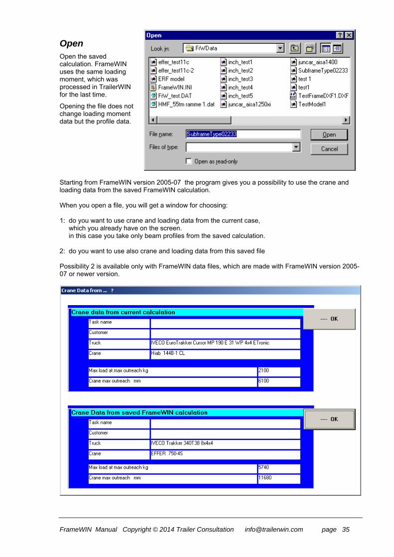
Open Open the saved calculation. FrameWIN uses the same loading moment, which was processed in TrailerWIN for the last time.
Opening the file does not change loading moment data but the profile data. Starting from FrameWIN version 2005-07 the program gives you a possibility to use the crane and loading data from the saved FrameWIN calculation. When you open a file, you will get a window for choosing: 1: do you want to use crane and loading data from the current case, which you already have on the screen. in this case you take only beam profiles from the saved calculation. 2: do you want to use also crane and loading data from this saved file Possibility 2 is available only with FrameWIN data files, which are made with FrameWIN version 2005-07 or newer version.

FrameWIN Manual Copyright © 2014 Trailer Consultation [email protected] page 36
Save As Save the profile combination. The loading data will not to be saved.
Save As DXF-File and Save As DXF-File (Entities only) Save the Picture of the Frame (Combined Profile) in DXF format. Choosing "Entities only" means, that the file includes only the drawing objects. DXF file can be used in CAD software and also some other computer software can read DXF-files. In DXF format you will get the drawing as vector drawing in CAD software.
Printout
The printout on paper.
Using small blank buttons, you can print only one page, frame with calculation results or only profile combination in bigger scale. The big OK button prints both pages if both checkboxes are marked, or only one of the pages, depending on which one is marked. For printing you must give your name in field: "Calculation made by". With checkbox Colors you can choose printing in colours.

FrameWIN Manual Copyright © 2014 Trailer Consultation [email protected] page 37
Draw Text onto the picture
You can write own texts onto the picture. Following picture shows the possibilities. The size of the text depends on the size of the picture.
On the Text List you see all the text you have in this calculation. With mouse-click on the text line you can choose the text for editing. Press Enter to change the line.
Draw Lines, Rectangles, Dimensions, etc
You can draw simple drawings on the picture.

FrameWIN Manual Copyright © 2014 Trailer Consultation [email protected] page 38
Choose the type of the object by using Shape Buttons “LINE”, “RECTANGLE”, “CIRCLE”. Then draw the line or rectangle or circle with mouse onto the picture. You can drag point with dragging the grips (yellow rectangles). When you click OK, the grips disappear. Click the Edit-Button to get the grips back.
Draw Dimensions: horizontal and vertical. When you draw a dimension with mouse, you will get the correct dimension text automatically. You can anyway change the dimension text; you only write a new text on the dimension editing box, and click the small ok button on the right side of the editing box. If you later edit this dimension with the mouse, you get again automatically new dimension text. You can choose arrow position with direction, when you are drawing a dimension with dragging mouse. The example shows the result and the mouse movement direction, from point 1 to point 2.
FrameWIN Manual Copyright © 2014 Trailer Consultation [email protected] page 39
List of Symbols
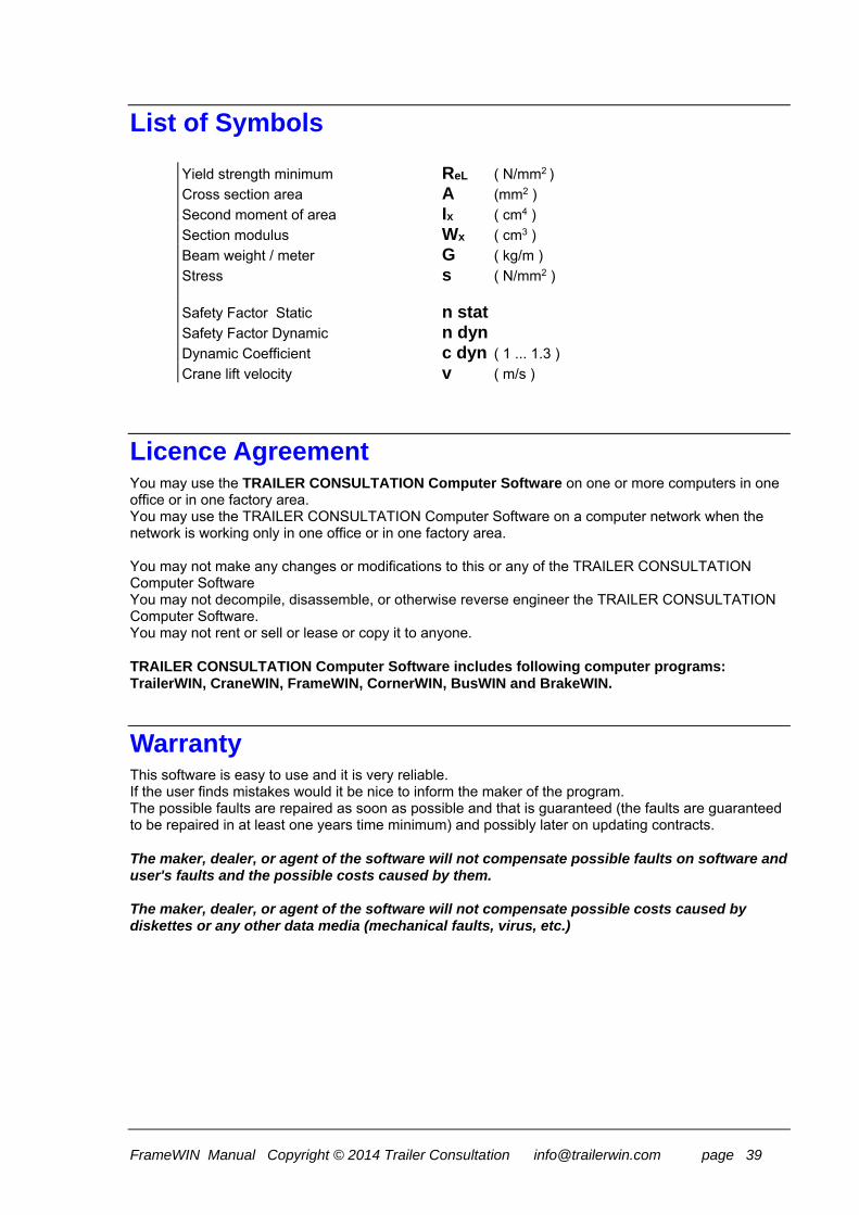
Yield strength minimum ReL ( N/mm2 )
Cross section area A (mm2 )
Second moment of area Ix ( cm4 )
Section modulus Wx ( cm3 )
Beam weight / meter G ( kg/m )
Stress s ( N/mm2 ) Safety Factor Static n stat Safety Factor Dynamic n dyn
Dynamic Coefficient c dyn ( 1 ... 1.3 )
Crane lift velocity v ( m/s )
Licence Agreement You may use the TRAILER CONSULTATION Computer Software on one or more computers in one office or in one factory area. You may use the TRAILER CONSULTATION Computer Software on a computer network when the network is working only in one office or in one factory area. You may not make any changes or modifications to this or any of the TRAILER CONSULTATION Computer Software You may not decompile, disassemble, or otherwise reverse engineer the TRAILER CONSULTATION Computer Software. You may not rent or sell or lease or copy it to anyone. TRAILER CONSULTATION Computer Software includes following computer programs: TrailerWIN, CraneWIN, FrameWIN, CornerWIN, BusWIN and BrakeWIN.
Warranty This software is easy to use and it is very reliable. If the user finds mistakes would it be nice to inform the maker of the program. The possible faults are repaired as soon as possible and that is guaranteed (the faults are guaranteed to be repaired in at least one years time minimum) and possibly later on updating contracts. The maker, dealer, or agent of the software will not compensate possible faults on software and user's faults and the possible costs caused by them.
The maker, dealer, or agent of the software will not compensate possible costs caused by diskettes or any other data media (mechanical faults, virus, etc.)

FrameWIN Manual Copyright © 2014 Trailer Consultation [email protected] page 40
SUBFRAME CALCULATION THEORY IN FRAMEWIN
STRESS CALCULATION : BENDING MOMENT ON U-BEAM :
Bending moment M at a certain cross-section makes the normal stress on a longitudinal fiber at a distance y from the neutral axis of the beam:
M y
I
M
W
The second moment Ix (moment of inertia) and section modulus
Wx of a symmetrical U-cross-section area can be calculated as follows:
IB H b h
WI
H
I
H
x
x
x x
3 3
12 12
2
2
FrameWIN Manual Copyright © 2014 Trailer Consultation [email protected] page 41
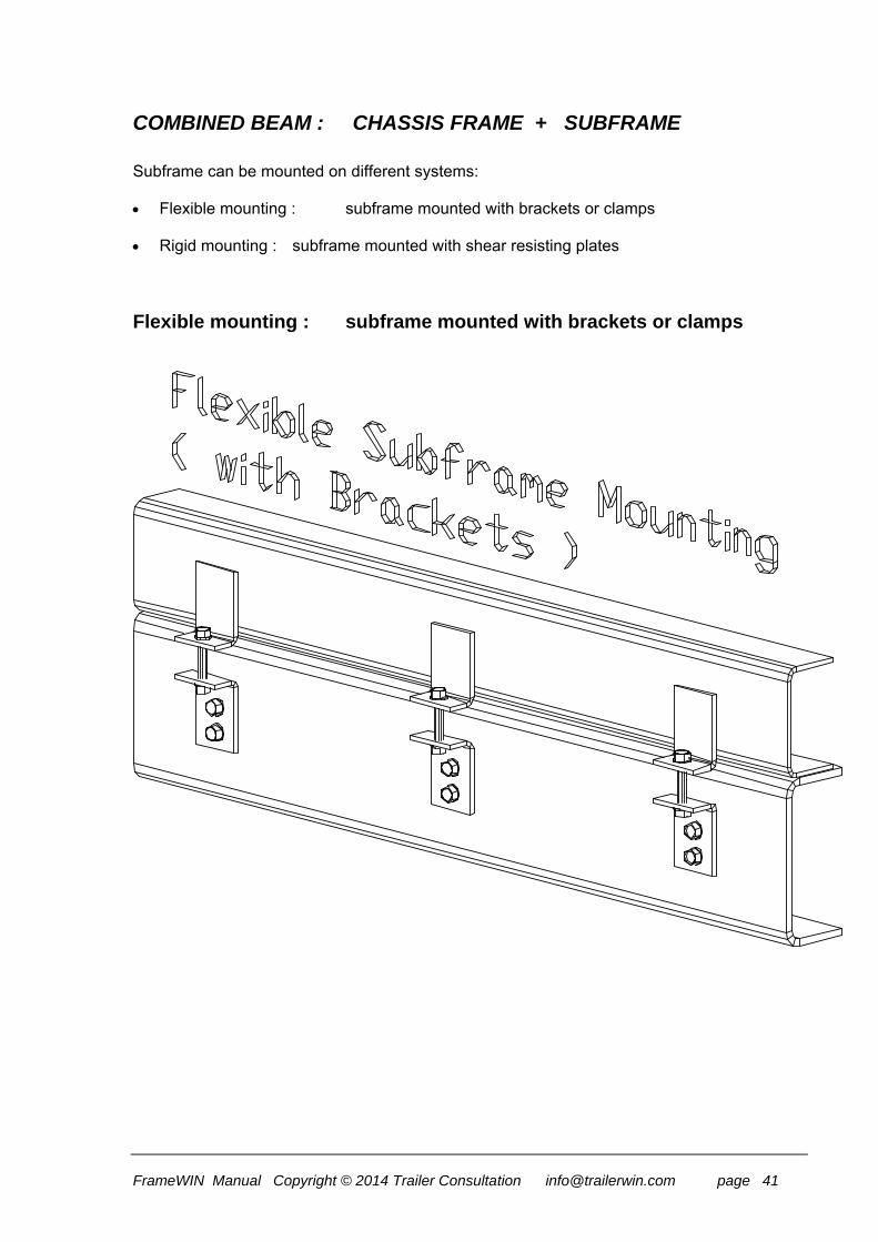
COMBINED BEAM : CHASSIS FRAME + SUBFRAME Subframe can be mounted on different systems: Flexible mounting : subframe mounted with brackets or clamps Rigid mounting : subframe mounted with shear resisting plates
Flexible mounting : subframe mounted with brackets or clamps

FrameWIN Manual Copyright © 2014 Trailer Consultation [email protected] page 42
With a flexible mounting Ix and Wx can be calculated for a combined beam as follows:
I I I
WI I
ee e e e e
C F S
C
F S
C
C F F S S
max , , ,1 2 1 2
Maximum normal stresses with bending moment M at a combined beam cross-section with flexible mounting are :
F1
F1
C
F 2
F 2
C
S1
S1
C
S2
S2
C
M e
Ion chassis frame lower fibers
M e
Ion chassis frame upper fibers
M e
Ion subframe lower fibers
M e
Ion subframe upper fibers

FrameWIN Manual Copyright © 2014 Trailer Consultation [email protected] page 43
Rigid mounting : subframe mounted with shear resisting plates
With a rigid mounting the calculation of Ix and Wx for a combined beam turns out to be more complicated : At first we have to calculate the centroid (Center of gravity) yC for the combined cross-
section. With dimension yC we calculate zF and zS and then the second moment of combined
cross-section IC and the section modulus for the combined cross-section WC.

FrameWIN Manual Copyright © 2014 Trailer Consultation [email protected] page 44
yA y A H y
A A
z y y
z H y y
I I A z I A z
WI
ee y y
CF F S F S
F S
F C F
S F S C
C F F F S S S
CC
CC C c
( )
( ) ( )
max( , )
2 2
1 2
Maximum normal stresses with bending moment M at a combined beam cross-section with rigid mounting are :
FC1
C
SC2
C
M y
Ion frame lower fibers
M y
Ion subframe upper fibers
In both cases : The normal stress distribution in figures: Young's modulus E for chassis frame material = Young's modulus E for subframe material.
With all steel qualities E 210 000 N/mm2 Safety factor can be calculated:
nR
R Yield point for material Fe R N mm
calculated stress
ee e
; , /52 350 2
Bending Moment M In FrameWIN software by Trailer Consultation the bending moment M is the lifting moment of the crane multiplied by dynamic coefficient ( default = 1.3 ).

FrameWIN Manual Copyright © 2014 Trailer Consultation [email protected] page 45
CALCULATION WITH NEW STANDARD EN12999
Subframe safety factor can now be made by two different systems, Basic FrameWIN System or EN12999/EN13001. The main difference from the Basic FrameWIN System is that it uses different safety-factors for crane-weight and the load. The new standard also takes notice of differencies in operation methods. On a crane with automatic speed control the forces on sudden rising/stopping will be much lower than on cranes with On/Off-type valve. FrameWIN now gives you the possibility to choose calculation method.
New calculation system EN12999 in FrameWIN
In FrameWIN You can choose calculation system for dynamic forces. By choosing Options->Calculation system or by clicking on Dynamic coefficient-button on menu. When choosin EN12999, EN13001 You will have to choose following settings:
Vertikal hook Speed
Load Combination A1/C1 HD class of Hoist Drive.
HD1/HD4/HD5. Safety factors for Frame
and Subframe. Recommendation by standard is: γm = 1.1
The calculation is made for mobile cranes, Hoist Class 1 (HC1). You will also get the settings and formulas on the outprint.
About calculation system EN12999/EN13001 Here is a short description of the new standard EN12999. For more information, please refer to the standards EN12999, EN13001.
FrameWIN makes calculation by Hoist Class 1 (HC1) which is the Hoist Class for mobile- and flexibile mounted cranes. (HC2 is for rigidly mounted cranes)
From options window You can make following selections for Hoist Drive Class:
HD1 for cranes with On/Off –type valves regulating lifting and lowering
HD4 for cranes with normal spool valve operated by user.
HD5 for cranes with automatic speed control
FrameWIN Manual Copyright © 2014 Trailer Consultation [email protected] page 46
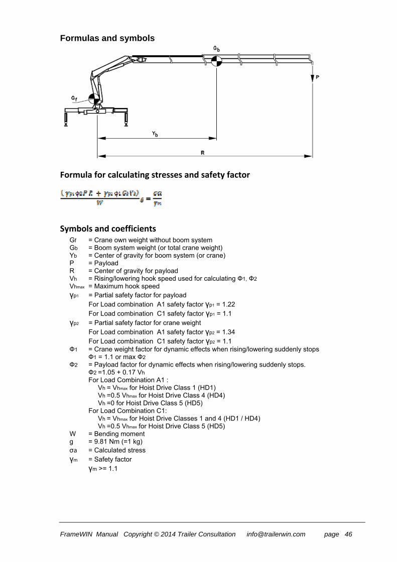
Formulas and symbols
Formula for calculating stresses and safety factor
Symbols and coefficients Gf = Crane own weight without boom system Gb = Boom system weight (or total crane weight) Yb = Center of gravity for boom system (or crane) P = Payload R = Center of gravity for payload Vh = Rising/lowering hook speed used for calculating Ф1, Ф2 Vhmax = Maximum hook speed γp1 = Partial safety factor for payload
For Load combination A1 safety factor γp1 = 1.22 For Load combination C1 safety factor γp1 = 1.1
γp2 = Partial safety factor for crane weight For Load combination A1 safety factor γp2 = 1.34 For Load combination C1 safety factor γp2 = 1.1
Ф1 = Crane weight factor for dynamic effects when rising/lowering suddenly stops Ф1 = 1.1 or max Ф2
Ф2 = Payload factor for dynamic effects when rising/lowering suddenly stops. Ф2 =1.05 + 0.17 Vh
For Load Combination A1 : Vh = Vhmax for Hoist Drive Class 1 (HD1) Vh =0.5 Vhmax for Hoist Drive Class 4 (HD4) Vh =0 for Hoist Drive Class 5 (HD5)
For Load Combination C1: Vh = Vhmax for Hoist Drive Classes 1 and 4 (HD1 / HD4) Vh =0.5 Vhmax for Hoist Drive Class 5 (HD5)
W = Bending moment g = 9.81 Nm (=1 kg) σa = Calculated stress γm = Safety factor
γm >= 1.1
Recommended


