Embed Size (px)
Citation preview

Investigation of the February 5, 2016 Crane
Collapse at 40 Worth Street, New York, NY
U.S. Department of Labor
Occupational Safety and Health Administration Directorate of Construction
July 2016

Investigation of the February 5, 2016 Crane Collapse at 40 Worth Street, New York, NY
_____________________________________________________________________________________
2
Report
Investigation of the
February 5, 2016 Crane
Collapse at 40 Worth
Street, New York, NY
July 2016
Report Prepared by
Mohammad Ayub, P.E., S.E.
Office of Engineering Services
Directorate of Construction
Contributions to this report by
Alan Lu, Ph.D., P.E.
Gopal Menon, P.E.
Directorate of Construction

Investigation of the February 5, 2016 Crane Collapse at 40 Worth Street, New York, NY
_____________________________________________________________________________________
3
TABLE OF CONTENTS PAGE NO.
1. Introduction ...................................................................................................................................... 5
2. The Incident ..................................................................................................................................... 5
3. Data from the Crane’s Computer (CPU data) ................................................................................ 14
4. Engineering Analysis ..................................................................................................................... 18
5. Conclusions .................................................................................................................................... 38
APPENDIX ............................................................................................................................................ 39

Investigation of the February 5, 2016 Crane Collapse at 40 Worth Street, New York, NY
_____________________________________________________________________________________
4
LIST OF FIGURES
Figure 1 Project location plan (taken from Google Maps). .......................................................................... 6
Figure 2 Jib head section after the incident – aerial view. ........................................................................... 7
Figure 3 Jib head section after the incident – street view 1. ........................................................................ 8
Figure 4 Jib head section after the incident – street view 2. ........................................................................ 8
Figure 5 Boom and jib on the ground after the incident – aerial view. ........................................................ 9
Figure 6 Boom and jib on the ground after the incident – street view. ........................................................ 9
Figure 7 Crane and counterweights after the incident. ............................................................................... 10
Figure 8 Boom dimensions. ....................................................................................................................... 11
Figure 9 Luffing jib dimensions. ................................................................................................................ 12
Figure 10 Liebherr input for the calculation of ground pressure of LR 1300. ........................................... 13
Figure 11 Sample page from CPU data. ..................................................................................................... 15
Figure 12 Main boom angle on the day of the incident. ............................................................................ 16
Figure 13 Plot of boom angle and computer time (data taken from Crane CPU output). .......................... 18
Figure 14 Wind speed profile ..................................................................................................................... 20
Figure 15 Crane vertical profile ................................................................................................................. 21
Figure 16 Case I - Crane vertical profile. ................................................................................................... 22
Figure 17 Case II - Crane vertical profile. ................................................................................................. 23
Figure 18 Case III - Crane vertical profile. ................................................................................................ 24
Figure 19 Case IV - Crane vertical profile. ................................................................................................ 25
Figure 20 Case V - Crane vertical profile. ................................................................................................. 26
Figure 21 Case VI - Crane vertical profile. ................................................................................................ 27
Figure 22 Case VII - Crane vertical profile. .............................................................................................. 28
Figure 23 Case VIII - Crane vertical profile. ............................................................................................. 29
Figure 24 Operation of crane in the event of wind. ................................................................................... 31
Figure 25 Operation of crane in the event of wind (from the load chart manual). ..................................... 32
Figure 26 Laying down the boom (from operator’s manual, page 572). ................................................... 33
Figure 27 Load chart (taken from MRA Engineering report). ................................................................... 34
Figure 28 Stow Plan from the consultant ................................................................................................... 36
LIST OF TABLES
Table 1 Data taken from the CPU output ................................................................................................... 17
Table 2 Wind data and station details ........................................................................................................ 19
Table 3 Summary of various cases studied ................................................................................................ 22
Table 4 Summary of results ....................................................................................................................... 30

Investigation of the February 5, 2016 Crane Collapse at 40 Worth Street, New York, NY
_____________________________________________________________________________________
5
1. Introduction
The OSHA Regional Administrator, Region II in New York requested the Directorate of
Construction (DOC), OSHA National Office, in Washington, DC to provide engineering
assistance in its investigation of the February 5 crane collapse in Tribeca in lower Manhattan,
NYC. A massive crane collapse had occurred on Worth Street, killing a person near his car and
injuring two other persons. The incident attracted considerable media attention and was the
subject of prolonged discussion on TV.
Two structural engineers from DOC visited the sprawling yard in Brooklyn where the crane
components were stored for examination by the interested parties. The Operator’s manual for
the crane was obtained from the crane’s manufacturer, and the CPU data from the crane’s
computer were also obtained. DOC performed an engineering analysis to determine the cause of
the collapse. Several interviews were conducted to learn about the activities immediately
preceding the incident. Photographs and videos taken by different entities were also examined.
The following is our report.
2. The Incident
On February 5, 2016 at approximately 8:15 a.m., a Liebherr crawler crane, approximately 570 ft.
high, collapsed along Worth Street towards West Broadway and Church Street, killing one
motorist. The deceased was near his parked car when the boom of the crane fell over the car.
Two other persons in two separate cars were also injured, one with extensive severe injuries.
The crane operator sustained minor injuries.
It was windy and snowing at the time of the collapse. The crane operator was attempting to lay
down the crane due to high wind when the crane suddenly collapsed and overturned at 180o. The
crane had a luffing jib, 371 ft. long and a 194 ft. long boom. There was no load on either the
boom or the jib hooks. A few days prior to the incident, the crane was situated on Worth Street
to install generators and cooling towers on the roof of the 25-story building at 60 Hudson Street,
Manhattan, NY. Below is a google satellite map of the area, and photographs taken after the
incident.

Investigation of the February 5, 2016 Crane Collapse at 40 Worth Street, New York, NY
_____________________________________________________________________________________
6
Figure 1 Project location plan (taken from Google Maps).
The crawler crane, Model No. LR 1300, Serial Number 138064, was manufactured by Liebherr
Nenzing Crane Co. in Austria. The crane was owned by Bay Crane Services Inc. (Bay Crane)
with multiple offices in New York, and was leased to Galasso Trucking & Rigging, Inc., (GTI)
of Maspeth, NY. The crane operator was hired by GTI. GTI retained an engineering consultant,
MRA Engineering, PC, of West Hempstead, NY, to select and position an appropriate crane on a
nearby street to replace generators and cooling towers on the roof of 60 Hudson Street,
Manhattan, NY. MRA prepared a document consisting of several pages showing the proposed
location of the crane and its reach to the roof of the 25-story buildings. The document was
approved by the NYC Transit and NYC Department of Buildings under the application CN#
1157/15, see appendix. MRA also produced a document “crane engineering calculation” on
December 3, 2015, revised on December 30, 2015.
On the morning of February 5, 2016, the crane operator arrived and noticed the prevailing winds.
It was soon decided that the luffing jib and the boom should be laid down on the ground in the
direction of W. Broadway and Church Street. The operator later reported that the he kept the
boom angle at approximately 80o and the luffing jib at 45
o, and began to lower the crane to the
ground. The standard procedure is to lower the jib at an angle to the ground and then straighten

Investigation of the February 5, 2016 Crane Collapse at 40 Worth Street, New York, NY
_____________________________________________________________________________________
7
the boom and jib in a straight line as the jib head is equipped with a set of wheels to roll on the
pavement. As the operator noted, the wind increased and the boom along with the jib flipped
towards the ground together and overturned. The crane boom fell parallel to Worth Street with
its head at the intersection of the W. Broadway Street. The jib heel section with the A-frame
remained connected to the boom. The jib head section ended up much further towards Church
Street after hitting several buildings. The jib head section finally bent and rested against a
building. See Figs. 1 to 5 showing the boom and the jib lying on the ground. The base of the
crane along with the counterweights overturned 180o but remained over the 12x12 cribbing, see
Fig. 6. As a result of the incident, a number of streets was closed with several buildings
damaged.
Figure 2 Jib head section after the incident – aerial view.

Investigation of the February 5, 2016 Crane Collapse at 40 Worth Street, New York, NY
_____________________________________________________________________________________
8
Figure 3 Jib head section after the incident – street view 1.
Figure 4 Jib head section after the incident – street view 2.

Investigation of the February 5, 2016 Crane Collapse at 40 Worth Street, New York, NY
_____________________________________________________________________________________
9
Figure 5 Boom and jib on the ground after the incident – aerial view.
Figure 6 Boom and jib on the ground after the incident – street view.
Investigation of the February 5, 2016 Crane Collapse at 40 Worth Street, New York, NY
_____________________________________________________________________________________
10
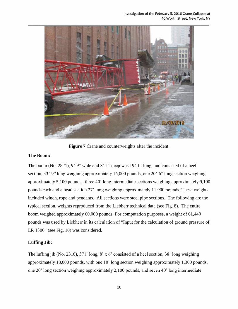
Figure 7 Crane and counterweights after the incident.
The Boom:
The boom (No. 2821), 9’-9” wide and 8’-1” deep was 194 ft. long, and consisted of a heel
section, 33’-9” long weighing approximately 16,000 pounds, one 20’-6” long section weighing
approximately 5,100 pounds, three 40’ long intermediate sections weighing approximately 9,100
pounds each and a head section 27’ long weighing approximately 11,900 pounds. These weights
included winch, rope and pendants. All sections were steel pipe sections. The following are the
typical section, weights reproduced from the Liebherr technical data (see Fig. 8). The entire
boom weighed approximately 60,000 pounds. For computation purposes, a weight of 61,440
pounds was used by Liebherr in its calculation of “Input for the calculation of ground pressure of
LR 1300” (see Fig. 10) was considered.
Luffing Jib:
The luffing jib (No. 2316), 371’ long, 8’ x 6’ consisted of a heel section, 38’ long weighing
approximately 18,000 pounds, with one 10’ long section weighing approximately 1,300 pounds,
one 20’ long section weighing approximately 2,100 pounds, and seven 40’ long intermediate

Investigation of the February 5, 2016 Crane Collapse at 40 Worth Street, New York, NY
_____________________________________________________________________________________
11
sections weighing approximately 4,000 pounds each and a jib head section 35’ long weighing
approximately 5,000 pounds. All sections were steel with round shapes. The following weights
are reproduced from the Liebherr technical data publication (see Fig. 9). The entire jib along
with pendants weighed approximately 54,000 pounds. However, for the purposes of
computations, the weight of 58,490 pounds (see Fig. 10) was indicated by Liebherr in its
calculations of “Input for the calculation of ground pressure of LR 1300”.
Counterweights:
There were eight basic counterweights weighing 22,000 pounds each, six basic counterweights
weighing 11,000 pounds each with a counterweight body of 32,000 pounds. In addition, there
were four counterweights in the body section of the crane, each weighing 31,500 pounds. The
two crawlers weighed 49,200 pounds each.
Figure 8 Boom dimensions.

Investigation of the February 5, 2016 Crane Collapse at 40 Worth Street, New York, NY
_____________________________________________________________________________________
12
Figure 9 Luffing jib dimensions.

Investigation of the February 5, 2016 Crane Collapse at 40 Worth Street, New York, NY
_____________________________________________________________________________________
13
Figure 10 Liebherr input for the calculation of ground pressure of LR 1300.

Investigation of the February 5, 2016 Crane Collapse at 40 Worth Street, New York, NY
_____________________________________________________________________________________
14
3. Data from the Crane’s Computer (CPU data)
The crane was equipped with a computer that recorded operations of the crane. Liebherr
downloaded the data from the crane’s computer, and the data was made available to OSHA by
the New York City District Attorney’s office. A sample page from the CPU data is shown below,
see Fig. 11
The computer time in the CPU data did not correspond to Eastern Standard Time (EST).
However, the incident time of approximately 8:15 a.m. could be related to the corresponding
computer time of 9:29 a.m. when the crane overturned. The data contained hundreds of readings
at intervals of fractions of seconds showing boom angle, luffing jib angle, error messages, if any,
and various other information, e.g. utilization factors, fall back support information, and
information about various switches. Such readings were recorded in multiple lines, each line for
a specific point in time. Each line did not provide all the data; for instance some lines contained
information about boom angle only while others provided jib angles, maximum utilization and
radius only. Selected data are extracted from the CPU output to show the crane boom angle
variations on the day of the collapse and the day before.
Fig. 12 shows selected CPU data on the day of the incident. The boom angles and jib angles are
highlighted. As can be seen, the boom angle was 80° on February 5 at 7:49 a.m. computer time.
Then at 9:28 a.m. computer time, the boom angle was reduced to 69.4° and at computer time of
9:29 a.m., the computer generated an error message. Immediately thereafter, the boom angle
dived to 34.5° with the jib at an angle of 13.9°. Within seconds the boom and jib angles became
0° and the crane overturned and collapsed. The local time was approximately 8:15 a.m.
The Table 1 and the graph (fig. 13) show the boom angle on the day of the incident and the
previous evening. The table shows that the boom angle was approximately 87° on the evening of
February 4, 2016. The last recorded boom angle on February 4 was 87.4° at 6:53 p.m. computer
time. On the morning of the day of the incident, the first recorded boom angle was 80°, an
unexplained variation of 7° from the previous evening. The top ten lines of the following figure
indicating the boom angles suddenly reversed upwards after being on the ground (stack index
262962 to 263026), are not considered reliable. This could have been the result of the
overturning of the base of the crane including the operator’s cabin.

Investigation of the February 5, 2016 Crane Collapse at 40 Worth Street, New York, NY
_____________________________________________________________________________________
15
‘
Figure 11 Sample page from CPU data.

Investigation of the February 5, 2016 Crane Collapse at 40 Worth Street, New York, NY
_____________________________________________________________________________________
16
Prior
ity
Text
Time
Stack
Index
info control input of flap (overtopping guard strut of luffing fly-jib) reports: Flap is
extended -> Error! Angle main boom: 0.0°, luffing fly-jib: 0.0°
2/5/2016 9:29 262961
info fall back support main boom is deactivated, angle main boom: 15.1° 2/5/2016 9:29 262960
error fall back support main boom limit switch is activated, contact of the fall back
support is geometrical not possible, angle main boom: 15.1°
2/5/2016 9:29 262957
info upper limit switch luffing jib deactivated, main boom angle: 18.4, luffing jib angle:
26.6
2/5/2016 9:29 262955
info upper limit switch luffing jib activated, main boom angle: 18.4, luffing jib angle:
26.6
2/5/2016 9:29 262953
info upper limit switch luffing jib deactivated, main boom angle: 18.4, luffing jib angle:
26.6
2/5/2016 9:29 262948
info upper limit switch luffing jib activated, main boom angle: 21.1, luffing jib angle:
27.7
2/5/2016 9:29 262945
info fall back support of the luffing jib snaped in the flap; angle of the luffing jib:
26.3°, engine running: 1 (1=yes/0=no), (in case of 0: maybe ignition turned on in
that second?)
2/5/2016 9:29 262937
info lower limit switch luffing jib activated, main boom angle: 23.4, luffing jib angle:
26.3
2/5/2016 9:29 262936
info upper limit switch luffing jib activated, main boom angle: 23.4, luffing jib angle:
26.3
2/5/2016 9:29 262935
info upper limit switch luffing jib deactivated, main boom angle: 34.5, luffing jib angle:
13.9
2/5/2016 9:29 262931
info upper limit switch luffing jib activated, main boom angle: 34.5, luffing jib angle:
13.9
2/5/2016 9:29 262929
error angle sensor pivot piece and boom head, luffing jib, signals not equal 2/5/2016 9:29 262908
info fall back support main boom is deactivated, angle main boom: 69.4° 2/5/2016 9:28 262907
info fall back support main boom limit switch is activated, angle main boom: 69.4° 2/5/2016 9:28 262906
info fall back support main boom is deactivated, angle main boom: 69.4° 2/5/2016 9:28 262905
info lml utilization less than 110%, maximum utilization: 163.4%, at radius: 105.1m 2/5/2016 9:28 262903
info lml utilization less than 110%, maximum utilization: 112.8%, at radius: 100.1m 2/5/2016 9:19 262898
info lml utilization less than 110%, maximum utilization: 166.8%, at radius: 101.7m 2/5/2016 9:19 262895
info lml utilization less than 110%, maximum utilization: 219.6%, at radius: 104.1m 2/5/2016 9:19 262892
info lml utilization less than 110%, maximum utilization: 182.9%, at radius: 102.9m 2/5/2016 9:19 262889
info lml utilization less than 110%, maximum utilization: 165.7%, at radius: 104.6m 2/5/2016 9:15 262881
info fall back support main boom limit switch is activated, angle main boom: 80.0° 2/5/2016 7:49 262855
CPU data shows main boom angle varying from 80° to 0° on the day of the incident
Figure 12 Main boom angle on the day of the incident.

Investigation of the February 5, 2016 Crane Collapse at 40 Worth Street, New York, NY
_____________________________________________________________________________________
17
Table 1 Data taken from the CPU output
Date Time
Boom
angle
Stack
Index Date Time
Boom
angle
Stack
Index
5-Feb-
16 9:29:42 AM 4.7 263026
4-Feb-
16 6:53:33 PM 87.4 262851
9:29:42 AM 22.6 263006
5:08:12 PM 87 262844
9:29:41 AM 22.9 263000
5:06:46 PM 87 262843
9:29:41 AM 22.9 262998
5:01:30 PM 87.2 262840
9:29:41 AM 56.8 262992
5:01:21 PM 87.2 262839
9:29:41 AM 22.9 262990
4:41:38 PM 87.1 262835
9:29:41 AM 22.8 262988
4:40:25 PM 87 262833
9:29:41 AM 22.8 262985
4:40:23 PM 87.1 262832
9:29:41 AM 45.6 262977
4:40:14 PM 87.1 262831
9:29:41 AM 45.6 262973
4:40:05 PM 87 262830
9:29:40 AM 10 262962
4:40:00 PM 87.2 262829
9:29:40 AM 0 262961
4:39:50 PM 87 262828
9:29:40 AM 15.1 262960
4:39:41 PM 86.9 262827
9:29:40 AM 15.1 262959
4:39:31 PM 87.4 262826
9:29:40 AM 15.1 262957
4:39:25 PM 87.2 262825
9:29:40 AM 18.4 262955
4:39:14 PM 87.3 262824
9:29:40 AM 18.4 262953
4:39:11 PM 87.1 262823
9:29:40 AM 18.4 262952
4:37:27 PM 87.2 262822
9:29:40 AM 18.4 262951
4:37:21 PM 86.9 262821
9:29:40 AM 18.4 262950
4:37:11 PM 87.2 262820
9:29:40 AM 18.4 262948
4:37:06 PM 86.9 262819
9:29:40 AM 21.1 262945
4:20:16 PM 87.1 262818
9:29:40 AM 21.1 262944
4:19:02 PM 87 262817
9:29:40 AM 21.1 262942
4:19:01 PM 87 262816
9:29:40 AM 21.1 262940
4:18:47 PM 87 262815
9:29:40 AM 21.1 262938
4:18:42 PM 87 262814
9:29:40 AM 26.3 262937
4:18:31 PM 87.1 262813
9:29:40 AM 23.4 262936
4:18:25 PM 87 262812
9:29:40 AM 23.4 262935
4:18:15 PM 87 262811
9:29:38 AM 34.5 262931
4:18:08 PM 87.1 262810
9:29:38 AM 34.5 262929
4:17:58 PM 87.1 262809
9:28:49 AM 69.4 262907
9:28:49 AM 69.4 262906
9:28:49 AM 69.4 262905
7:49:56 AM 80 262855
Note: The boom angle when the system was shut down on 4-Feb-16 was 87.4°. On Feb. 5th, the day
of the incident, the main boom angle was at 80° at 7:49 AM and then it became 0° at 9:29 AM.
Boom angle 0° Collapse of crane
Dat
a n
ot
relia
ble
. Bo
om
an
gle
sho
wn
is
pro
bab
ly a
fter
ove
rtu
rnin
g o
f th
e c
ran
e
Investigation of the February 5, 2016 Crane Collapse at 40 Worth Street, New York, NY
_____________________________________________________________________________________
18
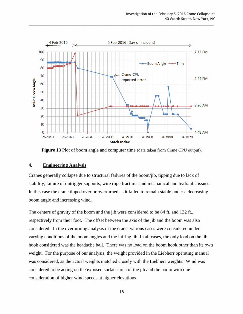
Figure 13 Plot of boom angle and computer time (data taken from Crane CPU output).
4. Engineering Analysis
Cranes generally collapse due to structural failures of the boom/jib, tipping due to lack of
stability, failure of outrigger supports, wire rope fractures and mechanical and hydraulic issues.
In this case the crane tipped over or overturned as it failed to remain stable under a decreasing
boom angle and increasing wind.
The centers of gravity of the boom and the jib were considered to be 84 ft. and 132 ft.,
respectively from their foot. The offset between the axis of the jib and the boom was also
considered. In the overturning analysis of the crane, various cases were considered under
varying conditions of the boom angles and the luffing jib. In all cases, the only load on the jib
hook considered was the headache ball. There was no load on the boom hook other than its own
weight. For the purpose of our analysis, the weight provided in the Liebherr operating manual
was considered, as the actual weights matched closely with the Liebherr weights. Wind was
considered to be acting on the exposed surface area of the jib and the boom with due
consideration of higher wind speeds at higher elevations.

Investigation of the February 5, 2016 Crane Collapse at 40 Worth Street, New York, NY
_____________________________________________________________________________________
19
Wind:
Wind data was obtained from the National Weather Service recorded at four locations, i.e, at
Central Park, at John F Kennedy International Airport, at La Guardia Airport and at Newark
Liberty International Airport. The wind data and station details are presented below.
Table 2 Wind data and station details
Location Elevation
(ft. above sea level) Time
Wind Speed
(MPH)
Wind Gusts
(MPH)
Central Park 130 8:16am 13 22
John F Kennedy
International Airport 11 7:51am 21 30
La Guardia Airport 11 8:17am 17 26
Newark Liberty
International Airport 7 7:51am 20 NA
JFK and Newark Airports reported 20-21 mph wind with gust up to 30 mph while La Guardia
and Central Park reported 13 to 17 mph wind with gust up to 26 mph. The gusts were reported
to be in the range of 22 to 30 mph. Five basic wind speeds were considered, e.g., 20, 22, 25, 26
and 30 mph to analyze the tipping and stability of the crane. The anemometer towers are
typically located at 10 meters (33 ft.) above ground level. The recorded wind speed at 33 ft.
could be misleading as the wind speed would be much higher at the boom and the jib of the
crane, as the crane was approximately 550 ft. tall.
The crane was situated on Worth Street with high-rise buildings of various heights and
configurations located parallel and at right angles to the street, giving rise to wind turbulence,
disturbances and gusts. Other than conducting a wind tunnel test to accurately determine the
wind speeds along the vertical profile of the crane, all methods to compute the wind loads are
approximate but are considered satisfactory for this investigation. The wind’s contribution to
stability proved to be significant in spite of the large weight of the machine and the relatively
small sail area of the steel frame members. The wind profiles considered in the analysis are

Investigation of the February 5, 2016 Crane Collapse at 40 Worth Street, New York, NY
_____________________________________________________________________________________
20
given below, using the logarithmic wind speed profile for the reference wind speed of 20, 22, 25,
26 and 30 mph at the reference elevation of 33 ft. Other methods also yielded similar results.
Figure 14 Wind speed profile
Wind pressure on crane components increases with the increasing wind speed and increasing
height in the ratio of the square of the wind speeds. Compared to the 20 mph wind speed, the
wind pressure on the crane jib and boom increases by 65% and 119% at 25 and 30 mph wind
speeds, respectively. All five speeds were considered in the analysis.
A line diagram of the vertical profile of the crane is shown below, see Fig. 15.
0.0
50.0
100.0
150.0
200.0
250.0
300.0
350.0
400.0
450.0
500.0
0 10 20 30 40 50 60 70 80 90
He
igh
t A
bo
ve G
rou
nd
[FT
]
Wind Speed [MPH]
Vertical Wind Profile
20 mph 22 mph 25 mph 26 mph 30 mph

Investigation of the February 5, 2016 Crane Collapse at 40 Worth Street, New York, NY
_____________________________________________________________________________________
21
Figure 15 Crane vertical profile
Wind loads were computed by the formula p = 0.00256 V2 where p is the wind pressure in
pounds per square foot and V is the wind speed in miles per hour. Other than pendants, the
majority of the structural members of the boom and jib were round shapes to minimize the
effects of wind. A shape factor of 0.5 was used to arrive at the wind loads on round members.
Overturning safety factor:
Generally the factor of safety against overturning varies from 1.0 to 1.33. Liebherr provided a
factor of safety of 1.33 at 360 degrees of swing. The worst scenario for overturning occurs when
the boom is on the side, i.e., at right angles to the main axis of the crane base. In this case, the
boom and the jib were located along the main axis of the base, thus providing a greater margin of
safety. When the factor of safety against overturning approaches 1.0, collapse of the crane
becomes imminent as was the case here.

Investigation of the February 5, 2016 Crane Collapse at 40 Worth Street, New York, NY
_____________________________________________________________________________________
22
Below are the various cases considered with and without the wind and the, related factor of
safety. Boom and luffing jibs were considered to be 194 ft. and 371 ft., respectively. In all cases
a hook load of 2,000 pounds was considered at the luffing jib and at the boom. No other loads
were assumed at the jib and boom blocks.
Table 3 Summary of various cases studied
Case No. Radius (ft.) Boom angle ( °) Jib angle ( °)
CASE_1 296 80.0 45.0
CASE_2 328 80.0 37.5
CASE_3 331 69.4 45.0
CASE_4 345 69.4 41.8
CASE_5 344 65.0 45.0
CASE_6 401 60.0 35.0
CASE_7 405 80.0 0.0
CASE_8 439 69.4 0.0
Case I:
The crane boom is considered at an angle of 80o with the luffing jib at 45
o.
Figure 16 Case I - Crane vertical profile.

Investigation of the February 5, 2016 Crane Collapse at 40 Worth Street, New York, NY
_____________________________________________________________________________________
23
The safety factors (SF) for crane tipping are determined for the conditions without and with wind
loads, as
For condition w/o wind
SF = 1.789
For condition w/ wind
Wind speed, mph 20 22 25 26 30
SF = 1.380 1.315 1.222 1.190 1.073
Case II:
The crane boom is considered at an angle of 80o with the luffing jib at 37.5
o.
Figure 17 Case II - Crane vertical profile.
The safety factors (SF) for crane tipping are determined for the conditions without and with wind
loads, as
For condition w/o wind
SF = 1.627

Investigation of the February 5, 2016 Crane Collapse at 40 Worth Street, New York, NY
_____________________________________________________________________________________
24
For condition w/ wind
Wind speed, mph 20 22 25 26 30
SF = 1.341 1.292 1.220 1.194 1.099
Case III :
The crane boom is considered at an angle of 69.4o with the luffing jib at 45
o.
Figure 18 Case III - Crane vertical profile.
The safety factors (SF) for crane tipping are determined for the conditions without and with wind
loads, as
For condition w/o wind
SF = 1.276
For condition w/ wind
Wind speed, mph 20 22 25 26 30
SF = 1.061 1.024 0.969 0.950 0.877

Investigation of the February 5, 2016 Crane Collapse at 40 Worth Street, New York, NY
_____________________________________________________________________________________
25
Case IV:
The crane boom is considered at an angle of 69.4o with the luffing jib at 41.8
o.
Figure 19 Case IV - Crane vertical profile.
The safety factors (SF) for crane tipping are determined for the conditions without and with wind
loads, as
For condition w/o wind
SF = 1.237
For condition w/ wind
Wind speed, mph 20 22 25 26 30
SF = 1.050 1.017 0.968 0.950 0.884

Investigation of the February 5, 2016 Crane Collapse at 40 Worth Street, New York, NY
_____________________________________________________________________________________
26
Case V
The crane boom is considered at an angle of 65o with the luffing jib at 45
o.
Figure 20 Case V - Crane vertical profile.
The safety factors (SF) for crane tipping are determined for the conditions without and with wind
loads, as
For condition w/o wind
SF = 1.145
For condition w/ wind
Wind speed, mph 20 22 25 26 30
SF = 0.974 0.943 0.898 0.882 0.821

Investigation of the February 5, 2016 Crane Collapse at 40 Worth Street, New York, NY
_____________________________________________________________________________________
27
Case VI
The crane boom is considered at an angle of 60o with the luffing jib at 35
o.
Figure 21 Case VI - Crane vertical profile.
The safety factors (SF) for crane tipping are determined for the conditions without and with wind
loads, as
For condition w/o wind
SF = 0.958
For condition w/ wind
Wind speed, mph 20 22 25 26 30
SF = 0.870 0.853 0.827 0.818 0.780

Investigation of the February 5, 2016 Crane Collapse at 40 Worth Street, New York, NY
_____________________________________________________________________________________
28
Case VII
The crane boom is considered at an angle of 80o with the luffing jib at 0
o.
Figure 22 Case VII - Crane vertical profile.
The safety factors (SF) for crane tipping are determined for the conditions without and with wind
loads, as
For condition w/o wind
SF = 1.317
For condition w/ wind
Wind speed, mph 20 22 25 26 30
SF = 1.243 1.228 1.205 1.196 1.162

Investigation of the February 5, 2016 Crane Collapse at 40 Worth Street, New York, NY
_____________________________________________________________________________________
29
Case VIII
The crane boom is considered at an angle of 69.4o with the luffing jib at 0
o.
Figure 23 Case VIII - Crane vertical profile.
The safety factors (SF) for crane tipping are determined for the conditions without and with wind
loads, as
For condition w/o wind
SF = 1.016
For condition w/ wind
Wind speed, mph 20 22 25 26 30
SF = 0.974 0.966 0.953 0.948 0.927

Investigation of the February 5, 2016 Crane Collapse at 40 Worth Street, New York, NY
_____________________________________________________________________________________
30
Table 4 Summary of results
Case No.
Boom Angle
( o )
Jib Angle ( o )
Wind Load
S.F.
Basic Wind Speed (MPH)
20 22 25 26 30
CASE_1 80.0 45.0 No 1.789
Yes 1.380 1.315 1.222 1.190 1.073
CASE_2 80.0 37.5 No 1.627
Yes 1.341 1.292 1.220 1.194 1.099
CASE_3 69.4 45.0 No 1.276
Yes 1.061 1.024 0.969 0.950 0.877
CASE_4 69.4 41.8 No 1.237
Yes 1.050 1.017 0.968 0.950 0.884
CASE_5 65.0 45.0 No 1.145
Yes 0.974 0.943 0.898 0.882 0.821
CASE_6 60.0 35.0 No 0.958
Yes 0.870 0.853 0.827 0.818 0.780
CASE_7 80.0 0.0 No 1.317
Yes 1.243 1.228 1.205 1.196 1.162
CASE_8 69.4 0.0 No 1.016
Yes 0.974 0.966 0.953 0.948 0.927
Highlighted are the cases where instability is either about to occur or already in the process of
collapse.
It must be noted that the stability of the crane with its pre-incident configuration of the boom and
the jib was largely governed by the angle of the boom, and was less dependent on the angle of
the jib. The above cases indicate a range of factors of safety against overturning with and
without wind. As can be seen, the wind reduces the factor of safety significantly. Case 1, 2 and
7 indicate that if the boom angle was maintained at 80 degrees, there was an adequate factor of
safety even with the prevailing winds. Therefore, the luffing jib could have been lowered to the
ground without any detrimental effect despite the prevailing winds if the boom was maintained at
an angle of 80 degrees. However if the boom angle was lowered to 69.4o, the crane’s stability
was jeopardized in the face of the prevailing winds regardless of the angle of the jib , and the
failure would been imminent as was the actual case. The load chart provided by Liebherr, see
Fig. 27, does not provide any load carrying capacity when the boom angle is lower than 75o with

Investigation of the February 5, 2016 Crane Collapse at 40 Worth Street, New York, NY
_____________________________________________________________________________________
31
a combination of a 194 ft. long boom and a 371 ft. long jib. It must therefore be inferred that the
boom could not be lowered to less than 75 degrees in any event.
Operation of Crane in the event of Wind as per crane manufacturer.
The operator’s manual section 6.7 “Restrictions due to wind” explains the procedure to be
followed in the event of wind.
Figure 24 Operation of crane in the event of wind.
6.7 Restrictions due to wind The current wind speed is shown on the operational screen for lifting operations on
the monitor.
The following three steps describe the procedure in the event of wind:
– Reducing the lifting capacity
– Placing the boom in its parked position
– Laying down the boom
6.7.1 Reducing the lifting capacity The reduction of the lifting capacity for crane operation in the event of wind can be
found in the load chart manual.
6.7.2 Parked positions for boom configurations The parking position of the boom applies up to the maximum wind speed. Above this speed the boom must be set down.

Investigation of the February 5, 2016 Crane Collapse at 40 Worth Street, New York, NY
_____________________________________________________________________________________
32
The crane had a combination of 2821 type main boom and 2316 type luffing jib. The main boom
was 194 ft. (59 m) and the luffing jib was 371 ft. (113 m). The above Fig. 24 is applicable to a
combination of boom and jib where the jib length has a maximum length of 282 ft. The length of
the jib in this instance was 371ft., therefore, the option of a parked position for a jib length of
371 ft. is eliminated. The manufacturer directs the user to lay down the boom and the jib for
more than 292 ft. (89 m) in the event that the wind speed is in excess of the allowable wind
speed, see Fig. 24 above. Work with the crane is then not permitted. The manufacturer’s manual
and documents do not provide a direct reading of the wind speed at which work must be stopped,
and the boom and jib laid down. It, however, provides a range of load carrying capacity at
various wind speeds for different combinations of boom and jib lengths. When the reduction is
100% at a certain wind speed, it must be presumed that the work must be stopped. The reduction
of the lifting capacity is provided in the load chart below. Regardless of the boom length, if the
jib length is between 312 ft. and 371 ft., the load reduction is 100% for wind speed greater than
20 mph (9 m/s), see Fig. 25 below. Although there is a stipulation in the Liebherr document that
if the wind speed falls between the two limits, use the higher wind speed, Liebherr in its letter to
OSHA maintained that 20 mph is the cut-off point.
Figure 25 Operation of crane in the event of wind (from the load chart manual).
Investigation of the February 5, 2016 Crane Collapse at 40 Worth Street, New York, NY
_____________________________________________________________________________________
33
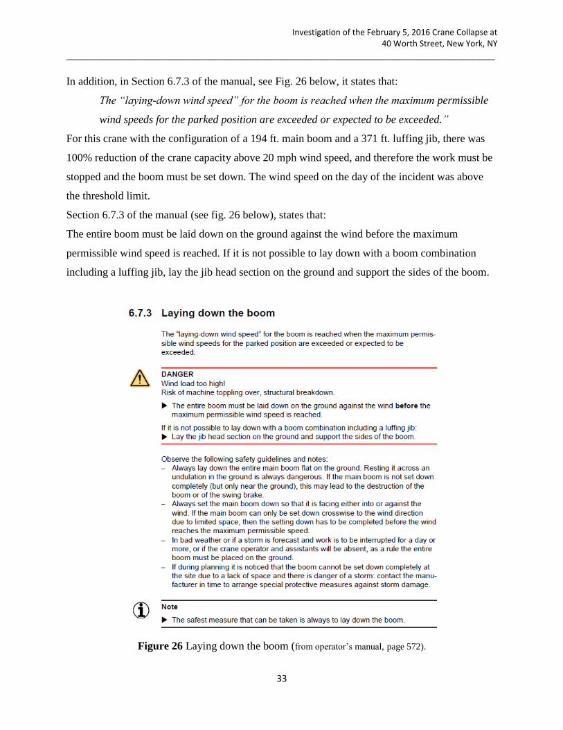
In addition, in Section 6.7.3 of the manual, see Fig. 26 below, it states that:
The “laying-down wind speed” for the boom is reached when the maximum permissible
wind speeds for the parked position are exceeded or expected to be exceeded.”
For this crane with the configuration of a 194 ft. main boom and a 371 ft. luffing jib, there was
100% reduction of the crane capacity above 20 mph wind speed, and therefore the work must be
stopped and the boom must be set down. The wind speed on the day of the incident was above
the threshold limit.
Section 6.7.3 of the manual (see fig. 26 below), states that:
The entire boom must be laid down on the ground against the wind before the maximum
permissible wind speed is reached. If it is not possible to lay down with a boom combination
including a luffing jib, lay the jib head section on the ground and support the sides of the boom.
Figure 26 Laying down the boom (from operator’s manual, page 572).

Investigation of the February 5, 2016 Crane Collapse at 40 Worth Street, New York, NY
_____________________________________________________________________________________
34
Load chart for combination of 194 ft. long boom and 371 ft. jib
Reproduced below is the load chart from Liebherr indicating the loads that can be safely hoisted
with boom angles of 88, 83 and 75 degrees. Loads chart are not provided for boom angles lower
than 75 degrees. It is therefore presumed that a boom with the given configuration of a boom
length of 194 ft. and a jib length of 371 ft. could not be positioned lower than 75 degrees. In this
configuration, given the boom angle of 75 degrees, the jib angle could vary from 65 to 40
degrees. At the jib angle of 40 degrees and the boom angle of 75 degrees, the capacity of the
crane is just 2,300 pounds including the weight of the block, etc.
Figure 27 Load chart (taken from MRA Engineering report).

Investigation of the February 5, 2016 Crane Collapse at 40 Worth Street, New York, NY
_____________________________________________________________________________________
35
MRA Engineering, P.C.
As mentioned earlier, Galasso Trucking & Rigging Inc. retained a consultant, MRA Engineering,
P.C. to prepare an application for approval by New York City indicating the type and size of the
crane to be used in the project. Based upon its computations, MRA prepared an application
which was approved by the NYC. The application ran into several pages, proposing the subject
crane to be used with specified lengths of the boom and the jib. The application also contained
the following instructions:
“Cranes to be stowed overnight or in severe weather conditions as per manufacturer’s
recommended procedures found in the operator’s crane manual.” MRA also provided a sketch
showing the manner in which the crane needed to be stowed, although a few details like the
angle of the boom and the jib are lacking. The sketch, however, provides an overall arrangement
for stowing the crane overnight and during severe weather conditions. MRA’s above instruction
contained a directive “as per manufacturer’s recommended procedures found in the operator’s
crane manual”. However, Liebherr in its manual did not recommend that the crane be stowed or
parked in the manner suggested by MRA, but rather they instructed the user of the crane, due to
the long length of the jib, to lay down the crane instead of jack knifing it, in the event the wind
speed is anticipated to be in excess of 20 mph. Bay Crane, which owned the crane, requested
Liebherr, after the incident, to determine whether the subject crane could be jack knifed under
severe weather conditions instead of laying it down on the ground. Liebherr stated in its email of
February 5, 2016, the day of the incident, that Liebherr could make such a determination if asked
by the “customer” with the specific configurations of the boom and the jib. In an email of
February 5, 2016, after the incident, Liebherr stated that the subject crane could be parked in a
jack knife position up to a maximum wind speed of 67 mph provided certain conditions were
met. This determination by Liebherr overrides the instructions provided in the Liebherr manual
and provides alternate options to the user and is in general agreement with MRA’s instructions to
Galasso, although MRA’s instructions lacked information about the angle of the boom and the
maximum wind speed.
At the end of the day on February 4, 2016, the weather forecast for the wind for the night and the
next morning were reportedly known to Galasso Trucking & Rigging Inc. but no decision was
taken to lay down the crane. That proved to be a grievous error.

Investigation of the February 5, 2016 Crane Collapse at 40 Worth Street, New York, NY
_____________________________________________________________________________________
36
Figure 28 Stow Plan from the consultant
February 4 and 5, 2016
The day before the incident, February 4, 2015, CPU data indicates that the boom for the entire
day remained at approximately 87 degrees, and the jib at 78 degrees. On February 5, 2016, the
day of the incident, the first reading of the boom angle at the computer time of 7:49 a.m. is
indicated at 80 degrees by the CPU data. The change of 7 degrees in the boom angle from the
previous evening to the next morning is not explained. No meaningful activity occurred from
7:49 a.m. until 9:14 a.m (computer time). For the next 14 minutes, i.e., 9:14 a.m. to 9:28 a.m.,
the jib angle varies from 34 to 39 degrees with the radius ranging from 329 to 344 ft., assuming
that the boom remained at 80 degrees. For these 14 minutes, it is believed that the stability of the
crane was not jeopardized even in prevailing winds because the boom angle was maintained at
80 degrees. CPU data, however, indicate that there were multiple instances in these 14 minutes
when the crane was over 110% of its capacity momentarily but immediately returned to 110% or
below. At approximately 9:28 a.m., the crane operator suddenly lowered the boom angle to 69.4

Investigation of the February 5, 2016 Crane Collapse at 40 Worth Street, New York, NY
_____________________________________________________________________________________
37
degrees at which time the stability of the crane was lost and tipping began until the entire crane
and the jib were on the ground. CPU data indicates a decreasing angle of the boom until it
reached zero degrees. We cannot say with certainty whether the crane operator knowingly
lowered the boom angle to 69.4 degrees or if it was a case of human error on the part of the crane
operator. The crane operator, however, is reported to have said in several interviews that he
maintained the boom angle at 80 degrees and did not lower it to 69 degrees. There are indications
in the CPU data that an attempt was made during the ensuing collapse to raise the jib but it had
little impact because the boom was dropping too fast. CPU data indicate that the jib was raised
from 13 to 26 degrees during the collapse but to no avail.
It is understood that in the near future the length of the wire ropes would be field measured in the
Brooklyn Yard where the remnants of the crane have been stored to calculate the angle of the
boom and the jib immediately preceding the collapse. That field measurement had not been done
at the time this report was completed.
A review of videos taken during the collapse of the crane by amateur videographers publicly
available on youtube.com indicates that the jib was at approximately 45 degrees and the boom
was at approximately 70 degrees at the time of the collapse.

Investigation of the February 5, 2016 Crane Collapse at 40 Worth Street, New York, NY
_____________________________________________________________________________________
38
5. Conclusions
1. The crane was not stowed/parked overnight on the evening of February 4, 2016, as
per the instructions of the consultant, MRA Engineering, retained by Galasso
Trucking & Rigging, Inc. This contributed to the collapse.
2. Liebherr’s manual recommends that the crane be laid on the ground when the wind is
forecast to be above 20 mph. The crane was not laid down during the night between
February 4 and February 5, 2016 although Galasso knew that the wind would be
severe during the night and the early morning.
3. Crane CPU retrieved after the incident indicated that the boom angle of the crane was
lowered to 69.4 degrees at or near the time of the collapse in violation of the
manufacturer’s manual. This contributed to the collapse. Crane in the present
configuration has no load carrying capacity below the boom angle of 75 degrees.
Crane could be operated in wind not exceeding 20 mph and at a boom angle not lower
than 75 degrees. In the event wind exceeds 20 mph, crane must be laid down. The
stability of the crane was highly sensitive to lower boom angle.
4. After the incident, Bay Crane, which owned the crane, asked the crane manufacturer,
Leibherr to determine the “Jack Knife” position of the crane in the event of high
winds. A Jack Knife position was not an option provided by Liebherr in its manual
unless specifically computed and determined by Liebherr on a case-by-case basis.
This inquiry should have been made before the incident.
5. The collapse of the crane occurred when the boom of the crane was lowered to an
angle of less than 75 degrees in a prevailing wind contrary to the manufacturer’s
instructions. It is believed that the crane operator lowered the boom to around 70
degrees.
6. Liebherr’s crane manuals for the operators and users of the crane were deficient
because the procedure for laying down cranes with a luffing jib, 371 ft. long and a
boom 194 ft. long lacked clarity. In the interest of job safety, Liebherr must add a
section to its manuals with clear instructions on details for the proper way to lay down
the boom and the jib in the event of high winds to avoid instability.

Investigation of the February 5, 2016 Crane Collapse at 40 Worth Street, New York, NY
_____________________________________________________________________________________
39
APPENDIX
(Taken from MRA application CN#1157/15)

Investigation of the February 5, 2016 Crane Collapse at 40 Worth Street, New York, NY
_____________________________________________________________________________________
40

Investigation of the February 5, 2016 Crane Collapse at 40 Worth Street, New York, NY
_____________________________________________________________________________________
41

Investigation of the February 5, 2016 Crane Collapse at 40 Worth Street, New York, NY
_____________________________________________________________________________________
42

Investigation of the February 5, 2016 Crane Collapse at 40 Worth Street, New York, NY
_____________________________________________________________________________________
43

Investigation of the February 5, 2016 Crane Collapse at 40 Worth Street, New York, NY
_____________________________________________________________________________________
44

Investigation of the February 5, 2016 Crane Collapse at 40 Worth Street, New York, NY
_____________________________________________________________________________________
45

Investigation of the February 5, 2016 Crane Collapse at 40 Worth Street, New York, NY
_____________________________________________________________________________________
46