2006 Symposium on Room Temp. Detectors Page 1 of 40
Design and performance of the X-123 compact X-ray and Gamma-ray
spectroscopy system
R. Redus, A. Huber, J. Pantazis, T. Pantazis, D. Sperry
Amptek, Inc14 DeAngelo Dr, Bedford MA 01730
This Web presentation is an extended version of the paper presented at the 2006 Room Temperature Semiconductor Detector Workshop, at the IEEE Nuclear Science Symposium
2006 Symposium on Room Temp. Detectors Page 2 of 40
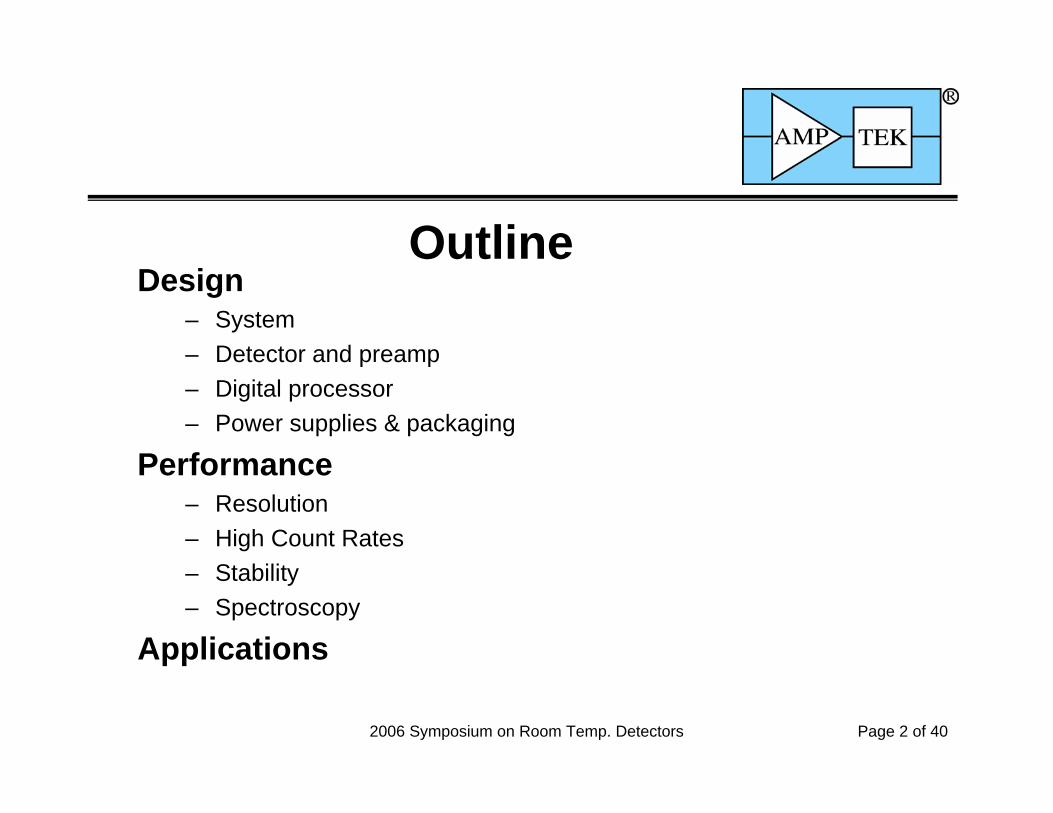
OutlineDesign
– System– Detector and preamp– Digital processor– Power supplies & packaging
Performance– Resolution– High Count Rates– Stability– Spectroscopy
Applications

Page 3 of 40
X123 Design
Compact integrated system– Detector and preamplifier
Detector thermoelectrically cooled
– Digital pulse processor with shaping amplifier and MCA
– All power supplies
– Small size7 x 10 x 2.5 cm3 (2.7 x 3.9 x 1 in3)
– Low power (1.2W)– Light weight (180 g or 6.3 oz)– Simple to operate
• USB communications• +5VDC
Detector
Preamp
DigitalProcessor
Power Supply(bottom board)
ConnectorsUSB & Power

Page 4 of 40
X123 Design
Block diagram of X123 (and related systems)– Complete spectroscopy system: detector, preamp, digital processor
(with shaping, MCA, and logic), comm ports, power supplies, packaging– Same building blocks as Amptek’s DP4 and PX4
Animation shows relationship between Amptek’s digital processing products– Detector options include Si-PIN, CdTe, and CdTe-stack
Detector Preamplifier AnalogPrefilter ADC Digital Pulse
Shaper
PulseSelection
Logic
HistogramLogic Microcontroller Serial
Interface Computer
AuxOutputs
HighVoltageSuply
ThermoelectricCooler Supply
LowVoltageSupplies
+5V DC
X123

2006 Symposium on Room Temp. Detectors Page 5 of 40
X123 Design
X123, PX4, DP4– All are complete spectroscopy systems– All share detectors, digital processing,
other core technologies– Targeted at different applications
PX4 and XR100 for benchtop & laboratory
DP4 and PA210 for embedding in instruments
X123 for compact, packaged system

Page 6 of 40
X123 Detectors
Thermoelectrically Cooled Solid State Detector
• Reasons for thermoelectric cooling– Reduces shot noise and thermal noise– For CdTe, allows higher bias– Cooling invisible to user
• Cooler achieves >80˚C differential– Now using 2 stage coolers in all products– 215K for lab use– 240K for field use (at ambient of 45˚C)
• FET and feedback components on cooler– Leakage currents as low as 5 fA– Low stray capacitance, reduced EMI pickup

Page 7 of 40
X123 Detectors
Three detectors for different energy ranges– Low energies (X-rays)
• Si-PIN detector• Recommended from 1.5 to 25-40 keV• Resolution: 150 eV FWHM at 5.9 keV
– Medium energies• CdTe diode• Recommended from 25-40 to 100 keV• Resolution: 600 eV FWHM at 59.5 keV
– Gamma-Rays• CdTe diode stack• Recommended from 100 to 600 keV• Resolution: 6 keV at 662 keV
– All based on thermoelectric cooling– All are compatible with X123
Plot compares a 57Co spectrum from Si-PIN and CdTe detectors: the Si-PIN has much better resolution but above 30 keV much lower sensitivity.

Page 8 of 40
X123 Detectors
Low energy X-rays– Detector : Si-PIN– Thickness: 200 to 1000 μm– Area: 5 to 25 mm2
– Feedback: Capacitive reset into the HV node
– Be window: 0.5 to 4 mil– Internal multilayer collimator
Prevents interactions near guard rings
– Best resolution 149 eV FWHMENC = 100 eV FWHM ⇒ 12 electron rmsMeasured with 6 mm2 x 500 μm detector
at 215K and 20 μsec shaping time
ResetCircuit
+VL
Rd
FETDetector
VbiasCf
OutputThermoelectric Cooler
0 1 2 3 4 5 6 7 8Energy (keV)
Cou
nts
55Fe Spectrum6 mm2 x 500 μm detector
Page 9 of 40
X123 Detectors
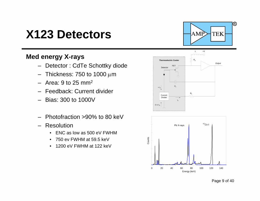
Med energy X-rays– Detector : CdTe Schottky diode– Thickness: 750 to 1000 μm– Area: 9 to 25 mm2
– Feedback: Current divider– Bias: 300 to 1000V
– Photofraction >90% to 80 keV– Resolution
• ENC as low as 500 eV FWHM• 750 ev FWHM at 59.5 keV• 1200 eV FWHM at 122 keV
+VL
Rd
FETDetector
Cf
OutputThermoelectric Cooler
RfCurrentDivider
iR
α iR
(1-α) iR
0 20 40 60 80 100 120 140Energy (keV)
Cou
nts
57Co ΗPb X-rays

Page 10 of 40
X123 Detectors
Gamma-rays– Detector : CdTe stack
• Multiple planar elements• Summed into single preamp• Sensitivity arises from entire volume• Max charge transport length 0.75 mm• Operates like single detector
– Thickness: 2.25 or 3.75 mm– Area: 25 mm2
– Feedback: Resistive– Bias: 1 to 1.4 kV
<1% FWHM at 662 keV
Feedback
ThermoelectricCooler
Detector Elements (three illustrated)
HVbias
To XR100Preamp
0 100 200 300 400 500 600 700Energy (keV)
Cou
nts
137CsUO3

Page 11 of 40
Energy (keV)
1 10 100 1000
Inte
ract
ion
Prob
abili
ty
0.01
0.1
1
O F NeNaMgAl Si P S Ar Ca Ti CrFeNiZnGeBr Sr Mo AgSbBa TaAuPb U Fm
680 μm Si-PIN
500 μm Si-PIN1 mil Be window
200 μm (active) Si-PIN0.5 mil Be window
750 μm CdTe4 mil Be window
3.75 mm CdTe
2.25 mm CdTe
1 mm CdTe
Photoelectric Interactions
1000 μm Si-PIN
X123 Detectors
Plot compares intrinsic efficiency of the detectors. At low energies, the Be window limits sensitivy. The Si-PIN have good efficiency to 30 keV, CdTe to 100 keV, and the CdTe-stack to 500 keV.

Page 12 of 40
X123 Detectors
Recent Detector Developments– Cooler achieves >80˚C differential
• 2 stage coolers in all products• 215K for lab use, 240K for field use (at ambient of 45˚C)
– Thicker active depth for Si-PIN• 1000 μm, fully depleted, with areas of 7 and 25 mm2
• Resolution 185 eV FWHM
– Si-PIN with internal multilayer collimator• Collimator prevents interactions near guard rings and outer edge• Multilayer design prevents characteristic X-rays contaminating signal
Work in Progress– Si drift diodes
• Will increase count rates to reduce measurement time
– Reset preamp for CdTe• Will combine lowest noise with good count rate stability
Page 13 of 40
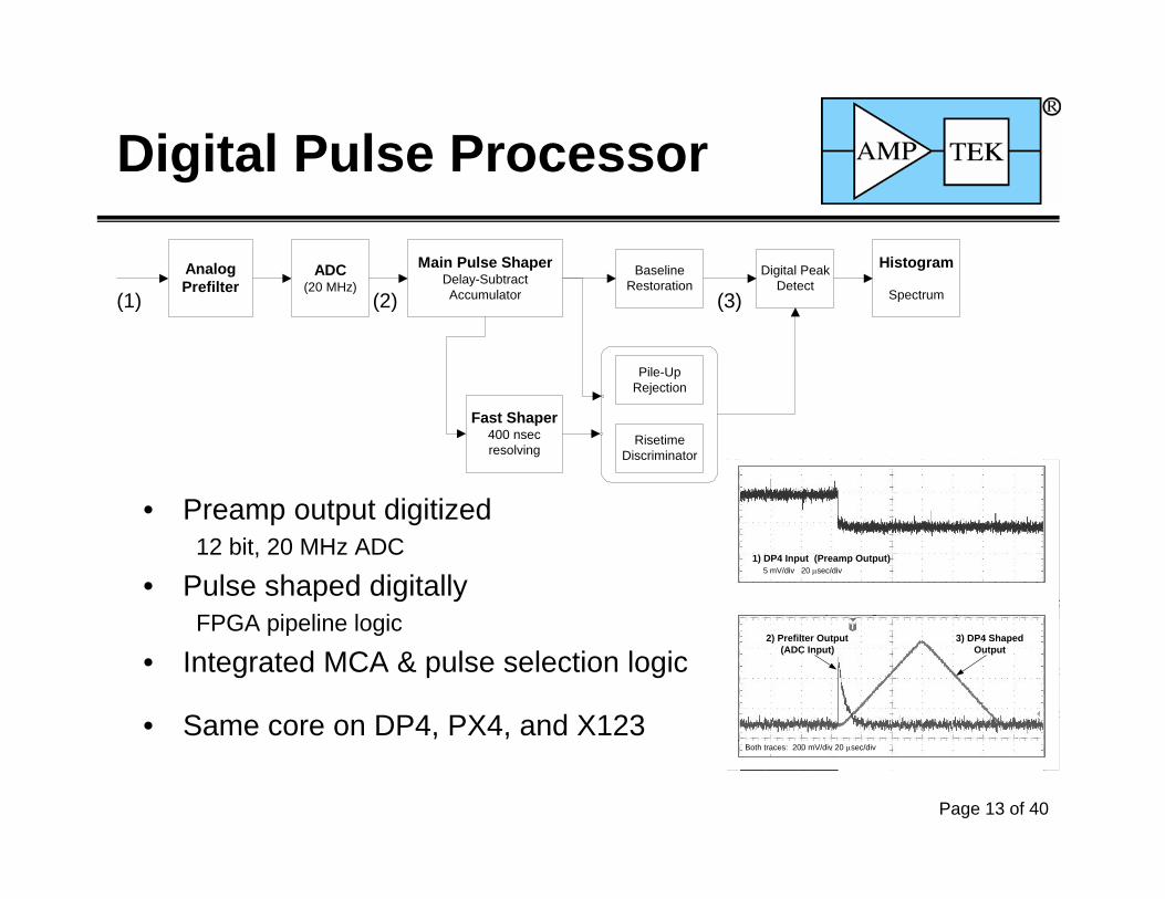
1) DP4 Input (Preamp Output) 5 mV/div 20 μsec/div
Both traces: 200 mV/div 20 μsec/div
2) Prefilter Output(ADC Input)
3) DP4 ShapedOutput
Digital Pulse Processor
AnalogPrefilter
ADC(20 MHz)
Main Pulse ShaperDelay-SubtractAccumulator
Pile-UpRejection
Digital PeakDetect
Histogram
Spectrum
Fast Shaper400 nsecresolving
BaselineRestoration
RisetimeDiscriminator
• Preamp output digitized12 bit, 20 MHz ADC
• Pulse shaped digitallyFPGA pipeline logic
• Integrated MCA & pulse selection logic
• Same core on DP4, PX4, and X123
(1) (2) (3)

2006 Symposium on Room Temp. Detectors Page 14 of 40
Digital Pulse Processor
Advantages of digital processing– Flexible
• Many shaping times: 24 log steps from 0.8 to 102 μsec peaking• Adjustable settings for BLR, RTD, etc• All adjustments are in s/w, via serial connection
– Faster than analog • No dead time for pulse digitization• Finite Impulse Response improves baseline stability• Symmetric shape enhances throughput
– Pulse shape closer to optimum for signal to noise– Improved stability and reproducibility

2006 Symposium on Room Temp. Detectors Page 15 of 40
Digital Pulse ProcessorTrapezoidal Pulse Shape
– No long tail so reduced pile-up– Finite impulse response reduces
baseline shifts– Symmetry reduces PUR interval
Dead time 1.25 τpeak+τflat
– Improved ENC for same pulse duration (FWHM)
Fast Channel– 600 nsec resolving time– Used for
• Pile-up rejection,• Risetime discrimination• Measurement of incoming count rate
0.0E+00 1.0E-06 2.0E-06 3.0E-06 4.0E-06 5.0E-06 6.0E-06 7.0E-06 8.0E-06Time (sec)
Vol
tage
(nor
mal
ized
)
Pulse Duration (FWHM)
Digital Dead Time
Fast Channel pulse pair resolving time
Digital (Trapezoidal)
Analog (Quasi-Triangular)
1.0 10.0 100.0Peaking Time ( sec)
Equivalent Shaping Time ( sec)0.45 4.5 45
2006 Symposium on Room Temp. Detectors Page 16 of 40
Digital Pulse Processor
Digital processing features– Gain
• Coarse gain range x11 to x110 (4 ranges)PX4 has larger coarse gain range, fully overlapping
• Fine gain range 0.75 to 1.25, 10 bit resolution• All gain changes software selectable over serial bus
– System Conversion Gain• For Si-PIN at 1k channels, 7 to 110 eV/channel ⇒ 7 to 110 keV full scale• For CdTe, 20 to 310 eV/channel ⇒ 20 to 310 keV full scale• For CdTe stack, 50 to 3100 eV/channel ⇒ 50 to 3100 keV full scale
– Baseline Restoration• Asymmetric algorithm stabilizes negative noise peaks• Software selectable parameters (64 settings) to tune for application

2006 Symposium on Room Temp. Detectors Page 17 of 40
Digital Pulse Processor
MultiChannel Analyzer Features– MCA Performance
• Commandable to 256, 512, 1024, 2048, 4096k, 8192 channels. • 3 bytes (24 bits) per channel - 16.7M counts • Minimum Acquisition Time < 10 msec • Data transfer time for 1k channels in 10 msec (USB) or 500 msec (RS-232) • Conversion time: None, part of digital pipeline
– Acquisition Modes• Standard MCA Mode: Integrated pulse height spectrum• Delta Mode: Pulse height spectrum from most recent 1 sec acquisition• Repetitive Mode: After each acquisition, saves data to file and then restarts.• MCS Mode: Each channel has number of counts in a time bin, >10 msec per bin
– Other features• Presets: Time, total counts, counts in an ROI, counts in a channel• External controls: Gate and buffer select inputs

2006 Symposium on Room Temp. Detectors Page 18 of 40
Digital Pulse ProcessorCommand and Control
– Software control over serial interfaces• Sends commands, starts and stops acquisition• Reads out and displays spectra and count rates
– Protocols supported• RS232 and USB standard• Can be tailored for Ethernet• I2C and μP pins for direct h/w interfaces
– Software• Amptek’s standard ADMCA software for data
acquisition and control• Interface to with analysis packages
(XRF-FP available from Amptek)• Library (DLL) of drivers for custom software
2006 Symposium on Room Temp. Detectors Page 19 of 40
Digital Pulse ProcessorX123 Outputs
– Primary output is the spectrum• Packet of spectral data• Typically 1k or 2k channels, updated 1 Hz
– Secondary output is oscilloscope display• Captured waveform sent over serial interface• Computer displays waveform, for setup and debugging
– Other outputs available on digital processor board• Standard outputs on DP4, PX4. X123 requires custom connector• Analog outputs: shaped pulse, ADC input, fast pulse, test pulser• Digital outputs: Timing trigger, reset flag, pile-up flag, peak flag, etc• Eight single channel analyzer outputs (LLD, ULD set in software)

2006 Symposium on Room Temp. Detectors Page 20 of 40
X123 Power Design
Architecture– Multiple switching supplies– Low voltages: +3.3V digital, +/-5V analog, +/-8V preamp
Standard, commercial PWM supplies– High voltage: +100 to +1500VDC at microamps
Switch mode supply with Cockroft-Walton– Cooler supply: Closed loop regulation of temperature
Commercial PWM supply with temperature feedback
Configurations– X123: Output voltages set by internal jumpers and pots– PX4: Voltages set by serial command
2006 Symposium on Room Temp. Detectors Page 21 of 40
X123 Power Design
Input– +5VDC nominal– Actual range is 4V to 6V for battery operations– Typical steady state 1.2W (240 mA at 5V)– First minutes, 1.8W (360 mA) until detector is cooled
Power Budget– 0.4W for Peltier cooler (typical steady state at 25˚C)– 0.4W for digital processor– 0.2W for analog circuits– 0.2W for power supplies

2006 Symposium on Room Temp. Detectors Page 22 of 40
X123 Packaging
Packaging is critical!• Charge sensitive preamp, with noise of
12 e- rms, located with cm of 0.3A switching supply
• Must remove 0.5W from detector with minimal ΔTambient
• Machined Al box for EMI, thermal• Careful grounding, layout, and shielding
• Connections– USB, serial, power standard– Others available
• Mounting kit shown

2006 Symposium on Room Temp. Detectors Page 23 of 40
X123 Resolution
Si-PIN 55Fe spectra – Best resolution 149 eV @ 5.9 keV
CdTe spectra– Resolution 0.75 keV @ 59.5 keV
CdTe stack spectra– Resolution 5 keV @ 662 keV
0 20 40 60 80 100 120 140Energy (keV)
Cou
nts
57Co ΗPb X-rays
0 1 2 3 4 5 6 7 8
Energy (keV)
Cou
nts
55Fe Spectrum6 mm2 x 500 m detector
0 100 200 300 400 500 600 700Energy (keV)
Cou
nts
137CsUO3

2006 Symposium on Room Temp. Detectors Page 24 of 40
X123 Resolution
Si-PIN Noise Components– Typical results with a 13mm2 detector– Series noise dominates below 25 μsec peaking time– Parallel noise unimportant– Fano broadening dominates >10 keV
100
1000
1 10 100Peaking Time (usec)
Res
olut
ion
(eV
FW
HM
)
Series noise1/f noise
Resolution at 5.9 keVElectronic Noise

2006 Symposium on Room Temp. Detectors Page 25 of 40
X123 Resolution
CdTe Noise Components– Typical results with a 25 mm2 x0.75 mm detector– Noise corner near 6.4 μsec peaking time– Noise dominates below 30-50 keV– Hole tailing dominates above this
1.0E-01
1.0E+00
1.0E+01
1.0E-01 1.0E+00 1.0E+01 1.0E+02Peaking Time (msec)
Res
olut
ion
(keV
FW
HM
)
122 keV
59.5 keV
14.4 keV
Electronic Noise
CdTe 25mm2 x 0.75 mm500V bias, 230K
2006 Symposium on Room Temp. Detectors Page 26 of 40
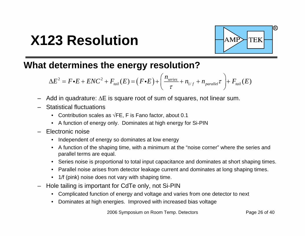
X123 ResolutionWhat determines the energy resolution?
– Add in quadrature: ΔE is square root of sum of squares, not linear sum.– Statistical fluctuations
• Contribution scales as √FE, F is Fano factor, about 0.1• A function of energy only. Dominates at high energy for Si-PIN
– Electronic noise• Independent of energy so dominates at low energy• A function of the shaping time, with a minimum at the “noise corner” where the series and
parallel terms are equal. • Series noise is proportional to total input capacitance and dominates at short shaping times.• Parallel noise arises from detector leakage current and dominates at long shaping times.• 1/f (pink) noise does not vary with shaping time.
– Hole tailing is important for CdTe only, not Si-PIN• Complicated function of energy and voltage and varies from one detector to next• Dominates at high energies. Improved with increased bias voltage
( )2 21/( ) ( )series
tail f parallel tailnE F E ENC F E F E n n F Eτ
τ⎛ ⎞Δ = + + = + + + +⎜ ⎟⎝ ⎠
i i

2006 Symposium on Room Temp. Detectors Page 27 of 40
X123 Sensitivity
Si-PIN Sensitivity– For Si-PIN detectors, sensitivity
vs. resolution trade-off – 6 mm2 x 500 μm best resolution– 25 mm2 x 500 μm large area– 13 mm2 x 1000 μm has sensitivity
to higher energies
– Must be matched to application

2006 Symposium on Room Temp. Detectors Page 28 of 40
X123 High Count Rates
Dead Time and Throughput Different from Analog– In analog, “dead time” specified is for peak digitization.– In digital, there is no dead time for this, only for pulse overlap ⇒ much shorter
dead time and so higher throughput– In digital, pulse is symmetric and timing well defined ⇒ shorter and better known
dead time intervals.– In analog, fast signal used to detect pile-up but fast rate not recorded. In digital,
directly measure the fast rate ⇒ more accurate correction.
Pulse dead time: τpeak
Pile-up reject interval: 2*(1+3/8)τpeak
Fast channel resolving time: 400 nsec

2006 Symposium on Room Temp. Detectors Page 29 of 40
X123 High Count Rates
Throughput– Much better than analog system for same τpeak
– Measured results matches equations very well– Fast channel permits direct dead time correction
( )( )( )( )( )( )
-
- 2.375
e PUR Off
e PUR On
Dead Time Correction1
In Peak Flat
In Peak Flat
ROut In
ROut In
FASTIn
Fast Fast
R R
R R
RRR
τ τ
τ τ
τ
+
+
=
=
=−

2006 Symposium on Room Temp. Detectors Page 30 of 40
X123 High Count Rates
Spectral performance at high rates– We recommend operation <50% dead time– Baseline shifts <0.2% to 50% dead time– Resolution changes similarly
– Spectra here are up to 70% dead time– Double peaks visible to 95% dead time
0 2 4 6 8 10 12 14Energy (keV)
Nor
mal
ized
Cou
nts
0 2 4 6 8 10 12 14Energy (keV)
Nor
mal
ized
Cou
nts
5 5.5 6 6.5 7Energy (keV)
Nor
mal
ized
Cou
nts
95%
96%
97%
98%
99%
100%
101%
0% 20% 40% 60% 80% 100%Dead Time Fraction (%)
Cen
troid
(Nor
mal
ized
)
4.8us
9.6us

2006 Symposium on Room Temp. Detectors Page 31 of 40
X123 Stability
Drift over time– Top plot shows X123-Si data– Bottom plot shows X123-CdTe– Gain fluctuations consistent with
temperature coefficient• 60 ppm/˚C for Si-PIN• 30 ppm/˚C for CdTe
– Count rate follows decay
– PX4 data taken for 1 month– No long term drift observed– Slope within std dev of zero
4.45E+05
4.55E+05
4.65E+05
4.75E+05
9/25 9/26 9/27 9/28Date and Time
Net
Are
a (c
ount
s)
5.84
5.86
5.88
5.90
5.92
5.94
Cen
troid
(keV
)
Centroid1.7 eV (0.03%) rms
Net Area
55Fe decay
7.80E+04
8.05E+04
8.30E+04
8.55E+04
8.80E+04
10/6 12:00 10/7 12:00 10/8 12:00 10/9 12:00 10/10 12:00
Date and Time
Phot
opea
k C
ount
s
121.25
121.50
121.75
122.00
122.25
Cen
troi
d (k
eV)
Centroid15 ev rms, tracks at 30 ppm/°C
Photopeak Counts
57Co decay
2006 Symposium on Room Temp. Detectors Page 32 of 40
X123 Applications
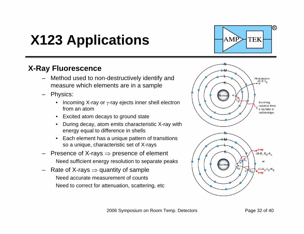
X-Ray Fluorescence– Method used to non-destructively identify and
measure which elements are in a sample– Physics:
• Incoming X-ray or γ-ray ejects inner shell electron from an atom
• Excited atom decays to ground state• During decay, atom emits characteristic X-ray with
energy equal to difference in shells• Each element has a unique pattern of transitions
so a unique, characteristic set of X-rays– Presence of X-rays ⇒ presence of element
Need sufficient energy resolution to separate peaks– Rate of X-rays ⇒ quantity of sample
Need accurate measurement of countsNeed to correct for attenuation, scattering, etc

2006 Symposium on Room Temp. Detectors Page 33 of 40
X123 Applications
X-Ray Fluorescence: Sample Spectra– Typical result for lead– 88 keV incident photons excite sample
• Some scattered photons reach the detector• Lead K-shall has 88 keV binding energy, so
photoelectrons are ejected• Decays from L shells (13-15 keV) lead to
characteristic X-ray emissions at 72, 75, and 85 keV
• Vacancies in L shells are filled by transitions from M shells
• Generates characteristic X-rays at 10, 12, and 15 keV
– No damage to sample– Penetrates beyond surface layers– Rapid and accurate

2006 Symposium on Room Temp. Detectors Page 34 of 40
X123 Applications
Sample Spectrum– Used Amptek XR100, not X123– Taken by Mars Pathfinder
– Spectrum shows peaks present in sample and relative areas
– Yields elemental composition of Martian rocks

2006 Symposium on Room Temp. Detectors Page 35 of 40
X123 Applications
ROHS Verification(Reduction of Hazardous Substances)
– EU requires commercial electronics to be free of lead, cadmium, mercury, etc. as of 7/06
– OEMs need to verify compliance of vendors and suppliers
– X123 Si-PIN can reliably quantify the critical elements
– Compact packaging, easy connections provide simple, COTS solution for end users

2006 Symposium on Room Temp. Detectors Page 36 of 40
X123 Applications
Art and Archeology– XR100 currently used for XRF analysis– X123 provides same performance in much
more compact form
XRF of Michelangelo’s David

2006 Symposium on Room Temp. Detectors Page 37 of 40
X123 Applications
Industrial process control– XRF provides key quality
measurements– X123 permits simple, integrated
solution for end users
2006 Symposium on Room Temp. Detectors Page 38 of 40
X123 Applications
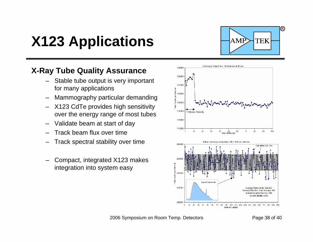
X-Ray Tube Quality Assurance– Stable tube output is very important
for many applications– Mammography particular demanding– X123 CdTe provides high sensitivity
over the energy range of most tubes– Validate beam at start of day– Track beam flux over time– Track spectral stability over time
– Compact, integrated X123 makes integration into system easy

2006 Symposium on Room Temp. Detectors Page 39 of 40
X123 Applications
Radioistope identification– X123 CdTe-Stack– Good energy resolution to 750 keV– Complements higher sensitivity
detectors such as NaI(Tl)– Small size, low power, simple
interface simplify system integrationEnergy (keV)
10 100 1000
Cou
nts
1
10
100
1000
10000
241Am 57Co 133Ba 137Cs 60Co
Fe Kα6.4 keV
137Cs γ662 keV
133Ba γ356 keV
133Ba γ303 keV
60Co γ1.17 MeV1.33 MeV
57Co γ122 keV
241Am γ59.5 keV
Np Lα13.9 keV

2006 Symposium on Room Temp. Detectors Page 40 of 40
Conclusions– Successfully integrated Peltier cooled detectors, digital pulse
processing, and power supplies into a compact package– Works well for Si-PIN, and for 1 mm CdTe, and for CdTe stacks
to cover a wide energy range– Provides high resolution of analog benchtop systems– Digital processor provides much higher throughput and stability
than analog benchtop system– Compact size, low power, and simple interface simplify system
integration for the end user
– For more information, go to www.amptek.com
X123
Recommended