Service Manual
D1 High Power Open Circuit PumpsSize 130/145/193/260
www.danfoss.com
Revision history Table of revisions
Date Changed Rev
October 2019 Fixed EDC control adjustments for clarity 0301
August 2019 Fixed typo 0202
July 2019 Various updates 0201
October 2018 Added Shaft Replacement 0106
July 2018 Fixed layout 0105
June 2018 Major Update 0104
October 2017 Added Size 130 0103
June 2016 Added Size 260 0102
April 2016 Converted to Danfoss layout - DITA CMS 0101
July 2015 Added 145 cc information AB
January 2014 First edition AA
Service ManualD1 High Power Open Circuit Pumps Size 130/145/193/260
2 | © Danfoss | October 2019 L1527453 | AX00000292en-000301
IntroductionOverview..............................................................................................................................................................................................5General instructions........................................................................................................................................................................ 5
Remove the unit.......................................................................................................................................................................... 5Keep it clean..................................................................................................................................................................................5Replace all O-rings and gaskets............................................................................................................................................. 5Secure the unit............................................................................................................................................................................. 5
Safety precautions............................................................................................................................................................................5Unintended Machine Movement..........................................................................................................................................5Flammable Cleaning Solvents................................................................................................................................................6Fluid Under Pressure..................................................................................................................................................................6Personal Safety.............................................................................................................................................................................6
Symbols used in Danfoss literature............................................................................................................................................6Design...................................................................................................................................................................................................6Cross-section view........................................................................................................................................................................... 8
OperationNPNN (Pressure Compensated Control).................................................................................................................................. 9NPSN (Pressure Compensated Control + Load Sensing Control).................................................................................11NPNR (Pressure Compensated Control + Remote Pressure Compensated Control)............................................ 13TPSN (Power Control + Pressure Compensated Control + Load Sensing Control)................................................15NNES (Electric Displacement Control + Load Sensing Control)....................................................................................17
Solenoid Specification............................................................................................................................................................ 19Standard EDC Valve................................................................................................................................................................. 20NNES Priority.............................................................................................................................................................................. 20
TPE2/TPE5 (Power Control + Pressure Compensated Control + Electric Displacement Control).................... 21TPE2/TPE5 Priority.................................................................................................................................................................... 21
NPE2/NPE0 (Pressure Compensated Control + Electric Displacement Control).....................................................22
Operating parametersPressure............................................................................................................................................................................................. 23Speed..................................................................................................................................................................................................23Fluid.................................................................................................................................................................................................... 23
Viscosity........................................................................................................................................................................................24Temperature...............................................................................................................................................................................24Fluid velocity.............................................................................................................................................................................. 24
Technical specificationsD1 130-260 pump specifications..............................................................................................................................................25D1P fluid specifications................................................................................................................................................................26
Fluid and filter maintenanceRecommendations of Fluid and Filter Maintenance.........................................................................................................27
Pressure measurementsPort Locations and Gauge Installation (130/145)...............................................................................................................28Port Locations and Gauge Instalation (193/260)................................................................................................................29
Initial start-up proceduresGeneral...............................................................................................................................................................................................30Start-up Procedure........................................................................................................................................................................ 30
TroubleshootingExcessive Noise and /or Vibration............................................................................................................................................31Low Pump Output Flow...............................................................................................................................................................31No or Low System Pressure........................................................................................................................................................ 31Actuator Response is Sluggish.................................................................................................................................................. 32Pressure or Flow Instability.........................................................................................................................................................32System Operating Hot..................................................................................................................................................................33High Inlet Vacuum......................................................................................................................................................................... 33
AdjustmentsCalculate Power Control Start Point Pressure and Corresponding Flow in Advance........................................... 34
Service ManualD1 High Power Open Circuit Pumps Size 130/145/193/260
Contents
© Danfoss | October 2019 L1527453 | AX00000292en-000301 | 3
Electric Displacement Control Adjustment ......................................................................................................................... 35Pressure Compensated Control Adjustment....................................................................................................................... 37Power Control Adjustment.........................................................................................................................................................37Load Sensing Control Adjustment...........................................................................................................................................37Displacement Limiters Adjustment.........................................................................................................................................40
Adjust Displacement Limiters.............................................................................................................................................. 40
Minor repairsShaft replacement......................................................................................................................................................................... 41
Shaft removal............................................................................................................................................................................. 41Shaft installation....................................................................................................................................................................... 42
Shaft Seal Replacement............................................................................................................................................................... 43Removal........................................................................................................................................................................................43Installation...................................................................................................................................................................................43
Auxiliary Flange and Charge Pump Replacement............................................................................................................. 44Auxiliary flange removal........................................................................................................................................................ 44Auxiliary flange installation...................................................................................................................................................44130/145........................................................................................................................................................................................ 45193/260........................................................................................................................................................................................ 46
Control (193/260)...........................................................................................................................................................................47Removal........................................................................................................................................................................................47Installation...................................................................................................................................................................................47
Control (130/145)...........................................................................................................................................................................49Shuttle Valve or Plug.....................................................................................................................................................................50
Shuttle valve or plug removal..............................................................................................................................................50Shuttle valve or plug installation........................................................................................................................................ 50
Edge Filter (260)..............................................................................................................................................................................50Edge filter removal...................................................................................................................................................................50Edge filter installation............................................................................................................................................................. 50
Displacement Limiters................................................................................................................................................................. 52Displacement limiter screw removals............................................................................................................................... 52Displacement limiter screws installation......................................................................................................................... 52
Plug and fitting installation........................................................................................................................................................54193 TPE2 control....................................................................................................................................................................... 54260 TPE2 control....................................................................................................................................................................... 55130/145 TPSN control............................................................................................................................................................. 56
Plugs and fasteners....................................................................................................................................................................... 57Fastener and torque chart.....................................................................................................................................................57Plug size and torque chart.....................................................................................................................................................58
Service ManualD1 High Power Open Circuit Pumps Size 130/145/193/260
Contents
4 | © Danfoss | October 2019 L1527453 | AX00000292en-000301

Pump service overview
This manual includes information on maintenance, troubleshooting, and minor repair of D1P pumps.
Performing minor repairs may require removal from the vehicle/machine. Thoroughly clean the unitbefore beginning maintenance or repair activities. Since dirt and contamination are the greatest enemiesof any type of hydraulic equipment, follow cleanliness requirements strictly. This is especially importantwhen changing the system filter and when removing hoses or plumbing.
A worldwide Global Service Partner Network is available for major repairs. Major repairs require theremoval of the unit’s endcap, which voids the warranty unless done by a Global Service Partner. DanfossGlobal Service Partners are trained by the factory and certified on a regular basis. You can locate yournearest Global Service Partner using the distributor locator at www.danfoss.com.
For detailed technical information, refer to the Technical Information manual.
General instructions
Remove the unit
If necessary, remove the unit from the vehicle/machine. Chock the wheels on the vehicle or lock themechanism to inhibit movement. Be aware that hydraulic fluid may be under high pressure and/or hot.Inspect the outside of the pump and fittings for damage. Cap hoses after removal to preventcontamination.
Keep it clean
Cleanliness is a primary means of assuring satisfactory pump life on either new or repaired units.Clean the outside of the pump thoroughly before disassembly. Take care to avoid contamination of thesystem ports. Cleaning parts by using a clean solvent wash and air drying is usually adequate.
As with any precision equipment, you must keep all parts free of foreign material and chemicals. Protectall exposed sealing surfaces and open cavities from damage and foreign material. If left unattended,cover the pump with a protective layer of plastic.
Replace all O-rings and gaskets
Danfoss recommends that you replace all O-rings, seals and gaskets. Lightly lubricate all O-rings withclean petroleum jelly prior to assembly.
Secure the unit
If removed from machine, place the unit in a stable position with the shaft pointing downward. Itwill be necessary to secure the pump while removing and torquing fasteners and components.
Safety precautions
Unintended Machine Movement
Unintended movement of the machine or mechanism may cause injury to the technician or bystanders.Secure the machine or disable/disconnect the mechanism while servicing to protect against unintendedmovement.
Service ManualD1 High Power Open Circuit Pumps Size 130/145/193/260
Introduction
© Danfoss | October 2019 L1527453 | AX00000292en-000301 | 5
Flammable Cleaning Solvents
Some cleaning solvents are flammable.Do not use cleaning solvents in an area where a source of ignition may be present to avoid possible fire.
Fluid Under Pressure
Escaping hydraulic fluid under pressure can have sufficient force to penetrate your skin causing seriousinjury and/or infection. This fluid may also be hot enough to cause burns.Relieve pressure in the system before removing hoses, fittings, gauges, or components. Never use yourhand or any other body part to check for leaks in a pressurized line. Use caution when dealing withhydraulic fluid under pressure. Seek medical attention immediately if you are cut by hydraulic fluid.
Personal Safety
Protect yourself from injury whenever servicing a hydraulic system.Use proper safety equipment, including safety glasses, at all times.
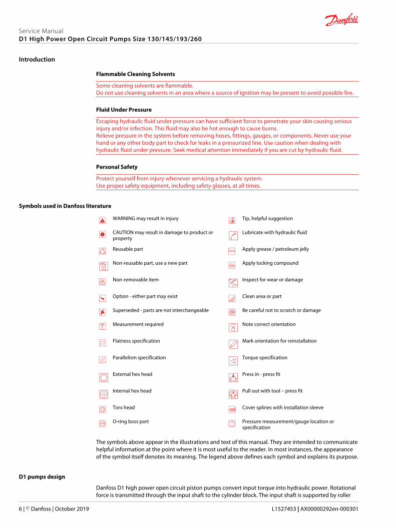
Symbols used in Danfoss literature
WARNING may result in injury Tip, helpful suggestion
CAUTION may result in damage to product orproperty
Lubricate with hydraulic fluid
Reusable part Apply grease / petroleum jelly
Non-reusable part, use a new part Apply locking compound
Non-removable item Inspect for wear or damage
Option - either part may exist Clean area or part
Superseded - parts are not interchangeable Be careful not to scratch or damage
Measurement required Note correct orientation
Flatness specification Mark orientation for reinstallation
Parallelism specification Torque specification
External hex head Press in - press fit
Internal hex head Pull out with tool – press fit
Torx head Cover splines with installation sleeve
O-ring boss port Pressure measurement/gauge location orspecification
The symbols above appear in the illustrations and text of this manual. They are intended to communicatehelpful information at the point where it is most useful to the reader. In most instances, the appearanceof the symbol itself denotes its meaning. The legend above defines each symbol and explains its purpose.
D1 pumps design
Danfoss D1 high power open circuit piston pumps convert input torque into hydraulic power. Rotationalforce is transmitted through the input shaft to the cylinder block. The input shaft is supported by roller
Service ManualD1 High Power Open Circuit Pumps Size 130/145/193/260
Introduction
6 | © Danfoss | October 2019 L1527453 | AX00000292en-000301
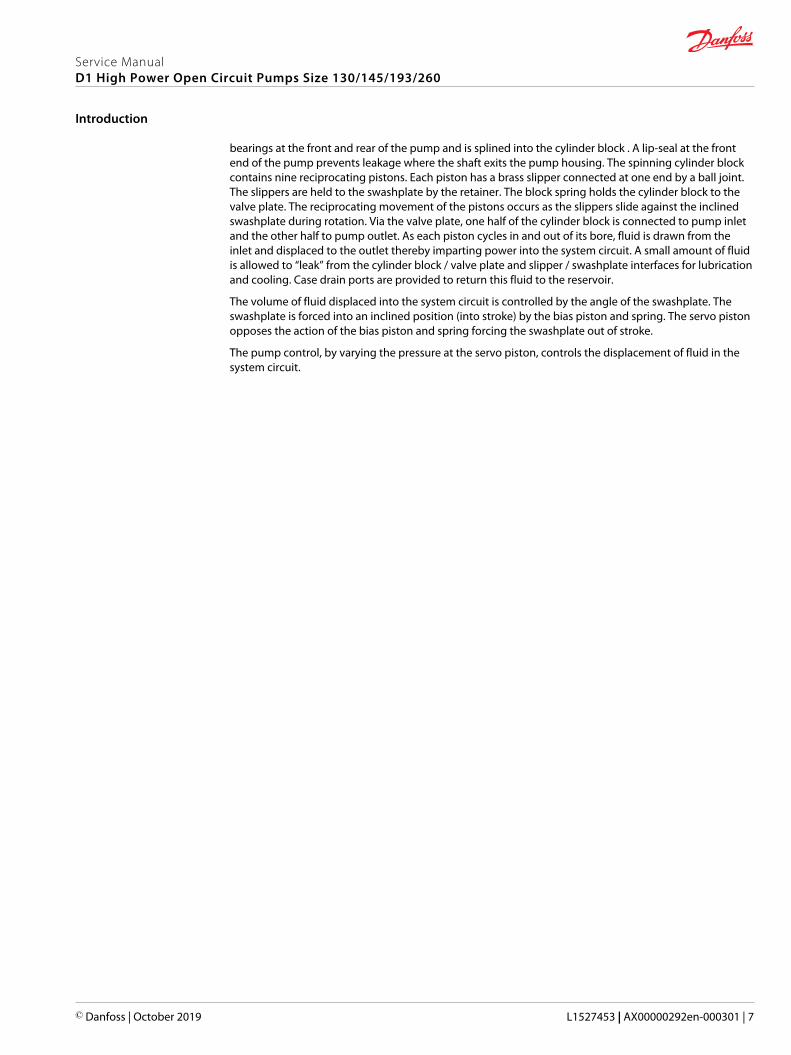
bearings at the front and rear of the pump and is splined into the cylinder block . A lip-seal at the frontend of the pump prevents leakage where the shaft exits the pump housing. The spinning cylinder blockcontains nine reciprocating pistons. Each piston has a brass slipper connected at one end by a ball joint.The slippers are held to the swashplate by the retainer. The block spring holds the cylinder block to thevalve plate. The reciprocating movement of the pistons occurs as the slippers slide against the inclinedswashplate during rotation. Via the valve plate, one half of the cylinder block is connected to pump inletand the other half to pump outlet. As each piston cycles in and out of its bore, fluid is drawn from theinlet and displaced to the outlet thereby imparting power into the system circuit. A small amount of fluidis allowed to “leak” from the cylinder block / valve plate and slipper / swashplate interfaces for lubricationand cooling. Case drain ports are provided to return this fluid to the reservoir.
The volume of fluid displaced into the system circuit is controlled by the angle of the swashplate. Theswashplate is forced into an inclined position (into stroke) by the bias piston and spring. The servo pistonopposes the action of the bias piston and spring forcing the swashplate out of stroke.
The pump control, by varying the pressure at the servo piston, controls the displacement of fluid in thesystem circuit.
Service ManualD1 High Power Open Circuit Pumps Size 130/145/193/260
Introduction
© Danfoss | October 2019 L1527453 | AX00000292en-000301 | 7

D1 pump cross-section view
D1 pump
1
2
3
4
56
7
8
9
1011
121314
15
16
1. Shaft seal2. Roller bearing3. Housing4. Minimum displacement limiter5. Bias piston6. Control7. Valve plate8. Endcap9. Charge pump
10. Servo piston11. Cylinder block12. Maximum displacement limiter13. Piston14. Swashplate15. Swashplate Bearing16. Input shaft
Some internal parts may be different depending on the pump size.
Service ManualD1 High Power Open Circuit Pumps Size 130/145/193/260
Introduction
8 | © Danfoss | October 2019 L1527453 | AX00000292en-000301
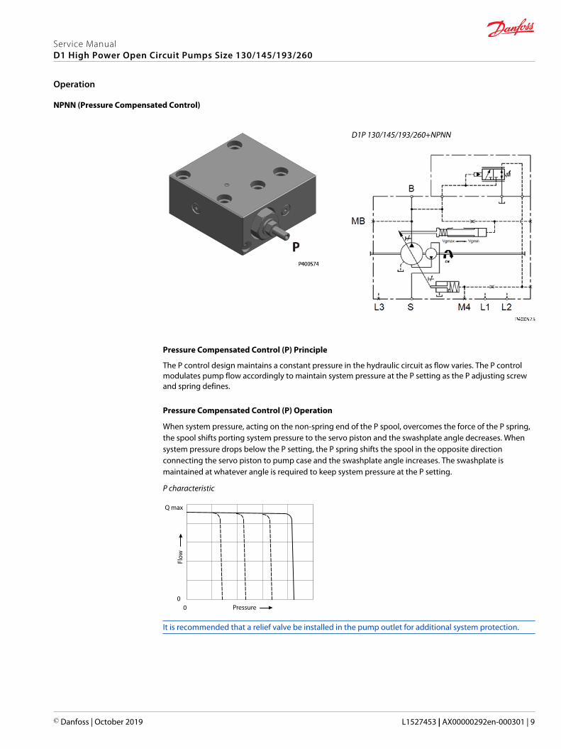
NPNN (Pressure Compensated Control)
D1P 130/145/193/260+NPNN
Pressure Compensated Control (P) Principle
The P control design maintains a constant pressure in the hydraulic circuit as flow varies. The P controlmodulates pump flow accordingly to maintain system pressure at the P setting as the P adjusting screwand spring defines.
Pressure Compensated Control (P) Operation
When system pressure, acting on the non-spring end of the P spool, overcomes the force of the P spring,the spool shifts porting system pressure to the servo piston and the swashplate angle decreases. Whensystem pressure drops below the P setting, the P spring shifts the spool in the opposite directionconnecting the servo piston to pump case and the swashplate angle increases. The swashplate ismaintained at whatever angle is required to keep system pressure at the P setting.
P characteristic
00
Q max
Flow
Pressure
It is recommended that a relief valve be installed in the pump outlet for additional system protection.
Service ManualD1 High Power Open Circuit Pumps Size 130/145/193/260
Operation
© Danfoss | October 2019 L1527453 | AX00000292en-000301 | 9
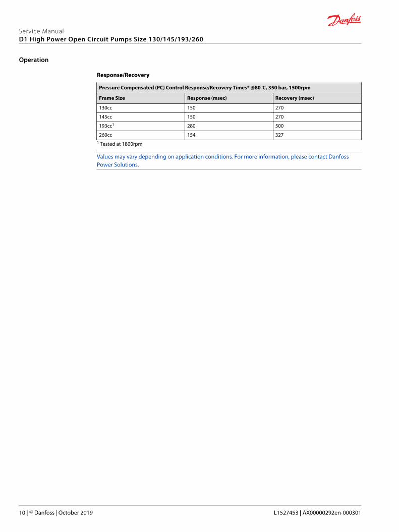
Response/Recovery
Pressure Compensated (PC) Control Response/Recovery Times* @80°C, 350 bar, 1500rpm
Frame Size Response (msec) Recovery (msec)
130cc 150 270
145cc 150 270
193cc1 280 500
260cc 154 3271 Tested at 1800rpm
Values may vary depending on application conditions. For more information, please contact DanfossPower Solutions.
Service ManualD1 High Power Open Circuit Pumps Size 130/145/193/260
Operation
10 | © Danfoss | October 2019 L1527453 | AX00000292en-000301

NPSN (Pressure Compensated Control + Load Sensing Control)
D1P 130/145/193/260+NPSN
Pressure Compensated Control (P) Principle and Operation
Please refer to NPNN (Pressure Compensated Control) on page 9
Load Sensing Control (S) Principle
The S control design matches pump flow with system demand. The S control senses the flow demand ofthe system as a pressure drop across the external control valve (1).
As (1) opens and closes, the pressure difference (delta) across the valve changes. When opening, the deltadecreases. When closing, the delta increases. The S control then increases or decreases pump flow to thesystem until the pressure delta becomes equal to the S setting as defined by the S adjusting screw andspring.
Load Sensing Control (S) Operation
Through internal porting, system pressure [upstream of (1)] is applied to the non-spring end of the Sspool, and through hydraulic line connected at port X, load pressure [downstream of (1)] is applied to thespring end. This arrangement allows the S spool to act on the delta between system pressure and loadpressure. The S spring sets the threshold of operation (S setting).
Because the swashplate is biased to maximum angle, the pump attempts to deliver full flow to thehydraulic system. When the flow being delivered exceeds demand, the pressure delta across the (1) isgreat enough to overcome spring force and shift the S spool porting system pressure to the servo piston.The pump de-strokes reducing flow until the delta across the (1) becomes equal to the S setting.
When flow being delivered is less than demand, the delta across the (1) drops below the S setting and theS spring shifts the spool connecting the servo piston to pump case. The pump strokes increasing flowuntil the delta across the (1) becomes equal to the S setting.
When the external control valve (1) is placed in neutral, it connects the LS signal line to drain. With no LSpressure acting on the non-spring end of the LS spool, the pump adjusts stroke to whatever positionnecessary to maintain system pressure at the LS setting. The pump is now in low pressure standby mode.
(1) is not in the scope of supply.
Service ManualD1 High Power Open Circuit Pumps Size 130/145/193/260
Operation
© Danfoss | October 2019 L1527453 | AX00000292en-000301 | 11

S characteristic
00
Q max
Flow
Pressure
P se
ttin
g
For additional system protection, install a relief valve in the pump outlet line.
NPSN Priority
The Pressure Compensated Control (P) has priority over the Load Sensing Control (S).
Response/Recovery
Load Sensing (LS) Response/Recovery Times @80°C, 1500rpm, LS Setting at 25 bar
Frame Size Response (msec) Recovery (msec)
130cc 260 360
145cc 260 360
193cc1 233 264
260cc 309 3271 Tested with a LS setting of 20bar
Values may vary depending on application conditions. For more information, please contact DanfossPower Solutions
Service ManualD1 High Power Open Circuit Pumps Size 130/145/193/260
Operation
12 | © Danfoss | October 2019 L1527453 | AX00000292en-000301

NPNR (Pressure Compensated Control + Remote Pressure Compensated Control)
D1P 130/145/193/260+NPNR
Pressure Compensated Control (P) Principle and Operation
Please refer to NPNN (Pressure Compensated Control) on page 9.
Remote Pressure Compensated Control (R) Principle
The remote PC control is a two-stage control that allows multiple PC settings. Remote PC controls arecommonly used in applications requiring low and high pressure PC operation.
For this control, Danfoss recommends a load sense setting of 20bar.
Remote Pressure Compensated Control (R) Operation
The remote PC control uses a pilot line connected to an external hydraulic valve. The external valvechanges pressure in the pilot line, causing the PC control to operate at a lower pressure. When the pilotline is vented to reservoir, the pump maintains pressure at the load sense setting. When pilot flow isblocked, the pump maintains pressure at the PC setting. An on-off solenoid valve can be used in the pilotline to create a low-pressure standby mode. A proportional solenoid valve, coupled with amicroprocessor control, can produce an infinite range of operating pressures between the low pressurestandby setting and the PC setting.
R characteristic
00
Q max
Flow
Pressure
RP s
ettin
g
PC s
ettin
g
For additional system protection, install a relief valve in the pump outlet line.
Service ManualD1 High Power Open Circuit Pumps Size 130/145/193/260
Operation
© Danfoss | October 2019 L1527453 | AX00000292en-000301 | 13
NPNR Priority
When the pump’s X-port is vented to tank, or limited to some pressure setting via a remote valve, theremote pressure compensator function will control the maximum outlet pressure of the pump. If thepump’s outlet pressure reaches the pressure setting of the pressure compensator (PC) function, the PCfunction will take priority and limit the pump’s maximum pressure.
Service ManualD1 High Power Open Circuit Pumps Size 130/145/193/260
Operation
14 | © Danfoss | October 2019 L1527453 | AX00000292en-000301
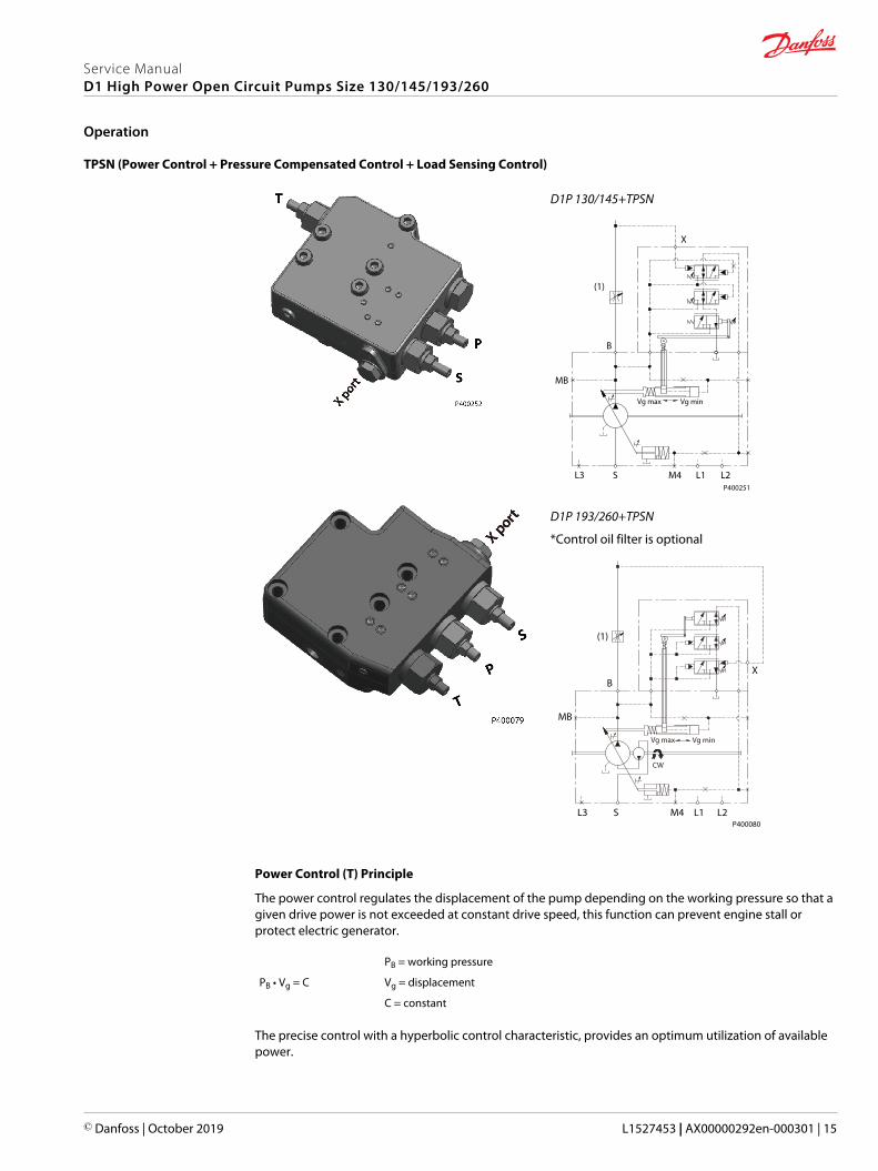
TPSN (Power Control + Pressure Compensated Control + Load Sensing Control)
D1P 130/145+TPSN
X
MB
B
(1)
P400251
Vg minVg max
L3 S M4 L1 L2
D1P 193/260+TPSN
*Control oil filter is optional
P400080
X
Vg min
CW
Vg max
MB
B
L3 S M4 L1 L2
(1)
Power Control (T) Principle
The power control regulates the displacement of the pump depending on the working pressure so that agiven drive power is not exceeded at constant drive speed, this function can prevent engine stall orprotect electric generator.
PB = working pressure
PB • Vg = C Vg = displacement
C = constant
The precise control with a hyperbolic control characteristic, provides an optimum utilization of availablepower.
Service ManualD1 High Power Open Circuit Pumps Size 130/145/193/260
Operation
© Danfoss | October 2019 L1527453 | AX00000292en-000301 | 15

Power Control (T) Operation
The working pressure acts on a rack-pivot via a roller jack which produces a rotating torque, an externallyadjustable spring force counteracts this which determines the power setting.
If the moment generated by working pressure exceeds the moment generated by spring force, thecontrol valve is actuated by the rack-pivot, and pump reduces displacement. The lever length at the rack-pivot is shortened and the working pressure can increase at the same rate as the displacement decreaseswithout the drive powers being exceeded.
(PB • Vg = C).
The hydraulic output power (characteristic T) is influenced by the efficiency of the pump.
T characteristic
Q max
00
Flow
Pressure
Pressure Compensated Control (P) Principle and Operation
Please refer to NPNN (Pressure Compensated Control) on page 9
Load Sensing Control (S) Principle and Operation
Please refer to NPSN (Pressure Compensated Control + Load Sensing Control) on page 11
TPSN Priority
The Pressure Compensated Control (P) has priority over the Power Control (T), Power Control has priorityover Load Sensing Control (S).
Service ManualD1 High Power Open Circuit Pumps Size 130/145/193/260
Operation
16 | © Danfoss | October 2019 L1527453 | AX00000292en-000301

NNES (Electric Displacement Control + Load Sensing Control)
W Warning
(1) Adjustment is not permissible
D1P 130/145/193/260 NNES
X
E B
Vgmax Vgmin
B
MB
S M4L3 L1 L2
Electric Displacement Control (E) Principle
The electric displacement control uses an electric proportional solenoid valve to vary the pump’sdisplacement from minimum displacement to maximum displacement or from maximum displacementto minimum displacement. The swashplate angle (pump displacement) is proportional to the electricalinput signal (control current).
Electric Displacement Control (E) Operation
This control is current driven, requiring a Pulse Width Modulated (PWM) signal. Pulse width modulationallows more precise control of current to the solenoid. The PWM signal causes the solenoid pin to pushagainst the E spool, which depressurizes the end of servo piston, the swashplate angle increases underthe force of the bias piston
A swashplate feedback link provides swashplate position force to the solenoid through the E spool’slinear spring. The control reaches equilibrium when the position of the swashplate spring feedback forceexactly balances the input command solenoid force from the operator. As working pressure changes withload, the control and servo/swashplate system work constantly to maintain the commanded position ofthe swashplate.
Electric Displacement Control (E) Operating Instruction
To make sure the electric displacement control works properly, a minimum control pressure of 30 bar[435 psi] is required. The required control pressure is taken either from the working pressure, or from theexternally applied control pressure at the E port.
If you can’t make sure that the working pressure is above 30 bar all the time, then a minimum of 30bar[435 psi] pressure supply at the E port is mandatory in order to control the displacement of the pump atall times. This pressure supply can be provided from different sources, such as an additional small gear orpiston pump and a relief valve, or an accumulator.
If E port is not connected, remove the shuttle valve
Service ManualD1 High Power Open Circuit Pumps Size 130/145/193/260
Operation
© Danfoss | October 2019 L1527453 | AX00000292en-000301 | 17
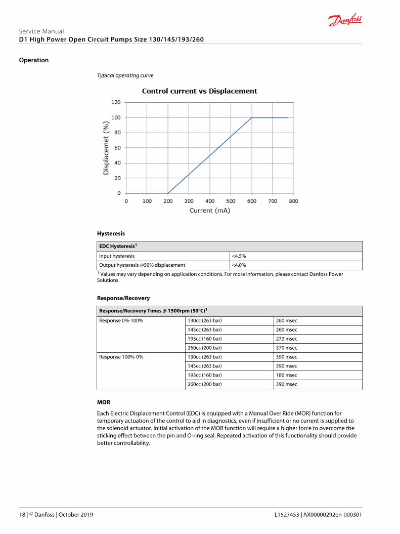
Typical operating curve
Hysteresis
EDC Hysteresis1
Input hysteresis <4.5%
Output hysteresis @50% displacement <4.0%1 Values may vary depending on application conditions. For more information, please contact Danfoss PowerSolutions
Response/Recovery
Response/Recovery Times @ 1500rpm (50°C)1
Response 0%-100% 130cc (263 bar) 260 msec
145cc (263 bar) 260 msec
193cc (160 bar) 272 msec
260cc (200 bar) 370 msec
Response 100%-0% 130cc (263 bar) 390 msec
145cc (263 bar) 390 msec
193cc (160 bar) 186 msec
260cc (200 bar) 390 msec
MOR
Each Electric Displacement Control (EDC) is equipped with a Manual Over Ride (MOR) function fortemporary actuation of the control to aid in diagnostics, even if insufficient or no current is supplied tothe solenoid actuator. Initial activation of the MOR function will require a higher force to overcome thesticking effect between the pin and O-ring seal. Repeated activation of this functionality should providebetter controllability.
Service ManualD1 High Power Open Circuit Pumps Size 130/145/193/260
Operation
18 | © Danfoss | October 2019 L1527453 | AX00000292en-000301
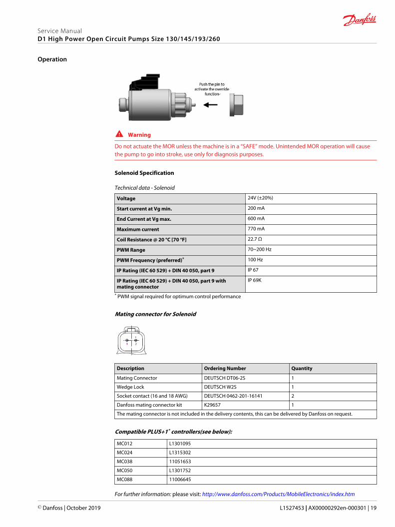
W Warning
Do not actuate the MOR unless the machine is in a “SAFE” mode. Unintended MOR operation will causethe pump to go into stroke, use only for diagnosis purposes.
Solenoid Specification
Technical data - Solenoid
Voltage 24V (±20%)
Start current at Vg min. 200 mA
End Current at Vg max. 600 mA
Maximum current 770 mA
Coil Resistance @ 20 °C [70 °F] 22.7 Ω
PWM Range 70~200 Hz
PWM Frequency (preferred)* 100 Hz
IP Rating (IEC 60 529) + DIN 40 050, part 9 IP 67
IP Rating (IEC 60 529) + DIN 40 050, part 9 withmating connector
IP 69K
* PWM signal required for optimum control performance
Mating connector for Solenoid
Description Ordering Number Quantity
Mating Connector DEUTSCH DT06-2S 1
Wedge Lock DEUTSCH W2S 1
Socket contact (16 and 18 AWG) DEUTSCH 0462-201-16141 2
Danfoss mating connector kit K29657 1
The mating connector is not included in the delivery contents, this can be delivered by Danfoss on request.
Compatible PLUS+1® controllers(see below):
MC012 L1301095
MC024 L1315302
MC038 11051653
MC050 L1301752
MC088 11006645
For further information: please visit: http://www.danfoss.com/Products/MobileElectronics/index.htm
Service ManualD1 High Power Open Circuit Pumps Size 130/145/193/260
Operation
© Danfoss | October 2019 L1527453 | AX00000292en-000301 | 19
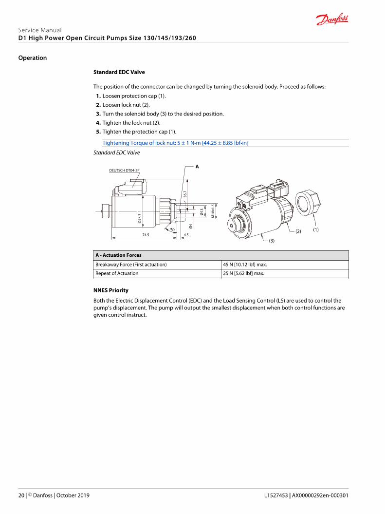
Standard EDC Valve
The position of the connector can be changed by turning the solenoid body. Proceed as follows:
1. Loosen protection cap (1).
2. Loosen lock nut (2).
3. Turn the solenoid body (3) to the desired position.
4. Tighten the lock nut (2).
5. Tighten the protection cap (1).
Tightening Torque of lock nut: 5 ± 1 N•m [44.25 ± 8.85 lbf•in]
Standard EDC Valve
DEUTSCH DT04-2P
74.5 4.5
(3)
A
(2) (1)45°
Ø37
.1
36.7
Ø4
Ø13
M18
x1.5
A - Actuation Forces
Breakaway Force (First actuation) 45 N [10.12 lbf] max.
Repeat of Actuation 25 N [5.62 lbf] max.
NNES Priority
Both the Electric Displacement Control (EDC) and the Load Sensing Control (LS) are used to control thepump’s displacement. The pump will output the smallest displacement when both control functions aregiven control instruct.
Service ManualD1 High Power Open Circuit Pumps Size 130/145/193/260
Operation
20 | © Danfoss | October 2019 L1527453 | AX00000292en-000301
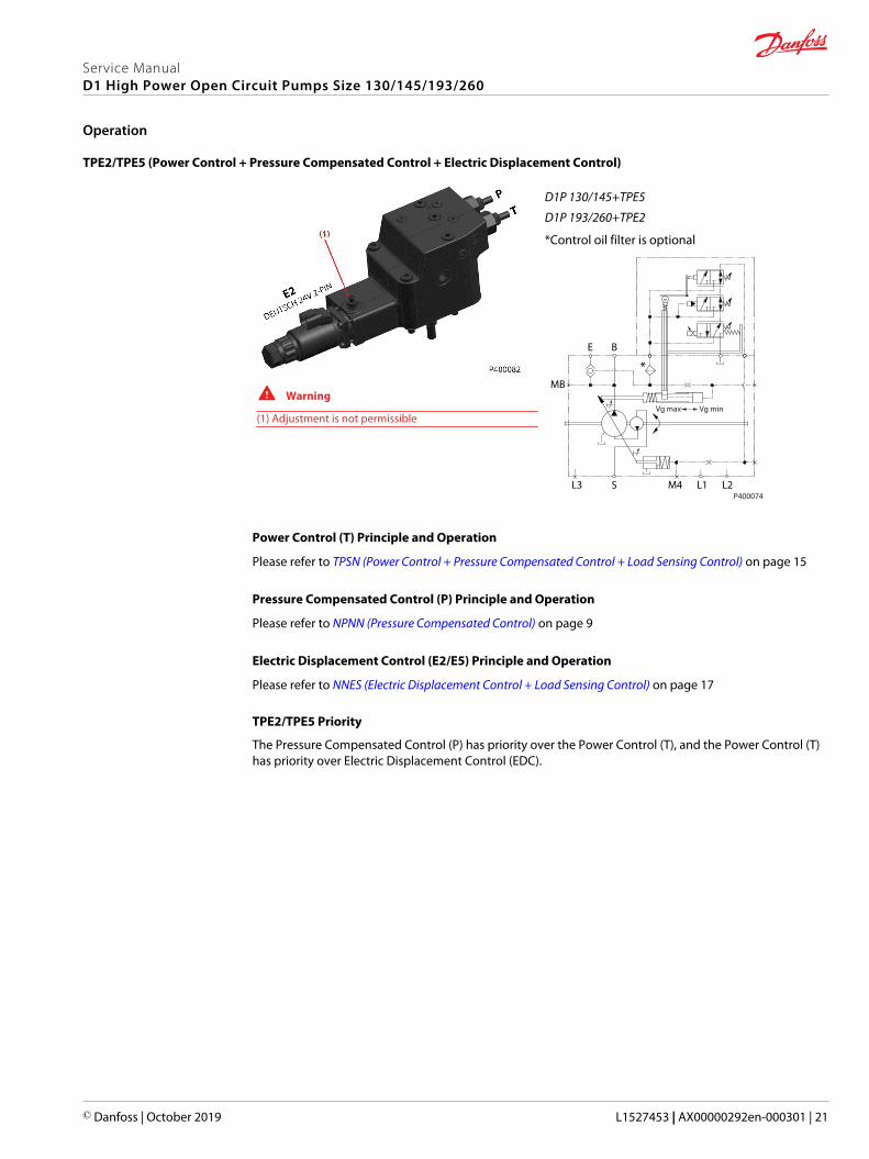
TPE2/TPE5 (Power Control + Pressure Compensated Control + Electric Displacement Control)
W Warning
(1) Adjustment is not permissible
D1P 130/145+TPE5
D1P 193/260+TPE2
*Control oil filter is optional
MB
E B
L3 S M4 L1 L2
Vg minVg max
P400074
*
Power Control (T) Principle and Operation
Please refer to TPSN (Power Control + Pressure Compensated Control + Load Sensing Control) on page 15
Pressure Compensated Control (P) Principle and Operation
Please refer to NPNN (Pressure Compensated Control) on page 9
Electric Displacement Control (E2/E5) Principle and Operation
Please refer to NNES (Electric Displacement Control + Load Sensing Control) on page 17
TPE2/TPE5 Priority
The Pressure Compensated Control (P) has priority over the Power Control (T), and the Power Control (T)has priority over Electric Displacement Control (EDC).
Service ManualD1 High Power Open Circuit Pumps Size 130/145/193/260
Operation
© Danfoss | October 2019 L1527453 | AX00000292en-000301 | 21

NPE2/NPE0 (Pressure Compensated Control + Electric Displacement Control)
D1P 260 with NPE2 (left); D1P 260 with NPE0 (right)
B
MB
S M4L3 L1 L2
Vgmax Vgmin
E
Vgmax Vgmin
B
MB
S M4L3 L1 L2
Pressure Compensated Control (P) Principle and Operation
Please refer to NPNN (Pressure Compensated Control) on page 9.
Electric Displacement Control (E2/E0) Principle and Operation
Please refer to NNES (Electric Displacement Control + Load Sensing Control) on page 17.
Shuttle Valve/Pilot Supply
Please refer to Electric Displacement Control (E) Operating Instruction section at NNES (ElectricDisplacement Control + Load Sensing Control) on page 17.
To determine if an external control pilot supply is needed, please consult your Danfoss Power Solutionsrepresentative.
D1P pumps configured with an NPE2 control will come with a shuttle valve installed at the E port. D1Ppumps with an NPE0 control will not include the shuttle valve.
Service ManualD1 High Power Open Circuit Pumps Size 130/145/193/260
Operation
22 | © Danfoss | October 2019 L1527453 | AX00000292en-000301

D1P pressure overview
Maximumworkingpressure
The highest recommended outlet (application). Operating at or below this pressureshould yield satisfactory product life. For all applications, the load should move belowthis pressure. This corresponds to the maximum allowable pressure compensatedcontrol setting.
Maximum(peak) pressure
The highest intermittent (t<1s) outlet pressure allowed. Maximum machine loadshould never exceed this pressure, and pressure overshoots should not exceed thispressure.
Inlet pressure The absolute pressure in the pump suction port, it is related to pump speed. Makesure it is in the allowable range, see D1 pump specifications.
Case pressure The case pressure at the ports L1 and L2 may be a maximum of 1.2 bar [17.4 psi]higher than the inlet pressure at the port S but not higher than 2 bar. Size drainplumbing accordingly and connect it to tank directly. The housing must always befilled with hydraulic fluid.
D1P speed overview
Ratedspeed
The fastest recommended operating speed at full displacement and at least 0.6 bar [8.7psi] abs with charge pump (0.8 bar [11.6 psi] abs without charge pump) inlet pressure.Operating at or below this speed should yield satisfactory product life.
Maximumspeed
The highest recommended operating speed at full power conditions. Operating at orbeyond maximum speed requires positive inlet pressure and/or a reduction of pumpoutlet flow. Refer to Inlet pressure vs. speed on page 23, chart below.
Inlet pressure vs. speed
0.80.9
Spee
d nm
ax/ n
max
1
0.9 1.0Displacement Vg/Vgmax
1.0
1.1
1.2
Pabs=1 bar [14.5 psi]
Pabs=1.5 bar [21.8 psi]
P400076
Minimumspeed
The lowest operating speed allowed. Operating below this speed will not yieldsatisfactory performance.
Caution! Threat to pump life!Working outside of the pump's operating parameters may result in shortened life expectancy of thepump.Always work within the operating conditions of the pump application.With accurate duty cycle information, your Danfoss Power Solutions representative can assist you incalculating expected pump life.
D1P fluid overview
Ratings and performance data for D1 pumps are based on operating with premium hydraulic fluidscontaining oxidation, rust, and foam inhibitors. These include premium turbine oils, API CD engine oils
Service ManualD1 High Power Open Circuit Pumps Size 130/145/193/260
Operating parameters
© Danfoss | October 2019 L1527453 | AX00000292en-000301 | 23

per SAE J183, M2C33F or G automatic transmission fluids (ATF), Dexron II (ATF) meeting Allison C-3 orCaterpillar T0‑2 requirements, and certain specialty agricultural tractor fluids. For more information onhydraulic fluid selection, see Danfoss Power Solutions publications 520L0463 Hydraulic Fluids andLubricants, Technical Information, and 520L0465 Experience with Biodegradable Hydraulic Fluids,Technical Information.
D1P viscosity
Minimum Viscosity This should only occur during brief occasions of maximum ambient temperatureand severe duty cycle operation.
MaximumViscosity
This should only occur at cold start. Pump performance will be reduced. Limitspeeds until the system warms up.
Maintain fluid viscosity within the recommended range for maximum efficiency and pump life.
D1P temperature overview
MinimumTemperature
Relates to the physical properties of the component materials. Cold oil will notaffect the durability of the pump components. However, it may affect the ability ofthe pump to provide flow and transmit power
MaximumTemperature
Relates to material properties. Don’t exceed it. Measure maximum temperature atthe hottest point in the system. This is usually the case drain.
D1P fluid velocity
Choose piping sizes and configurations sufficient to maintain optimum fluid velocity, and minimizepressure drops. This reduces noise, pressure drops, overheating and maximizes system life andperformance.
Recommended fluid velocities
System lines 6 to 9 m/sec
Suction line 1 to 2 m/sec
Case drain 3 to 5 m/sec
Typical guidelines; obey all pressure ratings.
Velocity equations
SI units
Q = flow (l/min)
A = area (mm²)
Velocity = (16.67•Q)/A (m/sec)
Service ManualD1 High Power Open Circuit Pumps Size 130/145/193/260
Operating parameters
24 | © Danfoss | October 2019 L1527453 | AX00000292en-000301
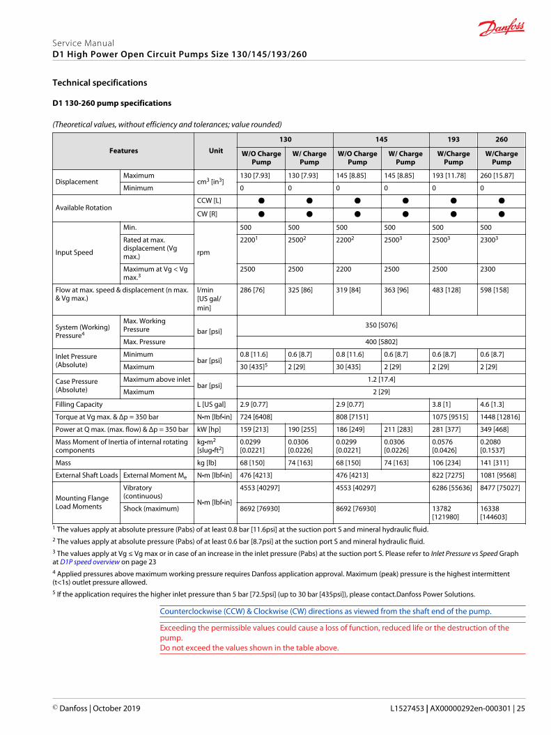
D1 130-260 pump specifications
(Theoretical values, without efficiency and tolerances; value rounded)
Features Unit130 145 193 260
W/O ChargePump
W/ ChargePump
W/O ChargePump
W/ ChargePump
W/ChargePump
W/ChargePump
DisplacementMaximum
cm3 [in3]130 [7.93] 130 [7.93] 145 [8.85] 145 [8.85] 193 [11.78] 260 [15.87]
Minimum 0 0 0 0 0 0
Available RotationCCW [L]
CW [R]
Input Speed
Min.
rpm
500 500 500 500 500 500
Rated at max.displacement (Vgmax.)
22001 25002 22002 25003 25003 23003
Maximum at Vg < Vgmax.3
2500 2500 2200 2500 2500 2300
Flow at max. speed & displacement (n max.& Vg max.)
l/min[US gal/min]
286 [76] 325 [86] 319 [84] 363 [96] 483 [128] 598 [158]
System (Working)Pressure4
Max. WorkingPressure bar [psi]
350 [5076]
Max. Pressure 400 [5802]
Inlet Pressure(Absolute)
Minimumbar [psi]
0.8 [11.6] 0.6 [8.7] 0.8 [11.6] 0.6 [8.7] 0.6 [8.7] 0.6 [8.7]
Maximum 30 [435]5 2 [29] 30 [435] 2 [29] 2 [29] 2 [29]
Case Pressure(Absolute)
Maximum above inletbar [psi]
1.2 [17.4]
Maximum 2 [29]
Filling Capacity L [US gal] 2.9 [0.77] 2.9 [0.77] 3.8 [1] 4.6 [1.3]
Torque at Vg max. & Δp = 350 bar N•m [lbf•in] 724 [6408] 808 [7151] 1075 [9515] 1448 [12816]
Power at Q max. (max. flow) & Δp = 350 bar kW [hp] 159 [213] 190 [255] 186 [249] 211 [283] 281 [377] 349 [468]
Mass Moment of Inertia of internal rotatingcomponents
kg•m2
[slug•ft2]0.0299[0.0221]
0.0306[0.0226]
0.0299[0.0221]
0.0306[0.0226]
0.0576[0.0426]
0.2080[0.1537]
Mass kg [lb] 68 [150] 74 [163] 68 [150] 74 [163] 106 [234] 141 [311]
External Shaft Loads External Moment Me N•m [lbf•in] 476 [4213] 476 [4213] 822 [7275] 1081 [9568]
Mounting FlangeLoad Moments
Vibratory(continuous)
N•m [lbf•in]
4553 [40297] 4553 [40297] 6286 [55636] 8477 [75027]
Shock (maximum) 8692 [76930] 8692 [76930] 13782[121980]
16338[144603]
1 The values apply at absolute pressure (Pabs) of at least 0.8 bar [11.6psi] at the suction port S and mineral hydraulic fluid.2 The values apply at absolute pressure (Pabs) of at least 0.6 bar [8.7psi] at the suction port S and mineral hydraulic fluid.3 The values apply at Vg ≤ Vg max or in case of an increase in the inlet pressure (Pabs) at the suction port S. Please refer to Inlet Pressure vs Speed Graphat D1P speed overview on page 234 Applied pressures above maximum working pressure requires Danfoss application approval. Maximum (peak) pressure is the highest intermittent(t<1s) outlet pressure allowed.5 If the application requires the higher inlet pressure than 5 bar [72.5psi] (up to 30 bar [435psi]), please contact.Danfoss Power Solutions.
Counterclockwise (CCW) & Clockwise (CW) directions as viewed from the shaft end of the pump.
Exceeding the permissible values could cause a loss of function, reduced life or the destruction of thepump.Do not exceed the values shown in the table above.
Service ManualD1 High Power Open Circuit Pumps Size 130/145/193/260
Technical specifications
© Danfoss | October 2019 L1527453 | AX00000292en-000301 | 25
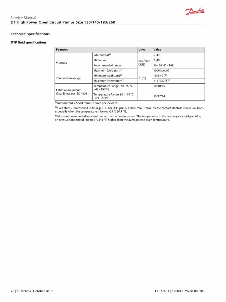
D1P fluid specifications
Features Units Value
Viscosity
Intermittent1)
mm2/sec[SUS]
5 [42]
Minimum 7 [49]
Recommended range 16 - 36 [81 - 168]
Maximum (cold start)2) 1600 [xxxxx]
Temperature rangeMinimum (cold start)2)
°C [°F]-40 [-40 °F]
Maximum intermittent1) 115 [239 °F]3)
Filtration (minimum)Cleanliness per ISO 4406
Temperature Range: -40 - 90 °C[-40 - 194°F]
20/18/15
Temperature Range: 90 - 115 °C[194 - 239°F] 19/17/14
1) Intermittent = Short term t < 3min per incident.2) Cold start = Short term t < 3min, p ≤ 30 bar [435 psi], n ≤ 1000 min-1(rpm) , please contact Danfoss Power Solutionsespecially when the temperature is below -25 °C [-13 °F].3) Must not be exceeded locally either (e.g. in the bearing area) . The temperature in the bearing area is (dependingon pressure and speed ) up to 5 °C [41 °F] higher than the average case drain temperature.
Service ManualD1 High Power Open Circuit Pumps Size 130/145/193/260
Technical specifications
26 | © Danfoss | October 2019 L1527453 | AX00000292en-000301
Recommendations of Fluid and Filter Maintenance
To ensure optimal product life, perform regular maintenance of the fluid and filter. Contaminated fluid isthe main cause of unit failure. Take care to maintain fluid cleanliness when servicing.
Check the reservoir daily for proper fluid level, the presence of water, and rancid fluid odor. Water in thefluid may be noted by a cloudy or milky appearance or free water in the bottom of the reservoir. Rancidodor indicates the fluid has been exposed to excessive heat. Change the fluid immediately if theseconditions occur. Correct the problem immediately.
Inspect vehicle for leaks daily.
Change the fluid and filter per the vehicle / machine manufacturer’s recommendations or at theseintervals: Change the fluid more frequently if it becomes contaminated with foreign matter (dirt, water,grease, etc.) or if the fluid is subjected to temperature levels greater that the recommended maximum.
Fluid and filter change interval
Reservoir type Maximum change interval
Sealed 2000 hours
Breather 500 hours
C Caution
High temperatures and pressures accelerate fluid aging. These conditions will require more frequent fluidchanges.
Change filters whenever the fluid is changed or when the filter indicator shows that it is necessary tochange the filter. Replace all fluid lost during filter change.
W Warning
Hydraulic fluid contains hazardous material. Avoid contact with hydraulic fluid. Always dispose of usedhydraulic fluid according to state, and federal environmental regulations. Never reuse hydraulic fluid.
Service ManualD1 High Power Open Circuit Pumps Size 130/145/193/260
Fluid and filter maintenance
© Danfoss | October 2019 L1527453 | AX00000292en-000301 | 27
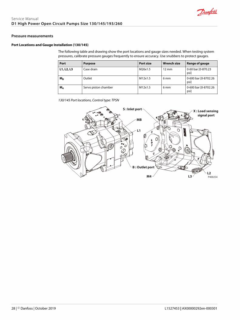
Port Locations and Gauge Installation (130/145)
The following table and drawing show the port locations and gauge sizes needed. When testing systempressures, calibrate pressure gauges frequently to ensure accuracy. Use snubbers to protect gauges.
Port Purpose Port size Wrench size Range of gauge
L1, L2, L3 Case drain M26x1.5 12 mm 0-60 bar [0-870.23psi]
MB Outlet M12x1.5 6 mm 0-600 bar [0-8702.26psi]
M4 Servo piston chamber M12x1.5 6 mm 0-600 bar [0-8702.26psi]
130/145 Port locations, Control type: TPSN
P400254
MB
L1
B : Outlet port
X : Load sensing signal port
S : Inlet port
M4 L3L2
Service ManualD1 High Power Open Circuit Pumps Size 130/145/193/260
Pressure measurements
28 | © Danfoss | October 2019 L1527453 | AX00000292en-000301

Port Locations and Gauge Instalation (193/260)
Port Purpose Port size Wrench size Range of gauge
L1, L2, L3 Case drain M33x2 17 mm 0-60 bar [0-870.23psi]
MB Outlet M12x1.5 6 mm 0-600 bar [0-870.23psi]
M4 Servo piston chamber M12x1.5 6 mm 0-600 bar [0-870.23psi]
193/260 Port location, Control type: TPE2
MBE : External Control Port
L1
S : Inlet Port
B : Outlet PortM4
L3
L2
193/260 Port location, Control type: TPSN
MB
L1
X : Load Sensing Signal Port
M4
L3L2
B : Outlet Port
S : Inlet Port
P400092
Service ManualD1 High Power Open Circuit Pumps Size 130/145/193/260
Pressure measurements
© Danfoss | October 2019 L1527453 | AX00000292en-000301 | 29

General
Follow this procedure when starting-up a new D1 installation or when restarting an installation in whichthe pump has been removed.
Prior to installing the pump, inspect for damage incurred during shipping. Make sure all systemcomponents (reservoir, hoses, valves, fittings, heat exchanger, etc.) are clean prior to filling with fluid.
Start-up Procedure
1. Connect the pump to the prime mover.
Ensure that the pump shaft is properly aligned with the shaft of the prime mover. Alignment shouldbe within 0.25 mm and the angle must not exceed 0.2°.
C Caution
Incorrect shaft alignment may result in damage to drive shaft, bearings, or seal which can causeexternal oil leakage.
2. Fill the reservoir with a recommended hydraulic fluid.
Always filter fluid through a 10 micron filter while pouring into the reservoir. Never reuse hydraulicfluid.
3. Fill the main pump housing with clean hydraulic fluid. Pour filtered oil directly into the upper mostcase drain port.
4. Fill the inlet line leading from the pump to the reservoir. Check the inlet line for properly tightenedfittings and be certain it is free of restrictions and air leaks.
5. To ensure the pump stays filled with oil, install the case drain line in the upper most case drain port.
6. Install a gauge at port MB to monitor system pressure during start up.
Follow recommendations in the vehicle / machine operator’s manual for prime mover start upprocedures.
7. Switch system to free circulation or to lowest pressure, jog the prime mover or run at the lowestpossible speed until pump and all pipes are filled and free from air bubbles. Raise pressure settingonly when all air is removed.
Let the pump work at reduced pressure for 5 - 10 min, check if all pipes and connections are leak-freeand tight.
8. Check the suction pressure at port S of the axial piston pump at nominal speed and maximum flow,make sure it is in allowable range.
9. Check the case drain pressure at the connected port L1 or L2 at maximum pressure, make sure it is inallowable range.
10. Shut down the prime mover and remove the pressure gauge. Replace plug at port MB.
11. Check the fluid level in the reservoir; add clean filtered fluid if necessary.
The pump is now ready for operation.
Service ManualD1 High Power Open Circuit Pumps Size 130/145/193/260
Initial start-up procedures
30 | © Danfoss | October 2019 L1527453 | AX00000292en-000301

Excessive Noise and /or Vibration
Item Description Action
Check fluid level in reservoir. Insufficient hydraulic fluid causescavitation.
Fill the reservoir to proper level.
Check for air in system. Air in system causes noisy, erraticcontrol.
Purge air and tighten fittings. Checkinlet for leaks.
Check pump inlet pressure / vacuum. Improper inlet conditions causeerratic behavior and low output flow.
Correct pump inlet pressure /vacuum conditions.
Inspect shaft couplings. A loose or incorrect shaft couplingcauses excessive noise and / orvibration.
Repair or replace coupling andensure that correct coupling is used.
Check shaft alignment. Misaligned shafts create excessivenoise and / or vibration.
Correct shaft misalignment.
Hydraulic fluid viscosity aboveacceptable limits.
Hydraulic fluid viscosity aboveacceptable limits or low fluidtemperature will not allow the pumpto fill or control to operate properly.
Allow system to warm up beforeoperating, or use fluid with theappropriate viscosity grade forexpected operating temperatures.
Low Pump Output Flow
Item Description Action
Check fluid level in reservoir. Insufficient hydraulic fluid will limitoutput flow and cause internaldamage to pump.
Fill the reservoir to proper level.
Hydraulic fluid viscosity aboveacceptable limits.
Fluid viscosity above acceptablelimits or low fluid temperature willnot allow the pump to fill or controlto operate properly.
Allow system to warm up beforeoperating, or use fluid with theappropriate viscosity grade forexpected operating temperatures.
Check external system relief valvesetting.
External relief valve set below PCsetting causes low output flow.
Adjust external relief valve followingmanufacturer’s recommendation.External relief valve setting must beabove PC setting to operate properly.
Check pressure compensate (PC),load sensing (LS) and power (T)control setting.
Low PC setting prevents the pumpfrom achieving full stroke. Low LSsetting limits output flow. Low Tsetting limits output flow.
Contact Danfoss Service.
Check LS control signal pressures. Incorrect LS signal will not allowpump to operate correctly.
Inspect system to ensure that properLS signal transmit to pump.
Check Pilot pressure for hydraulicsdisplacement control and inputcurrent for electric displacementcontrol.
Incorrect input signal causes lowoutput flow.
Adjust input hydraulic or electricsignal to right value.
Check pump inlet pressure / vacuum. High inlet vacuum causes low outputflow.
Correct inlet pressure conditions.
Check input speed. Low input speeds decrease flow. Adjust input speed.
Check pump rotation. Incorrect rotational configurationcauses low flow.
Use pump with appropriaterotational configuration.
No or Low System Pressure
Item Description Action
Check pressure compensate (PC) andpower (T) control setting.
Low PC and T setting leads to lowsystem pressure.
Contact Danfoss Service.
Check external relief valve. External relief valve setting below PCsetting.
Adjust external relief valve accordingto manufacturer’s recommendations.External relief valve must be setabove PC setting to operate properly.
Service ManualD1 High Power Open Circuit Pumps Size 130/145/193/260
Troubleshooting
© Danfoss | October 2019 L1527453 | AX00000292en-000301 | 31

Item Description Action
Check pilot pressure or controlpressure.
Insufficient pilot pressure or controlpressure.
Increase them to appropriate value.
Internal system leaks. Worn internal parts don’t allow thepump to operate properly.
Refer to Authorized Service Center forrequired repair.
Actuator Response is Sluggish
Item Description Action
Check external system relief valvesetting.
Low external relief valve setting slowsdown system.
Adjust external relief valve settingfollowing manufacturer’srecommendations. External reliefsetting must be above PC setting tooperate properly.
Check pressure compensate (PC),load sensing (LS) and power (T)control setting.
Low PC setting prevents the pumpfrom achieving full stroke. Low LSsetting limits output flow. Low Tsetting limits output Torque.
Contact Danfoss Service.
Check LS control signal pressures. Incorrect LS signal will not allowpump to operate correctly.
Inspect system to ensure that properLS signal transmit to pump.
Check Pilot pressure for hydraulicsdisplacement control and inputcurrent for electric displacementcontrol.
Incorrect input signal causes lowoutput flow.
Adjust input hydraulic or electricsignal to right value.
Internal system leaks. Worn internal parts don’t allow thepump to operate properly.
Refer to Authorized Service Center forrequired repair.
Hydraulic fluid viscosity aboveacceptable limits.
Hydraulic fluid viscosity aboveacceptable limits or low fluidtemperature will not allow the pumpto fill or control to operate properly.
Allow system to warm up beforeoperation or sue fluid with theappropriate viscosity grade forexpected operating temperatures.
Check external system valving. Malfunctioning valving may not allowsystem to respond properly.
Repair or replace system valving asrequired.
Check pump case pressure. High case pressure causes the systemto be sluggish.
Correct case drain line restrictions.
Check pump inlet pressure / vacuum. High inlet vacuum causes low outputflow.
Correct inlet pressure conditions.
Pressure or Flow Instability
Item Description Action
Check for air in system. Air in system causes erratic operation. Activate PC allowing system to bleedair. Check inlet line for leaks andeliminate source of air ingression.
Check LS setting. Low LS setting may cause instability. Contact Danfoss Service.
Check LS signal line. Blocked LS signal line interferes withproper LS operation.
Remove blockage.
Check external relief valve and PCsetting.
Insufficient pressure differentialbetween PC setting and externalrelief valve.
Adjust external relief valve or PCcontrol settings to appropriate level.Relief valve setting must be above PCsetting to operate properly.
Check external relief valve. Chattering external relief valve maycause unstable feedback to pumpcontrol.
Adjust or replace relief valve.
Service ManualD1 High Power Open Circuit Pumps Size 130/145/193/260
Troubleshooting
32 | © Danfoss | October 2019 L1527453 | AX00000292en-000301

System Operating Hot
Item Descriptin Action
Check fluid level in reservoir. Insufficient volume of hydraulic fluidwill not meet cooling demands ofsystem.
Fill reservoir to proper level. Verifyproper size of reservoir.
Inspect heat exchanger. Check airflow and input air temperature forthe heat exchanger.
Insufficient air flow, high input airtemperature, or undersized heatexchanges will not meet coolingdemands of the system.
Clean, repair, or replace heatexchanger as required. Verify propersize of heat exchanger.
Check external system relief valvesetting.
Fluid passing through relief valveadds heat to system.
Adjust external system relief valvesetting following manufacturer’srecommendations. External reliefvalve setting must be above PCsetting for proper operation.
Check pump inlet pressure / vacuum. High inlet vacuum adds heat tosystem.
Correct inlet pressure / vacuumconditions.
High Inlet Vacuum
Item Description Action
Check fluid temperature. Low temperature increases viscosity.High fluid viscosity causes high inletvacuum.
Allow system to warm up beforeoperating.
Inspect inlet screen. Blocked or restricted inlet screencauses high inlet vacuum.
Clean screen / remove blockage.
Check inlet piping. Too many fittings, bends, or longpiping causes high inlet vacuum.
Eliminate fittings to make path moredirect.
Hydraulic fluid viscosity aboveacceptable limits.
High fluid viscosity causes high inletvacuum.
Select fluid with appropriate viscosityfor expected operating temperature.
C Caution
High inlet vacuum causes cavitation which can damage internal pump components.
Service ManualD1 High Power Open Circuit Pumps Size 130/145/193/260
Troubleshooting
© Danfoss | October 2019 L1527453 | AX00000292en-000301 | 33
Calculate Power Control Start Point Pressure and Corresponding Flow in Advance
If Power/Torque control is used:
1. Calculate the power control start point pressure according to the formula:
Power = P • n • Vg • 10-3
600 • η
P Power control start point pressure [bar]
n Pump input speed [rpm]
Vg Pump theoretical displacement [cc]
η Total efficiency, set at 91.2%
The start point pressure is the point in the Pressure vs Flow performance curve in which the Torquecontrol becomes active. The PC setting must be higher than this value, otherwise the PC function willtake priority before the MTC function becomes active. If the desired power setting is 90kW, the pumpinput speed is 1500 rpm and the pump’s theoretical displacement is 193cc, then solve for start pointPressure:
90 = P • 1500 • 193 • 10-3
600 • (.912)
Start point Pressure is calculated to be 170bar.
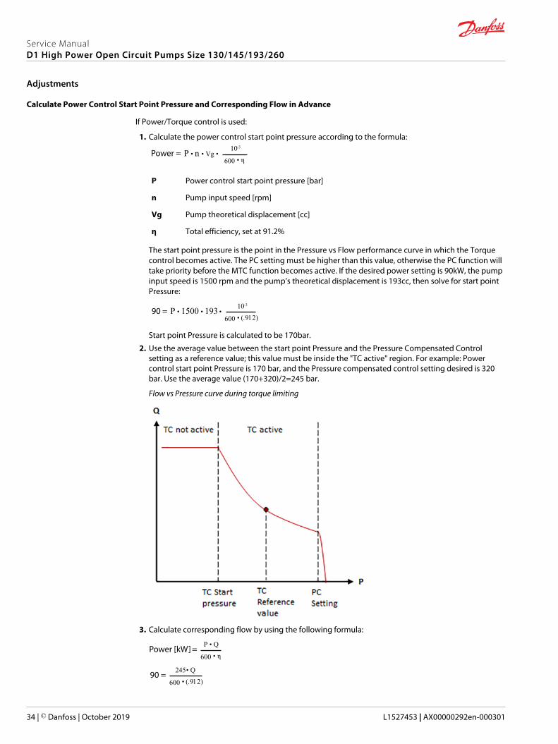
2. Use the average value between the start point Pressure and the Pressure Compensated Controlsetting as a reference value; this value must be inside the "TC active" region. For example: Powercontrol start point Pressure is 170 bar, and the Pressure compensated control setting desired is 320bar. Use the average value (170+320)/2=245 bar.
Flow vs Pressure curve during torque limiting
3. Calculate corresponding flow by using the following formula:
Power [kW] = P • Q
600 • η
90 = 245 • Q
600 • (.912)
Service ManualD1 High Power Open Circuit Pumps Size 130/145/193/260
Adjustments
34 | © Danfoss | October 2019 L1527453 | AX00000292en-000301

Q=201 l/min
Adjustments
Control 130/145 193 260
NPNN PC [bar per turn] 163.2 163.2 163.2
NPSN & NPNR PC [bar per turn] 163.2 163.2 163.2
LS [bar per turn] 26.4 26.4 26.4
TPSN PC [bar per turn] 271 163.2 163.2
LS [bar per turn] 50 26.4 26.4
MTC [kW perturn]@1500rpm
39 73.5 99
NNES LS [bar per turn] 26.4 26.4 26.4
EDC [mA offset perturn]
263 263 263
TPE5 PC [bar per turn] 163.2 N/A N/A
MTC [kW perturn]@1500rpm
50.8 N/A N/A
EDC [mA offset perturn]
263 N/A N/A
TPE2 PC [bar per turn] N/A 163.2 163.2
MTC [kW perturn]@1500rpm
N/A 73.5 99
EDC [mA offset perturn]
N/A 263 263
Electric Displacement Control Adjustment
1. Install a pressure gauge in port MB to measure outlet pressure. Install a flow meter in outlet line tomeasure pump flow.
W Warning
Escaping hydraulic fluid under pressure can have sufficient force to penetrate your skin causingserious injury and/or infection. Relieve pressure in the system before removing hoses, fittings,gauges, or components.Unintended movement of the machine or mechanism may cause injury to the technician orbystanders. To protect against unintended movement, secure the machine or disable / disconnectthe mechanism while servicing.
C Caution
Contamination can damage internal components and void the manufacturer’s warranty. Takeprecautions to ensure system cleanliness when removing and reinstalling system lines.
2. Locate the Electric Displacement Control Adjustment screw (see below).
The reference starting length, A, of the screw must be approximately 5-6mm. Adjusting this screw willoffset the Displacement vs Current curve and change the start current. The reference length is usefulin minimizing adjustment time (see the Adjustments table above for gain per turn information).
Service ManualD1 High Power Open Circuit Pumps Size 130/145/193/260
Adjustments
© Danfoss | October 2019 L1527453 | AX00000292en-000301 | 35

Reference starting screw length for EDC adjustment
A
3. Start the prime mover and input 700 mA to electric displacement control solenoid valve, then allowfluid to reach normal operating temperature. The pump must be at full displacement at this point.
If the pump does not provide flow with maximum current in the solenoid, the EDC adjustment screwmight need to be re-adjusted.a) Back out the screw to the reference length mentioned in the previous step and adjust carefully to
ensure proper function. Danfoss recommends a prime mover speed of 1500rpm for testing (unlessspecified otherwise).
The testing setup must be plumbed in a way so the EDC function works properly. Please refer to Electric Displacement Control (E) Operating Instruction.
4. Totally lock the LS control (if used) to avoid interference with EDC adjustment.a) Loosen the LS control lock nut and turn the LS control adjusting screw clockwise all the way to the
end, while holding the LS control adjusting screw.b) Torque the control lock nut to 21.6~24.6 N•m [191-218 lbf•in].
5. Load the pump's outlet pressure to 50 bar and input 400mA to electric displacement control, thenloosen the electric displacement control lock nut and turn its adjusting screw until the pumpdisplacement achieves (see Displacement table below), which can calculated by monitoring pumpoutlet flow and pump speed.
Clockwise turning the adjustment screw decreases pump displacement, counterclockwise turningincreases pump displacement. The displacement - current curve will offset (see Adjustments table) perturn.
The EDC adjustment screw is only sensitive in a limited area around the starting reference length ofthe set screw.
6. While holding the position of the electric displacement control adjusting screw, torque the lock nutto 9.5 N•m [84 lbf•in].
7. Test another current value.a) Input 500 mA to electric displacement control.b) Check if the displacement is within the range specified in the below table at this moment.
If the displacement is within the proper range, the electric displacement control adjustmentcomplete. If it is not, please re-adjust.
8. Stop the prime mover, remove the pressure gauge and flow meter, and return the system to itsnormal operating configuration.
Displacement
Input Current Size 130 Size 145 Size 193 Size 260
400mA+/-8 mA 67.5cc+/-5cc 67.5cc+/-5cc 92.5 cc+/-5cc 140.5 cc+/-5cc
500mA+/-8 mA 101cc+/-5cc 101cc+/-5cc 115.5 cc+/-5cc 172.5 cc+/-5cc
Service ManualD1 High Power Open Circuit Pumps Size 130/145/193/260
Adjustments
36 | © Danfoss | October 2019 L1527453 | AX00000292en-000301

Pressure Compensated Control Adjustment
1. Install a pressure gauge in port MB to measure outlet pressure.
2. Ensure the pump is operating at maximum displacement. If the control has Electric DisplacementControl, input 700mA to obtain maximum displacement.
3. Load the pump outlet pressure to at least 30 bar higher than the expected pressure compensatedcontrol setting. This may be achieved by operating a hydraulic function to its full extension, puttingthe pump in a dead-head condition.
4. Loosen the Pressure compensated control lock nut and turn the Pressure compensated controladjusting screw until the desired setting is indicated on the pressure gauge at port MB. Clockwiserotation increases pressure, counterclockwise rotation decreases; approximate gain per turn (see Adjustments table). Once the PC adjustment is complete, hold the position of the adjustment screwand torque the PC control lock nut to 21.6-24.6 N·m [lbf·in].
5. Stop the prime mover, remove the pressure gauge, and return the system to its normal operatingconfiguration.
If the pressure does not increase, an external system relief valve may require adjustment. Externalsystem relief valve must be set above the Pressure compensated control setting for proper operation.
Power Control Adjustment
1. Install a pressure gauge in port MB to measure outlet pressure. Install a flow meter in outlet line tomeasure pump flow.
2. Start the prime mover and make sure the pump is operating at maximum displacement. If the controlhas Electric Displacement Control, input 700mA to obtain maximum displacement. By doing this, thefunctions will not interfere with each other, if maximum displacement is commanded by the EDC atall times, the MTC function will take priority once the start point pressure is reached.
3. Load the pump outlet pressure to the reference pressure value previously obtained in the calculation,loosen the power control lock nut and turn the power control adjusting screw and monitor the flowmeter, when the flow meter shows the flow corresponding to the previous calculation, stop turning,while holding the position of power control adjusting screw, torque the power control lock nut to21.6~24.6 N•m [191-218 lbf•in]. Clockwise rotation increases power, counterclockwise rotationdecreases, approximate gain per turn (See Adjustments table.)
4. Stop the prime mover, remove the pressure gauge and flow meter, and return the system to itsnormal operating configuration.
Load Sensing Control Adjustment
1. Install a pressure gauge in port MB to measure outlet pressure, Tee-in a pressure gauge to the LSsignal line (port X) to measure LS signal pressure. Install a flow meter in outlet line to measure pumpflow.
2. Start Prime mover and allow fluid to reach normal operating temperature.
3. Totally lock the LS control; to do this first loosen the LS control lock nut and turn the LS controladjusting screw clockwise all the way to the end, while holding the LS control adjusting screw, torquethe control lock nut to 21.6~24.6 N•m [191-218 lbf•in].
4. Adjust Power control and pressure compensated control (if used).
Service ManualD1 High Power Open Circuit Pumps Size 130/145/193/260
Adjustments
© Danfoss | October 2019 L1527453 | AX00000292en-000301 | 37
5. After Step 4, slowly operate a hydraulic function that will demand approximately half flow from thepump, but keep outlet pressure below the power control pressure starting point (if Power control isused). Danfoss recommends loading the outlet pressure to 50bar.
W Warning
Escaping hydraulic fluid under pressure can have sufficient force to penetrate your skin causingserious injury and/or infection. Relieve pressure in the system before removing hoses, fittings,gauges, or components.Unintended movement of the machine or mechanism may cause injury to the technician orbystanders. To protect against unintended movement, secure the machine or disable / disconnectthe mechanism while servicing.
C Caution
Contamination can damage internal components and void the manufacturer’s warranty. Takeprecautions to ensure system cleanliness when removing and reinstalling system lines.
6. Loosen the LS control lock nut. While watching the pressure gauges, turn the LS control adjustingscrew counterclockwise until the desired pressure differential between port MB and port X isachieved (LS setting). Clockwise rotation increases the setting, counterclockwise rotation willdecrease it; approximate gain (see Table 1) per turn. While holding the position of the LS adjustingscrew, torque the LS lock nut to 21.6~24.6 N•m [191-218 lbf•in].
7. Stop the prime mover, remove the pressure gauge and flow meter, and return the system to itsnormal operating configuration.
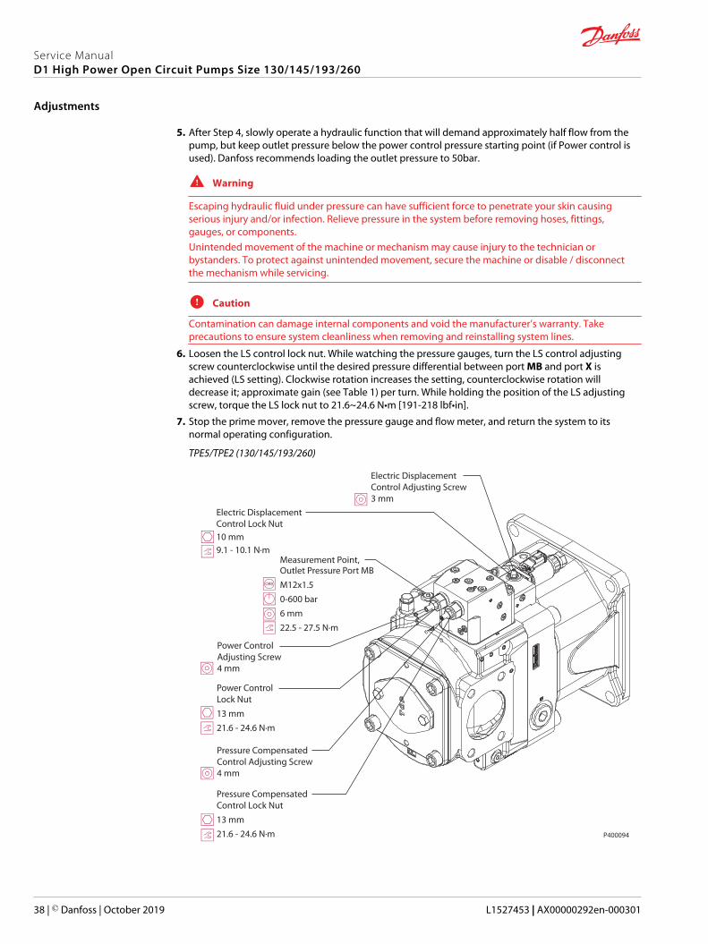
TPE5/TPE2 (130/145/193/260)
Measurement Point, Outlet Pressure Port MBM12x1.50-600 bar6 mm22.5 - 27.5 N·m
Power Control Adjusting Screw4 mm
Pressure Compensated Control Adjusting Screw4 mm
Power Control Lock Nut13 mm21.6 - 24.6 N·m
Pressure Compensated Control Lock Nut13 mm21.6 - 24.6 N·m
Electric DisplacementControl Adjusting Screw3 mm
Electric DisplacementControl Lock Nut10 mm9.1 - 10.1 N·m
P400094
Service ManualD1 High Power Open Circuit Pumps Size 130/145/193/260
Adjustments
38 | © Danfoss | October 2019 L1527453 | AX00000292en-000301
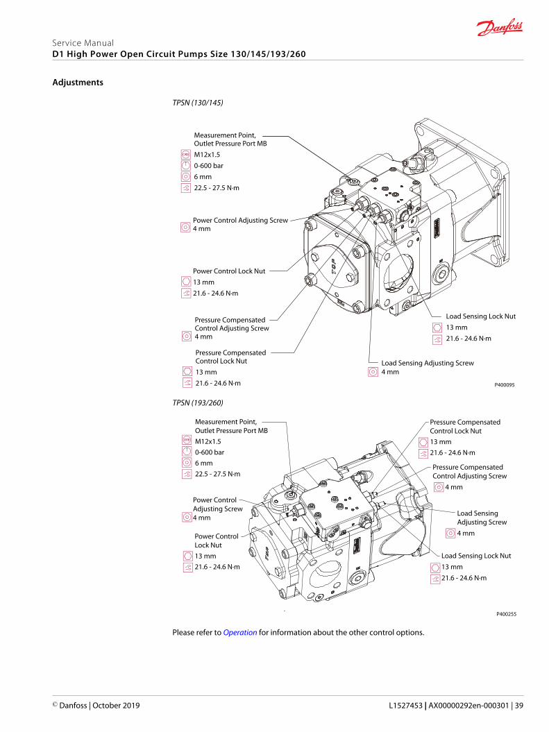
TPSN (130/145)
Measurement Point, Outlet Pressure Port MBM12x1.50-600 bar6 mm22.5 - 27.5 N·m
Power Control Adjusting Screw4 mm
Load Sensing Adjusting Screw4 mm
Pressure Compensated Control Adjusting Screw4 mm
Power Control Lock Nut13 mm21.6 - 24.6 N·m
Pressure Compensated Control Lock Nut13 mm21.6 - 24.6 N·m
Load Sensing Lock Nut13 mm21.6 - 24.6 N·m
P400095
TPSN (193/260)
P400255
Measurement Point, Outlet Pressure Port MBM12x1.50-600 bar6 mm22.5 - 27.5 N·m
Power Control Adjusting Screw4 mm
Power Control Lock Nut13 mm21.6 - 24.6 N·m
Pressure Compensated Control Lock Nut13 mm21.6 - 24.6 N·m
Pressure Compensated Control Adjusting Screw 4 mm
Load Sensing Adjusting Screw4 mm
Load Sensing Lock Nut13 mm21.6 - 24.6 N·m
Please refer to Operation for information about the other control options.
Service ManualD1 High Power Open Circuit Pumps Size 130/145/193/260
Adjustments
© Danfoss | October 2019 L1527453 | AX00000292en-000301 | 39
Displacement Limiters Adjustment
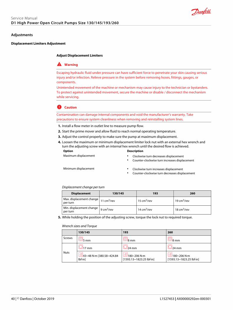
Adjust Displacement Limiters
W Warning
Escaping hydraulic fluid under pressure can have sufficient force to penetrate your skin causing seriousinjury and/or infection. Relieve pressure in the system before removing hoses, fittings, gauges, orcomponents.
Unintended movement of the machine or mechanism may cause injury to the technician or bystanders.To protect against unintended movement, secure the machine or disable / disconnect the mechanismwhile servicing.
C Caution
Contamination can damage internal components and void the manufacturer’s warranty. Takeprecautions to ensure system cleanliness when removing and reinstalling system lines.
1. Install a flow meter in outlet line to measure pump flow.
2. Start the prime mover and allow fluid to reach normal operating temperature.
3. Adjust the control properly to make sure the pump at maximum displacement.
4. Loosen the maximum or minimum displacement limiter lock nut with an external hex wrench andturn the adjusting screw with an internal hex wrench until the desired flow is achieved.Option DescriptionMaximum displacement • Clockwise turn decreases displacement
• Counter-clockwise turn increases displacement
Minimum displacement • Clockwise turn increases displacement• Counter-clockwise turn decreases displacement
Displacement change per turn
Displacement 130/145 193 260
Max. displacement changeper turn 11 cm3/rev 15 cm3/rev 19 cm3/rev
Min. displacement changeper turn 9 cm3/rev 14 cm3/rev 18 cm3/rev
5. While holding the position of the adjusting screw, torque the lock nut to required torque.
Wrench sizes and Torque
130/145 193 260
Screws5 mm 8 mm 8 mm
Nuts17 mm 24 mm 24 mm
43~48 N·m [380.58~424.84lbf·in]
180~206 N·m[1593.13~1823.25 lbf·in]
180~206 N·m[1593.13~1823.25 lbf·in]
Service ManualD1 High Power Open Circuit Pumps Size 130/145/193/260
Adjustments
40 | © Danfoss | October 2019 L1527453 | AX00000292en-000301
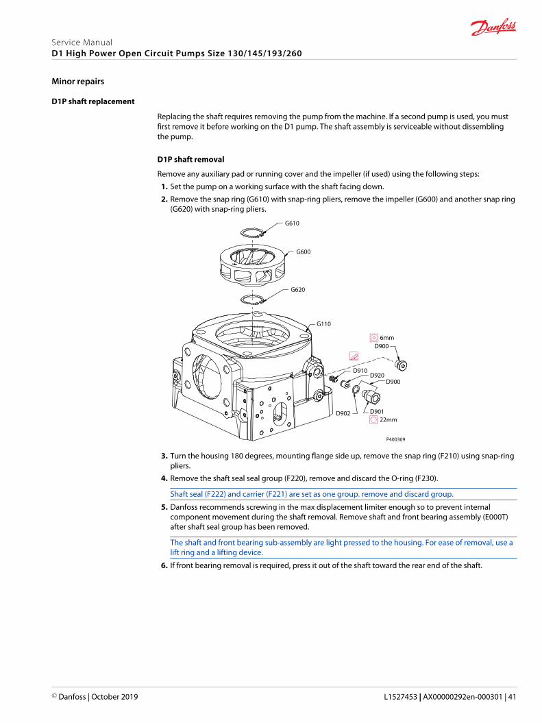
D1P shaft replacement
Replacing the shaft requires removing the pump from the machine. If a second pump is used, you mustfirst remove it before working on the D1 pump. The shaft assembly is serviceable without dissemblingthe pump.
D1P shaft removal
Remove any auxiliary pad or running cover and the impeller (if used) using the following steps:
1. Set the pump on a working surface with the shaft facing down.
2. Remove the snap ring (G610) with snap-ring pliers, remove the impeller (G600) and another snap ring(G620) with snap-ring pliers.
P400369
D901D902
D900
D900
D920D910
G110
G620
G600
G610
22mm
6mm
3. Turn the housing 180 degrees, mounting flange side up, remove the snap ring (F210) using snap-ringpliers.
4. Remove the shaft seal seal group (F220), remove and discard the O-ring (F230).
Shaft seal (F222) and carrier (F221) are set as one group. remove and discard group.
5. Danfoss recommends screwing in the max displacement limiter enough so to prevent internalcomponent movement during the shaft removal. Remove shaft and front bearing assembly (E000T)after shaft seal group has been removed.
The shaft and front bearing sub-assembly are light pressed to the housing. For ease of removal, use alift ring and a lifting device.
6. If front bearing removal is required, press it out of the shaft toward the rear end of the shaft.
Service ManualD1 High Power Open Circuit Pumps Size 130/145/193/260
Minor repairs
© Danfoss | October 2019 L1527453 | AX00000292en-000301 | 41

D1P shaft installation
1. Before reinstalling the shaft, press the shaft bearing onto shaft (if bearing was removed), usingexternal snap ring pliers to install retainer ring (not shown, see Repair Instructions manual) in shaft.
C Caution
The washer from the bearing must be on the shaft shoulder side and the retainer ring must be facingthe bearing with the small corner side.
2. With the pump’s mounting flange side up, coat bearing hole with hydraulic fluid, install shaft andfront bearing group to housing, knocking the bearing cup side lightly with a copper hammer if thereis considerable resistance until the shaft and bearing assembly is properly set in place.
C Caution
Do not hit the shaft, using a protective sleeve is recommended. Be careful with contaminants duringthe process.
3. Coat with assembly grease to hold the O-ring (F230) in bearing hole.
C Caution
Be careful when touching shaft splines; The retainer ring must be facing the bearing with small cornerside.
4. Lubricate the lip of the shaft seal (F222) with clean hydraulic grease. Install the carrier and sealassembly (F220) and make sure it is set properly by applying uniform force around the carrier. Oncethe seal carrier is properly set, use internal snap ring pliers to install retainer ring (F210) in housing.
5. If the pump has an impeller, reinstall it after the shaft installation is complete.
P400617
F210
F220
F221
F222
F230
E000T
Service ManualD1 High Power Open Circuit Pumps Size 130/145/193/260
Minor repairs
42 | © Danfoss | October 2019 L1527453 | AX00000292en-000301

Shaft Seal Replacement
D1 pump uses a lip-type shaft seal. You can replace this seal without major disassembly of the unit.Replacing the shaft seal requires removing the pump from the machine.
Removal
1. Using the appropriate snap-ring pliers, remove the retaining ring (F210) from the housing.
2. Remove the shaft seal and its carrier (F220) with appropriate tool (such as a flat-head screwdriver)from the bore in the pump housing and discard.
3. Remove the O-ring (F230) and discard.
Installation
1. Inspect the pump housing and new seals for damage. Inspect the sealing area on the shaft for rust,wear, or contamination. Polish the sealing area on the shaft if necessary.
2. Lubricate new O-ring (F230) with petroleum jelly and fit in the housing groove.
3. Lubricate the lip of the new shaft seal with clean hydraulic fluid. Place a protective sleeve over theshaft end to prevent damage to the seal during installation.
4. Keeping the new seal and its carrier perpendicular to the shaft, press them into the housing just farenough to clear the retaining ring groove. Install seal with the cupped side toward the shaft bearing.Do not damage the seal during installation.
5. Using the appropriate snap ring pliers, install the seal retaining ring.
6. Remove the installation sleeve.
F230
F220
F210P400096
Service ManualD1 High Power Open Circuit Pumps Size 130/145/193/260
Minor repairs
© Danfoss | October 2019 L1527453 | AX00000292en-000301 | 43
Auxiliary Flange and Charge Pump Replacement
Follow these steps to either remove, replace, or exchange auxiliary mounting pads and charge pump(impeller).
D1P auxiliary flange removal
1. Remove the screws (H140), retaining the cover plate (H150). Remove the seal (H130).
2. Remove the drive coupling (H200) if present.
3. Remove the 4 screws (H120), retaining the pad adapter (H100) to the end cap. Discard the padadapter O-ring (H110).
4. Use the appropriate snap-ring pliers, remove the retaining ring (G610) from the shaft.
5. Pull out the charge pump, discard it if it is damaged.
D1P auxiliary flange installation
1. Push in the new charge pump far enough to clear the retaining ring groove (if impeller was replaced).
2. Use the appropriate snap-ring pliers to install retaining ring (G610) onto the shaft.
3. Lubricate new O-ring (H110) with petroleum jelly. Install the pad adapter to the end cap.
4. Install the 4 screws (H120) and torque to required torques.
5. Install the drive coupling (H200) if present.
6. Install the cover (H150) with seal (H130), lubricate the seal with petroleum jelly.
7. Install the screws (H140) and torque to required torques.
Service ManualD1 High Power Open Circuit Pumps Size 130/145/193/260
Minor repairs
44 | © Danfoss | October 2019 L1527453 | AX00000292en-000301
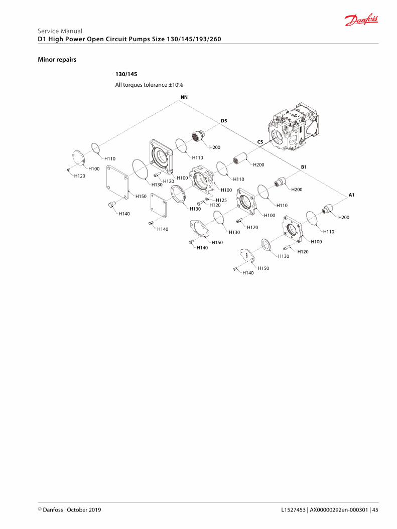
130/145
All torques tolerance ±10%
H140
H140
H140
H140
H110
H100H120
H150
H150
H150
H130
H130
H120
H120
H130
H130
H125H120
H120
H100
H100
H100
H100
H110
H110
H110
H110
H200
H200
H200
H200
NN
D5
C5
B1
A1
Service ManualD1 High Power Open Circuit Pumps Size 130/145/193/260
Minor repairs
© Danfoss | October 2019 L1527453 | AX00000292en-000301 | 45

193/260
All torques tolerance ±10%
A1/A3
NN
D2/D5
C5/C9
B1
E2 (E3)*
H200
H200
H200
H200
H110
H110
H110
H110
H100
H100
H100
H100
H120
H120
H120
H120
H200
H110H110H100H100
H120H120
H108
H105
H107
H130
H130
H130H130
H140
H140
H140H140
H140
H150
H150
H150H150
H130
H150
* E3 option is only for 260.
Service ManualD1 High Power Open Circuit Pumps Size 130/145/193/260
Minor repairs
46 | © Danfoss | October 2019 L1527453 | AX00000292en-000301
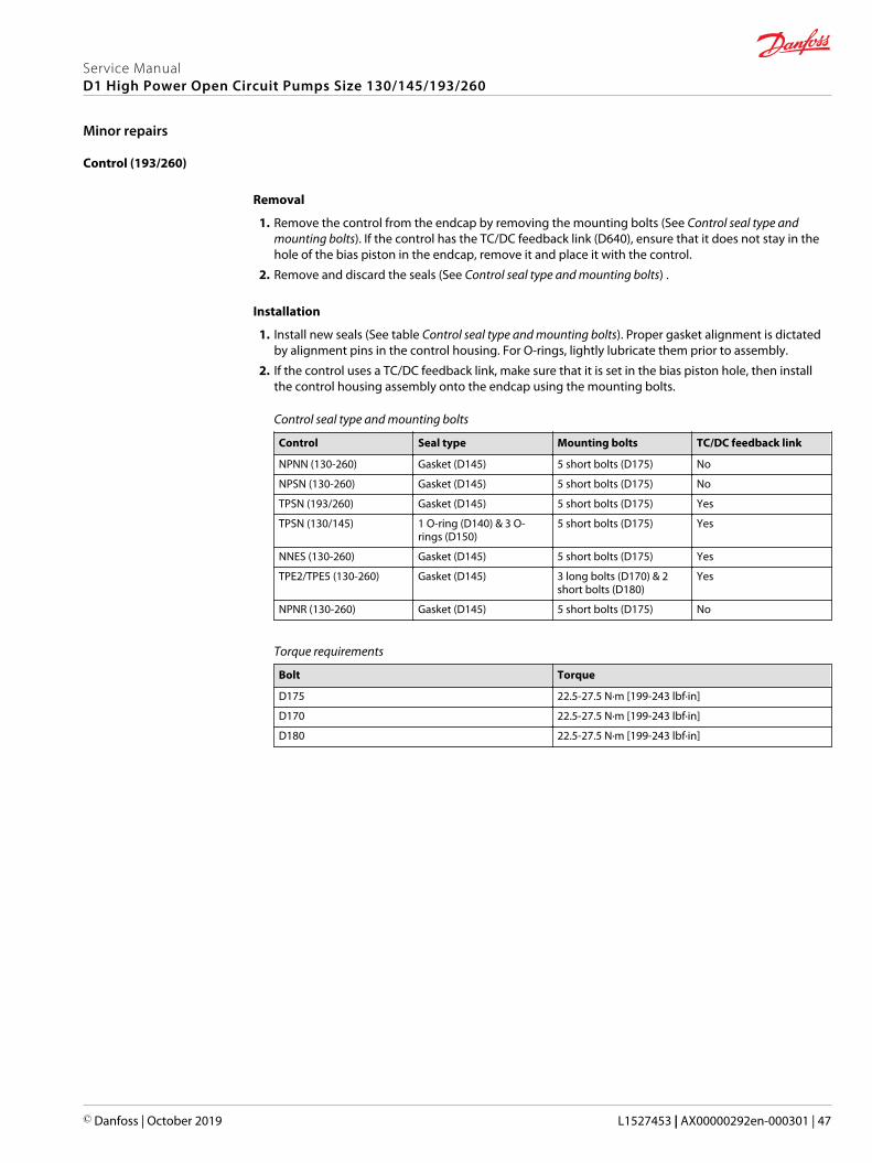
Control (193/260)
Removal
1. Remove the control from the endcap by removing the mounting bolts (See Control seal type andmounting bolts). If the control has the TC/DC feedback link (D640), ensure that it does not stay in thehole of the bias piston in the endcap, remove it and place it with the control.
2. Remove and discard the seals (See Control seal type and mounting bolts) .
Installation
1. Install new seals (See table Control seal type and mounting bolts). Proper gasket alignment is dictatedby alignment pins in the control housing. For O-rings, lightly lubricate them prior to assembly.
2. If the control uses a TC/DC feedback link, make sure that it is set in the bias piston hole, then installthe control housing assembly onto the endcap using the mounting bolts.
Control seal type and mounting bolts
Control Seal type Mounting bolts TC/DC feedback link
NPNN (130-260) Gasket (D145) 5 short bolts (D175) No
NPSN (130-260) Gasket (D145) 5 short bolts (D175) No
TPSN (193/260) Gasket (D145) 5 short bolts (D175) Yes
TPSN (130/145) 1 O-ring (D140) & 3 O-rings (D150)
5 short bolts (D175) Yes
NNES (130-260) Gasket (D145) 5 short bolts (D175) Yes
TPE2/TPE5 (130-260) Gasket (D145) 3 long bolts (D170) & 2short bolts (D180)
Yes
NPNR (130-260) Gasket (D145) 5 short bolts (D175) No
Torque requirements
Bolt Torque
D175 22.5-27.5 N·m [199-243 lbf·in]
D170 22.5-27.5 N·m [199-243 lbf·in]
D180 22.5-27.5 N·m [199-243 lbf·in]
Service ManualD1 High Power Open Circuit Pumps Size 130/145/193/260
Minor repairs
© Danfoss | October 2019 L1527453 | AX00000292en-000301 | 47
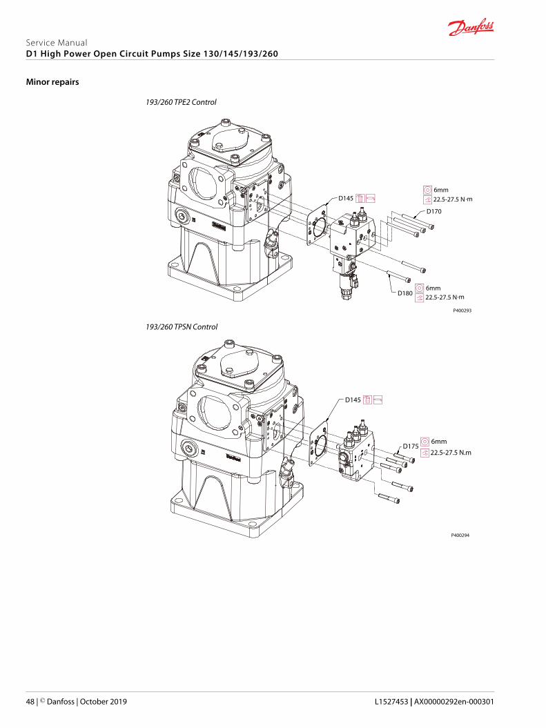
193/260 TPE2 Control
6mm
D170
D145 22.5-27.5 N·m
6mmD180 22.5-27.5 N·m
P400293
193/260 TPSN Control
P400294
6mmD175
22.5-27.5 N.
·
m
D145
Service ManualD1 High Power Open Circuit Pumps Size 130/145/193/260
Minor repairs
48 | © Danfoss | October 2019 L1527453 | AX00000292en-000301
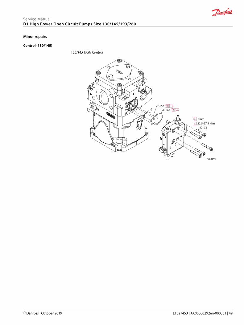
Control (130/145)
130/145 TPSN Control
D150D140
D175
P400259
6mm22.5-27.5 N·m
Service ManualD1 High Power Open Circuit Pumps Size 130/145/193/260
Minor repairs
© Danfoss | October 2019 L1527453 | AX00000292en-000301 | 49
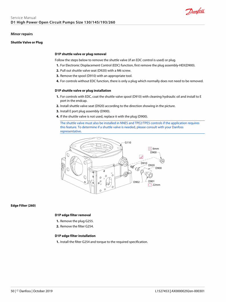
Shuttle Valve or Plug
D1P shuttle valve or plug removal
Follow the steps below to remove the shuttle valve (if an EDC control is used) or plug.
1. For Electronic Displacement Control (EDC) function, first remove the plug assembly-HEX(D900).
2. Pull out shuttle valve seat (D920) with a M6 screw.
3. Remove the spool (D910) with an appropriate tool.
4. For controls without EDC function, there is only a plug which normally does not need to be removed.
D1P shuttle valve or plug installation
1. For controls with EDC, coat the shuttle valve spool (D910) with cleaning hydraulic oil and install to Eport in the endcap.
2. Install shuttle valve seat (D920) according to the direction showing in the picture.
3. Install E port plug assembly (D900).
4. If the shuttle valve is not used, replace it with the plug (D900).
The shuttle valve must also be installed in NNES and TPE2/TPE5 controls if the application requiresthis feature. To determine if a shuttle valve is needed, please consult with your Danfossrepresentative.
D901D902
D900
D900
D920D910
G110
22mm
6mm
Edge Filter (260)
D1P edge filter removal
1. Remove the plug G255.
2. Remove the filter G254.
D1P edge filter installation
1. Install the filter G254 and torque to the required specification.
Service ManualD1 High Power Open Circuit Pumps Size 130/145/193/260
Minor repairs
50 | © Danfoss | October 2019 L1527453 | AX00000292en-000301

2. Install the plug G255 and torque to the required specification.
D900
D900D920
D901D902
D910
G255G254
Wrench size and torque
Item Wrench size Torque
G254 6mm hex 9.9-12.1 Nm
G255 6mm hex 30.6-37.4 Nm
D900 6mm hex 30.6-37.4 Nm
D901 22mm hex 30.6-37.4 Nm
Service ManualD1 High Power Open Circuit Pumps Size 130/145/193/260
Minor repairs
© Danfoss | October 2019 L1527453 | AX00000292en-000301 | 51

Displacement Limiters
D1P displacement limiter screws removal
The removal steps of the maximum (bottom of the pump) and minimum (top of the pump, control side)are the same.
1. Loosen the lock nut (F120) with an external hex wrench.
2. Counter clockwise turn the adjusting screw (F110) with an 8mm internal hex wrench until itcompletely out.
3. Inspect the lock nut seal and adjusting screw, if they are damaged , discard them.
D1P displacement limiter screws installation
The installation steps of the maximum (bottom of the pump) and minimum (top of the pump) are thesame.
1. Clockwise turn the adjusting screw (F110) with the appropriate internal hex wrench until you feel itstart against the swashplate.
2. Install the lock nut (F120), while holding the adjusting screw position, torque the lock nut to requiredtorque.
Wrench size and torque
Frame size Wrench size Torque
130/145cc 5 mm (screws) 17 mm(nuts)
43~48 N·m [380.58~424.84 lbf·in]
193cc 8 mm (screws), 24 mm(nuts)
180~206 N·m [1593.13~1823.25 lbf·in]
260cc 8 mm (screws), 24 mm(nuts)
180~206 N·m [1593.13~1823.25 lbf·in]
Service ManualD1 High Power Open Circuit Pumps Size 130/145/193/260
Minor repairs
52 | © Danfoss | October 2019 L1527453 | AX00000292en-000301

F110
F120
F110
F120 P400265
Service ManualD1 High Power Open Circuit Pumps Size 130/145/193/260
Minor repairs
© Danfoss | October 2019 L1527453 | AX00000292en-000301 | 53
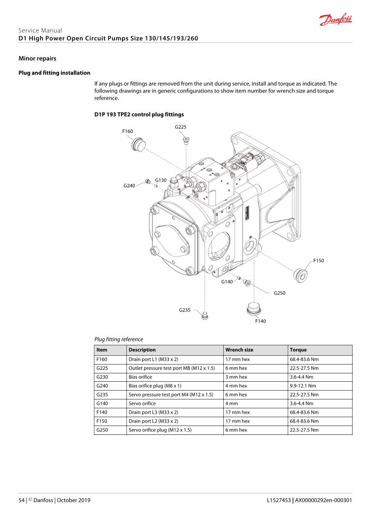
Plug and fitting installation
If any plugs or fittings are removed from the unit during service, install and torque as indicated. Thefollowing drawings are in generic configurations to show item number for wrench size and torquereference.
D1P 193 TPE2 control plug fittings
G235
G250
F140
F150
G225F160
G240G130
G140
Plug fitting reference
Item Description Wrench size Torque
F160 Drain port L1 (M33 x 2) 17 mm hex 68.4-83.6 Nm
G225 Outlet pressure test port MB (M12 x 1.5) 6 mm hex 22.5-27.5 Nm
G230 Bias orifice 3 mm hex 3.6-4.4 Nm
G240 Bias orifice plug (M8 x 1) 4 mm hex 9.9-12.1 Nm
G235 Servo pressure test port M4 (M12 x 1.5) 6 mm hex 22.5-27.5 Nm
G140 Servo orifice 4 mm 3.6-4.4 Nm
F140 Drain port L3 (M33 x 2) 17 mm hex 68.4-83.6 Nm
F150 Drain port L2 (M33 x 2) 17 mm hex 68.4-83.6 Nm
G250 Servo orifice plug (M12 x 1.5) 6 mm hex 22.5-27.5 Nm
Service ManualD1 High Power Open Circuit Pumps Size 130/145/193/260
Minor repairs
54 | © Danfoss | October 2019 L1527453 | AX00000292en-000301

D1P 260 TPE2 control plug fittings
G235
G250
G253
F140
F150
G255
G254
G130
G140
G225
F160
Plug fitting reference
Item Description Wrench size Torque
G130 Bias orifice 3 mm hex 3.6-4.4 Nm
G140 Servo orifice 4 mm 3.6-4.4 Nm
G225 Outlet pressure test port MB (M12 x 1.5) 6 mm hex 22.5-27.5 Nm
G235 Servo pressure test port M4 (M12 x 1.5) 6 mm hex 22.5-27.5 Nm
G250 Servo orifice plug (M12 x 1.5) 6 mm hex 22.5-27.5 Nm
G253 Bias orifice plug (5/16 - 24 UNF-2A) 1/8 in 9.9-12.1 Nm
G254 Edge filter 6 mm hex 9.9-12.1 Nm
G255 Edge filter plug (M14 x 1.5) 6 mm hex 30.6-37.4 Nm
F140 Drain port L3 (M33 x 2) 17 mm hex 68.4-83.6 Nm
F150 Drain port L2 (M33 x 2) 17 mm hex 68.4-83.6 Nm
F160 Drain port L1 (M33 x 2) 17 mm hex 68.4-83.6 Nm
Service ManualD1 High Power Open Circuit Pumps Size 130/145/193/260
Minor repairs
© Danfoss | October 2019 L1527453 | AX00000292en-000301 | 55

D1P 130/145 TPSN control plug fittings
G225
F160
G240
G130
G235G250
F140
F150G140
Plug fitting reference
Item Description Wrench size Torque
G130 Bias orifice 3 mm hex 3.6-4.4 Nm
G140 Servo orifice 4 mm 3.6-4.4 Nm
G225 Outlet pressure test port MB (M12 x 1.5) 6 mm hex 22.5-27.5 Nm
G235 Servo pressure test port M4 (M12 x 1.5) 6 mm hex 22.5-27.5 Nm
G250 Servo orifice plug (M14 x 1.5) 6 mm hex 30.6-37.4 Nm
F140 Drain port L3 (M26 x 1.5) 12 mm hex 68.4-83.6 Nm
F150 Drain port L2 (M26 x 1.5) 12 mm hex 68.4-83.6 Nm
F160 Drain port L1 (M26 x 1.5) 12 mm hex 68.4-83.6 Nm
Service ManualD1 High Power Open Circuit Pumps Size 130/145/193/260
Minor repairs
56 | © Danfoss | October 2019 L1527453 | AX00000292en-000301
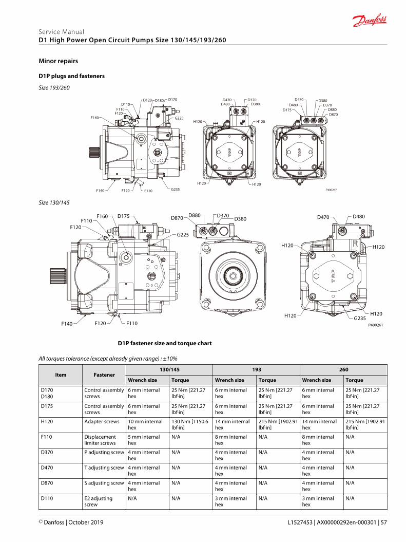
D1P plugs and fasteners
Size 193/260
F120
F140 F110 G235
H120 H120
H120 H120
F120
D180 D170
G225
D480 D380D175
D480D470
D370D380
D870D880
D370D470
F110D110
D120
F160
P400267
Size 130/145
F120
F140 F120 F110
F110F160 D175
G225
D870 D880 D370D380
H120
D470 D480
H120
H120G235H120
P400261
D1P fastener size and torque chart
All torques tolerance (except already given range) : ±10%
Item Fastener130/145 193 260
Wrench size Torque Wrench size Torque Wrench size Torque
D170D180
Control assemblyscrews
6 mm internalhex
25 N·m [221.27lbf·in]
6 mm internalhex
25 N·m [221.27lbf·in]
6 mm internalhex
25 N·m [221.27lbf·in]
D175 Control assemblyscrews
6 mm internalhex
25 N·m [221.27lbf·in]
6 mm internalhex
25 N·m [221.27lbf·in]
6 mm internalhex
25 N·m [221.27lbf·in]
H120 Adapter screws 10 mm internalhex
130 N·m [1150.6lbf·in]
14 mm internalhex
215 N·m [1902.91lbf·in]
14 mm internalhex
215 N·m [1902.91lbf·in]
F110 Displacementlimiter screws
5 mm internalhex
N/A 8 mm internalhex
N/A 8 mm internalhex
N/A
D370 P adjusting screw 4 mm internalhex
N/A 4 mm internalhex
N/A 4 mm internalhex
N/A
D470 T adjusting screw 4 mm internalhex
N/A 4 mm internalhex
N/A 4 mm internalhex
N/A
D870 S adjusting screw 4 mm internalhex
N/A 4 mm internalhex
N/A 4 mm internalhex
N/A
D110 E2 adjustingscrew
N/A N/A 3 mm internalhex
N/A 3 mm internalhex
N/A
Service ManualD1 High Power Open Circuit Pumps Size 130/145/193/260
Minor repairs
© Danfoss | October 2019 L1527453 | AX00000292en-000301 | 57
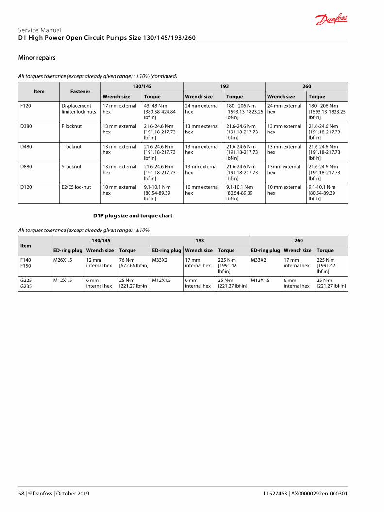
All torques tolerance (except already given range) : ±10% (continued)
Item Fastener130/145 193 260
Wrench size Torque Wrench size Torque Wrench size Torque
F120 Displacementlimiter lock nuts
17 mm externalhex
43 -48 N·m[380.58-424.84lbf·in]
24 mm externalhex
180 - 206 N·m[1593.13-1823.25lbf·in]
24 mm externalhex
180 - 206 N·m[1593.13-1823.25lbf·in]
D380 P locknut 13 mm externalhex
21.6-24.6 N·m[191.18-217.73lbf·in]
13 mm externalhex
21.6-24.6 N·m[191.18-217.73lbf·in]
13 mm externalhex
21.6-24.6 N·m[191.18-217.73lbf·in]
D480 T locknut 13 mm externalhex
21.6-24.6 N·m[191.18-217.73lbf·in]
13 mm externalhex
21.6-24.6 N·m[191.18-217.73lbf·in]
13 mm externalhex
21.6-24.6 N·m[191.18-217.73lbf·in]
D880 S locknut 13 mm externalhex
21.6-24.6 N·m[191.18-217.73lbf·in]
13mm externalhex
21.6-24.6 N·m[191.18-217.73lbf·in]
13mm externalhex
21.6-24.6 N·m[191.18-217.73lbf·in]
D120 E2/E5 locknut 10 mm externalhex
9.1-10.1 N·m[80.54-89.39lbf·in]
10 mm externalhex
9.1-10.1 N·m[80.54-89.39lbf·in]
10 mm externalhex
9.1-10.1 N·m[80.54-89.39lbf·in]
D1P plug size and torque chart
All torques tolerance (except already given range) : ±10%
Item130/145 193 260
ED-ring plug Wrench size Torque ED-ring plug Wrench size Torque ED-ring plug Wrench size Torque
F140F150
M26X1.5 12 mminternal hex
76 N·m[672.66 lbf·in]
M33X2 17 mminternal hex
225 N·m[1991.42lbf·in]
M33X2 17 mminternal hex
225 N·m[1991.42lbf·in]
G225G235
M12X1.5 6 mminternal hex
25 N·m[221.27 lbf·in]
M12X1.5 6 mminternal hex
25 N·m[221.27 lbf·in]
M12X1.5 6 mminternal hex
25 N·m[221.27 lbf·in]
Service ManualD1 High Power Open Circuit Pumps Size 130/145/193/260
Minor repairs
58 | © Danfoss | October 2019 L1527453 | AX00000292en-000301
Danfoss Power Solutions is a global manufacturer and supplier of high-quality hydraulic andelectric components. We specialize in providing state-of-the-art technology and solutionsthat excel in the harsh operating conditions of the mobile off-highway market as well as themarine sector. Building on our extensive applications expertise, we work closely with you toensure exceptional performance for a broad range of applications. We help you and othercustomers around the world speed up system development, reduce costs and bring vehiclesand vessels to market faster.
Danfoss Power Solutions – your strongest partner in mobile hydraulics and mobileelectrification.
Go to www.danfoss.com for further product information.
We offer you expert worldwide support for ensuring the best possible solutions foroutstanding performance. And with an extensive network of Global Service Partners, we alsoprovide you with comprehensive global service for all of our components.
Local address:
Danfoss Power Solutions GmbH & Co. OHGKrokamp 35D-24539 Neumünster, GermanyPhone: +49 4321 871 0
Danfoss Power Solutions ApSNordborgvej 81DK-6430 Nordborg, DenmarkPhone: +45 7488 2222
Danfoss Power Solutions (US) Company2800 East 13th StreetAmes, IA 50010, USAPhone: +1 515 239 6000
Danfoss Power Solutions Trading(Shanghai) Co., Ltd.Building #22, No. 1000 Jin Hai RdJin Qiao, Pudong New DistrictShanghai, China 201206Phone: +86 21 2080 6201
Danfoss can accept no responsibility for possible errors in catalogues, brochures and other printed material. Danfoss reserves the right to alter its products without notice. This also applies to productsalready on order provided that such alterations can be made without subsequent changes being necessary in specifications already agreed.All trademarks in this material are property of the respective companies. Danfoss and the Danfoss logotype are trademarks of Danfoss A/S. All rights reserved.
© Danfoss | October 2019 L1527453 | AX00000292en-000301
Products we offer:
• DCV directional controlvalves
• Electric converters
• Electric machines
• Electric motors
• Gear motors
• Gear pumps
• Hydrostatic motors
• Hydrostatic pumps
• Orbital motors
• PLUS+1® controllers
• PLUS+1® displays
• PLUS+1® joysticks andpedals
• PLUS+1® operatorinterfaces
• PLUS+1® sensors
• PLUS+1® software
• PLUS+1® software services,support and training
• Position controls andsensors
• PVG proportional valves
• Steering components andsystems
• Telematics
Hydro-Gearwww.hydro-gear.com
Daikin-Sauer-Danfosswww.daikin-sauer-danfoss.com
Recommended