all the support you need
S T R U C T U R E S

ContentsIntroduction
Projects and installations
Stage roof systems
Air roof
Introduction to truss
Miscellaneous additional trusses
Introduction to generic truss
Generic light duty truss
Generic medium duty truss
Generic heavy duty truss
Generic extra heavy duty truss
Introduction to element truss
Element 12 truss
Element 20 truss
Introduction to omni truss
Series 16 light duty truss
Series 16 medium duty truss
Series 16 heavy duty truss
Series 16 extra heavy duty truss
Omni connectors
Introduction to totalite
Totalite truss
Introduction to folding truss
Folding triangular truss
Fold flat medium duty truss
Fold flat heavy duty truss
Fold flat catwalk truss
Introduction to specialist truss
Par truss
Ballast truss
Catwalk truss
Introduction to newwave
A-wave
C-wave
Assembly data
Design help
Introduction to ground support
Ground support series 12
Ground support series 18
Introduction to V-Tower
V-Tower
Introduction to arena deck
Arena deck technical page
Arena deck construction
CM chain hoists
Motor control
Rigging accessories
Introduction to RSC Lightlock
The RSC Lightlock story
RSC Lightlock benefits & faqs
RSC Lightlock technical
Contents1
S T R U C T U R E S
2
3
8
14
16
17
18
19
20
21
22
23
24
25
26
27
28
29
33
34
35
36
37
43
45
46
47
48
49
50
51
54
55
56
13
30
31
38
40
41
42
52
53
57
61
62
63
64
65
66
15
Introduction 2
All the support you needTotal Structures is committed to creating and
providing the finest quality products with
outstanding customer support, and to further
our reputation as the industry's most creative
innovator and manufacturer of modular and
custom structural systems for the live
production, exhibition, architectural, retail and
entertainment markets.
From concept through installation, Total
Structures offers a range of professional
services, from our American Welding Society
certified fabrication team, professional
engineers, draftsmen and production
experienced sales team. We understand what it
will take to make your project safe and
successful. In a world of tight deadlines, ever
changing design parameters and financial
constraints, Total Structures offers All The
Support You Need….
Total Structures is the proud winner of the following Awards….
LDI Product of the year
Scenic Effects - XO truss series
LDI Product of the Year
Rigging and Hardware - The OMNI Connector
LDI Debuting Product of the Year
Rigging and Hardware - new wave truss
Rental and Staging Magazine
Product of the Year - new wave truss
The Exhibitor Show
Dealers Choice Award - new wave truss
PLASA
Award for Product Excellence - new wave truss
The Aluminum Association
International Extrusion of the Year - new wave extrusion
LDI Product of the Year
Rigging and Hardware - Ballast truss
PLASA
Gold Award for Innovation - RSC Lightlock
LDI
Best Debuting Product Award - RSC Lightlock
Live Design Magazine
Product of the Year - RSC Lightlock
1997
2000
2002
2002
2002
2003
2004
2004
2008
2009
2010

Projects and installations3
Introduction
University, Texas State Fair, Madonna
to name but a few. The following pages
seek to give you a flavor of some of the
more recent projects we have
undertaken.
These projects have involved Total
Structures from concept through
design, engineering, manufacture to
installation, but of course the most
important project is the next one we do
for you….
Over the course of many years, Total
Structures has been at the forefront of
many cutting edge projects and
installations. From the technically
challenging to those whose sheer scale
has been impressive and of course
those projects that seem to have it all:
The Nike pavilion at the Atlanta
Olympics with its 15000 sq./ft cantilever
built atop a parking garage. The
beautiful star array at a desert casino,
the custom stage roofs, or the 8000
sq./ft temporary restaurant assembled
each year to house Vanity Fairs Oscar
party. There have been Superbowls,
Rock and Roll Shows, Theatre Houses,
TV Shows, Bungie Jumps, Underwater
Rigging, Triple decked exhibit booths.
There have been Projects for Ford, GM,
Nike, Disney, Fox, Universal, BBC,
Budweiser, Anhuiser Busch, Stanford
Projects and installations

S T R U C T U R E S
Projects and installations 4
Projects and installations

Hollywood Bowl
The new acoustic canopy measures
some 78 feet by 68 feet and is supported
at a 10 degree angle below the main roof
structure by inclined tubular steel struts.
The principal components of the canopy
are an elliptical perimeter ladder truss
with integral catwalk, 4 cross stage
triangular trusses which support 28
acoustic panels and 3 lighting battens.
The perimeter truss has curved 6"
square aluminum chords with 3"
diagonals and 6" x 3" vertical members
onto which ribbed plates are bolted to
form the supports for a continuous open
grid aluminum catwalk. These ribs are
formed from aluminum plate that were
water jet cut to the correct profile to
provide support for the curved fiber
glass panels which cover the underside
of the ellipse.
The side sections of the perimeter truss
can be lowered to stage level to allow
conventional lighting grids to be rigged
from the points provided on the steel
arch trusses of the main roof structure.
In contrast, the front and rear sections
are permanently fixed to the main roof
structure with large tubular steel struts.
Four large triangular trusses span
between elements of the perimeter
truss and carry the main hinged
acoustic panels. These panels are
fabricated with aluminum ribs which
support matte Makrolon panels on one
side and can be deployed at various
angles using remote controlled linear
actuators. The trusses comprise 4"
square aluminum chords with 2" square
secondary members and the end
sections are designed to hinge down,
so that the truss better fits the profile of
Projects and installations5
Projects and installations
the domed main roof structure when it is
raised into its storage position.
Three ladder truss lighting battens span
between sections of the perimeter truss.
Again, the chords are 4" square
aluminum with 2" diagonals with
galvanized steel l ight ing bars
supported from the bottom chord. The
battens can also be raised above the
perimeter ring truss and stored high into
the main roof structure.
The interaction of the main roof
structure and the acoustic canopy
presented a number of interesting
structural engineering problems
particularly when seismic and wind
forces were considered.

Projects and installations 6
S T R U C T U R E S
The brief for the project was to create a
"Corporate Box" that would house all the
Ford brands (Ford, Lincoln, Mercury,
Mazda, Volvo, Jaguar, Land Rover, Aston
Martin) in an enclosed space. The "Box"
description is literal as what was required
was a ceiling and walls on three sides
containing a space 460ft x 240ft (over
110,000 square ft) x 28ft high. The entire
structure was then to be clad in fabric
leaving only exposed lighting troughs that
were required to be large enough to
house all the fixtures and provide room for
focusing. It was crucial to the design that
no part of any lighting fixture was hanging
below the ceiling surface.
The truss was designed large enough so
that it could house 4 individual adjustable
light bars to allow any fixture (including
automated fixtures) to be mounted in its
optimal position in the truss, and also to
be pre-rigged. A further consideration
was that the bottom face of the truss was
to be free of members so that they did not
interfere with focusing and positioning of
In addition to the ceiling grid, a structural
wall system was developed to construct
the 460ft walls required along each side.
This had to carry its own self weight, the
tension of the fabrics attached to it, a
plywood skin on each side behind the
fabric (to stop anyone falling through the
wall) and also to carry wooden dowel
panels around the access openings which
were part of the finished dressing. Total
Structures developed a new system of
horizontal and vertical ladders on approx
10ft centers that formed the thickness of
the wall, and into which could be
accommodated the 4 traffic and exit points
along each side.
It is believed that the entire rig is probably
the largest "Temporary Lighting Grid" ever
assembled as a single structure and
required 216 motor points to lift it.
the lamps, and also so that there was no
visible structure from the ground. The
careful location of internal bracing
allowed this to happen.
The grid was then made up from 24 rows x
240ft long cross stage trusses on 20ft
centers with a perimeter truss and
additional spreader trusses at the ¼ span
points. Many of the building columns and
the support structure for the city's people
mover train had to be incorporated into
the space, and where these interfered
with the grid, custom truss elements had
to be made to accommodate them and
provide a structure that the ceiling fabric
could be attached to.
In addition, a 40ft diameter circle (known
as the "Ford Halo") was also included as
part of the structure over the Ford brand
area and a 6ft pelmet was required to
finish the ceiling at the open front
entrance of the exhibit.
Ford Motor Company NAIAS 2006
Some stats....
Approx 2.5KM of truss was used
Around 5 million individual weld points
Approx 55 tons of Aluminum
50000sq ft of painted area (Truss and
wall metalwork only)

Projects and installations7
To provide "the ultimate solution for lighting,
sound and video" for their church in
Colorado Springs, New Life Church
commissioned Barbizon.
For the structure that would compliment this
"Church in the round", Barbizon turned to
Total Structures with whom they had a long
standing relationship, cemented since
commissioning their award-winning LDI
booth in 2000.
The solution was a 120' span hexagonal
catwalk connected to a central cluster of 6 x
14' by 10 ½' rear projection screens that
housed the rear projectors and provided the
mainstage lighting position, suspended 25
feet in the air . The hexagonal catwalk, 50
feet on each side, provided additional
lighting positions with 4 x 2" integral
lampbars providing hanging points for
lighting and other equipment, non-slip steel
decking for high resistance to wear and
integral kick rails.
New Life Church
Projects and installations

Stage roof systems 8
Client:
Project:
Set & scenic:
Live 4 Live
Stanford commencement
San Diego Opera Shop
Client:
Project:
Architects:
Fabric Structures Inc
Summerstage, Central Park, New York
FTL Happold
Stage roof systems
1. 2.
1.
2.
Total Structures manufactures what is probably the
most versatile modular stage roof system in the
world, detailed information for which is contained in
the coming pages. However, please note that we
have a long history of designing and manufacturing
custom stage roofs that are tailored precisely to
meet our clients needs, some examples of which are
illustrated in the inset photographs.
Please contact us for a consultation to help you
decide which roof format would best suit your
needs. +1 805 676 3322, or if you would like us to
c o n t a c t y o u , p l e a s e e - m a i l u s o n

S T R U C T U R E S
Stage roof systems9
The Total Structures' Outdoor Stage Roof Design is
now the world wide industry standard, with systems in
every major country. The flexibility in the concept
makes it the most versatile, expandable roof system in
the market today. A typical structure has a perimeter
grid made up of standard truss which would usually be
10ft sections, although other modules can be
accomodated. The width and depth of the roof is
determined by the number of modules in each
direction. The maximum allowable cross stage span is
80ft (larger custom construction can be achieved), with
virtually no limit on the depth. The roof is formed by
constructing a matrix of ladders and truss which make
a series of identically sized bays inside the structure. It
is this feature which gives rise to massive point load
capacities anywhere under the grid.
The payload of the roof is governed primarily by the
number and type of towers at each side and a choice of
perimeter truss: Medium Duty, Heavy Duty, Fold Flat or
even Folding Catwalk Truss. Similarly payloads range
from 6 Tons for small roofs to 25 Tons and above for
larger constructions. The roof is covered with high grade
reinforced PVC material which is divided into pieces on
large roofs for easy handling.
The concept of the roof structure is so versitile that a large
roof can be split into two separate smaller roofs by adding
only a small number of components.
Integral PA wings of various sizes can be added to the
main roof structure for a major concert or tour.
As the majority of components are essentially two
dimensional, the structure requires very little volume for
transport and storage, especially when the fold flat or
folding catwalk truss are used around the perimeter. With
each intersection using only four bolts, the largest of roof
constructions can be achieved remarkably quickly with a
minimum crew.
Stage roof systems

S T R U C T U R E S
10Stage roof systems

Stage roof systems11
Stage roof systems
Specification
The illustrations on this page demonstrate the modular
nature of the Total Structures Outdoor Roof System.
The components used in the largest system can be
reconfigured to make many other roof assemblies,
including all those illustrated.
Three-dimensional CAD models are offered with every
quotation along with a detailed component list so that
the client can assess precisely what is being
purchased.
Onsite training is provided where necessary and each
roof is supplied with an operating manual. Full
engineering is supplied with each system and is
defined by US Unified Building Code, conformity to
ANSI E1.21-2006 “Entertainment Technology Ground-
Supported Overhead Structures Used to Cover the
Stage Areas and Support Equipment in the Production
of Outdoor Entertainment Events”, and also in
consultation with the client to determine special
considerations such as local and state requirements
and operational conditions. Total Structures also make
a commitment to clients with after sales support, not
only with product supply and maintenance, but also
with engineering and advice.
45ft x 45ft Stage Roof - 4 towers 45ft x 45ft Stage Roof w/ 10ft single span sound wing - 4 towers
65ft x 45ft Stage Roof - 6 towers
65ft x 45ft Stage Roof
25ft x 25ft Apex sound wings - 10 towers
65ft x 55ft Stage Roof w/ Cantilevered DS edge
& 35ft x 25ft continuous slope sound wings 10 towers.
65ft x 55ft Stage Roof - 8 towers

19
22
2
9
2
18
17
1615
15
15
15
16
17
18
19
22
22
22
23
23
23
23
21
21
21
21
20
20
20
20
11
11
11
11
7
7
7
7
7
3
3
2
2
1
1
2
2
12
12
12
12
13
13
13
13
2
2
4
4
5
5
6
6
8
8
8
8
8
9
9
9
9
10
10
10
10
10
14
14
14
14
S T R U C T U R E S
Stage roof systems 12
The exploded view on this page is given to
demonstrate the ease of assembly and also to
provide a key to terminology used specifically for
Total Structures Stage Roof assemblies. This
illustration is taken from the Total Structures
publication “Operating Manual for Demountable
Roof Top Structures Designed and Fabricated by
Total Structures Inc”, which is provided with all our
stage roof systems.
Sleeve Block
Perimeter Truss
Level 1 Sloping Truss
Level 2 Sloping Truss
Level 3 Sloping Truss
Level 4 Sloping Truss
Level 1 Apex Ladder
Level 2 Apex Ladder
Level 3 Apex Ladder
Level 4 Apex Ladder
Level 1 Sloping Ladder
Level 2 Sloping Ladder
Level 3 Sloping Ladder
Level 4 Sloping Ladder
Sloping Ladder > Truss Node
Apex Ladder > Truss Node Level 1
Apex Ladder > Truss Node Level 2
Apex Ladder > Truss Node Level 3
Apex Ladder > Truss Node Level 4
Level 1 Grid Node
Level 2 Grid Node
Level 3 Grid Node
Level 4 Grid Node
2
1
3
4
5
6
7
8
9
10
11
12
13
14
15
16
17
18
19
20
21
22
23
Air Roof
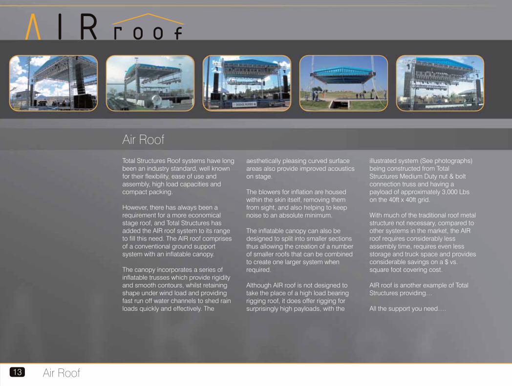
Total Structures Roof systems have long been an industry standard, well known for their flexibility, ease of use and assembly, high load capacities and compact packing.
However, there has always been a requirement for a more economical stage roof, and Total Structures has added the AIR roof system to its range to fill this need. The AIR roof comprises of a conventional ground support system with an inflatable canopy.
The canopy incorporates a series of inflatable trusses which provide rigidity and smooth contours, whilst retaining shape under wind load and providing fast run off water channels to shed rain loads quickly and effectively. The
aesthetically pleasing curved surface areas also provide improved acoustics on stage.
The blowers for inflation are housed within the skin itself, removing them from sight, and also helping to keep noise to an absolute minimum.
The inflatable canopy can also be designed to split into smaller sections thus allowing the creation of a number of smaller roofs that can be combined to create one larger system when required.
Although AIR roof is not designed to take the place of a high load bearing rigging roof, it does offer rigging for surprisingly high payloads, with the
illustrated system (See photographs) being constructed from Total Structures Medium Duty nut & bolt connection truss and having a payload of approximately 3,000 Lbs on the 40ft x 40ft grid.
With much of the traditional roof metal structure not necessary, compared to other systems in the market, the AIR roof requires considerably less assembly time, requires even less storage and truck space and provides considerable savings on a $ vs. square foot covering cost.
AIR roof is another example of Total Structures providing…
All the support you need….
Air Roof13
1414Intro to truss
S T R U C T U R E S
introduction
trussTotal Structures manufactures a full range of both industry standard and proprietary trusses that cover most requirements. However, if you do not find what you need here, or require assistance in selecting the appropriate product, please call us on +1 805 676 3322 or e-mail us at [email protected] where we will be happy to assist you and, if necessary, help design a custom product to meet your specific requirements.
All Total Structures Truss products are designed and manufactured to conform to ANSI Standard E1.2-2006 and all published load data is inclusive of the standards required 15% reduction in capacity to account for multiple use wear and tear.

Uniform Loads Center Pt. Load Third Pt. Load Quarter Pt. Load
(ft) (plf) (lbs) (in)
span load defl
(lbs) (in) (lbs) (lbs)(in) (in)
load deflload deflload deflload
Generic truss15
A small selection of miscellaneous additional available trusses Load Data 30" x 30" wide heavy duty truss with 3/16" wall
thickness chords and reinforced plates
Uniform Loads Center Pt. Load Third Pt. Load Quarter Pt. Load
(ft) (plf) (lbs) (in)
span load defl
(lbs) (in) (lbs) (lbs)(in) (in)
load deflload deflload deflload
Load data 30" x 36" truss with steel fork or omni connection Load data 30" x 30" wide heavy duty truss
Uniform Loads Center Pt. Load Third Pt. Load Quarter Pt. Load
(ft) (plf) (lbs) (in)
span load defl
(lbs) (in) (lbs) (lbs)(in) (in)
load deflload deflload deflload
10
20
30
40
50
60
70
80
90
100
989
488
321
207
128
85
59
42
31
16
9886
9759
9631
8266
6383
5086
4122
3368
2753
1581
0.018
0.145
0.488
1.014
1.584
2.281
3.105
4.055
5.132
5.155
4434
4307
4179
4052
3192
2543
2061
1684
1376
790
0.013
0.103
0.345
0.808
1.296
1.884
2.594
3.433
4.408
4.584
2217
2153
2090
2026
1962
1898
1546
1263
1032
593
0.011
0.088
0.296
0.697
1.351
2.316
3.161
4.124
5.213
5.228
2793
2750
2708
2066
1596
1271
1031
842
688
395
0.019
0.155
0.520
0.966
1.512
2.182
2.977
3.900
4.951
5.012
5
10
15
20
25
30
35
40
45
50
55
60
1925
958
636
420
266
182
132
99
76
60
48
39
9624
9581
9539
8408
6650
5464
4604
3949
3430
3006
2652
2349
0.005
0.037
0.126
0.265
0.414
0.596
0.811
1.059
1.341
1.655
2.003
2.384
6571
6528
5655
4204
3325
2732
2302
1975
1715
1503
1326
1175
0.005
0.041
0.120
0.213
0.334
0.482
0.659
0.864
1.100
1.365
1.662
1.992
3285
3264
3243
3153
2494
2049
1727
1481
1286
1127
994
881
0.004
0.035
0.117
0.271
0.423
0.609
0.828
1.081
1.368
1.687
2.041
2.427
3208
3194
2828
2102
1663
1366
1151
987
858
752
663
587
0.006
0.047
0.142
0.252
0.394
0.567
0.773
1.011
1.280
1.583
1.918
2.286
10
20
30
40
50
60
70
80
782 7820 0.020
387 7740 0.170
238 7140 0.530
130 5200 0.950
80 4000 1.500
53 3180 2.180
36 2520 2.990
26 2080 3.950
7825 0.030
5470 0.190
3572 0.440
2600 0.780
1999 1.240
1583 1.830
1273 2.540
1030 3.400
3912 0.030
3867 0.230
2679 0.550
1950 1.000
1499 1.550
1188 2.240
955 3.080
772 4.050
2608 0.030
2578 0.210
1786 0.510
1300 0.920
1000 1.450
792 2.100
637 2.900
515 3.830
18" x 18" Truss24" x 24" Truss Generic Medium Duty Truss with 3/16" wall thickness chords
Uniform Loads Center Pt. Load Third Pt. Load Quarter Pt. Load
(ft) (plf) (lbs) (in)
span load defl
(lbs) (in) (lbs) (lbs)(in) (in)
load deflload deflload deflload
External Dimensions 30" w. x 36" h.Connection Centers 28" x 34"Material Type 6061-T6 Aluminum
Connector Type Steel Fork or Omni ConnectorsMaximum Certified Span 100ft
External Dimensions 30" w. x 30" h.Connection Centers 23.28" x 23.28"Material Type 6061-T6 AluminumConnector Type 5/8" Grade 8 Steel nuts boltsMaximum Certified Span 60ft
External Dimensions 30" w. x 30" h.Connection Centers 23.28" x 23.28"Material Type 6061-T6 Aluminum
5
10
15
20
25
30
35
40
45
50
55
60
1293 6466 0.005 4922 0.006 2461 0.005 2155 0.006
643 6428 0.041 4883 0.049 2442 0.042 2143 0.051
426 6390 0.137 4436 0.152 2423 0.142 2130 0.173
318 6352 0.325 3294 0.271 2403 0.335 1647 0.321
208 5201 0.527 2600 0.425 1950 0.538 1300 0.501
142 4264 0.758 2132 0.614 1599 0.774 1066 0.722
102 3584 1.032 1792 0.840 1344 1.054 896 0.984
77 3064 1.348 1532 1.103 1149 1.376 766 1.287
59 2651 1.706 1326 1.404 994 1.740 663 1.631
46 2314 2.107 1157 1.745 868 2.147 578 2.016
37 2030 2.549 1015 2.127 761 2.596 508 2.444
30 1788 3.034 894 2.551 670 3.087 447 2.913
External Dimensions 24" w. x 24" h.
Connection Centers 17.28" x 17.28"
Material Type 6061-T6 Aluminum
Connector Type 5/8" Grade 8 Steel nuts & bolts
Maximum Certified Span 60ft Span
Uniform Loads Center Pt. Load Third Pt. Load Quarter Pt. Load
(ft) (plf) (lbs) (in)
span load defl
(lbs) (in) (lbs) (lbs)(in) (in)
load deflload deflload deflload
5
10
15
20
25
30
35
40
45
50
55
60
1241 6204 0.005 6204 0.008 3102 0.006 2068 0.006
616 6162 0.038 6162 0.061 3081 0.052 2054 0.048
408 6119 0.129 5604 0.187 3060 0.174 2040 0.162
304 6077 0.305 4166 0.333 3038 0.412 2026 0.384
241 6034 0.595 3295 0.522 2471 0.662 1647 0.617
180 5413 0.933 2706 0.755 2030 0.953 1353 0.888
130 4561 1.270 2280 1.031 1710 1.296 1140 1.210
98 3911 1.659 1955 1.353 1467 1.693 978 1.582
75 3396 2.099 1698 1.722 1274 2.141 849 2.005
60 2976 2.592 1488 2.138 1116 2.642 744 2.478
48 2624 3.136 1312 2.604 984 3.195 656 3.003
39 2324 3.732 1162 3.120 871 3.800 581 3.579
External Dimensions 20-1/2" w. x 20-1/2" h.
Connection Centers 13.78" x 13.78"
Material Type 6061-T6 Aluminum
Connector Type 5/8" Grade 8 Steel nuts & bolts
Maximum Certified Span 60ft
Uniform Loads Center Pt. Load Third Pt. Load Quarter Pt. Load
(ft) (plf) (lbs) (in)
span load defl
(lbs) (in) (lbs) (lbs)(in) (in)
load deflload deflload deflload
1219 6095 0.009 4928 0.012 2464 0.010 2032 0.011
606 6063 0.072 4870 0.093 2448 0.080 2021 0.092
402 6031 0.244 3220 0.209 2415 0.266 1610 0.248
239 4774 0.463 2387 0.373 1790 0.474 1194 0.441
150 3762 0.724 1881 0.585 1411 0.740 941 0.689
103 3077 1.043 1538 0.846 1154 1.065 769 0.994
74 2578 1.419 1289 1.158 967 1.448 645 1.354
55 2196 1.854 1098 1.522 823 1.891 549 1.771
42 1892 2.346 946 1.939 709 2.392 473 2.244
33 1642 2.897 821 2.412 616 2.951 411 2.775
26 1432 3.505 716 2.942 537 3.568 358 3.364
17 1019 3.577 509 3.057 382 3.635 255 3.447
5
10
15
20
25
30
35
40
45
50
55
60
External Dimensions 18" w. x 18" h.
Connection Centers 11.28" x 11.28"
Material Type 6061-T6 Aluminum
Connector Type 5/8" Grade 8 Steel nuts & bolts
Maximum Certified Span 60ft
Connector Type 5/8" Grade 8 Steel nuts & boltsMaximum Certified Span 80ft

16
generic S T R U C T U R E S
Introduction to Generic Truss
Generic Light Duty truss is a compact
design that is ideal in situations where
ceiling height is limited and for carrying
simple lighting loads and accessories
such as drapes and scenery. Two
standard profiles are available, 12” h x
12” w and 12” h x 18” w. The wide
version allows 2 rows of fixtures to
hang side by side without interfering
with each other and is sometimes
referred to as “Ball room truss”.
Generic Heavy Duty is, as its name
suggests, is ideal for situations where
long spans (up to 60ft) or high load
capacities are required. Two formats,
30” h. x 20.5” w. and 30” h. x 30” w. are
available. The widths accommodating
Series 12 and Series 18 Ground support
towers respectively and both can be
used as a base for the Total Structures
outdoor stage roof system.
Triangular versions of these trusses are
avai lable, but should only be
considered when a triangular profile is
specifically required, as load capacity is
substantially reduced while cost is not!
Generic Medium Duty is perhaps the
truss that the production industry is built
on. GMD has good structural properties
and can achieve span lengths up to 50ft.
With a 20.5” square cross section it
provides a very economical truck pack
and great versatility and can be used as
a base for the Total Structures outdoor
stage roof system.
Built on the same profile, S4-PRT is a
Pre-rigged version of this truss that is
physically and structurally compatible,
that will house a lamp bar of fixtures
(ideal for Source 4 Par lamps) that can
be stored in the truss for shipping and
storage, and lowered through the truss
at show time.
Generic Light Duty Truss Generic Medium Duty Truss Generic Heavy Duty Truss
Our Generic truss range is the most commonly available truss type in North America and
possibly the world. Simple and durable, this range has been the workhorse of the industry for
many years. A bolted butt splice connection is simple, inexpensive and easy to use and perfect
for most general-purpose applications.
Generic XHD is not really “generic”, it
is Total Structures proprietary solution
for when seriously long spans and
high load capacity is required. As it
has a bolted connection it finds itself
in the Generic range. If XHD (“extra”
heavy duty) still doesn't provide the
span or capacity you require, then as
with the rest of the Generic range, an
OMNI version with fork connectors
can be found on page 28.
Generic XHD
Intro to Generic truss

12"w. x 12"h.
6.78"w. x 6.78"h.
6061-T6 Aluminum
5/8" Grade 8 Steel nuts & bolts
40ft
Also available in 12" x 18" wide format
5
10
15
20
25
30
35
40
767
381
252
145
91
61
44
23
3836
3809
3781
2894
2266
1837
1524
933
0.02
0.12
0.40
0.73
1.14
1.64
2.23
2.24
1307
1279
1251
1224
1133
919
762
467
0.01
0.06
0.21
0.50
0.92
1.34
1.83
1.87
653
640
626
612
598
584
570
350
0.01
0.05
0.18
0.43
0.84
1.44
2.27
2.28
646
637
628
619
566
459
381
233
0.01
0.08
0.25
0.60
1.08
1.56
2.13
2.15
Uniform Loads Center Pt. Load Third Pt. Load Quarter Pt. Load
(ft) (plf) (lbs) (in)
span load defl
(lbs) (in) (lbs) (lbs)(in) (in)
load deflload deflload deflload
5
10
15
20
25
30
35
40
665
331
150
83
52
31
15
7
3327
3308
2256
1658
1292
939
529
291
0.03
0.20
0.47
0.84
1.31
1.72
1.72
1.72
0.01
0.11
0.37
0.68
1.07
1.41
1.45
1.50
568
559
549
540
485
352
199
109
0.01
0.09
0.32
0.75
1.34
1.76
1.75
1.75
561
555
549
415
323
235
132
73
0.02
0.13
0.44
0.80
1.25
1.64
1.65
1.66
1137
1117
1098
829
646
469
265
146
3d viewTruss Features
S T R U C T U R E S
Generic truss17
Generic Light Duty Truss
Description Specification
External Dimensions
Connection Centers
Material Type
Connector Type
Maximum Certified Span
Notes
Part No Description
LD1210FN
LD128FN
LD125FN
LD123MN
LD122MN
LD121MN
LDC122N
LDC123N
LDC124N
LDC125N
LDC126N
LDT1210FN
LDT128FN
LDT125FN
LDT123MN
LDT122MN
LDT121MN
LDTC122N
LDTC123N
LDTC124N
LD1810FN
LD188FN
LD185FN
LD183MN
LD182MN
LD181MN
LDC182N
LDC183N
LDC184N
10ft section Bolted connection
8ft section Bolted connection
5ft section Bolted connection
3m section Bolted connection
2m section Bolted connection
1m section Bolted connection
2 way corner section Bolted connection
3 way corner section Bolted connection
4 way corner section Bolted connection
5 way corner section Bolted connection
6 way corner section Bolted connection
10ft section Bolted connection
8ft section Bolted connection
5ft section Bolted connection
3m section Bolted connection
2m section Bolted connection
1m section Bolted connection
2 way corner section Bolted connection
3 way corner section Bolted connection
4 way corner section Bolted connection
10ft section Bolted connection
8ft section Bolted connection
5ft section Bolted connection
3m section Bolted connection
2m section Bolted connection
1m section Bolted connection
2 way corner section Bolted connection
3 way corner section Bolted connection
4 way corner section Bolted connection
59
48
37
59
42
24
26
31
35
40
44
48
38
27
48
32
18
16
25
34
66
53
42
65
46
31
27
32
36
WT (lbs)
3d view
Product
Light
Duty
12” x 12”
Light
Duty
Triangular
Light
Duty
12” x 18”
Load Data Triangular
Dimensions
Load Data 12 x 12” and 12 x 18”Component Weights
0.7"
12.0"
6.8"
6.8" 12.0"

Component Weights
3d viewDimensions Truss Features
S T R U C T U R E S
Generic truss 18
Generic Medium Duty Truss
Description Specification
External Dimensions
Connection Centers
Material Type
Connector Type
Maximum Certified Span
1 120- /2" w. x 20- /2”h.
13.78" x 13.78"
6061-T6 Aluminum
5/8" Grade 8 Steel nuts & bolts
50ft
Part No Description
MD10FN
MD8FN
MD5FN
MD3MN
MD2MN
MD1MN
MDC2N
MDC3N
MDC4N
MDC5N
MDC6N
10ft section Bolted connection
8ft section Bolted connection
5ft section Bolted connection
3m section Bolted connection
2m section Bolted connection
1m section Bolted connection
2 way corner section Bolted connection
3 way corner section Bolted connection
4 way corner section Bolted connection
5 way corner section Bolted connection
6 way corner section Bolted connection
84
63
52
84
58
35
35
46
55
64
73
WT (lbs)
MDT10FN
MDT8FN
MDT5FN
MDT3MN
MDT2MN
MDT1MN
MDTC2N
MDTC3N
MDTC4N
10ft section Bolted connection
8ft section Bolted connection
5ft section Bolted connection
3m section Bolted connection
2m section Bolted connection
1m section Bolted connection
2 way corner section Bolted connection
3 way corner section Bolted connection
4 way corner section Bolted connection
58
49
37
58
40
23
25
37
50
5
10
15
20
25
30
35
40
45
50
1243
618
410
277
175
119
86
64
49
39
6213
6179
6145
5532
4364
3575
3001
2562
2213
1927
0.01
0.06
0.19
0.40
0.63
0.90
1.23
1.60
2.03
2.51
4926
4892
3728
2766
2182
1787
1500
1281
1107
964
0.01
0.07
0.18
0.32
0.51
0.73
1.00
1.31
1.67
2.08
2463
2446
2429
2074
1637
1340
1125
961
830
723
0.01
0.06
0.20
0.41
0.64
0.92
1.25
1.64
2.07
2.55
2472
2460
1864
1383
1091
894
750
640
553
482
0.01
0.08
0.21
0.38
0.60
0.86
1.17
1.53
1.94
2.40
Uniform Loads Center Pt. Load Third Pt. Load Quarter Pt. Load
(ft) (plf) (lbs) (in)
span load defl
(lbs) (in) (lbs) (lbs)(in) (in)
Load Data - Medium Square
load deflload deflload deflload
5
10
15
20
25
30
35
40
45
50
1056
525
280
155
97
66
47
35
27
21
4435
3180
2098
1552
1218
992
826
699
597
514
0.02
0.09
0.21
0.37
0.58
0.83
1.14
1.50
1.92
2.39
2218
2205
1574
1164
914
744
620
524
448
385
0.01
0.11
0.26
0.46
0.73
1.04
1.42
1.85
2.34
2.89
1760
1590
1049
776
609
496
413
350
299
257
0.02
0.11
0.24
0.43
0.68
0.98
1.33
1.74
2.21
2.73
5280
5254
4197
3103
2437
1984
1653
1399
1195
1027
0.01
0.09
0.26
0.46
0.71
1.02
1.39
1.82
2.30
2.84
TriangularLoad Data - Triangular
0.7"
20.5"
13.8" 20.5"
13.8"

Generic truss19
S T R U C T U R E SGeneric Heavy Duty Truss
Component Weights
3d view DimensionsTruss Features
Load Data
Description Specification
External Dimensions
Connection Centers
Material Type
Connector Type
Maximum Certified Span
Notes
120- /2"w. x 30"h.
13.78" x 23.28"
6061-T6 Aluminum5/8” Grade 8 Steel nuts & bolts
60ft
Also available in 30" x 30" wide format. See page 15 for WHD tables
Part No Description
HD10FN
HD8FN
HD5FN
HD3MN
HD2MN
HD1MN
HDC2N
HDC3N
HDC4N
10ft section Bolted connection
8ft section Bolted connection
5ft section Bolted connection
3m section Bolted connection
2m section Bolted connection
1m section Bolted connection
2 way corner section Bolted connection
3 way corner section Bolted connection
4 way corner section Bolted connection
88
73
61
88
66
44
38
47
56
WT (lbs)
5
10
15
20
25
30
35
40
45
50
55
60
1939
966
641
421
267
183
132
100
77
61
49
40
9696
9658
9620
8425
6672
5489
4634
3983
3468
3049
2699
2400
0.01
0.04
0.13
0.27
0.41
0.60
0.81
1.06
1.34
1.66
2.01
2.38
4922
4883
4845
4213
3336
2745
2317
1992
1734
1524
1349
1200
0.01
0.03
0.10
0.21
0.33
0.48
0.66
0.86
1.10
1.36
1.66
1.98
2461
2442
2423
2403
2384
2059
1738
1494
1301
1143
1012
900
0.01
0.03
0.09
0.21
0.40
0.61
0.83
1.08
1.37
1.69
2.04
2.43
2470
2458
2445
2106
1668
1372
1159
996
867
762
675
600
0.01
0.04
0.12
0.25
0.39
0.57
0.77
1.01
1.28
1.58
1.92
2.28
Uniform Loads Center Pt. Load Third Pt. Load Quarter Pt. Load
(ft) (plf) (lbs) (in)
span load defl
(lbs) (in) (lbs) (lbs)(in) (in)
load deflload deflload deflload
0.7"
20.5"
13.8"
23.3"
30.0"

S T R U C T U R E S Generic Extra Heavy Duty Truss
Component Weights
10
20
30
40
50
60
70
80
90
100
1852
691
300
163
99
65
44
27
11
3
18518
13821
8987
6503
4957
3882
3075
2125
1033
285
0.027
0.161
0.363
0.645
1.008
1.451
1.975
2.352
2.352
2.352
9784
6911
4494
3251
2479
1941
1537
1062
516
143
0.023
0.13
0.293
0.526
0.83
1.211
1.673
2.041
2.137
2.271
4892
4824
3370
2438
1859
1456
1153
797
387
107
0.019
0.154
0.37
0.658
1.027
1.478
2.008
2.387
2.376
2.361
4921
3455
2247
1626
1239
970
769
531
258
71
0.027
0.153
0.345
0.615
0.963
1.931
1.899
2.274
2.298
2.322
Uniform Loads Center Pt. Load Third Pt. Load Quarter Pt. Load
(ft) (plf) (lbs) (in)
span load defl
(lbs) (in) (lbs) (lbs)(in) (in)
Load Data
Part No Description WT (lbs)
load deflload deflload deflload
3d viewDimensions
Description Specification
Truss Features
Generic truss 20
External Dimensions
Connection Centers
Material Type
Connector Type
Maximum Certified Span
24"w. x 48"h.
17.28"w. x 41.28"h.
6061-T6 Aluminum
5/8" Grade 8 Steel nuts & bolts
100ft
XHD10FN
XHD8FN
XHD5FN
XHD3MN
XHD2MN
XHD1MN
XHDC2N
XHDC3N
XHDC4N
10ft section Bolted connection
8ft section Bolted connection
5ft section Bolted connection
3m section Bolted connection
2m section Bolted connection
1m section Bolted connection
2 way corner section Bolted connection
3 way corner section Bolted connection
4 way corner section Bolted connection
140
129
83
140
121
75
57
71
84
24.0"
17.3"
41.3" 48.0"
element Introduction to Element Truss
Element 12 has a compact design
that is ideal in situations where
ceiling height is limited and for
carrying simple lighting loads and
accessories such as drapes and
scenery. Two standard profiles are
available, 12” h x 12” w and 12” h x
18” w. The wide version allows 2
rows of fixtures to hang side by side
without interfering with each other
and is sometimes referred to as
“Ball room truss”.
Element 20 has good structural
properties and can achieve span
lengths up to 50ft. With a 20.5” square
cross section it provides a very
economical truck pack and great
versatility and can be used as a base
for the Total Structures outdoor stage
roof system
Triangular versions of these trusses
are available, but should only be
considered when a triangular profile is
specifically required, as load capacity
is substantially reduced while cost
is not!
Element 12 Element 20
Element truss represents the “value engineering” of the Generic Truss range to improve the structural characteristics of the truss while removing unnecessary elements and therefore providing greater economy. The trusses in this range are compatible with their generic truss counterparts, providing that the load information for the Generic Truss is observed and utilized where truss types are mixed.
S T R U C T U R E S
Element truss21
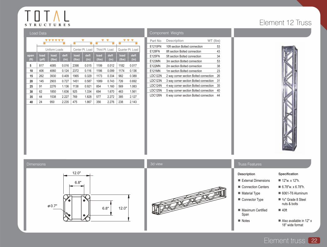
S T R U C T U R E S Element 12 Truss
Component Weights
Uniform Loads Center Pt. Load Third Pt. Load Quarter Pt. Load
(ft) (plf) (lbs) (in)
span load defl
(lbs) (in) (lbs) (lbs)(in) (in)
Load Data
Part No Description
E1210FN
E128FN
E125FN
E123MN
E122MN
E121MN
LDC122N
LDC123N
LDC124N
LDC125N
LDC126N
10ft section Bolted connection
8ft section Bolted connection
5ft section Bolted connection
3m section Bolted connection
2m section Bolted connection
1m section Bolted connection
2 way corner section Bolted connection
3 way corner section Bolted connection
4 way corner section Bolted connection
5 way corner section Bolted connection
6 way corner section Bolted connection
53
43
34
53
38
23
26
31
35
40
44
WT (lbs)
load deflload deflload deflload
3d viewDimensions
Description Specification
External Dimensions
Connection Centers
Material Type
Connector Type
Maximum Certified Span
Notes
12"w. x 12"h.
6.78"w. x 6.78"h.
6061-T6 Aluminum
5/8" Grade 8 Steel nuts & bolts
40ft
Also available in 12" x 18" wide format
Truss Features
Element truss 22
5
10
15
20
25
30
35
40
817
406
262
145
91
62
44
24
4085
4060
3930
2903
2276
1850
1538
950
0.016
0.124
0.409
0.727
1.136
1.636
2.227
2.235
2398
2372
1965
1451
1138
925
769
475
0.015
0.116
0.329
0.587
0.921
1.334
1.828
1.867
1199
1186
1173
1089
854
694
577
356
0.012
0.099
0.334
0.743
1.160
1.670
2.272
2.276
1182
1174
982
726
569
463
385
238
0.017
0.136
0.389
0.692
1.083
1.561
2.127
2.143
0.7"
12.0"
6.8"
6.8" 12.0"
Element truss23
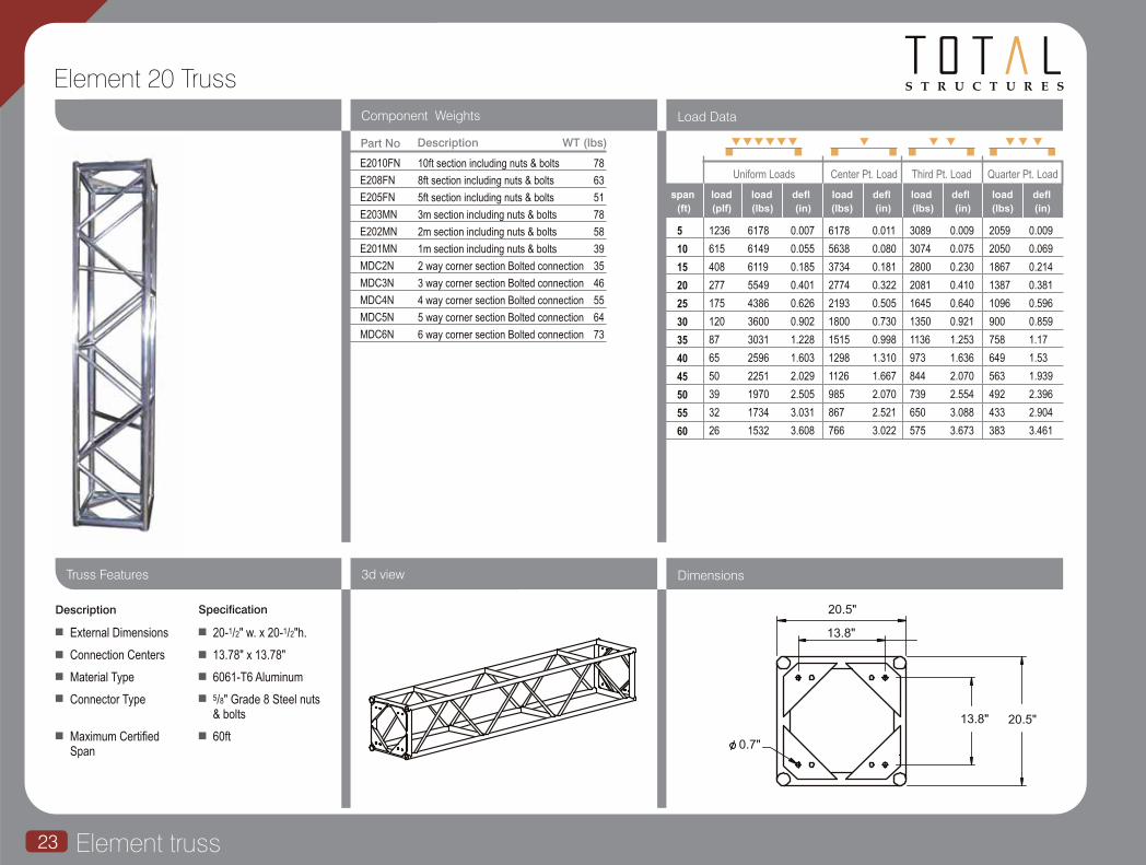
S T R U C T U R E SElement 20 Truss
Component Weights
Uniform Loads Center Pt. Load Third Pt. Load Quarter Pt. Load
(ft) (plf) (lbs) (in)
span load defl
(lbs) (in) (lbs) (lbs)(in) (in)
Load Data
Part No Description
E2010FN
E208FN
E205FN
E203MN
E202MN
E201MN
MDC2N
MDC3N
MDC4N
MDC5N
MDC6N
10ft section including nuts & bolts
8ft section including nuts & bolts
5ft section including nuts & bolts
3m section including nuts & bolts
2m section including nuts & bolts
1m section including nuts & bolts
2 way corner section Bolted connection
3 way corner section Bolted connection
4 way corner section Bolted connection
5 way corner section Bolted connection
6 way corner section Bolted connection
78
63
51
78
58
39
35
46
55
64
73
WT (lbs)
load deflload deflload deflload
Description Specification
External Dimensions
Connection Centers
Material Type
Connector Type
Maximum Certified Span
1 120- /2" w. x 20- /2"h.
13.78" x 13.78"
6061-T6 Aluminum
5/8" Grade 8 Steel nuts & bolts
60ft
5
10
15
20
25
30
35
40
45
50
55
60
1236
615
408
277
175
120
87
65
50
39
32
26
6178
6149
6119
5549
4386
3600
3031
2596
2251
1970
1734
1532
0.007
0.055
0.185
0.401
0.626
0.902
1.228
1.603
2.029
2.505
3.031
3.608
6178
5638
3734
2774
2193
1800
1515
1298
1126
985
867
766
0.011
0.080
0.181
0.322
0.505
0.730
0.998
1.310
1.667
2.070
2.521
3.022
3089
3074
2800
2081
1645
1350
1136
973
844
739
650
575
0.009
0.075
0.230
0.410
0.640
0.921
1.253
1.636
2.070
2.554
3.088
3.673
2059
2050
1867
1387
1096
900
758
649
563
492
433
383
0.009
0.069
0.214
0.381
0.596
0.859
1.17
1.53
1.939
2.396
2.904
3.461
3d view DimensionsTruss Features
0.7"
20.5"
13.8" 20.5"
13.8"

S T R U C T U R E S
omni Introduction to Omni TrussLDI Product of the Year 2000
Rigging and Hardware
The patented OMNI connection system is the most versatile truss connection system available anywhere and offers a stronger and more versatile variant to both the Element and Generic truss ranges (both of which can be retro fitted with OMNI connectors).OMNI is a rotating fork connector that combines the additional structural strength of a direct chord connection and an ability to provide a hinge point in any direction. This means that custom corner sections are a thing of the past! In addition to this, OMNI connectors are designed to be removable, thus allowing the truss to be used with generic truss and accessories with conventional bolt plates.
OMNI is available to fit both 1/8” wall (Type 8) and 3/16” wall (Type 16) and are deliberately not compatible, to avoid the dangers of mixing either in a span. OMNI series 8 is available as a retro fit; engineering is available on request or from www.totalstructures.com.
Omni truss 24Omni connector US patent No. 6675546
S T R U C T U R E S
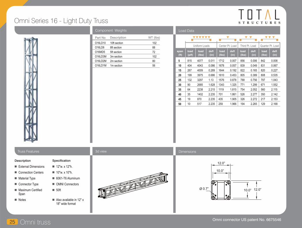
Omni truss25
Omni Series 16 - Light Duty Truss
Component Weights
Uniform Loads Center Pt. Load Third Pt. Load Quarter Pt. Load
(ft) (plf) (lbs) (in)
span load defl
(lbs) (in) (lbs) (lbs)(in) (in)
Load Data
Part No Description
O16LD10
O16LD8
O16MD5
O16LD3M
O16LD2M
O16LD1M
10ft section
8ft section
5ft section
3m section
2m section
1m section
102
88
72
102
80
56
WT (lbs)
load deflload deflload deflload
3d view Dimensions
Description Specification
External Dimensions
Connection Centers
Material Type
Connector Type
Maximum Certified Span
Notes
12"w. x 12"h.
10"w. x 10"h.
6061-T6 Aluminum
OMNI Connectors
50ft
Also available in 12" x 18" wide format
Truss Features
5
10
15
20
25
30
35
40
45
50
815
404
267
199
132
90
64
35
19
10
4077
4043
4009
3975
3297
2685
2238
1402
870
517
0.011
0.086
0.289
0.686
1.13
1.628
2.215
2.235
2.235
2.235
1712
1678
1644
1610
1576
1343
1119
701
435
259
0.007
0.057
0.192
0.453
0.878
1.325
1.815
1.861
1.905
1.966
856
839
822
805
788
771
754
526
326
194
0.006
0.049
0.165
0.389
0.756
1.299
2.052
2.277
2.272
2.265
842
831
820
808
797
671
560
350
217
129
0.008
0.067
0.227
0.535
1.043
1.552
2.115
2.142
2.153
2.168
0.7”
12.0”
10.0”
Ø 12.0” 10.0”
Omni connector US patent No. 6675546
S T R U C T U R E S
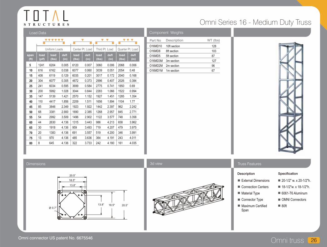
Omni truss 26
Omni Series 16 - Medium Duty Truss
Component Weights
Uniform Loads Center Pt. Load Third Pt. Load Quarter Pt. Load
(ft) (plf) (lbs) (in)
span load defl
(lbs) (in) (lbs) (lbs)(in) (in)
Load Data
Part No Description
O16MD10
O16MD8
O16MD5
O16MD3M
O16MD2M
O16MD1M
10ft section
8ft section
5ft section
3m section
2m section
1m section
128
103
87
127
96
67
WT (lbs)
load deflload deflload deflload
3d viewDimensions
Description Specification
External Dimensions
Connection Centers
Material Type
Connector Type
Maximum Certified Span
20-1/2" w. x 20-1/2"h.
18-1/2"w. x 18-1/2"h.
6061-T6 Aluminum
OMNI Connectors
80ft
Truss Features
5
10
15
20
25
30
35
40
45
50
55
60
65
70
75
80
1241
616
408
304
241
200
147
110
85
68
54
44
30
20
13
8
6204
6162
6119
6077
6034
5992
5139
4417
3846
3381
2992
2630
1918
1383
970
645
0.005
0.038
0.129
0.305
0.595
1.028
1.421
1.856
2.349
2.900
3.509
4.136
4.136
4.136
4.136
4.136
6120
6077
6035
4672
3699
3044
2570
2209
1923
1690
1496
1315
959
691
485
322
0.007
0.060
0.201
0.373
0.584
0.844
1.152
1.511
1.922
2.385
2.902
3.443
3.493
3.557
3.636
3.733
3060
3039
3017
2996
2775
2283
1927
1656
1442
1268
1122
986
719
519
364
242
0.006
0.051
0.172
0.407
0.741
1.066
1.451
1.894
2.397
2.957
3.577
4.213
4.207
4.200
4.191
4.180
2068
2054
2040
2026
1850
1522
1285
1104
962
845
748
658
479
346
243
161
0.006
0.48
0.168
0.384
0.69
0.994
1.354
1.77
2.242
2.771
3.358
3.962
3.975
3.991
4.011
4.035
20.5”
18.5"
13.8”
0.7ӯ
13.8” 18.5" 20.5”
Omni connector US patent No. 6675546
S T R U C T U R E S
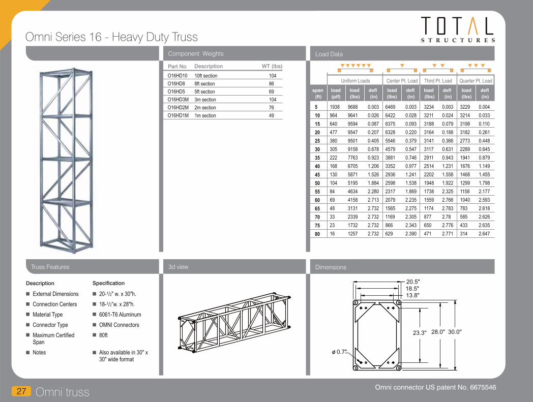
Omni truss27
Omni Series 16 - Heavy Duty Truss
Component Weights
Uniform Loads Center Pt. Load Third Pt. Load Quarter Pt. Load
(ft) (plf) (lbs) (in)
span load defl
(lbs) (in) (lbs) (lbs)(in) (in)
Load Data
Part No Description
O16HD10
O16HD8
O16HD5
O16HD3M
O16HD2M
O16HD1M
10ft section
8ft section
5ft section
3m section
2m section
1m section
104
86
69
104
76
49
WT (lbs)
load deflload deflload deflload
3d view Dimensions
Description Specification
External Dimensions
Connection Centers
Material Type
Connector Type
Maximum Certified Span
Notes
120- /2" w. x 30"h.
118- /2”w. x 28"h.
6061-T6 Aluminum
OMNI Connectors
80ft
Also available in 30" x 30" wide format
Truss Features
5
10
15
20
25
30
35
40
45
50
55
60
65
70
75
80
1938
964
640
477
380
305
222
168
130
104
84
69
48
33
23
16
9688
9641
9594
9547
9501
9158
7763
6705
5871
5195
4634
4158
3131
2339
1732
1257
0.003
0.026
0.087
0.207
0.405
0.678
0.923
1.206
1.526
1.884
2.280
2.713
2.732
2.732
2.732
2.732
6469
6422
6375
6328
5546
4579
3881
3352
2936
2598
2317
2079
1565
1169
866
629
0.003
0.028
0.093
0.220
0.379
0.547
0.746
0.977
1.241
1.538
1.869
2.235
2.275
2.305
2.343
2.390
3234
3211
3188
3164
3141
3117
2911
2514
2202
1948
1738
1559
1174
877
650
471
0.003
0.024
0.079
0.188
0.366
0.631
0.943
1.231
1.558
1.922
2.325
2.766
2.783
2.78
2.776
2.771
3229
3214
3198
3182
2773
2289
1941
1676
1468
1299
1158
1040
783
585
433
314
0.004
0.033
0.110
0.261
0.448
0.645
0.879
1.149
1.455
1.798
2.177
2.593
2.618
2.626
2.635
2.647
0.7"
20.5"
13.8"
23.3" 30.0"
18.5"
28.0"
Omni connector US patent No. 6675546

S T R U C T U R E S
28Omni truss
Omni Series 16 - Extra Heavy Duty Truss
Component Weights
Uniform Loads Center Pt. Load Third Pt. Load Quarter Pt. Load
(ft) (plf) (lbs) (in)
span load defl
(lbs) (in) (lbs) (lbs)(in) (in)
Load Data
Part No Description WT (lbs)
load deflload deflload deflload
3d viewDimensions
Description Specification
Truss Features
10
20
30
40
50
60
70
80
90
100
1849
917
501
275
170
113
79
42
20
8
0.018
0.147
0.413
0.734
1.147
1.651
2.248
2.352
2.352
2.352
9611
9450
7511
5492
4248
3392
2757
1683
909
385
0.015
0.122
0.333
0.595
0.937
1.362
1.875
2.012
2.091
2.2
4806
4725
4644
4119
3186
2544
2068
1263
682
289
0.013
0.104
0.35
0.749
1.17
1.683
2.289
2.39
2.381
2.369
5779
5725
3755
2746
2124
1696
1379
842
455
193
0.022
0.174
0.393
0.699
1.094
1.579
2.154
2.267
2.287
2.314
O16XHD10
O16XHD8
O16XHD5
O16XHD3M
O16XHD2M
O16XHD1M
10ft section
8ft section
5ft section
3m section
2m section
1m section
203
193
134
207
183
124
External Dimensions
Connection Centers
Material Type
Connector Type
Maximum Certified Span
24"w. x 48"h.
22"w. x 46"h.
6061-T6 Aluminum
OMNI Connectors
100ft
18493
18331
15021
10983
8496
6784
5515
3367
1818
770
24.0"
22.0"
46.0" 48.0"
Omni connector US patent No. 6675546
Omni truss29
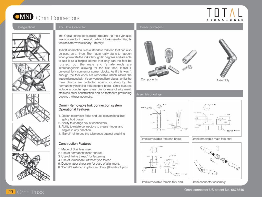
S T R U C T U R E SOmni Connectors
Connector images
Omni removable female fork end Omni connector assembly
Omni removable fork end barrel Omni removable male fork end
Assembly drawings
Configurations
Components Assembly
The OMNI connector is quite probably the most versatile truss connector in the world. Whilst it looks very familiar, its features are "revolutionary" - literally!
Its first incarnation is as a standard fork end that can also be used as a hinge. The magic really starts to happen when you rotate the forks through 90 degrees and are able to use it as a hinged corner. Not only can the fork be rotated, but the male and female ends are interchangeable allowing for the first time, TOTALLY universal fork connector corner blocks. As if this wasn't enough the fork ends are removable which allows the truss to be used with it's conventional bolt plates, whilst the main chords are protected against crushing by the permanently installed fork receptor barrel. Other features include a double taper shear pin for ease of alignment, stainless steel construction and no fasteners protruding beyond the truss geometry.
The Omni Connector
Omni - Removable fork connection system
Operational Features
1. Option to remove forks and use conventional butt splice bolt plates.
2. Ability to change sex of connectors.3. Ability to rotate connectors to create hinges and
angles in any direction.4. "Barrel" reinforces the tube ends against crushing
Construction Features
1. Made of Stainless steel.2. Use of permanent insert "Barrel".3. Use of "inline thread" for fastening.4. Use of "American Buttress" type thread.5. Double taper shear pin for ease of alignment.6. "Barrel" Fastened in place w/ Spirol (Brand) roll pins.
Omni connector US patent No. 6675546

totalite
Introduction to
Totalite truss 30
S T R U C T U R E S
We are proud to introduce an entirely new
truss line to our product range. TOTALITE
is a lightweight, durable, European style,
conical connection truss that is
manufactured in US standard increments.
An extensive stock of the 12" box version
in 10, 8, 5, and 2ft truss sections and a full
range of corners, bases and accessories
are available for immediate dispatch.
We introduced TOTALITE in response to a
demand for this inexpensive style of truss
in a non-metric format. The lightweight,
but structurally strong design of this style
of truss now dominates the exhibition
halls of Europe, but has been slow to
catch on in the US due to it's previous
unavailability in US standard lengths and
long lead t imes from European
manufacturers.
TOTALITE fills a hole in our product range
between our New Wave truss range and
our Light Duty rigging truss, and is lighter,
less expensive and more appropriate for
the exhibition, conference, television,
decorative and small show market.
Despite its decorative looks, easy
portability and low cost, TOTALITE is very
much a performance product and has
surprisingly high load capacity due to the
direct chord connection between trusses
and excellent geometry between main
chords and diagonal bracing. A 20' span
supports a uniformly distributed load
(U.D.L.) of 3,000 Lbs with only a 2"
deflection.
Like all Total Structures truss products it is
highly modular and can be configured in a
number of different ways.
All standard TOTALITE products are
available from inventory from our California
Head office.
TOTALITE is just another example of Total
Structures providing….
...all the support you need.

Totalite truss31
S T R U C T U R E S
Component Weights
3d view DimensionsTruss Features
Part No Description
TL21212
TL21210
TL21208
TL21206
TL21205
TL21212
TL21204
TL21203
TL21202
TL21201
TLC212L45
TLC212L60
TLC212L90
TLC212L120
TLC212L135
TLC212T
TLC212X
TLC212LVARC
TLC212LVAR
TLC212LD
TLC212TD
TLC212XD
TLC212XUD
12ft Totalite Truss
10ft Totalite Truss
8ft Totalite Truss
6ft Totalite Truss
5ft Totalite Truss
4ft Totalite Truss
3ft Totalite Truss
2ft Totalite Truss
1ft Totalite Truss
45 Degree 2 way Totalite corner
60 Degree 2 way Totalite corner
90 Degree 2 way Totalite corner
120 Degree 2 way Totalite corner
135 Degree 2 way Totalite corner
T-Style 3 way Totalite corner
X-Style 3 way Totalite corner
Totalite variable corner
Totalite locking variable corner
90 Degree & leg down 3 way Totalite corner
T-Style & leg down 4 way Totalite corner
X-Style & leg down 5 way Totalite corner
X-Style leg up & down 6 way Totalite corner
Cornerblock 1-6 dir. - corner
WT (lbs)
5
10
15
20
25
30
35
40
45
50
725
363
242
150
96
67
47
31
22
16
3626
3626
3626
3006
2405
2004
1629
1248
986
798
0.04
0.31
1.04
2.05
3.20
4.61
5.95
6.80
7.65
8.50
3626
3006
2004
1503
1202
1002
859
752
616
499
0.06
0.41
0.92
1.64
2.56
3.69
5.02
6.55
7.65
8.50
1813
1813
1503
1127
902
752
598
458
362
293
0.05
0.42
1.18
2.09
3.27
4.71
5.95
6.80
7.65
8.50
1209
1209
1002
752
601
501
429
329
260
210
0.05
0.39
1.09
1.95
3.04
4.38
5.95
6.80
7.65
8.50
Uniform Loads Center Pt. Load Third Pt. Load Quarter Pt. Load
(ft) (plf) (lbs) (in)
span load defl
(lbs) (in) (lbs) (lbs)(in) (in)
Load Data - Totalite
load deflload deflload deflload
Description Specification
External Dimensions
Connection Centers
Material Type
Connector Type
Maximum Certified Span
Tube wall thickness
1 111- /2" w. x 11- /2"h.
9.45" x 9.45"
6082-T6 Aluminum
Proprietary Conical
50ft
2mm
9.449"11.417"
45
90
9.449" 11.417"
49
40
32
24
20
16
12
8
4
33
27
13
13
13
16
19
18
18
17
20
23
27
13
S T R U C T U R E S
Component Weights
3d view Truss Features
Totalite truss 32
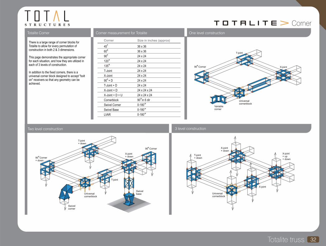
Corner measurement for Totalite
45
60
90
120
135
T-Joint
X-Joint
90 + D
T-Joint + D
X-Joint + D
X-Joint + D + U
Cornerblock
Swivel Corner
Swivel Base
LVAR
36 x 36
36 x 36
24 x 24
24 x 24
24 x 24
24 x 24
24 x 24
24 x 24
24 x 24
24 x 24 x 24
24 x 24 x 24
0-180
0-180
0-180
90 in 6 dir
Corner Size in inches (approx)
Totalite Corner
3 level constructionTwo level construction
One level construction
T-joint
X-joint
Universalcornerblock
Variablecorner
90 Corner
T-joint+ down
X-joint+ down
90 Corner
90 Corner+ down
Swivelcorner
Universalcornerblock
T-joint
Swivelbase Universal
cornerblock
T-joint+ down
X-joint+ down
X-joint
X-joint+ up+ down
Corner
There is a large range of corner blocks for Totalite to allow for every permutation of construction in both 2 & 3 dimensions.
This page demonstrates the appropriate corner for each situation, and how they are utilized in each of 3 levels of construction.
In addition to the fixed corners, there is a universal corner block designed to accept "bolt on" receivers so that any geometry can be achieved.
S T R U C T U R E S
Folding truss33
folding Folding Triangular truss is the oldest in
the range and has been available for
over 15 years. Lightweight and robust,
a 40ft span packs into the same space
as an 8ft pre-rig truss. The truss
comprises of a pair of hinging ladders
with locking elbow braces. The
locking elbows are permanently
attached which means they are
always in the correct place and cannot
be lost, important as misplaced or lost
braces could result in a structural
failure.
The original Fold Flat Truss updated to
include new hinging mechanisms to
improve robustness. The truss is
typically fabricated using 2” x 3/16”
wall main chords and fixed fork end
connections for speed of assembly
and measures 30” x 20 ½” when open,
but closes down to only 6” for reduced
transportation and storage volume.
Hinging V braces lock the truss in the
open format and connected to
brackets on the main chords using
quarter turn Camloc fasteners with
butterfly or hex head fittings. The
vertical hinging frames incorporate
diagonals to provide torsional
resistance to the truss.
Medium duty fold flat uses the same
patented technology as the original
fold f lat truss. The hinging
mechanisms have been updated to
improve robustness.
The truss is typically fabricated using
2” x 3/16” wall main chords and fixed
fork end connections for speed of
assembly and measures 20 ½” x 20
½” when open, but closes down to
only 6” for reduced transportation and
storage volume. Hinging V braces
lock the truss in the open format and
connected to brackets on the main
chords using quarter turn Camloc
fasteners with butterfly or hex head
fittings. The vertical hinging frames
incorporate diagonals to provide
torsional resistance to the truss.
Folding Triangular truss MD Fold Flat truss HD Fold Flat truss
The folding truss series offers a variety of products that serve to fulfill a number of truss
requirements, but also fold to allow a greater economy of truck and storage space.
Working on the same principle as the
other Fold Flat Trusses in the range, the
plan bracing is in the bottom of the truss
and incorporates a platform to allow a
more comfortable work space on the
truss. It should be noted that this does
not provide a strict catwalk and all usual
safety procedures for working at height
on truss should be followed. If a “true”
catwalk is required that meets OSHA
standards, then we recommend Fixed
Catwalk truss.
The truss is typically fabricated using 2”
x 3/16” wall main chords and fixed fork
end connections for speed of
assembly. The truss measures 35” x 26
½” when open, but closes down to only
6” for reduced transportation and
storage volume.
Fold Flat Catwalk truss
Introduction to Folding Truss

S T R U C T U R E S
Folding truss 34
Component Weights
Uniform Loads Center Pt. Load Third Pt. Load Quarter Pt. Load
(ft) (plf) (lbs) (in)
span load defl
(lbs) (in) (lbs) (lbs)(in) (in)
Load Data
Part No Description WT (lbs)
load deflload deflload deflload
3d viewDimensions Truss Features
Folding Triangular Truss
FT10F
FT8F
FT5F
FT4F
FTC2
FTC3
FTC4
10ft section
8ft section
5ft section
4ft section
2 way corner section
3 way corner section
4 way corner section
81
70
53
48
66
77
88
Description Specification
External Dimensions
Connection Centers
Material Type
Connector Type
Maximum Certified Span
Please refer drawing
Please refer drawing
6061-T6 Aluminum
Aluminum Fork
50ft
5
10
15
20
25
30
35
40
45
50
1123
558
370
276
210
144
104
78
60
47
5616
5582
5548
5514
5255
4317
3637
3119
2708
2373
0.01
0.04
0.13
0.32
0.59
0.85
1.16
1.52
1.92
2.37
3713
3679
3645
3323
2628
2159
1819
1559
1354
1186
0.01
0.04
0.14
0.31
0.48
0.69
0.94
1.24
1.57
1.95
1857
1840
1823
1806
1789
1619
1364
1170
1016
890
0.01
0.04
0.12
0.28
0.55
0.87
1.19
1.55
1.96
2.41
1872
1861
1849
1661
1314
1079
909
780
677
593
0.01
0.05
0.17
0.36
0.56
0.81
1.11
1.45
1.83
2.27
26.0"
4.0"
27.9"
20.8"

Folding truss35
S T R U C T U R E SFold Flat Medium Duty Truss
Component Weights Load Data
Part No Description WT (lbs)
3d view DimensionsTruss Features
Uniform Loads Center Pt. Load Third Pt. Load Quarter Pt. Load
(ft) (plf) (lbs) (in)
span load defl
(lbs) (in) (lbs) (lbs)(in) (in)
load deflload deflload deflload
FFT3M
FFT2M
FFT1M
FFTC4
FFTS4N
3m section
2m section
1m section
4 way corner section
4 way sleeve section
112
84
56
88
96
Description Specification
External Dimensions
Connection Centers
Material Type
Connector Type
Maximum Certified Span
1 120- /2"w. x 20- /2"h.
1 118- /2"w. x 18- /2”h.
6061-T6 Aluminum
Steel fork ends
80ft
20.5"
18.5"
18.5"
20.5"
10
20
30
40
50
60
70
80
615
303
199
108
65
43
19
7
6153
6060
5955
4303
3274
2557
1323
577
0.038
0.305
1.026
1.825
2.851
4.106
4.136
4.136
4793
4583
2978
2151
1637
1278
662
288
0.047
0.367
0.83
1.489
2.352
3.433
3.582
3.775
2396
2350
2233
1614
1228
959
496
216
0.04
0.322
1.048
1.862
2.907
4.181
4.197
4.176
2051
2020
1489
1076
819
639
331
144
0.048
0.383
0.977
1.741
2.727
3.938
3.997
4.046

S T R U C T U R E S
Folding truss 36
Fold Flat Heavy Duty Truss
Component Weights
Uniform Loads Center Pt. Load Third Pt. Load Quarter Pt. Load
(ft) (plf) (lbs) (in)
span load defl
(lbs) (in) (lbs) (lbs)(in) (in)
Load Data
Part No Description WT (lbs)
load deflload deflload deflload
3d viewDimensions Truss Features
HFFT3M
HFFT2M
HFFT1M
HFFTC4
HFFTS4N
3m section
2m section
1m section
4 way corner section
4 way sleeve section
123
87
62
90
9810
15
20
25
30
35
40
45
50
55
60
8272
8223
8174
8126
8077
6885
5933
5181
4570
4062
3629
0.03
0.10
0.23
0.46
0.79
1.08
1.41
1.78
2.20
2.66
3.17
2418
2370
2321
2272
2223
2174
2125
2076
2027
1979
1815
0.01
0.05
0.11
0.21
0.36
0.57
0.84
1.19
1.62
2.14
2.62
1209
1185
1160
1136
1111
1087
1063
1038
1014
989
965
0.01
0.04
0.09
0.18
0.31
0.49
0.73
1.04
1.41
1.87
2.42
1531
1515
1499
1482
1466
1450
1434
1295
1143
1015
907
0.02
0.07
0.16
0.32
0.55
0.87
1.30
1.70
2.10
2.54
3.03
Description Specification
External Dimensions
Connection Centers
Material Type
Connector Type
Maximum Certified Span
120- /2" w. x 30"h.
118- /2”w. x 28"h.
6061-T6 Aluminum
Steel fork ends
60ft
827
548
409
325
269
197
148
115
91
74
60
20.5”
18.5”
28.0” 30.0”

S T R U C T U R E S
Folding truss37
Fold Flat Catwalk Truss
Component Weights Load Data
Part No Description WT (lbs)
3d view DimensionsTruss Features
Description Specification
External Dimensions
Connection Centers
Material Type
Connector Type
Maximum Certified Span
26-5/8"w. x 35-1/2"h.
24-5/8" w. x 33-1/2"h.
6061-T6 Aluminum
Steel fork ends
60ft
Uniform Loads Center Pt. Load Third Pt. Load Quarter Pt. Load
(ft) (plf) (lbs) (in)
span load defl
(lbs) (in) (lbs) (lbs)(in) (in)
load deflload deflload deflload
FCT3M
FCT2M
FCT1M
FCTC4
FCTS4
3m section
2m section
1m section
4 way corner section
4 way sleeve section
145
106
78
94
100 5
10
15
20
25
30
35
40
45
50
55
60
2127
1058
702
524
417
345
271
205
160
127
103
85
10636
10581
10526
10471
10415
10360
9495
8205
7189
6365
5681
5102
0.01
0.02
0.07
0.16
0.31
0.54
0.79
1.03
1.30
1.61
1.95
2.32
4507
4451
4396
4341
4286
4230
4175
4102
3594
3183
2840
2551
0.01
0.01
0.05
0.11
0.21
0.36
0.56
0.83
1.06
1.31
1.59
1.91
2253
2226
2198
2170
2143
2115
2088
2060
2032
2005
1977
1913
0.01
0.01
0.04
0.09
0.18
0.31
0.48
0.72
1.02
1.40
1.86
2.36
2817
2799
2780
2762
2743
2725
2374
2051
1797
1591
1420
1275
0.01
0.02
0.07
0.16
0.31
0.54
0.75
0.98
1.24
1.53
1.86
2.21
24.6"
33.5" 35.5"
26.6"

specialist
S T R U C T U R E S
Specialist truss 38

S T R U C T U R E S
Specialist Truss39
specialist Introduction to Specialist TrussThis section includes our special application trusses.
Par Truss is designed to meet many needs,
from smaller shows to major tours, with
complex structures. Two types are
available, single and double lamp bar
versions, and are available in lengths to
accept 4, 6 or 8 fixture bars as required.
The double par series is also compatible
with the Intelligent Pre Rig Truss designed
to carry moving head fixtures. Fixtures are
stored inside the truss in transit, and are
lowered for the show.
Total Structures is pleased to add Fixed
Catwalk Truss to their extensive range of
industry standard and innovative custom
trusses. The new Fixed Catwalk Truss has
been developed to meet the needs of
permanent installations, and satisfies the
following criteria:
The handrail height is set at the OSHA requirement of 42”.
Proprietary non-slip metal decking, with an integral kick rail, is provided as the walking surface.
The 2006 International Building Code requires a load rating of of 40 psf.
4 x 2” O.D. integral lamp bars provide hanging points for lights and other equipment.
Fabricated from 6061T6 aluminum for low self-weight and minimal maintenance, with steel decking for high resistance to wear.
LDI 2004 Product of the Year Rigging and
Hardware
Total Structures is pleased to offer the
Ballast Truss for use with delay towers and
roof structures. The truss is designed to
hold three plastic tanks that each holds
100 gallons of water. The truss measures
31” x 31” and is 11 feet long and
fabricated with 2” x 3/16” main chords
and 1 ½” x 1/8” diagonals. Each three
tank truss provides over 2500 pounds of
ballast.
The tanks are placed on square box
section bearers that span between the
bottom chords of the truss and are
secured with channel members on top.
The tanks are filled and drained via the
large diameter holes on the top surface
and smaller diameter holes around the
base respectively.
The trusses are provided with four integral
screw jack positions for easy leveling.
Typically four trusses are bolted to a
corner block that is fabricated with top
plates to accept a tower hinge.
Par Truss Series Fixed Catwalk TrussBallast Truss
The four Ballast Trusses enable the self-
contained 50 ft high delay tower to be
raised and lowered. The delay tower is
guyed to the ends of the ballast trusses to
transmit the wind forces on the PA down to
ground level without inducing high
bending stresses in the towers.A similar arrangement can be used to
provide ballast at tower bases on an
outdoor roof structure.
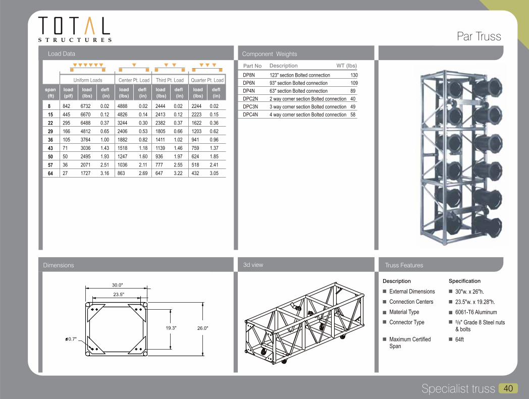
S T R U C T U R E S
Specialist truss 40
Component WeightsLoad Data
3d viewDimensions Truss Features
Part No Description
DP8N
DP6N
DP4N
DPC2N
DPC3N
DPC4N
123" section Bolted connection
93" section Bolted connection
63" section Bolted connection
2 way corner section Bolted connection
3 way corner section Bolted connection
4 way corner section Bolted connection
130
109
89
40
49
58
WT (lbs)
Uniform Loads Center Pt. Load Third Pt. Load Quarter Pt. Load
(ft) (plf) (lbs) (in)
span load defl
(lbs) (in) (lbs) (lbs)(in) (in)
load deflload deflload deflload
8
15
22
29
36
43
50
57
64
842
445
295
166
105
71
50
36
27
6732
6670
6488
4812
3764
3036
2495
2071
1727
0.02
0.12
0.37
0.65
1.00
1.43
1.93
2.51
3.16
4888
4826
3244
2406
1882
1518
1247
1036
863
0.02
0.14
0.30
0.53
0.82
1.18
1.60
2.11
2.69
2444
2413
2382
1805
1411
1139
936
777
647
0.02
0.12
0.37
0.66
1.02
1.46
1.97
2.55
3.22
2244
2223
1622
1203
941
759
624
518
432
0.02
0.15
0.36
0.62
0.96
1.37
1.85
2.41
3.05
Description Specification
External Dimensions
Connection Centers
Material Type
Connector Type
Maximum Certified Span
30"w. x 26"h.
23.5"w. x 19.28"h.
6061-T6 Aluminum
5/8" Grade 8 Steel nuts & bolts
64ft
30.0"
23.5"
19.3" 26.0"
0.7"
Par Truss
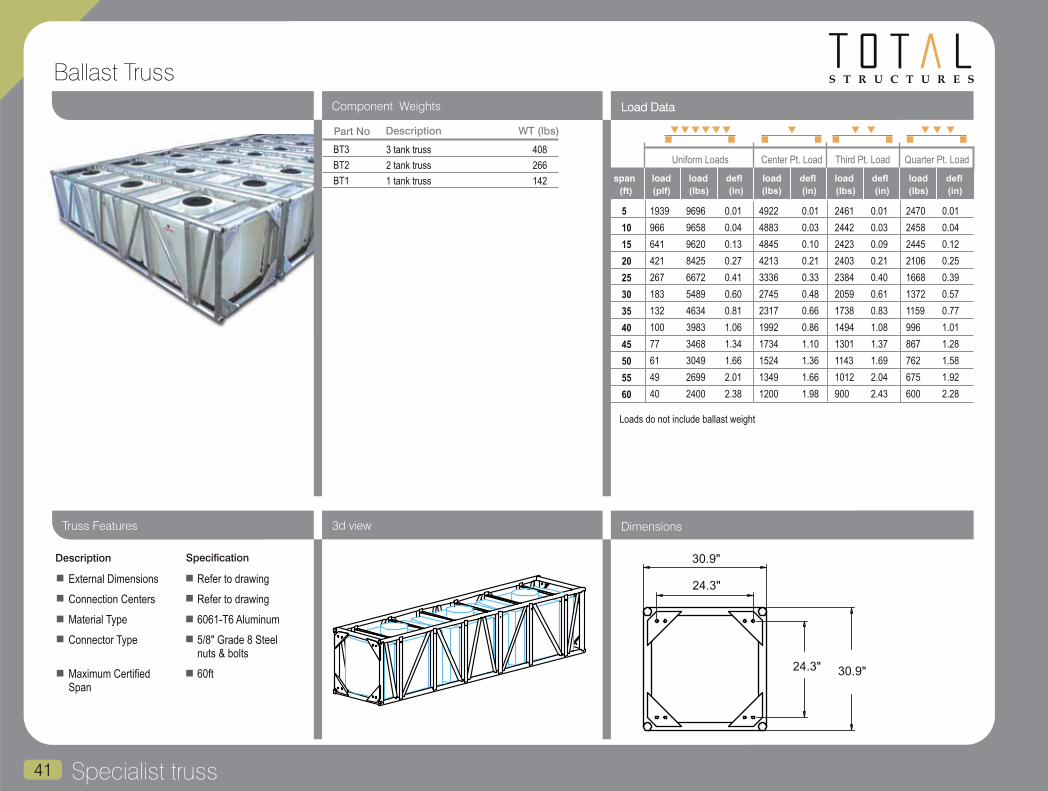
S T R U C T U R E S
Specialist truss41
Ballast Truss
Component Weights Load Data
3d view DimensionsTruss Features
Part No Description
BT3
BT2
BT1
3 tank truss
2 tank truss
1 tank truss
408
266
142
WT (lbs)
Description Specification
External Dimensions
Connection Centers
Material Type
Connector Type
Maximum Certified Span
Load Data
5
10
15
20
25
30
35
40
45
50
55
60
1939
966
641
421
267
183
132
100
77
61
49
40
9696
9658
9620
8425
6672
5489
4634
3983
3468
3049
2699
2400
0.01
0.04
0.13
0.27
0.41
0.60
0.81
1.06
1.34
1.66
2.01
2.38
4922
4883
4845
4213
3336
2745
2317
1992
1734
1524
1349
1200
0.01
0.03
0.10
0.21
0.33
0.48
0.66
0.86
1.10
1.36
1.66
1.98
2461
2442
2423
2403
2384
2059
1738
1494
1301
1143
1012
900
0.01
0.03
0.09
0.21
0.40
0.61
0.83
1.08
1.37
1.69
2.04
2.43
2470
2458
2445
2106
1668
1372
1159
996
867
762
675
600
0.01
0.04
0.12
0.25
0.39
0.57
0.77
1.01
1.28
1.58
1.92
2.28
Uniform Loads Center Pt. Load Third Pt. Load Quarter Pt. Load
(ft) (plf) (lbs) (in)
span load defl
(lbs) (in) (lbs) (lbs)(in) (in)
load deflload deflload deflload
30.9"
24.3"
30.9"24.3"
Refer to drawing
Refer to drawing
6061-T6 Aluminum
5/8" Grade 8 Steel nuts & bolts
60ft
Loads do not include ballast weight
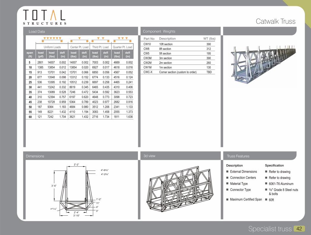
S T R U C T U R E S
Specialist truss 42
Component Weights
Uniform Loads Center Pt. Load Third Pt. Load Quarter Pt. Load
(ft) (plf) (lbs) (in)
span load defl
(lbs) (in) (lbs) (lbs)(in) (in)
Load Data
load deflload deflload deflload
3d viewDimensions Truss Features
Catwalk Truss
Part No Description
CW10
CW8
CW5
CW3M
CW2M
CW1M
CWC-X
10ft section
8ft section
5ft section
3m section
2m section
1m section
Corner section (custom to order)
390
312
195
390
260
130
TBD
WT (lbs)
5
10
15
20
25
30
35
40
45
50
55
60
2801
1385
913
677
536
441
374
310
238
187
149
121
14007
13854
13701
13548
13395
13242
13089
12394
10728
9364
8221
7242
0.002
0.012
0.042
0.098
0.192
0.332
0.528
0.757
0.959
1.183
1.432
1.704
14007
13854
13701
13312
10512
8619
7246
6197
5364
4684
4110
3621
0.002
0.020
0.066
0.152
0.239
0.345
0.472
0.620
0.789
0.980
1.194
1.432
7003
6927
6850
6774
6697
6465
5434
4648
4023
3512
3083
2716
0.002
0.017
0.056
0.133
0.258
0.435
0.592
0.773
0.977
1.206
1.458
1.734
4669
4618
4567
4516
4465
4310
3623
3098
2682
2341
2055
1811
0.002
0.016
0.052
0.124
0.241
0.406
0.553
0.723
0.916
1.133
1.373
1.636
Description Specification
External Dimensions
Connection Centers
Material Type
Connector Type
Refer to drawing
Refer to drawing
6061-T6 Aluminum
5/8" Grade 8 Steel nuts & bolts
60ft
0”
3”-6”
2”-2”
54”-6 /8”
54”-2 /8”
1”-2”
11”
4”
2”-4”
3”-10”
11Ø /16”
Maximum Certified Span
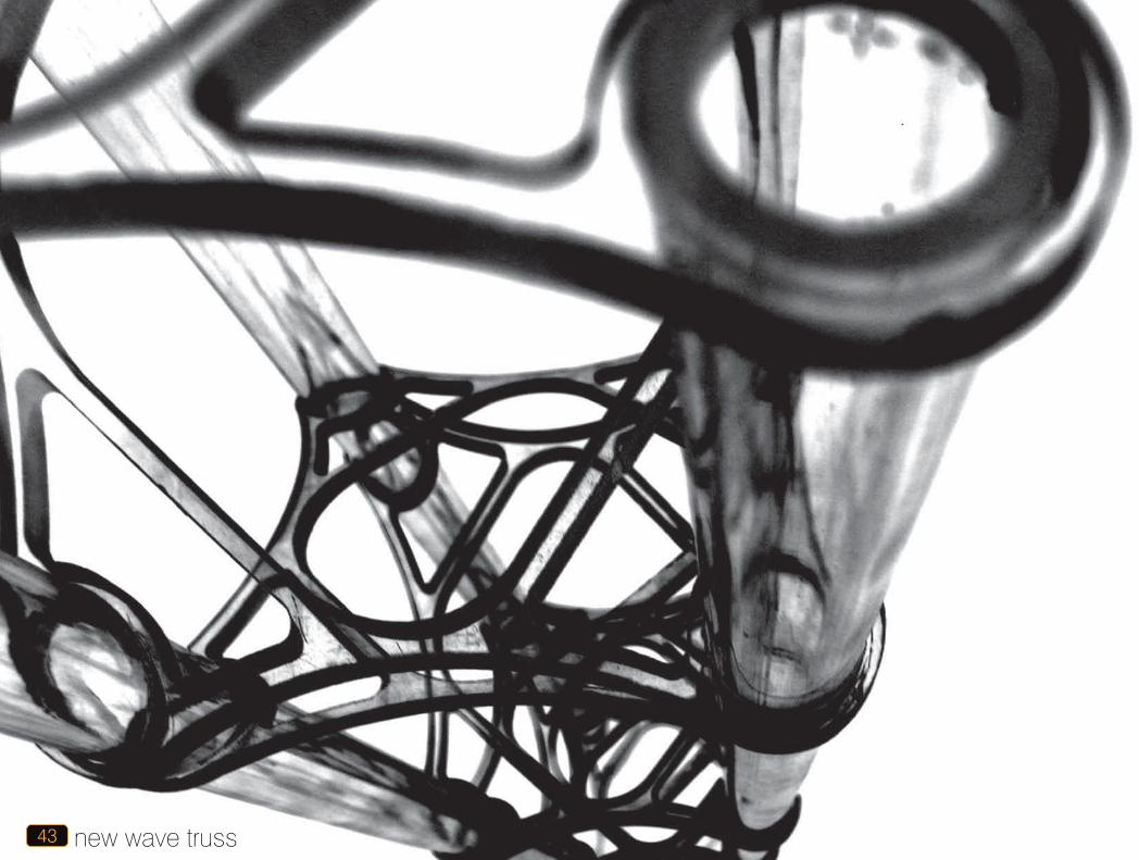
new wave truss43

That it is a truss is where the conventional thinking ends with new wave. It is the result of three years of ideas and concepts coming together to create a single, very special, product. The four most important of these ideas are construction, materials, connection and finishing.
new wave is constructed using a series of perforated plates that are bonded to the main chords that pass through them. This in turn allows a variety of materials to be used - all aluminum, Plexiglas and, most popular of all, a carbon fiber / aluminum hybrid. Added to this was a variation of LDI 2000 Award winner, the OMNI connector. The rotating fork connection allows the truss to be assembled in an almost limitless variety of two and three-dimensional structural forms without custom fabrication.
The diversity of finishes, looks and branding opportunities is staggering. For example, the carbon fiber chords can be printed with custom textures, logos or messages or finished with a variety of Kevlar fabrics. Amongst those
2000 LDI Product of the Year - Rigging and
Hardware - Omni Connector
2002 LDI Debuting Product of the Year
Rigging and Hardware - new wave truss
2002 Rental and Staging Magazine -
Product of the Year - new wave truss
2002 The Exhibitor Show Dealers Choice
Award - new wave truss
2003 PLASA Award for Product
Excellence - new wave truss
2004 The Aluminum Association
International Extrusion of the Year - new
wave extrusion
44new wave truss
available are trusses that look like they were made of wood, and a red and yellow woven fabric, amongst a dazzling display of others.
The structural web can also be formed to carry a company logo or other pattern, such as the “Vegas” truss pictured overleaf that has chords printed with playing cards and a structural web in the form of clubs, diamonds, hearts and spades. In addition, the web can be anodized prior to assembly, and therefore several colors can be accommodated within the same truss.
The “Standard” new wave product is comprised of black carbon fiber finish chords, with bright aluminum web and is available in 1ft increments up to 10ft.
New wave has its own website at www.newwavetruss.com

45 new wave truss
S T R U C T U R E S
Component Weights Load Data
3d view DimensionsTruss Features
A - Wave
Part No Description
NWA10
NWA9
NWA8
NWA7
NWA6
NWA5
NWA4
NWA3
NWA2
NWA3M
NWA2.5M
NWA2M
NWA1.5M
NWA1M
NWA0.5M
10ft Section
9ft Section
8ft Section
7ft Section
6ft Section
5ft Section
4ft Section
3ft Section
2ft Section
3m Section
2.5m Section
2m Section
1.5m Section
1m Section
0.5m Section
12
11
10
9
8
7
6
5
4
12
10
8
7
5
4
WT (lbs)
4
8
12
16
20
24
413
205
110
33
12
4
1651
1640
1315
525
237
104
0.10
0.50
1.30
1.30
1.30
1.30
1651
1129
657
262
118
52
0.10
0.50
1.00
1.00
1.10
1.10
Uniform Loads Center Pt. Load
(ft) (plf) (lbs) (in)
span load defl
(lbs) (in)
load deflload
6.2"
4.7"
4.7" 6.2"
Description Specification
External Dimensions
Connection Centers
Material Type
Connector Type
Maximum Certified
6"w. x 6"h.
5"w. x 5"h.
Aluminum (Various alloys)
new wave OMNI connectors
24ft
New wave U.S. Patent Number 7197856.
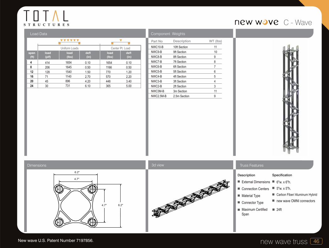
S T R U C T U R E S
46new wave truss
C - Wave
Component WeightsLoad Data
3d viewDimensions
Part No Description
NWC10-B
NWC9-B
NWC8-B
NWC7-B
NWC6-B
NWC5-B
NWC4-B
NWC3-B
NWC2-B
NWC3M-B
NWC2.5M-B
10ft Section
9ft Section
8ft Section
7ft Section
6ft Section
5ft Section
4ft Section
3ft Section
2ft Section
3m Section
2.5m Section
11
10
9
8
7
6
5
4
3
11
9
WT (lbs)
4
8
12
16
20
24
414
206
128
71
45
30
1654
1645
1540
1140
896
731
0.10
0.50
1.50
2.70
4.20
6.10
1654
1166
770
570
448
365
0.10
0.50
1.20
2.20
3.40
5.00
Uniform Loads Center Pt. Load
(ft) (plf) (lbs) (in)
span load defl
(lbs) (in)
load deflload
6.2"
4.7"
4.7" 6.2"
Description
Truss Features
Specification
External Dimensions
Connection Centers
Material Type
Connector Type
Maximum Certified
Span
6"w. x 6"h.
5"w. x 5"h.
Carbon Fiber/ Aluminum Hybrid
new wave OMNI connectors
24ft
New wave U.S. Patent Number 7197856.

S T R U C T U R E S
47 new wave truss
assembly data
assembly data
90 Degree corner with leg 90 Degree corner with leg exploded view Side attachment Side attachment exploded view
Base assembly exploded view 90 degree 4-way junction Custom angle with spreaders ”T” junction with leg
New wave U.S. Patent Number 7197856.

48new wave truss
S T R U C T U R E S design help
design help
new wave's rotating fork connection system offers an infinite number of ways to assemble a system without requiring custom fabrication. The illustrations on the opposite page show how conventional intersections are achieved, while on this page they demonstrate just a fraction of what can be done. All new wave standard lengths are available in easy to use 3D CAD blocks in both .dwg and .dxf formats on a CD. Contact us and we will be happy to send one to you. We are more than happy to help develop your ideas if you do not have the tools to do it yourself, or if you just want some guidance. Just another example of Total Structures providing...
“all the support you need”.
New wave U.S. Patent Number 7197856.

S T R U C T U R E S
Ground Support49
ground supportIntroduction to Ground Support
As with all Total Structures products, a constant
effort is made to improve or refine the ground
support series. The latest innovations include:-
Replaceable machined components Adjustable (in 1" increments) stabilizer bracesChamfered edges on components Machined stainless steel hitch pins
As with all ground support systems, load capacity
is dependent on tower height and the method of
bracing the tower. Please refer to the structural
engineers report or contact Total Structures for
further information.
Series 12 is designed for use with the entire range of Total Structures truss. It is typically used with small to medium roof and ground support configuration. Series 18 is designed for use with Total Structures truss where trusses are 26" wide or greater (Typically Wide Heavy Duty, Par truss and The Fold Flat series) Series 18 is typically used on Medium to Large sized roof and ground support systems, or where greater trim height or load capacity is required
The Total Structures Ground Support Series is available in two standard formats, Series 12 and Series 18.

Ground Support 50
S T R U C T U R E S Ground Support - Series 12
(ft) (lbs)
heightaxial
load
Load Data 12” Tower
10
15
20
25
30
35
40
45
17977
17952
17926
17901
17875
17850
13650
10717
14732
13084
11436
9788
7098
4106
2279
1102
14732
13084
11436
8542
4882
2797
1520
695
14732
13084
8764
4749
2679
1495
766
290
(lbs)
axial
load(lbs)
axial
load(lbs)
axial
load
K=1.0 K=1.25 K=1.5 K=2.0
Part No Description
GST10F
GST8F
GST5F
GST3M
GST2M
GST1M
GSTHN
HGSTPN
GSTB
GSTS
10ft. Tower Bolted Connection
8ft. Tower Bolted Connection
5ft. Tower Bolted Connection
3m Tower Bolted Connection
2m Tower Bolted Connection
1m Tower Bolted Connection
Hinge tower section Bolted Connection
Head Block
Base unit
Set of adjustable stabilizers W/braces (4 per set)
66
56
41
66
49
32
56
31
40
53
WT (lbs)
Effectively held in position at both ends, but not restrained in direction.
Effectively held in position at one end, and restrained in direction at both ends.
Effectively held in position and restrained in direction at one end, and partially restrained in direction but not held in position at the other end.
Effectively held in position and restrained in direction at one end, but not held in position or restrained at the other end.
If a point is “held in position, but not restrained in direction”, then it can be considered as “pinned”.
If a point is “held in position and restrained in direction”, then it can be considered as “fixed”.
Table 1: Factors to determine effective lengths of towers.
K = 1.0
K = 1.25
K = 1.5
K = 2.0
Truss manufactured by Total Structures Inc. is designed in accordance with the “Specifications for Aluminum Structures” by the Aluminum Association Inc.
The user should refer to “Operating manual for Modular Aluminum Truss and Tower Sections” and the “Operating manual for Demountable Aluminum Roof Top Structures” where applicable.
Component Weights
Ground Support is the industry standard means of supporting truss grids, where flying points are not available. The 12 inch tower interfaces with most types of Total Structures truss in both indoor grids and outdoor roof structures. A full set of associated parts are available and include headblocks, bases, stabilizers and hinges. Please refer to structural calculations for allowable loads for various applications.
HOIST
Top pulley section
Tower section
Sleeve section
Hinge section
Adjustable stabilizers

Ground Support51
S T R U C T U R E SGround Support - Series 18
(ft) (lbs)
heightaxial
load
Load Data 18” Tower
(lbs)
axial
load(lbs)
axial
load(lbs)
axial
load
K=1.0 K=1.25 K=1.5 K=2.0
Effectively held in position at both ends, but not restrained in direction.
Effectively held in position at one end, and restrained in direction at both ends.
Effectively held in position and restrained in direction at one end, and partially restrained in direction but not held in position at the other end.
Effectively held in position and restrained in direction at one end, but not held in position or restrained at the other end.
If a point is “held in position, but not restrained in direction”, then it can be considered as “pinned”.
If a point is “held in position and restrained in direction”, then it can be considered as “fixed”.
Table 1: Factors to determine effective lengths of towers.
K = 1.0
K = 1.25
K = 1.5
K = 2.0
10
15
20
25
30
35
40
45
50
55
60
27493
27453
27412
27372
27331
27291
27251
27210
27170
26756
22371
24391
22800
21208
19617
18025
16434
14843
12476
8812
6193
4269
24391
22800
21208
19617
18025
16434
12248
8553
5996
4165
2817
24391
22800
21208
19617
14900
9897
6748
4652
3196
2148
1373
Part No Description WT (lbs)
Component Weights
HGST10F
HGST8F
HGST5F
HGST3N
HGST2N
HGST1N
HGSTHN
HGSTPN
HGSTB
HGSTS
10ft. Tower Bolted Connection
8ft. Tower Bolted Connection
5ft. Tower Bolted Connection
3m Tower Bolted Connection
2m Tower Bolted Connection
1m Tower Bolted Connection
Hinge tower section Bolted Connection
Head Block
Base unit
Set of adjustable stabilizers W/braces (4 per set)
86
71
52
86
59
34
62
41
52
53
Top pulley section
Tower section
Sleeve section
As with the 12 inch ground support, the 18 inch tower interfaces with virtually all Total Structures truss, (where overall truss dimensions allow), and is used where higher load capacity and increased height are required. A full set of associated parts are available as for the 12 inch series. Please refer to structural calculations for allowable loads for various applications.
Adjustable stabilizers
Hinge section

S T R U C T U R E S
v towerIntroduction to V-Tower
V-Tower 52
The Total Structures V-Tower system is
designed specifically to fly line array
sound systems with the least amount of
fuss possible. It has been designed
around a triangular based pyramid
which allows the smallest practical
base area whilst cleverly enabling its
load and self weight to become its own
ballast.
We build our V-Tower system around standard tower truss sizes so that the majority of the components can be taken from existing inventory or, once purchased, have a life beyond their use in a V-Tower. “Standard” truss sizes utilized are 12”, 18” and 20 ½” although larger trusses can be utilized when the situation demands.
Generic engineering cases have been developed for a number of applications, but at Total Structures we know that
more often than not there is almost no such thing as a “standard” application so we have developed our engineering to be flexible so that a number of variables can be changed to produce a report tailored to meet each of our clients needs. Examples of these variables include tower height, truss size, local wind load code requirements, weight AND size of payload (surface area attracts wind load) as well as individual needs to use various systems with the tower. Most certainly one size does not, and should not, fit all.
Our system was designed with health and safety in mind from its conception, and there is no need to climb during its assembly or installation of its payload.

V-Tower53
S T R U C T U R E SV-Tower
v-tower

ArenA Deck 54
arena deckIntroduction to ArenA Deck
REN A DECK
Standard finish is all aluminum with a
high quality marine ply deck with
integrated non-slip embossed finish in
black. The clever interlocking design
means that no tools are required for
assembly and a standard 60ft x 40ft
deck can be assembled by 6 people in
under 2 hours.
The Standard 8ft x 4ft deck system
comprises of only 6 component types,
Deck, Leg, 8ft and 4ft Gates and 8ft
and 4ft link beams. The structure that is
created provides under stage storage
and access.
As you would expect from a Total
Structures product, accessories,
ArenA Deck is a high performance, modular staging system that has been tried and tested in
the market over a number of years. Fully engineered to perform for all but the most extreme
applications, ArenA Deck has a load capacity of 150lbs per sq/ft and can be manufactured
to higher performance specifications on request.
storage and shipping have all be given
close scrutiny. Standard accessories
include ramps, stairs, hand rails and
storage/ shipping carts. Custom dollies
are produced to order to deal with
special packing requirements.
The nature of the system also allows the
inclusion of standard components
seamlessly into a custom stage set.
Custom elements including curves,
ramps, stairs and thrusts are all
comfortably created from the systems
designed functions. Custom decks that
include curves and odd angles are all
tailored using CAD based water jet
cutting that ensure a perfect fit at final
assembly.
S T R U C T U R E S
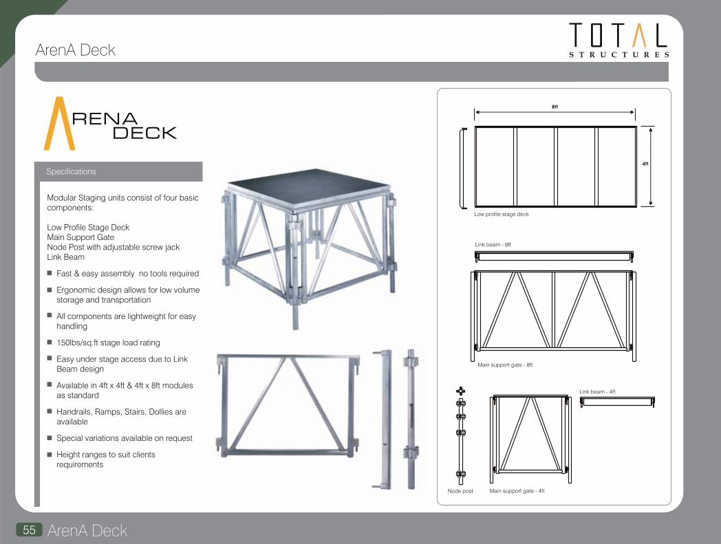
ArenA Deck55
S T R U C T U R E SArenA Deck
Modular Staging units consist of four basic components:
Low Profile Stage DeckMain Support GateNode Post with adjustable screw jackLink Beam
Fast & easy assembly no tools required
Ergonomic design allows for low volume storage and transportation
All components are lightweight for easy handling
150lbs/sq.ft stage load rating
Easy under stage access due to Link Beam design
Available in 4ft x 4ft & 4ft x 8ft modules as standard
Handrails, Ramps, Stairs, Dollies are available
Special variations available on request
Height ranges to suit clients requirements
8ft
4ft
Low profile stage deck
Link beam - 8ft
Link beam - 4ft
Node post Main support gate - 4ft
Main support gate - 8ft
REN A DECK
Specifications

ArenA Deck 56
S T R U C T U R E S ArenA Deck
4' Gate
8' Gate
4' Link Beam
8' Link Beam
4' Railing
8' Railing
4' Node Post
Scaff Jack
4' x 8' Deck
Stairs

Chain Hoists57
S T R U C T U R E S
The Power to Perform
ET
ENTERTAINMENT TECHNOLOGY
LODESTAR
Introduction to chain hoists
S T R U C T U R E S
Total Structures is an Entertainment Master
Distributor for America's favorite chain
hoist. With on the shelf inventory, in house
technicians, competitive pricing, regular
motor schools and a sales team with over
30 years of product experience, we are
your best choice when it comes to filling
your lifting needs. In addition to hoists,
Total Structures carries several lines of
motor control, cabling, and rigging
hardware, providing you with a complete
system solution. From production houses,
resellers, and end users to architects and
specifiers, Total Structures can help you
accomplish your jobs with the best
equipment for your application.
A vast range of CM products are available
including a multitude of spares and
accessories. Featured opposite are the
specifications for the most popular hoists
used globally in the temporary structures
market, the “riggers choice” Lodestar and
the increasingly popular and renowned
baby brother, the Prostar.

Chain Hoists 58
ProstarLodestar
The CM Prostar models are designed and built for the unique rigging applications encountered at small venues. Lightweight, quiet and portable, the CM Prostar features an overload device that protects the operator and structure from damaging overloads.
Features Features
Technical data
Overview Overview
Technical data
Capacity(Tons)
Model No of Chains
LiftSpeedft/min
H.P. Headroom Housing Dim. (Inches)
H W L
Weight(Less Chain)
lbs
Chain Weight
(lbs per ft)
OperatingVoltage
Full LoadAmps
Capacity(lbs)
ProductCode
No of Chains
LiftSpeedft/min
H.P. Headroom Housing Dim. (Inches)
H W L
Weight(Less Chain)
lbs
Chain Weight
(lbs per ft)
OperatingVoltage
** Requires double chain, therefore multiply by 2 per ft of liftOther capacities and speeds available upon request.Other voltages including 415V three phase and 220V single phase units available upon request.
R
B
C
F
J
JJ
L
LL
R
RR
B
C
F
J
L
R
16
32
16
32
64
16
32
8
16
16
32
16
32
16
8
1/4
1/2
1/2
1
2
1
2
1
2
1/4
1/2
1/2
1
1
1
16 1/4
16 1/4
16 1/4
18 5/8
18 5/8
18 5/8
18 5/8
24 1/8
24 1/8
16 1/4
16 1/4
16 1/4
18 5/8
18 5/8
24 1/8
6 1/8
6 1/8
6 1/8
7 5/8
7 5/8
7 5/8
7 5/8
7 5/8
7 5/8
6 1/8
6 1/8
6 1/8
7 5/8
7 5/8
7 5/8
8 3/4
8 3/4
8 3/4
12 5/8
12 5/8
12 5/8
12 5/8
12 5/8
12 5/8
8 3/4
8 3/4
8 3/4
12 5/8
12 5/8
12 5/8
20 3/4
20 3/4
20 3/4
23
23
23
23
23
23
20 3/4
20 3/4
20 3/4
23
23
23
63
68
68
110
114
110
114
119
123
63
68
68
110
110
114
230/460-3-60
230/460-3-60
230/460-3-60
230/460-3-60
230/460-3-60
230/460-3-60
230/460-3-60
230/460-3-60
230/460-3-60
115-1-60
115-1-60
115-1-60
115-1-60
115-1-60
115-1-60
1.8/1.1
1.7/1.2
1.7/1.2
3.8/2.3
11.3/6
3.8/2.3
11.3/6
3.8/2.3
11.3/6
5.2
8
8
13
13
13
0.85
0.85
0.85
1.1
1.1
1.1
1.1
1.1**
1.1**
0.85
0.85
0.85
1.1
1.1
1.1**
** Requires double chain, therefore multiply by 2 per ft of liftOther capacities up to 3 Tons and other speeds available upon request.Other voltages including 220V single phase and 575V three phase available upon request.
300
300
500
600
1000
300
500
600
2042S
2074E
2127S
2045S
2129S
2049S
2018S
2048
1
1
1
2
2
1
1
2
16
40
16
8
8
16
12
8
1/6
1/6
1/4
1/6
1/6
1/6
1/6
1/6
11 5/8
11 5/8
11 5/8
11 5/8
11 5/8
11 5/8
11 5/8
11 5/8
4
4
4
4
4
4
4
4
6
6
6
6
6
6
6
6
12 1/2
12 1/2
12 1/2
12 1/2
12 1/2
12 1/2
12 1/2
12 1/2
28.6
28.6
28.6
33
33
28.6
28.6
33
0.24
0.24
0.24
0.24**
0.24**
0.24
0.24
0.24**
230-3-60
230-3-60
230-3-60
230-3-60
230-3-60
115-1-60
115-1-60
115-1-60
1.2
1.2
1.6
1.2
1.2
3.6
3.6
3.6
Full LoadAmps
Capacities – 300 to 1000lbs.Speeds – 8 – 40 ft per minuteLift – 60ft standard. Any other on requestVoltages – Three Phase 220V 60 Hz as standard with other three phase and single phase voltages available.Low voltage control – 110V for long cable runs without voltage drop. 24V and 48V optional. Direct control units also available.Compact design.Light weight. 500 Lb body weighs less than 29 lbs.Quiet and smooth.Chain stop – Mounted on chain prevents over-travel.Overload protection – Helps prevent lifting of dangerous overloads.
1/4
1/4
1/2
1/2
1/2
1
1
2
2
1/4
1/4
1/2
1/2
1
2
1
1
1
1
1
1
1
2
2
1
1
1
1
1
2
The CM Lodestar is the most durable chain hoist on the market today. Its reliability is unsurpassed in the entertainment industry.
Capacities – ¼ to 2 tons – Higher capacities available if required.Speeds – 8 – 64 ft per minute.Lift – 60ft standard. Any other on request.Voltages – Three Phase 415V/220V 50/60 Hz as standard with other three phase and single phase units available.Low voltage control – 110V for long cable runs without voltage drop. 24V and 48V optional. Direct control units also available.Voltage Board – Quick change plugs prevent improper voltage connections that can cause damage to the hoist. If misconnected, hoist will not operate. No other component changes required.Electrical – Finger safe wiring meets all electrical codes.Adjustable limit switch – Prevents loads from over travel.New 5 pocket lift wheel for improved chain wear and smooth lifting.Double brake – Optional double brake available.Load chain – Zinc plated load chain protects against corrosion. Optional black finish available.Optional CM Alloy Latchlok Hooks – Locking Hooks released only by operator.Black Powdercoat finish – For low visibility and durability.Overload protection – Helps prevent lifting of dangerous overloads.Lodestar is the “riggers choice”.

59
Chain Hoists - Columbus McKinnon
We’ve received the best reviews, heard “Bravo” countless times and, like all the greats, we’re recognized in every venue around the world. So how do we make the legendary Lodestar electric chain hoist even better? By incorporating new features that provide steady operation for any application in the entertainment industry. From today’s top-selling musical performers to international sporting competitions, organizers rely on the Lodestar for consistent performance event after event. Professional riggers have trusted the Lodestar for unsurpassed reliability for decades, and now you can experience the quietest, smoothest-running Lodestar ever. What an Encore!
The Rigger’s Choice
New features on this next
generation of Lodestar
5 pocket liftwheel
Improved chain wear & smooth lifting.
Clutch outside gear train meets international standards.
Precision helical gearing for quieter operation.
Redesigned control panel for easier access & fuse installation.
S T R U C T U R E S
BRAKE - Heavy Duty AC Brake proven design in more than 1 million Lodestars.(Double DC Brake available)
LIFT WHEEL
5 Pocket Liftwheel increases chain and liftwheel engagement while providingsmoother lifting, less vibration and reduced chain wear when properly maintained.
CONTROL PANEL
Provides easy access to controls, plug & play connectors allow for quick voltage change for dualvoltage motors. Fuses locatedon terminal strip (optional).
LOAD CHAINSizes available from 1/4 in. to 5/16 in. Meets or exceeds many national and internationalstandards. Zinc plated supplied as standard. Black phosphate finish available.100% proof tested.
CLUTCH
Designed to prevent lifting of excessive overloads. Located outside the gear box.Adjustable and easy to access.
Chain Hoists Chain Hoists 60
S T R U C T U R E S
DOUBLE BRAKE
Two independent acting DC brakes for
redundant braking. Field installation kit
available.
ENCODERS AVAILABLE
Incremental & Absolute.
CHAIN BAGS
Cloth type bags easy-to-mount.
VARIABLE SPEED UNITS AVAILABLE
ALLOY LATCHLOK HOOKS
Remains locked until
released by the operator,
even if chain goes slack.
Optional features
OVERLOAD PROTECTOR
Designed to prevent lifting of excessive
overloads. Helps prevent lifting of
dangerous overloads.
METRIC RATED MEETS REQUIREMENTS
Meets or exceeds world standards.
ROAD READY
Easy to stow and travel.
LIFETIME WARRANTY
The industry’s best.
AC ELECTROMECHANICAL BRAKE
Field tested and proven in over 1 million
lodestars worldwide.
LOW VOLTAGE CONTROL
110 volt for long cable runs without
Voltage drop 24 & 48 volt optional.
(low voltage unit only).
DURABLE & LIGHTWEIGHT HOUSING
Cast aluminum. Black powder coated
finish for low visibility.
GEARING
Helical design for long wear life and
smooth operation.
LOAD CHAIN
Designed and manufactured by Columbus
McKinnon. Zinc plated to protect against
corrosion. Optional black finish available.
DUTY CYCLE
H-4 duty rated for heavy duty application.
2m fem class. 50% duty cycle or 300
on/off per hour. Direct control units
available.
ELECTRICAL
Finger safe wiring meets all electrical
codes. Quick change plugs allow for
voltages 208 thru 460. Prevents improper
voltage connections which can cause
hoist damage. (Low Voltage Unit Only).
ADJUSTABLE LIMIT SWITCH
Adjustable screw limit switch that will
automatically stop the hook at any
predetermined point when either lifting or
lowering, preventing overtravel.
(Low Voltage Unit Only).
Standard featuresLIMIT SWITCH
Adjustable screw limitswitch that will automaticallystop the hook at anypredetermined point wheneither hoisting or lifting.
INTERNAL CHAIN GUIDEStamped Steel guide coated for corrosion resistance and quiet operation, while keeping the load chain and liftwheel aligned.
Chain Hoists

Motor Control61
S T R U C T U R E SMotor Control
An industry leader for over 20 years, Motion Laboratories has set the mark for the highest quality modular motor control and power distribution equipment. Their line of conventional style motor controllers is second to none. Whether you are looking for portable control for your touring system, or a permanent controller for a venue, Motion Labs has the right equipment for the job. All Motion Labs products conform to ETL and cETL standards for control and power distribution equipment.
Adding more flexibility to these control systems are the Server computer control and the Cell*Mate data monitoring systems. Both of these products can be used in conjunction with any Motion Labs control system to offer more precise control and monitoring of system activity.
Convenient answer to the question “How much does it weigh?” The Cell-Mate couples it's two ton rated load cells with an eight channel display unit, allowing the user to monitor point loads from the show floor, instead of walking trusses to read displays. As with all Motion Labs systems, the displays are rack mountable for ease of use and flexibility of system layout. Load cells are also available in a 5 Ton version.
Portable Motor Control Systems
Offering two styles of control systems to fit your needs, Motion Laboratories produces a system that is right for you.
MotoPac motor control
Conventional Portable Motor Control:
Permanent Installation Control Systems
Motion Laboratories offers a full range of control and power distribution systems designed for permanent installation in your facility. Available from four channel and up, with a variety of options, systems can be tailored to your specific project.
MaxPac
The latest offering in their lineup, the MotoPac is an eight channel motor controller designed with larger systems in mind. The rack mountable units can easily be chained together to operate systems as large as 32 channels.
With the optional MaxPac power distribution unit, the customer can tailor the control system to each project.
Based on a modular panel design, these controllers are available in configurations from four channels up to 32 channels. Units are available with a variety of output configurations, as well as power input connectors. Multiple controllers can be linked together via larger control pendants to allow the simultaneous operation of larger motor systems.
The computerized Server control system works with standard manual controllers, adding more precise position control and repeatability in moves during a show. Available in eight channel modules, the units can be networked together to run up to 128 hoists simultaneously.
The Server
Cell*Mate

Rigging Accessories 62
Motor Control
A full range of accessories is available to complement the Total Structures range of products. These include Road Cases, Cables, Rigging Hardware, Fixture Clamps, Fabrics and Roof Skins etc. Please contact us with your specific needs and we will be pleased to help. +1 805 676 3322 or by e-mail at [email protected].
Skjonberg Controls reputation as an innovator in the design and manufacture of rigging control systems was established in the early 1980's. Since that time they have expanded their range of equipment and services to encompass manual and programmable control of chain motors and servo control systems as well as UL listed power distribution, load monitoring, cabling and wire rope winches.
Total Structures is a distributor of Skjonberg control systems and is uniquely placed geographically for the smooth integration of equipment between the two companies.
This page provides only the smallest sample of the standard range of Skjonberg products. More information about the entire product line is available on request.
skjonbergcontrols, inc. The CS-800 is the most economical member of the modular line of controllers. Ready to run
eight individual hoists, both power distribution and relay control for the hoists reside in the same compact unit. Manual control is provided through a remote pendant with a 25 foot cable. The remote has up/down select switches and LED indicators for each hoist, momentary run button, and an emergency stop switch that controls a disconnect contactor. Not only is the CS-800 a stand alone unit, it can also be used with the line of controls. Add four CS-800’s to the TR-3200 Manual Control to run 32 hoists under computer control. CS-400, 4 way controller is also available.
The TR Series offers 32 channels of relay and the manual control plus power distribution packaged in a convenient road case. The case houses the TR-3200, four TR-8000s and the TR-200. It is available in all international voltages using either Cee form or Hubbell connectors.
TR manual control series
CS-800
Rigging Accessories

S T R U C T U R E S
RSC Lightlock63
motion dampening for moving lights
The RSC Lightlock (Pat pending) is a revolutionary new device for the entertainment industry, which allows moving lights to be rigged on very lightweight hanging or flown, structures. Until now it has been impossible to hang moving lights onto trapezes, lightweight automated bars or pantographs due to unwanted oscillation in the structure. The RSC Lightlock is the first device of its kind to counteract and eliminate unwanted movement of automated lights on lightweight structures and opens up a plethora of lighting solutions.
RSC Lightlock is the proud winner of the following awards….
PLASA
Gold Award for Innovation
LDI
Best Debuting Product Award
Live Design Magazine
Product of the Year
2008
2009
2010
Pat Pending

RSC Lightlock 64
When the Royal Shakespeare Company began planning the £112 million ($200million) refurbishment its Head of Lighting, Vince Herbert, saw a unique opportunity to transform the way that theatre lighting rigs were assembled. Here Vince talks about how necessity brought about the invention of the RSC Lightlock.
“I started working on this concept when we were working on the refurbishment of the Royal Exchange Theatre in Manchester several years ago. The idea was to put moving lights onto television pantographs so that we could vary the angle of the lighting within cues and make them much easier to maintain.
“When we started talking about the RSC's auditorium designs for the new Royal Shakespeare Theatre in Stratford-upon-Avon, Flip Tanner (the Technical Project Co-coordinator) asked me what I really wanted the rig to look like and what we should do with it. I had never forgotten the modular cluster lighting idea, and this was the ideal time to put it into place. It was
The RSC Lightlock Story
Lightlock inventor Vince Herbert pictured with Patrick Stewart at The Courtyard Theatre in Stratford-upon-Avon
As You Like It Photos by Ellie Kurttz
As You Like It Photos by Ellie Kurttz
Julius Caesar Photos by Ellie Kurttz
Julius Caesar Photos by Ellie Kurttz
The Winter's Tale Photos by Alessandro Evangelista
also driven by health and safety because in the future we won't be climbing up to the lights; the lights will be coming down to us.
“However there is a huge drawback with a small modular single or cluster moving light hang: they swing! I did an experiment in The Courtyard Theatre to test just how much it would swing and it was way more than expected. I realized at this point that I would need to find or design something that would stop the swing. I assumed that this problem must have already been solved, and when I found it hadn't I realized that it was up to me! In the name of research I spent some time on a swing in a park in Stratford-upon-Avon. The idea I had was that if you could start yourself swinging by moving your legs, you could stop yourself by moving your legs in the other direction. I must have looked crazy testing out my theory. However, it worked! An equal and opposite amount of energy: simple physics.”
From this point Vince developed the RSC Lightlock device. The prototype was exhibited publicly for the first time at PLASA
08, winning a Gold Award for Innovation and attracting interest from a number of manufacturers as well as designers and end users. The contract to develop, manufacture and sell Lightlock was eventually awarded to Total Solutions Group and U.S. strategic partner Total Structures Inc. on the grounds of experience, geography and not least of all both companies commitment to innovation and safety.
Pat Pending

65 RSC Lightlock
The main benefits of the RSC's lighting invention are:
CreativityThe device enables the creative benefits of moving lights to be used in a broader variety of theatre, TV and film situations as it removes the need for heavy duty mounting infrastructure.
FlexibilityUse of lightweight rigging means that the moving light can be situated virtually anywhere and the halting of movement ensures that there are no 'out of action' moving lights.
Quiet OperationThe RSC Lightlock emits low noise levels, which allows its use during live performances.
Health and SafetyThe RSC Lightlock reduces the need for bridges or trusses and therefore reduces the need for working at height when maintaining or adjusting a light.
Cost efficiencyMoving lights can be maintained at ground level by lowering the rig to where staff can safely maintain or adjust them. Avoiding working at height results in significant time savings for the entertainment industry.
EnvironmentalA lighting designer can choose to create the same design with a smaller rig, resulting in a cost saving and environmental benefit.
RSC Lightlock,
S T R U C T U R E S
Benefits and FAQs
How does it work?
Will the RSC Lightlock stabilize a truss or pipe when one or more automated fixtures are moving?
How many moving fixtures can be moving in unison before one RSC Lightlock becomes ineffective?
The RSC Lightlock works by accelerating and decelerating a balanced mass or weight at the appropriate moment of the swing cycle of a moving structure.
Yes.
The RSC Lightlock will remain effective for as many moving fixtures as you require, however it will take slightly longer for the structure to come to rest, so instead of stopping the swing instantly it may take a second or two.
Will RSC Lightlock correct oscillations produced by wind?
Is RSC Lightlock affected by heat emitting from moving fixtures?
Does it need data?
Does it need a secondary safety device?
Does it require any specialist rigging?
Can I tour RSC Lightlock's into different countries with different voltages?
Does it require calibration?
What power does it use?
Do you need a different size RSC Lightlock for larger or smaller items?
How do I rig the RSC Lightlock?
No, not at the moment - in its current design the RSC Lightlock will only correct oscillations produced by something that is attached to the structure. That is to say, the RSC Lightlock cannot dampen movement caused by an external force pushing the structure. However watch this space as developments are on going….
No.
No.
As with all devices rigged at height, the RSC Lightlock requires a safety bond. The RSC Lightlock also has an added internal electronic safety device that prevents it from being rigged the wrong way up.
No.
Yes, the power supply unit is self switching.
The RSC Lightlock self-calibrates every time you power-up; this usually takes about 1.5 seconds.
The RSC Lightlock runs at a maximum of 150 watts.
No, the standard RSC Lightlock will serve most applications, but for larger items RSC Lightlocks can be added together to work in unison with each other.
The RSC Lightlock has an integrated track for ½” or M12 fixings that can be rigged with standard clamps and couplers or direct mount plates.
FAQs
What people say about RSC Lightlock
I've worked as a Lighting Designer for many years lighting shows for the RSC and other leading theatre companies. I've always been frustrated by the limitations of traditional lighting solutions and am delighted that the RSC has designed this revolutionary new product which will open up more flexible creative choices.
,,
,,
Tim Mitchell, Lighting Designer for the RSC's 2008
production of Hamlet.
New things are invented for theatre lighting all the time usually big, expensive, technology-driven devices. But it's the simple things that make you wonder, 'Why didn't I think of that?' Lightlock is one of those inventions. On many of my shows there are flying light ladders, and no matter how you hang them two, three or four points or how hard the electricians work, the lights always end up swinging. Lightlock has solved this problem. By putting it on top of the light ladder, it keeps the ladder nice and steady while flying in and out, and prevents the audience from thinking that the show has an earthquake effect every time the scenery changes.
Lightlock is the most revolutionary product to arrive in a long time. This is an amazing compact technology that solves an age-old problem within our industry. Among other applications, I am absolutely psyched to have the ability of letting moving lights share video projection trusses with far more stability.
Lighting Designer Ken Billington
Lighting Designer Patrick Dierson
,
,
,
,
,,
,,
Pat Pending

S T R U C T U R E S
DimensionsFAQsDimensions
Technical Details
1'-8 3/8"(517.5mm) overall
1'-5"(431.8mm) slot centres
1'-5 1/2"(444.5mm) overall
3"(76.2mm) overall
The unit measures approximately 1'-8 3/8" (517.5mm) wide x 1'-5 1/2" (444.5mm) deep x 3" (76.2mm) high.
The RSC Lightlock draws a maximum
of 150 watts.
RSC Lightlock weighs 31lb (14kg).
E
I
H
F
G
Accessories
A
D
C
B
Sample Applications
A
B
C
D
E
F
G
H
I
LL-R-01
LL-P-01
LL-A-01
LL-R-02
LL-R-03
LL-F-01
LL-P-002
LL-P-02
LL-R-04
2-way Bridle (pair)
Powercon input cable to bare tail (a range of connectors can be added to suit clients location and preference)
Universal moving light adaptor w/hardware
Bridle bracket (pair)
Eyebolt and hardward
Hanging clamp
Powercon "A" to "B" cable
Half coupler
Stacking adaptor
Pat Pending RSC Lightlock 66

S T R U C T U R E S
USA Office
European Office
Tel: (805) 676 3322
Fax: (805) 676 1616
E-mail: [email protected]
Web: www.totalstructures.com
Tel: +44 (0) 7771 661348
Fax: +44 (0) 1684 311893
E-mail: [email protected]
Total Structures Inc.
1696 Walter Street, Ventura, CA 93003, USA
Recommended