Combination Starters
Class 8538/8539, 8738/8739
CONTENTS
Description . . . . . . . . . . . . . . . . . . . . . . . . . . . . . . . . . . . . . . . . . . . . . . . . . . . . . . . . . Page
General Information . . . . . . . . . . . . . . . . . . . . . . . . . . . . . . . . . . . . . . . . . . . . . . . . . . . . . . 2Combination Starters — NEMA Rated . . . . . . . . . . . . . . . . . . . . . . . . . . . . . . . . . . . . . . . 3
Application Data . . . . . . . . . . . . . . . . . . . . . . . . . . . . . . . . . . . . . . . . . . . . . . . . . . . . . . 12Approximate Dimensions and Shipping Weights. . . . . . . . . . . . . . . . . . . . . . . . . . . . . 17Panel Layout Drawings . . . . . . . . . . . . . . . . . . . . . . . . . . . . . . . . . . . . . . . . . . . . . . . . . 20Reversing Combination Starters — NEMA Rated. . . . . . . . . . . . . . . . . . . . . . . . . . . . 21Application Data . . . . . . . . . . . . . . . . . . . . . . . . . . . . . . . . . . . . . . . . . . . . . . . . . . . . . . 27Approximate Dimensions . . . . . . . . . . . . . . . . . . . . . . . . . . . . . . . . . . . . . . . . . . . . . . . 28
Panel Layout Drawings . . . . . . . . . . . . . . . . . . . . . . . . . . . . . . . . . . . . . . . . . . . . . . . . . . . 29Factory Modifications . . . . . . . . . . . . . . . . . . . . . . . . . . . . . . . . . . . . . . . . . . . . . . . . . . . . 30Replacement Parts Kits . . . . . . . . . . . . . . . . . . . . . . . . . . . . . . . . . . . . . . . . . . . . . . . . . . 38Coils and Accessories . . . . . . . . . . . . . . . . . . . . . . . . . . . . .Refer to Catalog 9999CT9701

© 1998 Square D All Rights Reserved
2
1/98
Class 8538 and 8539 Type S combination starters combine the requirements of motor overload and short circuit protection into one package. These starters are manufactured in accordance with NEMA standards and are UL Listed (although some FORM numbers may not be listed – contact your local Square D representative for information). Class 8538 and 8539 combination starters are designed to operate at 600 Vac maximum, 50 to 60 Hz – and are supplied with melting alloy overload relays as standard.
Type 2 Coordination
Square D is one of the leaders in North America and Europe in providing starters that are verified by UL to comply with IEC 947-4-1 and Type 2 coordination. This means that the components of a motor branch circuit protective device (fuses and circuit breaker), contactor, and overload relay will be suitable for further use following a short circuit fault (even though contact welding is recognized but can be easily broken) allowing for replacement of components druing normal scheduled maintenance.
Square D starters and specified fuses have been tested by UL and CSA (at 100,000 Amps fault current) for operation at 600 volts AC. Class 8538 Type S Combination Starters, NEMA size 0 through 5, with fusible disconnect switches have tested to Type 2 performance criteria.
Class 8538 Disconnect Switch Type
Class 8538 combination starters can be supplied with either a fusible or non-fusible disconnect switch. Class 8538 combination starters are available in NEMA Sizes 0-6.
The fusible disconnect switch type combination starter design utilizes a flange operated visible blade switch. Interchangeable fuse clips, straight through wiring, space for a fused control transformer with additional capacity, and provisions for adding a disconnect switch electrical interlock are key features of the combination starters.
The fusible disconnect switch type can be supplied with Class R fuse clips increasing the short-circuit rating to 100,000A.
Size 0-2 non-fusible combination starters can be converted to a fusible type. See Catalog 999CT9701 for fuse block kits and fuse clips.
Class 8539 MAG-GARD
®
Motor Circuit Protector orThermal Magnetic Circuit Breaker
Class 8539 combination starters can be supplied with either a MAG-GARD
®
motor circuit protector (MCP) or a thermal magnetic circuit breaker. Class 8539 combination starters are available in NEMA Sizes 0-7.
The circuit breakers in Class 8539 combination starters can be supplied with a factory installed auxiliary switch for remote indication of an open and/or tripped or closed breaker. For one auxiliary switch, specify
Form Y74
. For two auxiliary switches, specify
Form Y75
. The switches are supplied with normally open and normally closed circuits with a common connection. Contacts must be used on the same polarity and are rated 15 Amps at 240 Volts AC.
An alarm switch can be factory supplied only, specify
Form Y742.
The alarm switch only operates when the breaker is tripped. It is used to actuate bell alarms and warning lights. The alarm switch consists of a normally open single pole single throw switch. The contacts are rated 4 Amps at 240 Volts AC.
General Information
Enclosures
– Class 8538 and 8539 combination starters are available in the following enclosures:
NEMA Type 1 General Purpose NEMA Type 4 & 4X Watertight and Dusttight Stainless SteelNEMA Type 4X Watertight, Dusttight, and Corrosion Resistant Glass-PolyesterNEMA Type 7 & 9 Bolted and Spin-Top
®
for Hazardous Locations (Class 8539 only).NEMA Type 12 Dusttight and Driptight for Industrial Use
The NEMA Type 4 & 4X stainless steel enclosure (Sizes 0 - 5) has a brushed finish. Sizes 6 & 7 are painted sheet steel enclosures and are rated NEMA Type 4 only. For an electropolished finish, specify
Form G16
and add 15% to the price of the standard device. Hubs are supplied as standard on NEMA Type 4 & 4X enclosures.
Hubs are supplied as standard on NEMA Type 4X enclosures.
NEMA Type 12 enclosures may be field modified for outdoor applications. Specify
Form G26
for NEMA Type 3R (no additional charge). See Catalog 9999CT9701 for additional information. Also, NEMA Type 12 devices are available UL Listed for use in Class II, Division 2, Group G and Class III, Divisions 1 and 2 locations. Request
Form G21
(no additional charge).
Oversized Enclosures
– Class 8538 disconnect switch type and Class 8539 MAG-GARD
®
MCP (Sizes 0-2) are available in NEMA Type 1, 4 & 4X and 12 enclosures. The oversized enclosures provide additional panel
space for customer installation of control transformers, fuse blocks, terminal blocks, relays, and other auxiliary equipment. These enclosures have three Class 9001 Type “K” holes as standard for installation of push buttons, pilot lights, and other cover mounted control units.
Coil Voltages
– AC coils are available for application on 50-60 Hz. NEMA Sizes 00 - 5 are supplied with coils that are designed to operate satisfactorily on line voltages of 85% - 110% of rated voltage. NEMA Size 6 and 7 contactors are supplied with a DC coil operated by a solid state rectifier circuit that is powered by an AC source and is designed to operate satisfactorily on line voltages of 90-110% of rated voltage.
Please note that Voltage Codes have been added to the Type designations in order to improve customer service. It is necessary to include the Voltage Code when ordering combination starters. Also, 120 Volt polyphase combination starters will be wired for separate control.
Auxiliary Contacts
– Additional auxiliary contacts may be added to Type S starters. Refer to Page 14 for maximum number of auxiliary units and Form designations for factory installed auxiliary contacts. See Catalog 9999CT9701 for auxiliary contact kits for field installation.
Type S Accessories
– Additional accessories such as fuse blocks, fuse clip kits, disconnect switch and circuit breaker interlocks, and cover mounted control stations are available for field modifications, see Catalog 9999CT9701. For factory modifications (Forms), see Pages 30-34.

1/98
Combination Starters – NEMA Rated
Class 8538 – Fusible Disconnect Switch Type
3-POLE POLYPHASE - 600 VOLTS AC MAXIMUM - 50-60 HERTZ
Devices require 3 thermal units. See catalog 9065CT9701 for selection information. For Class J fuse clip, use Form Y91 (no additional charge).
Fusible Full Voltage Type, with Melting Alloy Overload Relays
NOTE: Some control transformers may require the use of oversized enclosures. Refer to control transformer selection table on Page 35.
Fusible Disconnect Switch Type (Class H Fuse Clips), Single Phase
RatingsFuseClipSizeAmps
NEMA Type 1General PurposeEnclosure
NEMA Type 4 & 4XWatertight and Dusttight Enclosure Stainless Steel (304) (Sizes 0-5)u
NEMA Type 4XWatertight,Dusttight andCorrosion Resistant Polyester Enclosure
NEMA Type 12/3RqDusttight and DriptightIndustrial Use Enclosure
MotorVoltage(StarterVoltage)
Max.HPPoly-phase
CoilVoltaget
NEMASize
With ExternalReset
Without External Reset
Type Type Type Type Type
200(208)
3
208-60
0 30 SBG12V08 SBW12V08 SBW22V08 SBA22V08 SBA12V085
130 SCG12V08 SCW12V08 SCW22V08 SCA22V08 SCA12V08
71⁄2 60 SCG13V08 SCW13V08 SCW23V08 SCA23V08 SCA13V0810 2 60 SDG12V08 SDW12V08 SDW22V08 SDA22V08 SDA12V0820
3100 SEG15V08 SEW15V08 SEW25V08 SEA25V08 SEA15V08
25 200 SEG12V08 SEW12V08 ..... SEA22V08 SEA12V0840 4 200 SFG15V08 SFW15V08 ..... SFA25V08 SFA15V0875 5 400 SGG15V08 SGW15V08 ..... SGA25V08 SGA15V08
150 6 600 SHG13V08 SHW13V08 .... SHA23V08 SHA13V08
230(240)
3
240-60220-50
0 30 SBG12V03 SBW12V03 SBW22V03 SBA22V03 SBA12V035
130 SCG12V03 SCW12V03 SCW22V03 SCA22V03 SCA12V03
71⁄2 60 SCG13V03 SCW13V03 SCW23V03 SCA23V03 SCA13V0315 2 60 SDG12V03 SDW12V03 SDW22V03 SDA22V03 SDA12V0325
3100 SEG15V03 SEW15V03 SEW25V03 SEA25V03 SEA15V03
30 200 SEG12V03 SEW12V03 ..... SEA22V03 SEA12V0350 4 200 SFG15V03 SFW15V03 ..... SFA25V03 SFA15V03
100 5 400 SGG15V03 SGW15V03 ..... SGA25V03 SGA15V03200 6 600 SHG13V03 SHW13V03 ..... SHA23V03 SHA13V03
460(480)
5
480-60440-50
0 30 SBG13V06 SBW13V06 SBW23V06 SBA23V06 SBA13V0610 1 30 SCG14V06 SCW14V06 SCW24V06 SCA24V06 SCA14V0615
230 SDG16V06 SDW16V06 SDW26V06 SDA26V06 SDA16V06
25 60 SDG14V06 SDW14V06 SDW24V06 SDA24V06 SDA14V0650 3 100 SEG13V06 SEW13V06 SEW23V06 SEA23V06 SEA13V06
100 4 200 SFG13V06 SFW13V06 ..... SFA23V06 SFA13V06200 5 400 SGG13V06 SGW13V06 ..... SGA23V06 SGA13V06400 6 600 SHG12V06 SHW12V06 .... SHA22V06 SHA12V06
575(600)
5
600-60550-50
0 30 SBG13V07 SBW13V07 SBW23V07 SBA23V07 SBA13V0710 1 30 SCG14V07 SCW14V07 SCW24V07 SCA24V07 SCA14V0715
230 SDG16V07 SDW16V07 SDW26V07 SDA26V07 SDA16V07
25 60 SDG14V07 SDW14V07 SDW24V07 SDA24V07 SDA14V0750 3 100 SEG13V07 SEW13V07 SEW23V07 SEA23V07 SEA13V07
100 4 200 SFG13V07 SFW13V07 ..... SFA23V07 SFA13V07200 5 400 SGG13V07 SGW13V07 ..... SGA23V07 SGA13V07400 6 600 SHG12V07 SHW12V07 .... SHA22V07 SHA12V07
t Coil voltage code must be specified to order this product. Refer to standard coil voltage codes listed in selection table above or additional standard voltage codes shown on Page 4.
q NEMA Type 12 enclosures may be field modified for outdoor non-corrosive and non-service-entrance-rated applications; see Page 17 for more information.
MotorVoltage
Max.HP
CoilVoltage
NEMASize
Fuse Clips Size(Amps)
NEMA Type 1General PurposeEnclosure
NEMA Type 4 & 4XWatertightand DusttightEnclosureStainless Steel (304)
NEMA Type 4XWatertight, Dusttight and Corrosion ResistantPolyester Enclosure
NEMA Type 12/3RqDusttight and DriptightIndustrial Use Enclosure
WithExternal Reset
WithoutExternal Reset
Type Type Type Type Type
120123
120012
303060
SBG12S2V02SCG12S2V02SDG12S2V02
SBW12S2V02SCW12S2V02SDW12S2V02
SBW22S2V02SCW22S2V02SDW22S2V02
SBA22S2V02SCA22S2V02SDA22S2V02
SBA12S2V02SCA12S2V02SDA12S2V02
2302371/2
230012
303060
SBG12S2V03SCG12S2V03SDG12S2V03
SBW12S2V03SCW12S2V03SDW12S2V03
SBW22S2V03SCW22S2V03SDW22S2V03
SBA22S2V03SCA22S2V03SDA22S2V03
SBA12S2V03SCA12S2V03SDA12S2V03
q NEMA Type 12 enclosures may be field modified for outdoor non-corrosive and non-service-entrance-rated applications; see Page 17 for more information.
File E152395CCN NKJH7
File LR584Class 3211 04
File E10214CCN NOTH
Explosion proof unit
Note that not all units are or explosion proof – consult factory.
3© 1998 Square D All Rights Reserved

4
Combination Starters – NEMA Rated
Non-Fusible Disconnect Switch Type – Class 8538
3-POLE POLYPHASE – 600 VOLTS AC MAXIMUM – 50-60 HZ
Devices require 3 thermal units. See Catalog 9065CT9701 for selection information.
Non-Fusible Full Voltage Type, Non-Reversing, with Melting Alloy Overload Relays
Non-Fusible Disconnect Switch Type, Single Phase
NOTE: Some control transformers may require the use of oversized enclosures. Refer to control transformer selection table on Page 35.
Coil Voltage Codes
RatingsNEMA Type 1General PurposeEnclosure
NEMA Type 4 & 4XWatertight andDusttight EnclosureStainless Steel (304) (Sizes 0-5)f
NEMA Type 4XWatertight,Dusttight andCorrosion Resistant Polyester Enclosure
NEMA Type 12/3Rq Dusttight and Driptight IndustrialEnclosure
MotorVoltage(StarterVoltage)
Max.HPPoly-phase
CoilVoltaget
NEMASize
WithExternalReset
WithoutExternalReset
Type Type Type Type Type
200(208)
371⁄2
10254075
150
208-60
0123456
SBG11V08SCG11V08SDG11V08SEG11V08SFG11V08SGG11V08SHG11V08
SBW11V08SCW11V08SDW11V08SEW11V08SFW11V08SGW11V08SHW11V08
SBW21V08SCW21V08SDW21V08SEW21V08...............
SBA21V08SCA21V08SDA21V08SEA21V08SFA21V08SGA21V08SHA21V08
SBA11V08SCA11V08SDA11V08SEA11V08SFA11V08SGA11V08SHA11V08
230(240)
371⁄2
153050
100200
240-60220-50
0123456
SBG11V03SCG11V03SDG11V03SEG11V03SFG11V03SGG11V03SHG11V03
SBW11V03SCW11V03SDW11V03SEW11V03SFW11V03SGW11V03SHW11V03
SBW21V03SCW21V03SDW21V03SEW21V03...............
SBA21V03SCA21V03SDA21V03SEA21V03SFA21V03SGA21V03SHA21V03
SBA11V03SCA11V03SDA11V03SEA11V03SFA11V03SGA11V03SHA11V03
460(480)
5102550
100200400
480-60440-50
0123456
SBG11V06SCG11V06SDG11V06SEG11V06SFG11V06SGG11V06SHG11V06
SBW11V06SCW11V06SDW11V06SEW11V06SFW11V06SGW11V06SHW11V06
SBW21V06SCW21V06SDW21V06SEW21V06...............
SBA21V06SCA21V06SDA21V06SEA21V06SFA21V06SGA21V06SHA21V06
SBA11V06SCA11V06SDA11V06SEA11V06SFA11V06SGA11V06SHA11V06
575(600)
5102550
100200400
600-60550-50
0123456
SBG11V07SCG11V07SDG11V07SEG11V07SFG11V07SGG11V07SHG11V07
SBW11V07SCW11V07SDW11V07SEW11V07SFW11V07SGW11V07SHW11V07
SBW21V07SCW21V07SDW21V07SEW21V07...............
SBA21V07SCA21V07SDA21V07SEA21V07SFA21V07SGA21V07SHA21V07
SBA11V07SCA11V07SDA11V07SEA11V07SFA11V07SGA11V07SHA11V07
MotorVoltage
Max.HP
CoilVoltage
NEMASize
Fuse Clips Size(Amps)
NEMA Type 1General Purpose Enclosures
NEMA Type 4 & 4XWatertight and Dusttight EnclosureStainless Steel (304)
NEMA Type 4XWatertight, Dusttight and Corrosion ResistantPolyester Enclosureu
NEMA Type 12/3RqDusttight and Driptight Industrial EnclosureWithExternal Reset
WithoutExternal Reset
Type Type Type Type Type
120123
120012
N/AN/AN/A
SBG11S2V02SCG11S2V02SDG11S2V02
SBW11S2V02SCW11S2V02SDW11S2V02
SBW21S2V02SCW21S2V02SDW21S2V02
SBA21S2V02SCA21S2V02SDA21S2V02
SBA11S2V02SCA11S2V02SDA11S2V02
2302371⁄2
230012
N/AN/AN/A
SBG11S2V03SCG11S2V03SDG11S2V03
SBW11S2V03SCW11S2V03SDW11S2V03
SBW21S2V03SCW21S2V03SDW21S2V03
SBA21S2V03SCA21S2V03SDA21S2V03
SBA11S2V03SCA11S2V03SDA11S2V03
q NEMA Type 12 enclosures may be field modified for outdoor non-corrosive and non-service-entrance-rated applications; see Page 17 for more information.t Coil voltage code must be specified to order this product. Refer to standard coil voltage codes listed in selection table above or additional standard voltage
codes shown below.f NEMA Size 6 starters are NEMA Type 4 painted sheet steel enclosure.
VoltageCode
60 Hz 50 Hz24jq
120j208240480600Specify
. . .110. . .220440550Specify
V01V02V08V03V06V07V99
q 24V coils are not available on Sizes 4-7. On Sizes 00-3, where 24V coils are available, Form S (separate control) must be specified.j These voltage codes must include Form S (supplied at No Charge). When specifying Form S, please supply motor voltage when ordering.
© 1998 Square D All Rights Reserved 1/98

1/98
Combination Starters – NEMA Rated
Class 8538 – Fusible Disconnect Switch Type with Class R Fuse Clips
3-POLE POLYPHASE – 600 VOLTS AC MAXIMUM – 50-60 HZ
Devices require 3 thermal units. See Catalog 9065CT9701 for selection information.
Fusible (with Class R Fuse Clips) Full Voltage Type, Non-Reversing,with Melting Alloy Overload Relays — (100,000 AIC Rated)
NOTE: Some control transformers may require the use of oversized enclosures. Refer to the control transformer selection table on Page 35.
Coil Voltage Codes
RATINGS NEMA Type 1General PurposeEnclosure
NEMA Type 4 & 4XWatertight andDusttight EnclosureStainless Steel (304)(Sizes 0-5)f
NEMA Type 4XWatertight,Dusttight andCorrosion ResistantPolyester Enclosure
NEMA Type 12/3RqDusttight and Driptight Industrial Enclosure
MotorVoltage(StarterVoltage)
Max.HPPoly-phase
CoilVoltaget
NEMASize
FuseClipSizeAmps
WithExternal Reset
WithoutExternal Reset
Type Type Type Type Type
200(208)
3571⁄2
1020254075
150
208-60
011233456
30306060
100200200400600
SBG32V08SCG32V08SCG33V08SDG32V08SEG35V08SEG32V08SFG35V08SGG35V08SHG33V08
SBW32V08SCW32V08SCW33V08SDW32V08SEW35V08SEW32V08SFW35V08SGW35V08SHW33V08
SBW42V08SCW42V08SCW43V08SDW42V08SEW45V08....................
SBA42V08SCA42V08SCA43V08SDA42V08SEA45V08SEA42V08SFA45V08SGA45V08SHA43V08
SBA32V08SCA32V08SCA33V08SDA32V08SEA35V08SEA32V08SFA35V08SGA35V08SHA33V08
230(240)
3571⁄2
15253050
100200
240-60220-50
011233456
30306060
100200200400600
SBG32V03SCG32V03SCG33V03SDG32V03SEG35V03SEG32V03SFG35V03SGG35V03SHG33V03
SBW32V03SCW32V03SCW33V03SDW32V03SEW35V03SEW32V03SFW35V03SGW35V03SHW33V03
SBW42V03SCW42V03SCW43V03SDW42V03SEW45V03....................
SBA42V03SCA42V03SCA43V03SDA42V03SEA45V03SEA42V03SFA45V03SGA45V03SHA43V03
SBA32V03SCA32V03SCA33V03SDA32V03SEA35V03SEA32V03SFA35V03SGA35V03SHA33V03
460(480)
510152550
100200400
480-60440-50
01223456
30303060
100200400600
SBG33V06SCG34V06SDG36V06SDG34V06SEG33V06SFG33V06SGG33V06SHG32V06
SBW33V06SCW34V06SDW36V06SDW34V06SEW33V06SFW33V06SGW33V06SHW32V06
SBW43V06SCW44V06SDW46V06SDW44V06SEW43V06...............
SBA43V06SCA44V06SDA46V06SDA44V06SEA43V06SFA43V06SGA43V06SHA42V06
SBA33V06SCA34V06SDA36V06SDA34V06SEA33V06SFA33V06SGA33V06SHA32V06
575(600)
510152550
100200400
600-60550-50
01223456
30303060
100200400600
SBG33V07SCG34V07SDG36V07SDG34V07SEG33V07SFG33V07SGG33V07SHG32V07
SBW33V07SCW34V07SDW36V07SDW34V07SEW33V07SFW33V07SGW33V07SHW32V07
SBW43V07SCW44V07SDW46V07SDW44V07SEW43V07...............
SBA43V07SCA44V07SDA46V07SDA44V07SEA43V07SFA43V07SGA43V07SHA42V07
SBA33V07SCA34V07SDA36V07SDA34V07SEA33V07SFA33V07SGA33V07SHA32V07
q NEMA Type 12 enclosures may be field modified for outdoor non-corrosive and non-service-entrance-rated applications; see Page 17 for more information.
t Coil voltage code must be specified to order this product. Refer to standard coil voltage codes listed in selection table above or additional standard voltage codes shown below.
f NEMA Size 6 starters are NEMA Type 4 painted sheet steel enclosures.
VoltageCode
60 Hz 50 Hz24jq
120j208240480600Specify
. . .110. . .220440550Specify
V01V02V08V03V06V07V99
q 24V coils are not available on Sizes 4-7. On Sizes 00-3, where 24V coils are available, Form S (separate control) must be specified.j These voltage codes must include Form S (supplied at No Charge). When specifying Form S, please supply motor voltage when ordering.
5© 1998 Square D All Rights Reserved

6
Combination Starters — NEMA RatedDisconnect Switch Type in Oversized Enclosure, NEMA Size 0–2
a
– Class 8538
© 1998 Square D All Rights Reserved 1/98
3-POLE POLYPHASE – 600 VOLTS AC MAXIMUM – 50-60 HZ
Full Voltage Type With Melting Alloy Overload Relays
Devices require 3 thermal units. See Catalog 9065CT9701 for selection information.
Class 8538 Non-Fusible Disconnect Switch Type
Class 8538 Fusible Disconnect Switch Type
Class 8538 Fusible Disconnect Switch Type with Class R Fuse Clips
NOTE: Some control transformers may require the use of oversized enclosures. Refer to the control transformer selection table on Page 35.
Class 8538 Fusible Disconnect Switch Type for Horizontal Mounting
Ratings NEMA Type 1General PurposeEnclosure
NEMA Type 4 & 4XWatertight andDusttight EnclosureStainless Steel (304)
NEMA Type 12/3Rq Dusttight and Driptight Industrial Use Enclosure
Motor Voltage(Starter Voltage)
Max. HPPolyphase
CoilVoltage t
NEMASize
Fuse ClipSize Amps
With External Reset Without External Reset
Type Type Type Type
200(208)
371⁄2
10208-60
012
N/AN/AN/A
SBG11S8V08SCG11S8V08SDG11S8V08
SBW11S8V08SCW11S8V08SDW11S8V08
SBA21S8V08SCA21S8V08SDA21S8V08
SBA11S8V08SCA11S8V08SDA11S8V08
230(240)
371⁄2
15
240-60220-50
012
N/AN/AN/A
SBG11S8V03SCG11S8V03SDG11S8V03
SBW11S8V03SCW11S8V03SDW11S8V03
SBA21S8V03SCA21S8V03SDA21S8V03
SBA11S8V03SCA11S8V03SDA11S8V03
460(480)
51025
480-60440-50
012
N/AN/AN/A
SBG11S8V06SCG11S8V06SDG11S8V06
SBW11S8V06SCW11S8V06SDW11S8V06
SBA21S8V06SCA21S8V06SDA21S8V06
SBA11S8V06SCA11S8V06SDA11S8V06
575(600)
51025
600-60550-50
012
N/AN/AN/A
SBG11S8V07SCG11S8V07SDG11S8V07
SBW11S8V07SCW11S8V07SDW11S8V07
SBA21S8V07SCA21S8V07SDA21S8V07
SBA11S8V07SCA11S8V07SDA11S8V07
200(208)
3
208-60
0 30 SBG12S8V08 SBW12S8V08 SBA22S8V08 SBA12S8V08571⁄2
11
3060
SCG12S8V08SCG13S8V08
SCW12S8V08SCW13S8V08
SCA22S8V08SCA23S8V08
SCA12S8V08SCA13S8V08
10 2 60 SDG12S8V08 SDW12S8V08 SDA22S8V08 SDA12S8V08
230(240)
3240-60220-50
0 30 SBG12S8V03 SBW12S8V03 SBA22S8V03 SBA12S8V03571⁄2
11
3060
SCG12S8V03SCG13S8V03
SCW12S8V03SCW13S8V03
SCA22S8V03SCA23S8V03
SCA12S8V03SCA13S8V03
15 2 60 SDG12S8V03 SDW12S8V03 SDA22S8V03 SDA12S8V03
460(480)
5480-60440-50
0 30 SBG13S8V06 SBW13S8V06 SBA23S8V06 SBA13S8V0610 1 30 SCG14S8V06 SCW14S8V06 SCA24S8V06 SCA14S8V061525
22
3060
SDG16S8V06SDG14S8V06
SDW16S8V06SDW14S8V06
SDA26S8V06SDA24S8V06
SDA16S8V06SDA14S8V06
575(600)
5600-60550-50
0 30 SBG13S8V07 SBW13S8V07 SBA23S8V07 SBA13S8V0710 1 30 SCG14S8V07 SCW14S8V07 SCA24S8V07 SCA14S8V071525
22
3060
SDG16S8V07SDG14S8V07
SDW16S8V07SDW14S8V07
SDA26S8V07SDA24S8V07
SDA16S8V07SDA14S8V07
200(208)
3
208-60
0 30 SBG32S8V08 SBW32S8V08 SBA42S8V08 SBA32S8V08571⁄2
11
3060
SCG32S8V08SCG33S8V08
SCW32S8V08SCW33S8V08
SCA42S8V08SCA43S8V08
SCA32S8V08SCA33S8V08
10 2 60 SDG32S8V08 SDW32S8V08 SDA42S8V08 SDA32S8V08
230(240)
3240-60220-50
0 30 SBG32S8V03 SBW32S8V03 SBA42S8V03 SBA32S8V03571⁄2
11
3060
SCG32S8V03SCG33S8V03
SCW32S8V03SCW33S8V03
SCA42S8V03SCA43S8V03
SCA32S8V03SCA33S8V03
15 2 60 SDG32S8V03 SDW32S8V03 SDA42S8V03 SDA32S8V03
460(480)
5480-60440-50
0 30 SBG33S8V06 SBW33S8V06 SBA43S8V06 SBA33S8V0610 1 30 SCG34S8V06 SCW34S8V06 SCA44S8V06 SCA34S8V061525
22
3060
SDG36S8V06SDG34S8V06
SDW36S8V06SDW34S8V06
SDA46S8V06SDA44S8V06
SDA36S8V06SDA34S8V06
575(600)
5600-60550-50
0 30 SBG33S8V07 SBW33S8V07 SBA43S8V07 SBA33S8V0710 1 30 SCG34S8V07 SCW34S8V07 SCA44S8V07 SCA34S8V071525
22
3060
SDG36S8V07SDG34S8V07
SDW36S8V07SDW34S8V07
SDA46S8V07SDA44S8V07
SDA36S8V07SDA34S8V07
q NEMA Type 12 enclosures may be field modified for outdoor non-corrosive and non-service-entrance-rated applications; see Page 17 for more information.a For NEMA Size 3-5 starters in oversized NEMA Type 1, 4 or 12 enclosures, price and order standard starter with Form G28.t Coil voltage code must be specified to order this product. Refer to standard coil voltage codes listed in selection table above or additional standard
voltage codes shown below.
Ratings NEMA Type 12/3Rq Dusttight and Driptight Industrial Use Enclosure
Motor Voltage(Starter Voltage)
Max. HPPolyphase
Coil Voltaget
NEMA Size
Fuse ClipSize Amps
With External Reset
Without External Reset
Type Type200(208)
271⁄2 208-60 1 30
60SCA22S1V08SCA23S1V08
SCA12S1V08SCA13S1V08
230(240)
271⁄2
240-60220-50 1 30
60SCA22S1V03SCA23S1V03
SCA12S1V03SCA13S1V03
460(480) 10 480-60
440-50 1 30 SCA24S1V06 SCA14S1V06
575(600) 10 600-60
550-50 1 30 SCA24S1V07 SCA14S1V07
t Coil voltage code must be specified to order this product. Refer to standard coil voltage codes listed in selection table or additional standard voltage codes shown on Page 31.
Coil Voltage Codes Voltage
Code60 Hz 50 Hz
24jq120j208240480600Specify
. . .110. . .220440550Specify
V01V02V08V03V06V07V99
q 24V coils are not available on Sizes 4-7. On Sizes 00-3, where 24V coils are available, Form S (separate control) must be specified.
j These voltage codes must include Form S (supplied at No Charge). When specifying Form S, supply motor voltage when ordering.

1/98
Combination Starters – NEMA RatedClass 8539 – MAG-GARD
®
in Oversized Enclosure, NEMA Size 0–2
a
3-POLE POLYPHASE – 600 VOLTS AC MAXIMUM – 50-60 HZ
Devices require 3 thermal units. See Catalog 9065CT9701 for selection information.
Full Voltage Type, Non-Reversing with Melting Alloy Overload Relays
NOTE: Some control transformers may require the use of oversized enclosures. Refer to control transformer selection table on Page 35.Form Y534 may be used to substitute an FAL circuit breaker for a GJL circuit breaker (no additional charge).
Coil Voltage Codes
Dimensions . . . . . . . . . . . . . . . . . . . . . . . . . . . . . . . . . . . . . . . . . . . . . . . . . . . . . . . . . . . . . . . . . . . . . . . . . . . . . . . . . . . . . . . . . . . . . . . . . . . . . . . . . . . . . . . . . Page 17Factory Modifications (Forms). . . . . . . . . . . . . . . . . . . . . . . . . . . . . . . . . . . . . . . . . . . . . . . . . . . . . . . . . . . . . . . . . . . . . . . . . . . . . . . . . . . . . . . . . . . . . . . . . . . Page 30Type S Accessories (Class 9999) . . . . . . . . . . . . . . . . . . . . . . . . . . . . . . . . . . . . . . . . . . . . . . . . . . . . . . . . . . . . . . . . . . . . . . . . . . . . . . . . . . . . . Catalog 9999CT9701
Ratings NEMA Type 1General PurposeEnclosure
NEMA Type 4 & 4XWatertight and Dusttight Enclosure Stainless Steel (304)
NEMA Type 12/3RqDusttight and DriptightIndustrial Use Enclosure
Motor Voltage Starter Voltage)
HP RangePolyphase
CoilVoltage t
NEMASize
Circuit Breaker(See Page 5-14 for Breaker Adjustment Range)
WithExternal Reset
WithoutExternal Reset
Type Type Type Type
200(208)
1⁄4-1⁄31⁄2-111⁄2-3
208-60
0GJL36003-M01GJL36007-M02GJL36015-M03
SBG41S8V08SBG42S8V08SBG43S8V08
SBW41S8V08SBW42S8V08SBW43S8V08
SBA51S8V08SBA52S8V08SBA53S8V08
SBA41S8V08SBA42S8V08SBA43S8V08
1⁄4-1⁄31⁄2-111⁄2-3571⁄2
1
GJL36003-M01GJL36007-M02GJL36015-M03GJL36030-M04GJL36050-M05
SCG41S8V08SCG42S8V08SCG43S8V08SCG44S8V08SCG45S8V08
SCW41S8V08SCW42S8V08SCW43S8V08SCW44S8V08SCW45S8V08
SCA51S8V08SCA52S8V08SCA53S8V08SCA54S8V08SCA55S8V08
SCA41S8V08SCA42S8V08SCA43S8V08SCA44S8V08SCA45S8V08
11⁄2-3571⁄2-10
2GJL36015-M03GJL36030-M04GJL36050-M05
SDG41S8V08SDG42S8V08SDG43S8V08
SDW41S8V08SDW42S8V08SDW43S8V08
SDA51S8V08SDA52S8V08SDA53S8V08
SDA41S8V08SDA42S8V08SDA43S8V08
230(240)
1⁄4-1⁄31⁄2-111⁄2-3
240-60220-50
0GJL36003-M01GJL36007-M02GJL36015-M03
SBG41S8V03SBG42S8V03SBG43S8V03
SBW41S8V03SBW42S8V03SBW43S8V03
SBA51S8V03SBA52S8V03SBA53S8V03
SBA41S8V03SBA42S8V03SBA43S8V03
1⁄4-1⁄31⁄2-111⁄2-35-71⁄2
1
GJL36003-M01GJL36007-M02GJL36015-M03GJL36030-M04
SCG41S8V03SCG42S8V03SCG43S8V03SCG44S8V03
SCW41S8V03SCW42S8V03SCW43S8V03SCW44S8V03
SCA51S8V03SCA52S8V03SCA53S8V03SCA54S8V03
SCA41S8V03SCA42S8V03SCA43S8V03SCA44S8V03
11⁄2-35-71⁄21015
2
GJL36015-M03GJL36030-M04GJL36050-M05FAL36100-18M
SDG41S8V03SDG42S8V03SDG43S8V03SDG44S8V03
SDW41S8V03SDW42S8V03SDW43S8V03SDW44S8V03
SDA51S8V03SDA52S8V03SDA53S8V03SDA54S8V03
SDA41S8V03SDA42S8V03SDA43S8V03SDA44S8V03
460(480)
1⁄4-111⁄2-35
480-60440-50
0GJL36003-M01GJL36007-M02GJL36015-M03
SBG41S8V06SBG42S8V06SBG43S8V06
SBW41S8V06SBW42S8V06SBW43S8V06
SBA51S8V06SBA52S8V06SBA53S8V06
SBA41S8V06SBA42S8V06SBA43S8V06
1⁄4-111⁄2-35-71⁄210
1
GJL36003-M01GJL36007-M02GJL36015-M03GJL36030-M04
SCG41S8V06SCG42S8V06SCG43S8V06SCG44S8V06
SCW41S8V06SCW42S8V06SCW43S8V06SCW44S8V06
SCA51S8V06SCA52S8V06SCA53S8V06SCA54S8V06
SCA41S8V06SCA42S8V06SCA43S8V06SCA44S8V06
5-71⁄210-1520-25
2GJL36015-M03GJL36030-M04GJL36050-M05
SDG41S8V06SDG42S8V06SDG43S8V06
SDW41S8V06SDW42S8V06SDW43S8V06
SDA51S8V06SDA52S8V06SDA53S8V06
SDA41S8V06SDA42S8V06SDA43S8V06
575(600)
1⁄4-111⁄2-35
600-60550-50
0GJL36003-M01GJL36007-M02GJL36015-M03
SBG41S8V07SBG42S8V07SBG43S8V07
SBW41S8V07SBW42S8V07SBW43S8V07
SBA51S8V07SBA52S8V07SBA53S8V07
SBA41S8V07SBA42S8V07SBA43S8V07
1⁄4-111⁄2-35-10
1GJL36003-M01GJL36007-M02GJL36015-M03
SCG41S8V07SCG42S8V07SCG43S8V07
SCW41S8V07SCW42S8V07SCW43S8V07
SCA51S8V07SCA52S8V07SCA53S8V07
SCA41S8V07SCA42S8V07SCA43S8V07
5-1015-2025
2GJL36015-M03GJL36030-M04GJL36050-M05
SDG41S8V07SDG42S8V07SDG43S8V07
SDW41S8V07SDW42S8V07SDW43S8V07
SDA51S8V07SDA52S8V07SDA53S8V07
SDA41S8V07SDA42S8V07SDA43S8V07
q NEMA Type 12 enclosures may be field modified for outdoor non-corrosive and non-service-entrance-rated applications; see Page 17 for more information.a For NEMA Size 3-5 starters in oversized NEMA Type 1, 4 or 12 enclosures, price and order standard starter with Form G28.t Coil voltage code must be specified to order this product. Refer to standard coil voltage codes listed in selection table above or additional standard voltage
codes shown below.
VoltageCode
60 Hz 50 Hz
24jq120j208240480600Specify
. . .110. . .220440550Specify
V01V02V08V03V06V07V99
q 24V coils are not available on Sizes 4-7. On Sizes 00-3, where 24V coils are available, Form S (separate control) must be specified.j These voltage codes must include Form S (supplied at No Charge). When specifying Form S, please supply motor voltage when ordering.
7© 1998 Square D All Rights Reserved

8
Combination Starters – NEMA RatedMAG-GARD® Circuit Breaker – Class 8539
3-POLE POLYPHASE – 600 VOLTS AC MAXIMUM – 50-60 HZ
Devices require 3 thermal units (Sizes 00-6). See Catalog 9065CT9701 for selection information.
Full Voltage Type, Non-Reversing, with Melting Alloy Overload Relay
NOTE: Some control transformers may require the use of oversized enclosures. Refer to control transformer selection table on Page 35.Form Y534 may be used to substitute an FAL circuit breaker for a GJL circuit breaker (no additional charge).
Coil Voltage Codes
Dimensions . . . . . . . . . . . . . . . . . . . . . . . . . . . . . . . . . . . . . . . . . . . . . . . . . . . . . . . . . . . . . . . . . . . . . . . . . . . . . . . . . . . . . . . . . . . . . . . . . . . . . . . . . . . . . . . . . .Page 17Factory Modifications (Forms). . . . . . . . . . . . . . . . . . . . . . . . . . . . . . . . . . . . . . . . . . . . . . . . . . . . . . . . . . . . . . . . . . . . . . . . . . . . . . . . . . . . . . . . . . . . . . . . . . . .Page 30Type S Accessories (Class 9999) . . . . . . . . . . . . . . . . . . . . . . . . . . . . . . . . . . . . . . . . . . . . . . . . . . . . . . . . . . . . . . . . . . . . . . . . . . . . . . . . . . . . . .Catalog 9999CT9701
Ratings
NEMA Type 1GeneralPurposeEnclosure
NEMA Type4 & 4XWatertightand DusttightEnclosureStainless Steel (304)(Sizes 0-5)f
NEMA Type 4XWatertightDusttightand CorrosionResistantPolyesterEnclosure
NEMA Types 7 & 9★For Hazardous LocationsClass I, Groups C & DClass II, Groups E, F & G (Cast Aluminum)
NEMA Type 12/3RqDusttight and DriptightIndustrial UseEnclosure
MotorVoltage(StarterVoltage)
HPRangePoly-phase
CoilVoltaget
NEMASize
Circuit Breaker(See Page 5-14for BreakerAdjustmentRange)
Type Type Type SPIN TOP®Type
BoltedType
WithExternalReset
WithoutExternalReset
Type Type
200(208)
1⁄4-1⁄31⁄2-111⁄2-3
208-60
0GJL36003-M01GJL36007-M02GJL36015-M03
SBG41V08SBG42V08SBG43V08
SBW41V08SBW42V08SBW43V08
SBW51V08SBW52V08SBW53V08
SBR41V08SBR42V08SBR43V08
SBT41V08SBT42V08SBT43V08
SBA51V08SBA52V08SBA53V08
SBA41V08SBA42V08SBA43V08
1⁄4-1⁄31⁄2-1
11⁄2-3571⁄2
1
GJL36003-M01GJL36007-M02GJL36015-M03GJL36030-M04GJL36050-M05
SCG41V08SCG42V08SCG43V08SCG44V08SCG45V08
SCW41V08SCW42V08SCW43V08SCW44V08SCW45V08
SCW51V08SCW52V08SCW53V08SCW54V08SCW55V08
SCR41V08SCR42V08SCR43V08SCR44V08SCR45V08
SCT41V08SCT42V08SCT43V08SCT44V08SCT45V08
SCA51V08SCA52V08SCA53V08SCA54V08SCA55V08
SCA41V08SCA42V08SCA43V08SCA44V08SCA45V08
11⁄2-35
71⁄2-102
GJL36015-M03GJL36030-M04GJL36050-M05
SDG41V08SDG42V08SDG43V08
SDW41V08SDW42V08SDW43V08
SDW51V08SDW52V08SDW53V08
SDR41V08SDR42V08SDR43V08
SDT41V08SDT42V08SDT43V08
SDA51V08SDA52V08SDA53V08
SDA41V08SDA42V08SDA43V08
15-25 3 FAL36100-18M SEG42V08 SEW42V08 SEW52V08 SER42V08 SET42V08 SEA52V08 SEA42V08
3040 4 KAL36250-25M
KAL36250-26MSFG42V08SFG43V08
SFW42V08SFW43V08
SFW52V08SFW53V08
SFR42V08SFR43V08
SFT42V08SFT43V08
SFA52V08SFA53V08
SFA42V08SFA43V08
506075
5KAL36250-30MLAL36400-32MLAL36400-33M
SGG42V08SGG44V08SGG45V08
SGW42V08SGW44V08SGW45V08
....
....
....
SGR42V08SGR44V08SGR45V08
SGT42V08SGT44V08SGT45V08
SGA52V08SGA54V08SGA55V08
SGA42V08SGA44V08SGA45V08
100125150
6LAL36400-36MMAL36600-40MMAL36600-42M
SHG43V08SHG44V08SHG45V08
SHW43V08SHW44V08SHW45V08
....
....
....
....
....
....
....
....
....
SHA53V08SHA54V08SHA55V08
SHA43V08SHA44V08SHA45V08
230(240)
1⁄4-1⁄31⁄2-1
11⁄2-3
240-60220-50
0GJL36003-M01GJL36007-M02GJL36015-M03
SBG41V03SBG42V03SBG43V03
SBW41V03SBW42V03SBW43V03
SBW51V03SBW52V03SBW53V03
SBR41V03SBR42V03SBR43V03
SBT41V03SBT42V03SBT43V03
SBA51V03SBA52V03SBA53V03
SBA41V03SBA42V03SBA43V03
1⁄4-1⁄31⁄2-1
11⁄2-35-71⁄2
1
GJL36003-M01GJL36007-M02GJL36015-M03GJL36030-M04
SCG41V03SCG42V03SCG43V03SCG44V03
SCW41V03SCW42V03SCW43V03SCW44V03
SCW51V03SCW52V03SCW53V03SCW54V03
SCR41V03SCR42V03SCR43V03SCR44V03
SCT41V03SCT42V03SCT43V03SCT44V03
SCA51V03SCA52V03SCA53V03SCA54V03
SCA41V03SCA42V03SCA43V03SCA44V03
11⁄2-35-71⁄2
1015
2
GJL36015-M03GJL36030-M04GJL36050-M05FAL36100-18M
SDG41V03SDG42V03SDG43V03SDG44V03
SDW41V03SDW42V03SDW43V03SDW44V03
SDW51V03SDW52V03SDW53V03SDW54V03
SDR41V03SDR42V03SDR43V03SDR44V03
SDT41V03SDT42V03SDT43V03SDT44V03
SDA51V03SDA52V03SDA53V03SDA54V03
SDA41V03SDA42V03SDA43V03SDA44V03
15-30 3 FAL36100-18M SEG42V03 SEW42V03 SEW52V03 SER42V03 SET42V03 SEA52V03 SEA42V03
4050 4 KAL36250-26M
KAL36250-29MSFG43V03SFG44V03
SFW43V03SFW44V03
SFW53V03SFW54V03
SFR43V03SFR44V03
SFT43V03SFT44V03
SFA53V03SFA54V03
SFA43V03SFA44V03
6075
1005
KAL36250-31MLAL36400-32MLAL36400-35M
SGG43V03SGG44V03SGG46V03
SGW43V03SGW44V03SGW46V03
....
....
....
SGR43V03SGR44V03SGR46V03
SGT43V03SGT44V03SGT46V03
SGA53V03SGA54V03SGA56V03
SGA43V03SGA44V03SGA46V03
125-150200 6 MAL36600-40M
MAL36600-44MSHG44V03SHG46V03
SHW44V03SHW46V03
....
............
....
....SHA54V03SHA56V03
SHA44V03SHA46V03
250300 7 MAL36800-45M
MAL361000-47MSJG42V03SJG43V03
SJW42V03SJW43V03
....
............
....
....SJA52V03SJA53V03
....
....
f NEMA Size 6 & 7 starters are NEMA Type 4 painted sheet steel enclosures.★ NEMA Types 7 and 9 Bolted are not UL Listed.q NEMA Type 12 enclosures may be field modified for outdoor non-corrosive and non-service-entrance-rated applications; see Page 17 for more information.t Coil voltage code must be specified to order this product. Refer to standard coil voltage codes listed in selection table above or additional standard voltage codes
shown below.
VoltageCode
60 Hz 50 Hz
24jq120j208240480600Specify
. . .110. . .220440550Specify
V01V02V08V03V06V07V99
q 24V coils are not available on Sizes 4-7. On Sizes 00-3, where 24V coils are available, Form S (separate control) must be specified.j These voltage codes must include Form S (supplied at No Charge). When specifying Form S, please supply motor voltage when ordering.
File E10214CCN NOTH
Explosion proof unit
File E152395CCN NKJH, NKJH7
Standard unit
Note that not all units have an explosion proof rating. Consult factory.
© 1998 Square D All Rights Reserved 1/98

1/98
Combination Starters – NEMA RatedClass 8539 – MAG-GARD® Circuit Breaker
3-POLE POLYPHASE – 600 VOLTS AC MAXIMUM – 50-60 HZ
Devices require 3 thermal units (sizes 00-6). See Catalog 9065CT9701 for selection information.
Full Voltage Type, Non-Reversing, with Melting Alloy Overload Relays
NOTE: Some control transformers may require the use of oversized enclosures. Refer to control transformer selection table on Page 35.Form Y534 may be used to substitute an FAL circuit breaker for a GJL circuit breaker (no additional charge).
Coil Voltage Codes
Dimensions . . . . . . . . . . . . . . . . . . . . . . . . . . . . . . . . . . . . . . . . . . . . . . . . . . . . . . . . . . . . . . . . . . . . . . . . . . . . . . . . . . . . . . . . . . . . . . . . . . . . . . . . . . . . . . . . . Page 17Factory Modifications (Forms). . . . . . . . . . . . . . . . . . . . . . . . . . . . . . . . . . . . . . . . . . . . . . . . . . . . . . . . . . . . . . . . . . . . . . . . . . . . . . . . . . . . . . . . . . . . . . . . . . . Page 30Type S Accessories (Class 9999) . . . . . . . . . . . . . . . . . . . . . . . . . . . . . . . . . . . . . . . . . . . . . . . . . . . . . . . . . . . . . . . . . . . . . . . . . . . . . . . . . . . . . .Catalog 9999CT9701
Ratings
NEMAType 1GeneralPurposeEnclosure
NEMA Type4 & 4XWatertightand DusttightEnclosureStainless Steel (304)(Sizes 0-5)u
NEMA Type 4XWatertightDusttight and CorrosionResistantPolyesterEnclosure
NEMA Types 7 & 9aFor Hazardous LocationsClass I, Groups C & DClass II, Groups E, F & G(Cast Aluminum)
NEMA Type 12/3RqDusttight and DriptightIndustrial UseEnclosure
MotorVoltage(StarterVoltage)
HPRangePoly-phase
CoilVoltaget
NEMASize
Circuit Breaker(See Page 5-14for BreakerAdjustmentRange)
Type Type Type SPIN TOP®Type
BoltedType
WithExternalReset
WithoutExternalReset
Type Type
460(480)
1/4-11-1/2-35
480-60440-50
0GJL36003-M01GJL36007-M02GJL36015-M03
SBG41V06SBG42V06SBG43V06
SBW41V06SBW42V06SBW43V06
SBW51V06SBW52V06SBW53V06
SBR41V06SBR42V06SBR43V06
SBT41V06SBT42V06SBT43V06
SBA51V06SBA52V06SBA53V06
SBA41V06SBA42V06SBA43V06
1/4-11-1/2-35-7-1/2
10
1
GJL36003-M01GJL36007-M02GJL36015-M03GJL36030-M04
SCG41V06SCG42V06SCG43V06SCG44V06
SCW41V06SCW42V06SCW43V06SCW44V06
SCW51V06SCW52V06SCW53V06SCW54V06
SCR41V06SCR42V06SCR43V06SCR44V06
SCT41V06SCT42V06SCT43V06SCT44V06
SCA51V06SCA52V06SCA53V06SCA54V06
SCA41V06SCA42V06SCA43V06SCA44V06
5-7-1/210-1520-25
2GJL36015-M03GJL36030-M04GJL36050-M05
SDG41V06SDG42V06SDG43V06
SDW41V06SDW42V06SDW43V06
SDW51V06SDW52V06SDW53V06
SDR41V06SDR42V06SDR43V06
SDT41V06SDT42V06SDT43V06
SDA51V06SDA52V06SDA53V06
SDA41V06SDA42V06SDA43V06
20-2530-50 3 GJL36050-M05
FAL36100-18MSEG41V06SEG42V06
SEW41V06SEW42V06
SEW51V06SEW52V06
SER41V06SER42V06
SET41V06SET42V06
SEA51V06SEA52V06
SEA41V06SEA42V06
60-75100 4 KAL36250-25M
KAL36250-29MSFG42V06SFG44V06
SFW42V06SFW44V06
SFW52V06SFW54V06
SFR42V06SFR44V06
SFT42V06SFT44V06
SFA52V06SFA54V06
SFA42V06SFA44V06
125150200
5KAL36250-31MLAL36400-32MLAL36400-33M
SGG43V06SGG44V06SGG46V06
SGW43V06SGW44V06SGW46V06
....
....
....
SGR43V06SGR44V06SGR46V06
SGT43V06SGT44V06SGT46V06
SGA53V06SGA54V06SGA56V06
SGA43V06SGA44V06SGA46V06
250300350400
6
LAL36400-36MMAL36600-40MMAL36600-42MMAL36600-44M
SHG43V06SHG44V06SHG45V06SHG46V06
SHW43V06SHW44V06SHW45V06SHW46V06
....
....
....
....
....
....
....
....
....
....
....
....
SHA53V06SHA54V06SHA55V06SHA56V06
SHA43V06SHA44V06SHA45V06SHA46V06
500600 7 MAL36900-45M
MAL361000-47MSJG42V06SJG43V06
SJW42V06SJW43V06
....
............
....
....SJA52V06SJA53V06
....
....
575(600)
1/4-11-1/2-35
600-60550-50
0GJL36003-M01GJL36007-M02GJL36015-M03
SBG41V07SBG42V07SBG43V07
SBW41V07SBW42V07SBW43V07
SBW51V07SBW52V07SBW53V07
SBR41V07SBR42V07SBR43V07
SBT41V07SBT42V07SBT43V07
SBA51V07SBA52V07SBA53V07
SBA41V07SBA42V07SBA43V07
1/4-11-1/2-35-10
1GJL36003-M01GJL36007-M02GJL36015-M03
SCG41V07SCG42V07SCG43V07
SCW41V07SCW42V07SCW43V07
SCW51V07SCW52V07SCW53V07
SCR41V07SCR42V07SCR43V07
SCT41V07SCT42V07SCT43V07
SCA51V07SCA52V07SCA53V07
SCA41V07SCA42V07SCA43V07
5-1015-2025
2GJL36015-M03GJL36030-M04GJL36050-M05
SDG41V07SDG42V07SDG43V07
SDW41V07SDW42V07SDW43V07
SDW51V07SDW52V07SDW53V07
SDR41V07SDR42V07SDR43V07
SDT41V07SDT42V07SDT43V07
SDA51V07SDA52V07SDA53V07
SDA41V07SDA42V07SDA43V07
25-3040-50 3 GJL36050-M05
FAL36100-18MSEG41V07SEG42V07
SEW41V07SEW42V07
SEW51V07SEW52V07
SER41V07SER42V07
SET41V07SET42V07
SEA51V07SEA52V07
SEA41V07SEA42V07
60-100 4 KAL36250-25M SFG42V07 SFW42V07 SFW52V07 SFR42V07 SFT42V07 SFA52V07 SFA42V07125150200
5KAL36250-29MKAL36250-30MLAL36400-32M
SGG41V07SGG42V07SGG44V07
SGW41V07SGW42V07SGW44V07
....
....
....
SGR41V07SGR42V07SGR44V07
SGT41V07SGT42V07SGT44V07
SGA51V07SGA52V07SGA54V07
SGA41V07SGA42V07SGA44V07
250300350-400
6LAL36400-35MLAL36400-36MMAL36600-40M
SHG42V07SHG43V07SHG44V07
SHW42V07SHW43V07SHW44V07
....
....
....
....
....
....
....
....
....
SHA52V07SHA53V07SHA54V07
SHA42V07SHA43V07SHA44V07
500600 7 MAL36800-44M
MAL36800-45MSJG41V07SJG42V07
SJW41V07SJW42V07
....
............
....
....SJA51V07SJA52V07
....
....u NEMA Size 6 & 7 starters are NEMA Type 4 painted sheet steel enclosures.a NEMA Type 7 & 9 Bolted are not UL Listed.q NEMA Type 12 enclosures may be field modified for outdoor non-corrosive and non-service-entrance-rated applications; see Page 17 for more information.t Coil voltage code must be specified to order this product. Refer to standard coil voltage codes listed in selection table above or additional standard voltage codes
below.
VoltageCode
60 Hz 50 Hz24jq
120j208240480600Specify
. . .110. . .220440550Specify
V01V02V08V03V06V07V99
q 24V coils are not available on Sizes 4-7. On Sizes 00-3, where 24V coils are available, Form S (separate control) must be specified.j These voltage codes must include Form S (supplied at No Charge). When specifying Form S, please supply motor voltage when ordering.
9© 1998 Square D All Rights Reserved
10
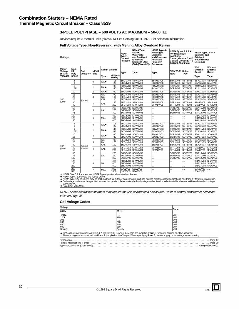
Combination Starters – NEMA RatedThermal Magnetic Circuit Breaker – Class 8539
3-POLE POLYPHASE – 600 VOLTS AC MAXIMUM – 50-60 HZ
Devices require 3 thermal units (sizes 0-6). See Catalog 9065CT9701 for selection information.
Full Voltage Type, Non-Reversing, with Melting Alloy Overload Relays
NOTE: Some control transformers may require the use of oversized enclosures. Refer to control transformer selection table on Page 35.
Coil Voltage Codes
Dimensions . . . . . . . . . . . . . . . . . . . . . . . . . . . . . . . . . . . . . . . . . . . . . . . . . . . . . . . . . . . . . . . . . . . . . . . . . . . . . . . . . . . . . . . . . . . . . . . . . . . . . . . . . . . . . . . . . .Page 17Factory Modifications (Forms). . . . . . . . . . . . . . . . . . . . . . . . . . . . . . . . . . . . . . . . . . . . . . . . . . . . . . . . . . . . . . . . . . . . . . . . . . . . . . . . . . . . . . . . . . . . . . . . . . . .Page 30Type S Accessories (Class 9999) . . . . . . . . . . . . . . . . . . . . . . . . . . . . . . . . . . . . . . . . . . . . . . . . . . . . . . . . . . . . . . . . . . . . . . . . . . . . . . . . . . . . . .Catalog 9999CT9701
Ratings
NEMAType 1GeneralPurpose
NEMA Type4 & 4XWatertightand DusttightEnclosureStainless Steel (304) (Sizes 0-5)u
NEMA Type 4XWatertightDusttightand CorrosionResistantPolyester Enclosure
NEMA Types 7 & 9aFor Hazardous LocationsClass I, Groups C & DClass II, Groups E, F & G (Cast Aluminum)
NEMA Type 12/3RqDusttight and DriptightIndustrial UseEnclosure
MotorVoltage(StarterVoltage)
Max.HPPoly-phase
CoilVoltage t
NEMASize
Circuit BreakerType Type Type SPIN TOP®
TypeBoltedType
WithExternalReset
WithoutExternalReset
Type AmpereRating Type Type
200(208)
23
208-60
0 FALk 1520
SBG1V08SBG3V08
SBW1V08SBW3V08
SBW11V08SBW13V08
SBR1V08SBR3V08
SBT1V08SBT3V08
SBA11V08SBA13V08
SBA1V08SBA3V08
571/2 1 FALk 35
50SCG5V08SCG2V08
SCW5V08SCW2V08
SCW15V08SCW12V08
SCR5V08SCR2V08
SCT5V08SCT2V08
SCA15V08SCA12V08
SCA5V08SCA2V08
10 2 FALk 60 SDG1V08 SDW1V08 SDW11V08 SDR1V08 SDT1V08 SDA11V08 SDA1V08152025
3FALFALKAL
90100110
SEG3V08SEG1V08SEG5V08
SEW3V08SEW1V08SEW5V08
SEW13V08SEW11V08SEW15V08
SER3V08SER1V08SER5V08
SET3V08SET1V08SET5V08
SEA13V08SEA11V08SEA15V08
SEA3V08SEA1V08SEA5V08
3040 4 KAL 125
200SFG3V08SFG4V08
SFW3V08SFW4V08
SFW13V08SFW14V08
SFR3V08SFR4V08
SFT3V08SFT4V08
SFA13V08SFA14V08
SFA3V08SFA4V08
506075
5 LAL200250300
SGG6V08SGG1V08SGG4V08
SGW6V08SGW1V08SGW4V08
....
....
....
SGR6V08SGR1V08SGR4V08
SGT6V08SGT1V08SGT4V08
SGA16V08SGA11V08SGA14V08
SGA6V08SGA1V08SGA4V08
100125150
6 MAL450600600
SHG4V08SHG3V08SHG5V08
SHW4V08SHW3V08SHW5V08
....
....
....
....
....
....
....
....
....
SHA14V08SHA13V08SHA15V08
SHA4V08SHA3V08SHA5V08
230(240)
23
240-60220-50
0 FALk 1520
SBG1V03SBG3V03
SBW1V03SBW3V03
SBW11V03SBW13V03
SBR1V03SBR3V03
SBT1V03SBT3V03
SBA11V03SBA13V03
SBA1V03SBA3V03
571/2 1 FALk 30
45SCG1V03SCG6V03
SCW1V03SCW6V03
SCW11V03SCW16V03
SCR1V03SCR6V03
SCT1V03SCT6V03
SCA11V03SCA16V03
SCA1V03SCA6V03
1015 2 FALk 60
80SDG1V03SDG7V03
SDW1V03SDW7V03
SDW11V03SDW17V03
SDR1V03SDR7V03
SDT1V03SDT7V03
SDA11V03SDA17V03
SDA1V03SDA7V03
202530
3FALFALKAL
90100110
SEG3V03SEG1V03SEG5V03
SEW3V03SEW1V03SEW5V03
SEW13V03SEW11V03SEW15V03
SER3V03SER1V03SER5V03
SET3V03SET1V03SET5V03
SEA13V03SEA11V03SEA15V03
SEA3V03SEA1V03SEA5V03
4050 4 KAL 150
200SFG1V03SFG4V03
SFW1V03SFW4V03
SFW11V03SFW14V03
SFR1V03SFR4V03
SFT1V03SFT4V03
SFA11V03SFA14V03
SFA1V03SFA4V03
6075
1005 LAL
225250350
SGG3V03SGG1V03SGG2V03
SGW3V03SGW1V03SGW2V03
....
....
....
SGR3V03SGR1V03SGR2V03
SGT3V03SGT1V03SGT2V03
SGA13V03SGA11V03SGA12V03
SGA3V03SGA1V03SGA2V03
125150200
6 MAL450600800
SHG4V03SHG3V03SHG7V03
SHW4V03SHW3V03SHW7V03
....
....
....
....
....
....
....
....
....
SHA14V03SHA13V03SHA17V03
SHA4V03SHA3V03SHA7V03
250300 7 MAL 900
1000SJG2V03SJG3V03
SJW2V03SJW3V03
....
............
....
....SJA12V03SJA13V03
....
....u NEMA Size 6 & 7 starters are NEMA Type 4 painted sheet steel enclosures.a NEMA Type 7 & 9 bolted are not UL Listed.q NEMA Type 12 enclosures may be field modified for outdoor non-corrosive and non-service-entrance-rated applications; see Page 17 for more information.t Coil voltage code must be specified to order this product. Refer to standard coil voltage codes listed in selection table above or additional standard voltage
codes below.k Rated 250 Volts Max.
VoltageCode
60 Hz 50 Hz
24jq120j208240480600Specify
. . .110. . .220440550Specify
V01V02V08V03V06V07V99
q 24V coils are not available on Sizes 4-7. On Sizes 00-3, where 24V coils are available, Form S (separate control) must be specified.j These voltage codes must include Form S (supplied at No Charge). When specifying Form S, please supply motor voltage when ordering.
© 1998 Square D All Rights Reserved 1/98

1/98
Combination Starters – NEMA RatedClass 8539 – Thermal Magnetic Circuit Breaker
3-POLE POLYPHASE – 600 VOLTS AC MAXIMUM – 50-60 HZ
Devices require 3 thermal units (sizes 00-6). See Catalog 9065CT9701 for selection information.
Line Voltage Type, Non-Reversing, with Melting Alloy Overload Relays
NOTE: Some control transformers may require the use of oversized enclosures. Refer to control transformer selection table on Page 35.
Thermal Magnetic Circuit Breaker Type, SIngle Phase
Ratings
NEMAType 1GeneralPurposeEnclosure
NEMA Type4 & 4XWatertightand DusttightEnclosureStainless Steel (304) (Sizes 0-5)u
NEMA Type 4XWatertightDusttightand CorrosionResistantPolyester Enclosure
NEMA Types 7 & 9aFor Hazardous LocationsClass I, Groups C & DClass II, Groups E, F & G(Cast Aluminum)
NEMA Type 12/3RqDusttight and DriptightIndustrial UseEnclosure
MotorVoltage(StarterVoltage)
Max.HPPoly-phase
CoilVoltaget
NEMASize
Circuit BreakerType Type Type SPIN TOP®
TypeBoltedType
WithExternalReset
WithoutExternalReset
Type AmpereRating Type Type
460(480)
5
480-60440-50
0 FAL 15 SBG2V06 SBW2V06 SBW12V06 SBR2V06 SBT2V06 SBA12V06 SBA2V0671⁄2
10 1 FAL 2025
SCG3V06SCG7V06
SCW3V06SCW7V06
SCW13V06SCW17V06
SCR3V06SCR7V06
SCT3V06SCT7V06
SCA13V06SCA17V06
SCA3V06SCA7V06
152025
2 FAL406070
SDG3V06SDG4V06SDG5V06
SDW3V06SDW4V06SDW5V06
SDW13V06SDW14V06SDW15V06
SDR3V06SDR4V06SDR5V06
SDT3V06SDT4V06SDT5V06
SDA13V06SDA14V06SDA15V06
SDA3V06SDA4V06SDA5V06
304050
3 FAL8090
100
SEG6V06SEG3V06SEG1V06
SEW6V06SEW3V06SEW1V06
SEW16V06SEW13V06SEW11V06
SER6V06SER3V06SER1V06
SET6V06SET3V06SET1V06
SEA16V06SEA13V06SEA11V06
SEA6V06SEA3V06SEA1V06
6075
1004 KAL
110125200
SFG5V06SFG3V06SFG4V06
SFW5V06SFW3V06SFW4V06
SFW15V06SFW13V06SFW14V06
SFR5V06SFR3V06SFR4V06
SFT5V06SFT3V06SFT4V06
SFA15V06SFA13V06SFA14V06
SFA5V06SFA3V06SFA4V06
125150200
5 LAL225250350
SGG3V06SGG1V06SGG2V06
SGW3V06SGW1V06SGW2V06
....
....
....
SGR3V06SGR1V06SGR2V06
SGT3V06SGT1V06SGT2V06
SGA13V06SGA11V06SGA12V06
SGA3V06SGA1V06SGA2V06
250300350400
6 MAL
450600600800
SHG4V06SHG3V06SHG5V06SHG7V06
SHW4V06SHW3V06SHW5V06SHW7V06
....
....
....
....
....
....
....
....
....
....
....
....
SHA14V06SHA13V06SHA15V06SHA17V06
SHA4V06SHA3V06SHA5V06SHA7V06
500600 7 MAL 900
1000SJG2V06SJG3V06
SJW2V06SJW3V06
....
............
....
....SJA12V06SJA13V06
....
....
575(600)
5
600-60550-50
0 FAL 15 SBG2V07 SBW2V07 SBW12V07 SBR2V07 SBT2V07 SBA12V07 SBA2V0771⁄2
10 1 FAL 1520
SCG8V07SCG3V07
SCW8V07SCW3V07
SCW18V07SCW13V07
SCR8V07SCR3V07
SCT8V07SCT3V07
SCA18V07SCA13V07
SCA8V07SCA3V07
152025
2 FAL354560
SDG8V07SDG9V07SDG4V07
SDW8V07SDW9V07SDW4V07
SDW18V07SDW19V07SDW14V07
SDR8V07SDR9V07SDR4V07
SDT8V07SDT9V07SDT4V07
SDA18V07SDA19V07SDA14V07
SDA8V07SDA9V07SDA4V07
304050
3 FAL608090
SEG4V07SEG6V07SEG3V07
SEW4V07SEW6V07SEW3V07
SEW14V07SEW16V07SEW13V07
SER4V07SER6V07SER3V07
SET4V07SET6V07SET3V07
SEA14V07SEA16V07SEA13V07
SEA4V07SEA6V07SEA3V07
6075
1004
FALKALKAL
100110150
SFG6V07SFG5V07SFG1V07
SFW6V07SFW5V07SFW1V07
SFW16V07SFW15V07SFW11V07
SFR6V07SFR5V07SFR1V07
SFT6V07SFT5V07SFT1V07
SFA16V07SFA15V07SFA11V07
SFA6V07SFA5V07SFA1V07
125150200
5KALLALLAL
200200250
SGG7V07SGG6V07SGG1V07
SGW7V07SGW6V07SGW1V07
....
....
....
SGR7V07SGR6V07SGR1V07
SGT7V07SGT6V07SGT1V07
SGA17V07SGA16V07SGA11V07
SGA7V07SGA6V07SGA1V07
250300350400
6 MAL
350450500600
SHG6V07SHG4V07SHG2V07SHG3V07
SHW6V07SHW4V07SHW2V07SHW3V07
....
....
....
....
....
....
....
....
....
....
....
....
SHA16V07SHA14V07SHA12V07SHA13V07
SHA6V07SHA4V07SHA2V07SHA3V07
500600 7 MAL 800
900SJG1V07SJG2V07
SJW1V07SJW2V07
....
............
....
....SJA11V07SJA12V07
....
....u NEMA Size 6 & 7 starters are NEMA Type 4 painted sheet steel enclosures. a NEMA Type 7 & 9 bolted are not UL Listed.q NEMA Type 12 enclosures may be field modified for outdoor non-corrosive and non-service-entrance-rated applications; see Page 17 for more information.t Coil voltage code must be specified to order this product. Refer to standard coil voltage codes listed in selection table above or additional standard voltage
codes below.
MotorVoltage
Max.HP
CoilVoltage
NEMASize
Circuit Breaker(Type)
Ampere Rating
NEMA Type 1General Purpose Enclosure
NEMA Type 4 & 4XWatertight and Dusttight EnclosureStainless Steel (304) (Sizes 0-5)u
NEMA Type 4XWatertight, Dusttight and Corrosion Resistant Polyester Enclosure
NEMA Type 12/3RqDusttight and Driptight Industrial Use Enclosure
WithExternal Reset
WithoutExternal Reset
Type Type Type Type Type
120123
120012
FAL12030FAL12050FAL12070
305070
SBG1S2V02SCG1S2V02SDG1S2V02
SBW1S2V02SCW1S2V02SDW1S2V02
SBW31S2V02SCW31S2V02SDW31S2V02
SBA21S2V02SCA21S2V02SDA21S2V02
SBA1S2V02SCA1S2V02SDA1S2V02
2302371⁄2
230012
FAL22025FAL22035FAL22080
253580
SBG1S2V03SCG1S2V03SDG1S2V03
SBW1S2V03SCW1S2V03SDW1S2V03
SBW31S2V03SCW31S2V03SDW31S2V03
SBA21S2V03SCA21S2V03SDA21S2V03
SBA1S2V03SCA1S2V03SDA1S2V03
11© 1998 Square D All Rights Reserved

12
Full Voltage Contactors and Starters – NEMA RatedApplication Data for Selection
NEMASize
LoadVolts
MaximumHPRating–NonpluggingandNonjoggingDuty
MaximumHPRating–PluggingandJoggingDutyj
Contin-uousCurrentRating,Amperes–600 VoltMax.
Service—LimitCurrentRating,Amperest
TungstenandInfraredLamp Load,Amperes–250 VoltsMax.a
ResistanceHeatingLoads, KW –other thanInfraredLamp Loadsu
KVA Rating for SwitchingTransformer Primaries At50 or 60 Cycles
3 PHRating forSwitchingCapacitorsk
TransformersHaving InrushCurrents (WorstCase Peak) ofNot More Than20 Times Peakof ContinuousCurrent Rating
TransformersHaving InrushCurrents (WorstCase Peak) ofOver 20 Through40 Times Peakof ContinuousCurrent Rating
SinglePhase
Poly-Phase
SinglePhase
Poly-Phase
SinglePhase
Poly-Phase
SinglePhase
Poly-Phase
SinglePhase
Poly-Phase KVAR
00
115200230380460575
1/2. . .1
. . .
. . .
. . .
. . . 11/2
11/2 11/222
. . .
. . .
. . .
. . .
. . .
. . .
. . .
. . .
. . .
. . .
. . .
. . .
999999
111111111111
555
. . .
. . .
. . .
. . .
. . .
. . .
. . .
. . .
. . .
. . .
. . .
. . .
. . .
. . .
. . .
. . .
. . .
. . .
. . .
. . .
. . .
. . .
. . .
. . .
. . .
. . .
. . .
. . .
. . .
. . .
. . .
. . .
. . .
. . .
. . .
. . .
. . .
. . .
. . .
. . .
. . .
. . .
. . .
. . .
. . .
0
115200230380460575
1. . .2
. . .
. . .
. . .
. . .33555
1/2. . .1
. . .
. . .
. . .
. . . 11/2
11/2 11/222
181818181818
212121212121
101010
. . .
. . .
. . .
. . .
. . .
. . .
. . .
. . .
. . .
. . .
. . .
. . .
. . .
. . .
. . .
0.6. . .
1.2. . .
2.43.0
. . .1.82.1
. . .4.25.2
0.3. . .0.6
. . .1.21.5
. . .0.91.0
. . .2.12.6
. . .
. . .
. . .
. . .
. . .
. . .
1
115200230380460575
2. . .3
. . .
. . .
. . .
. . . 71/2 71/2101010
1. . .2
. . .
. . .
. . .
. . .33555
272727272727
323232323232
151515
. . .
. . .
. . .
3. . .
6. . .1215
59.1
1016.52025
1.2. . .
2.4. . .
4.96.2
. . .3.64.3
. . .8.5
11.0
0.6. . .1.2
. . .2.53.1
. . .1.82.1
. . .4.35.3
. . .
. . .
. . .
. . .
. . .
. . .
1P 115230
35
. . .
. . . 11/23
. . .
. . .3636
4242
2424
. . .
. . .. . .. . .
. . .
. . .. . .. . .
. . .
. . .. . .. . .
. . .
. . .
2
115200230380460575
3. . . 71/2. . .. . .. . .
. . .1015252525
2. . .5
. . .
. . .
. . .
. . . 71/2
10151515
454545454545
525252525252
303030
. . .
. . .
. . .
5. . .10
. . .2025
8.515.417283443
2.1. . .
4.1. . .
8.310.0
. . .6.37.2
. . .1418
1.0. . .2.1
. . .4.25.2
. . .3.13.6
. . .7.28.9
. . .
. . .8
. . .1620
3
115200230380460575
. . .
. . .
. . .
. . .
. . .
. . .
. . .2530505050
. . .
. . .
. . .
. . .
. . .
. . .
. . .1520303030
909090909090
104104104104104104
606060
. . .
. . .
. . .
10. . .20
. . .4050
173134566886
4.1. . .
8.1. . .1620
. . .1214
. . .2835
2.0. . .4.1
. . .8.1
10
. . .6.17.0
. . .1418
. . .
. . .27
. . .5367
4
200230380460575
. . .
. . .
. . .
. . .
. . .
405075
100100
. . .
. . .
. . .
. . .
. . .
2530506060
135135135135135
156156156156156
120120. . .. . .. . .
. . .30
. . .6075
455286.7
105130
. . .14
. . .2734
2023
. . .4759
. . .6.8
. . .1417
1012
. . .2329
. . .40
. . .80
100
5
200230380460575
. . .
. . .
. . .
. . .
. . .
75100150200200
. . .
. . .
. . .
. . .
. . .
6075
125150150
270270270270270
311311311311311
240240. . .. . .. . .
. . .60
. . .120150
91105173210260
. . .27
. . .5468
4147
. . .94
117
. . .14. . .2734
2024
. . .4759
. . .80
. . .160200
6q
200230380460575
. . .
. . .
. . .
. . .
. . .
150200300400400
. . .
. . .
. . .
. . .
. . .
125150250300300
540540540540540
621621621621621
480480. . .. . .. . .
. . .120. . .240300
182210342415515
. . .54
. . .108135
8194
. . .188234
. . .27. . .5468
4147
. . .94
117
. . .160. . .320400
7q230460575
. . .
. . .
. . .
300600600
. . .
. . .
. . .
. . .
. . .
. . .
810810810
932932932
. . .
. . .
. . .
180360450
315625775
. . .
. . .
. . .
. . .
. . .
. . .
. . .
. . .
. . .
. . .
. . .
. . .
240480600
Tables and footnotes are taken from NEMA Standards.
j Ratings shown are for applications requiring repeated interruptions of stalled motor current or repeated closing of high transient currents encountered in rapid motor reversal, involving more than five openings or closings per minute and more than ten in a ten-minute period, such as plug-stop, plug-reverse or jogging duty. Ratings apply to single speed and multi-speed controllers.
t Per NEMA Standards ICS 2-1993 clause 4, the service-limit current represents the maximum rms current, in Amperes, which the controller may be expected to carry for protracted periods in normal service. At service-limit current ratings, temperature rises may exceed those obtained by testing the controller at its continuous current rating. The ultimate trip current of over-current (overload) relays or other motor protective devices shall not exceed the service-limit current ratings of the controller.
a FLUORESCENT LAMP LOADS – 300 VOLTS AND LESS – The characteristics of fluorescent lamps are such that it is not necessary to derate Class 8502 contactors below their normal continuous current rating. Class 8903 contactors may also be used with fluorescent lamp loads. For controlling tungsten and infrared lamp loads, and resistance heating loads, Class 8903 ac lighting contac-tors are recommended. These contactors are specifically designed for such loads and are applied at their full rating as listed in the Class 8903 Section.
u Ratings apply to contactors which are employed to switch the load at the utiliza-tion voltage of the heat producing element with a duty which requires continuous operation of not more than five openings per minute. Class 8903 Types L and S lighting contactors are rated for resistance heating loads.
k When discharged, a capacitor has essentially zero impedance. For repeti-tive switching by a contactor, sufficient impedance should be connected in series to limit inrush current to not more than 6 times the contactor rated continuous current. In many installations, the impedance of connecting conductors may be sufficient for this purpose. When switching to connect additional banks, the banks already on the line may be charged and can supply additional available short-circuit current which should be considered when selecting the impedance to limit the current.The ratings for capacitor switching above assume the following maximum available fault currents:NEMA Size 2-3: 5,000 A RMS Sym.NEMA Size 4-5: 10,000 A RMS Sym.NEMA Size 6: 18,000 A RMS Sym.NEMA Size 7: 30,000 A RMS Sym.If available fault current is greater than these values, connect sufficient impedance in series as noted in the previous paragraph.
q For NEMA Size 6 and 7, the operation rate is as follows: Continuous operation rate is 3 operations per minute maximum; Jogging or Plugging Duty operation rate is 15 operations per minute for a maximum of three minutes.
The motor ratings in the above table are NEMA standard ratings and apply only when the code letter of the motor is the same as or occurs earlier in the alphabet than is shown in the table below.Motors having code letters occurring later in the alphabet may require a larger controller. Consult local Square D field office.
Motor HP Rating Maximum Allowable Motor Code Letter
11/2-23-571/2 and above
LKH
© 1998 Square D All Rights Reserved 1/98

1/98
Full Votage Contactors and Starters – NEMA RatedApplication Data
Power Contact Ratings: All contactors and starters are rated in accordance with NEMA standards. The ratings shown in the selection tables are for normal service. For complete data on power contact ratings, refer to Page 12.
Short Circuit Protection: According to the National Electrical Code branch circuit overcurrent protection must be provided for each contactor or starter. For starters refer to instructions furnished with the thermal unit selection table. For contactors (Class 8502 or 8702) provide branch circuit overcurrent protection in accordance with the National Electrical Code, except do not exceed the maximum protective device ratings in table below.
Capacitor Switching: The kilovar ratings of enclosed, three phase contactors used as switches for capacitor loads, when only one load appears on the secondary of a distribution system are shown in the table on Page 12.
Maintenance of Equipment: Class 9998 Repair Parts Kits are available for all Class 8502 contactors and Class 8536 starters. Service bulletins with a complete list of replaceable parts are supplied with all enclosed devices. Separate bulletins can be ordered and are listed along with the appropriate contact parts kit.
NEMASize
MaximumVoltage
ClassK5, RK5 or RK1Fuse(Ampere)
ClassJ or TFuse(Ampere)
Inverse-TimeCircuitBreaker(Ampere)
00600 10 15 15
250 12 15 15
0600 20 30 20
250 25 30 35
1600 30 60 40
250 40 60 60
2600 60 100 80
250 60 100 90
3600 100 200 125
250 125 200 150
4 600 200 400 225
5 600 400 600 400
6 600 600 1200t 800
7 600 600 1600t 1200
t Class L Fuse only
Coil Burdenq
NEMASize
No.ofPoles
Inrush VA Sealed VA Sealed Watts
50 Hz 60 Hz 50 Hz 60 Hz 50 Hz 60 Hz
00 2-3 . . . . 165 . . . . 33 . . . . 6
0 & 1 1-5 232 245 26 27 7.7 7.8
22 & 3 296 311 36 37 12 14
4 & 5 429 438 37 38 12 14
32-3 676 700 47 46 15 14
4-51260 1185 89 85 23.4 22
4 2-5
5 2-3 2970 2970 250 212 42 39
6u 2-3 1495 1780 56 48 27 32
7u 2-3 . . . . 1960 . . . . 59 . . . . 36
q Mean values.u Size 6 and 7 have a DC coil. The values shown are for the AC input to the
DC power supply that provides power to the coil.Ambient temperature (operating temperature): 0˚C - 40˚C (32˚F - 104˚F)
DeviceInstructionBulletin
ServiceBulletin
ReplacementContactsClass 9998TypeN
EM
ATy
peTy
pe
Ser
ies
No. ofPoles
00 SAA 2-3 362AS SL2
B 2-3 30072-013-08 556AS SJ1
0 SB A&B1-345
30072-013-09277AS277AS & 250AS277AS & 250AS
SL2 SL12
(1)SL12 & (1)SL22or(1)SL2 & (2)SL22
1 SC A&B1-345
30072-013-10278AS278AS & 250AS278AS & 250AS
SL3 SL13
(1)SL13 & (1)SL22or(1)SL3 & (2)SL22
1P SC A 2 30072-013-10 278AS SL3
2 SD A2-345
30072-013-11279AS279AS & 293AS279AS & 293AS
SL4 SL14
(1)SL14 & (1)SL24or(1)SL4 & (2)SL24
3 SE A
2345
30072-013-0130072-013-0130072-013-0330072-013-03
305AS305AS326AS326AS
SL6 SL7
(2)SL6(1)SL6 & (1)SL7
4 SF A
2345
30072-013-0230072-013-0230072-013-0330072-013-03
306AS306AS326AS326AS
SL8 SL9
(2)SL8(1)SL8 & (1)SL9
5 SG A 23
30072-013-1830072-013-18
328AS328AS
SL10 SL11
6 SHA 2
3342AS342AS
SL25 SL26
B 23
30072-013-1230072-013-12
370AS370AS
SL25 SL26
7 SJ A 23
30072-013-1330072-013-13
397AS397AS
SL30 SL31
Terminals
NEMASize Type
Power Terminals Control Terminals
Typeof Lug
WireSizestMin.-Max.
Typeof Lug
WireSizestMin.-Max.
00,0 & 1
SA, SB& SC
PressureWire #14-#8 Pressure
Wire #16-#12
2 SD BoxLug #14-#4 Pressure
Wire #16-#12
3 SE BoxLug #14-1/0 Pressure
Wire #16-#12
4 SF BoxLug #8-250 kcmil Pressure
Wire #16-#12
5 SG BoxLug #4-500 kcmil Pressure
Wire #16-#12
6 SH ParallelGroove
One or two250-500 kcmilper phase
PressureWire #16-#12
7 SJ ParallelGroove
One to four250-500 kcmilper phase
PressureWire #16-#12
t Solid or stranded copper wire. One wire per connector.Coil temperature: Not more than 85˚C rise in 40˚C ambient (125˚C max.).
13© 1998 Square D All Rights Reserved

14
Full Voltage Contactors & Starters – NEMA RatedApplication Data
Auxiliary Units
Auxiliary contacts, power poles, and timer attachments can be added by the factory or in the field on all Type S starters and contactors. The table below shows the maximum number of auxiliary units (in addition to the holding circuit contact) that can be added to a given size starter or contactor. In addition, it is possible to add a second internal contact on NEMA Size 0, 1, and 2 contactors and starters.
Factory Installed Auxiliary Contacts
The table below lists the Form designations for factory installed electrical contacts. See Factory Modifications (Forms) section for pricing.
See Class 9999 for field modification kits.
Form NumberOf Additional Auxiliary Contacts
When ordering factory installed auxiliary contacts, the Form designations listed should be used.
Control Circuit Transformers
Class 9070 Type T control transformers are normally used when it is necessary to provide a lower voltage to the control circuit. This transformer with fused protection may be ordered from the factory by specifying Form F4T. The addition of a transformer often requires the use of a larger enclosure (refer to dimensions on Page 17–19). The table below shows the transformer selection for given sized starters and contactors with or without auxiliary units.
Power Poles
Single or double circuit power pole adders may be factory or field installed on 2 and 3 pole Type S contactors and starters. The table below lists the Form designation for factory installed power pole adders. Only one power pole adder may be installed per contactor. See Factory Modifications (Forms) section for pricing.
See Class 9999 for field modification kits.
NEMASize Type
No. ofPoles ofBasicCon-tactor
Maximum Number of External Auxiliary Units(In addition to holding circuit contact)
00 SA 2-3 4 single circuit auxiliary contacts (N.O. or N.C.) if second internal auxiliary contact is not used.
0, 1and 2
SBSCSD
1, 2 or 3
4 single circuit auxiliary contacts (N.O. or N.C.)
3 single circuit auxiliary contacts (N.O. or N.C.) plus 1 attached timer (ON or OFF delay).
2 single circuit auxiliary contacts (N.O. or N.C.) plus 1 power pole adder (1 or 2 poles, N.O. or N.C.).
1 attached timer (ON or OFF delay) plus 1 power pole adder (1 or 2 poles, N.O. or N.C.) plus 1 auxiliary contact.
4 or 5 2 single circuit auxiliary contacts (N.O. or N.C.)1 timer attachment plus 1 auxiliary contact.
3, 4 & 5
SESFSG
2–5(Size3 & 4)
4 single circuit auxiliary contacts (N.O. or N.C.)
2 single circuit (Sizes 3 & 4) or 3 single circuit (Size 5) auxiliary contacts plus 1 attached timer (ON or OFF delay).
2-3(Size 5)
2 single circuit auxiliary contacts (N.O. or N.C.) plus 1 NEMA Size 0-1 or Size 2 power pole adder (1 or 2 poles, N.O. or N.C.)
6and7
SHSJ 2-3
4 single circuit auxiliary contacts (N.O. or N.C.)
3 single circuit auxiliary contacts (N.O. or N.C.) plus 1 attached timer (ON or OFF delay).
2 single circuit auxiliary contacts (N.O. or N.C.) plus 1 NEMA Size 0-1 or Size 2 power pole adder (1 or 2 poles, N.O. or N.C.)
Number ofN.O. Contacts
Number ofN.C. Contacts
FormNumber
0000
1234
X01X02X03X04
1111
0123
X10X11X12X13
222
012
X20X21X22
334
010
X30X31X40
NEMASize Type No. of
Poles Auxiliary Units
Trans-formerClass 9070Type
0 & 1 SBSC 1-3
With max. of 2 auxiliary contacts
T50With timer and maximum of 1 auxiliary contact
With 3 or 4 auxiliary contactsWith timer and 2 or 3 auxiliary contacts
T100
0 & 1 SBSC 4 & 5 With or without auxiliary
contacts or timer T100
0 & 1MechanicallyInterlockedDevices
SBSC 1-5 With or without attachments T100
2 SD 2-5 With or without attachments T100
3 SE 2-3 With or without attachments T150
3 SE 4 & 5 With or without attachments T300
4 SF 2-5 With or without attachments T300
5 SG 2-3 Any T500
6, 7 SH, SJ 2-3 Any u
u A Class 9070 transformer is an integral part of the Size 6 and Size 7 control circuit providing 120 volt control circuit voltage as standard.
Type NEMASize
Class 9999Type
FormDesignation
1 N.O. 0, 12
SB6SB11
Y428Y436
1 N.C. 0, 12
SB7SB12
Y429Y437
1 N.O., 1 N.C. 0, 12
SB8SB13
Y435Y440
2 N.O. 0, 12
SB9SB14
Y430Y438
2 N.C. 0, 12
SB10SB15
Y434Y439
File E61239CCN XPTQ
File LR37055Class 5411 06
File E78360CCN NITW2
Transformers
© 1998 Square D All Rights Reserved 1/98

1/98
Full Voltage Contactors and Starters – NEMA RatedApplication Data
NEMA Size 6 Type SH and NEMA Size 7 Type SJ contactors and starters have a DC coil operated by a solid state rectifier circuit mounted on the device and powered from an ac source. The NEMA Sizes 6 and 7 are equipped as standard with a fused control circuit transformer (Form F4T) rated 240/480-120 volts 60 Hz, 220/440-110 volts 50 Hz. The purpose of this transformer is to provide an isolated 120 volts 60 Hz, 110 volts 50 Hz, supply for the control circuit. NEMA Sizes 6 and 7 may be ordered for other system voltages by specifying the voltage and frequency desired.
Operation Rates – Continuous operation rate: 3 operations/minute maximum. Jogging or Plugging Duty: 15 operations/minute - 3 minutes maximum.
Field conversion for other system voltages is accomplished by one of the following methods, NOT BY THE USUAL PRACTICE OF CHANGING THE COIL:
1. If the factory wiring is indicated as being for 480 volts 60 Hertz, 440 volts 50 Hertz, conversion to 240 volts 60 Hertz, 220 volts 50 Hertz, can be accomplished by reconnecting the control transformer as illustrated on instruction sheet supplied with the controller. This is the same method that would be used on Class 9070 control circuit transformers.
Conversion to any other voltage requires replacement of the control transformer. For other system voltages: i.e. 208, 277, 380, 600 volts, a new transformer with single voltage primary must be selected from table at right. Control transformer connections are illustrated on the instruction sheet supplied with the controller.
2. If the factory wiring is indicated as being for any voltage other than 480 volts 60 Hertz, 440 volts 50 Hertz, conversion to any other voltage requires replacement of the control transformer. Refer to table at right.
3. In Square D combination starters, the standard transformer supplied may be used to power a maximum of five Class 9001 Type K illuminated operators powered with transformer type light modules. When extra capacity to power control relays or other inductive loads is required, a second transformer must be added. Extra capacity can be purchased as Form F4T with additions in 100 VA increments.
4. Standard controllers are wired for common control and are not convertible for operation of the control circuit from a separate source of supply voltage. Controllers designated Form S have special wiring designed for separate control. They are furnished with an isolating transformer, usually having a 120 volt primary and 120 volt secondary, that must not be bypassed. Form S controllers are not convertible for operation on common control.
The tables below give the replacement transformers for Type S NEMA Sizes 6 and 7 contactors and starters. To change voltages on these devices, coils are not changed, instead transformers with the desired voltage are changed.
Auxiliary Contacts: A N.O. holding circuit contact and a N.C. auxiliary contact are provided as standard. The holding circuit contact may or may not be required for either 3-wire or 2-wire control. NEMA Sizes 6 and 7 have an additional N.C. auxiliary contact which is wired in the coil control circuit. DO NOT USE THIS N.C. CONTACT FOR ANY OTHER PURPOSE.
Replacement Control Transformers (150VA) For Type S Size 6Voltage Class
9070Type60 Hertz 50 Hertz
240/480-120208-120277-120. . . . . . . .600-120120-120240-120
220/440-110. . . . . . . .. . . . . . . .380-110550-110110-110220-110
31104-512-5031104-512-5231104-512-5331104-512-5431104-512-5131104-512-5531104-512-56
Replacement Control Transformers (200VA) For Type S Size 7Voltage Class
9070Type60 Hertz 50 Hertz
240/480-120208-120277-120. . . . . . . .600-120120-120240-120
220/440-110. . . . . . . .. . . . . . . .380-110550-110110-110220-110
31123-501-5031123-501-5231123-501-5331123-501-5431123-501-5131123-501-5531123-501-56
NEMA Size 6 Starter8536 SH
NEMA Size 7 Starter8536 SJ
15© 1998 Square D All Rights Reserved

16
Combination Starters – NEMA RatedApplication Data – Class 8538, 8539
Class 8539 – UL Listed Short Circuit Ratings
Table 1: MAG-GARD Trip Range
Class 8539 – UL Listed Short Circuit Ratings
Class 8538 – UL Listed Short Circuit Ratings
Table 2: Motor Code Letter Table
Terminals
MAG-GARD® Motor Circuit Protector Type
NEMA Size Voltage Enclosure Available AmperesRMS Symmetrical
0 & 1, 2Size 3 Type SEt41 & SEt51 Only (GJL)
0-480 Standardj andOversize 100,000
0 & 1 (FAL) 0-480 Standardj andOversize 22,000
0 & 1 (FAL) 481-600 Standardj andOversize 10,000
0 & 1, 2Size 3 Type SEt41 & SEt51 Only (GJL)
481-600 Standardj andOversize 10,000
0-2 with Current Limiting Module 600 Oversize 100,000
0-3 with Current Limiting Module 600 Standardj 100,000
0-3 600 NEMA 7 & 9 5,000•2 600 Oversize 22,0002-6 600 Standardj 22,0004 & 5 600 NEMA 7 & 9 10,0007 0-480 Standardj 30,0007 481-600 Standardj 22,000j Standard enclosure includes non-oversize NEMA Types 1, 4 & 4X
Stainless, and 12.k Consult factory for higher withstand ratings.
SuffixNo.
SuffixNo.
RangeAmps
SuffixNo.
RangeAmps
SuffixNo.
RangeAmps
M01 9-33 11M 8-28 25M 625-1250 33M 1500-3000M02 21-77 12M 18-70 26M 750-1500 35M 1750-3500M03 45-165 13M 50-180 29M 875-1750 36M 2000-4000M04 90-330 15M 100-350 30M 1000-2000 40M 2500-5000M05 150-550 16M 150-580 31M 1125-2250 42M 3000-6000M06 225-825 18M 300-1100 32M 1250-2500 44M 3500-7000The MAG-GARD adjustable trip range is determined by the suffix of the circuit breaker catalog number. Table 1 indicates the trip range which corresponds to a given suffix number. The MAG-GARD Motor Circuit Protector should be adjusted to a level just above Locked-Rotor Current of the motor. This setting will provide optimum overcurrent protection for the motor. For more information on MAG-GARD instantaneous trip circuit breakers, refer to the MAG-GARD circuit breaker section of this Catalog.
Thermal Magnetic Circuit Breaker TypeNEMASize Voltage Enclosure Available Amperes
RMS Symmetrical0-3 600 Standardj 5,0004 & 5 600 Standardj 10,0006 600 Standardj 18,0007 0-480 Standardj 30,0007 481-600 Standardj 22,000j Standard enclosure includes non-oversize NEMA Types 1, 4 & 4X Stain-
less, and 12.
NEMA Size NEMA FuseClass Enclosure
AvailableAmperes RMSSymmetrical
0-3 Class H or K Standardj 5,0000-3 Class R Standardj 100,0000-2 Class H or K Oversize 5,0000-2 Class R Standard 100,0004-5 Class H or K Standardj 10,0004-5 Class R Standardj 100,0006 Class H or K Standardj 18,0006 Class R Standardj 100,000j Standard enclosure includes non-oversize NEMA Types 1, 4 & 4X Stain-
less, and 12.
Horsepower Motor Code Letters1⁄2 or less A-L3⁄4 — 11⁄2 A-K2 — 3 A-J5 — 25 A-H30 — 125 A-G150 or more A-FThe combination starter selection tables on Pages 7 —9 are suitable for motors with Locked-Rotor Current letters per NEC Table 430-7(b) as listed in Table 2. For other motors a special thermal magnetic circuit breaker with adjustable magnetic trip settings for the specific motor is required. When ordering for these special applications, specify the motor horsepower, voltage, frequency, full load current and code letter (or locked rotor current) to assure proper protection.
NEMASize Type
Line Terminals on Disconnect Power Terminals On Magnetic Starter Control Terminals On Magnetic Starter
Typeof Lug
Wire Size Min.-Max. Type ofLug
Wire SizeMin.-Max.
Wires PerTerminal
Type ofLug
Wire SizeMin.-Max.
Wires PerTerminalSwitch Circuit Breaker
0 & 1 SB & SC
Box Lug #14-1/0 Cu/Al
#14-#4 Cup#12-#4 Al or #14-#1/0 Cu#12-#1/0 Al#14-#1 Cu/#8-#1/0 Al (GJL Breaker)
PressureWire #14-#8 Cu 1 or 2 Pressure
Wire #16-#12 Cu 2
2 SD Box Lug #14-1/0 Cu/Al #14-#1/0 Cu or #12-#1/0 Al
#14-#1 Cu/#8-#1/0 Al (GJL Breaker) Box Lug #14-#4 Cu 1 Pressure Wire #16-#12 Cu 2
3 SE Box Lug #14-1/0 Cu/Al
#14-#2 Cu#10-#2 Al (FA Breaker)#4-300 MCM Cu/Al (KA Brkr)#14-#1 Cu/#8-#1/0 Al (GJL Breaker)
Box Lug #14-#0 Cu 1 Pressure Wire #16-#12 Cu 2
4 SF BoxLug #6-300 MCM Cu/Al
#14-#1/0 Cu#12-#1/0 Al (FA Breaker)#4-300 MCM Cu/Al (KA Brkr)
Box Lug #8-250 MCM Cu 1 Pressure Wire #16-#12 Cu 2
5 SG BoxLug One #4-500 MCM Cu
#4-300 MCM Cu/AL (KA Breaker)(1)#1-600 MCM or(2)#1-250 MCM Cu/Al (LA Brkr)
Box Lug #4-500 MCM Cu 1 Pressure Wire #16-#12 Cu 2
6 SH Box Lug . . . .
(1)#1-600 MCM or(2)#1-250 MCM Cu/Al (LA Breaker)(3)#3/0-500 MCM Cu/Al (MA Brkr)
Parallel Groove 250-500 MCM Cuk 1 or 2 Pressure
Wire #16-#12 Cuq 2
7 SJ Box Lug . . . . (3)#3/0-500 MCM Cu/Al Parallel
Groove 250-500 MCM Cu 1-4 Pressure Wire #16-#12 Cu 2
k Order Class 9999 Type SAL-16 parts kit to convert power terminals to accept sizes 1/0-300 MCM wire.q Terminal block range limited to #16-#14.p Use on FAL circuit breakers rated 25 Amps or less.
© 1998 Square D All Rights Reserved 1/98

1/98
Combination Starters — NEMA RatedApproximate Dimensions, Shipping Weights – Class 8538, 8539
NEMA
E
KMD
A
F
W X W
G
JH
I
Cover Open 90°
NEMA Type 1 Enclosure – Figure 1
NEMA Type 1 Enclosure – Figure 2
NEMA Type 12 Enclosure – Figure 3
NOTE: Illustrations may not represent the actual enclosure, they are intended for dimensional information only.
NEMA Type 12 Enclosures Modified for Outdoor Applications (not to be used in salt air or corrosive environments)
Field Modifications for NEMA Type 3 dusttight, raintight and sleet resistant outdoor applications are as follows: Watertight conduit hubs or equivalent provision for watertight connection at the conduit entrance shall be used.
Field Modifications for NEMA Type 3R rainproof and sleet resistant outdoor applications are as follows:
1. Watertight conduit hubs or equivalent provision for watertight connection at the conduit entrance, when the conduit enters at a level higher than the lowest live part, shall be used.
2. Drain holes of 1/8 inch diameter shall be added to the bottom of the enclosure.
NEMASize Class Type
Dimensions in Inchest Top & Bottom Sides Wt.(Lbs.)A B C D E F G H I J K L M N O P W X Y
0-1 8538 & 8539
SBGSCG 91⁄2 221⁄2 811⁄32 63⁄8 201⁄2 1421⁄32 113⁄16 111⁄16 3 25⁄16 11⁄16 31⁄4 23⁄16 11⁄4 7⁄8 . . . 1⁄2-3⁄4 1⁄2-3⁄4 1⁄2 38
2 8538 & 8539 SDG 101⁄2 26 919⁄32 73⁄8 24 1629⁄32 21⁄8 2 4 25⁄16 11⁄16 31⁄4 23⁄16 11⁄4 7⁄8 . . . 1-11⁄4 1⁄2-3⁄4 1⁄2 54
t Above dimensions include space for control circuit transformers.
NEMASize Class Type
Dimensions in Inchest Top & Bottom Sides Wt.(Lbs.)A B C D E F G H I J K L M N O P W X Y
3c 8538 & 8539 SEG 151⁄4 42 1019⁄32 91⁄4 3 2223⁄32 41 1⁄2 . . . 253⁄64 317⁄32 5 211⁄16 53⁄8 19⁄32 29⁄32
1-11⁄42-21⁄2
1⁄2-3⁄4 1⁄2 102
48538 SFG 16 521⁄2 1017⁄32 10 3 2321⁄32 511⁄2 1⁄2 . . . 253⁄64 317⁄32 5 211⁄16 53⁄8 19⁄32 29⁄32 21⁄2 1⁄2-3⁄4 1⁄2 1638539 SFG 16 521⁄2 1017⁄32 10 3 2321⁄32 511⁄2 1⁄2 . . . 253⁄64 317⁄32 5 211⁄16 53⁄8 19⁄32 29⁄32 21⁄2 1⁄2-3⁄4 1⁄2 163
58538 SGG 20 78 151⁄2 12 4 2913⁄32 77 1⁄2 . . . 333⁄64 439⁄64 91⁄4 33⁄16 . . . . . . . . . 1⁄2-3⁄4j 3 . . . 4508539 SGG 20 66 1323⁄32 12 4 2913⁄32 65 1⁄2 . . . 333⁄64 439⁄64 5 33⁄16 . . . . . . . . . 1⁄2-3⁄4j 3 . . . 420
6q 8538 & 8539 SHG 36 90 211⁄32 . . . . . . 413⁄8 . . . . . . . . . . . . . . . 5 . . . . . . . . . . . . . . . . . . . . . . . .
j Left side only q Size 6 enclosures are floor mounting.t Above dimensions include space for control circuit transformers.c Class 8538 Size 3 devices with 200 Amp fuse clips use dimensions for Class 8538 Size 4.
NEMASize Class Type
Dimensions in Inchest Wt.(Lbs.)A B C D E F G H I J
0-1 8538 & 8539 SBASCA 91⁄2 811⁄32 24 31⁄4 21⁄2 41⁄2 231⁄2 19⁄32 47⁄16 145⁄16 40
2 8538 & 8539 SDA 101⁄2 919⁄32 273⁄4 31⁄4 21⁄2 51⁄2 27 3⁄8 41⁄8 169⁄16 553c 8538 & 8539 SEA 151⁄4 1019⁄32 42 5 3 91⁄4 41 1⁄2 51⁄16 225⁄16 111
48538 SFA 16 1017⁄32 521⁄2 5 3 10 511⁄2 1⁄2 43⁄16 2231⁄32 1708539 SFA 16 1017⁄32 521⁄2 5 3 10 511⁄2 1⁄2 53⁄16 2231⁄32 170
58538 SGA 20 1323⁄32 78 91⁄4 4 12 77 1⁄2 725⁄32 2913⁄32 . . .8539 SGA 20 1323⁄32 66 5 4 12 65 1⁄2 725⁄32 2713⁄32 440
6q 8538 & 8539 SHA 36 17 90 5 . . . . . . . . . . . . . . . 473⁄8 . . .q Size 6 enclosures are floor mounting.t Above dimensions include space for control circuit transformers.c Class 8538 Size 3 devices with 200 Amp fuse clips use dimensions for Class 8538 Size 4.
Figure 1 Type 1 Enclosure
Figure 2NEMA Type 1 Enclosure
Figure 3NEMA Type 12 Enclosure
YO
N
C
HandleSwitch
B
Y
(4) .31 DIA. MTG.HOLES (FOR SIZE 0, 1, & 2)8
(4) .44 DIA. MTG. HOLES (FOR SIZE 3 & 4)11
(4) .56 DIA. MTG. HOLES LOCATED ON
14 EXTERNAL FLANGES (FOR SIZE 5)
C30053-173G
LDA
E H
LHandleSwing
C
P
O
Y
BG
Y
J
NM
K
W X W
F
DIA.MTAG. HOLES (FOR SIZE 0, 1, & 2)
DIA.MTAG. HOLES (FOR SIZE 3 & 4)
DIA.MTAG. HOLES (FOR SIZE 5)
.318
.4411.5614
(4)
(4)
(4)
A30080-141
Cover Open 90°
B
HandleSwing
C
FA
(4) .31 DIA. MTG.HOLES (FOR SIZE 0, 1, & 2)8
(4) .44 DIA. MTG. HOLES (FOR SIZE 3 & 4)11
(4) .56 DIA. MTG. HOLES LOCATED ON14 EXTERNAL FLANGES (FOR SIZE 5)
J
IC30053-175J
DE
G
H
17© 1998 Square D All Rights Reserved

18
Combination Starters — NEMA RatedApproximate Dimensions, Shipping Weights
Figure 1NEMA 4XPolyester Enclosure
Figure 2Class 8538 — Horizontal TypeNEMA Type 12
A
E
F
C
B
15.50 .3752.56
10.00 15.13
16.25
(4) .31 dia. mtg. holes
3.31
HandleSwing
8.16
19.09
1.34
Cover Open 90°
NEMA Type 4X Polyester Enclosure
Information on Hubs
Hubs are supplied with each NEMA Type 4X combination starter as shown in the table below. Note that hubs are only in-stalled in stainless steel enclosures; they are not installed in polyester enclosures.
NEMA Type 4 & 4X Stainless Enclosures – Figure 4
NEMA Type 1, 4, 4X Stainless, 12 Oversize Enclosure — Figure 3
NEMASize Class
Dimensions (in inches)t – see Figure 1Type A B C E F
0, 1 8538 SBWSCWSDW
13.72 11.4 26.94 6.25 25.750, 1, & 2 8539
0, 1, & 2 87388739
SBWSCWSDW
25.25 11.4 27.00 17.88 25.75
3 - 4 8538, 87388539, 8739
SEWSFWk 26.31 11.4 33.50 18.50 32.25
t Dimensions also for Form F4T (standard control transformer) and Form F4T10 (50 VA additional capacity). Other control transformers may require the use of oversized enclosures. Refer to the control transformer selection table on Page 35.
k 8539 Size 4 only.
NEMA Size Quantity Hub Size
0 & 1 12
0.75"1.00"
2 12
0.75"1.50"
3 & 4 12
0.75"2.50"
NEMASize Class Type
Dimensions in Inchest Bottom Top & Bot. Wt.(Lbs.)A B C D E F G H I J K L W X
0-1 8538 & 8539 SBWSCW 91⁄2 811⁄32 241⁄16 31⁄4 21⁄2 41⁄2 231⁄2 19⁄32 31⁄32 15⁄16 25⁄16 149⁄32 3⁄4 Hub 1 Hub 40
2 8538 & 8539 SDW 101⁄2 919⁄32 273⁄4 31⁄4 21⁄2 51⁄2 27 19⁄32 3 2 25⁄8 1617⁄32 3⁄4 Hub 11⁄2 Hub 553k 8538 & 8539 SEW 151⁄4 1019⁄32 42 5 33⁄16 101⁄4 401⁄2 19⁄32 3 29⁄16 33⁄16 223⁄16 3⁄4 Hub 21⁄2 Hub 111
48538 SFW 16 1017⁄32 521⁄2 5 39⁄16 11 51 19⁄32 3 29⁄16 33⁄16 2215⁄32 3⁄4 Hub 21⁄2 Hub 1588539 SFW 16 1017⁄32 521⁄2 31⁄4 21⁄2 11 51 19⁄32 3 29⁄16 33⁄16 2215⁄32 3⁄4 Hub 21⁄2 Hub 120
58538 SGW 20 1323⁄32 78 91⁄4 4 12 77 9⁄16 41⁄2 3 31⁄2 2913⁄32 3⁄4 Hub 31⁄2 Hub . . .8539 SGW 20 1323⁄32 66 5 4 12 65 9⁄16 41⁄2 3 31⁄2 2913⁄32 3⁄4 Hub 31⁄2 Hub 440
6q 8538 & 8539 SHW 36 17 90 . . . . . . . . . . . . . . . . . . . . . . . . 477⁄8 . . . . . . . . .t Dimensions also for Form F4T (standard control transformer), Form F4T11 (100 VA extra capacity) and Form F4T12 (200 VA extra capacity).q Size 6 enclosures are floor mounting.k Class 8538 Size 3 devices with 200 Amp fuse clips use dimensions for Class 8538 Size 4.
NEMASize
NEMATypeEncl.
Dimensions in Inches
WideA
HighB
DeepC
HandleL
MountingD E
0-21 15 283⁄4 919⁄32 31⁄4 115⁄8 261⁄4
4 15 301⁄32 919⁄32 31⁄4 10 293⁄4
12 15 31 1031⁄32 31⁄4 9 301⁄4
Figure 3Class 8538 and 8539In Oversize Enclosures —NEMA Type 1, 4 & 4X Stainless, 12
C
HandleSwing
E B
D
A
(4) .31 DIA. MTG. HOLES 8
L
B
HandleSwing
C
FA
(4) .31 DIA. MTG. HOLES (FOR SIZE 0, 1, & 2)8
(4) .44 DIA. MTG. HOLES (FOR SIZE 3 & 4)11
(4) .56 DIA. MTG. HOLES LOCATED ON14 EXTERNAL FLANGES (FOR SIZE 5)
L
W X
I
Cover Open 90°
C30053-174F
DE
K
J
G
H
Figure 4Class 8538 and 8539Stainless Steel EnclosureNEMA Type 4 & 4X
© 1998 Square D All Rights Reserved 1/98

1/98
Combination Starters — NEMA RatedApproximate Dimensions, Shipping Weights
Class 8539 – NEMA Type 7 & 9 Bolted Enclosure – Figure 1a
Class 8539 – NEMA Type 7 & 9 SPIN TOP® Enclosure – Figure 2
NEMASize Type
Dimensions In Inches Wt.(Lbs.)A B C D E F G H, J K, L, M, N P Z
0-2SBTSCTSDT
141⁄4 275⁄8 91⁄2 121⁄4 191⁄4 95⁄8 11 23⁄8 31⁄8 11⁄2 11⁄2 115
3-4 SETSFT 181⁄8 315⁄8 10 161⁄4 191⁄4 95⁄8 125⁄8 23⁄8 33⁄4 21⁄2 21⁄2 180
5 SGT 241⁄2 455⁄8 133⁄4 221⁄2 271⁄2 133⁄4 153⁄8 37⁄16 4 4 4 500a NOTE – Bolted enclosure comes equipped with 3 closing plates in the door.
NEMASize Type
Dimensions in Inches Wt.(Lbs.)E F G H J K L M N P Q R S T
0-1 SBRSCR 105⁄8 26 151⁄4 8 43⁄4 53⁄8 11⁄2 11⁄16 71⁄2 11 75⁄16 21⁄16 – – 70
2 SDR 137⁄8 301⁄2 191⁄4 8 43⁄4 51⁄4 11⁄2 11⁄16 7 18 93⁄8 23⁄4 – – 115
3-4 SERSFR 133⁄8 391⁄2 201⁄4 8 43⁄4 71⁄2 21⁄2 – 101⁄2 23 85⁄8 3 – – 140
5 SGR 19 531⁄2 273⁄4 – – 111⁄4 4 1⁄8 16 205⁄8 113⁄8 45⁄16 12 61⁄2 290
Figure 3: Class 8539NEMA Type 7 and 9 Bolted Enclosure
Figure 4: Class 8539NEMA Type 7 and 9 SPIN TOP® Enclosure
K
H
LA
N M
B
MTG. FOR 4 BOLTS
C
G
F
E
D
J
.195
(2) "Z" Pipe Tap Top & Bottom
1/2" NPT for breather and drain
N
A
B D
C
J
P
F
M
K H
Mtg. HolesAnd/Or Slots (3)
Space Required To RemoveTop Cover
REAR VIEW
Space Required To RemoveBottom Cover
Circ. Brkr. Oper.Handle – CombinationForm Only(Add 1.00 In. To Overall Width)
OverloadReset
ThreadedCover Enclosure
EQ
R
G
TOP VIEW
19© 1998 Square D All Rights Reserved

20
Combination Starters — NEMA RatedPanel Layout Drawings – Class 8538, 8539
Standard NEMA Type 1, 4 & 4X Stainless, 12
The following table is provided to identify open panel space on standard NEMA Type 1, 4 & 4X stainless steel and 12 combination starters. Space and mounting holes are provided in all combination starters (except NEMA Type 7 & 9 SPIN TOP®) for the field addition of a control transformer – see Page 35 for control transformer selection.
Oversize Enclosures, NEMA Type 1, 4 & 4X Stainless, 12
Combination starters in oversized enclosures provide additional panel space for field addition of control relays, timing relays, terminal blocks or other auxiliary equipment. Disconnect type devices offer over 130 square inches of available panel space. Circuit breaker type devices offer over 180 square inches of available panel space.
Class NEMASize
Dimensions in InchesA B C D E F G H I
85380, 1 6.9 18.5
6.9 6.50 3.5 3.4 6.9
4.08539 6.5 7.9 —8538
2 7.9 22.07.5 7.0
3.1 4.8 0 7.76.0
8539 6.5 8.4 —8538
3 12.0 29.59.0 7.7
0 5.6 6.4 12.95.3
8539 FAL: 6.5KAL: 6.8
FAL: 8.5KAL: 10.5 —
85384 13.0 39.0
11.0 11.50 7.0 6.0 13.0
9.08539 6.8 12.5 —8538
5t 17.3 59.013.5 25.0
0 10.8 6.5 20.5—
8539 KAL: 6.8LAL: 9.0
KAL: 23.0LAL: 24.5 —
85386 32.0 82.0
32.0 40.00 13.0 19.0 35.0
—
8539 LAL: 9.0MAL: 12.5
LAL: 25.5MAL: 40.5 —
t Size 5 combination starter does not contain a full size panel. No usable panel space is available.
Class 8538
C
DisconnectSwitch
FuseBase
Starter
GFE
A
H
D
B
I
C
GF
Starter
Breaker
E
A
H
D
B
Class 8539
7.005.0012.00
6.25
9.00
14.75
Disc. Sw.
FuseBase
Str.AvailableSpace
For FieldRequirements
24.00
Class 8538 Class 8539
7.0012.00
5.00
6.00
10.00
5.00
Ckt.Bkr.
Str.
AvailableSpace
For FieldRequirements
24.00
© 1998 Square D All Rights Reserved 1/98

Reversing Combination Starters — NEMA Rated
Class 8738, 8739
General – Class 8738 and 8739 Type S reversing combination starters combine the requirements of motor overload and short circuit protection into one convenient package. Type S reversing combination starters are manufactured in accordance with NEMA standards, are UL Listed, and CSA certified.k Class 8738 and 8739 reversing combination starters are designed to operate at 600 Volts AC, 50-60 Hz. Type S reversing combination starters are supplied with melting alloy overload relays as standard.
Enclosures – Class 8738 and 8739 reversing combination starters are available in the following enclosures:
NEMA Type 1 General Purpose NEMA Type 4 & 4X Watertight and DusttightNEMA Type 4X Watertight, Dusttight, and Corrosion Resistant Glass-PolyesterNEMA Type 7 & 9 Bolted and Spin-Top® for Hazardous Locations (Class 8739 only) NEMA Type 12 Dusttight and Driptight for Industrial Use
The NEMA Type 4 & 4X stainless steel enclosure (Sizes 0 - 5) has a brushed finish. Size 6 & 7 are sheet steel enclosures and are rated NEMA Type 4 only. For an electropolished finish, specify Form G16 and add 15% to the price of the standard device. Hubs are supplied as standard on NEMA Type 4 & 4X enclosures.
The NEMA Type 4X glass-polyester enclosed devices are UL Listed. Hubs are supplied as standard on NEMA Type 4X enclosures.
NEMA Type 12 enclosures may be field modified for outdoor applications with Form G26. Contact your local Square D Field Sales Office for additional information.
Also, NEMA Type 12 devices are available UL Listed for use in Class II, Division 2, Group G and Class III, Divisions 1 and 2 locations. Request Form G21, no additional charge.
Coil Voltages – AC coils are available for application on 50/60 Hz. NEMA Sizes 00 - 5 are supplied with coils that are designed to operate satisfactorily on line voltages of 85%-110% of rated voltage. NEMA Size 6 and 7 contactors are supplied with a DC coil operated by a solid state rectifier circuit that is powered by an AC source.
Please note that Voltage Codes have been added to the Type designations in order to improve customer service. It is necessary to include the Voltage Code when ordering combination starters. Also, 120 Volt Polyphase combination starters will be wired for separate control.
Auxiliary Contacts – Additional auxiliary contacts may be added to Type S starters. See Page 14 for maximum number of auxiliary units and Form designations for factory installed auxiliary contacts. See Catalog 9999CT9701 for auxiliary contact kits for field installation.
Type S Accessories – Additional accessories such as fuse blocks, fuse clip kits, disconnect switch and circuit breaker interlocks, and cover mounted control stations are available for field modifications. For factory modifications (Forms), see Pages 30-34. For field modification kits, see Catalog 9999CT9701.
3-Pole Polyphase - 600 Volts AC Maximum - 50-60 HzThermal Units - Devices require 3 thermal units, see Catalog 9065CT9701 for selection information.Class 8738 Full Voltage Type, Reversing With Melting Alloy Overload Relays
Ratings NEMA Type 1General PurposeEnclosure
NEMA Type 4 & 4XWatertight and Dusttight Enclosure Stainless Steel (304)
NEMA Type 4XaWatertight, Dusttight and Corrosion Resistant Polyester Enclosure
NEMA Type 12 Dusttight and DriptightIndustrial Use Enclosure
Motor Voltage(Starter Voltage)
Max. HPPolyphase
CoilVoltaget
NEMASize
Fuse Clip Size Amps
With External Reset
Without External Reset
Type Type Type Type Type
200(208)
3
208-60
0 30 SBG12V08 SBW12V08 SBW22V08 SBA22V08 SBA12V085
130 SCG12V08 SCW12V08 SCW22V08 SCA22V08 SCA12V08
71⁄2 60 SCG13V08 SCW13V08 SCW23V08 SCA23V08 SCA13V0810 2 60 SDG12V08 SDW12V08 SDW22V08 SDA22V08 SDA12V0820 3 100 SEG15V08 SEW15V08 .... SEA25V08 SEA15V0840 4 200 SFG15V08 SFW15V08 .... SFA25V08 SFA15V0875 5 400 SGG15V08 SGW15V08 .... SGA25V08 SGA15V08
230(240)
3
240-60220-50
0 30 SBG12V03 SBW12V03 SBW22V03 SBA22V03 SBA12V035
130 SCG12V03 SCW12V03 SCW22V03 SCA22V03 SCA12V03
71⁄2 60 SCG13V03 SCW13V03 SCW23V03 SCA23V03 SCA13V0315 2 60 SDG12V03 SDW12V03 SDW22V03 SDA22V03 SDA12V0325 3 100 SEG15V03 SEW15V03 .... SEA25V03 SEA15V0350 4 200 SFG15V03 SFW15V03 .... SFA25V03 SFA15V03
100 5 400 SGG15V03 SGW15V03 .... SGA25V03 SGA15V03
460(480)
5
480-60440-50
0 30 SBG13V06 SBW13V06 SBW23V06 SBA23V06 SBA13V0610 1 30 SCG14V06 SCW14V06 SCW24V06 SCA24V06 SCA14V0615
230 SDG16V06 SDW16V06 SDW26V06 SDA26V06 SDA16V06
25 60 SDG14V06 SDW14V06 SDW24V06 SDA24V06 SDA14V0650 3 100 SEG13V06 SEW13V06 .... SEA23V06 SEA13V06
100 4 200 SFG13V06 SFW13V06 .... SFA23V06 SFA13V06200 5 400 SGG13V06 SGW13V06 .... SGA23V06 SGA13V06
575(600)
5
600-60550-50
0 30 SBG13V07 SBW13V07 SBW23V07 SBA23V07 SBA13V0710 1 30 SCG14V07 SCW14V07 SCW24V07 SCA24V07 SCA14V0715
230 SDG16V07 SDW16V07 SDW26V07 SDA26V07 SDA16V07
25 60 SDG14V07 SDW14V07 SDW24V07 SDA24V07 SDA14V0750 3 100 SEG13V07 SEW13V07 .... SEA23V07 SEA13V07
100 4 200 SFG13V07 SFW13V07 .... SFA23V07 SFA13V07200 5 400 SGG13V07 SGW13V07 .... SGA23V07 SGA13V07
k Most Square D combination starters are pending CSA approval. Please have your Square D representative contact the factory.t Coil voltage code must be specified to order this product. Refer to standard coil voltage codes listed in selection table above or additional standard voltage codes
below and insert as shown in the How To Order block.a NEMA Type 4x polyester devices are not UL Listed.
Coil Voltage CodesVoltage
Code60 Hz 50 Hz24jq120j208240480600Specify
. . .110. . .220440550Specify
V01V02V08V03V06V07V99
q 24V coils are not available on Sizes 4-7. On Sizes 00-3, where 24V coils are available, Form S (separate control) must be spec-ified.
j These voltage codes must include Form S (supplied at No Charge).
File E152395CCN NKJH, NKJH7
File LR584Class 3211 04
File E10214CCN NOTH
Explosion proof unit
Note that not all units are
or explosion proof.
Consult factory.
Standard unit
211/98 © 1998 Square D All Rights Reserved

22
Reversing Combination Starters – NEMA Rated
Non-Fusible and Fusible Disconnect Switch Type – Class 8738
3-Pole Polyphase – 600 Volts AC Maximum – 50-60 Hz
Devices require 3 thermal units. See Catalog 9065CT9701 for selection information.
Non-Fusible Disconnect Switch Type – Full-Voltage TypeReversing with Melting Alloy Overload Relays
Fusible Disconnect Switch Type With Class R Fuse Clips — 100,000 AIC Ratinga
Ratings NEMA Type 1General PurposeEnclosure
NEMA Type 4 & 4XWatertight and Dusttight Enclosure Stainless Steel (304)
NEMA Type 4XWatertight, Dusttightand Corrosion Resistant PolyesterEnclosure
NEMA Type 12/3RqDusttight and DriptightIndustrial Use Enclosure
MotorVoltage(StarterVoltage)
Max.HPPoly-Phase
CoilVoltaget
NEMASize
FuseClipSizeAmps
WithExternal Reset
WithoutExternal Reset
Type Type Type Type Type
200(208)
3
208-60
0 None SBG11V08 SBW11V08 SBW21V08 SBA21V08 SBA11V0871⁄2 1 None SCG11V08 SCW11V08 SCW21V08 SCA21V08 SCA11V08
10 2 None SDG11V08 SDW11V08 SDW21V08 SDA21V08 SDA11V0825 3 None SEG11V08 SEW11V08 .... SEA21V08 SEA11V0840 4 None SFG11V08 SFW11V08 .... SFA21V08 SFA11V0875 5 None SGG11V08 SGW11V08 .... SGA21V08 SGA11V08
230(240)
3
240-60220-50
0 None SBG11V03 SBW11V03 SBW21V03 SBA21V03 SBA11V0371⁄2 1 None SCG11V03 SCW11V03 SCW21V03 SCA21V03 SCA11V03
15 2 None SDG11V03 SDW11V03 SDW21V03 SDA21V03 SDA11V0330 3 None SEG11V03 SEW11V03 .... SEA21V03 SEA11V0350 4 None SFG11V03 SFW11V03 .... SFA21V03 SFA11V03
100 5 None SGG11V03 SGW11V03 .... SGA21V03 SGA11V03
460(480)
5
480-60440-50
0 None SBG11V06 SBW11V06 SBW21V06 SBA21V06 SBA11V0610 1 None SCG11V06 SCW11V06 SCW21V06 SCA21V06 SCA11V0625 2 None SDG11V06 SDW11V06 SDW21V06 SDA21V06 SDA11V0650 3 None SEG11V06 SEW11V06 .... SEA21V06 SEA11V06
100 4 None SFG11V06 SFW11V06 .... SFA21V06 SFA11V06200 5 None SGG11V06 SGW11V06 .... SGA21V06 SGA11V06
575(600)
5
600-60550-50
0 None SBG11V07 SBW11V07 SBW21V07 SBA21V07 SBA11V0710 1 None SCG11V07 SCW11V07 SCW21V07 SCA21V07 SCA11V0725 2 None SDG11V07 SDW11V07 SDW21V07 SDA21V07 SDA11V0750 3 None SEG11V07 SEW11V07 .... SEA21V07 SEA11V07
100 4 None SFG11V07 SFW11V07 .... SFA21V07 SFA11V07200 5 None SGG11V07 SGW11V07 .... SGA21V07 SGA11V07
q NEMA Type 12 enclosures may be field modified for outdoor non-corrosive and non-service-entrance-rated applications; see Page 17 for more information.t Coil voltage code must be specified to order this product. Refer to standard coil voltage codes listed in selection table above or additional standard
voltage codes shown on Page 31.
Ratings NEMA Type 1General PurposeEnclosure
NEMA Type 4 & 4XWatertight and Dusttight EnclosureStainless Steel (304)
NEMA Type 4XWatertight, Dusttightand Corrosion Resistant Polyester Enclosure
NEMA Type 12/3RqDusttight and DriptightIndustrial Use Enclosure
MotorVoltage(StarterVoltage)
Max.HPPoly-Phase
CoilVoltaget
NEMASize
FuseClipSizeAmps
WithExternal Reset
WithoutExternal Reset
Type Type Type Type Type
200(208)
3
208-60
0 30 SBG32V08 SBW32V08 SBW42V08 SBA42V08 SBA32V085
130 SCG32V08 SCW32V08 SCW42V08 SCA42V08 SCA32V08
71⁄2 60 SCG33V08 SCW33V08 SCW43V08 SCA43V08 SCA33V0810 2 60 SDG32V08 SDW32V08 SDW42V08 SDA42V08 SDA32V0820 3 100 SEG35V08 SEW35V08 .... SEA45V08 SEA35V0840 4 200 SFG35V08 SFW35V08 .... SFA45V08 SFA35V0875 5 400 SGG35V08 SGW35V08 .... SGA45V08 SGA35V08
230(240)
3
240-60220-50
0 30 SBG32V03 SBW32V03 SBW42V03 SBA42V03 SBA32V035
130 SCG32V03 SCW32V03 SCW42V03 SCA42V03 SCA32V03
71⁄2 60 SCG33V03 SCW33V03 SCW43V03 SCA43V03 SCA33V0315 2 60 SDG32V03 SDW32V03 SDW42V03 SDA42V03 SDA32V0325 3 100 SEG35V03 SEW35V03 .... SEA45V03 SEA35V0350 4 200 SFG35V03 SFW35V03 .... SFA45V03 SFA35V03
100 5 400 SGG35V03 SGW35V03 .... SGA45V03 SGA35V03
460(480)
5
480-60440-50
0 30 SBG33V06 SBW33V06 SBW43V06 SBA43V06 SBA33V0610 1 30 SCG34V06 SCW34V06 SCW44V06 SCA44V06 SCA34V0615
230 SDG36V06 SDW36V06 SDW46V06 SDA46V06 SDA36V06
25 60 SDG34V06 SDW34V06 SDW44V06 SDA44V06 SDA34V0650 3 100 SEG33V06 SEW33V06 .... SEA43V06 SEA33V06
100 4 200 SFG33V06 SFW33V06 .... SFA43V06 SFA33V06200 5 400 SGG33V06 SGW33V06 .... SGA43V06 SGA33V06
575(600)
5
600-60550-50
0 30 SBG33V07 SBW33V07 SBW43V07 SBA43V07 SBA33V0710 1 30 SCG34V07 SCW34V07 SCW44V07 SCA44V07 SCA34V0715
230 SDG36V07 SDW36V07 SDW46V07 SDA46V07 SDA36V07
25 60 SDG34V07 SDW34V07 SDW44V07 SDA44V07 SDA34V0750 3 100 SEG33V07 SEW33V07 .... SEA43V07 SEA33V07
100 4 200 SFG33V07 SFW33V07 .... SFA43V07 SFA33V07200 5 400 SGG33V07 SGW33V07 .... SGA43V07 SGA33V07
a For Class J fuse clips, use Form Y91 (no additional charge).q NEMA Type 12 enclosures may be field modified for outdoor non-corrosive and non-service-entrance-rated applications; see Page 17 for more information.t Coil voltage code must be specified to order this product. Refer to standard coil voltage codes listed in selection table above or additional standard
voltage codes shown on Page 31.
© 1998 Square D All Rights Reserved 1/98

1/98
Reversing Combination Starters – NEMA Rated
Class 8739 – MAG-GARD
®
Circuit Breaker
3-Pole Polyphase – 600 Volts AC Maximum – 50-60 HzDevices require 3 thermal units. See Catalog 9065CT9701 for selection information.
Full-Voltage Type, Reversing with Melting Alloy Overload Relays
Coil Voltage Codes
Dimensions . . . . . . . . . . . . . . . . . . . . . . . . . . . . . . . . . . . . . . . . . . . . . . . . . . . . . . . . . . . . . . . . . . . . . . . . . . . . . . . . . . . . . . . . . . . . . . . . . . . . . . . . . . . . . . . . . Page 28Factory Modifications (Forms). . . . . . . . . . . . . . . . . . . . . . . . . . . . . . . . . . . . . . . . . . . . . . . . . . . . . . . . . . . . . . . . . . . . . . . . . . . . . . . . . . . . . . . . . . . . . . . . . . . Page 30Type S Accessories (Class 9999) . . . . . . . . . . . . . . . . . . . . . . . . . . . . . . . . . . . . . . . . . . . . . . . . . . . . . . . . . . . . . . . . . . . . . . . . . . . . . . . . . . . . . .Catalog 9999CT9701
Ratings
NEMAType 1GeneralPurposeEnclosure
NEMA Type4 & 4XWatertightand DusttightEnclosureStainless Steel (304) (Sizes 0-5)u
NEMA Type 4XWatertightDusttightand CorrosionResistantPolyester Enclosure
NEMA Type 7 & 9aFor Hazardous LocationsClass I, Groups C & DClass II, Groups E, F & G
NEMA Type 12/3RqDusttight and DriptightIndustrial UseEnclosure
MotorVoltage(StarterVoltage)
HPRangePoly-phase
CoilVoltaget
NEMASize
Circuit Breaker(See Page 1-48for BreakerAdjustmentRange)
Type Type Type SPIN TOP®
TypeBoltedType
WithExternalReset
WithoutExternalReset
Type Type
200(208)
1⁄4-1⁄31⁄2-111⁄2-3
208-60
0GJL36003-M01GJL36007-M02GJL36015-M03
SBG41V08SBG42V08SBG43V08
SBW41V08SBW42V08SBW43V08
SBW51V08SBW52V08SBW53V08
SBR41V08SBR42V08SBR43V08
SBT41V08SBT42V08SBT43V08
SBA51V08SBA52V08SBA53V08
SBA41V08SBA42V08SBA43V08
1⁄4-1⁄31⁄2-111⁄2-3
571⁄2
1
GJL36003-M01GJL36007-M02GJL36015-M03GJL36030-M04GJL36050-M05
SCG41V08SCG42V08SCG43V08SCG44V08SCG45V08
SCW41V08SCW42V08SCW43V08SCW44V08SCW45V08
SCW51V08SCW52V08SCW53V08SCW54V08SCW55V08
SCR41V08SCR42V08SCR43V08SCR44V08SCR45V08
SCT41V08SCT42V08SCT43V08SCT44V08SCT45V08
SCA51V08SCA52V08SCA53V08SCA54V08SCA55V08
SCA41V08SCA42V08SCA43V08SCA44V08SCA45V08
11⁄2-35
71⁄2-102
GJL36015-M03GJL36030-M04GJL36050-M05
SDG41V08SDG42V08SDG43V08
SDW41V08SDW42V08SDW43V08
SDW51V08SDW52V08SDW53V08
SDR41V08SDR42V08SDR43V08
SDT41V08SDT42V08SDT43V08
SDA51V08SDA52V08SDA53V08
SDA41V08SDA42V08SDA43V08
15-25 3 FAL36100-18M SEG42V08 SEW42V08 SEW52V08 .... SET42V08 SEA52V08 SEA42V083040 4 KAL36250-25M
KAL36250-26MSFG42V08SFG43V08
SFW42V08SFW43V08
SFW52V08SFW53V08 .... SFT42V08
SFT43V08SFA52V08SFA53V08
SFA42V08SFA43V08
506075
5KAL36250-30MLAL36400-32MLAL36400-33M
SGG42V08SGG44V08SGG45V08
SGW42V08SGW44V08SGW45V08
....
....
....
....
....
....
....
....
....
SGA52V08SGA54V08SGA55V08
SGA42V08SGA44V08SGA45V08
100125150
6LAL36400-36MMAL36600-40MMAL36600-42M
SHG43V08SHG44V08SHG45V08
SHW43V08SHW44V08SHW45V08
....
....
....
....
....
....
....
....
....
SHA53V08SHA54V08SHA55V08
SHA43V08SHA44V08SHA45V08
230(240)
1⁄4-1⁄31⁄2-111⁄2-3
240-60220-50
0GJL36003-M01GJL36007-M02GJL36015-M03
SBG41V03SBG42V03SBG43V03
SBW41V03SBW42V03SBW43V03
SBW51V03SBW52V03SBW53V03
SBR41V03SBR42V03SBR43V03
SBT41V03SBT42V03SBT43V03
SBA51V03SBA52V03SBA53V03
SBA41V03SBA42V03SBA43V03
1⁄4-1⁄31⁄2-111⁄2-35-71⁄2
1
GJL36003-M01GJL36007-M02GJL36015-M03GJL36030-M04
SCG41V03SCG42V03SCG43V03SCG44V03
SCW41V03SCW42V03SCW43V03SCW44V03
SCW51V03SCW52V03SCW53V03SCW54V03
SCR41V03SCR42V03SCR43V03SCR44V03
SCT41V03SCT42V03SCT43V03SCT44V03
SCA51V03SCA52V03SCA53V03SCA54V03
SCA41V03SCA42V03SCA43V03SCA44V03
11⁄2-35-71⁄21015
2
GJL36015-M03GJL36030-M04GJL36050-M05FAL36100-18M
SDG41V03SDG42V03SDG43V03SDG44V03
SDW41V03SDW42V03SDW43V03SDW44V03
SDW51V03SDW52V03SDW53V03SDW54V03
SDR41V03SDR42V03SDR43V03SDR44V03
SDT41V03SDT42V03SDT43V03SDT44V03
SDA51V03SDA52V03SDA53V03SDA54V03
SDA41V03SDA42V03SDA43V03SDA44V03
15-30 3 FAL36100-18M SEG42V03 SEW42V03 SEW52V03 .... SET42V03 SEA52V03 SEA42V034050 4 KAL36250-26M
KAL36250-29MSFG43V03SFG44V03
SFW43V03SFW44V03
SFW53V03SFW54V03
....
....SFT43V03SFT44V03
SFA53V03SFA54V03
SFA43V03SFA44V03
6075
1005
KAL36250-31MLAL36400-32MLAL36400-35M
SGG43V03SGG44V03SGG46V03
SGW43V03SGW44V03SGW46V03
....
....
....
....
....
....
...
....
....
SGA53V03SGA54V03SGA56V03
SGA43V03SGA44V03SGA46V03
125-150200
6 MAL36600-40MMAL36600-44M
SHG44V03SHG46V03
SHW44V03SHW46V03
....
............
....
....SHA54V03SHA56V03
SHA44V03SHA46V03
u NEMA Size 6 starters are NEMA Type 4 painted sheet steel enclosures.a NEMA Type 7 & 9 Bolted are not UL Listed.q NEMA Type 12 enclosures may be field modified for outdoor non-corrosive and non-service-entrance-rated applications; see Page 17 for more information.t Coil voltage code must be specified to order this product. Refer to standard coil voltage codes listed in selection table above or additional standard voltage
codes below.Form Y534 may be used to substitute an FAL circuit breaker for a GJL circuit breaker (no additional charge).
VoltageCode
60 Hz 50 Hz
24jq120j208240480600Specify
. . .110. . .220440550Specify
V01V02V08V03V06V07V99
q 24V coils are not available on Sizes 4-7. On Sizes 00-3, where 24V coils are available, Form S (separate control) must be specified.j These voltage codes must include Form S (supplied at No Charge).
23© 1998 Square D All Rights Reserved

24
Reversing Combination Starters – NEMA Rated
MAG-GARD
®
Circuit Breaker – Class 8739
3-Pole Polyphase – 600 Volts AC Maximum – 50-60 Hz
Devices require 3 thermal units. See Catalog 9065CT9701 for selection information.
Full-Voltage Type, Reversing with Melting Alloy Overload Relays
Coil Voltage Codes
Dimensions . . . . . . . . . . . . . . . . . . . . . . . . . . . . . . . . . . . . . . . . . . . . . . . . . . . . . . . . . . . . . . . . . . . . . . . . . . . . . . . . . . . . . . . . . . . . . . . . . . . . . . . . . . . . . . . . . .Page 28Factory Modifications (Forms). . . . . . . . . . . . . . . . . . . . . . . . . . . . . . . . . . . . . . . . . . . . . . . . . . . . . . . . . . . . . . . . . . . . . . . . . . . . . . . . . . . . . . . . . . . . . . . . . . . .Page 30Type S Accessories (Class 9999) . . . . . . . . . . . . . . . . . . . . . . . . . . . . . . . . . . . . . . . . . . . . . . . . . . . . . . . . . . . . . . . . . . . . . . . . . . . . . . . . . . . . . .Catalog 9999CT9701
Ratings
NEMAType 1GeneralPurposeEnclosure
NEMA Type 4 & 4X Watertightand DusttightEnclosureStainless Steel (304) (Sizes 0-5)‡
NEMA Type 4XWatertightDusttightand CorrosionResistantPolyester Enclosure
NEMA Type 7 & 9aFor Hazardous LocationsClass I, Groups C & DClass II, Groups E, F & G
NEMA Type 12/3RqDusttight and DriptightIndustrial UseEnclosure
MotorVoltage(StarterVoltage)
HPRangePoly-phase
Coil Voltaget
NEMASize
Circuit Breaker(See Page 1-48for BreakerAdjustmentRange)
Type Type Type SPIN TOP®Type
BoltedType
WithExternalReset
Without ExternalReset
Type Type
460(480)
1⁄4-111⁄2-35
480-60440-50
0GJL36003-M01GJL36007-M02GJL36015-M03
SBG41V06SBG42V06SBG43V06
SBW41V06SBW42V06SBW43V06
SBW51V06SBW52V06SBW53V06
SBR41V06SBR42V06SBR43V06
SBT41V06SBT42V06SBT43V06
SBA51V06SBA52V06SBA53V06
SBA41V06SBA42V06SBA43V06
1⁄4-111⁄2-35-71⁄2
10
1
GJL36003-M01GJL36007-M02GJL36015-M03GJL36030-M04
SCG41V06SCG42V06SCG43V06SCG44V06
SCW41V06SCW42V06SCW43V06SCW44V06
SCW51V06SCW52V06SCW53V06SCW54V06
SCR41V06SCR42V06SCR43V06SCR44V06
SCT41V06SCT42V06SCT43V06SCT44V06
SCA51V06SCA52V06SCA53V06SCA54V06
SCA41V06SCA42V06SCA43V06SCA44V06
5-71⁄210-1520-25
2GJL36015-M03GJL36030-M04GJL36050-M05
SDG41V06SDG42V06SDG43V06
SDW41V06SDW42V06SDW43V06
SDW51V06SDW52V06SDW53V06
SDR41V06SDR42V06SDR43V06
SDT41V06SDT42V06SDT43V06
SDA51V06SDA52V06SDA53V06
SDA41V06SDA42V06SDA43V06
20-2530-50 3 GJL36050-M05
FAL36100-18MSEG41V06SEG42V06
SEW41V06SEW42V06
SEW51V06SEW52V06 .... SET41V06
SET42V06SEA51V06SEA52V06
SEA41V06SEA42V06
60-75100 4 KAL36250-25M
KAL36250-29MSFG42V06SFG44V06
SFW42V06SFW44V06
SFW52V06SFW54V06
....
....SFT42V06SFT44V06
SFA52V06SFA54V06
SFA42V06SFA44V06
125150200
5KAL36250-31MLAL36400-32MLAL36400-35M
SGG43V06SGG44V06SGG46V06
SGW43V06SGW44V06SGW46V06
....
....
....
....
....
....
....
....
....
SGA53V06SGA54V06SGA56V06
SGA43V06SGA44V06SGA46V06
250300350400
6
LAL36400-36MMAL36600-40MMAL36600-42MMAL36600-44M
SHG43V06SHG44V06SHG45V06SHG46V06
SHW43V06SHW44V06SHW45V06SHW46V06
....
....
....
....
....
....
....
....
....
....
....
....
SHA53V06SHA54V06SHA55V06SHA56V06
SHA43V06SHA44V06SHA45V06SHA46V06
575(600)
1⁄4-111⁄2-35
600-60550-50
0GJL36003-M01GJL36007-M02GJL36015-M03
SBG41V07SBG42V07SBG43V07
SBW41V07SBW42V07SBW43V07
SBW51V07SBW52V07SBW53V07
SBR41V07SBR42V07SBR43V07
SBT41V07SBT42V07SBT43V07
SBA51V07SBA52V07SBA53V07
SBA41V07SBA42V07SBA43V07
1⁄4-111⁄2-35-10
1GJL36003-M01GJL36007-M02GJL36015-M03
SCG41V07SCG42V07SCG43V07
SCW41V07SCW42V07SCW43V07
SCW51V07SCW52V07SCW53V07
SCR41V07SCR42V07SCR43V07
SCT41V07SCT42V07SCT43V07
SCA51V07SCA52V07SCA53V07
SCA41V07SCA42V07SCA43V07
5-1015-2025
2GJL36015-M03GJL36030-M04GJL36050-M05
SDG41V07SDG42V07SDG43V07
SDW41V07SDW42V07SDW43V07
SDW51V07SDW52V07SDW53V07
SDR41V07SDR42V07SDR43V07
SDT41V07SDT42V07SDT43V07
SDA51V07SDA52V07SDA53V07
SDA41V07SDA42V07SDA43V07
25-3040-50 3 GJL36050-M05
FAL36100-18MSEG41V07SEG42V07
SEW41V07SEW42V07
SEW51V07SEW52V07
....
....SET41V07SET42V07
SEA51V07SEA52V07
SEA41V07SEA42V07
60-100 4 KAL36250-25M SFG42V07 SFW42V07 SFW52V07 .... SFT42V07 SFA52V07 SFA42V07125150200
5KAL36250-29MKAL36250-30MLAL36400-32M
SGG41V07SGG42V07SGG44V07
SGW41V07SGW42V07SGW44V07
....
....
....
....
....
....
....
....
....
SGA51V07SGA52V07SGA54V07
SGA41V07SGA42V07SGA44V07
250300350-400
6LAL36400-35MLAL36400-36MMAL36600-40M
SHG42V07SHG43V07SHG44V07
SHW42V07SHW43V07SHW44V07
....
....
....
....
....
....
....
....
....
SHA52V07SHA53V07SHA54V07
SHA42V07SHA43V07SHA44V07
u NEMA Size 6 starters are NEMA Type 4 painted sheet steel enclosures.a NEMA Type 7 & 9 Bolted are not UL Listed.q NEMA Type 12 enclosures may be field modified for outdoor non-corrosive and non-service-entrance-rated applications; see Page 17 for more information.t Coil voltage code must be specified to order this product. Refer to standard coil voltage codes listed in selection table above or additional standard voltage
codes below.Form Y534 may be used to substitute an FAL circuit breaker for a GJL circuit breaker (no additional charge).
VoltageCode
60 Hz 50 Hz
24jq120j208240480600Specify
. . .110. . .220440550Specify
V01V02V08V03V06V07V99
q 24V coils are not available on Sizes 4-7. On Sizes 00-3, where 24V coils are available, Form S (separate control) must be specified.j These voltage codes must include Form S (supplied at No Charge).
© 1998 Square D All Rights Reserved 1/98

1/98
Reversing Combination Starters – NEMA Rated
Class 8739 – Thermal Magnetic Circuit Breaker
25© 1998 Square D All Rights Reserved
3-Pole Polyphase – 600 Volts AC Maximum – 50-60 Hz
Devices require 3 thermal units. See Catalog 9065CT9701 for selection information.
Full-Voltage Type, Reversing with Melting Alloy Overload Relays
Coil Voltage Codes
Dimensions . . . . . . . . . . . . . . . . . . . . . . . . . . . . . . . . . . . . . . . . . . . . . . . . . . . . . . . . . . . . . . . . . . . . . . . . . . . . . . . . . . . . . . . . . . . . . . . . . . . . . . . . . . . . . . . . . Page 28Factory Modifications (Forms). . . . . . . . . . . . . . . . . . . . . . . . . . . . . . . . . . . . . . . . . . . . . . . . . . . . . . . . . . . . . . . . . . . . . . . . . . . . . . . . . . . . . . . . . . . . . . . . . . . Page 30Type S Accessories (Class 9999) . . . . . . . . . . . . . . . . . . . . . . . . . . . . . . . . . . . . . . . . . . . . . . . . . . . . . . . . . . . . . . . . . . . . . . . . . . . . . . . . . . . . . .Catalog 9999CT9701
Ratings
NEMAType 1GeneralPurposeEnclosure
NEMA Type 4 & 4XWatertightand DusttightEnclosureStainless Steel (304)(Sizes 0-5)‡
NEMA Type 4XWatertightDusttightand CorrosionResistantPolyester Enclosure
NEMA Type 7 & 9★For Hazardous LocationsClass I, Groups C & DClass II, Groups E, F & G
NEMA Type 12/3RqDusttight and DriptightIndustrial UseEnclosure
MotorVoltage(StarterVoltage)
Max.HPPoly-phase
CoilVoltaget
NEMASize
Circuit Breaker Type Type Type SPIN TOP®
TypeBoltedType
WithExternalReset
WithoutExternalReset
Type AmpereRating Type Type
200(208)
23
208-60
0 FALf 1520
SBG1V08SBG3V08
SBW1V08SBW3V08
SBW11V08SBW13V08
SBR1V08SBR3V08
SBT1V08SBT3V08
SBA11V08SBA13V08
SBA1V08SBA3V08
571⁄2 1 FALf 35
50SCG5V08SCG2V08
SCW5V08SCW2V08
SCW15V08SCW12V08
SCR5V08SCR2V08
SCT5V08SCT2V08
SCA15V08SCA12V08
SCA5V08SCA2V08
10 2 FALf 60 SDG1V08 SDW1V08 SDW11V08 SDR1V08 SDT1V08 SDA11V08 SDA1V08152025
3FALFALKAL
90100110
SEG3V08SEG1V08SEG5V08
SEW3V08SEW1V08SEW5V08
SEW13V08SEW11V08SEW15V08
....
....
....
SET3V08SET1V08SET5V08
SEA13V08SEA12V08SEA15V08
SEA3V08SEA1V08SEA5V08
3040 4 KAL 125
200SFG3V08SFG4V08
SFW3V08SFW4V08
SFW13V08SFW14V08
....
....SFT3V08SFT4V08
SFA13V08SFA14V08
SFA3V08SFA4V08
506075
5 LAL200250300
SGG6V08SGG1V08SGG4V08
SGW6V08SGW1V08SGW4V08
....
....
....
....
....
....
....
....
....
SGA16V08SGA11V08SGA14V08
SGA6V08SGA1V08SGA4V08
100125150
6 MAL450600600
SHG4V08SHG3V08SHG5V08
SHW4V08SHW3V08SHW5V08
....
....
....
....
....
....
....
....
....
SHA14V08SHA13V08SHA15V08
SHA4V08SHA3V08SHA5V08
230(240)
23
240-60220-50
0 FALf 1520
SBG1V03SBG3V03
SBW1V03SBW3V03
SBW11V03SBW13V03
SBR1V03SBR3V03
SBT1V03SBT3V03
SBA11V03SBA13V03
SBA1V03SBA3V03
571⁄2 1 FALf 30
45SCG1V03SCG6V03
SCW1V03SCW6V03
SCW11V03SCW16V03
SCR1V03SCR6V03
SCT1V03SCT6V03
SCA11V03SCA16V03
SCA1V03SCA6V03
1015 2 FALf 60
80SDG1V03SDG7V03
SDW1V03SDW7V03
SDW11V03SDW17V03
SDR1V03SDR7V03
SDT1V03SDT7V03
SDA11V03SDA17V03
SDA1V03SDA7V03
202530
3FALFALKAL
90100110
SEG3V03SEG1V03SEG5V03
SEW3V03SEW1V03SEW5V03
SEW13V03SEW11V03SEW15V03
....
....
....
SET3V03SET1V03SET5V03
SEA13V03SEA11V03SEA15V03
SEA3V03SEA1V03SEA5V03
4050 4 KAL 150
200SFG1V03SFG4V03
SFW1V03SFW4V03
SFW11V03SFW14V03
....
....SFT1V03SFT4V03
SFA11V03SFA14V03
SFA1V03SFA4V03
6075
1005
LALLALLAL
225250350
SGG3V03SGG1V03SGG2V03
SGW3V03SGW1V03SGW2V03
....
....
....
....
....
....
....
....
....
SGA13V03SGA11V03SGA12V03
SGA3V03SGA1V03SGA2V03
125150200
6 MAL450600800
SHG4V03SHG3V03SHG7V03
SHW4V03SHW3V03SHW7V03
....
....
....
....
....
....
....
....
....
SHA14V03SHA13V03SHA17V03
SHA4V03SHA3V03SHA7V03
u NEMA Size 6 starters are NEMA Type 4 painted sheet steel enclosures.a NEMA Type 7 & 9 Bolted are not UL Listed.q NEMA Type 12 enclosures may be field modified for outdoor non-corrosive and non-service-entrance-rated applications; see Page 17 for more information.t Coil voltage code must be specified to order this product. Refer to standard coil voltage codes listed in selection table above or additional standard voltage
codes shown below.f Rated 250 volts max.
VoltageCode
60 Hz 50 Hz24jq120j208240480600Specify
. . .110. . .220440550Specify
V01V02V08V03V06V07V99
q 24V coils are not available on Sizes 4-7. On Sizes 00-3, where 24V coils are available, Form S (separate control) must be specified.j These voltage codes must include Form S (supplied at No Charge).

26
Reversing Combination Starters – NEMA Rated
Thermal Magnetic Circuit Breaker – Class 8739
3-Pole Polyphase – 600 Volts AC Maximum – 50-60 Hz
Devices require 3 thermal units. See Catalog 9065CT9701 for selection information.
Full-Voltage Type, Reversing with Melting Alloy Overload Relays
Coil Voltage Codes
Ratings
NEMAType 1GeneralPurposeEnclosure
NEMA Type 4 & 4XWatertightand DusttightEnclosureStainless Steel (304) (Sizes 0 - 5)‡
NEMA Type 4XWatertightDusttightand CorrosionResistantPolyester Enclosure
NEMA Type 7 & 9aFor Hazardous LocationsClass I, Groups C & DClass II, Groups E, F & G
NEMA Type 12/3RqDusttight and DriptightIndustrial UseEnclosure
MotorVoltage(StarterVoltage)
Max.HPPoly-phase
CoilVoltaget
NEMASize
Circuit BreakerType Type Type SPIN TOP®
TypeBoltedType
WithExternalReset
WithoutExternalReset
Type AmpereRating Type Type
460(480)
5
480-60440-50
0 FAL 15 SBG2V06 SBW2V06 SBW12V06 SBR2V06 SBT2V06 SBA12V06 SBA2V06 71⁄210 1 FAL 20
25SCG3V06SCG7V06
SCW3V06SCW7V06
SCW13V06SCW17V06
SCR3V06SCR7V06
SCT3V06SCT7V06
SCA13V06SCA17V06
SCA3V06SCA7V06
152025
2 FAL406070
SDG3V06SDG4V06SDG5V06
SDW3V06SDW4V06SDW5V06
SDW13V06SDW14V06SDW15V06
SDR3V06SDR4V06SDR5V06
SDT3V06SDT4V06SDT5V06
SDA13V06SDA14V06SDA15V06
SDA3V06SDA4V06SDA5V06
304050
3 FAL8090
100
SEG6V06SEG3V06SEG1V06
SEW6V06SEW3V06SEW1V06
SEW16V06SEW13V06SEW11V06
....
....
....
SET6V06SET3V06SET1V06
SEA16V06SEA13V06SEA11V06
SEA6V06SEA3V06SEA1V06
6075
1004 KAL
110125200
SFG5V06SFG3V06SFG4V06
SFW5V06SFW3V06SFW4V06
SFW15V06SFW13V06SFW14V06
....
....
....
SFT5V06SFT3V06SFT4V06
SFA15V06SFA13V06SFA14V06
SFA5V06SFA3V06SFA4V06
125150200
5 LAL225250350
SGG3V06SGG1V06SGG2V06
SGW3V06SGW1V06SGW2V06
....
....
....
....
....
....
....
....
....
SGA13V06SGA11V06SGA12V06
SGA3V06SGA1V06SGA2V06
250300350400
6 MAL
450600600800
SHG4V06SHG3V06SHG5V06SHG7V06
SHW4V06SHW3V06SHW5V06SHW7V06
....
....
....
....
....
....
....
....
....
....
....
....
SHA14V06SHA13V06SHA15V06SHA17V06
SHA4V06SHA3V06SHA5V06SHA7V06
575(600)
5
600–60550–50
0 FAL 15 SBG2V07 SBW2V07 SBW12V07 SBR2V07 SBT2V07 SBA12V07 SBA2V0771⁄2
10 1 FAL 1520
SCG8V07SCG3V07
SCW8V07SCW3V07
SCW18V07SCW13V07
SCR8V07SCR3V07
SCT8V07SCT3V07
SCA18V07SCA13V07
SCA8V07SCA3V07
152025
2 FAL354560
SDG8V07SDG9V07SDG4V07
SDW8V07SDW9V07SDW4V07
SDW18V07SDW19V07SDW14V07
SDR8V07SDR9V07SDR4V07
SDT8V07SDT9V07SDT4V07
SDA18V07SDA19V07SDA14V07
SDA8V07SDA9V07SDA4V07
304050
3 FAL608090
SEG4V07SEG6V07SEG3V07
SEW4V07SEW6V07SEW3V07
SEW14V07SEW16V07SEW13V07
....
....
....
SET4V07SET6V07SET3V07
SEA14V07SEA16V07SEA13V07
SEA4V07SEA6V07SEA3V07
6075
1004
FALKALKAL
100110150
SFG6V07SFG5V07SFG1V07
SFW6V07SFW5V07SFW1V07
SFW16V07SFW15V07SFW11V07
....
....
....
SFT6V07SFT5V07SFT1V07
SFA16V07SFA15V07SFA11V07
SFA6V07SFA5V07SFA1V07
125150200
5KALLALLAL
200200250
SGG7V07SGG6V07SGG1V07
SGW7V07SGW6V07SGW1V07
....
....
....
....
....
....
....
....
....
SGA17V07SGA16V07SGA11V07
SGA7V07SGA6V07SGA1V07
250300350400
6 MAL
350400500600
SHG6V07SHG4V07SHG2V07SHG3V07
SHW6V07SHW4V07SHW2V07SHW3V07
....
....
....
....
....
....
....
....
....
....
....
....
SHA16V07SHA14V07SHA12V07SHA13V07
SHA6V07SHA4V07SHA2V07SHA3V07
u NEMA Size 6 starters are NEMA Type 4 painted sheet steel enclosures.a NEMA Type 7 & 9 Bolted are not UL Listed.q NEMA Type 12 enclosures may be field modified for outdoor non-corrosive and non-service-entrance-rated applications; see Page 17 for more information.t Coil voltage code must be specified to order this product. Refer to standard coil voltage codes listed in selection table above or additional standard voltage
codes shown below.
VoltageCode
60 Hz 50 Hz
24jq120j208240480600Specify
. . .110. . .220440550Specify
V01V02V08V03V06V07V99
q 24V coils are not available on Sizes 4-7. On Sizes 00-3, where 24V coils are available, Form S (separate control) must be specified.j These voltage codes must include Form S (supplied at No Charge).
© 1998 Square D All Rights Reserved 1/98

1/98
Reversing Combination Starters — NEMA RatedApplication Data – Class 8738, 8739
Control Circuit Transformers
Space and drilling are provided in all combination starters, in NEMA Types 1, 4 & 4X stainless and 12 enclosures, for the field addition (or factory installation) of a Class 9070 transformer. For standard control transformer selection in reversing combination starters, see table below. For primary fusing of the control circuit, use of the Class 9999 Type SF4 fuse holder kit is suggested. This kit can be either panel mounted or side mounted on the Type S starter.
Transformer Selection
Class 8738 Application Data
Class 8739 Application Data
Panel Layout DrawingsNEMA Type 1, 4 & 4X Stainless 6, 12
NEMASize
StarterType
Standard Capacity(Form F4T)
50 VAAdditional Capacity(Form F4T10)
100 VAAdditional Capacity(Form F4T11)
200 VAAdditional Capacity(Form F4T12)
Class 9070Type
Class 9070Type
Class 9070Type
Class 9070Type
0-2 SB-SD T100 T300 T300 T300
3 SE T150 T300 T300 T5004 SF T300 T500 T500 T5005 SG T300 T500 T500 T5006 SH E03S2 is standard E03S2 and T50 E03S2 and T100 E03S2 and T200
NEMA Size Fuse Clip Type Enclosure Amps Interrupting Capability Rating (AIC)0-3 Standard Standardt 5,0000-3 Class R Standardt 100,0004-5 Standard Standardt 10,0004-5 Class R Standardt 100,000t Standard enclosure includes: NEMA Types 1, 4 & 4X stainless, and 12/3R.
MAG–GARD® Motor Circuit Protector TypeNEMASize Voltage Enclosure Amps Interrupting
Capability Rating (AIC)0 & 1, 2 (GJL) 0 – 480 Standardt 100,0000 & 1 (FAL) 0 – 480 Standardt 22,0000, 1, 2, & 3 (GJL) 481 – 600 Standardt 10,0000 & 1 481 – 600 Standardt 10,0002 – 6 600 Standardt 22,000Thermal Magnetic Circuit Breaker Type0-3 600 Standardt 5,0004 & 5 600 Standardt 10,0006 600 Standardt 18,000t Standard enclosure includes: NEMA Types 1, 4 & 4X stainless, and 12.
Class NEMASize
Dimensions in InchesA B C D E F G H
87380, 1 103⁄4 19
6.9 61⁄271⁄4 31⁄2 9
48739 61⁄2 7.9 –8738
2 12 2471⁄2 7.0
73⁄4 41⁄4 911⁄326
8739 7 8.8 –8738
3 151⁄2 321⁄29 7.7
151⁄2 0 1455⁄16
8739 81⁄4 81⁄2 –8738
418 39 111⁄2 201⁄2 18 0 17
–8739 151⁄2 321⁄2 91⁄4 101⁄2 15 0 158738
5t27 59 26 25.0 21 6 21 –
8739 27 58 KAL: 6.8 LAL: 9 KAL: 23 LAL: 241⁄2 21 6 21 –8739 6 32 82 LAL: 9 MAL: 121⁄2 LAL: 26 MAL: 271⁄2 221⁄2 91⁄2 36 –t Size 5 combination starter does not contain a full size panel. No usable panel space is available.
Class 8738
Class 8739
C
DisconnectSwitch
FuseBase
Starter
FE
A
G
D
B
H
C
FE
Starter
Breaker
A
G
D
B
Panel Layout
27© 1998 Square D All Rights Reserved

28
Reversing Combination Starters – NEMA RatedClass 8738, 8739 – Approximate Dimensions
NEMA Type 1 Enclosure (Size 0 - 2)
NEMA Type 1 Enclosure (Size 3 - 6)
NEMA Type 12 Enclosure
NEMA Type 4X Polyester Enclosuref
NOTE: Illustrations may not represent the actual enclosure; they are intended for dimensional information only.
NEMASize Class Type
Dimensions (in inches)t – see Figure 1 Top & Bottom Sides Wt.(Lbs.)A B C D E F G H I J K L M N O P W X Y
0-1 8738 & 8739 SBGSCG 133⁄4 23 811⁄32 105⁄8 21 1829⁄32 17⁄8 17⁄8 33⁄4 25⁄16 11⁄16 31⁄4 23⁄16 11⁄4 7⁄8 . . . 1⁄2-3⁄4-1 1⁄2-3⁄4-1 1⁄2 49
2 8738 & 8739 SDG 15 283⁄4 919⁄32 115⁄8 261⁄4 2115⁄32 23⁄16 2 4 29⁄16 11⁄4 31⁄4 23⁄16 11⁄4 29⁄32 . . . 1-11⁄4 1-11⁄4 1⁄2 80
NEMASize Class Type
Dimensions (in inches)t – see Figure 2 Top & Bottom Sides Wt.(Lbs.)A B C D E F G H I J K L M N O P W X Y
3 8738 & 8739 SEG 181⁄2 44 1019⁄32 121⁄2 3 2531⁄32 431⁄2 1⁄4 . . . 213⁄16 31⁄2 5 211⁄16 53⁄8 17⁄32 29⁄321-11⁄42-21⁄4
1⁄2-3⁄4 1⁄2 245
48738 SFG 21 511⁄2 1017⁄32 15 3 3023⁄32 51 1⁄4 . . . 213⁄16 31⁄2 5 211⁄16 53⁄8 17⁄32 29⁄32 21⁄2 1⁄2-3⁄4 1⁄2 . . .
8739 SFG 181⁄2 44 1019⁄32 121⁄2 3 2531⁄32 431⁄2 1⁄4 . . . 213⁄16 31⁄2 5 211⁄16 53⁄8 17⁄32 29⁄321-11⁄42-21⁄4
1⁄2-3⁄4 1⁄2 . . .
58738 SGG 30 77 151⁄2 22 4 3913⁄32 76 1⁄2 . . . 31⁄2 69⁄32 91⁄4 33⁄16 . . . . . . . . . 1⁄2-3⁄4j 3 . . . . . .8739 SGG 30 65 1323⁄32 22 4 3913⁄32 64 1⁄2 . . . 31⁄2 69⁄32 5 33⁄16 . . . . . . . . . 1⁄2-3⁄4j 3 . . . . . .
6 8738 & 8739 SHG 36 90 171⁄32 . . . . . . . . . . . . . . . . . . . . . . . . . . . . . . . . . . . . . . . . . . . . . . . . . . .
NEMA Size Class TypeDimensions (in inches)t – see Figure 3
Wt. (Lbs.)A B C D E F G H I J
0-1 8738 & 8739 SBASCA 133⁄4 103⁄32 243⁄4 31⁄4 21⁄2 83⁄4 24 3⁄8 33⁄4 205⁄16 52
2 8738 & 8739 SDA 15 1031⁄32 31 31⁄4 3 9 301⁄4 3⁄8 33⁄4 237⁄16 953 8738 & 8739 SEA 181⁄2 1019⁄32 45 5 3 121⁄2 44 1⁄2 33⁄4 2519⁄32 255
48738 SFA 21 1019⁄32 521⁄2 5 3 15 511⁄2 1⁄2 33⁄4 3011⁄32 . . .8739 SFA 181⁄2 1019⁄32 45 31⁄4 3 121⁄2 44 1⁄2 33⁄4 2519⁄32 . . .
58738 SGA 30 151⁄2 78 91⁄4 4 22 77 1⁄2 71⁄2 3913⁄32 . . .8739 SGA 30 151⁄2 66 . . . 4 22 65 1⁄2 71⁄2 377⁄8 . . .
6q 8739 SHA 36 171⁄32 90 . . . . . . . . . . . . . . . . . . . . . . . .q Size 6 enclosures are floor mounting.
NEMA Size ClassDimensions (in inches)t – see Figure 4Type A B C E F
0-2 8738 &8739
SBWSCWSDW
25.25 11.4 27.00 17.88 25.75
3-4 8739 SEWSFW 26.31 11.4 33.50 18.50 32.25
f See Page 12-69 for important information on hubs for NEMA Type 4X enclosures.t The dimensions shown in all tables above are also for Form F4T (standard control transformer), Form F4T11 (100 VA extra-capacity), and Form F4T12 (200
VA extra-capacity).
DA
E H
LHandleSwing
C
P
O
Y
BG
Y
J
NM
K
W X W
F
DIA.MTAG. HOLES (FOR SIZE 0, 1, & 2)
DIA.MTAG. HOLES (FOR SIZE 3 & 4)
DIA.MTAG. HOLES (FOR SIZE 5)
.318
.4411.5614
(4)
(4)
(4)
A30080-141
Cover Open 90°
Figure 3:NEMA Type 12 Enclosure
Figure 2:NEMA Type 1 Enclosure (Sizes 3 - 6)
A
E
F
C
B
Figure 4:NEMA Type 4X PolyesterEnclosure
B
HandleSwing
C
FA
(4) .31 DIA. MTG.HOLES (FOR SIZE 0, 1, & 2)8
(4) .44 DIA. MTG. HOLES (FOR SIZE 3 & 4)11
(4) .56 DIA. MTG. HOLES LOCATED ON14 EXTERNAL FLANGES (FOR SIZE 5)
J
IC30053-175J
DE
G
H
- 2)
O
S (FOR SIZE 0, 1, & 2)
S (FOR SIZE 3 & 4)
S LOCATED ON
NGES (FOR SIZE 5)
Figure 1:NEMA Type 1 Enclosure (Sizes 0
Y
N
C
HandleSwitch
E B
KMD
A
Y
(4) .31 DIA. MTG.HOLE8
(4) .44 DIA. MTG. HOLE11
(4) .56 DIA. MTG. HOLE
14 EXTERNAL FLAF
W X W
G
JH
I
Cover Open 90°
C30053-173G
L
© 1998 Square D All Rights Reserved 1/98

1/98
Reversing Combination StartersApproximate Dimensions – Class 8738, 8739
29
NEMA Type 4 & 4X Stainless Enclosure
Class 8739 – NEMA Type 7 & 9 Bolted Enclosuret
Class 8739 - NEMA Type 7 & 9 SPIN TOP® Enclosure
Information on Hubs
Hubs are supplied with each NEMA Type 4X combination starter as shown in the table below. Note that hubs are only installed in stainless steel enclosures; they are not installed in polyester enclosures.
NOTE: Illustrations may not represent the actual enclosure; they are intended for dimensional information only.
NEMASize Class Type
Dimensions (in inches)t – see Figure 1 Bottom Top & Bot. Wt.(Lbs.)A B C D E F G H I J K L W X
0-1 8738 & 8739 SBWSCW 133⁄4 811⁄32 253⁄16 31⁄4 21⁄2 83⁄4 24 19⁄32 3 15⁄8 25⁄16 1817⁄32 3⁄4 Hub 1 Hub 52
2 8738 & 8739 SDW 15 919⁄32 301⁄32 31⁄4 21⁄2 10 293⁄4 5⁄8 3 2 25⁄8 211⁄32 3⁄4 Hub 11⁄2 Hub 953 8738 & 8739 SEW 181⁄2 109⁄16 453⁄16 5 3 121⁄2 44 19⁄32 31⁄2 25⁄8 33⁄16 251⁄2 3⁄4 Hub 21⁄2 Hub 255
48738 SFW 21 1017⁄32 5211⁄16 5 3 15 511⁄2 19⁄32 31⁄2 25⁄8 33⁄16 301⁄4 3⁄4 Hub 21⁄2 Hub . . .8739 SFW 181⁄2 109⁄16 453⁄16 5 3 121⁄2 44 19⁄32 31⁄2 25⁄8 33⁄16 251⁄2 3⁄4 Hub 21⁄2 Hub . . .
58738 SGW 30 151⁄2 783⁄32 91⁄4 4 22 77 9⁄16 63⁄32 3 31⁄2 3913⁄32 3⁄4 Hub 31⁄2 Hub . . .8739 SGW 30 1357⁄64 663⁄32 5 4 22 65 9⁄16 63⁄32 3 31⁄2 377⁄8 3⁄4 Hub 31⁄2 Hub . . .
6 8739 SHW 36 171⁄32 98 . . . . . . . . . . . . . . . . . . . . . . . . . . . . . . . . . . . .t Above dimensions also for Form F4T (standard control transformer), Form F4T11 (100 VA extra capacity) and Form F4T12 (200 VA extra capacity).
NEMASize Type
Dimensions (in inches) – see Figure 2 Wt.(Lbs.)G H J K L N P Q, R S, T, U, V Z
0-1 SBTSCT 141⁄4 275⁄8 91⁄2 121⁄4 191⁄4 95⁄8 11 23⁄8 31⁄8 11⁄2 115
2 SDT 181⁄8 315⁄8 10 161⁄4 191⁄4 95⁄8 125⁄8 23⁄8 33⁄4 21⁄2 180
3-4 SETSFT 241⁄2 455⁄8 133⁄4 221⁄2 271⁄2 133⁄4 153⁄8 37⁄16 4 4 500
t Note: Enclosure has 3 door mounted Closing Plates.
NEMASize Type
Dimensions (in inches) – see Figure 3 Wt.(Lbs.)E F G H J K L M N P Q R
0-1 SBR, SCR 137⁄8 451⁄4 191⁄4 8 43⁄4 51⁄4 11⁄2 11⁄16 7 18 93⁄8 23⁄4 1202 SDR 133⁄8 521⁄2 201⁄4 8 43⁄4 71⁄2 21⁄2 - 73⁄4 23 85⁄8 3 130
NEMA Size Quantity Hub Size
0 & 1 12
0.75"1.00"
2 12
0.75"1.50"
3 & 4 12
0.75"2.50"
N
A
B D
C
J
P
F
M
K H
Mtg. HolesAnd/Or Slots (3)
Space Required To RemoveTop Cover
REAR VIEW
Space Required To RemoveBottom Cover
Circ. Brkr. Oper.Handle – CombinationForm Only(Add 1.00 In. To Overall Width)
OverloadReset
ThreadedCover Enclosure
EQ
R
G
TOP VIEW
K
H
LA
N M
B
MTG. FOR 4 BOLTS
C
G
F
E
D
J
.195
(2) "Z" Pipe Tap Top & Bottom
1/2" NPT for breather and drain
Figure 2:NEMA Type 7 & 9 Bolted Enclosure
Figure 3:NEMA Type 7 & 9 SPIN TOP® Enclosure
Figure 1:Type 4 & 4X Stainless Enclosure
B
HandleSwing
C
FA
(4) .31 DIA. MTG. HOLES (FOR SIZE 0, 1, & 2)8
(4) .44 DIA. MTG. HOLES (FOR SIZE 3 & 4)11
(4) .56 DIA. MTG. HOLES LOCATED ON14 EXTERNAL FLANGES (FOR SIZE 5)
X
over Open 90°
C30053-174F
DE
K
J
G
H
NEMA
L
W
I
C
© 1998 Square D All Rights Reserved

30
Factory Modifications (Forms)For Full Voltage Contactors and Starters
Factory installed modifications are available for the classes of control equipment listed in the respective tables. Prices shown are additions to standard equipment prices and are not to be used as separate selling prices. Kits are also available for many field modifications and normal parts replacement on most control items. Refer to Classes 9998 and 9999 for complete listings.
Standard equipment dimensions and enclosure construction may not apply when certain special features are added. Such cases should be referred to the factory with complete description when accurate dimensions are required. Note: If UL label is required, consult local Square D Field Sales Office. Some forms are not UL Listed.
Full Voltage Starters
Factory Modifications Enclosure Type Form Letters
PILOT DEVICESIN COVERFull VoltageNon-ReversingControllers OnlyClasses85388539
Push Buttons a
“Start-Stop”13R, 4, 4X, 127 & 9
AAA
“Start-Stop” (maintained contact)❻ 1, 3R, 4, 4Xc, 12 A16“Start-Stop” push button and “Hand-Off-Auto” selector switch 1, 3R, 4, 4Xc, 12 AC
“On-Off” 13R, 4, 4Xc, 12
A3A3
Single Oiltight Pushbutton (specify marking) 1, 3R, 4, 4Xc, 12 A11Selector Switches
“Hand-Off-Auto” 1 3R, 4, 4X, 127 & 9
CCC
“On-Off”13R, 4, 4Xc, 127 & 9
C6C6C6
Key Operated Selector Switch (specify marking and Key withdrawal position/code) 1, 3R, 4, 12 C33NON-STANDARD markings for Pilot Devices 1, 3R, 4, 12 G12pAddition of padlock attachment to Class 9001 operators 1, 3R, 4, 12 G122Pilot Lights (specify color/type) q
Without Operating Interlock:Per lightPer lightPush-to-test (each)
1, 3R, 4, 4X, 127 & 9f1, 3R, 4, 4Xc, 12
PqPqPq
With Operating Interlock: Add price of each interlock per light 1, 3R, 4, 4Xc, 12 Xt
PILOT DEVICESIN COVERFull VoltageReversing andMulti-SpeedControllers OnlyClasses87388739
Push Buttons a“Forward-Reverse-Stop” 1, 4, 4Xc, 12 A1“High-Low-Stop” 1, 4, 12 A2“Fast-Off-Slow” 1, 4, 12 A9“High-Low” push button and “Hand-Off-Auto” selector 1, 4, 12 A10CSingle Oiltight Pushbutton (specify marking) 1, 4, 4Xc, 12 A11
Selector Switches
“Hand-Off-Auto” 1, 4, 4Xc, 127 & 9
CC
“On-Off” 1, 4, 4Xc7 & 9
C6C6
“High-Off-Low” 1, 4, 12 C7“Forward-Off-Reverse” 1, 4, 4Xc, 7, 9, 12 C14“High-Low” and “Hand-Off-Auto” 1, 4, 12 CC17“Slow-Fast” 1, 4, 4Xc, 12 C19“Forward-Reverse” 1, 4, 4Xc, 12 C20“High-Low-Off-Auto” 1, 4, 12 C25
NON-STANDARD markings for Pilot Devices Any G12pPilot Lights (specify color/type)qOne Pilot Light: one light with two electrical interlocks. Two Pilot Lights: each light is wired in parallel, no interlocks used
Without Operating Interlock:Per lightPer lightPush-to-test (each)
1, 4, 4Xc, 127 & 9f1, 4, 4Xc, 12
PqPqPq
With Operating Interlock: Add price of each interlock per light 1, 4, 4Xc, 12 Xta All push buttons are momentary contact unless specified otherwise.c This adder, used with a NEMA Type 4X enclosure, applies to Classes 8538, 8539, 8738, 8739.q Indicate pilot light color as Form P1 (red) or Form P2 (green), etc. as shown in the table below. Unless otherwise requested, standard practice is to wire red
pilot light to indicate device is energized. No additional auxiliary contact is required. Also, standard practice is to wire green pilot light to indicate device is de-energized. An additional normally-closed auxiliary contact is required. A wiring diagram must be supplied for other pilot light colors and/or arrangements.
f Pilot lights available at 120 to 600 volt only.p Specify marking and/or Class 9001 Type KN or Type SKN legend plate required.j Specify appropriate Class 9001 Type K or SK operator required.t To determine the maximum number of auxiliary contacts which can be added to each Type S device and for the appropriate “X Form”, refer to the tables in the
Class 8736 section on Page 12-81 (for reversing or two-speed devices).
Standard Pilot Light Form Push -to-Test Pilot Light Form LED Pilot Light ColorP1P2P3P4—
P21P22P23P24P25
P51P52——P55
RedGreenAmberClearYellow
© 1998 Square D All Rights Reserved 1/98

1/98
Factory Modifications (Forms)For Full Voltage Contactors and Starters
Full Voltage Controllers Only
cSelection of Control Circuit Transformers
The standard primary/secondary voltages for control circuit transformers are indicated in the following table.
To order, select the desired device with the appropriate transformer form designation. Then convert the previously selected voltage code (V_ _) to reflect the desired primary/secondary voltage for the transformer. The secondary voltage should equal the previously selected coil voltage of the device.
Example:
You have previously selected a Class 8536SDG1V02S. V02S means that you need a coil voltage of 120-60/110-50 wired for separate control. You would like to add form FF4T with the transformer voltages being 48 volt primary, 120 volt secondary with Solid State Overload Relay Protection Class 20 Trip Class (H20).
The new and complete class, type, voltage code and form number will be:
t Form numbers should always be shown in alphabetical order.
Marine Control
Classes 8538, 8539, 8738 and 8739Factory Modifications Enclosure Type Form Letters
CONTROL CIRCUIT
FULL VOLTAGE ANDMULTI-SPEEDCON- TROLLERS ONLYCLASSES8538853987388739
Separate Control Circuit — (specify voltage and frequency)Fused Control Circuit (without control transformer)
One fuse . . . . . . . . . . . . . . . . . . . . . . . . . . . . . . . . . . . . . . . . . . . . . . . . . . . . . . . . . . . . . . . . . . . . . . . . . . . Two fuses . . . . . . . . . . . . . . . . . . . . . . . . . . . . . . . . . . . . . . . . . . . . . . . . . . . . . . . . . . . . . . . . . . . . . . . . . .
Control Circuit TransformerscStandard capacity (50 or 60 Hz)NOTE: All orders requesting Form FT will be supplied as Form F4T.
FUSESPrimary Secondary2 0 . . . . . . . . . . . . . . . . . . . . . . . . . . . . . . . . . . . . . . . . . . . . . . . . . . . . . . . . . . . . . . . . 2 0 . . . . . . . . . . . . . . . . . . . . . . . . . . . . . . . . . . . . . . . . . . . . . . . . . . . . . . . . . . . . . . . . 1 1u . . . . . . . . . . . . . . . . . . . . . . . . . . . . . . . . . . . . . . . . . . . . . . . . . . . . . . . . . . . . . . . 2 1 . . . . . . . . . . . . . . . . . . . . . . . . . . . . . . . . . . . . . . . . . . . . . . . . . . . . . . . . . . . . . . . . 2 1 . . . . . . . . . . . . . . . . . . . . . . . . . . . . . . . . . . . . . . . . . . . . . . . . . . . . . . . . . . . . . . . . 1 2u . . . . . . . . . . . . . . . . . . . . . . . . . . . . . . . . . . . . . . . . . . . . . . . . . . . . . . . . . . . . . . . 2 2 . . . . . . . . . . . . . . . . . . . . . . . . . . . . . . . . . . . . . . . . . . . . . . . . . . . . . . . . . . . . . . . . Additional Capacity (50 or 60 Hz)
Two fuses in primary100 VA additional capacity . . . . . . . . . . . . . . . . . . . . . . . . . . . . . . . . . . . . . . . . . . . . . . . . . . . . . . . . . . . 100 VA additional capacity . . . . . . . . . . . . . . . . . . . . . . . . . . . . . . . . . . . . . . . . . . . . . . . . . . . . . . . . . . . 200 VA additional capacity . . . . . . . . . . . . . . . . . . . . . . . . . . . . . . . . . . . . . . . . . . . . . . . . . . . . . . . . . . .
Two fuses in primary and one fuse in secondary100 VA additional capacity . . . . . . . . . . . . . . . . . . . . . . . . . . . . . . . . . . . . . . . . . . . . . . . . . . . . . . . . . . . 100 VA additional capacity . . . . . . . . . . . . . . . . . . . . . . . . . . . . . . . . . . . . . . . . . . . . . . . . . . . . . . . . . . 200 VA additional capacity . . . . . . . . . . . . . . . . . . . . . . . . . . . . . . . . . . . . . . . . . . . . . . . . . . . . . . . . . . . 300 VA additional capacity . . . . . . . . . . . . . . . . . . . . . . . . . . . . . . . . . . . . . . . . . . . . . . . . . . . . . . . . . . 400 VA additional capacity . . . . . . . . . . . . . . . . . . . . . . . . . . . . . . . . . . . . . . . . . . . . . . . . . . . . . . . . . . . 500 VA additional capacity . . . . . . . . . . . . . . . . . . . . . . . . . . . . . . . . . . . . . . . . . . . . . . . . . . . . . . . . . . .
Substitute non-standard single primary, and/or single secondary voltage rating on control transformercSubstitute dual-voltage magnet coil.
Any
1, 3R, 4, 4X, 121, 3R, 4, 4X, 7, 9, 12
1, 4, 4X, 127 & 91, 4, 4X, 121, 4, 4X, 127 & 91, 4, 4X, 121, 4, 4X, 12
1, 4, 4X, 127 & 91, 4, 4X, 12
1, 4, 4X, 127 & 91, 4, 4X, 121, 4, 4X, 121, 4, 4X, 121, 4, 4X, 12AnyAny
Sa
FF4
F4TdF4TdFF1TFF4TFF4TF1F10TF4F10T
F4T11lF4T11lF4T12l
FF4T11FF4T11FF4T12FF4T13FF4T14FF4T15T1pY5j
a All combination style devices such as 8538, 8539, 8738, 8739, that use Form S should also use Form Y74 (auxiliary contact installed on disconnect switch) per NEC Article 430-74.
c Table at right.q Single primary voltage must be specified.p Must be used with another form of F4T. (Ex. Standard capacity transformer required, 208-24V. Order as Form F4TT1, 208-24V.)j Not available on Size 2 or Size 3 devices with 4 or 5 poles.t Not available on this Size. Select appropriate transformer with secondary fuse protection.d Not available with 24V secondary on Size 3. Select appropriate transformer with secondary fuse protection. See Table at right for 24V secondary restrictions.l Not available with 24V secondary. Select appropriate transformer with secondary fuse protection. See Table at right for 24V secondary restrictions.u Single phase with one leg grounded or grounded B phase applications ONLY.
AC-OPERATED DEVICES With Control TransformersVoltage
Code60Hz (Primary–Secondary)120–12q120–24q208–120240–24q240–120277–120480–24q480–120480–240600–120Specify
V88V89V84V82V80V85V83V81V87V86V99
q 12V coils are not available on Sizes 3-7. 24V coils are not available on Sizes 4-7.
Class Type Voltage Code Formt
8536 SDG1 V81 FF4TH20
Class Factory Modification Enclosure Type Form
8538853987388739
Modification of standard device for use as marine control per UL508 12/3R4/4X (S.S. only) M10
Modification of standard device for use as marine control like Form 10 standards in addition to IEEE45. 12/3R4/4X (S.S. only) M11
31© 1998 Square D All Rights Reserved

32
Factory Modifications (Forms)For Full Voltage Contactors and Starters
Full Voltage Controllers Only
Solid State Overload Relay Factory Modifications (Forms)
The solid state overload relay is available on NEMA Size 00-7.For Class 8536, 8538, 8539, 8736, 8738, 8739 and 8810 devices.
Form DescriptionType S Starter with Motor LogicSolid State Overload Relay
1 - Motor Logic, Base Unit, Trip Class 102 - Motor Logic, Base Unit, Trip Class 203 - Motor Logic, Feature Base Unit0 - No additional modifications1 - N.O. Aux. Contact (Field Convertible to N.C.)
Special Overload/Contactor Size Combinations (Base Unit & Feature Base Units):(Must Be Specified On Size 00 Starter Orders)
Blank -Overload Matched to Starter Size (i.e. Size 1 contactor & 9-27A overload)0 - A 6 – 18A overload on a starter size as indicated by the Starter Catalog Number1 - A 9 – 27A overload on a starter size as indicated by the Starter Catalog Number2 - A 15 – 45A overload on a starter size as indicated by the Starter Catalog Number3 - A 30 – 90A overload on a starter size as indicated by the Starter Catalog Number4 - A 45 – 135A overload on a starter size as indicated by the Starter Catalog Number8 - A 1.5 – 4.5A overload on a starter size as indicated by the Starter Catalog Number (only offered on Feature Base Units)9 - A 3 – 9A overload on a starter size as indicated by the Starter Catalog Number
SPECIAL NOTE FOR Class 8810 devices:You MUST SPECIFY TWO SEPARATE FORM NUMBERS TO GET MOTOR LOGIC OVERLOADS ON TWO SPEED STARTERS. The first form number
is for the low speed winding and the second is for the high speed winding.EXAMPLE: Open Style, Size 4 Two Speed Starter with Motor Logic Overloads Required.
Single Winding, 460V, Constant HorsepowerHigh Speed FLA = 96ALow Speed FLA = 27A (use Size 2 Overload)
Catalog Number to Order: 8810 SF01V02 form S H20 H202Where: Form H20 is a Size 4 Contactor with a 45-135A Motor Logic Overload for the High Speed and form H202 is a 15-45A Motor Logic Overload on the low speed contactor.
Classes 8538, 8539, 8738 and 8739
Special Starter Combinations with Motor Logic™ Overload Relay Protection
CLASSES 8538, 8539, 8738 and 8739
Factory Modifications EnclosureType
FormLetters
OVERLOADRELAYS
Non-Compensated Bimetallic Overload RelaysSingle Phase:
Types SB–SD (Sizes 0–2)➁ . . . . . . . . . . . . . . . . . . . . . . . . . . . . . . . . . . . . . . . . . . . . . . . . . . . . . . . . . . . . . .Polyphase:
Two Element — For 2 Phase OnlyTypes SB–SD (Sizes 0–2) . . . . . . . . . . . . . . . . . . . . . . . . . . . . . . . . . . . . . . . . . . . . . . . . . . . . . . . . . . . . . . .
Three Element Types SB–SD (Sizes 0–2) . . . . . . . . . . . . . . . . . . . . . . . . . . . . . . . . . . . . . . . . . . . . . . . . . . . . . . . . . . . . . . .
Types SE–SF (Sizes 3–4) . . . . . . . . . . . . . . . . . . . . . . . . . . . . . . . . . . . . . . . . . . . . . . . . . . . . . . . . . . . . . . . Type SG (Size 5) . . . . . . . . . . . . . . . . . . . . . . . . . . . . . . . . . . . . . . . . . . . . . . . . . . . . . . . . . . . . . . . . . . . . . . Type SH (Size 6) . . . . . . . . . . . . . . . . . . . . . . . . . . . . . . . . . . . . . . . . . . . . . . . . . . . . . . . . . . . . . . . . . . . . . .Ambient Compensated Bimetallic Overload Relays
Three ElementTypes SB–SD (Sizes 0–2) . . . . . . . . . . . . . . . . . . . . . . . . . . . . . . . . . . . . . . . . . . . . . . . . . . . . . . . . . . . . . . . . .
Types SE–SF (Sizes 3 & 4). . . . . . . . . . . . . . . . . . . . . . . . . . . . . . . . . . . . . . . . . . . . . . . . . . . . . . . . . . . . . . . Type SG (Size 5) . . . . . . . . . . . . . . . . . . . . . . . . . . . . . . . . . . . . . . . . . . . . . . . . . . . . . . . . . . . . . . . . . . . . . . . Type SH (Size 6) . . . . . . . . . . . . . . . . . . . . . . . . . . . . . . . . . . . . . . . . . . . . . . . . . . . . . . . . . . . . . . . . . . . . . . .Overload Relays – General
Substitute Class 9065 SSRO100For Standard Overload Protection . . . . . . . . . . . . . . . . . . . . . . . . . . . . . . . . . . . . . . . . . . . . . . . . . . . . . . . .
Omit overload protection from combination starters.(Classes 8538, 8539, 8738, 8739 only)Do not use with MAG–GARD® Circuit Breakers.
Deduct per starter. . . . . . . . . . . . . . . . . . . . . . . . . . . . . . . . . . . . . . . . . . . . . . . . . . . . . . . . . . . . . . . . . . . . . . . . . Modify Size 3 Type SE starters with melting alloy
overload relays to accept Type FB quick trip or SB slow trip thermal units and Size 4 Type SF starters toaccept Type FB quick trip thermal units. (Rejects Type CC standard trip thermal units.) . . . . . . . . . . . . . .
Substitute 9999 SO4 isolated alarm contact (N.O.) on melting alloy overload relay . . . . . . . . . . . . . . . . . . . . Substitute 9999 SO5 isolated alarm contact (N.C.) on melting alloy overload relay . . . . . . . . . . . . . . . . . . . . .
Any
Any
AnyAnyAnyAny
1, 4, 7, 9, 12AnyAnyAny
Any
Any
AnyAnyAny
B1
B1
B2B5B2Y500B2
2BY59 BY500B
B11
Y76
Y81 Y342 Y344
➀ Size 7 uses a solid state overload relay as standard. See Class 8536 for complete details.➁ Single phase bimetallic overload relays for Type S Sizes 0–2 require two (2) thermal units per starter.➂ For Classes 8736, 8738 and 8739, Type SG, consult Local Square D Field Office.
Factory Modifications Form
Motor Logic Solid State Overload Base Unit, Trip Class 10 H10Base Unit, Trip Class 20 H20Feature Base Unit H30
Motor Logic Solid State Overload with Auxiliary ContactBase Unit, Trip Class 10 H11Base Unit, Trip Class 20 H21Feature Base Unit H31
NEMA Contactor Size
Solid State Overload Relay Size NEMA Contactor Size
Solid State Overload Relay Size
00B 00C 0 1 2 3 4 00B 00C 0 1 2 3 4
00 q Std. 2 q q q q Std.0 q q Std. 3 n/a n/a n/a n/a n/a Std.1 q q q Std. 4 n/a n/a n/a n/a n/a q Std.q Possible factory starter combinations available.
© 1998 Square D All Rights Reserved 1/98

1/98
Factory Modifications (Forms)For Full Voltage Contactors & Starters
Full Voltage Controllers Only
MAG-GARD®
CLASSES 8538, 8539, 8738, 8739 and 8810Factory Modifications Enclosure Type Form Letters
POWERPOLES
Addition of one NEMA Size 1, 30 Amp single pole N.O. unit . . . . . . . . . . . . . . . . . . . . . . . . . . . Addition of one NEMA Size 1, 30 Amp single pole N.C. unit . . . . . . . . . . . . . . . . . . . . . . . . . . . Addition of one NEMA Size 1, 30 Amp double pole N.O./N.O. unit . . . . . . . . . . . . . . . . . . . . . . Addition of one NEMA Size 1, 30 Amp double pole N.C./N.C. unit . . . . . . . . . . . . . . . . . . . . . . Addition of one NEMA Size 1, 30 Amp double pole N.O./N.C. unit . . . . . . . . . . . . . . . . . . . . . . Addition of one NEMA Size 2 single pole N.O. unit . . . . . . . . . . . . . . . . . . . . . . . . . . . . . . . . . . Addition of one NEMA Size 2 single pole N.C. unit. . . . . . . . . . . . . . . . . . . . . . . . . . . . . . . . . . . Addition of one NEMA Size 2 double pole N.O./N.O. unit . . . . . . . . . . . . . . . . . . . . . . . . . . . . . Addition of one NEMA Size 2 double pole N.C./N.C. unit. . . . . . . . . . . . . . . . . . . . . . . . . . . . . . Addition of one NEMA Size 2 double pole N.O./N.C. unit. . . . . . . . . . . . . . . . . . . . . . . . . . . . . .
AnyAnyAnyAnyAnyAnyAnyAnyAnyAny
Y428Y429Y430Y434Y435Y436Y437Y438Y439Y440
MISCELLANEOUS
Coil transient suppressor (120 Volt only). Per CoilAddition of terminal blocks (specify wired or unwired).
Wired, per terminal. EachUnwired, per terminal. Each
Any
1, 4, 121, 4, 12
Y145
G50aG50a
a Addition of terminal block type 9080 CA or 9080 GR6 only. Number of circuits is same as ending of form number. (Ex.: G507 is 7 wire terminal block.)c When adding a power pole to a Size 2 device, it is necessary to also specify Form Y118.
Circuit Breaker Factory Modifications Enclosure Type Form Letters
85398739 Substitute FAL for GJL circuit breaker. (Note that the GJL breaker must be used with the SSOLR.)
14, 4X12
Y534
33© 1998 Square D All Rights Reserved

34
Factory Modifications (Forms)For Full and Reduced Voltage Contactors & Starters
Full Voltage and Reduced Voltage Controllersa
Selection of Control Circuit Transformers
The standard primary/secondary voltages for control circuit transformers are indicated in the following table.
To order, select the desired device with the appropriate transformer form designation. Then convert the previously selected voltage code (V__) to reflect the desired primary/secondary voltage for the transformer. The secondary voltage should equal the previously selected coil voltage of the device. (24Vac coils for NEMA Sizes 4-7 are not available).
Example:
You have previously selected a Class 8606SDG1V02S. V02S means that you need a coil voltage of 120-60/110-50 wired for separate control. You would like to add Form FF4T with the transformer voltages being 480 volt primary, 120 volt secondary.
The new and complete class, type, voltage code and form number will be:Class Type Voltage Code Formt
8606 SDG1 V81 FF4T
t Form numbers should always be shown in alphabetical order.
CLASSES 8538, 8539, 8738 and 8739Factory Modifications Enclosure Type Form Letters
AuxiliaryRelays
Control relay (1 thru 4 poles) — specify pole arrangement, voltage and type requiredf . . . . . . . . . . . . . . . . . . 1, 124, 4Xt, 9
R17uR17u
Pneumatic Timing Relay – specify Class 9050 Type A or B, “On” or “Off” delay and wiring instructions.
0.2 Sec. to 1.0 Min. . . . . . . . . . . . . . . . . . . . . . . . . . . . . . . . . . . . . . . . . . . . . . . . . . . . . . . . . . . . . . . . . . . . . . . 1, 124, 4Xt, 7, 9
KK
1.0 Min. to 3.0 Min. . . . . . . . . . . . . . . . . . . . . . . . . . . . . . . . . . . . . . . . . . . . . . . . . . . . . . . . . . . . . . . . . . . . . . . 1, 124, 4Xt, 7, 9
K16K16
Solid State Timing Relay (specify timing range) and timer (120V control req’d.) . . . . . . . . . . . . . . . . . . . . . . . .Pneumatic Timing Attachment — 0.2 sec. to 1.0 min.
Addition of Class 9999 Type SK3 (off delay) attachment . . . . . . . . . . . . . . . . . . . . . . . . . . . . . . . . . . . . . . . .Addition of Class 9999 Type SK4 (on delay) attachment. . . . . . . . . . . . . . . . . . . . . . . . . . . . . . . . . . . . . . . . .
Motor driven timing relayfp . . . . . . . . . . . . . . . . . . . . . . . . . . . . . . . . . . . . . . . . . . . . . . . . . . . . . . . . . . . . . . . . .Phase Failure and Reverse Phase Relayp . . . . . . . . . . . . . . . . . . . . . . . . . . . . . . . . . . . . . . . . . . . . . . . . . . . . .Undervoltage Relayp . . . . . . . . . . . . . . . . . . . . . . . . . . . . . . . . . . . . . . . . . . . . . . . . . . . . . . . . . . . . . . . . . . . . . .Overvoltage Relayp . . . . . . . . . . . . . . . . . . . . . . . . . . . . . . . . . . . . . . . . . . . . . . . . . . . . . . . . . . . . . . . . . . . . . . .Under and Overvoltage Relaypq . . . . . . . . . . . . . . . . . . . . . . . . . . . . . . . . . . . . . . . . . . . . . . . . . . . . . . . . . . . . .
1, 4, 4X, 7, 9, 12
1, 4, 4Xt, 121, 4, 4Xt, 121, 4, 121, 4, 121, 4, 121, 4, 121, 4, 12
K1
K36K35K5Y444Y447Y448Y449
MetersAndMeteringc
Ammeter in cover (includes current transformer if req’d.) . . . . . . . . . . . . . . . . . . . . . . . . . . . . . . . . . . . . . . . . . . Ammeter and switch with two current transformers . . . . . . . . . . . . . . . . . . . . . . . . . . . . . . . . . . . . . . . . . . . . . .Ammeter and switch with three current transformers . . . . . . . . . . . . . . . . . . . . . . . . . . . . . . . . . . . . . . . . . . . . .Voltmeter mounted . . . . . . . . . . . . . . . . . . . . . . . . . . . . . . . . . . . . . . . . . . . . . . . . . . . . . . . . . . . . . . . . . . . . . . . .Voltmeter and switch mounted . . . . . . . . . . . . . . . . . . . . . . . . . . . . . . . . . . . . . . . . . . . . . . . . . . . . . . . . . . . . . .Elapsed time meter. . . . . . . . . . . . . . . . . . . . . . . . . . . . . . . . . . . . . . . . . . . . . . . . . . . . . . . . . . . . . . . . . . . . . . . .Operation counter . . . . . . . . . . . . . . . . . . . . . . . . . . . . . . . . . . . . . . . . . . . . . . . . . . . . . . . . . . . . . . . . . . . . . . . .Wattmeter . . . . . . . . . . . . . . . . . . . . . . . . . . . . . . . . . . . . . . . . . . . . . . . . . . . . . . . . . . . . . . . . . . . . . . . . . . . . . . .Varmeter . . . . . . . . . . . . . . . . . . . . . . . . . . . . . . . . . . . . . . . . . . . . . . . . . . . . . . . . . . . . . . . . . . . . . . . . . . . . . . . .Power factor meter . . . . . . . . . . . . . . . . . . . . . . . . . . . . . . . . . . . . . . . . . . . . . . . . . . . . . . . . . . . . . . . . . . . . . . . .
1, 121, 121, 121, 121, 121, 121, 121, 121, 121, 12
G91G92G93G94G95G97G99G911G913G914
AuxiliaryContacts
Additional starter (contactor) auxiliary contacts(Specify number of additional normally open or closed contacts required per contactor.) Each . . . . . . . . .
Auxiliary contacts installed on disconnect switch or circuit breaker operating mechanism.SPDT. . . . . . . . . . . . . . . . . . . . . . . . . . . . . . . . . . . . . . . . . . . . . . . . . . . . . . . . . . . . . . . . . . . . . . . . . . . . . . . . .DPDT . . . . . . . . . . . . . . . . . . . . . . . . . . . . . . . . . . . . . . . . . . . . . . . . . . . . . . . . . . . . . . . . . . . . . . . . . . . . . . . .
(Note: Above contacts do not switch with automatic tripping of circuit breaker. If such operation is required, consult your local Square D field office.)
Any
1, 4, 4X, 121, 4, 4X, 12
Xj
Y74Y75
Enclosures
Space heater with N.C. auxiliary contact . . . . . . . . . . . . . . . . . . . . . . . . . . . . . . . . . . . . . . . . . . . . . . . . . . . . . . .Function identification plate, with marking as specified. . . . . . . . . . . . . . . . . . . . . . . . . . . . . . . . . . . . . . . . . . . .Convenience receptacle (2-wire) mounted in side of enclosure . . . . . . . . . . . . . . . . . . . . . . . . . . . . . . . . . . . .Drain and breather installed . . . . . . . . . . . . . . . . . . . . . . . . . . . . . . . . . . . . . . . . . . . . . . . . . . . . . . . . . . . . . . . . . Cover gaskets added to NEMA Type 1 enclosures:
For Classes 8538 and 8539 . . . . . . . . . . . . . . . . . . . . . . . . . . . . . . . . . . . . . . . . . . . . . . . . . . . . . . . . . . . . . . .For Classes 8738 and 8739 . . . . . . . . . . . . . . . . . . . . . . . . . . . . . . . . . . . . . . . . . . . . . . . . . . . . . . . . . . . . . . .For other full voltage controllers . . . . . . . . . . . . . . . . . . . . . . . . . . . . . . . . . . . . . . . . . . . . . . . . . . . . . . . . . . .For reduced voltage controllers . . . . . . . . . . . . . . . . . . . . . . . . . . . . . . . . . . . . . . . . . . . . . . . . . . . . . . . . . . .
1, 4, 4X, 12Any1, 127 & 9
1111
G51G11Y31Y41
Y47Y47Y47Y47
f If controller has a control transformer, price that transformer with additional capacity for the relay provided.t This adder, used with a NEMA Type 4X enclosure, applies only to Classes 8538, 8539, 8738, 8739 and 8810 non-reversing.p Specify control and line voltage.c Motor HP and voltage required when placing order. Meters will be panel mounted in NEMA Type 12 enclosures.j To determine the maximum number of auxiliary contacts which can be added to each Type S device and for the appropriate “X Form”, refer to the tables in the
Class 8536 section on Page 12-29 (for non-reversing single-speed devices) or the Class 8736 section on Page 12-81 (for reversing or two-speed devices). For Class 8600 Reduced Voltage controllers, consult local Square D Field Office.
u Addition of control relay one (1) thru eight (8) poles. Number of poles is same as ending of form number. (Ex: R174 = 4 pole relay).a NEMA Type 7 & 9 enclosures not available with Class 8600 devices.q For single phase applications only.
VoltageCode
60 Hz (Primary–Secondary)120-12120-24208-120240-24240-120277-120480-24480-120480-240600-120Specify
V88V89V84V82V80V85V83V81V87V86V99
© 1998 Square D All Rights Reserved 1/98

1/98
Combination Starters – NEMA RatedClass 8538, 8539, 8738 and 8739 – Accessories
35© 1998 Square D All Rights Reserved
INTERLOCKS AND CONTROL TRANSFORMERS
A one or two pole electrical interlock can be added to the disconnect switch or circuit breaker. Thus if a separate control circuit is used, the magnetic starter can be de-energized when the disconnect is switched to the OFF position. See Table 1 for proper interlock selection. For electrical ratings of disconnect and circuit breaker interlocks, see Table 2 below.
Table 1: Disconnect Switch and Breaker Interlocks
Table 2: Disconnect Switch and Breaker Interlock Electrical Ratings
Table 3: Control Transformer Selection (8538 and 8539 only)
Internal Auxiliary Switch – Circuit breakers can be supplied with a factory installed auxiliary switch for remote indication of an open and/or tripped or a closed breaker. One (specify Form Y741) or two (specify Form Y751) auxiliary switches can be supplied. The switches are supplied with normally open and normally closed circuits with a common connection. Contacts must be used on the same polarity and are rated 15 Amps at 240 volts AC. The auxiliary switches are located internally and are furnished with 19-20 inch long leads.
Alarm Switch – The alarm switch only operates when the breaker is tripped. It is used to actuate bell alarms and warning lights. The alarm switch is factory installed only (specify Form Y742) and consists of a single pole single throw switch which is normally open except when the breaker is tripped. The contacts are rated 4 Amps at 240 volts AC. This switch is located in the breaker and is supplied with 19-20 inch long leads.
Transformer Selection – Space and drilling are provided in all disconnect switch and circuit breaker combination starters in NEMA Type 1, 4 & 4X stainless and polyester, 12 and 7 & 9 bolted enclosures for the field addition (or factory installation) of a Class 9070 control circuit transformer and Class 9999 Type SFR4 fuse holder. This kit can be either panel mounted or side mounted on the Type S starter. For standard control transformer selection in combination starters, see Table 3. Consult field office for transformer additions to NEMA Type 7 & 9 SPIN-TOP® enclosures.
Fuse Block Mounting Brackets – The standard capacity transformer, Class 9070 Type T50, for the Size 0 and 1 starters mounts to the right of the magnetic starter.
Standards – Most combination starters and forms are UL Listed in file E152395, Category NKJH. Many combination starters have or are pending CSA Approval for File CR 584.
Class TypeClass 9999SPDT DPDTType Type
8538 SBu, SCu, SDu (Series B) R6 R7
8538&8738
SD (Series C) R43 R44SB, SC (Series C) R45 R46SE, SF (Series A) R8 R9SE (Series B & C) R41 R42SF (Series B & C) R39 R40SG R35 R36
8539, 8739 SB, SC, SD, SE, SF, SGq R26 R278538 SBA, SCA, SBG, SCG (Series D) TC11 TC218538 SBAS8, SCAS8, SBGS8, SCGS8 (Series D) TC10 TC208738 SBAS8, SCAS8, SBGS8, SCGS8 (Series E) TC10 TC208738 SBA, SCA, SBG, SCG (Series E) TC11 TC218538 SDA, SDAu, SDG, SDGu (Series D) TC10 TC208738 SDA, SDG (Series E) TC10 TC208538, 8738 SEA, SEG (Series D) TC10 TC20q No interlocks available for the GJL circuit breaker.u Class 8538 type numbers ending in suffix “S8”.
Class 9999 Type R6, 8, 26, 35, 39, 41, 43, 45, TC10, & TC11 Class 9999 Type R7, 9, 27, 36, 40, 42, 44, 46 & TC 20, 21AC – 50 or 60 Hz AC – 50 or 60 Hz
Volts
Maximum Current
Volts
Maximum CurrentMake Break Continuous
Carrying Current Amps
Make Break ContinuousCarryingCurrent AmpsAmps Amps Amps VA Amps VA
120240480600
4020108
151086
15151515
120240480600
30157.56
3450345034503450
3 1.5.75.6
345345345345
10101010
NEMASize
StarterType
Standard Capacity(Form F4T)
50 VA Additional Capacity(Form F4T10)
100 VA Additional Capacity(Form F4T11)
200 VA Additional Capacity(Form F4T12)
Class 9070Type
Class 9070Type
Class 9070Type
Class 9070Type
0 & 1 SB & SC T50 T100 T150 T300f2 SD T100 T150 T300k T300k3 SE T150 T150 T300 T5004 SF T300 T300 T500 T5005 SG T50 and 8501XO20 T100 and 8501XO20 T150 and 8501XO20 T300 and 8501XO206 SH EO3S2 is standard EO3S2 and T50 EO3S2 and T100 EO3S2 and T2007 SJ EO19S2 is standard EO19S2 and T50 EO19S2 and T100 EO3S2 and T200f Requires oversized enclosure. (Size 2 reversing enclosure.)k Available in standard enclosure with MAG-GARD® circuit breaker and non-fusible disconnect switch. Requires oversized enclosure with thermal-magnetic
circuit breakers and fusible disconnect switches. (Size 2 reversing enclosure.)
An electrical interlock may also be factory installed in either a disconnect switch or circuit breaker combination starter. Specify Form Y74 for single pole, or Form Y75 for two pole interlocks. For pricing see factory modifications (FORMs).
File E61239CCN XPTQAbove 250 VA also XPTQ7
File LR37055Class 5411 06
Transformer

Knightdale, NC 27545 USA(919) 266-3671
is a Registered Trademark of Canadian Standards Association
is a Registered Trademark of Underwriters Laboratories, Inc.
MOTORLOGIC is a Trademark of Square D Company.
Square D CompanyHighway 64 EastCatalog No. 8538CT9701 1/98 © 1998 Square D All Rights Reserved.
MAG-GARD, SPIN TOP, Square D and are Registered Trademarks of Square D Company.
Recommended