
32
CHAPTER-2 Self Healing approach to combat SEU This chapter provides an introduction to
single event upsets phenomena and
highlights its effect on SRAM FPGAs. The
mission critical system must be fault tolerant
to such SEU effects. Here the SEU monitor
system is developed. The system allows to
simulate the fault injection, detection and
correction model. It is further enhanced with
self healing mechanism. This system can be
synthesized and incorporated with user-
defined digital applications in any Virtex-5
FPGA for detecting as well as self correction
of SEUs during normal on-line system
operation.

33
CHAPTER TWO: Self Healing approach to combat SEU
2.1 Introduction:
We touched upon the issue with SRAM based FPGA’s susceptibility to SEUs [115] in the
last chapter. SEUs can lead to deviations of results from expected behaviour in a design.
Single Event Upset (SEU) is defined by NASA as "Radiation-induced errors in
microelectronic circuits caused when charged particles (usually from the radiation belts
or from cosmic rays) lose energy by ionizing the medium through which they pass,
leaving behind a wake of electron hole pairs" [53, 55]. A closer look shows SEU effects
can be much more severe in programmable logic devices such as FPGAs. Since FPGAs
make use of a configuration memory array to define the logic function, an SEU occurring
in a single bit in this array can lead to an unexpected alteration of circuitry in the original
design. An SEU may occur in analogue, digital, optical components, or it may have
effects in interface circuitry. Many FPGAs contain, in addition to memory elements such
as flip-flops and random access memories (RAMs), a large static random access memory
(SRAM) that establishes the overall application performed by the FPGA. An SEU
induced bit-flip in the SRAM configuration memory, therefore it can alter the
functionality of the FPGA. This makes SEUs of significantly more concern in FPGAs
than in traditional application specific integrated circuits (ASICs) [64].
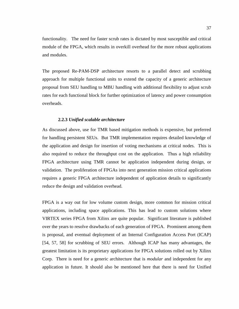
Figure 2-1 SEU in the FPGA
The Single Event Upset occurs when radiation affects the transistors that are part of the
look up table logic of the FPGAs RAM component. If the lookup table is affected by

34
radiation, it can change the bit values associated with the hardware made up of the
current FPGA design. SEU is a change of state caused by ions or electro-magnetic
radiation striking a sensitive node (area) in a micro-electronic device (Bit-Flip) [60] as
shown in the Figure 2-1. The state change is a result of the free charge created by
ionization in or close to an important node of a logic element. In these FPGAs, a
multitude of latches, also called memory cells or RAM bits, define all logic functions and
on-chip interconnects. Such latches are similar to the 6- transistor storage cells used in
SRAMs, which has proved to be sensitive to single event upsets caused by high-energy
neutrons [55, 70].
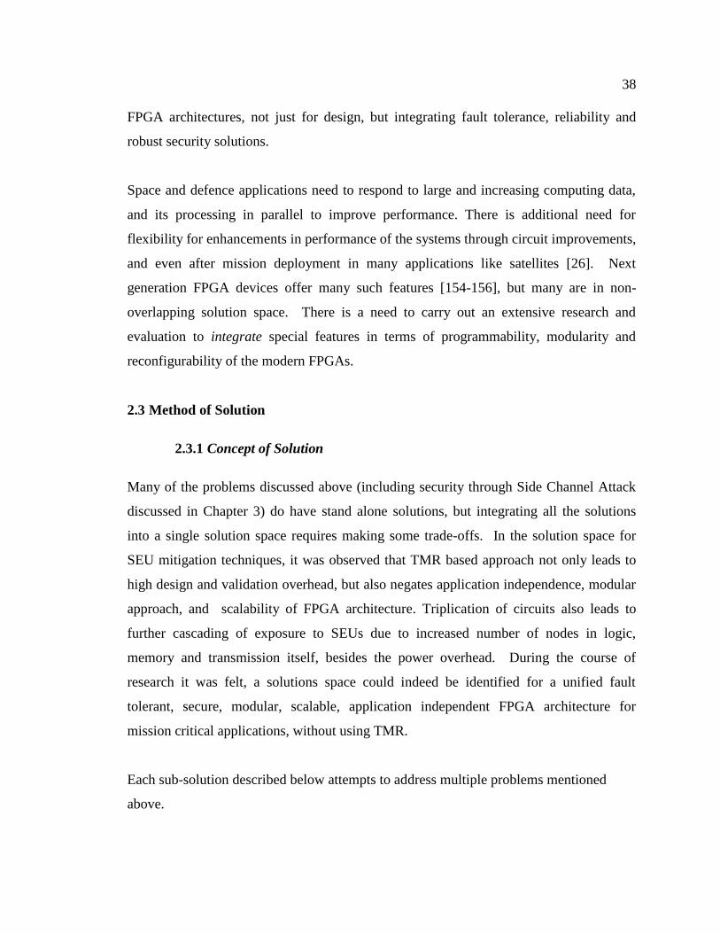
There are mainly five areas of Configurable Logic Blocks (CLB) [98-100] that are
affected by SEU as shown in Figure 2-2.
[1] Upsets in the logic (LUT)
[2] Upsets in the customization routing bits inside the CLB
[3] Upsets in the routing connecting CLBs and pins
[4] Upsets in the CLB flip-flops (flip-flops)
[5] Upsets in Block RAM
Figure 2-2 SEU Sensitive Configuration Bit Storage

35
SEU injection, Detection and correction system is designed and implemented.
SEU Mitigation
There are many possible solutions to SEU mitigation [56, 59, 60, 64, 70-73].
(1) Full Reconfiguration for Non-Critical Applications. The application device comes
to halt and is non functional during reconfiguration time.
(2) Read back with full Reconfiguration: If errors are detected, device is fully
reconfigured. During that period the functionality is affected. It is used for applications
that can tolerate errors if they are detected.
(3) Scrubbing: Scrubbing drastically increases Mean Time Between Failure (MTBF).
Continuous operation (except for SEFI) Readback / error detection can be incorporated
into scrub controller. The functionality of only the modules being scrubbed are affected.
(4) TMR + Scrubbing: For critical applications: Single FPGA with TMR and
Scrubbing can offer continuous, uninterrupted operation (except SEFI). Read back is
employed for error detection. Scrub controller detects and handles SEFIs used in critical
data processing applications (Communications, Navigation). TMR + Scrubbing is the
most common mitigation strategy for numerous missions like satellite-based DSP
modules (Image Processing, GPS Transceivers).
2.2 Detailed Problem Definition
2.2.1 Mission critical fault tolerance without TMR overhead
Commercial Of The Shelf (COTS) FPGAs are SRAM based and are susceptible to SEUs,
which may lead to failure of mission. Though there are mitigation techniques existing as
discussed earlier, but they are suffering from trade off of hardware resource utilization,
time to design, and special software tools requirements etc. SEU failures are classified as
temporary - that can be eliminated through scrubbing, and persistent - that cannot be
corrected even through repeated scrubbing attempts. A widely quoted [51] research had
recommended combination of scrubbing and TMR to handle SEU events
comprehensively. The results articulate that scrubbing is useful for resolving temporary

36
SEU, while TMR is essential for SEUs of a permanent nature that cannot be corrected
through repeated scrubbing attempts. It has been observed each method alone while
effective in reducing SEU related faults by up to 3 orders (1000 times), are unable to
eliminate failures, but a combination for both techniques is quite effective in eliminating
SEU failures for most mission-critical applications.
But this puts an additional resource burden for mission-critical fault tolerant applications.
Implementation of TMR requires triplication of circuits to enable a majority vote to
confirm validity of response of each circuit, which not only increases the physical area
and circuit latency but also adds a nearly 200% burden of power consumption. There is
an urgent need in mission-critical applications for addressing both temporary and
permanent SEU errors, without the overhead of triplication of physical area and power
consumption.
2.2.2 MBU handling
Handling Multiple Bit Upsets (MBUs) is a challenge, as MBUs could lead to
unrecoverable cascading failures, eventually requiring periodic power-down reset in
mission-critical applications. These are generally handled through aggressive scrubbing
to avoid accumulation of MBU. The TMR approach is based on a majority vote
mechanism, which presumes a very low probability of multiple local SEUs that could
otherwise overwhelm the voting mechanism of TMR approach.
There are multiple methods to optimize scrubbing resources and overhead [175-176, 226-
228]. Some of these depend on extensive scanning for errors, but selective scrubbing
only after error detection. Although an SECDED ECC can detect MBU through double
error detection (DED), actual scrubbing would slow down further scans, which cannot be
entirely compensated by higher frequency of scrubbing rates.
A single FPGA has many applications, each with many types of modules. The fault
tolerance for different modules is affected by parameters like activity factor, density, and
37
functionality. The need for faster scrub rates is dictated by most susceptible and critical
module of the FPGA, which results in overkill overhead for the more robust applications
and modules.
The proposed Re-PAM-DSP architecture resorts to a parallel detect and scrubbing
approach for multiple functional units to extend the capacity of a generic architecture
proposal from SEU handling to MBU handling with additional flexibility to adjust scrub
rates for each functional block for further optimization of latency and power consumption
overheads.
2.2.3 Unified scalable architecture
As discussed above, use for TMR based mitigation methods is expensive, but preferred
for handling persistent SEUs. But TMR implementation requires detailed knowledge of
the application and design for insertion of voting mechanisms at critical nodes. This is
also required to reduce the throughput cost on the application. Thus a high reliability
FPGA architecture using TMR cannot be application independent during design, or
validation. The proliferation of FPGAs into next generation mission critical applications
requires a generic FPGA architecture independent of application details to significantly
reduce the design and validation overhead.
FPGA is a way out for low volume custom design, more common for mission critical
applications, including space applications. This has lead to custom solutions where
VIRTEX series FPGA from Xilinx are quite popular. Significant literature is published
over the years to resolve drawbacks of each generation of FPGA. Prominent among them
is proposal, and eventual deployment of an Internal Configuration Access Port (ICAP)
[54, 57, 58] for scrubbing of SEU errors. Although ICAP has many advantages, the
greatest limitation is its proprietary applications for FPGA solutions rolled out by Xilinx
Corp. There is need for a generic architecture that is modular and independent for any
application in future. It should also be mentioned here that there is need for Unified
38
FPGA architectures, not just for design, but integrating fault tolerance, reliability and
robust security solutions.
Space and defence applications need to respond to large and increasing computing data,
and its processing in parallel to improve performance. There is additional need for
flexibility for enhancements in performance of the systems through circuit improvements,
and even after mission deployment in many applications like satellites [26]. Next
generation FPGA devices offer many such features [154-156], but many are in non-
overlapping solution space. There is a need to carry out an extensive research and
evaluation to integrate special features in terms of programmability, modularity and
reconfigurability of the modern FPGAs.
2.3 Method of Solution
2.3.1 Concept of Solution
Many of the problems discussed above (including security through Side Channel Attack
discussed in Chapter 3) do have stand alone solutions, but integrating all the solutions
into a single solution space requires making some trade-offs. In the solution space for
SEU mitigation techniques, it was observed that TMR based approach not only leads to
high design and validation overhead, but also negates application independence, modular
approach, and scalability of FPGA architecture. Triplication of circuits also leads to
further cascading of exposure to SEUs due to increased number of nodes in logic,
memory and transmission itself, besides the power overhead. During the course of
research it was felt, a solutions space could indeed be identified for a unified fault
tolerant, secure, modular, scalable, application independent FPGA architecture for
mission critical applications, without using TMR.
Each sub-solution described below attempts to address multiple problems mentioned
above.

39
1. Persistent SEU without TMR: The primary concept to handle persistent SEUs is to
use reconfiguration to swap persistently faulty resources with new ones.
2. MBU Handling: A combination of strategies is applied for MBU mitigation. First,
the FPGA is serviced through two or more SEU controllers, which enables scanning,
scrubbing, reconfiguring in parallel to reduce the chances of SEUs accumulating into
an MBU. This also helps to reduce the latency impact on the application when an
SEU is detected at run time. The same could have been achieved through increased
scrub rates, but mere duplication of SEU controllers permits many degrees of
freedom for further optimization, and enhanced reliability.
a. Different scrub rate: Each module can be assigned a unique scrub rate that
is a fraction (1/N) of fundamental scrubbing frequency. A unique N for each
module, or preferred rate of scrubbing can be dialed in at design time, or even
updated at power-up to optimize power and resource utilization depending on
the properties of the module, viz, circuit type (BRAM, DSP, ALU,
combinatorial etc.), size, activity factor, and critical index (viz SEFI or not).
b. Parallel scan, scrub and reconfigure: Multiple scans in parallel reduce the
chances of SEU accumulation. This also enables continued SEU scanning
while a particular SEU is being serviced through scrubbing by one of the SEU
controllers. By extension, this also permits running SEU scanning at a faster
rate, without interruption while one of the controllers is preoccupied by
scrubbing or reconfiguration operation.
c. Peer based monitoring of the SEU controller itself: Existence of multiple
SEU controllers enables plugging a coverage hole for SEUs in the controller
itself. Each SEU can periodically scan and scrub peer SEU controllers. In
advanced systems, confirmation of SEU occurrence by multiple peers could
be used to suppress faulty SEU detection decision by faulty SEU controller on
the victim SEU controller.
3. Unified FPGA architecture for mission critical application: A robust FPGA
architecture needs to be 1) Application independent, 2) Platform independent, 3)
Scalable for application size, and 4) Modular features for application needs.
40
a. Application independent Re-PAM DSP architecture: The application
independence level of FPGA architecture can be judged depending on the
level of pre-requisite information of the application that is needed. It can
range from being extremely sensitive to specifics of the application (and vice-
versa), hence requiring very early interaction with application design, to
requiring only a minimal set of information about the application. An
example of tight coupling of FPGA architecture with actual application is a
TMR based method of handling SEUs. In case of TMR, insertion of voting
logic is required at design time itself. This composite design needs to be
validated, with additional vectors to test the insertion of TMR logic into
application design. The other extreme is the proposed Re-PAM-DSP
approach that is a super-position of fault tolerance and security features
without requiring any knowledge of application itself. In this case, handling of
SEUs and MBUs through scrubbing and reconfigurations interacts with the
application through scans for detection phase, and scrubbing or modularized
reconfiguration for correction phase. The Re-PAM-DSP architecture does not
need to dig deeper into application details. Hence the search for alternative to
TMR based solution was imperative for application independent, mission-
critical fault tolerant and secure Re-PAM-DSP FPGA architecture.
b. Platform independent Re-PAM-DSP architecture: Reconfiguration
techniques have become essential for mission-critical fault tolerant FPGA
architectures. But the specifics of the implementation of reconfiguration are
proprietary to platform of manufacturers like Xilinx (Virtex series [57-60])
and Atmel (AT40K series [30]). The proposed fault tolerant Re-PAM DSP
architecture is independent of platform specifics, and open to newer versions
of reconfiguration platforms of future.
c. Re-PAM-DSP architecture scalable for application size: A FPGA
architecture’s impact on various applications is measured along metrics like
size overhead, activity factor, throughput time or latency. The complexity of
implementing fault tolerant and security features of FPGA architecture could

41
have unacceptable cost on any, or many of these metric. The choices of Re-
PAM-DSP architecture preferred a super-position approach to make
implementation cost (along each metric) scalable with application size.
d. Modular Re-PAM-DSP architecture: The modularity of Re-PAM-DSP
architecture is at three levels viz. basic fault tolerance, advanced mission
critical, and security needs.
i. The susceptibility to SEU occurrence has a wide range depending on
deployment of application from outer space to ground based
applications. The basic fault tolerance features of Re-PAM-DSP
architecture allow user programmable knobs for various combinations
of scan, scrub and reconfiguration. This flexibility also percolates from
application level, down to module level or even finer granularity.
ii. The criticality of the application or a module within the application,
dictate choices like level of fault tolerance and security. The criticality
and impact of each SEU also depends on the application. In extreme
mission critical applications, SEU controllers in Re-PAM-DSP
architecture could be scanned at faster rates, and even multiple scans
by peer SEU controllers to reduce the probability of fault occurrence
in SEU controller itself.
iii. The runtime insertion of SCA defense blocks in proposed Re-PAM-
DSP architecture can be varied for number of instances and
occurrences to enhance the randomization of the power signature of
device under attack.
2.3.2 Architectural Overview:
An ICAP based scrubber design is used as architectural platform. A typical soft core
processor-based Partial Reconfiguration (PR) system is implemented as shown in Figure
2-3, and detailed description is in Appendix-A (Partial reconfiguration)

42
Figure 2-3 Block Diagram of Self Correcting System
It consist of Microblaze, SEU controller consist of SEU Macro along with ECC and
ICAP Primitives, Configuration memory, SysACE interface , UART and bus macros for
interfacing with partial reconfiguration modules. The architecture and design of SEU
controller is in the following section 2.3.3.
The UART is used for interfacing the test platform with host PC. The software for partial
reconfiguration is written in C. The software makes use of Xilinx ISE, Embedded
Development Kit (EDK) and Software Development Kit (SDK).
The Re-PAM-DSP architecture proposes multiple SEU controller blocks with respective
MicroBlaze processors for parallel SEU handling, MBU handling, and peer based SEU
coverage of each SEU controller as shown in Figure 2-4, and described in detail below.

43
Figure 2-4 Block Diagram of Multiple SEU controller implementation
Figure-2-4(a) indicates each application and its modules are assigned a unique N, so that
it is scanned and scrubbed at a fraction (1/N) of the fundamental scrubbing frequency.
This unique N for each module can have a default value at design time, but can also be
updated during any reconfiguration or power-up to further optimize power consumption
and resource utilization depending on the properties of the module, vis. Circuit type
(BRAM, DSP, ALU, combinatorial etc), size, activity factor, and critical index (viz. SEFI
or not). Flexibility exists to update this N post deployment, based on historical SEU data
collected on each component. As shown in Figure 2-4(b) each module can be serviced by
any SEU controller, unless it is already being scanned, scrubbed, or reconfigured. When
one SEU controller is engaged in SEU scrubbing or reconfiguration of a particular
module, the scanning of the rest modules can continue uninterrupted, which significantly
reduces the latency in scanning for next SEU occurrence, thereby reducing the
probability of MBU occurrence. Figure 2-4(c) shows there is a coverage hole in SEU
controller proposal – how to scan for SEUs in the SEU controller itself. This is when
SEU occurrences in each SEU controller are managed by its peer SEU controllers. The
functionality of an SEU controller and its respective MicroBlaze processor is classified as
critical SEFI. The voting is based on confirmation by all other peer SEU controllers,
thereby ignoring decisions by a faulty SEU controller, imposed on a healthy SEU
controller being scanned. Thus Re-PAM-DSP architecture has a set of inter-locking
SEFI fault coverage without coverage holes, to create a truly SEU self healing system.

44
Figure 2-5 extends the concept of multiple SEU controllers to show robustness of Re-
PAM-DSP architecture as scalable and independent of application properties, relatively
independent of platform choices, and permitting a modular choice of fault tolerant level
and security features. Figure 2-5(a) shows when an SEU controller is engaged in SEU
scrubbing / reconfiguring, a peer SEU controller can continue scanning the rest of design.
Thus the existence of multiple SEU controllers avoids any upper limit on the fastest
scan/scrub/reconfigure rate for worst combination of SEU occurrence, application size,
and criticality of fault tolerance. As discussed extensively, Re-PAM-DSP is a hands-off
approach to application, with independent choice of scrub rates. Selective scrub rates at
such granularity also avoid burden of worst casing to fastest scrub rate for the weakest
blocks in SOC. Figure 2-5(b) shows Re-PAM-DSP can be easily adapted for any
platform that supports some form of reconfiguration. Modularity of feature stacking is
illustrated in figure 2-5(c). Choices like 1) SEU controller count, scrub and
reconfiguration rates, 2) SCA defence based on flexible size, physical occurrence,
frequency of insertion, of randomizer circuit block, give unprecedented freedom to dial
for target combination of fault tolerance and security level.

45
Figure 2-5 Robustness of Re-PAM-DSP across application, platform and features
2.3.3 Implementation of SEU Controller Macro
Implementation of SEU Controller Macro and its basic architecture is shown in Fig. 2-7
and 2-8.

46
Figure 2-6 ICAP based internal reader
Figure 2-7 SEU Controller Macro Interface
Design and Implementation of SEU Controller Macro, its internal primitives like ECC
and ICAP along with its operation is also articulated in Appendix-C.
SEU Monitor system consists of SEU controller macro and monitor program [106, 107].
SEU monitor system is implemented using SEU controller MACRO, Microblaze
processor and SEU monitor software.

47
SEU monitor system is used to emulate the SEU by means of fault injection, detection
and correction mechanism. Emulation of SEU has been implemented. Finally the user
design, SEU Monitor system, Soft core processor (MicroBlaze) [155] and Partial
reconfiguration have been integrated to get the self healing system on the Re-PAM-DSP
Platform as shown in Fig. 2-8.
Figure 2-8 Unified Architecture Platform
An overview of existing SEU detection mechanisms using FPGA primitives and
configuration memory can be found in APPENDIX-C. It reviews structure of a
configuration memory frame. ECC is enforced through primitives like Syndrome Bits
and Error Codes. The detection mechanism of errors is carried out using read-back CRC,
while correction is done through ICAP primitives, and SEU controller macro. The SEU
Monitor System hardware platform and software are detailed in APPENDIX-D. The
SEU monitor system consists of a soft core processor and SEU controller macro. It is
connected to PC through UART for external monitoring of SEU and SEU emulation. A

48
sample GUI screen shot for fault emulation and its corresponding results are also
included in APPENDIX-D.
Figure 2-9 SEU Controller MONITOR System
Along with this macro, the SEU monitor system which is created to handle the
functionality of this macro is shown in Figure 2-9. In this method, the soft processor is
required to monitor and to control the functionality of SEU controller macro, and to
provide the user interface. In this work, MicroBlaze is used as a soft core processor and
UART (RS232) as a standard IO of the entire system to provide the interface for the user.
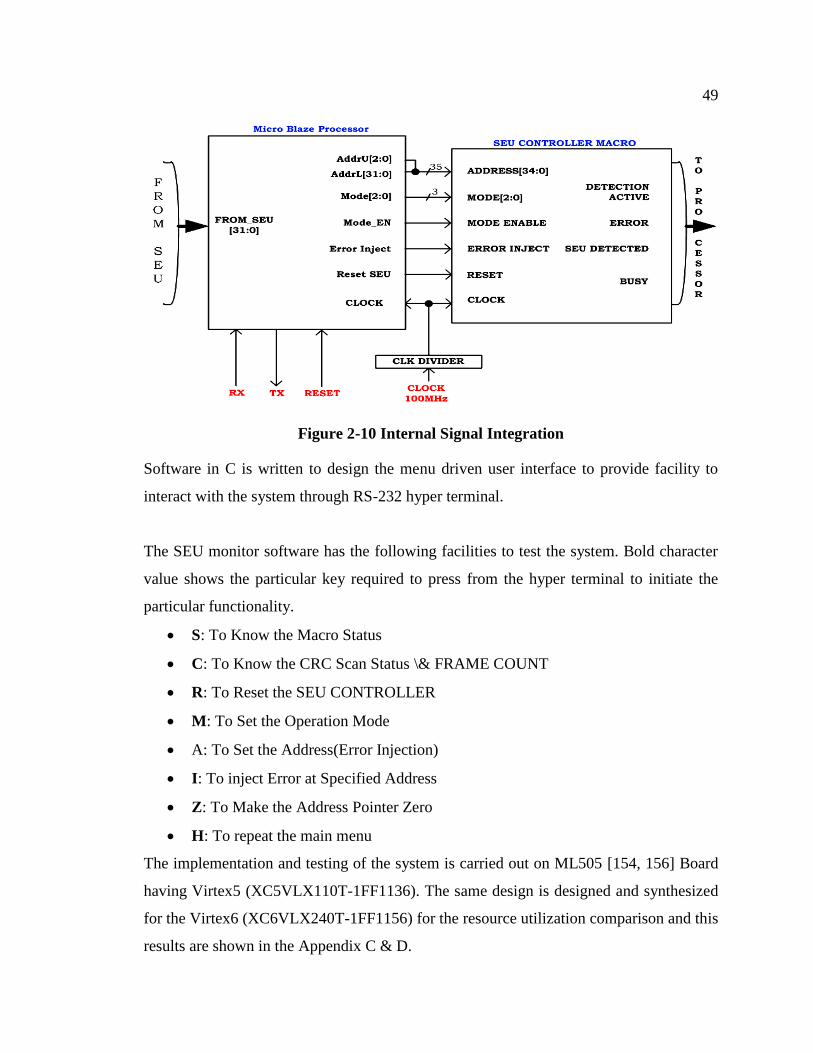
Figure 2-10 show the internal signal connection of the monitor and the controller macro.
Design of SEU monitor system is created using Xilinx's EDK [61, 62, 120, 123- 127] and
ISE software to handle the functionality of this macro. Figure 2-10 shows port mapping
of the system created in EDK.
49
Figure 2-10 Internal Signal Integration
Software in C is written to design the menu driven user interface to provide facility to
interact with the system through RS-232 hyper terminal.
The SEU monitor software has the following facilities to test the system. Bold character
value shows the particular key required to press from the hyper terminal to initiate the
particular functionality.
S: To Know the Macro Status
C: To Know the CRC Scan Status \& FRAME COUNT
R: To Reset the SEU CONTROLLER
M: To Set the Operation Mode
A: To Set the Address(Error Injection)
I: To inject Error at Specified Address
Z: To Make the Address Pointer Zero
H: To repeat the main menu
The implementation and testing of the system is carried out on ML505 [154, 156] Board
having Virtex5 (XC5VLX110T-1FF1136). The same design is designed and synthesized
for the Virtex6 (XC6VLX240T-1FF1156) for the resource utilization comparison and this
results are shown in the Appendix C & D.

50
Table 2-1 Resources utilization for SEU Monitor System
Device Virtex XC5VLX110T-1ff1136 Virtex-6 XC6VLX240T-1ff1156
Resource Available Used Utilisation Available Used Utilisation
Total Number Slice
Registers
69120 2599 3.76% 301440 155 0.05%
Number of LUTs 69120 2220 3.76% 150720 214 0.14%
Number of bonded
IOBs
640 4 0.62% 600 4 0.66%
Number of Block
RAM/ FIFO
148 66 44.59% 416 2 0.05%
Number of BUFG/
BUFGCTRLs
32 4 12.5% 32 2 6.25%
Number of ICAP
VIRTEX's
2 1 50% 2 1 50%
Number of FRAME
ECC VIRTEX
1 1 100% 1 1 100%
The SEU controller macro and reference design can emulate an SEU by deliberately
injecting an error into the FPGA configuration so that its subsequent detection and
correction can be confirmed.
2.3.4 Self Healing system
Finally the all the modules have been integrated into one system called Self correcting/
healing System [45]. The SEU controller macro has been integrated into the previously
created Self reconfigurable system. The block diagram of the self correcting system is
shown in Figure 2-11.

51
Figure 2-11 Block Diagram of Self Correcting System
The concept of the final design is like this - the user design / testcase is configured on the
FPGA. The self healing platform is superposed on the ported application. Here the SEU
monitor system injects the faults and detects the effect of fault on functionality of the
application. The testcases used are MAC, ALU, FIR, CoProcessor and Processor. The
results of fault emulation are shown in table 2-2.
2.4 Implementation Results
This is the RTL view of SEU monitor system.

52
Figure 2-12 RTL of Self Correcting System
Figure 2-12 shows the RTL of Self Correcting System which includes the controller
macro and soft core processor.
Table 2-2 Fault Emulation results on Re-PAM DSP Architecture Platform
Scenario MAC ALU FIR (16Tap) Co-Processor Processor
All Injected Random faults 8000 8000 10000 10000 10000
Fault that affected the system 145 180 257 415 531
Faults recovered using scrubbing
102 115 142 308 426
Faults recovered using Parallel Scrubbing
132 162 245 397 513
Unrecovered faults 13 18 12 18 18

53
Table 2-2 presents the results of fault emulation applied to various test cases as listed
including MAC, ALU, 16 tap FIR filter, co-processor and soft core processor like
Microblaze and LEON-3. Random single bit flip faults were injected using SEU monitor
system after configuring the Re-PAM-DSP for specific application. The number of
random faults varied from 8000 to 10,000 depending on the application ported in the
platform. For example we will analyze the results for MAC application. 8000 faults are
injected. 145 faults affected the operation of the application/ computing. 102 faults were
detected and corrected using SEU macro controller mechanism. The remaining faults
caused the error in the functionality. The proposed new approach of parallel scrubbing
using multiple instantiation of SEU Macro (Here two SEU macro were used) is applied.
Using this technique, 132 faults are recovered and only 13 faults could not be recovered.
Looking to all other application it is observed that parallel scrubbing offers high
achievement in reducing the no of faults unrecovered. It can be further improved and
reduce the no of unrecovered fault by changing the scrubbing rate and multiple SEU
macro at the cost of area overhead.
We now discuss the results of Re-PAM-DSP for handling Multiple Bit Upsets (MBUs).
MBUs are generally handled through aggressive scrubbing to avoid accumulation of SEU
that would otherwise overwhelm the voting mechanism of Triple Modular Redundancy
(TMR) approach.
The Proposed (Re-PAM-DSP) architecture instead resorts to a parallel detect and
scrubbing of multiple functional units to extend the capacity of an existing SEU handling
mechanism of SRAM Based FPGAs to MBU handling, thereby avoiding the need for a
TMR based intrusive fault tolerant system for persistent SEUs.
Now a days, we have high performance FPGAs available in terms of resources, speed,
computing power, interface connectivity. Here the FPGA resource layout can be fine
grain or coarse grain architecture depending upon the requirement of applications. The
application deployed can have multiple functional blocks. Each functional block can have
54
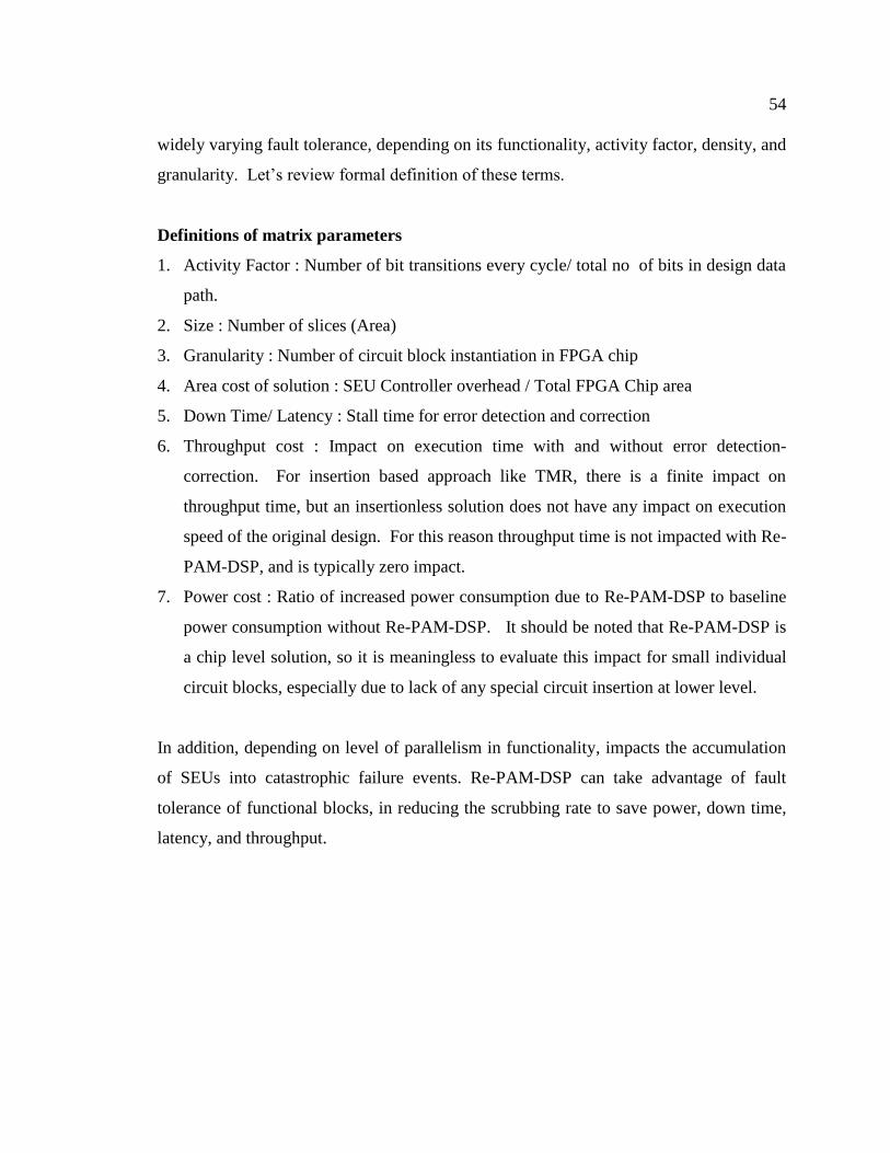
widely varying fault tolerance, depending on its functionality, activity factor, density, and
granularity. Let’s review formal definition of these terms.
Definitions of matrix parameters
1. Activity Factor : Number of bit transitions every cycle/ total no of bits in design data
path.
2. Size : Number of slices (Area)
3. Granularity : Number of circuit block instantiation in FPGA chip
4. Area cost of solution : SEU Controller overhead / Total FPGA Chip area
5. Down Time/ Latency : Stall time for error detection and correction
6. Throughput cost : Impact on execution time with and without error detection-
correction. For insertion based approach like TMR, there is a finite impact on
throughput time, but an insertionless solution does not have any impact on execution
speed of the original design. For this reason throughput time is not impacted with Re-
PAM-DSP, and is typically zero impact.
7. Power cost : Ratio of increased power consumption due to Re-PAM-DSP to baseline
power consumption without Re-PAM-DSP. It should be noted that Re-PAM-DSP is
a chip level solution, so it is meaningless to evaluate this impact for small individual
circuit blocks, especially due to lack of any special circuit insertion at lower level.
In addition, depending on level of parallelism in functionality, impacts the accumulation
of SEUs into catastrophic failure events. Re-PAM-DSP can take advantage of fault
tolerance of functional blocks, in reducing the scrubbing rate to save power, down time,
latency, and throughput.
55
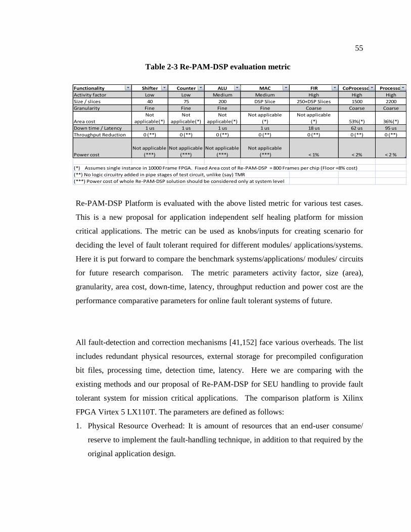
Table 2-3 Re-PAM-DSP evaluation metric
Functionality Shifter Counter ALU MAC FIR CoProcessor Processor
Activity factor Low Low Medium Medium High High High
Size / slices 40 75 200 DSP Slice 250+DSP Slices 1500 2200
Granularity Fine Fine Fine Fine Coarse Coarse Coarse
Area cost
Not
applicable(*)
Not
applicable(*)
Not
applicable(*)
Not applicable
(*)
Not applicable
(*) 53%(*) 36%(*)
Down time / Latency 1 us 1 us 1 us 1 us 18 us 62 us 95 us
Throughput Reduction 0 (**) 0 (**) 0 (**) 0 (**) 0 (**) 0 (**) 0 (**)
Power cost
Not applicable
(***)
Not applicable
(***)
Not applicable
(***)
Not applicable
(***) < 1% < 2% < 2 %
(*) Assumes single instance in 10000 Frame FPGA. Fixed Area cost of Re-PAM-DSP = 800 Frames per chip (Floor =8% cost)
(**) No logic circuitry added in pipe stages of test circuit, unlike (say) TMR
(***) Power cost of whole Re-PAM-DSP solution should be considered only at system level
Re-PAM-DSP Platform is evaluated with the above listed metric for various test cases.
This is a new proposal for application independent self healing platform for mission
critical applications. The metric can be used as knobs/inputs for creating scenario for
deciding the level of fault tolerant required for different modules/ applications/systems.
Here it is put forward to compare the benchmark systems/applications/ modules/ circuits
for future research comparison. The metric parameters activity factor, size (area),
granularity, area cost, down-time, latency, throughput reduction and power cost are the
performance comparative parameters for online fault tolerant systems of future.
All fault-detection and correction mechanisms [41,152] face various overheads. The list
includes redundant physical resources, external storage for precompiled configuration
bit files, processing time, detection time, latency. Here we are comparing with the
existing methods and our proposal of Re-PAM-DSP for SEU handling to provide fault
tolerant system for mission critical applications. The comparison platform is Xilinx
FPGA Virtex 5 LX110T. The parameters are defined as follows:
1. Physical Resource Overhead: It is amount of resources that an end-user consume/
reserve to implement the fault-handling technique, in addition to that required by the
original application design.

56
2. Throughput Reduction: Faults may occur in PLBs that are located along a critical
timing path of the application. Reconfiguring the application to function correctly in
the presence of such a fault may extend the length of the critical path, thereby
increasing signal propagation delay.
3. Detection Latency: It specifies the amount of time required for the fault-handling
method to detect and/or locate the fault.
4. Recovery Time: The recovery time of a fault-handling method is the time required to
restore complete functionality to the application implemented on the FPGA, as
measured starting from the time the fault is detected and/or located.

57
Table 2-4 Re-PAM-DSP Overhead-Related Metrics
Metrics
Physical Resource Overhead
Throughput Reduction
Detection Latency
Recovery time for single fault
Logic Inter-Connect
Ap
iori
Res
ou
rce
of
Allo
cati
on
Spar
e
Co
nfi
gura
tio
ns
Fine-grained 2-10% of application
None 14-45% Not Addressed
{44us-64ms}
Functional-unit
partitioning
200% of Application
Not Provided Negligible None
Coarse-grained
40% of FPGA 0-14% Not Addressed
Place&Route + s
Spar
e
Res
ou
rces
Sub-PLB Spares
8-20% of Application
None Not Provided Not Addressed
Place&Route + 64ms
PLB Spares 1-41% of FPGA
9-5-% of Application
0-15% Not Addressed
Place + 64ms
Dyn
amic
Rec
ove
ry P
roce
sses
Off
line
Rec
ove
ry
Incremental Rerouting [ 72 ]
Subset of unutilized Resource on FPGA
2-35% Not Addressed
{2-12s} + 64ms
GA Recovery [ 107 ]
Subset of unutilized Resource on FPGA
Intermediate Not Addressed
Unbounded
Augmented GA Recovery [ 141 ]
Subset of unutilized Resource on FPGA
Intermediate 12 generations
38% decrease form GA Recovery
On
line
Rec
ove
ry
TMR w/Single Module
Recovery [65]
200 % of Application
Intermediate Negligible None
Online BIST [70 ]
4-11% of FPGA 0-16% 0-17s None
Our Proposal 8-15 % of FPGA resources
None 0-2 % us to 10’s of ms
us to ms < 1 ms for multi SEU Macro
Considering the Re-PAM-DSP Architecture as solution to online self healing platform we
can compare it with TMR and online BIST. It is superior in all respect of listed metric. It
can further be improved with increased number of parallel scrubbing module
instantiation. This is true self healing where the detection time and correction time can be
brought to 10’s of us using advanced scrubbing.

58
This principle can seamlessly scale to inter-chip scrubbing rates also.
2.5 Summary
A proposed approach to combat SEU through Self healing System using the SEU monitor
system is presented here. It uses the soft core processor and SEU controller macro. The
SEU controller macro basically uses the ICAP and FRAME_ECC primitives of Xilinx
FPGA. This is capable of injection, detection and correction the of single-bit SEU errors
manually and automatically when operated in automatic mode for System on FPGAs. It is
also capable of injection and detection of the double-bit errors in the FPGA configuration
memory. For the easy access to the System, user interface is created, which can
communicate through RS-232 and hyper terminal program. The design can be easily
integrated in any existing user design on FPGA, with minimal resource overhead of
approximately 5% for detection and correction of single bit errors using the presented
approach of self healing.
Recommended


![CEN TR 13480-7_2002 - Metallic Industrial Piping - Part 7 [Eng]](https://img.dokumen.tips/doc/110x75/56d6c0481a28ab301699b9f0/cen-tr-13480-72002-metallic-industrial-piping-part-7-eng.jpg)
