Canned Cycles
for
Lathe & Milling
1

2
Canned Cycles for Lathe :
G71
G72
G70
G73
G75
G76
G81

3
G71 Turning Cycle :
G71 turning cycle is used for rough-material removal from a CNC lathe component. G71 turning
cycle makes large diameter cutting easy. Cutting can be done in simple straight line or a complex
contour can also be machined very easily.
Through G71 turning cycle parameters CNC machinists can control
Depth of cut.
Retract height.
Finishing allowance in x-axis and z-axis.
Cycle cutting-feed, spindle speed.

4
Continue….
Programming syntax :-
G71 U… R…G71 P… Q… U… W… F… S…
Block Parameter Description
First Block U Depth of cut
R Retract height
Second Block P Contour start block number
Q Contour end block number
U Finishing allowances in x-axis
W Finishing allowances in z-axis
F Feed rate during G71 cycle
S Spindle speed during G71 cycle

5
Continue….
G71 Turning Cycle Overview :
G71 turning cycle cuts the whole contour repeatedly which is given in P Q blocks.
Depth of every cut can be controlled by first-block U value.
Second-block U W are the finishing allowances which can be given if you want to make a finish
cut with G70 finishing cycle.
F is cutting feed and S is spindle speed (given in second-block) which are used during G71 turning
cycle.
The F and S given inside P Q block will not be used during G71 turning cycle, they are used with
G70 finishing cycle if later called.

6
Continue….
G71 Turning Cycle Working :
N60 G71 U10 R10N70 G71 P80 Q90 U3 W0 F0.25N80 G00 X60N90 G01 Z-75

7
Continue….
When G71 turning cycle is run the whole operation will be done in following sequence,
First-cut
1 – Tool will move in x-axis U (depth of cut)
deep with programmed feed from starting-
point.
2 – Tool will travel with feed in z-axis
(destination point in z-axis is given in P Q
blocks )
3 – Tool rapidly retracts R amount in both x-
axis and z-axis (at 45 degrees).
4 – Tool rapidly travel in z-axis to start-point
Later-cuts
5 – Tool rapidly moves to last cut depth.
6 – Tool moves with feed in x-axis U deep
(first-block U depth of cut).
7 – Tool with feed moves in z-axis (destination
point given in P Q blocks).
8 – Tool rapidly retracts in x-axis and z-axis R
amount (45 degrees).
9 – Tool rapidly moves to start-point only in z-
axis.

8
G70 Finishing Cycle :
If you programmed G71 turning cycle with finishing allowances then that finish allowances can be
removed with G70 finishing cycle.
G70 finishing cycle repeats the whole contour the G71 way, but in just one cut removing the
finishing allowances.
Why Use G70 Finishing Cycle :
As material can be removed with G71 turning cycle, but if you want a different cutting feed and
spindle speed for the last cut, then it is recommended that you use G70 finishing cycle.
G70 finishing cycle use F and S values which are given inside P Q programmed blocks. (G71 use F
S values which are given inside G71 second block.)

9
G72 Facing Cycle :
Programming syntax :-
G72 W… R…G72 P… Q… U… W… F… S…
Block Parameter Description
First Block W Depth of cut
R Return value after a cut is complete
Second Block P Contour start block number
Q Contour end block number
U Finishing allowances in x-axis
W Finishing allowances in z-axis
F Feed rate during G71 cycle
S Spindle speed during G71 cycle
10
Continue….
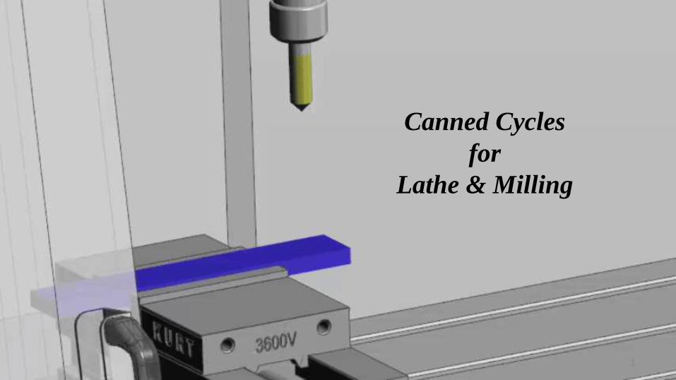
Fanuc G72 Facing Cycle Example :
N5 G00 X65 Z42N6 G72 W2 R2N7 G72 P8 Q9 U0 W0 F0.3N8 G00 Z30N9 G01 X20

11
G73 Pattern Repeating Cycle :
Programming syntax :-
G73 U… W… R…G73 P… Q… U… W… F…
Block Parameter Description
First
Block
U Escape distance and direction in X axis (radius value).This
is the amount of material which will be cut in x-axis.
W Escape distance and direction in Z axis. This is the amount
of material which will be cut in z-axis.
R Number of divisions. The number the contour will be
repeated.
Second
Block
P Start sequence No
Q End sequence No.
U Finishing allowance in x-axis.
W Finishing allowance in z-axis.
F Cutting Feed rate (during G73 canned cycle).

12
G73 Pattern Repeating Cycle Program Example :
N10 G50 S2000 T0300 G96 S200 M03 G00 X35.0 Z5.0 T0303 G00 Z0 G01 X-1.6 F0.2 G00 X70.0 Z10.0 G73 U3.0 W2.0 R2 G73 P12 Q16 U0.5 W0.1 F0.25 N12 G00 G42 X20.0 Z2.0 G01 Z-10.0 F0.15 G02 X40.0 Z-20.0 R10.0 G01 Z-30.0 G00 X60.0 Z-50.0 N16 G40 U1.0 G70 P12 Q16 G00 X200.0 Z200.0 T0300

13
G75 Canned Cycle Grooving :
Programming syntax :-
G75 X…G75 X… Z… P… Q… R…
Block Parameter Description
First
Block
X Return amount
Second
Block
X Groove Depth
Z Last groove position in z-axis
P Peck increment in x-axis
Q Stepping in z-axis
R Relief amount at end of the cut

14
G75 Canned Cycle Grooving CNC Programming Example
N10 G50 S500 T0100 N20 G97 S400 M03 N30 G00 X90.0 Z1.0 T0101 N40 G00 X82.0 Z-60.0 N50 G75 R1.0 N60 G75 X60.0 Z-20.0 P3000 Q20000 F0.1 N70 G00 X90.0 N80 G00 X200.0 Z200.0 T0100 N90 M30

15
G76 Threading Cycle :
Programming syntax :-
G76 P010060 Q100 R0.05G76 X30 Z-20 P1024 Q200 F2 R...
Block Parameter Description
First
Block
P P actually consists of multiple values which control the thread behavior,
01 : Number of spring passes or spring cuts.
00 : Thread run out at 45 degree
60 : Flank angle or Thread angle
Q Depth of normal cut ( these values are given in hundreds, so the depth of cut will be 0.1 )
R Depth of Last or Finish cut

16
Continue….
Block Parameter Description
Second
Block
X The end value in x-axis
Z The end value in z-axis
P Thread depth ( as radius value )
Q Depth of first cut
F Thread Pitch
R Thread Taper ( If R value is zero or not specified, straight thread cutting is performed )

17
G76 Thread Cycle Example :
N10 T3 N20 G97 S800 M03 N30 G00 X30 Z5 T0303 N40 G76 P021060 Q100 R100 N50 G76 X18.2 Z-20 P900 Q200 F1.5 N60 G00 X50 Z-20 N70 G76 P021060 Q100 R100 N80 G76 X38.2 Z-52 P900 Q200 FI .5 N90 G00 X200 Z200 N100 M30

18
Canned Cycles for Milling :
G81
G82
G83
G73
G84
G74

19
G81 Drilling Cycle :
Programming syntax :-
G81 X... Y... Z... R... K... F...
Parameter Description
X Hole position in x-axis.
Y Hole position in y-axis
Z Depth, tool will travel with feed to Z-depth starting from R plane
R Position of the R plane.
K Number of cycle repetitions (if required)
F Feed rate
20
Continue….
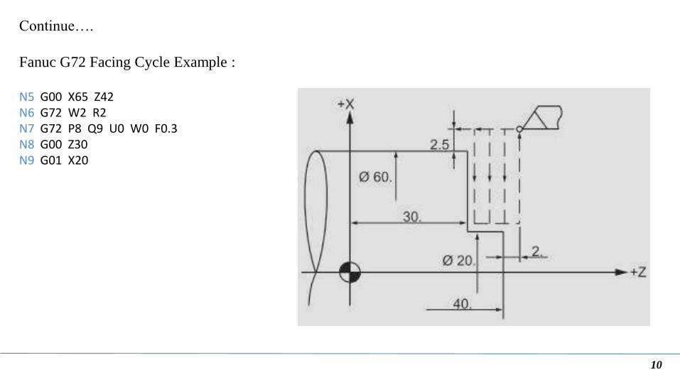
G81 Cycle Working :-
Here is briefly described how G81 drilling
cycle operates,
1. Rapid traverse to the specified x,y axis
position (drilling position).
2. Rapid traverse to the R plane position.
3. Drilling with specified Feed from R-plane
position to Z-depth position.
4. Rapid traverse to Initial level or R-plane
depends on G98, G99 modes.

21
Continue….
G98 G99 Modes
After completing drilling depth the return is
made with Rapid feed, the return height can be
controlled through using G98 or G99.
G98 Drill will return to the Initial level
G99 Drill will return to R-plane.
G98, G99 can be used multiple times during
G81 drilling cycle.

22
Continue….
Working Examples :
N10 T1 M06N20 G90 G54 G00 X30 Y25 N30 S1200 M03 N40 G43 H01 Z5 M08 N50 G81 Z-10 R2 F75 N60 X80 Y50 N70 G80 G00 Z100 M09 N80 M30

23
Continue….
G98 G99 Example :-
N10 M06 T1 N20 G90 G00 X12.5 Y10 Z12 S1000 M03 N30 G99 G81 X12.5 Y10 Z-17 R2 F75 N40 Y30 N50 G98 X57.5 N60 G99 Y10 N70 G91 G80 G28 X0 Y0 Z0 M05 N80 M30

24
Continue….
Repeat Drilling Example :-
T1 M6 G00 G90 G40 G21 G17 G94 G54 X0 Y0 S1000 M03 G43 H1 Z100 Z3 G81 G99 G91 X20 Y20 R3 Z-20 K3 F100 M08 G80 G00 G90 Z100 M30
25
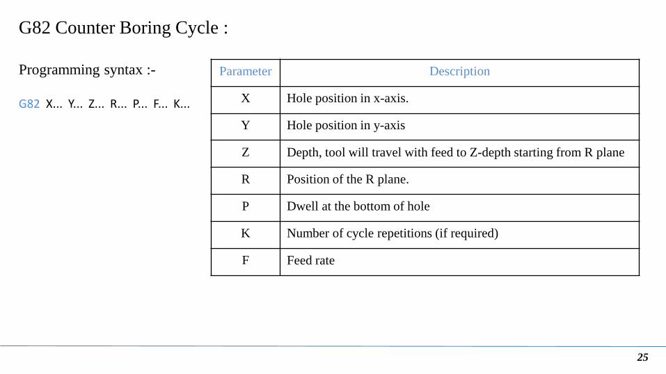
G82 Counter Boring Cycle :
Programming syntax :-
G82 X... Y... Z... R... P... F... K...
Parameter Description
X Hole position in x-axis.
Y Hole position in y-axis
Z Depth, tool will travel with feed to Z-depth starting from R plane
R Position of the R plane.
P Dwell at the bottom of hole
K Number of cycle repetitions (if required)
F Feed rate

26
Continue….
Working Example :-
N10 T1 M06 N20 G90 G54 G00 X30 Y25 N30 S1200 M03 N40 G43 H01 Z5 M08 N50 G82 Z-10 R2 P1000 F75 N60 X80 Y50 N70 G80 G00 Z100 M09 N80 M30

27
Recommended