BASIC PUMP OPERATIONS
INSTRUCTOR GUIDE
Approved by
AL
Fire Service Training and Education Program a component of the CALIFORNIA FIRE SERVICE TRAINING AND EDUCATION SYSTEM
FIRST EDITION

BASIC PUMP OPERATIONS
INSTRUCTOR GUIDE
Approved by
AL
Published by
California State Fire Marshal California Fire Service Training and Education System 7171 Bowling Drive, Suite 600 Sacramento, CA 95823

FSTEP
The FSTEP series is designed to provide beginning and volunteer fire
fighters with basic hands-on training in fire ·fighting, extrication, rescue, and
emergency care. Course hours are designed for weekend and/or evening
presentations. Delivery may be custom tailored to each department's
specific needs. Upon successful completion of each course, a California
State Fire Marshal's certificate of completion will be issued by the
instructor.
This course was developed to assist in the delivery of Pump Operations for
the Volunteer Fire Fighter. This Instructors Guide is only a guide, please
use the materials in it as you need. It was developed for your use.

ACKNOWLEDGEMENTS
The development of the material contained in this guide was coordinated by the Training Division of the California State Fire Marshal's Office and approved by the State Training and Education Advisory Committee (STEAC) and the State Board of Fire Services (SBFS). This curriculum is appropriate for fire service personnel and for personnel in related occupations who are pursuing one or more of the certification programs.
Ronny J. Coleman, Chief California State Fire Marshal
Ed Seits Deputy Cbief, State Fire Marshal, Training Division
The material contained in this document was compiled and organized through the cooperative effort of numerous professionals within, and associated with, the California Fire Service.
We acknowledge the Waterous Company and the California Department of Forestry and Fire Protection for their contributions to this document.
We gratefully acknowledge the following individuals who served as the principal developers for this document.
MEMBERS OF THE FIRE SERVICE
Michael Ridley, Training Specialist Ill Sacramento County FPO
Jess Smith, Engineer Willows Fire Department
James Eastman, Division Chief Sacramento County FPO
Loren Abbott, Engineer Sacramento County FPO
Members of the Driver Operator Curriculum Development Workshop

INTRODUCTION
This publication is intended to serve as an Instructor's Guide. The Guide has been designed to include lesson plans, assignment sheets and information sheets. Suggested application methods have been identified throughout each lesson for the instructors' use at appropriate times during their presentation.
The success of the students in this course depends greatly on the instructors' conformance to the student behavioral objective prescribed at the start of each lesson. the remaining portion of the lesson plan has been designed to serve only as a guide; and as such, should not preclude instructors from adapting their lesson plans to best meet the needs of the students.
Group activities and direct application of the skills addressed in this curriculum are essential to the success of this course. The various forms, guidelines and procedures are examples only and are included as a resource for use where appropriate.
Each page within the Instructor Guide is identified in the upper left corner with either of two headings (Instructor Guide or Instructor Info) that denote the function of the material contained on the page.
INSTRUCTOR GUIDE
Material on these pages is intended to serve as an outline of instruction in lesson plan form. For each topic identified in the course outline, a lesson plan has been developed that contains: a level of instruction, time frame, student behavioral objective, references, materials needed and lesson content.
• LEVEL OF INSTRUCTION. Identifies the instructional level which the material was designed to fulfill. Obviously, the instructor has the latitude to increase the level based on time available, local conditions and the students' apperceptive base.
• TIME ALLOTMENT. The minimum, estimated duration required for "in class" presentation based on a 36-40 hour, five day course.
• STUDENT BEHAVIORAL OBJECTIVE. The behavioral objective is a statement of the student's performance desired at the end of instruction. The instructor must make sure that enough information is given in the presentation to enable the student to perform according to the goal.
• REFERENCES. These are the speci'fic references that the instructor must study to teach the lesson -- books, manuals, bulletins, scripts, visual aid utilization plans and the like -- including page numbers.
• MATERIALS NEEDED. This should be a complete list of everything the instructor will need to present the lesson, including handout materials, visual aids, quizzes, examinations, answer sheets and so on. If the lesson requires the instructor to make any visual preparation, this should be stated.
• LESSON CONTENT. Includes information utilized in the 4 Step Method of Instruction. Two different terms are used to identify material that appears in the application column of the lesson plan.
Discuss QI Review. Identifies potential questions or discussion items that the instructor may choose to utilize during the presentation of the lesson to gain feedback and monitor student progress. Although material is included here, instructors are encouraged to develop their own material.
Instructor~- Alerts the instructor of a possible method of conducting instruction, points out items to be covered within discussion, identi'fies student exercises and references pages in the student manual.
INSTRUCTOR INFO
Material on these pages is also found in the Student Manual. They contain information related to specific topics within the curriculum in the form of information sheets, assignment sheets, charts and forms.
CONSIDERATIONS FOR LESSON DELIVERY
With the exception of simulation equipment and materials, the information within the course is designed for presentation without the use of commercially or locally developed films, video tapes and slides. This does not mean that the instructor is prohibited from employing audio visual aids during the course. The instructor is encouraged to utilize any a/v which will assist in the presentation of material and attainment of performance goals.
The students should be required to review the material previously covered and scan the material in upcoming class sessions. This will facilitate topic development and provide the instructor with a more receptive student base for class discussions.
Learning can be enhanced if the instructor divides the class into groups totalling 4-7 members. Student exercises can then be completed as group projects within the classroom. Placement into groups should occur within the first few hours of instruction.
The curriculum affords numerous opportunities for student exercises within their groups. Additional development of student exercises is encouraged by the instructor based upon time available and the applicability to performance goals.

TABLE OF CONTENTS
Administrative Deatils . . . . . . . . . . . . . . . . . . . . . . . . . . . . . . . . . . . . . . . . . . . . . . . . . . . . . . . . i
Course Outline .............................................................. ii
Transmitting Power To The Pump . . . . . . . . . . . . . . . . . . . . . . . . . . . . . . . . . . . . . . . . . . 1
Operation Of An Impeller . . . . . . . . . . . . . . . . . . . . . . . . . . . . . . . . . . . . . . . . . . . . . . . . . . 7
Water Flow Through A Single Stage Pump . . . . . . . . . . . . . . . . . . . . . . . . . . . . . . . . . . 11
Parallel And Series Pu mp Operations . . . . . . . . . . . . . . . . . . . . . . . . . . . . . . . . . . . . . . 1 4
Pump Panel Gauges . . . . . . . . . . . . . . . . . . . . . . . . . . . . . . . . . . . . . . . . . . . . . . . . . . . . . 18
Auxiliary Cooling Systems . . . . . . . . . . . . . . . . . . . . . . . . . . . . . . . . . . . . . . . . . . . . . . . . 23
Operation And Purpose Of Pressure Control Systems. . . . . . . . . . . . . . . . . . . . . . . . 28
Maintenance Procedures For Fire Apparatus . . . . . . . . . . . . . . . . . . . . . . . . . . . . . . . . 32
How Pressures Act On Fluids . . . . . . . . . . . . . . . . . . . . . . . . . . . . . . . . . . . . . . . . . . . . . . 40
Factors Affecting Friction Loss. . . . . . . . . . . . . . . . . . . . . . . . . . . . . . . . . . . . . . . . . . . . . . 43
Calculate Water Flow In Gallons Per Minute . . . . . . . . . . . . . . . . . . . . . . . . . . . . . . . . 4 7
Calculate Engine Pressure . . . . . . . . . . . . . . . . . . . . . . . . . . . . . . . . . . . . . . . . . . . . . . . . 52
Principles Of Fire Fighting Hydraulics . . . . . . . . . . . . . . . . . . . . . . . . . . . . . . . . . . . . . . . 56
Calculate Friction Loss In Single And Multiple Lines . . . . . . . . . . . . . . . . . . . . . . . . . . 62
Calculate Friction Loss For Wyed Lines, Siamesed Lines And Master Streams. . . 68
How To Take Water From The Tank. . . . . . . . . . . . . . . . . . . . . . . . . . . . . . . . . . . . . . . . . 76
How To Operate From A Hydrant . . . . . . . . . . . . . . . . . . . . . . . . . . . . . . . . . . . . . . . . . . . 79
Purpose And Operation Of Priming System . . . . . . . . . . . . . . . . . . . . . . . . . . . . . . . . . . 82
Principles Involved In Drafting Water . . . . . . . . . . . . . . . . . . . . . . . . . . . . . . . . . . . . . . . 87
Taking Water By Drafting.................................................. 91
System Checks Used When Engine Will Not Draft . . . . . . . . . . . . . . . . . . . . . . . . . . . 98

Portable And Auxiliary Sources Of Water . . . . . . . . . . . . . . . . . . . . . . . . . . . . . . . . . . . 108
Proper Engine And Pump Shutdown Procedures . . . . . . . . . . . . . . . . . . . . . . . . . . . . 113
Unsafe Pump Conditions . . . . . . . . . . . . . . . . . . . . . . . . . . . . . . . . . . . . . . . . . . . . . . . . . 11 8
How To Take Water From The Tank-Manipulative Performance Test ..... Appendix A
How To Operate From A Hydrant-Manipulative Performance Test ........ Appendix B
Overhead Transparency Masters . . . . . . . . . . . . . . . . . . . . . . . . . . . . . . . . . . . . Appendix C

ADMINISTRATIVE DETAILS
Each regional course should begin by taking care of the administrative necessities and discussing some of the parameters of the course. The following checklist is provided as an aid to identify the usual items that should be discussed at the beginning of each course.
Registration
Instructor Introduction
Student Introduction
Explanation of the Certification System
Course Hours
Minimum Passing Score
Make-up Quizzes/Exams
Exam Retake
Homework
Breaks
Smoking
Tardiness
Absences

BASIC PUMP OPERATIONS
Course Outline
COURSE TITLE: BASIC PUMP OPERATIONS
COURSE OBJECTIVES: To ...
1. Provide 'fire service personnel with a working knowledge of the pump and its operations.
2. Provide fire service personnel with a working knowledge on how power is transmitted to the pump.
3. Provide fire service personnel with a working knowledge of the different types of engine and pump gauges found on fire apparatus.
4. Provide fire service personnel with a working knowledge of pump systems like the priming, pressure relief, cooling and related systems.
5. Provide 'fire service personnel with a working knowledge of proper maintatenance procedures used on fire apparatus.
6. Provide fire service personnel with a working knowledge of unsafe pumping conditions.
7. Provide fire service personnel with a working knowledge of fire ground hydraulics.
8. Provide 'fire service personnel with how to operate the pump at draft, hydrant and tank operations.
9. Provide fire service personnel with a working knowledge of how to troubleshoot pumping opertions.
COURSE CONTENT:
Transmitting Power To The Pump
Operation Of An Impeller
Water Flow T~1rough A Single Stage Pump
Parallel And Series Pump Operations
Pump Panel Gauges
Auxiliary Cooling Systems
Operation And Purpose Of Pressure Control Systems
ii
TIME: 16 hours
1/2 hour
1/4 hour
1/4 hour
1/2 hour
1/4 hour
1/2 hour
1/2 hour

BASIC PUMP OPERATIONS
Course Outline (continued)
Maintenance Procedures For Fire Apparatus 1/2 hour
How Pressures Act On Fluids 1/4 hour
Factors Affecting Friction Loss 1/2 hour
Calculating Water Flow In Gallons Per Minute 1/4 hour
Calculate Engine Pressure 1/4 hour
Principles Of Fire Fighting Hydraulics 1/2 hour
Calculate Friction Loss In Single And Multiple Lines 1 hour
Calculate Friction Loss For Wyed Lines, Siamesed Lines
And Master Streams 1 hour
How To Take Water From The Tank 1/2 hour
How To Operate From A Hydrant 1 hour
Purpose And Operation Of Priming Systems 1/2 hour
Principles Involved In Drafting Water 1/2 hour
Taking Water By Drafting 1 hour
System Checks Used When Engine Will Not Draft 1/2 hour
Portable And Auxiliary Sources Of Water 1/2 hour
Proper Engine And Pump Shutdown Procedures 1/4 hour
Unsafe Pump Conditions 1/4 hour
Pumping Evolutions 4 hours
iii

TITLE:
DESIGNED FOR:
DESCRIPTION:
PREREQUISITES:
CERTIFICATION CREDIT:
FSTEP
BASIC PUMP OPERATIONS HOURS: 16
All Volunteer Fire Service personnel.
This course provides the student with information, theory, methods, and techniques for operating fire service pumps. Subjects include: Types of pumps; engine and pump gauges; maintenance; unsafe pumping conditions; pressure relief devices; cooling systems; water supplies; drafting; field hydraulics; and pumping operations.
None
N/A

BASIC PUMP OPERATIONS
INSTRUCTOR GUIDE
AL

INSTRUCTOR GUIDE TRANSMITTING POWER TO THE PUMP
BASIC PUMP OPERATIONS
Lesson Plan # 1
TOPIC: Transmitting Power To The Pump
LEVEL: I
30 minutes
BEHAVIORAL OBJECTIVE:
Given:
Performance:
Standard:
REFERENCES:
A written examination
The student will demonstrate a working knowledge of the theory, principles, and operations necessary to provide power to the pumps carried on fire apparatus
With a minimum 70 % accuracy according to the information contained in this lesson
NFPA 1901 Fire Pump Operators Handbook, lsman, Fire Engineering, 1984, Pages 127 - 127 Pump Manufacturers Technical Reference Materials
MATERIALS NEEDED: Appropriate audio/visual equipment and materials
PREPARATION: In order to combat fire a driver/operator must understand the methods used to transfer or provide power to a pump to supply the necessary water. Without this knowledge, flre pump operations would be impossible.
-1-

INSTRUCTOR GUIDE PRESENTATION
I. Four Methods Of Transmitting Power To The Pump
A. Front mount pump power comes from the front of the crankshaft
B. Power Take Off (PTO) power comes 'from the side of the transmission
C. Drive shart operation, commonly referred to as mid-ship operation, power comes from the engine on the vehicle through the transmission, to the pump transmission
D. Operation from an auxiliary or separate engine
II. Front Mount Pumps
A. Power is supplied through a coupling and/or clutch arrangement
B. Generally mounted between the frame rails and in front of grill
1. Advantages
a) Simpli'fied linkage and controls
b) Pump is independent of drive wheels
c) Can pump while moving
2. Disadvantages
a) Size of pump is limited
b) While moving, pump discharge depends on engine speed
-2-
TRANSMITTING POWER TO THE PUMP
APPLICATION
What are the four methods of transmitting power to the pump?
What are some advantages of a front mount pump?
What are the disadvantages of a front mount pump?

INSTRUCTOR GUIDE PRESENTATION
III. Power Take Off (PTO)
A. Gear assembly mounted on the side of the transmission provides the power
1 . Advantages
a) Pump and Roll capabilities
b) Provides versatility, two different pumps for different applications, i.e., midship pump and booster pump
2. Disadvantages
• Pump size limited
IV. Drive Shaft Operation (Mid-Ship)
A. Most common application in fire service
1. Power source is engine in the vehicle
2. Power is transmitted ·from the engine through the vehicle transmission, to the pump transmission
3. When the pump is engaged, power is redirected
B. Pump engagement is done electrically, manually, air or vacuum operated
1. Most common method utilizes a sliding collar in the pump transmission
-3-
TRANSMITTING POWER TO THE PUMP
APPLICATION
What are some advantages of a PTO pump?
What are the disadvantages of a PTO pump?
How is power transmitted to the pump?

INSTRUCTOR GUIDE PRESENTATION
2. Manual transmissions:
a) Clutch
b) Gear selection - manufacturers recommendations
3. Automatic transmissions:
a) Gear selection - manufacturers recommendations
b) Hydraulic valves
1) Solenoid (Hydraulics)
2) Hydraulic pressure ·from main pressure to governor
3) Governor senses pressure and shifts to highest gear
NOTE: If hydraulic valve fails, the pump can still be used by utilizing the panel throttle with the transmission in "downshift" condition, under a severe load the pump output may be diminished
c) Advantages
1) Full engine power is available
2) Pump size is unlimited, depending on horsepower available from the engine
-4-
TRANSMITrlNG POWER TO THE PUMP
APPLICATION
How does an automatic transmission operate in direct when pumping?
If the hydraulic valve fails, what can the operator do?
What are some advantages of the drive shaft operation?

INSTRUCTOR GUIDE PRESENTATION
d) Disadvantages
1) Power to rear wheels is disconnected
2) Complex mechanical operation
3) Need a back-up system to engage pump
V. Auxiliary (Separate Engine)
A. Independent engine is mounted to the pump
• Types: portable, skid-mount, permanent mounting
B. Advantages
1. Pump speed independent of vehicle speed
2. Pump and Roll capability
3. Pump can be carried to a source of water
C. Disadvantages
1. Limited pressure and capacity
2. Additional engine to maintain
3. Extra supply of fuel, or two types of fuel (gasoline and diesel)
-5-
TRANSMITTING POWER TO THE PUMP
APPLICATION
What are some disadvantages of the drive shaft operation?
What are the advantages of independent engine driven pumps?
What are the disadvantages of independent engine driven pumps?

INSTRUCTOR GUIDE TRANSMITIING POWER TO THE PUMP
SUMMARY:
There are four methods, used in the fire service today, that provide the power necessary to drive fire pumps. This lesson has attempted to cover a great deal of material related to the subject. All of it is critical to ensure successful operation on the emergency scene.
EVALUATION:
The student will be evaluated by completing a written examination.
ASSIGNMENT:
Study the student Handout.
-6-

INSTRUCTOR GUIDE OPERATION OF AN IMPELLER
BASIC PUMP OPERATIONS
Lesson Plan # 2
TOPIC: Operation Of An Impeller
LEVEL: I
15 minutes
BEHAVIORAL OBJECTIVES:
Given: A written examination
Performance: The student will demonstrate a working knowledge of the operation of an impeller
Standard: With a minimum 70 % accuracy according to the information contained in IFSTA, Pumping Apparatus, 7th Edition, Pages 90 -91
REFERENCES: IFSTA, Pumping Apparatus, 7th Edition, Pages 90 -91
MATERIALS NEEDED: Appropriate audio/visual equipment and materials
PREPARATION: In order to become a proficient pump operator, it is necessary for an individual to be familiar with all working components of a pump. The single most important component is the impeller, without it, no other pump component will be effective.
-7-

INSTRUCTOR GUIDE PRESENTATION
I. Centri'fugal Pumps
A. Definition
• It means proceeding away from the center, developing outward, or impelling an object outward from a center rotation
B. Operation Of A Centrifugal Pump
• A revolving wheel within a container of water will t~1row the water outward, toward the wall of the container. Water will enter the container through an opening and exit the container through an opening in the container wall
C. The Impeller
1. An impeller
2. Pump casing
3. Eye of the impeller
4. Pump discharge
5. The impeller rotates in pump casing. Centrifugal force hurls water outward from the center or the eye to the discharge
6. Impeller is positioned off center so discharge is at its widest at pump outlet
7. This area is the known as the "volute"
8. The volute enables a centrifugal pump to handle increased flow with constant velocity
-8-
OPERATION OF AN IMPELLER
APPLICATION
What does "centrifugal" mean?
What is the operating principle of a centrifugal pump?
What is the rotating wheel in a centrifugal pump called?
What is the purpose of the "volute"?

INSTRUCTOR GUIDE OPERATION OF AN IMPELLER
SUMMARY:
The rotating impeller causes centrifugal force which moves water toward the discharge side of the pump via waterways built into the pump casing.
EVALUATION:
The student will be evaluated by a written examination.
ASSIGNMENT:
Have students do a sketch of an impeller and pump casing.
-9-

STUDENT INFO OPERATION OFAN IMPELLER
CENTRIFUGAL PUMPS
1 PUMP BODY
SINGLE DROP OF WATER
SUCTION EYE
VANES
WATER LEAVING SUCTION EYE OF IMPELLER
BEGINNING OUTWARD TRAVEL
BEGINNING TO ROTATE WITH IMPELLER
WATER BEING HURLED OUT OF IMPELLER
-10-
2
WATER INSIDE VANES
PICKING UP OUTWARD SPEED
REACHING OUTWARD EDGE OF IMPELLER
PATH TAKEN THROUGH PUMP BODY AND OUT THE DISCHARGE PASSAGEWAY

INSTRUCTOR GUIDE WATER FLOW THROUGH A SINGLE STAGE PUMP
BASIC PUMP OPERATIONS
Lesson Plan# 3
TOPIC: Water Flow Through A Single Stage Pump
LEVEL: I
TIME: 15 minutes
BEHAVIORAL OBJECTIVE:
Given: A written examination
Performance: The student will demonstrate a working knowledge of how water "flows through a single stage impeller
Standard: With a minimum 70 % accuracy according to the information contained in IFSTA, Pumping Apparatus,7th Edition, Pages 90 - 91
REFERENCES: IFSTA, Pumping Apparatus, 7th Edition, Pages 90 - 91
MATERIALS NEEDED: Appropriate audio/visual equipment and materials
PREPARATION: Understanding water flow in a single stage pump is the basis for understanding all centrifugal pump operation.
-11-

INSTRUCTOR GUIDE PRESENTATION
I. Single Stage Pump Has One Impeller
A Water flow
1. Enters as suction intake
2. Suction eye of impeller
3. Impeller vanes
a) Throws water outward
b) Centrifugal force
4. Volute
5. Discharge outlet
-12-
WATER FLOW THROUGH A SINGLE STAGE PUMP
APPLICATION
What is a single stage pump?
INSTRUCTOR NOTE Pump Transparency
What is the purpose of the impeller vanes?

INSTRUCTOR GUIDE WATER FLOW THROUGH A SINGLE STAGE PUMP
SUMMARY:
Water flow through a single stage pump beginning at the suction intake, then flows through the eye of the impeller, and is thrown outward by the impeller vanes into the volute and out the discharge outlet.
EVALUATION:
The student will be evaluated by completing a written examination.
ASSIGNMENT:
To be determined by the instructor(s).
-13-
INSTRUCTOR GUIDE PARALLEL AND SERIES PUMP OPERATIONS
BASIC PUMP OPERATIONS
Lesson Plan # 4
TOPIC: Parallel And Series Pump Operations
LEVEL: II
30 minutes
BEHAVIORAL OBJECTIVE:
Given: A written examination
Performance: The student will demonstrate a working knowledge of the operation of a pump in parallel and series operation, and when each is used
Standard: With a minimum 70 % accuracy according to the information contained in IFSTA Pumping Apparatus, 7th Edition, Pages 251 - 357
REFERENCES: IFSTA Pumping Apparatus, 7th Edition, Pages 251 - 357
MATERIALS NEEDED: Appropriate audio/visual equipment and materials
PREPARATION: Fire Pumps usually have a great deal of versatility in their ability to deliver water under a wide variety of conditions. Knowing how to use the pumps in series and parallel will allow a driver/operator to maximize the use of the fire pumper.
-14-

INSTRUCTOR GUIDE PRESENTATION
I. Series Operation (Pressure Mode)
A. Definition: Operation of a multi-stage centrifugal pump in which water passes consecutively through each impeller to provide high pressure at reduced volume
B. Purpose
1. When high pressure fire flow is required
a) Long hose lay
b) To overcome effects of head pressure
c) Handline operations
2. Certification test for pump
C. Operation
• Change to "pressure" mode
a) Usually it is good practice to throttle down (see manufacturer's recommendures)
b) Position transfer valve selector to "pressure" position (see manufacturer's recommendures)
c) Reset throttle to desired pressure
II. Parallel Operation (Volume Mode)
A. Definition: The operation of a centrifugal pump in which each impeller discharges into a common outlet, thereby providing greater flow rate at a reduced pressure (Sometimes called "capacity operation")
-15-
PARALLEL AND SERIES PUMP OPERATIONS
APPLICATION
What is the series operation?
When is higher pressure required?

INSTRUCTOR GUIDE PRESENTATION
B. Purpose
1. When high volume fire flow is required
a) Master stream operations
b) Multiple handlines
2. Pump certification tests
3. By local policy (i.e., when flowing in excess of 1 /2 the rated capacity of the pump)
C. Operation
• Change to "volume" mode
a) Usually it is good practice to throttle down (see manufacturer's recommendures)
b) Position transfer valve selector to "volume" position (see manufacturer's recommendures)
c) Reset throttle to desired pressure
-16-
PARALLEL AND SERIES PUMP OPERATIONS
APPLICATION
When might you use parallel operation?

INSTRUCTOR GUIDE PARALLEL AND SERIES PUMP OPERATIONS
SUMMARY:
While the actual method of changing from series to parallel can vary from manufacturer to manufacturer the basic principles remain the same. In series operation the water goes from one impeller to the next. In parallel operation, the water goes through all impellers at the same time. Change over from one mode to another, must be done carefully.
EVALUATION:
The student will be evaluated by completing a written examination.
ASSIGNMENT:
To be determined by the lnstructor(s).
-17-

INSTRUCTOR GUIDE PUMP PANEL GAUGES
BASIC PUMP OPERATIONS
Lesson Plan # 5
TOPIC: Pump Panel Gauges
LEVEL: I
15 minutes
BEHAVIORAL OBJECTIVES:
Given: A written examination
Performance: The student will demonstrate a working knowledge of how to identify the appearance, location and purpose of all pump panel gauges
Standard: With a minimum 70 % accuracy according to the information contained in this lesson
REFERENCES: NFPA 1901 Vehicle and pump manufactures operational guides
MATERIALS NEEDED: Appropriate audio/visual equipment and materials
PREPARATION: The gauges located at the pump operators panel play a key role in providing information to the operator. Without these gauges, monitoring pump and/or engine conditions is not possible.
-18-
INSTRUCTOR GUIDE PRESENTATION
I. Gauges Are An Essential Part Of The Pump Operators Panel
• Gauges provide the operator with information on current operating conditions
II. Certain Gauges Are Recommended By NFPA Standard 1901
A. Pump suction gauge
B. Pump discharge pressure gauge
C. Pressure gauge for each 2 1 /2" or larger pump outlet
D. Weatl1er proof engine tachometer
E. Engine oil pressure gauge
F. Engine coolant temperature gauge
III. Each Gauge Furnishes Information On A Particular Condition
A The pump suction gauge indicates existing conditions on the intake side of the pump impeller
1. It indicates vacuum to 30" Hg. and pressure up to maximum (300-600 psi)
2. Also called a compound gauge
B. Pump discharge pressure gauges indicate current conditions on the discharge side of the pump impeller
-19-
PUMP PANEL GAUGES
APPLICATION
What purpose do pump operators panel gauges serve?
What gauges must appear on a pump operators panel?
What conditions do the individual gauges represent?
INSTRUCTOR GUIDE PRESENTATION
• It indicates pressure from zero to maximum (300 - 600 psi)
C. Pressure gauges for each 2 1 /2" or larger pump outlet indicate current conditions beyond (downstream) of any valve which can control flow through the outlet
• It indicates pressure in psi from zero to a maximum reading which conforms with that of the main pump gauge
D. The engine tachometer indicates the present engine speed in revolutions per minute
E. The engine oil pressure gauge represents the current oil pressure
F. The engine coolant temperature gauge registers the current engine coolant temperature
IV. Some Gauges Require Specific Construction Features
A. Pump gauges must be so constructed as to not be damaged by vacuum
B. The tachometer shall be weather proof
V. Some Gauges Require Specific Placement
A. The pump suction gauge is to be placed to the left side of the operators panel
-20-
PUMP PANEL GAUGES
APPLICATION
What does a pump discharge gauge do?
What is the unit of measure for a tachometer?
What special construction features are required of the gauges?
Where are the gauges placed?

INSTRUCTOR GUIDE PRESENTATION
B. The pump discharge gauge is located to the right of the suction gauge
C. Other gauges are placed in a convenient, easy-toread location
VI. Pump Operation Panel Gauges Are Easily Identified
A. Pump suction gauges are at least 4 1/2 in diameter and to the left side of the panel
B. Pump discharge gauges are at least 4 1 /2 inches in diameter and are located to the right of the pump suction gauge
VII. Other Gauges May Be Necessary At The Pump Operators Panel
A. When equipped with automatic transmission
• Transmission temperature gauge
B. Other gauges are placed at convenient, easy-toread locations
VIII. Other Devices May Be Necessary At The Operators Panel
A. When equipped with automatic transmission
• Green indicator light
-21-
PUMP PANEL GAUGES
APPLICATION
How are pump operators panel gauges identified?
What other items are needed at the pump operators panel?
What other devices are necessary at the operators panel?

INSTRUCTOR GUIDE PUMP PANEL GAUGES
SUMMARY:
The gauges located at the pump operators panel serve a key role in providing essential information to the pump operator. This data is used to insure correct pump and engine operating conditions.
EVALUATION:
The student will be evaluated by completing a written examination.
ASSIGNMENT:
Assignment to be determined by the instructor(s).
-22-

INSTRUCTOR GUIDE AUXILIARY COOLING SYSTEMS
BASIC PUMP OPERATIONS
Lesson Plan # 6
TOPIC: Auxiliary Cooling Systems
LEVEL: II
TIME: 30 minutes
BEHAVIORAL OBJECTIVE:
Given: A written examination
Performance: The student will demonstrate a working knowledge of the auxiliary cooling system
Standard: With a minimum 70 % accuracy according to the information contained in Fire Service Pump Operators Handbook, lsman, 1984, Fire Engineering, Pages 134 - 136, and the information provided in this lesson
REFERENCES: Fire Service Pump Operators Handbook, lsman, 1984, Fire Engineering, Pages 134 - 136
MATERIALS NEEDED: Appropriate audio/visual equipment and materials
PREPARATION: Fire ground pumping operations often are done under extreme weather conditions which put extra strain on a pumpers engine cooling system. In addition, long duration stationary pumping or off road pumping may create additional reasons auxiliary cooling system to handle. For these reasons auxiliary cooling devices have been designed to provide additional cooling to the pumpers engine and transmission.
-23-
INSTRUCTOR GUIDE PRESENTATION
I. Reasons For Use
A. Stationary pumping
1. Limited air movement over engine
2. Especially on skid mounted pump/engine equipment
B. High ambient temperature
• Summer temps in excess of 100°F can cause extreme engine heat
C. Offroad pumping
• Weeds and grain chafe can clog radiator
D. Automatic tramsmissions may become overheated on pump and roll operations (refer to manufacturers recommendations)
E. Low radiator level
• Coolant level may drop during extended pumping
II. Indirect Cooler
A. Water from fire pump does not mix with radiator coolant
1. Water from pump travels through tubing coil
2. Radiator coolant flows around tubing inside of a water jacket
B. Engaged by opening valve on pump panel a quarter of a turn at a time
1. Water from discharge goes into coil
2. This water absorbs heat from radiator coolant flowing around the coil of tubing
-24-
AUXILIARY COOLING SYSTEMS
APPLICATION
What are some reasons for auxiliary cooling systems?

INSTRUCTOR GUIDE PRESENTATION
3. This process is called "heat exchange"
4. Water then returns to suction side of the pump
C. Should be engaged whenever going off road
III. Direct Cooler
A. Water from the pump enters directly into the radiator
1. Sometimes called "radiator filler"
2. May cause catastrophic failure of radiator due to over pressure
3. Remove radiator cap, if this system is to be used
4. After use coolant is contaminated - service or test
B. Engaged by opening valve on pump panel
• Water flows through tubing discharge side of the pump to radiator and then out to the ground
IV. Oil Coolers
A. A series of copper tubes with engine oil in them
1. Air or water flows around tubes
2. A "heat exchanger"
B. Seldom have any operator controllable features
-25-
AUXILIARY COOLING SYSTEMS
APPLICATION
What is a major disadvantage of the direct cooler?
How does an oil cooler work?

INSTRUCTOR GUIDE PRESENTATION
v. Transmission Cooler
A. On automatic transmissions
B. May be in radiator or in separate heat exchanger
C. Seldom have any operator controllable features
-26-
AUXILIARY COOLING SYSTEMS
APPLICATION
Where is the transmission cooler located?
INSTRUCTOR GUIDE AUXILIARY COOLING SYSTEMS
SUMMARY:
Auxiliary coolers can provide additional cooling capacity under extreme operating conditions. The indirect cooler has definite advantages and in fact should be required in some situations. The direct cooler may be useful to add water to the radiator, but must be used with caution. Oil coolers and transmission coolers can be useful additions to pumping apparatus.
EVALUATION:
The student will be evaluated by completing a written examination.
ASSIGNMENT:
To be determined by the instructor(s).
-27-
STUDENT INFO AUXILIARY COOLING
AUXILIARY COOLING
INTRODUCTION:
Fire ground pumping operations often are done under extreme weather conditions which put extra strain on a pumpers engine cooling system. In addition, long duration stationary pumping or off road pumping may create additional reasons auxiliary cooling system to handle. For these reasons auxiliary cooling devices have been designed to provide additional cooling to the pumpers engine and transmission.
INFORMATION:
The operating temperature of the engine is extremely important. An engine operating too hot will damaged, while one operating too cold will cause sludge deposits within the engine.
The normal apparatus cooling system may be inadequate to keep the engine from overheating, especially while operating hard on the fireground with no air passing through. For this reason, an auxiliary cooling system is added to the pumper. This system acts as a heat exchanger. Cool water from the pump circulates through a coil, with the water from the radiator on the outside of the coil. Heat is transferred from the engine cooling water to the pump water.
Water from the pump enters the coil by opening the auxiliary cooling valve. Note that the pump water does not mix with the radiator water when the auxiliary cooling valve is opened. Open the auxiliary cooling valve slowly so that optimum operating temperature can be obtained without cooling the engine too much.
The radiator ml valve admits pump water directly to the radiator. This is an emergency device only and should be used with care. Since the incoming water is from the pump discharge under pressure, opening the valve wide will allow a large flow of water to enter the radiator.
The overflow piping of the radiator may not be sufficient to handle the incoming water from the pump. If the pressure in the radiator builds up, bursting can occur. It is necessary, therefore, to remove the radiator cap before opening the valve. Exercise extreme caution when removing the cap because the original problem was excess temperature, and as the cap is removed, steam under pressure could be released. Before removing the radiator cap, open the radiator fill valve a small amount, or open the radiator fill valve until water comes out the overflow piping. Then, the valve is shut and the temperature is checked, eliminating the need for removing the radiator cap.
-28-

INSTRUCTOR GUIDE OPERATION AND PURPOSE OF PRESSURE CONTROL SYSTEMS
BASIC PUMP OPERATIONS
Lesson Plan # 7
TOPIC: Operation And Purpose Of Pressure Control Systems
LEVEL: I
TIME: 30 minutes
BEHAVIORAL OBJECTIVE:
Given: A written examination
Performance: The student will demonstrate a working knowledge of the purpose and operation of a pressure relief valve and pressure governor
Standard: With a minimum 70 % accuracy according to the information contained in IFSTA, Pumping Apparatus, 7th Edition, Pages 251 - 357
REFERENCES: IFSTA, Pumping Apparatus, 7th Edition, Pages 251 - 357
MATERIALS NEEDED: Appropriate audio/visual equipment and materials
PREPARATION: The pump operator has the responsibility to protect the firefighters and equipment from possible injury due to sudden increases in pressure or excessively high pressure during pumping operations. It is essential for the operator to know and understand the types of pressure control systems being utilized and the methods of controling pressure. Failure to know this could cause unnecessary injury and damages.
-29-

INSTRUCTOR GUIDE PRESENTATION
I. Pressure Relief Valve
A. Purpose
1. Control excessive pressure
• Protects firefighters and equipment from water hammer
2. Works on the principle of pressure differential
a) Large piston surface
b) Will move forward a smaller surface area
B. Operation
• Reroutes water from the pressure side of the pump to the inlet side of the pump
C. Pilot Valve/Controller
• Controls the relief valve
D. Components
• See manufacture specifications manuals
-30-
OPERATION AND PURPOSE OF PRESSURE CONTROL SYSTEMS
APPLICATION
How does a pressure relief valve operate?
What is the purpose of a pilot valve?

INSTRUCTOR GUIDE PRESENTATION
II. Pressure Governor
A. Purpose
• Control excessive pressure
• Protects firefighters and equipment from water hammer
B. Operation
• Controls pump pressure by opening and closing the throttle to the engine (see manufacturer's drawings)
-31-
OPERATION AND PURPOSE OF PRESSURE CONTROL SYSTEMS
APPLICATION
How dose a pressure governor operate?

INSTRUCTOR GUIDE SUMMARY:
OPERATION AND PURPOSE OF PRESSURE CONTROL SYSTEMS
There are two basic types of pressure control systems, pressure relief valves and pressure governors. Both control excessive pressures that could injure personnel and damage equipment.
EVALUATION:
The student will be evaluated by completing a written examination.
ASSIGNMENT:
To be detrmined by the instructor(s).
-32-

INSTRUCTOR GUIDE MAINTENANCE PROCEDURES FOR FIRE APPARATUS
BASIC PUMP OPERATIONS
Lesson Plan # 8
TOPIC: Maintenance Procedures For Fire Apparatus
LEVEL: I
30 minutes
BEHAVIORAL OB .. I ECTIVE:
Given: A written examination
Performance: The student will demonstrate a working knowledge of the maintenance procedures used on fire apparatus
Standard: With a minimum 70 % accuracy according to the information contained in IFSTA, Pumping Apparatus, 7th Edition, Chapter 7
REFERENCES: IFSTA, Pumping Apparatus, 7th Edition, Chapter 7
MATERIALS NEEDED: Appropriate audio/visual equipment and materials
PREPARATION: The apparatus driver/operator or person responsible for the upkeep and readiness of the apparatus should establish a system of record keeping for reference and review of the need for preventive maintenance. The specifications of each manufacturer should be reviewed and daily, weekly, monthly, semiannual, and annual inspections established.
To operate efficiently, the fire department apparatus must be well maintained. If a truck fails to start, breaks down on the way to a call, or fails to operate on the scene, there can be disastrous results.
-33-

INSTRUCTOR GUIDE PRESENTATION
I. Concepts
A. Maintenance means keeping apparatus in a state of usefulness or readiness
B. Repair means to restore or replace that which has become inoperable
II. Systematic Maintenance Program
A. The need for a planned fire apparatus maintenance program is obvious
B. Cleanliness
1. Apparatus should be cleaned anytime dirt can be seen on the vehicle
2. Cleanliness allows functional inspections, to ensure efficient operation as needed
3. Apparatus should be kept clean underneath as well as on top
4. Oil, moisture, dirt, and grime should not be permitted to collect
5. Engine, its wiring, carburetor or fuel injectors, and controls
III. Fire Apparatus Records
A. An accurate and descriptive record should be kept of all items carried on each apparatus
B. Apparatus records should show routine in-service preventive maintenance for each apparatus
-34-
MAINTENANCE PROCEDURES FOR FIRE APPARATUS
APPLICATION
What is maintenance?
What is repair?
What are some more vulnerable areas?

INSTRUCTOR GUIDE PRESENTATION
IV. Fire Apparatus Maintenance
A All maintenance should be performed in accordance with the operator's handbook furnished by the manufacturer
1. Daily Maintenance
a) Crankcase oil level
b) Coolant level
c) All batteries
d) All visible and audible warning signals
e) Fuel level
f) Water tank level
g) Tires
h) Test brakes
i) Clean apparatus windows
j) Pump values
2. Weekly Maintenance
a) Transmission oil
b) Differential oil
c) Power steering ·fluid level
d) Brake system
e) Engine belts
-35-
MAINTENANCE PROCEDURES FOR FIRE APPARATUS
APPLICATION
What should be checked in daily maintenance?
What should be checked in weekly maintenance?

INSTRUCTOR GUIDE PRESENTATION
f) Battery terminals and cables
g) Cooling system
h) Start engine
i) Drive lines/Universal joints
j) Underneath chassis
k) Engine/Electrical motors
I) Loose nuts, studs, and pins
3. Periodic Maintenance (Qualified Service Personnel)
a) Service air tilters
b) Drain and refill crankcase
c) Check fuel pump
d) Tune-up
e) Lubricate the chassis
• Major item of protective maintenance
f) Service test
V. Equipment Maintenance
A. Daily Maintenance
1. Portable Extinguishers
2. Hose Loads
3. All Appliances
4. Breat~1ing Apparatus
-36-
MAINTENANCE PROCEDURES FOR FIRE APPARATUS
APPLICATION
What is done for periodic maintenance?

INSTRUCTOR GUIDE PRESENTATION
5. Lighting Equipment
B. Weekly Maintenance
1. Appliances
2. All Portable Engine or Motor-Driven Equipment
C. Periodic Maintenance
1. Remove and Rotate All Hose
2. Service Test Hose
3. Clean and Service Ladders
4. Lubricate All Equipment as necessary
5. Flush Pump and Water Tank
VI. Electrical Components
A. Lighting System
1. Headlights
2. Dimmer Switch
3. Clearance, Stop and Backup Lights
4. Compartment Lights/Switches
5. Warning Lights/Switches
6. Floodlights and Switches
B. Electrical Motors
1. Rotating Lights
2. Hose Reel
-37-
MAINTENANCE PROCEDURES FOR FIRE APPARATUS
APPLICATION
What are the components of the electrical system?

INSTRUCTOR GUIDE PRESENTATION
3. Windshield Wipers
4. Heater/Defroster
C. Battery
D. Voltage Regulator
E. Generator/Alternator
VII. Care Of Engines
A. Engine Maintenance
B. Lubrication
VIII. Care Of Chassis Components
A. Brakes
1. Check Master Cylinder Fluid
2. Bleed water from air tanks
B. Check Brake Pedal
C. Check All Tires
1. Pressure
2. Inspect Tires
a) Breaks
b} Cuts
c) Wear
D. Check Universal Joints
E. Check Tail Pipe and Muffler
F. Check Parking Brake
-38-
MAINTENANCE PROCEDURES FOR FIRE APPARATUS
APPLICATION
INSTRUCTOR GUIDE PRESENTATION
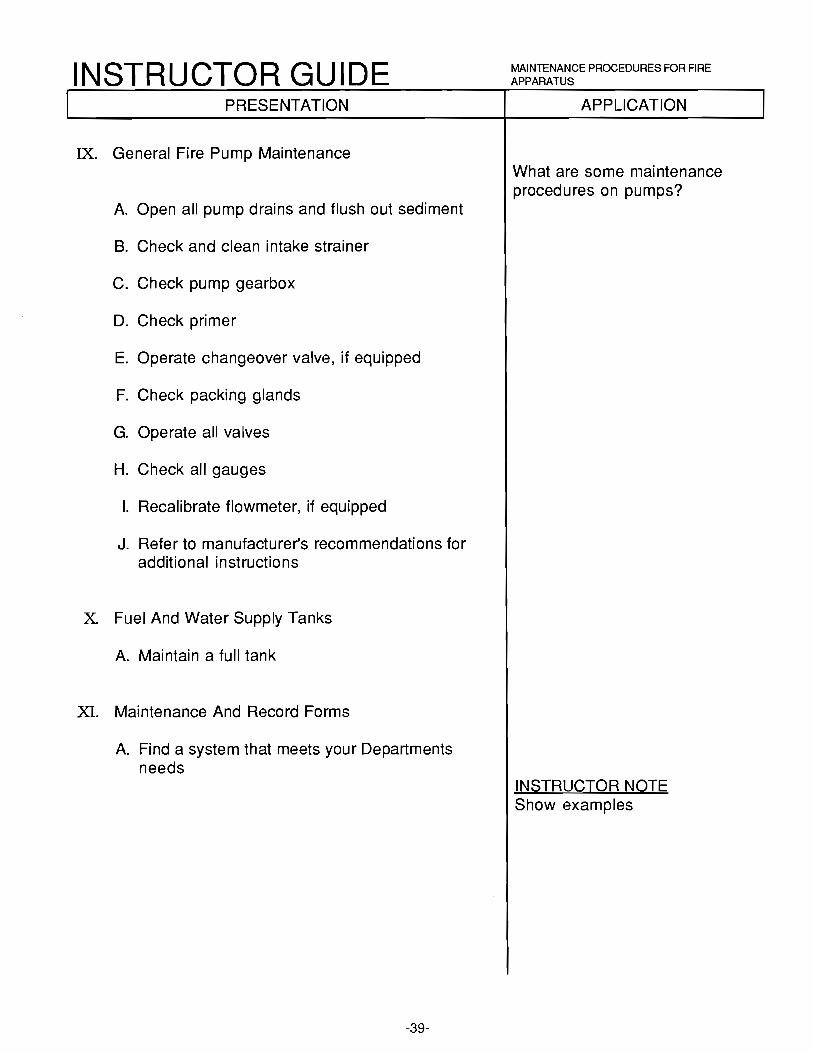
IX. General Fire Pump Maintenance
A. Open all pump drains and flush out sediment
B. Check and clean intake strainer
C. Check pump gearbox
D. Check primer
E. Operate changeover valve, if equipped
F. Check packing glands
G. Operate all valves
H. Check all gauges
I. Recalibrate flowmeter, if equipped
J. Refer to manufacturer's recommendations for additional instructions
X Fuel And Water Supply Tanks
A. Maintain a full tank
XI. Maintenance And Record Forms
A. Find a system that meets your Departments needs
-39-
MAINTENANCE PROCEDURES FOR FIRE APPARATUS
APPLICATION
What are some maintenance procedures on pumps?
INSTRUCTOR NOTE Show examples
INSTRUCTOR GUIDE SUMMARY:
MAINTENANCE PROCEDURES FOR FIRE APPARATUS
Major components of maintenance are cleanliness, records, daily, weekly, and periodic apparatus maintenance. Daily, weekly and periodic equipment maintenance. Electrical components, care of engine, care of chassis, fire pump maintenance, and fuel and water tanks.
EVALUATION:
The student will be evaluated by completing a written examination.
ASSIGNMENT:
Assignment to be determined by the instructor(s).
-40-

INSTRUCTOR GUIDE HOW PRESSURES ACT ON FLUIDS
BASIC PUMP OPERATIONS
Lesson P Ian # 9
TOPIC: How Pressures Act On Fluids
LEVEL: I
TIME: 15 minutes
BEHAVIORAL OBJECTIVE:
Given: A written examination
Performance: The student will demonstrate a working knowledge of how pressure acts on fluids
Standard: With a minimum 70 % accuracy according to the information contained in IFSTA, Fire Streams Practices, 7th Edition, Pages 31 - 33
REFERENCES: IFSTA, Fire Stream Practices, 7th Edition, Pages 31 - 33
MATERIALS NEEDED: Appropriate audio/visual equipment and materials
PREPARATION: The speed with which a fluid travels through a hose is developed by the pressure exerted upon that fluid.
There are six basic principles that determine the action of pressure upon fluids and they should be clearly understood before the kinds of pressures are studied.
-41-

INSTRUCTOR GUIDE PRESENTATION
I. Fluid Pressure Is Perpendicular To Any Surface On Which It Acts
II. Fluid Pressure At Any Point In A Fluid At Rest Is Of The Same Intensity In All Directions
• Fluid pressure at a point, at rest, has no direction
III. Pressure Applied To A Confined Fluid From Without Is Transmitted Equally In All Direction
IV. The Pressure Of A Liquid In An Open Vessel Is Proportional To Its Depth
V. The Pressure Of A Liquid In An open Vessel Is Proportional To The Density Of The Liquid
VI. The Pressure Of A Liquid On The Bottom Of A Vessel Is Independent Of The Shape Of The Vessel
-42-
HOW PRESSURES ACT ON FLUIDS
APPLICATION
INSTRUCTOR NOTE Transparency
INSTRUCTOR NOTE Transparency
INSTRUCTOR NOTE Transparency
INSTRUCTOR NOTE Transparency
INSTRUCTOR NOTE Transparency
11\ISTRUCTOR NOTE Transparency

INSTRUCTOR GUIDE HOW PRESSURES ACT ON FLUIDS
SUMMARY:
By utilizing these principles, you will understand what is happening to both the pump and the hose lines on the fire ground.
EVALUATION:
The student will be evaluated by completing a written examination.
ASSIGNMENT:
To be determined by the instructor(s).
-43-

INSTRUCTOR GUIDE FACTORS AFFECTING FRICllON LOSS
BASIC PUMP OPERATIONS
Lesson Plan # 1 O
TOPIC: Factors Affecting Friction Loss
LEVEL: II
TIME: 30 minutes
BEHAVIORAL OBJECTIVE:
Given: A written examination
Performance: The student will demonstrate a working knowledge of the factors affecting friction loss
Standard: With a minimum 70 % accuracy according to the information contained in IFSTA, Fire Stream Practices, 7th Edition, Pages 37 - 44
REFERENCES: IFSTA, Fire Stream Practices, 7th Edition, Pages 37 - 44
MATERIALS NEEDED: Appropriate audio/visual equipment and materials
PREPARATION: It is important for the pump operator to know and understand friction loss factors to properly pump the correct pressure.
-44-

INSTRUCTOR GUIDE PRESENTATION
I. Friction Loss Is That Part Of Total Pressure That Is Used To Overcome Friction While Forcing Water Through Pipes, Fittings, Fire Hose And Adaptors
• The difference in pressures in a hose line between a nozzle and a pumper is a good example for 'fricton loss
II. Causes Of Friction Loss
A. Movement of water molecules against each other
B. Rough linings in fire hose
• Smooth inner lining causes less friction loss
C. Crushed couplings
D. Sharp bends
• Zig zag patterns of hose add up to 3% more friction loss than hose in a straight line
E. Change in size of orifice by adapters and improper gasket size
F. Old hose may have 50% greater 'friction loss than new
G. Anything that effects movement of water may cause friction loss
III. There Are Four Basic Principals Of Friction Loss
A. All other conditions being the same, the loss by friction varies directly with the length of hose or pipe
B. When the same size of hose is used, the friction loss will vary approximately with the square of the increase in the velocity of the flow
-45-
FACTORS AFFECTING FRICTION LOSS
APPLICATION
What is friction loss?
What are the four basic principles of friction loss?

INSTRUCTOR GUIDE PRESENTATION
C. For the same discharge, friction loss varies inversely as the fifth power of the diameter of the hose
D. For a given velocity of flow, the friction loss in hose is approximately the same, whatever the pressure on the water may be
IV. Critical Velocity Is When The Volocity Of A Stream Becomes So Great That The Entire Stream Is Agitated By Resistance Causing Turbulence
v.
• Increased friction loss
To Reduce Friction Loss
A. Check for rough linings in old hose
B. Replace crushed couplings
C. Eliminate sharp bends
D. Use adaptors only when necessary
E. Keep nozzles and valves fully open when possible
F. Use gaskets of proper size
G. Use short lines as much as possible
H. When flow must be increased, use larger hose or multiple lines
-46-
FACTORS AFFECTING FRICTION LOSS
APPLICATION
What is critical velocity?
How do you reduce friction loss?

INSTRUCTOR GUIDE FACTORS AFFECTING FRICTION LOSS
SUMMARY:
By understanding the principals of friction loss, you will be able to operate your pump at the most effective pressure.
EVALUATION:
The student will be evaluated by completing a written examination.
ASSIGNMENT:
To be determined by the instructor(s).
-47-

INSTRUCTOR GUIDE CALCULATING WATER FLOW IN GALLONS PER MINUTE
BASIC PUMP OPERATIONS
Lesson Plan # 11
TOPIC: Calculating Water Flow In Gallons Per Minute
LEVEL: II
TIME: 15 minutes
BEHAVIORAL OBJECTIVE:
Given: A written examination
Performance: The student will demonstrate a working knowledge of how to calculate water flows in Gallons Per Minute
Standard: With a minimum 70 % accuracy according to the information contained in IFSTA, Fire Stream Practices, 7th Edition, Page 146
REFERENCES: IFSTA, Fire Stream Practices, 7th Edition, Page 146 IFSTA, Fire Stream Practices, 6th Edition, Page 89
MATERIALS NEEDED: Appropriate audio/visual equipment and materials
PREPARATION: To solve many fire ground hydraulics problems you need to determine the gallons per minute flowing. This lesson will provide you with the basic knowledge you need to know to figure the gallons per minute flowing and figure out many ·fire ground hydraulics problems. Some of the methods to calculate hydraulics problems are based on your ability to calculate the gallons per minute flowing.
-48-

INSTRUCTOR GUIDE PRESENTATION
I. Calculation For Gallons Per Minute
A. Gallons Per Minute (Quantity) is the common measurement of water delivered to the fire
• GPM is equal to 29.71 (a given), times the diameter of the orifice squared; times the square root of the nozzle pressure
B. Discharge in Gallons Per Minute from a 1" tip at 100 psi nozzle pressure
1. GPM = 29.71 X D 2
X VP
2. GPM = 29.71 X 1 2
X ..J100
3. GPM = 29.71 X 1 X ..J100
4. GPM=29.71X1 X10
5. GPM = 29.71X10
6. GPM = 297.1
B. Discharge in Gallons Per Minute from a 11 /8" tip at 50 psi nozzle pressure
1. GPM = 29.71 X D 2 X VP
2. GPM = 29.71 X 1 1/8 2
X Vs0 You must now convert fractions to decimals
3. GPM = 29.71 X 1.1252
X Vs0
4. GPM = 29.71 X 1.265 X Vs0
5. GPM = 29.71 X 1.265 X 7.07
6. GPM = 37.58 X 7.07
7. GPM = 265.69
C. Not really
-49-
CALCULATING WATER FLOW IN GALLONS PER MINUTE
APPLICATION
Does tt-iis seem like an easy way to ·figure GPM on the fire ground?

INSTRUCTOR GUIDE PRESENTATION
D. Work the above problem rounding off the given to 30, the orifice size to 2 places past the decimal and the square root to the nearest whole number
1. GPM = 30 X D 2
X .vP"
2. G PM = 30 X 1 1 /8 2
X -v'sQ
3. G PM = 30 X 1 .1 25 2
X -v'sQ
4. G PM = 30 X 1 .1 2 2
X -v'sQ
5. GPM = 30 X 1.25 x-v'SO
6. GPM = 30 X 1.25 X 7
7. GPM = 37.5 X 7
8. GPM = 262.5
II. Gallons Per Minute From Open Butt And Hydrant Openings
• This formula can be expanded to include open butts and hydrant openings by inserting one of several constants to the equation
1. Hose open butts= 0.9
2. Hydrant either 0.7, 0.8, or 0.9 (Based upon the inside contour of the hydrant butt)
-50-
CALCULATING WATER FLOW IN GALLONS PER MINUTE
APPLICATION
INSTRUCTOR NOTE Continue working problems until the students feel comfortable with the equations.

INSTRUCTOR GUIDE PRESENTATION
• What is the discharge in GPM from a 2 1 /2" hose open butt at 25 psi?
1) GPM = 29.71XD2
X ..J25 X 0.9
2) GPM = 30 X 2 1/2 2X ..J25 X 0.9
3) GPM = 30 X 2.5 2X..J25 X 0.9
4) GPM = 30 X 6.25 X ..J25 X 0.9
5) GPM = 30 X 6.25 X 5 X 0.9
6) GPM = 187.5 X 5 X 0.9
7) GPM = 397.5 X 0.9
8) GPM = 843.75
-51-
CALCULATING WATER FLOW IN GALLONS PER MINUTE
APPLICATION
INSTRUCTOR GUIDE
SUMMARY:
CALCULATING WATER FLOW IN GALLONS PER MINUTE
Armed with the knowledge and ability to solve for the gallons per minute flowing, you should be able to go on to solve many fire ground hydraulics problems.
EVALUATION:
The student will be evaluated by completing a written examination.
ASSIGNMENT:
To be determined by the instructor(s).
-52-

INSTRUCTOR GUIDE CALCULATE ENGINE PRESSURE
BASIC PUMP OPERATIONS
Lesson Plan# 12
TOPIC: Calculate Engine Pressure
LEVEL: I I
15 minutes
BEHAVIORAL OBJECTIVE:
Given: A written examination
Performance: The student will demonstrate a working knowledge of the solutions to hydraulic problems when using written formulas
Standard: With a minimum 70 % accuracy according to the information contained in IFSTA, Fire Streams Practices, 7th Edition, Pages 191 - 192
REFERENCES: IFSTA, Fire Streams Practices, 7th Edition, Pages 191 - 192 Techniques of Fire Hydraulics, 1st Edition, Glencoe Press, Chapters 8-1 1
MATERIALS NEEDED: Appropriate audio/visual equipment and materials
PREPARATION: Perhaps firefighters fear their mathematical skills are so bad that they would not be able to function in the classroom. Maybe they think they will be required to make exact calculations on the fire ground or that it is a waste of time.
The way we intend to teach this course is to ·first address the theoretical half of hydraulics with its formulas and concepts. The theory that is learned will greatly help you apply your fire ground (practical) formulas to every situation you encounter and know why you are doing it.
-53-

INSTRUCTOR GUIDE PRESENTATION
I. Engine Pressure Equals The Nozzle Pressure, Plus Friction Loss, Plus Or Minus Head Elevation, Plus Pressure Loss Due To Appliances
• EP (PDP)= NP :1:. FL+ H +A
1. EP = Engine Pressure or
PDP= Pump Discharge Pressure
2. NP = Nozzle Pressure
3. FL= Friction Loss in hose
4. H =Head
5. A = Appliance friction loss
II. Nozzle Pressure Is The Water Pressure Desired At The Nozzle
A. Hand line solid stream
• 50 psi
B. All fog nozzles
• 100 psi
C. Master streams
1. 80 psi - Solid stream
2. 100 psi - Fog nozzle
III. Friction Loss Is The Loss Of Water Pressure In Hose, Pipe And Fittings
-54-
CALCULATE ENGINE PRESSURE
APPLICATION
INSTRUCTOR GUIDE PRESENTATION
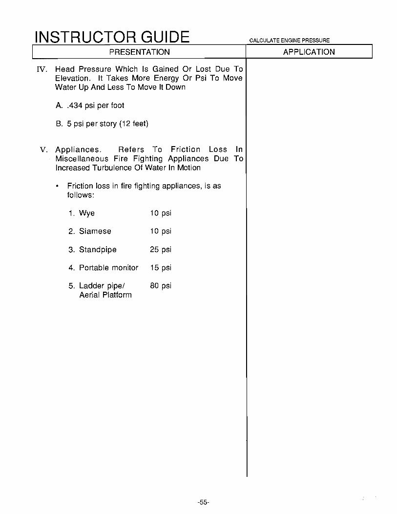
IV. Head Pressure Which Is Gained Or Lost Due To Elevation. It Takes More Energy Or Psi To Move Water Up And Less To Move It Down
A. .434 psi per foot
B. 5 psi per story (12 feet)
v. Appliances. Refers To Friction Loss In Miscellaneous Fire Fighting Appliances Due To Increased Turbulence Of Water In Motion
• Friction loss in fire fighting appliances, is as follows:
1. Wye 1 o psi
2. Siamese 1 o psi
3. Standpipe 25 psi
4. Portable monitor 15 psi
5. Ladder pipe/ 80 psi Aerial Platform
-55-
CALCULATE ENGINE PRESSURE
APPLICATION

INSTRUCTOR GUIDE CALCULATE ENGINE PRESSURE
SUMMARY:
It is very important to the pump operator to be able to solve hydraulics problems. The understanding of this simple formula is of great importance to you as you perform your duties. You should now be able to solve hydraulic problems when using written formulas which include EP, PDP, NP, FL, Hand A.
EVALUATION:
The student will be evaluated by completing a written examination.
ASSIGNMENT:
Read IFSTA, Fire Streams Practices, 7th Edition, Pages 191 - 197.
-56-

INSTRUCTOR GUIDE PRINCIPLES OF FIRE FIGHTING HYDRAULICS
BASIC PUMP OPERATIONS
Lesson Plan # 13
TOPIC: Principles Of Fire Fighting Hydraulics
LEVEL: II
TIME: 30 minutes
BEHAVIORAL OBJECTIVE:
Given:
Performance:
Standard:
REFERENCES:
A written examination
The student will demonstrate a working knowledge of the definitions and terms used in basic hydraulics, describe fluid hydraulics, factors affecting friction loss and maximum lift
With a minimum 70 % accuracy according to the information contained in IFSTA Fire Streams Practices, 7th Edition, Pages 36 - 43 and 202 -204
IFSTA, Fire Streams Practices, 7th Edition, Pages 36 - 43 and 202 -204 Fire Fighting Apparatus and Procedures, Erven, 3rd Edition, 1979 Fire Service Pump Operator's Handbook, lsman, 1st Edition, 1984, Fire Engineering
MATERIALS NEEDED: Appropriate audio/visual equipment and materials
PREPARATION: Every fire fighter, whether the highest ranking chief officer or a new recruit, should possess a good practical working knowledge of hydraulics so that fire 'fighting tactics will have a sound basis and fire streams will be both safe and effective.
Although many industries have installed fire fighting appliances that can be put into service at a moments notice, most fires are ultimately controlled and extinguished by fire fighters with hose lines.
-57-

INSTRUCTOR GUIDE PRESENTATION
I. Friction Loss
A. Commonly, loss of pressure in fire hose, pipe, and fittings
• The actual friction loss is resistance to motion between the water and inside of the hose or fitting, as well as to friction between the water particles themselves
B. Friction losses in a fire stream are due to the ·friction of the water stream upon different parts of the waterway, such as upon the interior surfaces of the hose, the couplings, the valves, the gaskets, the hose appliance, etc. It is an everpresent hindering force and must be overcome
C. Good quality fire hose has a smoother inter surface, that will create less friction than hose of a lower grade
D. Friction loss in old hose may be 50% greater than in new hose
II. Fundamental Rules Governing Friction Loss
A. All other conditions being equal, the loss by friction varies directly with the lenght of line
• If friction loss for a given flow is 1 O psi/100 feet of 2 1/2" hose, then as long as the conditions remain the same, there will be an additional 1 O psi loss in each additional 100 feet of 2 1/2" hose
B. In the same size hose, friction loss varies directly as the square of the velocity flow
• As the flow increases, the friction loss also increases, but at a much greater rate
• Flow doubled, friction loss will be 2 X 2, or 4 ti mes as great
-58-
PRINCIPLES OF FIRE FIGHTING HYDRAULICS
APPLICATION
What is Friction Loss?

INSTRUCTOR GUIDE
III.
PRESENTATION
C. For a given velocity of now, friction loss is independent of the pressure
• This means that the larger the hose diameter, the less the friction loss, or the smaller the hose, the greater the friction loss
(diameter of larger hose) 5
=----------(diameter of smaller hose)5
D. For a given velocity of flow, friction loss is independent of the pressure
• As long as velocity of flow does not change, friction loss will remain the same regardless of pressure changes. The velocity of the flow, not pressure, is the determining factor in friction loss
Factors Affecting Friction Loss
A. Check for rough linings in old hose
B. Replace crushed couplings
C. Eliminate sharp bends
D. Use adapters only when necessary
E. Keep nozzles and valves fully open, when possible
F. Use gaskets of the proper size
G. Use short lines as much as possible
H. When flow must be increased, use larger hose or multiple lines
-59-
PRINCIPLES OF FIRE FIGHTING HYDRAULICS
APPLICATION

INSTRUCTOR GUIDE PRESENTATION
IV. Lift
A. Since 1 lb. of pressure will raise a column of water to a height of 2.304 feet, 14.7 lbs. will raise a column of water to a height of (14.7 X 2.304) 33.8688 or 33.9 feet
B. Maximum theoretical height for it to be possible to lift water by suction at sea level
• Impossible to create a perfect vacuum even with the most delicate of scientific apparatus
C. Common practice is to use two-thirds of the theoretical distance, or 22.6 feet at sea level, for the practical limit of draft, or lift
D. Atmospheric pressure decreases as elevation above sea level increases, at a rate of approximately 1 /2 lb. for every 1000 feet of elevation
E. For practical purposes, 1 in. of mercury (Hg) equals 1/2 psi of pressure; water will rise approximately 1 foot in the suction hose for each inch of vacuum within the suction hose
V. Static, Flow And Residual Pressures
A. Static Pressure is the pressure of the water when motionless
• Water in a fire hydrant is under static pressure as long as the valve is not opened
B. Flow Pressure cannot be as great as static pressure because after the fire stream is set in motion, it is subjected to all the hindrances the waterway possesses, such as friction, short bends, etc.
C. Residual Pressure is the pressure rema1n1ng when the valve is open and the water is flowing
-60-
PRINCIPLES OF FIRE FIGHTING HYDRAULICS
APPLICATION

INSTRUCTOR GUIDE PRESENTATION
VI. Head Pressure
A. Normal atmospheric pressure at sea level may be considered to be 14.7 lb. psi
B. For practical purposes it may be assumed that water is incompressible
C. It may be said that a given weight of water will always occupy the same space, and a given volume will always have the same weight
D. A column of water 1 foot high with a cross-section of 1 square inch will weigh .434 lb. (.434 psi), and 1 lb. of water will fill the same column to a height of 2.304 feet (1 psi will raise a column of water 2.304 feet)
• Pressure exerted by a column of water is known as Head Pressure
VII. Pressure Loss Or Gain Because Of Elevation
A. One pound per square inch pressure is required to raise water in a fire hose or pipe 2.304 feet
• Five psi is required to raise water one story
• A story is 12 feet high
B. Vertical drop requires the same consideration
C. For fire ground operations, 5 psi for every 1 O feet of change
-61-
PRINCIPLES OF FIRE FIGHTING HYDRAULICS
APPLICATION

INSTRUCTOR GUIDE PRINCIPLES OF FIRE FIGHTING HYDRAULICS
SUMMARY:
One must know the principles of hydraulics to calculate hydraulics, just like one must learn how to walk before they can run.
Now that you can walk, let's learn how to run.
EVALUATION:
The student will be evaluated by completing a written examination.
ASSIGNMENT:
Complete the Fire Ground Hydraulics Worksheet.
-62-

INSTRUCTOR GUIDE CALCULATE FRICTION LOSS IN SINGLE AND MULTIPLE LINES
BASIC PUMP OPERATIONS
Lesson Plan # 14
TOPIC: Calculate Friction Loss In Single And Multiple Lines
LEVEL: II
1 hour
BEHAVIORAL OBJECTIVE:
Given: A written/oral examination
Performance: The student will demonstrate a workinh knowledge of how to calculate friction loss in single and multiple lines
Standard: With a minimum 70 % accuracy according to the information contained in IFSTA, Fire Stream Practices, 7th Edition, Pages 148 - 187
REFERENCES: IFSTA, Fire Stream Practices, 7th Edition, Pages 148 - 187
MATERIALS NEEDED: Appropriate audio/visual equipment and materials
PREPARATION: Apparatus operators must be able to calculate friction loss in a hose lay to obtain the proper nozzle pressure. Failure to account for friction loss will result in decreased water flow at the nozzle. If you incorrectly 'figure the friction loss, you may over or under pressure the hose line which could injure the nozzle person.
-63-

INSTRUCTOR GUIDE PRESENTATION
I. Need To Determine Gallons Per Minute Flowing
A. Know rated GPM of nozzles
B. Use GPM formula
II. Q Formula
A. Example: O=GPM 100
• Q = 200 (Gallons Per Minute) 100
B. Short Cut
• Move decimal point to the left two places
a) GPM = 200
b) GPM =2.00
C. After a value for Q has been found, use this formula to find F.L. per 100 feet of 2 1/2" hose
III. Theoretical Formula (FL= 2 Q 2 + Q)
A. Calculate a 2 1/2" line flowing 200 GPM
• FL=20 2 +Q FL= 2 (2) 2 + 2 FL= 2 (4) + 2 FL= 8 + 2 FL= 1 O psi per 100 feet
-64-
CALCULATE FRICTION LOSS IN SINGLE AND MULTIPLE LINES
APPLICATION
What is the Q Formula?
What is the F.L. Formula?
INSTRUCTOR NOTE Calculate Problem

INSTRUCTOR GUIDE PRESENTATION
B. With flows near to or less than 100 GPM
IV. Simplified Formula
A. C 0 2 L
1. C = Coefficient for hose size
2. O=GPM 100
3. L = Number of 100 foot lenghts of hose in lay
B. The following coefficients are to calculate friction loss per 100' in hose
Hose Size C Factor
3/4" 1100 1" 150 1 1/2" 24 1 3/4" 15.5 2 1/2" 2 3" .80 3 1/2" .34 4" .2 5" .08
C. Calculate 250 GPM flowing through a single 2 1 /2" line 100' long
2 1. FL= C Q L FL= 2 (2.5) 2 1 FL = 2 (6.25) 1 FL= 12.5 FL = 12.5 per 1 00' length of hose
-65-
CALCULATE FRICTION LOSS IN SINGLE AND MULTIPLE LINES
APPLICATION
INSTRUCTOR NOTE Calculate Problem

INSTRUCTOR GUIDE PRESENTATION
D. Calculate 300 GPM flowing through a single 2 1 /2" line 100' long
• FL= C 0 L FL= 2 (3) 2 1 FL= 2 (9) 1 FL= 18 FL= 18 per 100' length of hose
V. Multiple Hose Lines Are Several Hose Lines Orginating At The Pump
A. Figure friction loss in each line
1. First line: 1-2 1 /2" line 250' long with a 1" tip
2. Second line: 1-1 1 /2" hose line 200' long with a 100 GPM fog nozzle
Line 1
FL= C 02
L
FL = 2 (2) 2 2.5 FL= 2 (4) 2.5 FL= 8 x 2.5 FL= 20 psi
Line 2
FL= C 0 2 L
FL= 24 (1) 2 2 FL= 24 (1) 2 FL= 24 x 2 FL= 48 psi
-66-
CALCULATE FRICTION LOSS IN SINGLE AND MULTIPLE LINES
APPLICATION
INSTRUCTOR NOTE Calculate Problem
What are multiple hose lines?
How do you figure FL in multiple lines?

INSTRUCTOR GUIDE PRESENTATION
B. Remember to total 'friction loss for each hose line and set the pump for the one which will require the highest Engine Pressure
C. Gate down discharges of the lines needing less pressure
-67-
CALCULATE FRICTION LOSS IN SINGLE AND MULTIPLE LINES
APPLICATION

INSTRUCTOR GUIDE
SUMMARY:
CALCULATE FRICTION LOSS IN SINGLE AND MULTIPLE LINES
These friction loss calculations will help you in determining the engine pressures required to provide the proper nozzle pressure on the fire ground.
EV ALU A Tl ON:
The student will be evaluated by completing a written examination and oral questions.
ASSIGNMENT:
Assignment to be determined by the instructor(s).
-68-

INSTRUCTOR GUIDE CALCULATING FRICTION LOSS FOR WYED LINES, SIAMESED LINES AND MASTER STREAMS
TOPIC:
LEVEL:
BASIC PUMP OPERATIONS
Lesson Plan# 15
Calculating Friction Loss For Wyed Lines, Siamesed Lines and Master Streams
II
1 hour
BEHAVIORAL OB . .JECTIVE:
Given: A written/oral examination
Performance: The student will demonstrate a working knowledge of how to calculate friction loss for wyed lines, siamesed lines and master streams
Standard: With a minimum 70 % accuracy according to the information contained in IFSTA, Fire Stream Practices, 7th Edition, Pages 148 - 187
REFERENCES: IFSTA, Fire Stream Practices, 7th Edition, Pages 148 - 187
MATERIALS NEEDED: Appropriate audio/visual equipment and materials
PREPARATION: As our fire problems increase in size, so does the need to deliver larger quantities of water to control; and extinguish these fires. This calls for wyed lines to deliver water at multiple locations, and siamesed lines to deliver large quantities of water over long distances or to supply master streams. When using these types of hose lays, additional information for 'figuring out your 'friction loss must be considered.
-69-

INSTRUCTOR GUIDE PRESENTATION
I. A Wyed Hose Lay Is One Hose Line Which Supplies Two Hose Lines
A. The "wye" appliance takes one hose line in, and splits to two hose lines out
B. Two 1 1/2" fog lines wyed from a 2 1/2" supply hose is common
1. Other combinations are readily adaptable
2. Supply line will be of the same size or larger
II. GPM Formula For Each Line, Then Added Together
A. Example: 200' of 2 1 /2" hose supplying 2 wyed 1 1 /2" fog lines 200' in length, flowing 100 GPM each
• Total GPM = 200
B. Figure the friction loss for the flow through one 1 1 /2" fog line (100 GPM)
• FL= C 0 2 L
FL= 24 (1) 2 2 FL= 24 x 2 FL= 48
-70-
CALCULATING FRICTION LOSS FOR WYED LINES, SIAMESED LINES AND MASTER STREAMS
APPLICATION
What is a wyed hose lay?
How do you determine your GPM?
How do you figure the engine pressure?

INSTRUCTOR GUIDE PRESENTATION
C. Figure the friction loss for the flow through the 2 1/2" line
• FL= C 0 2L
FL= 2 (2)2 2 FL= 2 (4) 2 FL= 8 x 2 FL= 16
D. Figure the friction loss for the wye appliance
• FL= 10 psi
E. Figure the engine pressure
• EP = NP + FL ± H + A
a) EP = 100 + (48 + 16) + 10
b) E P = 1 7 4 psi
F. Give examples using different sizes and lengths of hose
III. Fire Streams Using Cotton Hose Require Large Volumes Of Water, Or When Hose Lays Are Long, You May Lay Two Or More Lines Parallel To Each Other And Siamese Them Together At Some Point Close To The Fire
A. Two hose lines of equal length will have 25% of the friction loss of a single line with equal flow
B. Three hose lines of equal length will have 10% of the friction loss of a single line with equal flow
-71-
CALCULATING FRICTION LOSS FOR WYED LINES, SIAMESED LINES AND MASTER STREAMS
APPLICATION
INSTRUCTOR NOTE NP= Nozzle Pressure FL= Friction Loss H =Head A = Appliance
What are siamesed hose lines?

INSTRUCTOR GUIDE PRESENTATION
IV. Determine The GPM Flow Required
A. By size and number of the hose
B. Nozzle tip size and design
C. Supply requirements
D. GPM formula
V. To Figure The Engine Pressure, For Two Siamesed Lines Of Equal Size And Length, Take 1/2 Of The GPM Flow And Figure The Friction Loss For One Line
A. Example: 400 feet of 2 1/2" line siamesed to a single 200' of 2 1/2" line flowing 200 GPM
2 1. FL= C Q L
a) Siamesed Section:
FL=2 (1)2 4 FL= 8
b) Single Section:
2 FL= 2 (2) 2 FL= 16
c) Siamese appliance= 10 psi
2. EP =HP+ FL± H +A
• EP = 50 + (8 + 16) + 10 EP = 84 psi
B. Give examples using different sizes and lengths of hose
-72-
CALCULATING FRICTION LOSS FOR WYED LINES, SIAMESED LINES AND MASTER STREAMS
APPLICATION
How to you determine your GPM?
How do you figure the engine pressure?

INSTRUCTOR GUIDE PRESENTATION
C. To figure friction loss of siamesed hose lines of different length, add the length of each line together, then divide by the number of lines
• Example: 400' and 500' of 2 1/2" line siamesed together.
a) 400' + 500' = 900' divided by 2 = 450'
b) Figure single length at 450'
D. To figure the engine pressure of a siamesed hose line of 2 1 /2" and 3" hose, 'figure the friction loss per 1 00' (CO 2 ) and multiply this by 1 /6. Take this figure and calculate the hose lay as a single 2 1/2"
1. Example: 200' of siamesed 2 1 /2" and 3" line supplying a master stream flowing 800 GPM
a) C02
= Friction Loss/100' 2 (8) 2 = FU100' 1 28 = FL/1 00'
b) 1 /6 x 128 = 21 .3
c) 21.3 x 2 (length of lines= 42.6)
d) EP =HP+ FL± H +A
EP = 80 + 42.6 + 15 EP = 137.6 psi
2. Give other examples
-73-
CALCULATING FRICTION LOSS FOR WYED LINES, SIAMESED LINES AND MASTER STREAMS
APPLICATION
How do you determine friction loss of siamese lines of unequal length?
How do you figure siamese hose lines of unequal size? ( 2 1 /2" and 3")

INSTRUCTOR GUIDE PRESENTATION
E. To figure siamesed hose lays of 3 or more lines of equal size, divide the GPM by the number of lines. This figure you the GPM per line. Then calculate the friction loss for one line
• Example: Three lines 400' long siamesed to a master stream flowing 600 GPM
a) 600 divided by 3 = 200 GPM per line
b) FL= 2 (2) 2
4 FL= 32
c) EP =HP+ FL± H +A
E P = 80 + 32 + 15 EP = 127 psi
VI. You Supply Master Streams With Large Diameter Hose (LDH) Of Siamesed Hose Lines Due To The Large Volumes Of Water
-74-
CALCULATING FRICTION LOSS FOR WYED LINES, SIAMESED LINES AND MASTER STREAMS
APPLICATION
How do you figure three or more lines?
How do you supply master streams?
How do you figure the engine pressure?

INSTRUCTOR GUIDE PRESENTATION
VII. Since The GPM Is The Factor Determining Friction Loss, The Capacity Of Each Master Stream Nozzle Is The Key
A. Approximate flows for master streams at 80 psi
NOZZLE TIP SIZE
1 1/4" 1 3/8" 1 1/2" 1 5/8" 1 3/4" 2"
ACTUAL LOW
413 500 596 700 813 1063
APPROXIMATE FLOW
400 500 600 700 800 1000
B. Select the nozzle tip appropriate for your GPM requirements
C. For Large Diameter Hose, ·figure the friction loss
2. EP =HP+ FL± H +A
3. Give examples
D. For siamesed lines, divide the GPM by the number of lines. T~lis gives you the GPM per line. Then figure the friction loss for one line
• Example: Four lines supplying 800 GPM
• 800 divided by 4 = 200 GPM per line
-75-
CALCULATING FRICTION LOSS FOR WYED LINES, SIAMESED LINES AND MASTER STREAMS
APPLICATION
What ar the flows of the various master stream nozzles?

INSTRUCTOR GUIDE SUMMARY:
CALCULATING FRICTION LOSS FOR WYED LINES, SIAMESED LINES AND MASTER STREAMS
To efficiently pump wyed and siamesed lines, reduce the total GPM flow to the actual flow of each line, then figure the friction loss of one hose. Remember to add in the friction loss of the appliance.
EVALUATION:
The student will be evaluated by completing a written! examination and oral questions.
ASSIGNMENT:
Assignment to be determined by the instructor(s).
-76-
INSTRUCTOR GUIDE HOW TO TAKE WATER FROM THE TANK
BASIC PUMP OPERATIONS
Lesson Plan # 16
TOPIC: How To Take Water From The Tank
LEVEL: I
TIME: 30 minutes
BEHAVIORAL OBJECTIVE:
Given: One engine company with standard equipment
Performance: The student will demonstrate how to operate from the tank supply on the apparatus
Standard: Completing all operations within 1 minute according to the job breakdown with 70% accuracy and no safety errors
REFERENCES: Fire Fighting Apparatus and Procedures, Glencoe Press, 3rd Edition, Chapter 6
MATERIALS NEEDED: Equipment needed for the manipulative job and stopwatch. One job breakdown per student. One job breakdown for evaluation per student. Any/total equipment needed for all groups to perform the job.
PREPARATION: The majority of fires we respond to are handled by the water tank (booster tank) found on the apparatus. Therfore, it is the operators responsibility to be able to supply water from the apparatus tank.
-77-

INSTRUCTOR GUIDE HOW TO TAKE WATER FROM THE TANK
OPERATIONS PRESENTATION KEY POINTS
1. Position pumper
2. Set parking brake
3. Place pump in gear
4. Exit pumper
5. Place chock block(s)
6. Check valve controls
7. Open tank to pump valve, if not already open
8. Pump water
9. Open discharge(s)
10. Set relief valve
11. Monitor water level
1 a. Correct location
3a. Use proper gear, according to manufacture guidelines
b. Pump drive engaged
4a. Watch traffic
5a. Any other department safety devices
6a. Pump drains closed
b. Relief valve closed or set
Ba. Short engagement of primer, if necessary
b. Hose lines attached
9a. Advance throttle to desired pressure
1 Oa. According to department policy
11 a. Limited amount
b. With no water flowing, consider some type of by-pass
-78-

INSTRUCTOR GUIDE HOW TO TAKE WATER FROM THE TANK
APPLICATION:
Pumping from the tank follows a sequence where any one step missed could mean not getting water at the nozzle. Refresh each step in sequence and practice, so no area is overlooked.
EVALUATION:
Have each student individually perform the skill desired.
ASSIGNMENT:
Study student handouts/job breakdown.
Continue to practice this skill as you will be tested during a final review session.
-79-

INSTRUCTOR GUIDE HOW TO OPERA TE FROM A HYDRANT
BASIC PUMP OPERATIONS
Lesson Plan# 17
TOPIC: How To Operate From A Hydrant
LEVEL: I
1 hour
BEHAVIORAL OBJECTIVE:
Given:
Performance:
Standard:
REFERENCES:
A Fire Department Engine
The student will demonstrate how to operate the engine at a hydrant
Completing all operations within three minutes (3) according to the job breakdown with no safety errors, to 70 % accuracy
IFSTA, Pumping Apparatus, 7th Edition, Pages 251 - 357 Fire Fighting Apparatus and Procedures, 3rd Edition, Glencoe Press, Pages 252 - 264
MATERIALS NEEDED: Fire Department pumper, soft suction hoses, assorted hydrant wrenches, spanner wrenches and a hydrant
PREPARATION: As fire conditions warrant, pumping from a hydrant enables the operator a continuous flow of water under pressure. Because of the severity of fire, when hooking up is done, smooth and quick action must take place so fire fighting operations can begin.
-80-

INSTRUCTOR GUIDE HOW TO OPERA TE FROM A HYDRANT
OPERATIONS PRESENTATION
KEY POINTS
1. Spot the engine at the hydrant
2. Set parking brake
3. Place pum in gear
4. Exit engine
5. Place chock block(s)
6. Crack open hydrant/close hydrant
7. Attach hose to hydrant
8. Open hydrant fully
9. Open inlet (intake)
10. Attach required hoses
11. Open discharges
12. Adjust throttle
13. Set relief valve
14. Check gauges
1 a. Proper distance
3a. Use proper gear, according to manufacture guidelines
b. Pump drive engaged
4a. Watch traffic
5a. Any other department safety devices
6a. To clear debris from hydrant
?a. Proper size intake suction 2 1 /2" vs. 4 1 /2"
b. No kinks in suction
9a. Slowly
b. Note static pressure
13a. According to department policy
14a. Check residual pressure
b. Estimate water available
c. Monitor pressures and temperature
-81-

INSTRUCTOR GUIDE HOW TO OPERA TE FROM A HYDRANT
APPLICATION:
Operations hydrants have to be followed in step by step sequences. Practice is necessary to insure no step is overlooked.
EVALUATION:
The student will demonstrate how to operate the engine at a hydrant. Completing all operations within three (3) minutes according to the job breakdown with no safety errors, to 70 % accuracy.
ASSIGNMENT:
To be determined by the instructor(s).
-82-
INSTRUCTOR GUIDE PURPOSE AND OPERATION OF PRIMING SYSTEMS
BASIC PUMP OPERATIONS
Lesson Plan# 18
TOPIC: Purpose And Operation Of Priming Systems
LEVEL: I
30 minutes
BEHAVIORAL OBJECTIVE:
Given:
Performance:
Standard:
REFERENCES:
A written examination
The student will demonstrate a working knowledge the purpose and operation of the various types of priming systems used in the fire service
With a minimum 70 % accuracy according to the information contained in IFSTA, Pumping Apparatus, 7th Edition, Pages 86 - 90 and Pages 251 - 357
NFPA 1901 IFSTA, Pumping Apparatus, 7th Edition, Pages 86 - 90 and Pages 251 - 357 Fire Service Pump Operators Handbook, lsman, Fire Engineering, 1984, Pages 169 -181
MATERIALS NEEDED: Appropriate audio/visual equipment and materials
PREPARATION: Priming systems are necessary to operate centrifugal fire pumps in some applications. The proper operation of priming systems are paramount to successfully combating fire. Drafting operations with centrifugal pumps require the operator to know the purpose and operation of priming systems.
-83-

INSTRUCTOR GUIDE PRESENTATION
I. Priming Devices Are An Essential Part Of Centrifugal Fire Pumps
A. Centrifugal pumps cannot pump air
B. Provides water to the impeller
II. Priming Devices Operate As The Result Or Air Pressure Differential
A. Relies on atmospheric pressure
B. Reduce air pressure within the pump cavity
III. NFPA Priming Device Performance
A. Must be able to develop 22" hg (mercury)
B. When used at draft
1. Pump intake centered 10 feet above the water surface
2. Twenty feet of proper size non-collapsible intake hose
3. Within 30 seconds (45 seconds for 1500 gpm or larger ·fire pumps)
4. Allow 1 O" drop in 10 minutes maximum standard
• When preforming a dry vacuum test
-84-
PURPOSE AND OPERATION OF PRIMING SYSTEMS
APPLICATION
Why are priming devices needed?
What principles are employed in priming device operation?
Do priming devices have performance guidelines?
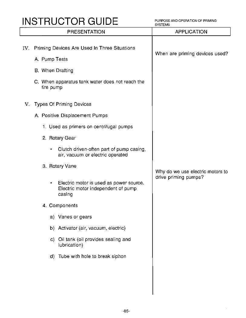
INSTRUCTOR GUIDE PRESENTATION
IV. Priming Devices Are Used In Three Situations
A. Pump Tests
8. When Drafting
C. When apparatus tank water does not reach the fire pump
V. Types Of Priming Devices
A. Positive Displacement Pumps
1. Used as primers on centrifugal pumps
2. Rotary Gear
• Clutch driven-often part of pump casing, air, vacuum or electric operated
3. Rotary Vane
• Electric motor is used as power source. Electric motor independent of pump casing
4. Components
a) Vanes or gears
b) Activator (air, vacuum, electric)
c) Oil tank (oil provides sealing and lubrication)
d) Tube with hole to break siphon
-85-
PURPOSE AND OPERATION OF PRIMING SYSTEMS
APPLICATION
When are priming devices used?
Why do we use electric motors to drive priming pumps?

INSTRUCTOR GUIDE PRESENTATION
B. Vacuum Primers
1. Diesel engines produce no vacuum
2. Gasoline engines create vacuum at the intake manifold
3. Connected between pump and intake maniford to utilize vacuum when necessary
4. Considerations when using a vacuum primer
a) Water must be prevented from being drawn into the engine
b) Gases from a backfire must be prevented from being forced into the pump
C. Engine Exhaust Priming System
1. An integral part of the exhaust system
• A separate chamber, used when needed by the operator
2. Operation
• Application of Bernoullis' Laws
1) Venturi Principle
• Simpliy stated, " A liquid/gas passing through a restriction increases in velocity and decreases in pressure."
2) Relatively high engine RPM's are needed
-86-
PURPOSE AND OPERATION OF PRIMING SYSTEMS
APPLICATION
Why are vacuum primers not used on diesel engines?
How does this apply?

INSTRUCTOR GUIDE SUMMARY:
PURPOSE AND OPERATION OF PRIMING SYSTEMS
There are three types of priming systems: positive displacement, vacuum and exhaust. Priming systems are necessary when using a centrifugal pumps. The Operator must know and understand the purpose and operation of priming systems to be successful on the fire ground.
EVALUATION:
The student will be evaluated by completing a written examination.
ASSIGNMENT:
To be determined by the instructor(s).
-87-

INSTRUCTOR GUIDE PRINCIPLES INVOLVED IN DRAFrlNG
BASIC PUMP OPERATIONS
Lesson Plan# 19
TOPIC: Principles Involved In Drafting Water
LEVEL: I
30 minutes
BEHAVIORAL OBJECTIVE:
Given: A written examination
Performance: The student will demonstrate a working knowledge of the principles involved in drafting water
Standard: With a minimum 70 % accuracy according to the information contained in IFSTA, Pumping Apparatus, 7th Edition, Pages 141 - 144
REFERENCES: IFSTA, Pumping Apparatus, 7th Edition, Pages 141 - 144 Fire Fighting Apparatus and Procedures, 3th Edition, Glocoe, Pages 318 - 319
MATERIALS NEEDED: Appropriate audio/visual equipment and materials
PREPARATION: Drafting water is another means by which water can be introduced into a pump. If a pump operator is not familiar with how water can be drafted, thier ability to maximize the effectiveness of thier pumping apparatus is diminished.
-88-

INSTRUCTOR GUIDE PRESENTATION
I. Basic Principles Of Lift
A. Utilizing atmospheric pressure
B. Definition:
• It is the difference in elevation between the surface of the water and the center of the pump intake
C. Theory
1. Water cannot be pulled or sucked into a pump
2. Force is required to push water upward
3. Atmospheric pressure, w~1ic~1 is 14.7 psi at sea level
D. Limitations
1. Reduction of 1 psi 1n pump will allow atmospheric pressure to push water up intake hose 2.3 feet
2. The maximum theoretical height to which water can be lifted is 33.9 feet
a) 14.7 psi X 2.3 feet = 33.9 feet in a perfect vacuum
b) No perfect vacuum can be created
3. Dependable maximum lift for most fire department engines will be 15 to 20 feet
4. The lesser the atmospheric pressure, the less the maximum lift
• You lose .5 or 1 /2 pound of atmospheric pressure for every 1000 feet of elevation
-89-
PRINCIPLES INVOLVED IN DRAFTING
APPLICATION
How is water lifted into a pump?
What is meant by "lift"?
Where does this force come from?

INSTRUCTOR GUIDE PRINCIPLES INVOLVED IN DRAFrlNG
SUMMARY:
Water is pushed into a pump by atmospheric pressure and not sucked up by the pump and suction hose. Lift is the difference in elevation between the surface of the water and the center of the pump intake. Dependable maximum lift for most fire department engines will be 15 to 20 feet.
EVALUATION:
The student will be evaluated by completing a written examination.
ASSIGNMENT:
To be determined by the instructor(s).
-90-

INSTRUCTOR GUIDE TAKING WATER BY DRAFTING
BASIC PUMP OPERATIONS
Lesson Plan # 20
TOPIC: Taking Water By Drafting
LEVEL: II
TIME: 1 hour
BEHAVIORAL OBJECTIVE:
Given:
Performance:
Standard:
REFERENCES:
A written examination
The student will demonstrate a working knowledge of the steps needed to operate an engine at draft
With a minimum 70 % accuracy according to the information contained in IFSTA, Pumping Apparatus, 7th Edition, Pages 141 - 147
IFSTA, Pumping Apparatus, 7th Edition, Pages 141 - 147 Fire Service Pump Operators Handbook, lsman, 1984, Fire Engineering, Pages 182 - 188 NFPA 1901 Fire Fighting Apparatus and Procedures, Erven, 3rd Edition
MATERIALS NEEDED: Appropriate audio/visual equipment and materials
PREPARATION: During some operations it will be necessary for the operator to provide water while at draft. The knowledge of how to perform this task, is important in fighting fires.
-91-

INSTRUCTOR GUIDE PRESENTATION
I. Spot Apparatus Safely
• Consider
1. Terrain
2. Possibility of long duration pumping
II. Connect Proper Sized Hard Suction Hose
• Secure a safety line to the suction strainer
III. Close All Connections And Shut All Valves
• It must be done in a systematic order
• It is important to develop a system to minimize errors
a) Top mounted panels
b) Front mounted panels
c) Rear mounted panels
d) Lift side panels
IV. On Multi-Stage Pumps, Place Transfer Vlaves In Volume Position
V. Return To Cab
VI. Engage Pump
VII. Return To Pump Panel
-92-
TAKING WATER BY DRAFTING
APPLICATION
Why does the operator need a systematic approach?

INSTRUCTOR GUIDE PRESENTATION
VIII. Increase Engine RPM's
A. Follow manufacturer's recommendations on operation of the priming system
B. Priming pumps driven by electrical motors operate independent of engine
IX. Engage Priming Pump
A. Vacuum gauge should indicate a reading as primer is operated
B. When pump is primed, discontinue use of the primer
C. Pumps rated at 1,250 gpm or less must achieve a prime in 30 seconds or less. Pumps rated at 1 ,500 gpm or more are allowed 45 seconds
• If standard is exceeded, perform a systems check
a) Check all air-tight connections
b) Check primer oil
c) Make sure all valves are closed
d) Do the check in a systematic manner
X Open Discharge Gate Slowly
XI. Increase Throttle Slowly At The Same Time
• Vacuum reading should begin to increase as ·flow is increased
-93-
TAKING WATER BY DRAFTING
APPLICATION
What is the standard for priming systems?
What do you do if the standard is exceeded?
What is a system check?

INSTRUCTOR GUIDE PRESENTATION
XII. Increase Throttle Slowly, Open Discharge Valve Fully And Lock
• A pumper should be capable of delivering the rated capacity of the pump at 80% of the governed engine speed
• The maximum RPM of the engine, controlled by a mechical device
XIII. Open Next Discharge Valve, And Lock
• It may be necessary to increase the throttle also
XIV. Open Additional Discharge Valves As Required, And Lock
XV. Achieve Desired Pressure Readings By Opening/ Closing Discharge Valves And Increase/Decrease Engine Speed
A. As gpm goes up, pressure goes down. As pressure goes up, gpm goes down
B. Impeller speed, which is related to engine speed
XVI. Set Pressure Control System
• Follow manufacturer's recommendations and procedures
1. Relief valve
2. Governor
XVII. After Pumping From Draft
A. Open all pump drains and ·flush, if necessary
B. Check and clean suction inlet strainers
-94-
TAKING WATER BY DRAFTING
APPLICATION
What is governed engine speed?

INSTRUCTOR GUIDE TAKING WATER BY DRAFTING
SUMMARY:
Delivering water at draft and the ability to troubleshoot a system is important in pumping operations.
EVALUATION:
The student will be evaluated by completing a written examination.
ASSIGNMENT:
Complete the drafting evolution that has been set-up.
-95-
STUDENT INFO PUMPING AT DRAFT
PUMPING AT DRAFT
INTRODUCTION:
This topic, "Pumping at Draft", is planned to provide answers to the following questions:
What are the required step-by-step procedures for pumping at draft?
What precautions should be observed for pumping at draft?
How should temporary and final shutdowns be accomplished?
INFORMATION:
The following procedures should be adhered to by the pump operator when pumping at draft is done:
1. Spot apparatus at a point near the source of water supply. The location of the apparatus must have a solid foundation capable of bearing the weight of the apparatus and must also be close enough so the suction hoses will reach. Vibration of the engine and pump and the possibility of the ground becoming water soaked, must also be considered. Ideally, apparatus should be spotted as close as possible to the water supply. The lift by draft should not exceed 1 O feet, if the full capacity of the pump is to be utilized. The higher the lift, the less water can be pumped.
2. Check all suction hose gaskets before connecting hoses. Suction connections must be made tight to prevent air leaks. The suction strainer should be attached to the end of the suction hose. If room permits and the suction hose can be connected at that location, the apparatus may be spotted at the point where pumping operations are to be carried out. Otherwise, the suction l1ose should be made up, attached to the pump in a location where it may be readily connected, then the apparatus should be driven slowly and the suction hose carried to the desired location. If the water source rises or lowers because of tides and so forth, the change in water level must be considered.
3. Attach a rope to the strainer end of the suction hose to facilitate handling, supporting, and anchoring the suction hose in a proper position. The ideal position for the suction strainer would be to have it submerged in water where the water surrounding the strainer is at least two feet in all directions. If the suction strainer is to close too the water surface when large volumes of water are pumped, air will enter the pump and cause it to lose the prime. On the other hand, if the strainer is too close to the bottom of the water source, sand, gravel, or other debris may be forced by the water flow into or through the pump strainers and pump. The sand causes rapid wear of the pump sealing rings (wear rings), shaft, and packing. The larger rocks or debris can clog the pump strainers or pump impellers, reducing the volume and throwing the pump out of balance.
4. If the water is shallow, dig a hole or make a small dam to increase the depth of the water. If maximum capacity does not have to be pumped, a small flow of water will not create turbulence, and the suction strainer can be closer to the surface or to the bottom of the water source, without causing difficulty. Also, laying the suction strainer on a large piece of sl1eet metal, a scoop shovel, or a ladder placed over a folded salvage cover in a shallow water source will help to prevent air from pushing a hole through the shallow water into the suction strainer, hose, and pump, causing a loss of prime.
-96-

STUDENT INFO PUMPING AT DRAFT
PUMPING AT DRAFT
5. Make necessary discharge connections.
6. Engage the pump in accordance with manufacturer's operating instructions.
7. If the pump is a parallel-series type, place the change-over valve in the correct position for the type of pumping operation to be conducted.
8. Prime the pump in accordance with manufacturer's operating instructions.
9. Open discharge gate slowly, and at the same time, increase the throttle slowly. The vacuum reading should begin to increase as flow is increased.
10. Increase throttle slowly, open discharge valve fully and lock. A pumper should be capable of delivering the rated capacity of the pump at 80% of the governed engine speed.
11. Open next discharge valve, and lock. It may be necessary to increase the throttle also.
12. Open additional discharge valves as required, and lock. Achieve desired pressure readings by opening/closing discharge valves an increase/decrease engine speed.
13. Set pressure control system. Follow manufacturer's recommendations and procedures.
14. Temporary shutdown can be accomplished by simply shutting down the discharges and maintaining a small amount of pressure at the pump (20 - 30 psi). For a longer period of time, you can shutdown the discharges, maintain some pressure at the pump and run a small hose line back to the water source to maintain your prime. This allows you not to overflow the tank and flood the drafting site, and possibly damage you solid foundation.
15. When shutting down after a drafting operation, slowly decrease the engine speed to an idle, take the pump out of gear, and allow the pump to drain. Stabilize the engine temperature in the same manner as after a hard road run. After the pump is drained and the connections have been removed, operate the mechanical primer for a few seconds until oil comes out of the discharge of the priming pump. This will lubricate the parts of the primer and help to preserve them in good condition. Unless the pump has been pumping very clean uncontaminated water, it should be thoroughly flushed when a supply of fresh water is available.
16. Replace all caps and return all equipment to the apparatus. Make sure that all the compartments a secure before leaving the site.
-97-

INSTRUCTOR GUIDE SYSTEM CHECKS USED WHEN ENGINE WILL NOT DRAFT
BASIC PUMP OPERATIONS
Lesson Plan # 21
TOPIC: System Checks Used When Engine Will Not Draft
LEVEL: I I
30 minutes
BEHAVIORAL OBJECTIVE:
Given: A written examination and problem solving exercise
Performance: The student will demonstrate a working knowledge of how to troubleshoot the failure to draft situation
Standard: With a minimum 70 % accuracy according to the information contained in IFSTA, Pumping Apparatus, 7th Edition, Pages 180 - 183
REFERENCES: IFSTA, Pumping Apparatus, 7th Edition, Pages 180 - 183 General Information Manual, Waterous Fire Pump Company, 1986
MATERIALS NEEDED: Appropriate audio/visual equipment and materials
PREPARATION: The inability to draft water is a common occurence that happens during fire ground operations. The information in this lesson can help the operator develop a system that will troubleshoot the apparatus.
-98-

INSTRUCTOR GUIDE PRESENTATION
I. Systems Check-Fail To Draft
A. Primer operation
1. Noise (electric motor)
2. Oil level in tank
3. Enough time passed
B. Look under apparatus
1. Water stream
• Mixed with oil
2. Examine main pump shaft packing
• Water leaks
C. Pump mechanical function
1. Pump in gear (inspect)
2. Shaft tunnel (inspect)
3. Tach operation (inspect)
4. Speedometer working (inspect)
-99-
SYSTEM CHECKS USED WHEN ENGINE WILL NOT DRAFT
APPLICATION
What will happen if no vacuum reading shows on the compound gauge?
Is water exhausting from the priming pump?
Is the water leaking on the ground from the pump packing?

INSTRUCTOR GUIDE PRESENTATION
D. Vacuum leaks
1. Inspect:
a) Discharge gates
b) Drains
c) Engine Coolers
d) Radiator 'fillers
2. Hose connections
a) Gaskets (condition)
b) Tight fittings
• Spanner tightened
E. Condition of suction hose
• Restrictions
a) In suction hose
b) Clogged strainer
c) Clogged screen at base of suction inlet
-100-
SYSTEM CHECKS USED WHEN ENGINE WILL NOT ORA.FT
APPLICATION
Will a vacuum leak effect the pumps ability to draft?
If you have a good vacuum reading on the compound gauge and no water pressure, what do you check?
INSTRUCTOR GUIDE PRESENTATION
F. Location of suction hose
1. Stuck on the bottom
2. Lift over 1 O - 12 feet (water to center of suction inlet)
G. No oil in priming tank
H. Defective priming valve
I. Improper clearance of primer pump
J. Engine speed too low
K. Valve in bypass stuck open
L. Priming pump not operated long enough
-101-
SYSTEM CHECKS USED WHEN ENGINE WILL NOT DRAFT
APPLICATION
Will the location of the suction hose effect the pumps ability to draft?

INSTRUCTOR GUIDE SUMMARY:
SYSTEM CHECKS USED WHEN ENGINE WILL NOT DRAFT
This lesson outlines a procedure for checking a pump for conditions that can cause a failure to draft. Covered in this session were:
A. Primer Systems checks B. Water leak evaluations C. Pump packing inspection D. Pump mechanical function E. Vacuum leaks F. Condition of suction hose G. Location of suction hose
EVALUATION:
The student will be evaluated by completing a written examination.
The student will be evaluated by completing a troubleshooting evolution while at draft ..
ASSIGNMENT:
Study the student Handout.
Read IFSTA Manual, Pumping Apparatus, 7th Edition, Pages 180 - 183.
-102-

STUDENT INFO DRAFrlNG TOUSLE SHOOTING
DRAFTING TROUBLE SHOOTING
INTRODUCTION:
Most drafting is conducted without incident. Nevertheless, trouble does develop during some dratting and an effort should be made to locate the source of trouble. Some common difficulties experienced in drafting and some suggested methods to trace and correct this trouble are outlined in the following paragraphs.
INFORMATION:
TROUBLE SHOOTING
Failure to prime a centrifugal pump is a 'frequent source of trouble and is usually caused by an air leak in the assembly. One method to trace this trouble is to remove all attached hose lines, cap all suction and discharge openings, and operate the priming mechanism in accordance with the manufacturer's recommendations. Study the suction gage to determine maximum vacuum developed, which should be at least 22 inches of mercury. Stop the primer and attempt to hold vacuum in the pump. If the vacuum drops from maximum to about 12 inches in less than 5 minutes, there is a leak in the pump assembly; it may be in a valve, drain cock, piping, casing, or pump packing. The leakage may be located by listening for air movement. Another leakage may be located by listening for air movement. Another method is to connect the pumper to a convenient hydrant, cap discharge outlets, open hydrant, and watch for water leaks. A leak can usually be corrected at the site.
Two possible causes for failure of the pump to deliver rated capacities of water are insufficient power and restricted suction. Insufficient power is the result of the engine not running at the proper speed for the desired conditions; the operator may be hesitant in advancing the throttle to a fully opened position, or may be using the wrong transmission gear position. The engine may be in need of a tune-up. The grade of fuel may be improper for adequate combustion or there may be vaporization in the fuel line.
Restricted suction may be the result of any one or combination of the following conditions: Suction hose too small; high altitude; suction lift too high; improper type of strainer; clogged suction strainer at pump or at end of suction hose; aerated water; water too warm (over 85°F); leaks on suction side of pump at intake or couplings; collapsed or defective suction hose; and foreign material in pump.
-103-

STUDENT INFO DRAFTING TOUSLE SHOOTING
DRAFTING TROUBLE SHOOTING
Insufficient pressure when operating a centrifugal pump may be the result of pumping too large a volume of water for the power available and, in multistage pumps, pumping in volume position instead of required pressure position. This can be checked by partially closing off all discharge valves until only a small flow is observed, then opening the throttle until the desired pressure is reached, followed by slowly opening all discharge gates and increasing throttle as necessary to maintain pressure until desired volume is obtained. An improperly adjusted or inoperative transfer valve may prevent building up of adequate pressure.
Excessive engine speed may be the result of operating the pumper with the wrong transmission gear in use, stuck throttle control cable, restricted suction, or not having the suction hose under a sufficient depth of water.
A slip of the revolution counter or its fitting will show an apparently decreased speed and frequent checks should be made with the pumper tachometer to verify a change in speed.
-104-

STUDENT INFO FIRE DEPARTMENT ENGINE TEST AND TEST PROCEDURES
FIRE DEPARTMENT ENGINE TEST AND TEST PROCEDURES
INTRODUCTION:
Tests of fire department engines are conducted to determine that the apparatus will satisfactorily deliver specified requirements at the time of purchase, and also to determine the pumping capacity after the pumper has been in service for a period of time. Pumper tests are of three types: listing (certification), acceptance (delivery), and service. We will be primarily interested in the service test, this being the annual test or test after repairs that is performed by the department on all engines. Methods of testing engines have been standardized; it is the responsibility of the chief officers, mechanics, company officers, and the pump operators to acquaint themselves with the procedures. The purpose of the Information Sheet is to outline a convenient and practical method of testing fire department engines.
INFORMATION:
The pump capacities now considered as standard for the fire service are of 500, 750, 1000, 1250 and 1500 GPM capacity. Pumps of smaller than 500 GPM are no longer listed. Specifications for Class "A" pumps are designed to meet the following discharge requirements.
100% of rated capacity at 150 PSI net pump pressure
70% of rated capacity at 200 PSI net pump pressure
50% of rated capacity at 250 PSI net pump pressure
SERVICE TEST: Engines in service should be tested after any extensive repairs and at least annually to determine their condition. Investigations have shown that where regular and systematic tests of engines are not made, even in well managed departments, defects often exist which may continue unsuspected considerable periods under the light demands at ordinary fires and only become manifest at a large fire, where the pumper is called upon to perform at or near full capacity. Furthermore, regular tests are a most valuable drill for pump operators , for in only a few departments do they receive sufficient training in operating engines at capacity and at draft. The breakdown of a pumper at a fire or the inability of the crew to operate it at capacity may cause needless loss of fire and property. Service tests are bases on the capacity specified in the original purchase specifications. The usual service test consists of pumping rated capacity at 150 PSI for at least 20 minutes, a pressure test at 70% of rated capacity at 200 PSI for at least 1 O minutes, and a pressure test at 50% of rated capacity for 1 O minutes at 250 PSI.
Tests where the pressure developed or quantities discharged are less than those specified by the original contract do not show the true condition of the apparatus and are of little value other than operator training.
-105-

STUDENT INFO FIRE DEPARTMENT ENGINE TEST AND TEST PROCEDURES
FIRE DEPARTMENT ENGINE TEST AND TEST PROCEDURES
Original test data from the manufacturer should be maintained in a permanent file so that the condition of the pumper can be compared over years of operation. When running the service test, the discharge should not be more than 15 GPM above the rated capacity and the net pump pressure not more than 5 PSI above the pressure rating at which the pump is being tested. Equipment necessary for conducting the service test includes: 20 feet of suitable size hard suction hose with strainer, nozzle tips of correct size, 50 to 350 feet of 2 1/2 inch hose, pitot gauge, chart of fire stream tables and service test form to record the results of the test.
PROCEDURE PRELIMINARY TO TEST: Engines should be tested at draft if possible, and the vertical distance from the surface of the water to the center of the pump suction inlet should not be more than 1 O feet.
When pumping from draft, the net pump pressure is the sum of the pump discharge pressure, plus lift in feet (the vertical distance from the water level to the pump) plus suction losses. Allowances for lift and suction losses are usually given in feet and must be divided by 2.3 to convert the figures into pounds per square inch.
The size of the suction hose will depend on the rated capacity of the pumper, also the altitude and lift must be considered. The following are minimum sizes of suction hose for the pumps indicated:
500 GPM - 4 inch 750 GPM - 4 1 /2 inch 1000 GPM - 6 inch, 5 inch at low altitude 1250 GPM - 6 inch 1500 GPM - 6 inch, or siamesed 5 inch
The discharge hose layout consists of 2 1 /2" or 3" hose lines to one or more smooth bore nozzles of suitable size. The hose performs two functions; first it carries the water from the pump to the nozzle, and the second is to provide enough total friction loss to reduce the pressure from the pump discharge to the nozzle pressure desired. It is also possible to create additional friction loss by partially closing discharge gate valves on the pump, or by partially closing gate valve inserted in the hose line for this purpose. The selection of the proper size nozzle tips is very important, they should be selected to give the desired discharged at a nozzle pressure between 60 and 70 PSI (A few pounds above or below may be necessary to accommodate the standard tips). This pressure is not so high that the pitot is difficult to handle nor so low that the normal inaccuracies of a gauge would come into play.
TEST PROPER: Attention should be paid at the start of the test to the ease with wl-1ich the pumps takes suction. Before starting to prime the pump, close all discharges, drains and the booster tank valves and petcocks, make sure that suction gaskets are in place and free from foreign matter, and that suction caps and couplings are tight. It is good practice to make these connections up with a rubber mallet to protect against the possibility of air leaks. The priming device should be able to take suction in 30/45 seconds or less. Start the priming device noting the time; after the prime has been obtained, operate the pump controls as necessary to develop pressure, then open one discharge gate to permit flow of water. Build up the pump pressure slightly and allow the pump to operate in this manner until the engine reaches its normal operating temperature. This will also allow the gear boxes to warm up and operate more smoothly.
-106-

STUDENT INFO FIRE DEPARTMENT ENGINE TEST AND TEST PROCEDURES
FIRE DEPARTMENT ENGINE TEST AND TEST PROCEDURES
In testing a pumper, there are three variables which are interrelated in that a change in one factor will produce a change in at least one of the other factors. The three variables are pump speed, net pump pressure, and pump discharge. Foe an example, an increase in pump speed will increase the discharge or the pressure or both.
Adjustments of these variables are the only way to reach the standard test condition desired.
a. A change of the throttle setting will modify the pump speed.
b. A change in the hose layout or gate valve position will modify the pump pressure.
c. A change of nozzle tip size will modify the discharge.
It may be necessary to experiment with the hose layout and nozzle tip size at the beginning of the test to get the desired pump and nozzle pressures. Once you have achieved this, the test can be started and should run the designated time. Readings with the pitot should be taken frequently, if the readings vary it usually will indicate that sufficient time was not allowed for the pumper to warm up prior to the beginning of the test.
On a multi-stage pumper, the 100 percent test is conducted with the pump in the volume position. The 70 percent test is conducted with the pump in the pressure position. The 50 percent test is conducted with the pump in the pressure position. On a single-stage pumper, no changes are required. Short lines are more convenient to conduct the test with, for the first volume test it is usually necessary to siamese these lines in to a master stream appliance or other device and combine the flow through one nozzle tip. Tests mat require as many as three lines and as few as one.
RECORDING TEST DATA: There are regular forms to be filled out at the time the test is being conducted. The operator should be familiar with these forms so that the proper information can be obtained, recorded, and then put into a permanent file.
Besides the importance of the operator paying attention to the gauges that show the performance of the pump during the test, they should not forget the importance of keeping an eye on gauges that indicate the performance of the engine. It is important the they listen for any strange sounds from the engine, drive gear, and pump during testing of the apparatus.
-107-

INSTRUCTOR GUIDE PORTABLE AND AUXILIARY SOURCES OF WATER
BASIC PUMP OPERATIONS
Lesson Plan # 22
TOPIC: Portable And Auxiliary Sources Of Water
LEVEL: I
TIME: 30 minutes
BEHAVIORAL OBJECTIVE:
Given: A written examination
Performance: The student will demonstrate a working knowledge of the portable and auxiliary sources of water
Standard: With a minimum 70 % accuracy according to the information contained in IFSTA, Water Supplies, 4rd Edition, pages 119 - 132
REFERENCES: IFSTA, Water Supplies, 4rd Edition, pages 119 - 132 Fire Fighting Apparatus and Procedures, 3rd Edition, Glencoe Press, Pages 244 - 245
MATERIALS NEEDED: Appropriate audio/visual equipment and materials
PREPARATION: While a pump operator normally obtains water from a hydrant system, there are many situations which can require use of alternate sources. Earthquakes, floods, power failure, freezing weather, explosions, vandalism and sabotage can render normal water supply systems inoperative. In addition, it is often necessary to depend upon portable or static water sources, which can be considered as supplementary and/or emergency sources of water supply. The pump operator must be familiar with alternative sources of water to effectively provide the needed water to extinguish the fire.
-108-
INSTRUCTOR GUIDE PRESENTATION
I. Identify Various Sources
A. Natural
1. Ponds
2. Lakes
3. Streams
• 10 ft. wide, avg. depth 1 ft., 15 ft/min.= 1000 GPM.
4. Ocean
5. Rivers
B. Man-made sources
1. Swimming Pools
2. Cisterns
3. Irrigation Systems
4. Elevated water tanks
5. Reserviors
6. Rural residential tanks
7. Livestock tanks
C. Innovation is the key
1. Be creative
a) Dam the stream
b) Cut fences and barriers
2. Aviod hazardous and toxic materials
-109-
PORTABLE AND AUXILIARY SOURCES OF WATER
APPLICATION
What are some natural sources of water we can use for fire 'fighting?
What are some man-made sources we can use?

INSTRUCTOR GUIDE PRESENTATION
II. Identify Portable And Other Sources
A. Private and commercial resources
1. Railroad tank cars
2. Public Works vehicles
3. Cement trucks
4. Milk trucks
5. Other tank vehicles
8. Fire department mobile apparatus
1. Tankers specifically designed to transport water
2. Needed when:
a) Inadequate supply
b) Outside water systems
C. Portable tanks
1. Carried on apparatus
a) Commercially built
b) Locally built
c) At least the capacity of the apparatus
2. Construction
a) Collapsible, canvas lining
b) Synthetic tank, floating collar
c) Weight approximately 35 pounds
-11 0-
PORTABLE AND AUXIUARY SOURCES OF WATER
APPLICATION
What are some of the resources you have in your own community?

INSTRUCTOR GUIDE PORTABLE AND AUXILIARY SOURCES OF WATER
PRESENTATION APPLICATION
3. Situations used:
a) Tanker shuttle
b) Reservoirs for portable pump supply
c) Helicopter use
-111-

INSTRUCTOR GUIDE PORTABLE AND AUXILIARY SOURCES OF WATER
SUMMARY:
It is essential that the driver operator know of all sources of water supply to meet any emergency situation. Hydrant systems provide only one alternative. Natural and man-made sources provide important optional sources of water.
EVALUATION:
The student will be evaluated by completing a written examination.
ASSIGNMENT:
Have the students complete a list of alternative sources of water in his/her primary resonse area.
-112-

INSTRUCTOR GUIDE PROPER ENGINE AND PUMP SHUTDOWN PROCEDURES
BASIC PUMP OPERATIONS
Lesson Plan# 23
TOPIC: Proper Engine And Pump Shutdown Procedures
LEVEL: I
TIME: 15 minutes
BEHAVIORAL OB .. IECTIVE:
Given: A written examination
Performance: The student will demonstrate a working knowledge of how to identify the conditions requiring consideration in properly shutting down a working pump
Standard: With a minimum 70 % accuracy according to the information contained in IFSTA, Pumping Apparatus, 7th Edition, Pages 251 - 357
REFERENCES: IFSTA, Pumping Apparatus, 7th Edition, Pages 251 - 357
MATERIALS NEEDED: Appropriate audio/visual equipment and materials
PREPARATION: Proper shutdown procedures must be known and understood. Failure to do so may cause the premature failure of an engine, turbo-charger or pump transmission.
-113-

INSTRUCTOR GUIDE PROPER ENGINE AND PUMP SHUTDOWN PROCEDURES
PRESENTATION
I. Purpose
• Consideration must be given to the proper shutdown of engines and pumps after extensive use
IL Engine
• Extreme heat.
1. Cooling system oil temperature eleveted
2. Oil pressure reduced
3. Localized elevated temperatures of certain components
III. Turbo Chargers
A. Extreme heat due to operating temperature - in excess of 1000 °F
• RP M's in excess of 100,000
B. If engine is shutdown "from high load conditions, the turbo will continue to rotate (100,000 RPM's to stop) without oil pressure and with extreme temperatures still present
• Turbine and compressor blades eventually become brittle. The engine may ingest a blade and destroy itself
IV. Pumps
A. Pump transmissions oil temperature elevated
• Severe loads on key components in pump transmissions and driveline
-114-
APPLICATION
Why are particular considerations given to the turbo-charger?

INSTRUCTOR GUIDE PROPER ENGINE AND PUMP SHUTDOWN PROCEDURES
PRESENTATION
V.Shutdown Procedures
A. Throttle down slowly to just above idle speed
B. Close discharge valves
C. Continue to circulate water in pump
D. Observe gauges
1. Oil pressure
2. Coolant temperature
3. Automatic transmission oil temperature gauge (if so equipped)
E. Allow engine to remain at just above idle speed for five to seven minutes and observe the gauges
F. Gauges should have returned to, or near, prepumping values
G. At times the values may not return because of:
1. High ambient air temperature
2. Elevated temperature of water being pumped
3. Marginal cooling system performance
H. Continue elevated idle speed until desired readings are indicated on gages
I. Reduce engine idle
J. Discontinue circulating water
K. Disengage pump
L. Shut engine down
-115-
APPLICATION
What are the proper shutdown procedures?
What if the values have not returned to pre-pumping values?

INSTRUCTOR GUIDE PROPER ENGINE AND PUMP SHUTDOWN PROCEDURES
PRESENTATION
VI. Alternative Shutdown Method
A. Reduce engine to idle
B. Disengage pump
C. Elevate idle
1. Conclude hose operations
2. To maintain battery condition during night operations
-116-
APPLICATION

INSTRUCTOR GUIDE PROPER ENGINE AND PUMP SHUTDOWN PROCEDURES
SUMMARY:
Proper shutdown procedures are nessary for prolonging the service life of a piece of fire apparatus. Premature failure may result if not done properly.
EVALUATION:
The student will be evaluated by completing a pump operation.
ASSIGNMENT:
To be determined by the instructor(s).
-117-

INSTRUCTOR GUIDE UNSAFE PUMPING CONDITIONS
BASIC PUMP OPERATIONS
Lesson Plan# 24
TOPIC: Unsafe Pump Conditions
LEVEL: I
15 minutes
BEHAVIORAL OBJECTIVES:
Given: A written examination
Performance: Student will demonstrate a working knowledge of the causes and effects of cavitation, oil leaks, pump overheating and vibration on pumping apparatus
Standard: With a minimum 70 % accuracy according to the information contained in this lesson, and Handout: Unsafe Pumping Conditions
REFERENCES: IFSTA, Fire Apparatus Practices, 6th Edition, pp. 100-101 Fire Fighting Apparatus Practices and Procedures, Glencoe Press, 3rd Edition, pp. 34-35, 61-64 Handout: Unsafe Pumping Conditions
MATERIALS NEEDED: Appropriate audio/visual equipment and materials
PREPARATION: Recognizing and taking corrective measures for unsafe pumping operations is a must. It may mean the difference between a temporary shut down for minor adjustments to losing the use of the apparatus because a serious problem is overlooked. Some condition may be apparent while others may not and require longer periods to diagnose before corrective measures can take place.
-118-

INSTRUCTOR GUIDE PRESENTATION
I. Conditions That Cause Damage And Unsafe Pumping
A. Cavitation: pump is attempting to pump more water than available
1. Causes:
a) Absolute pressure on water below the boiling point
b) Vapor bubbles on the impeller
c) As atmospheric pressure decreases, boiling point decreases
2. Cure for cavitation
a) Identify when cavitation is occurring
b) Reduce engine rpm
c) Reduce pump discharge slightly
B. Oil leak: low pressure reading refer to manufacturers guides
C. Leaking water: check whether leak is "normal"
1. Causes:
a) Tank filler
b) Discharge and pump drains
-119-
UNSAFE PUMPING CONDITIONS
APPLICATION
Have students cite causes of cavitation
What is considered normal leaking?

INSTRUCTOR GUIDE PRESENTATION
2. Locate area
a) Under pump
b) Radiator
• Direct cooler open
c) Tank
D. Pump overheating: centrifugal pumps tend to overheat unless water is flowing
• Reduce heat
• Circulate water
E. Vibrations: vibration and noise cause a difficult time for operations
1. Areas vibration can come from:
a) U-Joints
b) Pump mounts
c) Impellers
d) Pump transmission gear train
2. Recognize if severity requires shut down
3. Notify company officer
-120-
UNSAFE PUMPING CONDITIONS
APPLICATION
Where can vibrations or noise come from?
INSTRUCTOR GUIDE UNSAFE PUMPING CONDITIONS
SUMMARY:
We have to be able to recognize and be ready to correct problems that may occur when pumping. Conditions that may effect pumping performance are cavitation, and the cures for cavitation, leaking oil or water. Overcoming problems in overheating pumps and vibration that may damage equipment.
EVALUATION:
The student will be evaluated by completing a written examination.
ASSIGNMENT:
To be determined by the instructor(s).
-121-

STUDENT INFO UNSAFE PUMPING CONDITIONS
UNSAFE PUMPING CONDITIONS
INTRODUCTION:
Recognizing and taking corrective measures for unsafe pumping operations is a must. It may mean the difference between a temporary or adjustments to losing the use of the apparatus because a serious problem is overlooked. Some condition may be apparent while others may not and require longer periods to diagnose before corrective measures can take place. Inform company officer as to condition that may effect the performance of the apparatus.
INFORMATION:
CAVITATION
Cavitation is a condition that occurs internally within the pump. It is caused by the pump trying to deliver more water than is being supplied. Cavitation can occur when trying to draft more water than can be lifted for the particular circumstances, when the strainer becomes clogged, when the hard suction liner collapses, or when the water supply decreases.
As the flow of water to the intake decreases and the impeller rpm remains constant, pressure at the impeller eye decreases. The decreased pressure causes an increase in the amount of vacuum. Now, the increased vacuum lowers the boiling point of the water. For example, at 14.7 psi water boils at 212°F, but at 10 psi it boils at 193.22°F and at 1 psi it boils at 101.83°F.
Some of the water entering the eye of the impeller encounters the increased vacuum conditions and flashes into steam or water vapor. These bubbles of water vapor flow through the impeller where there is an almost instantaneous change from vacuum to pressure. The water vapor condenses because the increased pressure raises the boiling point. As the water rushes in to fill the void left by the water vapor, there is a tremendous shock. The shock of the water filling the empty space at a high velocity causes damage to the metal of the impeller, and pump could be made inoperative.
Cavitation can be recognized as the point where an attempt to increase engine rpm does not produce an increase in discharge pressure. If cavitation does occur, the operator can decrease engine rpm, increase the size of the hard suction hose locate an additional source of water, or reduce the height of the lift.
CAVITATION AT HYDRANTS
When pumping from a hydrant, a soft suction hose has an advantage over a hard suction hose. If a hydrant supply is poor, the pump may attempt to pump more water than the hydrant can deliver. Under these conditions, the pump will cavitate and the soft suction hose will collapse under the partial vacuum, even though the intake gage might still indicate a positive pressure. If a hard hose were used, the only indicator would be the intake gauge, which is very inaccurate close to the zero reading. Remember, cavitation is quite common when pumping from a hydrant.
Source: Fire Apparatus Practices. IFSTA 106, 6th Edition, pp. 100-101
-122-


MANIPULATIVE PERFORMANCE TEST HOW TO TAKE WATER FROM THE TANK
TOPIC:
TEST PROCESS:
EQUIPMENT NEEDED:
How To Take Water From The Tank
The objective is to have the student operate from the tank supply on the apparatus under simulated fire conditions. The time will begin when the student sets the parking brake. The time will stop when the the relief valve has been set.
One (1) one engine company with standard equipment
One (1) set of full protective equipment per student One (1) clip board per rater One (1) marking pen per rater One (1) stop watch if performance is timed One (1) manipeative performance test directions per rater One (1) manipulative performance test directions per student One (1) test rating worksheet per rater and per student
BEHAVIORAL OBJECTIVE:
Given:
Performance:
Standard:
One engine company with standard equipment, operating under simulated fire conditions
The student will demonstrate how to operate from the tank supply on the apparatus
Completing all operations within 1 minute according to job breakdown sheet with no safety errors
-1-

MANIPULATIVE PERFORMANCE TEST HOW TO TAKE WATER FROM THE TANK
SCORING CRITERIA FOR EACH OPERATION
GENERAL:
Explain the testing process to the students. Be sure they understand the process and have asked any questions they may have prior to beginning the test. No questions will be allowed after the test begins.
In this rating system each Operation is given point value.
Basic Operations are given a point value of one (1). Essential Operations are given a point value of two (2). Critical Operations or Safety Violations are given a point value of two (2), are pass/fail, and are marked with an asterisk (*).
Students will be assigned deficiency points for each omission or error made. The student fails the test when a designated number of deficiency points have been assigned, when a Critical Operation is omitted, or a Safety Violation occurs.
Students will call out to verify visual inspection of items used in the testing process.
Students will verbally indicate that they are ready to begin the testing procedure.
The rater(s) will time the evolution and will score the student(s).
SPECIFIC:
1 1 Operations will be evaluated.
1 8 Points are possible.
1 2 Points within the allotted time are passing. Failure to achieve this score within the allotted time will be cause for rescheduling.
Students will receive all or none of the points possible for each Operation. When the student misses or improperly performs an Operation, circle the point value listed next to the Operation in which the student makes the error. The total deficiency points will be subtracted from the total points possible to determine the final score. Automatic failure can result from the student not completing a Critical Operation or by committing a Safety Violation. This will cause immediate termination of the test and prevent the student from continuing in the testing process. Exceeding the allotted time for the evolution will also result in automatic failure.
-2-

MANIPULATIVE PERFORMANCE TEST HOW TO TAKE WATER FROM THE TANK
STUDENT:
OPERATIONS
_1 1. Position pumper
*2 2. Set parking brake
*2 3. Place pump in gear
_1 4. Exit pumper
_£ 5. Place chock block(s)
_1 6. Check valve controls
_£ 7. Open tank to pump valve, if not already open
*2 8. Pump water
_£ 9. Open discharge(s)
..£ 10. Set relief valve
_1 11. Monitor water level
KEY POINTS
1 a. Correct location
3a. Use proper gear, according to manufacture guidelines
b. Pump drive engaged
4a. Watch traffic
5a. Any otl1er department safety devices
6a. Pump drains closed
b. Relief valve closed or set
Ba. Short engagement of primer, if needed
b. Hose lines attached
9a. Advance throttle to desired pressure
1 Oa. According to department policy
11 a. Limited amount
-3-
b. With no water flowing, consider some type of by-pass

MANIPULATIVE PERFORMANCE TEST HOW TOT AKE WATER FROM THE TANK
Comments:
PASSING SCORE: 1 2
MAXIMUM ALLOTTED TIME: 1 :00 Minute
STUDENT'S TIME:
PASS:
FAIL:
Reason for Disqualification (if applicable):
Evaluator's Signature:
-4-


MANIPULATIVE PERFORMANCE TEST HOW TO OPERA TE FROM A HYDRANT
TOPIC:
TEST PROCESS:
EQUIPMENT NEEDED:
How To Operate From A Hydrant
The objective is to have the student operate the engine at a hydrant under simulated fire conditions. The time will begin when the student sets the parking brake. The time will stop when the the relief valve has been set and gages have been checked.
One (1) one engine company with standard equipment One (1) one hydrant
One (1) set of full protective equipment per student One (1) clip board per rater One (1) marking pen per rater One (1) stop watch if performance is timed One (1) manipulative performance test directions per rater One (1) manipulative performance test directions per student One (1) test rating worksheet per rater and per student
BEHAVIORAL OBJECTIVE:
Given:
Performance:
Standard:
One engine company with standard equipment, operating under simulated fire conditions
The student will demonstrate how to operate the engine at a hydrant
Completing all operations within 3 minutes according to job breakdown sheet with no safety errors
-1-

MANIPULATIVE PERFORMANCE TEST HOW TO OPERA TE FROM A HYDRANT
SCORING CRITERIA FOR EACH OPERATION
GENERAL:
Explain the testing process to the students. Be sure they understand the process and have asked any questions they may have prior to beginning the test. No questions will be allowed after the test begins.
In this rating system each Operation is given point value.
Basic Operations are given a point value of one (1 ). Essential Operations are given a point value of two (2). Critical Operations or Safety Violations are given a point value of two (2), are pass/fail, and are marked with an asterisk (*).
Students will be assigned deficiency points for each omission or error made. The student fails the test when a designated number of deficiency points have been assigned, when a Critical Operation is omitted, or a Safety Violation occurs.
Students will call out to verify visual inspection of items used in the testing process.
Students will verbally indicate that they are ready to begin the testing procedure.
The rater(s) will time the evolution and will score the student(s).
SPECIFIC:
1 4 Operations will be evaluated.
2 3 Points are possible.
1 6 Points within the allotted time are passing. Failure to achieve this score within the allotted time will be cause for rescheduling.
Students will receive all or none of the points possible for each Operation. When the student misses or improperly performs an Operation, circle the point value listed next to the Operation in which the student makes the error. The total deficiency points will be subtracted from the total points possible to determine the final score. Automatic failure can result "from the student not completing a Critical Operation or by committing a Safety Violation. This will cause immediate termination of the test and prevent the student from continuing in the testing process. Exceeding the allotted time for the evolution will also result in automatic failure.
-2-

MANIPULATIVE PERFORMANCE TEST HOW TO OPERA TE FROM A HYDRANT
OPERATIONS
_1 1. Spot the engine at the hydrant
*2 2. Set parking brake
*2 3. Place pump in gear
_1 4. Exit engine
..£. 5. Place chock block(s)
_1 6. Crack open hydrant/close hydrant
*2 7. Attach hose to hydrant
:£.. 8. Open hydrant fully
:£.. 9. Open inlet (intake)
..£. 1 o. Attach required hoses
_1 11. Open discharges
..£. 12. Adjust throttle
..£. 13. Set relief valve
KEY POINTS
1 a. Proper distance
3a. Use proper gear, according to manufacture guidelines
b. Pump drive engaged
4a. Watch traffic
Sa. Any other department safety devices
6a. To clear debris from hydrant
?a. Proper size intake suction 2 1 /2" vs. 4 1 /2"
b. No kinks in suction
9a. Slowly
b. Note static pressure
13a. According to department policy
-3-

MANIPULATIVE PERFORMANCE TEST HOW TO OPERA TE FROM A HYDRANT
OPERATIONS KEY POINTS
_1 14. Check gauges 14a. Check residual pressure
b. Estimate water available
c. Monitor pressures and temperature
-4-

MANIPULATIVE PERFORMANCE TEST HOW TO OPERA TE FROM A HYDRANT
STUDENT: ----------~ DATE: -----------
Comments:
TOTAL POSSIBLE POINTS: 23
DEFICIENCY POINTS:
STUDENT'S FINAL SCORE:
PASSING SCORE: 1 6
MAXIMUM ALLOTTED TIME: 3:00 Minutes
STUDENT'S TIME:
PASS:
FAIL:
Reason for Disqualification (if applicable):
Evaluator's Signature:
-5-


CENTRIFUGAL PUMPS
1 PUMP BODY
SINGLE DROP OF WATER
SUCTION EVE
VANES
WATER LEAVING SUCTION EYE OF IMPELLER
BEGINNING OUTWARD TRAVEL
BEGINNING TO ROTATE WITH IMPELLER
7
WATER BEING HURLED OUT OF IMPELLER
2
(
WATER INSIDE VANES
)
PICKING UP OUTWARD SPEED
6
(
REACHING OUTWARD EDGE OF IMPELLER
8
(
PATH TAKEN THROUGH PUMP BODY AND OUT THE DISCHARGE PASSAGEWAY

-----------
CHECK VALVE
'W'
--(
FROM --------- PUMP
WATER VENTURI
CHECK VALVE
"E"
INTAKE
TO GROUND
.......... .............
EXHAUST VENTURI
TAILPIPE
BUTTERFLY VALVE
SCHEMATIC DIAGRAM OF AN EXHAUST PRIMER

OIL TANK
SUCTION FROM PUMP---------
DISCHARGE
PRIMING SYSTEM
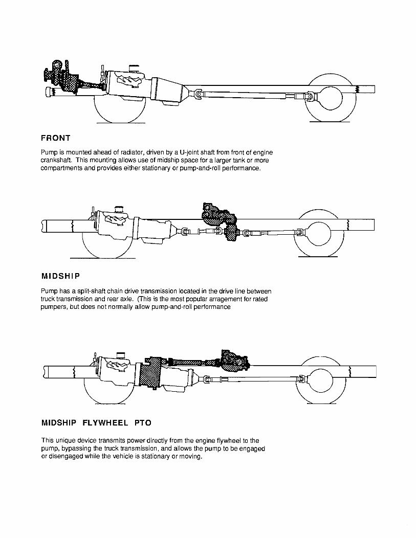
FRONT
Pump is mounted ahead of radiator, driven by a U-joint shaft from front of engine crankshaft. This mounting allows use of midship space for a larger tank or more compartments and provides either stationary or pump-and-roll performance.
MIDSHIP
Pump has a split-shaft chain drive transmission located in the drive line between truck transmission and rear axle. (This is the most popular arragement for rated pumpers, but does not normally allow pump-and-roll performance
MIDSHIP FLYWHEEL PTO
This unique device transmits power directly from the engine flywheel to the pump, bypassing the truck transmission, and allows the pump to be engaged or disengaged while the vehicle is stationary or moving.

PTO
Pump is driven by a transmission -mounted power take-off through a U-joint shaft. Power ratings of PTO's limit size of pump that can be used. Very popular for mini pumpers and tankers. Provides either stationary or pump-and-roll performance.
DIRECT ENGINE MOUNTING
Special adapter permits mounting pump directly on engine bell-housing. Makes a complete unit for mounting, trailer mounting, ect. When used on a pumper this provides the most flexible pump-and-roll performance possible.

w CJ a: <C J: 0 en c
c. :E ::::> c. a: <C w CJ
> a: <C lo a:

OIL
DISCHARGE/
ROTARY VANE PUMP

w CJ a:
c.. < := J: :::> 0 c.. en
c
c.. := :::> c.. ...J < CJ :::> LL a: I-z w 0
< a: 0 LL
a: w ...J
w ...J w en c.. < := 0
c.. w := c..
> :::> I-c.. c w en 0 ...J 0

RELIEF VALVE NOT OPERATING
CONTROL WHEEL CONTROL VALVE BODY"'
'lftv,p:rz:z,70;f/.~
RELIEF VALVE OPERATING

STUDENT INFO PUMP COMPONENTS
FRONT
Pump is mounted ahead of radiator, driven by a U-joint shaft from front of engine crankshaft. This mounting allows use of midship space for a larger tank or more compartments and provides either stationary or pump-and-roll performance.
MIDSHIP
Pump has a split-shaft chain drive transmission located in the drive line between truck transmission and rear axle. (fhis is the most popular arragement for rated pumpers, but does not normally allow pump-and-roll performance
MIDSHIP FLYWHEEL PTO
This unique device transmits power directly from the engine flywheel to the pump, bypassing the truck transmission, and allows the pump to be engaged or disengaged while the vehicle is stationary or moving.

STUDENT INFO PUMP COMPONENTS
PTO
Pump is driven by a transmission -mounted power take-off through a U-joint shaft. Power ratings of PTO's limit size of pump that can be used. Very popular for mini pumpers and tankers. Provides either stationary or pump-and-roll performance.
DIRECT ENGINE MOUNTING
Special adapter permits mounting pump directly on engine bell-housing. Makes a complete unit for mounting, trailer mounting, ect. When used on a pumper this provides the most flexible pump-and-roll performance possible.
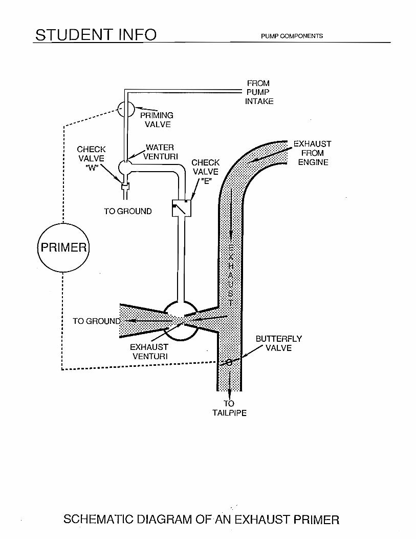
STUDENT INFO PUMP COMPONENTS
-----------
CHECK VALVE
'W'
--
FROM ....------------ PUMP
WATER VENTURI
CHECK VALVE
"E"
INTAKE
TO GROUND
EXHAUST VENTURI
TAILPIPE
BUTTERFLY VALVE
SCHEMATIC DIAGRAM OF·AN EXHAUST PRIMER

STUDENT INFO PUMP COMPONENTS
... DISCHARGE SUCTION
ROTARY GEAR PUMP

STUDENT INFO PUMP COMPONENTS
DISCHARGE/
ROTARY VANE PUMP

STUDENT INFO
PUMP DISCHARGE
,, ,, ,, ,, ,, ,, ,, ,, I/ ,, ,, ,, ,, ,,
PUMP CASE
i, ., '1 ., ,, I\
PUMP COMPONENTS
,, ,, , .... '..:'-..
......... -:.._-..__-_--== =====-=--\ \
\\ ROTATION \\ _.,i._ __ ,, ......... ,, ,, ,, ,, ,, ,, ,,
CLOSED TYPE IMPELLER FOR A CENTRIFUGAL PUMP
Recommended