Proceedings of Acoustics 2012 - Fremantle 21-23 November 2012, Fremantle, Australia
Australian Acoustical Society 1
An experimental study of flow induced vibration of a flexible model riser
Ji Lu (1), Duc K Do (2) and Jie Pan (1)
(1) School of Mechanical and Chemical Engineering, University of Western Australia, WA 6009, Australia (2) Department of Mechanical Engineering, Curtin University of Technology,WA 6102, Australia
ABSTRACT This paper experimentally identifies some non-linear effects, e.g. modal coupling effect and beating motion, on a flexible model riser due to variable curvature when vortex-induced vibration (VIV) occurs. The VIV on the riser can cause enlarging dynamic stress of the body and reducing its fatigure life. This work expands existing numerical and analytical investigations on a model riser with constant curvature in shear flow condition. The results indicate that for a flexible model riser displaced in non-uniform shear flow when VIV occurred, the curvature shows substantial ef-fects on lock-in response and multi-mode non-lock-in response. The modal coupling effect on lock-in response re-peats the same effect on the structure in air, which indicates that modal coupling effect seems independent to the lock-in phenomenon. This experimental investigation embeds the situation when displacing a flexible rubber cable with initial caterany shape stretching its bottom end to most tensioned straight condition for varying the curvature. The ef-fect of varying curvature on the vibration characteristics of the rubber cable is identified when displaced in air. The same effect on the structure when vortex-induced vibration occurred is taken into account through a fan produced wind loading.
INSTRUCTION
Riser for deep water applications are commonly flexible ris-ers and steel catenary risers (SCRs), with large length-to-diameter ratio, slender cross section and curved shape along its length. The riser shape is determined by combination of tension, body weight and buoyancy. Structural vibration of risers is regarded as one of the key sources for enlarging dynamic stress of the body and reducing its fatigue life. Most risers’ vibration disturbances are caused by hydrodynamic disturbance, which is generated by wind, wave and currents. The hydrodynamic disturbance, e.g. flow-induced vibration occurs on the riser when flow passes it and produces fluctuat-ing pressure forces by the wake dynamics (Sarpkaya, 2004).
Previous investigation into the vortex induced vibration (VIV) of bluff-body indicates that there are still needs to understand the relationship between the flow/structure parameters and the forces involved in the fluid-structural interaction (Sarpkaya, 2004). Structural parameters include length-to-diameter ratio, effective stiffness and weight, and curvature. Among them, there seems lack of experimental study on the effect of curvature on the fluid-structural interaction.
For dynamic analysis, the equation of motion of a flexible riser model could be used by modification of the equation of motion of a cable plus two end regions where flexible rigidity is mostly influenced by the boundary conditions (Sparks, 1980). The geometrically exact Kirchhoff beam theory could be used for the cable dynamics (Boyer et al., 2011). The solu-tion for equation of motion of flexible riser often results in non-linear inertia and curvature terms, as well as non-linear terms that couple flexural and torsional motions (Crespo Da Silva and Zaretzky, 1990).
The cross-section of riser structure for investigation is com-monly uniform, and any discontinuity is ignored. The riser structure could be attributed to following types: straight
beams of constant cross-section, beams of constant curvature and constant cross-section, or beams of variable curvature and constant cross-section. Through a parameter study for a cantilever beam of variable curvature and cross-section (Charpie and Burroughs, 1993), it was identified that the natural frequencies of some modes were more sensitive to curvature and mode shapes are coupled. On the other hand, numerical studies on two-dimensional VIV of a Catenary riser revealed an in-plane/out-of-plane modal coupling phe-nomenon, which was attributed to the initial sag and varying curvatures (Srinil et al., 2009). To find out wake dynamics of a cylindrical beam with constant curvature, numerical inves-tigations have been carried out (Miliou et al., 2002, Miliou et al., 2003, Miliou et al., 2007). The simulated model was a pipe in a quarter of circle, disposing in shear and uniform flow at Reynolds number below 1000. It was identified that such curvature structure was able to demonstrate three-dimensional body interactions (Miliou et al., 2003).
Unfortunately, the experimental verification of the flow in-duced vibration of curved structures hasn’t been found. The aforementioned theoretical investigation indicated that the structural curvature may significantly affect the riser dynam-ics. In addition, another interesting effect of curvature should lie on the connection between the curvature terms and other nonlinear terms. For example, one phenomena due to non-linear terms is “beating motion”, which mostly occurs at the first resonance of the structural response (Atadan et al., 1997).
This study focuses on an experimental investigation into the vibration of a flexible cable with variable curvatures and effect of flow-structure interaction on the vibration. The pa-per first introduces the investigation of vibration characteris-tics of the flexible modal riser with variable curvatures (cate-nary shape) displaced in air. After examining the effect of the curvature and some non-linear phenomena, e.g. modal cou-pling effect, the dynamic analysis of the same structure under wind loading when vortex-induced vibration occurs is carried out. From the comparison of the structure with or without

21-23 November 2012, Fremantle, Australia Proceedings of Acoustics 2012 - Fremantle
2 Australian Acoustical Society
lock-in response, the interaction between the curvature term and other non-linear terms are discussed.
RESPONSE OF THE MODEL WITH VARIABLE CURVATURE IN AIR
The model with variable curvature
In this test, a model riser, made by flexible rubber cable, was hanging in the air, with a fixed top end and a variable bottom end. The vertical height of two ends was fixed to 3 m ( zH );
the arc length of two ends was also fixed to 3.5 m (L). The curvature of the model riser can be varied by adjusting the horizontal distance of two ends, from one extreme that the cable is stretched to be a straight line (under tension) to the other extreme that a third point in the cable body starts to touch the ground (without tension). The plane for changing the curvature of the rubber cable is the in-plane, and the plane normal to the in-plane is the out-of-plane. The oscillating response occurred at in-plane or out-of-plane is the in-plane or out-of-plane vibration response.
Figure 1 shows the measured and predicted shape of the rub-ber cable at higher curvature position, where /x zL H is the
ratio of horizontal length to vertical length. The predicted shape is based on catenary equation (Maurer, 1914). The catenary equation, depicting coordinates in Figure 1, for rela-tionship between the vertical distance, y, and horizontal dis-tance, x, is obtained as
),1(cosh −=
a
xay (1)
where a is the catenary factor determined by arc length
).sinh(
a
LaL x= (2)
It can be shown that when xx L= , zy H= .
The differences of measured and calculated curve shapes of the model risers were described by the RMS values of the differences between the measured and predicted vertical dis-tances at all measurement locations (at 25 locations) with respect to L. For case in Figure 1, the calculated ratio is 2.9%.
Figure 2 illustrates the RMS values compared with L (defined as RMS ratios) in terms of /x zL H ratios. The figure indicates
that when /x zL H is less than 0.5 the measured shapes are
quite close to catenary shape with RMS ratio is less than 5%, and can be described by Eq. (1). However, when /x zL H is
larger than 0.5, the curve of the riser is more close to a straight line.
Frequency response of the model with variable cur-vature
To study the vibration characteristics of the model riser with variable curvature, impact hammer test was conducted to measure the frequency response functions of the riser as a function of xL . The test range of xL was from 1.1 m to 1.9 m,
or at /x zL H ratio between 0.4 and 0.633, including distrib-
uted 16 ratios of /x zL H in between. At each ratio, the meas-
urement covers both in-plane and out-of-plane vibration re-sponses of the rubber cable, by applying the impact excitation point slightly offset to the half of the arc length for both in-plane and out-of-plane measurements. Accordingly, the re-
sponse at each direction was measured by an accelerometer located 10 cm above the excitation point. The frequency re-sponse function of the structure at the same locations for both excitation and response were calculated using the measured impact force and riser acceleration.
Figure 1: Geometric shape of the rubber cable at higher cur-
vature position.
Figure 2: RMS ratio of the measured and predicted curves of
the model risers.
(a)
(b)
Figure 3: In-plane (a) and out-of-plane (b) frequency re-sponse functions of the model risers.
0 5 10 15 20 25
0.4
0.45
0.5
0.55
0.6
0.65
8.5
9
9.5
10
10.5
11
Frequency(Hz)
Frequency response of the rubber model at in-plane
Lx/H
Mag
nitu
de(m
/s2/N
)
0 5 10 15 20 25
0.4
0.45
0.5
0.55
0.6
0.65
7
8
9
10
11
Frequency(Hz)
Frequency response of the rubber model at out-of-plane
Lx/H
Mag
nitu
de(m
/s2/N
)

Proceedings of Acoustics 2012 - Fremantle 21-23 November 2012, Fremantle, Australia
Australian Acoustical Society 3
(a)
(b)
Figure 4: In-plane (a) and out-of-plane (b) mode shapes of the rubber cable at /x zL H ratio is 0.467.
Figure 3 shows the in-plane and out-of-plane frequency re-sponse functions of the model risers. As shown in Figure 3(a), a general shift is identified that the resonance peaks of either in-plane or out-of-plane response increases towards high frequency region as /x zL H ratio increases. It is known that
every mode natural frequency is proportional to the square root of stiffness matrix over mass matrix. Due to constant mass matrix at all time, it is reasonable to believe that stiff-ness matrix of the model increases when /x zL H ratio in-
creases or reducing curvature.
After examining the in-plane and out-of-plane structural mo-dal shapes in Figure 4 by applying experimental modal analysis, it is identified that higher modes, e.g. the 4th or 5th mode shows more clearly the trend than the 1st or 2nd mode. It is known that for higher modal frequency, the modal damping becomes larger. When /x zL H ratio increases, Figure 3 indi-
cates that the modal damping for each mode is also affected. As for the 1st and 2nd mode shapes, which are different from that of a straight cable, it is believed that the results for such two modes are partly due to the measurement error, and partly due to the nature of the curved cable. From Figure 3, it is noticed that the 1st and 2nd mode responses are weak re-sponses, and the current excitation method does not provide enough energy to excite the complete mode shapes for such two modes. However, the difference between two mode shapes at in-plane and out-of-plane directions indicates that the out-of-plane response showing high similarity to mode shapes of a straight cable than that of the in-plane response.
Some studies have identified using analytical methods that with changing modal damping ratio of either pair of modes, modal coupling effects could be enhanced or reduced (Zhou and Gu, 2006). Figure 5 shows the modal frequencies of in-plane and out-of-plane responses under single force excita-
tion as a function of /x zL H . The obvious feature is that the
modal frequencies for first 5 modes increase with /x zL H by
either in-plane excitation or out-of-plane excitation. From further study, it is noticed that at higher modes both in-plane and out-of-plane responses share the same modal frequency when /x zL H ratio increases. These higher modes are more
substantial by out-of-plane excitation than in-plane excitation. This feature indicates that when curvature of the structure reduces, the increasing modal damping at higher modes could excite large modal coupling effect on in-plane and out-of-plane response under excitation particularly at out-of-plane direction.
Figure 5: Modal frequencies of the rubber cable under in-plane or out-of plane excitation as a function of curvature.
The other parameter that changes with varying curvature of the structure is the tension at both ends. The tension also has effects on the stiffness of the structure. Vibration to tension force calculation can be achieved: � By the taut string theory that neglects both the sag-
extensibility and the bending stiffness. � Modern cable theory considers the sag-extensibility to
determine the tension force for the given measured vi-bration modes, by considering the sag-to-span ratio of cable, the flexural rigidity and axial rigidity. The ten-sion force can be estimated from the measured funda-mental natural frequency by using approximate analyti-cal closed-form practical formulas (Zui et al., 1996). For a cable with small sag, the tension is proportional to the square of the first natural frequency with a resid-ual; while for a cable with large sag, the tension is pro-portional to the square of the second natural frequency with a residual (Ni et al., 2002).
� By considering shape function, e.g. the catenary equa-tion and /x zL H ratio. Figure 6 shows the force loading
on a catenary shape between AP, where 1T is the cable
tension at point P; 0T is horizontal tension at point A;

21-23 November 2012, Fremantle, Australia Proceedings of Acoustics 2012 - Fremantle
4 Australian Acoustical Society
mg is the gravity force of the cable AP, if s is the cable length between A and P, then sm=µ is the unit mass
per length. Based on Equ.2, ),sinh(a
Las x= and s is a
constant number in our measurements. The following
equations are used to describe 1T and
0T (Nelson et al.,
1952):
., 022
1 gaTasgT µµ =+= (3)
The tension for the rubber cable is calculated based on Equa-tion (3). The computed results for different /x zL H ratio are
illustrated in Figure 7. The difference between the tension at point P and at point A is as large as expected.
After examining the tension in Figure 7, and according to modern cable theory, it is demonstrated that the increased tension is related to the increasing first modal frequency for a cable with small sag, or increasing second modal frequency for a cable with large sag.
Figure 6: Force loading diagram of a catenary shape between
A and P.
Figure 7: Tension of a catenary cable based on the catenary
equation.
THE CABLE RESPONSE AT VARYING FLOW VELOCITIES
Wind loading measurement description
The source of wind loading is a 45 cm high velocity axial floor fan. To maintain the wind loading direction and magni-tude, the setting of the fan and arrangement of the fan to the rubber cable are kept at the same condition when the cable sag is changing. For either in-plane or out-of-plane excitation, the fan is lifted at a same height and kept at the same distance and angle to the rubber cable body when xL is changing. The
wind speed is measured by an Electronic Wind Speed Indica-tor. The fan can reach its rpm within 1 second, so that the
wind loading shifts from 0 to running speed within the 1st second. However at running speed, the fluctuation is also observed. To take into account this fluctuation within meas-urement of each wind loading, a period of 30 seconds con-tinuous full run is captured after the fan is turned on. It is found out that the wind loading at the rubber cable is in the range of 3.6 m/s to 4.42 m/s through averaging 5 measure-ments at the same condition. The Reynolds number of the rubber cable in such wind flow is in the range of 2915 to 3580, indicating a turbulent flow situation. The reduced mass of the rubber cable is 438.
Evidence of vortex-induced vibration
From the Strouhal number-Reynolds number relationship (Roshko, 1955), the following equation can be used to obtain the Strouhal number (Shi et al., 2011)
St = 0.191(1−169.6/Re), for 200 < Re < 5,000. (4)
Therefore, the range of Strouhal number is at 0.179 to 0.182. Figure 8 illustrates the in-line and cross-flow response at 52.8% of the arc length from the bottom and /x zL H ratio when
wind loading applied at in-plane. When vortex-induced vibra-tion occurs, the oscillation frequency of the structure locks in to the vortex shedding frequency. The vortex shedding fre-quency is determined by
.min
d
StUfs = (5)
The applied Strouhal number (St) is 0.179, flow velocity
( minU ) is 3.6 m/s, and diameter of the cable (d) is 0.0127 m.
Therefore, the theoretical shedding frequency is 50.7 Hz. Figure 8 indicates that two response modes of the cable are excited; for Mode k the frequency is 45.31 Hz, and Mode k-1 is 22.66 Hz (Mode k-1 in both plots of Figure 8 has the same frequency). The ratio between the mode k and shedding fre-quency is closed to 1 and the ratio between mode k and mode k-1 is 2. Besides, the reduced velocity at current measure-ment is between 6.3 and 7.68. Therefore, the structure is syn-chronized. When the rubber cable is excited by wind loading at out-of-plane, vortex-induced vibration is also observed in Figure 10 for /x zL H =0.4.
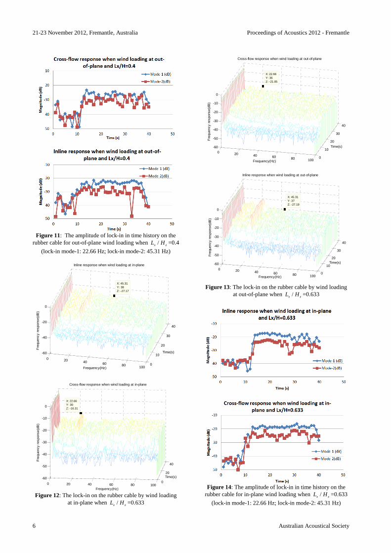
The amplitude of responses during lock-in for the rubber cable at this /x zL H ratio is listed in Figure 9 (in-plane load-
ing) and Figure 11 (out-of-plane loading). For different /x zL H ratios, the arrangement of the fan to the rubber cable
are kept at the same condition, which means the direction and magnitude of wind loading on the rubber cable are the same. Figure 12 and Figure 13 present the rubber cable response due to in-plane or out-of-plane wind loading when /x zL H
=0.633. Figure 14 and Figure 15 show the amplitude of re-sponses of the structure under in-plane loading and out-of-plane loading. As a result, both extreme /x zL H ratios of the
rubber cable displaced in Section 2 are examined in wind loading experiments and vortex-induced vibration can be expected at every /x zL H ratio.
Discussion and analysis
The wind loading can be treated as mild shear, as the ratio of the shear fraction for the fan flow is ∆V V��� = 10%⁄ , in the range for mild shear that below 20%. According to the litera-ture (Vandiver et al., 1996), the multi-mode non-lock-in re-

Proceedings of Acoustics 2012 - Fremantle 21-23 November 2012, Fremantle, Australia
Australian Acoustical Society 5
sponse could be examined on the structure at such flow con-dition. From Figure 8 and Figure 10, this kind of response is observed for wind loading at out-of-plane with /x zL H =0.4,
but hardly noticeable for wind loading at in-plane. From Fig-ure 12 and Figure 13, for the rubber cable withholding high-est tension, it is identified that the lock-in response and non-lock-in response are both enhanced whether at in-plane load-ing or at out-of-plane loading. Therefore, it is possible to summarize that with less curvature of the structure, and in-creased tension at the boundary, both lock-in response and multi-mode non-lock-in response are enhanced.
During the lock-in at two extreme /x zL H ratios, the lock-in
frequency is unchanged. Comparing to the in-plane response and out-of-plane response at lock-in frequency, the ratio of two response values is far above 10%, indicating the princi-ple response and transverse response are not due to transverse sensitivity of the accelerometers. Besides, the fan flow is strictly displaced at in-plane or out-of-plane of the rubber cable for in-plane or out-of-plane excitation. As a result, the error of accelerometer position to the flow direction can be ignored.
Figure 8: The lock-in on the rubber cable by wind loading at in-plane when /x zL H =0.4
The lock-in amplitude, shown in Figure 9, 11, 14 and 15, indicates that between two extreme /x zL H ratios, the modal
coupling effect on lock-in response amplitude for wind load-ing at out-of-plane is more dominate when the curvature of the structure decreases.
Meanwhile, beating motion, e.g. amplitude oscillation in Figure 11(a), is clearly observed on the amplitude response when /x zL H =0.4, but only obvious on the structure under
out-of-plane wind loading when /x zL H =0.633. It is possible
to predict that beating motion is most dominate in out-of-plane force, but with increasing curvature, this phenomenon can be enhanced and occurred under in-plane force.
Figure 9: The amplitude of lock-in in time history on the rubber cable for in-plane wind loading when /x zL H =0.4
(lock-in mode-1: 22.66 Hz; lock-in mode-2: 45.31 Hz)
Figure 10: The lock-in on the rubber cable by wind loading at out-of-plane when /x zL H =0.4
0 20 40 60 80 1000
10
20
30
40
-60
-50
-40
-30
-20
-10
0
Time(s)
Frequency(Hz)
Inline response when wind loading at in-plane
X: 45.31Y: 37Z: -24.88
Fre
quen
cy r
espo
nse(
dB)
0 20 40 60 80 1000
10
20
30
40
-60
-50
-40
-30
-20
-10
0
Time(s)
Frequency(Hz)
Cross-flow response when wind loading at in-plane
X: 22.66Y: 38Z: -31.39
Fre
quen
cy r
espo
nse(
dB)
0 20 40 60 80 1000
10
20
30
40
-60
-50
-40
-30
-20
-10
0
Time(s)
Frequency(Hz)
Cross-flow response when wind loading at out-of-plane
X: 22.66Y: 32Z: -27.11
Fre
quen
cy r
espo
nse(
dB)
0 20 40 60 80 1000
10
20
30
40
-80
-60
-40
-20
0
Time(s)
X: 45.31Y: 35Z: -27.47
Frequency(Hz)
Inline response when wind loading at out-of-plane
Fre
quen
cy r
espo
nse(
dB)
21-23 November 2012, Fremantle, Australia Proceedings of Acoustics 2012 - Fremantle
6 Australian Acoustical Society
Figure 11: The amplitude of lock-in in time history on the
rubber cable for out-of-plane wind loading when /x zL H =0.4
(lock-in mode-1: 22.66 Hz; lock-in mode-2: 45.31 Hz)
Figure 12: The lock-in on the rubber cable by wind loading
at in-plane when /x zL H =0.633
Figure 13: The lock-in on the rubber cable by wind loading
at out-of-plane when /x zL H =0.633
Figure 14: The amplitude of lock-in in time history on the
rubber cable for in-plane wind loading when /x zL H =0.633
(lock-in mode-1: 22.66 Hz; lock-in mode-2: 45.31 Hz)
0 20 40 60 80 1000
10
20
30
40
-60
-40
-20
0
Time(s)
X: 45.31Y: 38Z: -27.17
Inline response when wind loading at in-plane
Frequency(Hz)
Fre
quen
cy r
espo
nse(
dB)
0 20 40 60 80 1000
20
40
-60
-50
-40
-30
-20
-10
0
Time(s)
Frequency(Hz)
Cross-flow response when wind loading at in-plane
X: 22.66Y: 30Z: -16.31
Fre
quen
cy r
espo
nse(
dB)
0 20 40 60 80 1000
10
20
30
40
-60
-50
-40
-30
-20
-10
0
Time(s)
Cross-flow response when wind loading at out-of-plane
Frequency(Hz)
X: 22.66Y: 36Z: -21.05
Fre
quen
cy r
espo
nse(
dB)
0 20 40 60 80 1000
10
20
30
40
-60
-50
-40
-30
-20
-10
0
Time(s)
X: 45.31Y: 37Z: -27.19
Frequency(Hz)
Inline response when wind loading at out-of-plane
Fre
quen
cy r
espo
nse(
dB)

Proceedings of Acoustics 2012 - Fremantle 21-23 November 2012, Fremantle, Australia
Australian Acoustical Society 7
Figure 15: The amplitude of lock-in in time history on the rubber cable for out-of-plane wind loading when /x zL H
=0.633 (lock-in mode-1: 22.66 Hz; lock-in mode-2: 45.31 Hz)
CONCLUSION
This study investigates the curvature effect for the dynamic response of the flexible model riser in air and in non-uniform shear flow when VIV occurs. The results can improve the understanding about non-linear phenonmen of VIV, and eventually providing the necessary evidence for exsitng and further approaches to improve the fatigure life of the struc-ture.
When the structure displaced in air with curvature decreasing from a closely catenary shape to a tensioned linear shape, it was found out that the tension at the boundary is increased due to reducing curvature. The increased tension could show substantial effects of stiffness matrix of the structure, the modal damping and modal coupling effect.
When the flexible model riser displaced in non-uniform shear flow when VIV occurred, the curvature shows substantial effects on lock-in response and multi-mode non-lock-in re-sponse. The modal coupling effect on lock-in response re-peats the same effect on the structure in air, which indicates that modal coupling effect seems independent to the lock-in phenomenon. Beating motion, however, shows some rela-tionship to curvature, and is widely observed on response amplitude for out-of-plane force.
REFERENCES
Atadan, AS, et al. 1997. Analytical and numerical analysis of the dynamics of a marine riser connected to a floating platform. Ocean Engineering, 24, 111-131.
Boyer, F, et al. 2011. Geometrically exact Kirchhoff beam theory: application to cable dynamics. Journal of Computational and Nonlinear Dynamics, 6, 041004-041017.
Charpie, JP & Burroughs, CB 1993. An analytic model for the free in-plane vibration of beams of variable curvature
and depth. Journal of Acoustical Society of America, 94, 866-879.
Crespo Da Silva, MRM & Zaretzky, CL 1990. Non-linear modal coupling in planar and non-planar responses of inextensional beams International Journal of Non-Linear Mechanics, 25, 227-239.
Maurer, ER 1914. Technical mechanics, J. Wiley & Sons. Miliou, A, et al. 2007. Wake dynamics of external flow past a
curved circular cylinder with the free stream aligned with the plane of curvature Journal of Fluid Mechanics, 592, 89-115.
Miliou, A, et al. 2002. Three-dimensional wakes of curved pipes. OMAE2002. Oslo, Norway.
Miliou, A, et al. 2003. Fluid dynamic loading on curved riser pipes. Journal of Offshore Mechanics and Arctic Engineering, 125, 176-182.
Nelson, AL, et al. 1952. Differential equations, Boston, D.C. Heath & Co,.
Ni, YQ, et al. 2002. Dynamic analysis of large-diameter sagged cables taking into account flexural rigidity. Journal of Sound and Vibration, 257, 301-319.
Roshko, A 1955. On the wake and drag of bluff bodies. Journal of the Aeronautical Sciences, 22, 124-132.
Sarpkaya, T 2004. A critical review of the intrinsic nature of vortex-induced vibrations Journal of Fluids and Structures, 19, 389-447.
Shi, L, et al. 2011. Investigation into the Strouhal Numbers associated with vortex shedding from parallel-plate thermoacoustic stacks in oscillatory flow conditions. European Journal of Mechanics - B/Fluids, 30, 206-217.
Sparks, CP 1980. Mechanical behavior of marine risers mode of influence of principle parameters. Journal of Energy Resources Technology, 102, 214-222.
Srinil, N, et al. 2009. Reduced-order modeling of vortex-induced vibration of catenary riser. Ocean Engineering, 36, 1404-1414.
Vandiver, JK, et al. 1996. The occurrence of lock-in under highly sheared conditions. Journal of Fluids and Structures, 10, 555-561.
Zhou, XY & Gu, M 2006. Analytical approach considering modal coupling effects for buffeting resonant response of large-span roof structures. Journal of Vibration Engineering, 19, 179-183.
Zui, H, et al. 1996. Practical formulas for estimation of cable tension by vibration method. Journal of Structural Engineering, 122, 651-656.
Recommended