
*.U.S. Patent No. 7,546,987, Patents Pending
PRO-10PRO-10 SERIES CATALOG
2012-2013
®
™

WIREMAID, PRO-10, and The Safest Solution, are trademarks of Vutec Corporation, UL and UL Classified are certification marks of Underwriters Laboratories Inc.
“The One -Tool System”
• Maintains UL Classification
• Reduces Installation Time by 50% or More
• Large Load Tested Capacity
• UL Bonding & Splicing built-in
• Powder Coat Finish is standard
• Code Compliance
NO FIELD CUTTING OR BENDING REQUIRED
®
™
PRO-10™ Cable tray system is recognized by contractors and engineers as the preferred cable management system that adapts to the most difficult installations providing a cost-effective solution.

www.wiremaidusa.com
Why PRO-10 Cable Tray by CABLE-MGR®
CABLE-MGR® introduces PRO-10 Cable Trays, the One-Tool System™,
recognized by contractors and engineers as the premier cable tray
system with the lowest installed cost. PRO-10 Cable Tray is a complete
line of factory built turns and fittings that creates a 100% NEC Compliant
Cable Tray System. PRO-10™ fittings connected to a PRO-10™ straight
section maintains 100% UL® Classification that fully complies with NEC.
PRO-10's built-in splice is also UL classified for bonding, assuring the
job is done right the first time, every time. The patented One-Tool
System™ reduces installation time by 50% or more and adapts to the
most difficult installations.
About Wiremaid
Since 1950, WIREMAID® has designed and manufactured wire products for commerce and industry. WIREMAID is the leader in the design and manufacture of wire mesh cable trays branded CABLE-MGR® as well as safety guards for lighting fixtures, fans, and equipment. Our products are manufactured in the USA using eco-friendly recyclable materials.
WIREMAID's product line is designed for ease of installation, safety and value. Dedicated to service and excellence in workmanship, WIREMAID continually strives to be at the vanguard of its industry.
800-770-4700 I www.wiremaidusa.com
Table of Contents
3
Introduction
Introduction.........................................3
Features & Benefits...........................4
Cable Tray Layout.............................. 5 Tray Cross Sections..............................5
Products....................................................6-8
Mounting Supports & Hardware ............9-10 Accessories & J-Tray..........................11
Load & Fill Chart.................................12
Cable Tray Weights............................13
PRO-Hanger Ceiling Suspension.......14
Installation...........................................15
Page
®
™

4
PRO-10™ is available in wire diameter choices CM10 (Ø.120) and CM20 (Ø.187) – to accommodate various cable tray load capacities. No cutting or bending, is required on any of these styles.
The CM20 cable tray, with a grid pattern of 2”x 4", is the standard for commercial and industrial cabling applications. CM20 is powder coated and available in variety of widths; lengths of 1’, 2’, 5’, 8’ or 10’ and depths of 2”, 4”, 6” or custom.
CM10, superior cable management support system with a 2”x 2” grid pattern, is the lightweight solution for fiber optic cabling and cable management that minimizes cable sagging or dropping. CM10 comes in widths of 2”, 4”, 6”, or 8”; lengths of 1’, 2’, and 5' with depths of 2"or 4".
• Requires NO bending or cutting; factory–made “4-way” crossroads, “T”, 90°, 45°, 30° horizontal and elevation changes as well as 1',2',5',8',10' lengths.
• Acts as an equipment ground conductor (NEC 392.60)
• No bonding jumpers required for NEC compliance
• Adapts to difficult architectural designs to accommodate changes in direction and elevation of cable runs
• Reduces installation time with the One-Tool System™
• Provides strength and rigidity without additional hardware
• Manufactured with protective powder coated colored finishes avoiding corrosion and Zinc Whiskers.
• Manufactured with 95% Eco-Friendly recycled materials
• Custom sizes available
• U.S. Patent No. 7,546,987
Cable Tray
Features of
Benefits of
PRO-10™ cable trays and accessories are available for quick delivery from stock. PRO-10™ is made in the U.S.A., shortening lead and delivery time. For special applications, our customer service representatives are eager to help in design and product expediting. Warranty one year for replacement parts.
Contact Customer Service at:
800-770-4700 I www.wiremaidusa.com
Technical Support
www.wiremaidusa.com
®
™

Call Toll Free 800.770.4700 or [email protected]
5
Typical Cable Tray Layout
®
™
Reducer
T FittingL Fitting
Straight Section
4-Way Fitting
Elevation Change
24”
18”
12”
8”
6”
4”
2”
36”
45° Fitting
30° Fitting
Waterfall
1' ,2' ,5', 8', 10'
Widths available
Lengths available

6
Catalog Numbering System
Powder Coat Finish Chart
CM 20 Straight CM 29 Reducers05 - 20 08 2 10 3 05 - 29 12X08 4 1
Tray Width6” = 068” = 0812” = 1218” = 1824” = 2436” = 36
Tray Reduction6”- 4” = 06X048”- 6” = 08X0612”- 8” = 12X08 18”-24” = 18X24 24”-18” = 24X18
Tray FinishSafety Yellow = 1
White = 2Chrome = 3
Black = 4Red = 5Blue = 6
Orange = 10
Tray FinishSafety Yellow = 1
White = 2Chrome = 3
Black = 4Red = 5Blue = 6
Orange =10
Tray Depth2” = 024” = 046” = 06
Tray Depth2” = 024” = 046” = 06
Tray Length1’ = 012’ = 025’ = 058’ = 08
10’ = 10
CM 20 Straight Sections CM 29 Reducer
Reducers are available in standard configurations with a depth/height of 2”, 4” or 6” ( 24”-18”, 18”-12”, 12”- 8” and 8”- 6” are standard). See finish chart below for standard colors. Custom colors and sizes available. Includes interconnecting hardware.
Straight sections (Ø.187) have a grid pattern of 2” x 4” and are available in standard widths of 2", 4",6”, 8”, 12”, 18”, 24” and 36”. Lengths can be ordered in 1’, 2’, 5’, 8’ and 10’ with a depth/height of either 2”, 4” or 6”.
All sections are UL classified.
See finish chart below. Custom sizes and colors are available. Sections include interconnecting hardware.
Check load and fill ratio chart (pg. 12) for requirements
Yellow - 1 Black - 4 White - 2 Red - 5 Chrome - 3 Blue - 6 Orange - 10
“Straight”
www.wiremaidusa.com
CM 25 Fitting05 - 25 18 2 T 2
Tray FinishSafety Yellow = 1
White = 2Chrome = 3
Black = 4Red = 5Blue = 6
Orange = 10Tray Depth2” = 024” = 046” = 06
Fitting TypeT = T Fitting
X = 4-Way FittingL = L Fitting
E C = Elevation Change30 ° = 3045 ° = 45
Pre-fabricated fittings (Ø.187) are available in standard widths of a depth/height of 2”, 4” or 6”.
See finish chart below for colors. Custom colors are available. Includes interconnecting hardware.
Tray Width6” = 068” = 0812” = 1218” = 1824” = 2436” = 36
“45° Fitting”
CM 25 Fittings
“Reducer”
®
™
ProductsCM20, CM25, and CM29 are UL classified

Powder Coat Finish Chart
Yellow - 1 Black - 4 White - 2 Red - 5 Chrome - 3 Blue - 6 Orange - 10
7
Call Toll Free 800.770.4700 or [email protected]
®
™
"L" Fittings
"4-Way" Fittings
"T" Fittings
Elevation Change
CM 10 Cross Sections
2" 4"
2"
4" 6"
CM 20 Cross Sections
Products
8
Products
Powder Coat Finish Chart
Yellow - 1 Black - 4 White - 2 Red - 5 Chrome - 3 Blue - 6 Orange - 10
www.wiremaidusa.com
®
™
Installation
Catalog Numbering System
CM 15 Fittings
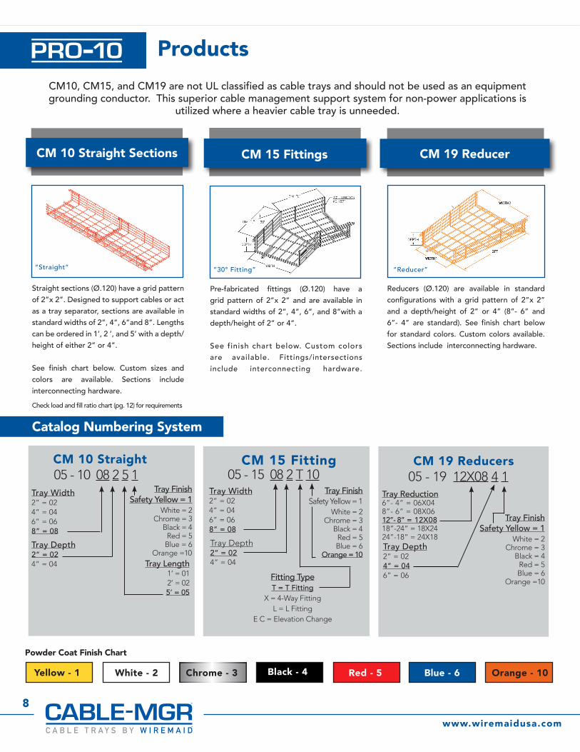
CM 15 Fitting05 - 15 08 2 T 10
Tray Width2” = 024” = 046” = 068” = 08
Tray FinishSafety Yellow = 1
White = 2Chrome = 3
Black = 4Red = 5Blue = 6
Orange = 10Tray Depth2” = 024” = 04
Fitting TypeT = T Fitting
X = 4-Way FittingL = L Fitting
E C = Elevation Change
Pre-fabricated fittings (Ø.120) have a grid pattern of 2”x 2” and are available in standard widths of 2”, 4”, 6”, and 8”with a depth/height of 2” or 4”.
See finish chart below. Custom colors are available. Fittings/intersections include interconnecting hardware.
“30° Fitting”Installation
CM 10 Straight Sections
CM 10 Straight 05 - 10 08 2 5 1
Tray Width2” = 024” = 046” = 068” = 08
Tray FinishSafety Yellow = 1
White = 2Chrome = 3
Black = 4Red = 5
Blue = 6 Orange =10
Tray Depth2” = 024” = 04 Tray Length
1’ = 012’ = 025’ = 05
Straight sections (Ø.120) have a grid pattern of 2”x 2”. Designed to support cables or act as a tray separator, sections are available in standard widths of 2”, 4”, 6”and 8”. Lengths can be ordered in 1’, 2 ’, and 5’ with a depth/height of either 2” or 4”.
See finish chart below. Custom sizes and colors are available. Sections include interconnecting hardware.
Check load and fill ratio chart (pg. 12) for requirements
“Straight”
CM 19 Reducers05 - 19 12X08 4 1
Tray Reduction6”- 4” = 06X048”- 6” = 08X0612”- 8” = 12X08 18”-24” = 18X24 24”-18” = 24X18
Tray FinishSafety Yellow = 1
White = 2Chrome = 3
Black = 4Red = 5Blue = 6
Orange =10
Tray Depth2” = 024” = 046” = 06
Reducers (Ø.120) are available in standard configurations with a grid pattern of 2”x 2” and a depth/height of 2” or 4” (8”- 6” and 6”- 4” are standard). See finish chart below for standard colors. Custom colors available. Sections include interconnecting hardware.
CM 19 Reducer
“Reducer”
CM10, CM15, and CM19 are not UL classified as cable trays and should not be used as an equipment grounding conductor. This superior cable management support system for non-power applications is
utilized where a heavier cable tray is unneeded.

Mounting Supports & Hardware Kits
9
Call Toll Free 800.770.4700 or [email protected]
Center Support Kit Installation Hardware
Trapeze Support Kit Installation Hardware
Trapeze Support
Pedestal Angle Support Kit
05-CM75-3 Raised Floor Pedestal Bridge Support Kit - includes:(1) Bridge Support and
(2) “U” ClampsSpans 24 inch center to center floor pedestals up to a
1-1/2” diameter
Center Support Kit
Pedestal Bridge Support Kit
All connection hardware is included for each tray section and not required to be ordered separately.
CM50xx-x ¼” Threaded Rod Kit. Includes (1) support bracket (1) hold down bracket (2) ¼” flat washers (2) ¼” nuts (1) 6” protective tubes. Threaded Rod not included.
CM51xx-x ⅜” Threaded Rod Kit. Includes (1) support bracket (1) hold down bracket (2) ⅜” flat washers (2) ⅜” nuts (1) 6” protective tubes. Threaded Rod not included.
CM52xx-x ¼” Threaded Rod Kit. Includes (1) support bracket (1) hold down bracket (2) ¼” finned nuts (4) ¼” flat washers (4) ¼” nuts. Threaded Rod not included.
CM53xx-x ⅜” Threaded Rod Kit. Includes (1) support bracket (1) hold down bracket (2) ⅜” finned nuts (4) ⅜” flat washers. (4) ⅜” nuts. Threaded Rod not included.
Ø.250
.25" rod P/N Width05-5002-X 2”05-5004-X 4”05-5006-X 6”05-5008-X 8”05-5012-X 12”05-5018-X *18”05-5024-X *24”05-5036-X *36”
.375" rod P/N Width
05-5106-X 6”05-5108-X 8”05-5112-X 12”05-5118-X *18”05-5124-X *24"05-5136-X *36"
Ø.250**4” height
P/N Width
05-5602-X 2”05-5604-X 4”05-5606-X 6”05-5608-X 8”05-5612-X 12”05-5618-X 18”05-5624-X 24”05-5636-X 36”
** other heights available
* 18" & larger are built from heavy duty framing strut to accommodate heavier loads
* 18" & larger are built from heavy duty framing strut to accommodate heavier loads
* 18" & larger are built from heavy duty framing strut to accommodate heavier loads
Under Floor Mount Support
Clamps fit up to a 1-1/2" dia. Pedestal
05-CM75-3 includes:(2) Angle Supports(2) "U" Clamps
Ø.250
.25" rod P/N Width05-5206-X 6”05-5208-X 8”05-5212-X 12”05-5218-X *18”05-5224-X *24”05-5236-X *36”
.375" rod P/N Width
05-5306-X 6”05-5308-X 8”05-5312-X 12”05-5318-X *18"05-5324-X *24”05-5336-X *36"
Cable Tray Support
"L" P/N Tray Width05-CM18-04201 6”05-CM18-04202 8”05-CM18-04205 12”05-CM18-4208 *18”05-CM18-XXXX *24”05-CM18-XXXX *36”
"C" P/N Tray Width05-CM24-04201 6”05-CM24-04202 8”05-CM24-04205 12”05-CM24-04208 18”05-CM24-XXXX 24”05-CM24-XXXX 36"
“L Support” “C Support”
Wall Mount Support
Ø.250
P/N Width05-5702-X 2”05-5704-X 4"05-5706-X 6”05-5708-X 8”05-5712-X 12”05-5718-X *18”05-5724-X *24”05-5736-X *36”
®
™

10
Mounting Supports & Hardware Kits
Solid Bottom
Hold Down Bracket
Splice Washer Kit
Cable Tray Divider
Cable Tray Cover
• Powder coated to provide a smooth protective surface for cable pulling• Can be supplied pre-assembled to cable trays or installed in the field. #05-2-500985 Splice Washer Assembly, 4/plate, included• Available in easy to handle 59” lengths• Fits cable trays 6, 8, 12, 18 and 24 inches wide
#05-2-500982 Used to secure tray sections to all supports. Material is steel wire powder coated chrome color 4” long.
#05-2-600726
PRO-10™ Connecting hardware included with traysThe cable tray straight and junction sections are easily joined together using installer-friendly splice washer kits. The kit contains one ¼”- 20 bolt washer, one splice washer, and one flanged hex nut. Material is zinc plated steel.
#05-2-500983 for a 2” deep tray#05-2-500984 for a 4” deep trayDividers are made from powder coated steel and are 5’ long.(Two Splice Washer Assembly Kits #05-2-500985 used to secure to each tray section included.)
Hold down included with all wall, floor, and ceiling supports. Order extras only.
www.wiremaidusa.com
P/N Size (WxL)
05-2-06BP 6" x 59”
05-2-08BP 8" X 59”
05-2-12BP 12" X 59”
05-2-18BP 18" X 59”
05-2-24BP 24" X 59”
05-2-36BP 36" X 59"
P/N Size (WxL)
05-CM21-06 6" x 59”
05-CM21-08 8" X 59”
05-CM21-12 12" X 59”
05-CM21-18 18" X 59”
05-CM21-24 24" X 59”
05-CM21-26 36" X 59"
®
™
11
Call Toll Free 800.770.4700 or [email protected]
#05-2-0600727
#05-2-0600728 Ratchet CM99
6" Protective Steel Tubingfor ¼”& ⅜”
threaded rodCM69
Ground Bolt
Beam Clamp
Cable Tray Cutter
J-TrayAccessories
Coupling Nuts¼”- 20 CM60⅜”-16 CM61
Flat Washers¼” CM62⅜” CM63
Finned Nuts¼”- 20 CM65⅜”-16 CM665/16”-18 CM67
Carriage Bolts5/16”-18 x ¾” CM68
5/16”-18 x 1-¼” CM72
Tray Extension Offset Loop
P/N05-59-X...........
05-CM58........
05-CM60........
05-CM61........
05-CM7002....
05-CM100......
05-CM101......
ITEMWaterfall 4”
Tray Ext. Loop
Coupling Nut -¼”- 20
Coupling Nut - ⅜”-16
Universal Loop .187”
Beam Clamp ¼” thd rod
Beam Clamp ⅜” thd rod
#CM100 ¼” thd rod #CM101 ⅜” thd rod
CM58
Ø.187
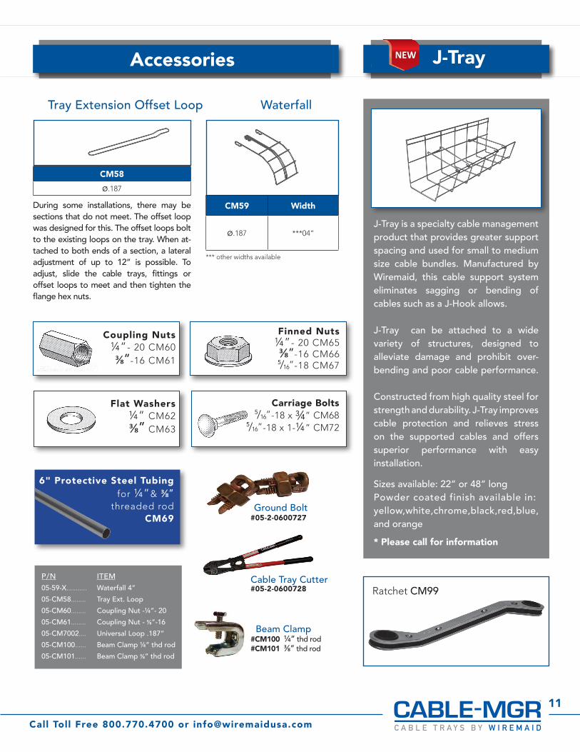
During some installations, there may be sections that do not meet. The offset loop was designed for this. The offset loops bolt to the existing loops on the tray. When at-tached to both ends of a section, a lateral adjustment of up to 12” is possible. To adjust, slide the cable trays, fittings or offset loops to meet and then tighten the flange hex nuts.
Waterfall
CM59 Width
Ø.187 ***04”
*** other widths available
J-Tray is a specialty cable management product that provides greater support spacing and used for small to medium size cable bundles. Manufactured by Wiremaid, this cable support system eliminates sagging or bending of cables such as a J-Hook allows.
J-Tray can be attached to a wide variety of structures, designed to alleviate damage and prohibit over-bending and poor cable performance.
Constructed from high quality steel for strength and durability. J-Tray improves cable protection and relieves stress on the supported cables and offers superior performance with easy installation. Sizes available: 22” or 48” long Powder coated finish available in:yellow,white,chrome,black,red,blue, and orange
* Please call for information
NEWNEW
®
™
Load & Fill Chart
12
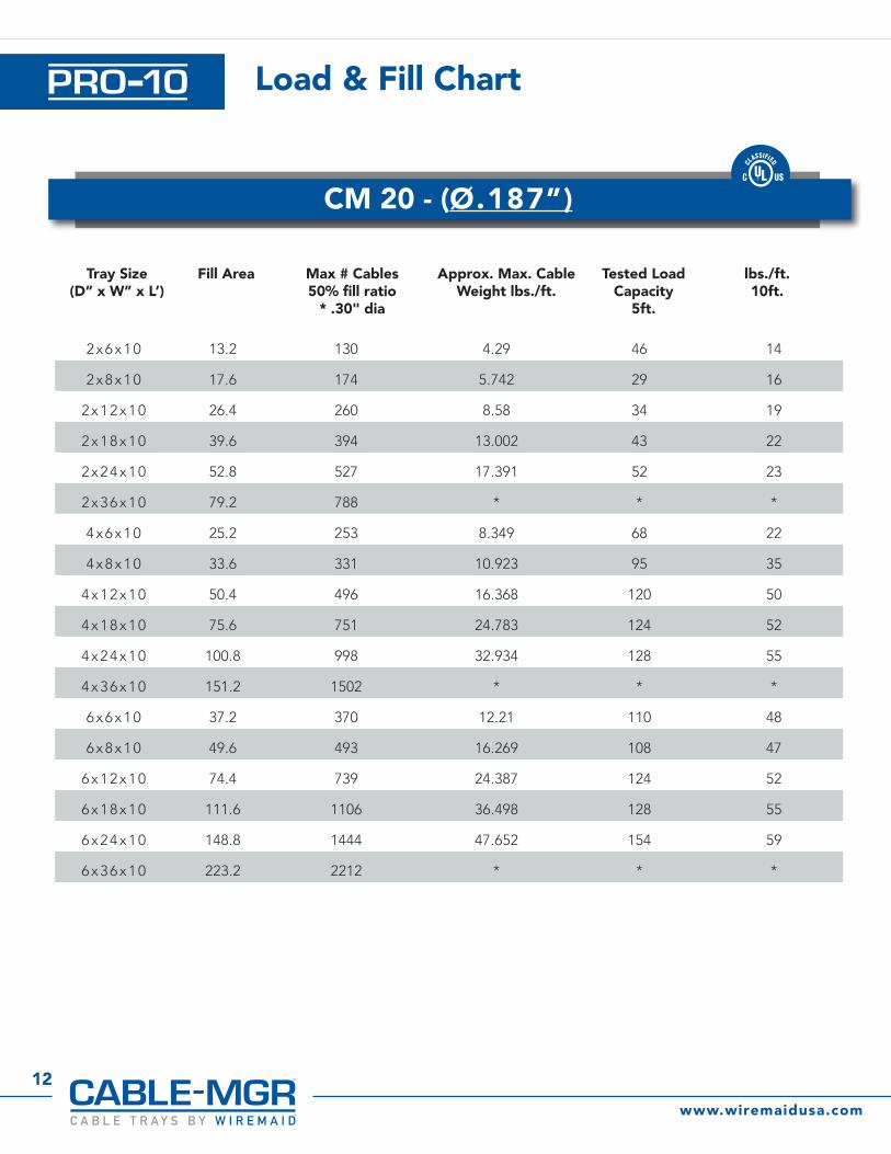
2 x 6 x 1 0 13.2 130 4.29 46 14
2 x 8 x 1 0 17.6 174 5.742 29 16
2 x 1 2 x 1 0 26.4 260 8.58 34 19
2 x 1 8 x 1 0 39.6 394 13.002 43 22
2 x 2 4 x 1 0 52.8 527 17.391 52 23
2 x 3 6 x 1 0 79.2 788 * * *
4 x 6 x 1 0 25.2 253 8.349 68 22
4 x 8 x 1 0 33.6 331 10.923 95 35
4 x 1 2 x 1 0 50.4 496 16.368 120 50
4 x 1 8 x 1 0 75.6 751 24.783 124 52
4 x 2 4 x 1 0 100.8 998 32.934 128 55
4 x 3 6 x 1 0 151.2 1502 * * *
6 x 6 x 1 0 37.2 370 12.21 110 48
6 x 8 x 1 0 49.6 493 16.269 108 47
6 x 1 2 x 1 0 74.4 739 24.387 124 52
6 x 1 8 x 1 0 111.6 1106 36.498 128 55
6 x 2 4 x 1 0 148.8 1444 47.652 154 59
6 x 3 6 x 1 0 223.2 2212 * * *
www.wiremaidusa.com
CM 20 - (Ø.187”)
®
™
Tray Size(D” x W” x L’)
Fill Area Max # Cables50% fill ratio
* .30" dia
Approx. Max. CableWeight lbs./ft.
Tested Load Capacity
5ft.
lbs./ft.10ft.
13
Call Toll Free 800.770.4700 or [email protected]
Cable Tray Weights
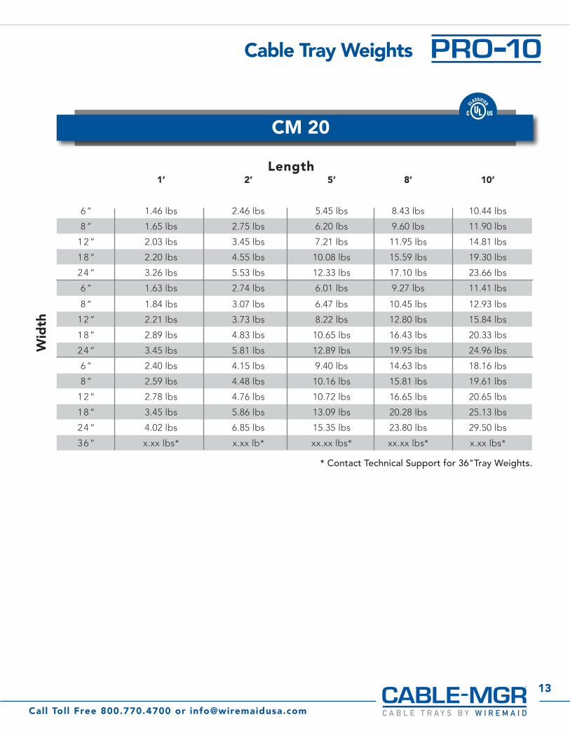
1’ 2’ 5’ 8’ 10’
6 ” 1.46 lbs 2.46 lbs 5.45 lbs 8.43 lbs 10.44 lbs
8 ” 1.65 lbs 2.75 lbs 6.20 lbs 9.60 lbs 11.90 lbs
1 2 ” 2.03 lbs 3.45 lbs 7.21 lbs 11.95 lbs 14.81 lbs
1 8 ” 2.20 lbs 4.55 lbs 10.08 lbs 15.59 lbs 19.30 lbs
2 4 ” 3.26 lbs 5.53 lbs 12.33 lbs 17.10 lbs 23.66 lbs
6 ” 1.63 lbs 2.74 lbs 6.01 lbs 9.27 lbs 11.41 lbs
8 ” 1.84 lbs 3.07 lbs 6.47 lbs 10.45 lbs 12.93 lbs
1 2 ” 2.21 lbs 3.73 lbs 8.22 lbs 12.80 lbs 15.84 lbs
1 8 ” 2.89 lbs 4.83 lbs 10.65 lbs 16.43 lbs 20.33 lbs
2 4 ” 3.45 lbs 5.81 lbs 12.89 lbs 19.95 lbs 24.96 lbs
6 ” 2.40 lbs 4.15 lbs 9.40 lbs 14.63 lbs 18.16 lbs
8 ” 2.59 lbs 4.48 lbs 10.16 lbs 15.81 lbs 19.61 lbs
1 2 ” 2.78 lbs 4.76 lbs 10.72 lbs 16.65 lbs 20.65 lbs
1 8 ” 3.45 lbs 5.86 lbs 13.09 lbs 20.28 lbs 25.13 lbs
2 4 ” 4.02 lbs 6.85 lbs 15.35 lbs 23.80 lbs 29.50 lbs
3 6 ” x.xx lbs* x.xx lb* xx.xx lbs* xx.xx lbs* x.xx lbs*
Length
Wid
th
CM 20
* Contact Technical Support for 36"Tray Weights.
®
™
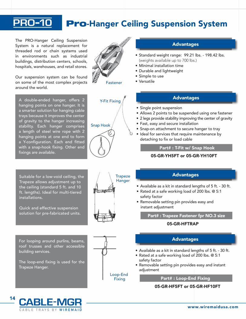
Fastener
Trapeze Hanger
Loop-End Fixing
Y-Fit Fixing
Snap Hook
Advantages
Advantages
Part# : T-Fit w/ Snap Hook
05-GR-YH5FT or 05-GR-YH10FT
05-GR-HFTRAP
05-GR-HF5FT or 05-GR-HF10FT
Part# : Trapeze Fastener fpr NO.3 size
Part# : Loop-End Fixing
Advantages
Advantages
• Standard weight range: 99.21 lbs. - 198.42 lbs. (weights available up to 700 lbs.)
• Minimal installation time• Durable and lightweight • Simple to use• Versatile
• Available as a kit in standard lengths of 5 ft. - 30 ft.• Rated at a safe working load of 200 lbs. @ 5:1
safety factor• Removable setting pin provides easy and
instant adjustment
• Available as a kit in standard lengths of 5 ft. - 30 ft.• Rated at a safe working load of 200 lbs. @ 5:1
safety factor• Removable setting pin provides easy and instant
adjustment
• Single point suspension • Allows 2 points to be suspended using one fastener• 2 legs provide stability improving the center of gravity• Fast, easy and secure installation• Snap-on attachment to secure hanger to tray• Ideal for services that require maintenance by
detaching to fix or load cable
The PRO-Hanger Ceiling Suspension System is a natural replacement for threaded rod or chain systems used in environments such as industrial buildings, distribution centers, schools, hospitals, warehouses, and retail stores.
Our suspension system can be found on some of the most complex projects around the world.
Suitable for a low-void ceiling, the Trapeze allows adjustment up to the ceiling (standard 5 ft. and 10 ft. lengths). Ideal for multi-tiered installations.
Quick and effective suspension solution for pre-fabricated units.
For looping around purlins, beams, roof trusses and other accessible building services.
The loop-end fixing is used for the Trapeze Hanger.
A double-ended hanger, offers 2 hanging points on one hanger. It is a smarter solution for hanging cable trays because it improves the center of gravity to the hanger increasing stability. Each hanger comprises a length of steel wire rope with 2 hanging points at one end to form a Y-configuration. Each end fitted with a snap-hook fixing. Other end fixings are available.
Pro-Hanger Ceiling Suspension System
14
www.wiremaidusa.com
®
™
15
Call Toll Free 800.770.4700 or [email protected]
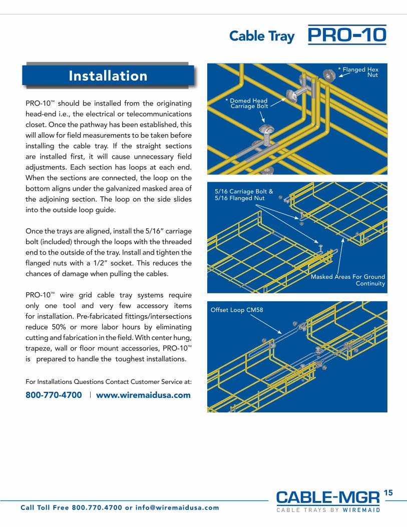
Cable Tray
PRO-10™ should be installed from the originating head-end i.e., the electrical or telecommunications closet. Once the pathway has been established, this will allow for field measurements to be taken before installing the cable tray. If the straight sections are installed first, it will cause unnecessary field adjustments. Each section has loops at each end. When the sections are connected, the loop on the bottom aligns under the galvanized masked area of the adjoining section. The loop on the side slides into the outside loop guide.
Once the trays are aligned, install the 5/16” carriage bolt (included) through the loops with the threaded end to the outside of the tray. Install and tighten the flanged nuts with a 1/2” socket. This reduces the chances of damage when pulling the cables.
PRO-10™ wire grid cable tray systems require only one tool and very few accessory items for installation. Pre-fabricated fittings/intersections reduce 50% or more labor hours by eliminating cutting and fabrication in the field. With center hung, trapeze, wall or floor mount accessories, PRO-10™ is prepared to handle the toughest installations.
For Installations Questions Contact Customer Service at:
800-770-4700 I www.wiremaidusa.com
Installation
* Domed Head Carriage Bolt
5/16 Carriage Bolt &5/16 Flanged Nut
Offset Loop CM58
Masked Areas For Ground Continuity
* Flanged Hex Nut
®
™

Wiremaid Products Division11711 W. Sample Rd • Coral Springs, FL 33065
Toll Free Phone: (800) 770-4700 | Toll Free Fax: (800) 548-5885Phone: (954) 545-9000 | Fax: (954) 545-9011
www.wiremaidusa.com • [email protected]
All rights reserved. All other trademarks and company names mentioned are the property of their respective owners.
C US
152012-2
®
™
Recommended


