1
2009 Maxima w/Navigation
Installation of KP Technologies Navigation Bypass Interface
The following installation procedure will aid you in installing the KP Technologies Navigation Bypass Interface Module into a 2009 Maxima with navigation. The creators of this document or KP Technologies are not responsible for any damages incurred to your vehicle or self as a result of installation of this module or the instructions set forth below. Improper installation may cause adverse effect and therefore please consult a professional prior to attempting this procedure.
Items / Tools Needed:
• KP Technologies Navigation Bypass Interface Module (Item NI#35) ‐ http://www.kptechnologies.com/products.php#/6
• Flat head screw driver or panel poppers
• Philips screw driver
• Pliers
• Wire strippers/crimpers
• Electrical tape
• Painters tape (optional)
• Wire connectors:
o Wire connection method is your choice. This tutorial will not explain how to tap/splice/solder wires.
o Option A: Crimp caps, crimp T connectors, butt connectors, etc.
o Option B: Solder, soldering iron/gun, etc.
o Zip ties, etc.
2
Steps
Disconnect the Battery......................................................................................................................... 3
Remove the Navigation Panel .............................................................................................................. 3
Remove the Radio Panel ...................................................................................................................... 5
Remove the Radio ................................................................................................................................ 7
Connect Wires ..................................................................................................................................... 9
Re‐Install ........................................................................................................................................... 17
Program the Module .......................................................................................................................... 17
3
Steps
1) DISCONNECT THE BATTERY FROM THE CAR. If you don’t, various electronic sensors (air bag, power windows, etc.) will trip.
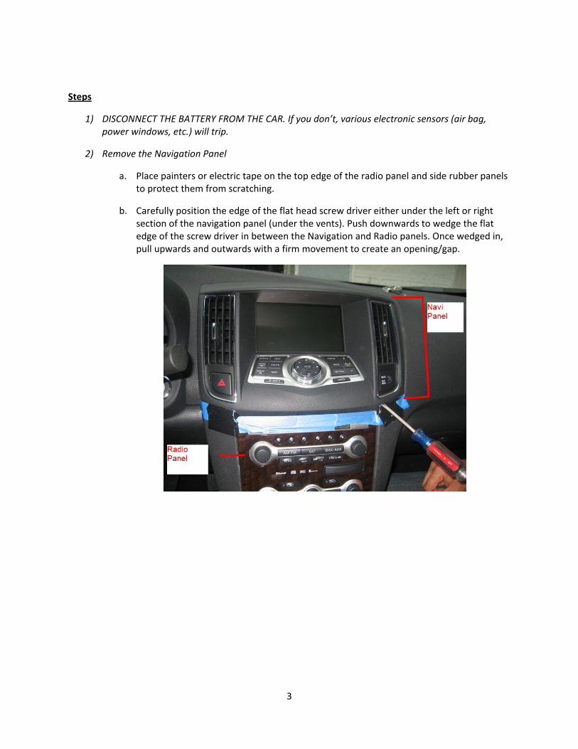
2) Remove the Navigation Panel
a. Place painters or electric tape on the top edge of the radio panel and side rubber panels to protect them from scratching.
b. Carefully position the edge of the flat head screw driver either under the left or right section of the navigation panel (under the vents). Push downwards to wedge the flat edge of the screw driver in between the Navigation and Radio panels. Once wedged in, pull upwards and outwards with a firm movement to create an opening/gap.

4
c. Slide your fingers in the small gap and pry the panel towards you and up in one firm
movement. Note: It will require some effort to pop the clips. You know you’ve dislodged the panel properly when you hear a loud pop.
d. Once you’ve lifted the panel off, disconnect the 3 connectors on the back of the panel and safely place the panel away. The following is a picture of the backside of the panel. Note: Removal of the actual navigation screen is unnecessary.
5
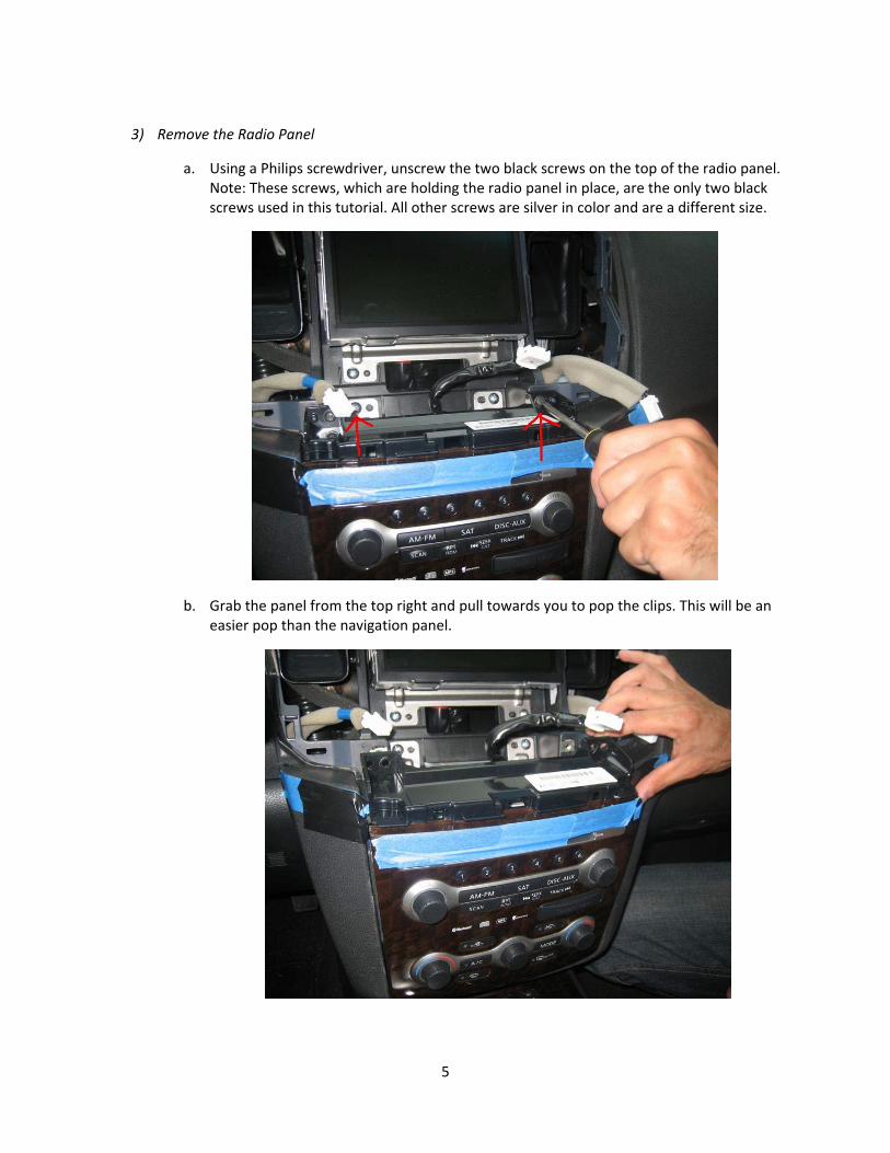
3) Remove the Radio Panel
a. Using a Philips screwdriver, unscrew the two black screws on the top of the radio panel. Note: These screws, which are holding the radio panel in place, are the only two black screws used in this tutorial. All other screws are silver in color and are a different size.
b. Grab the panel from the top right and pull towards you to pop the clips. This will be an easier pop than the navigation panel.
6
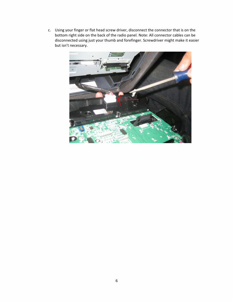
c. Using your finger or flat head screw driver, disconnect the connector that is on the bottom right side on the back of the radio panel. Note: All connector cables can be disconnected using just your thumb and forefinger. Screwdriver might make it easier but isn’t necessary.
7
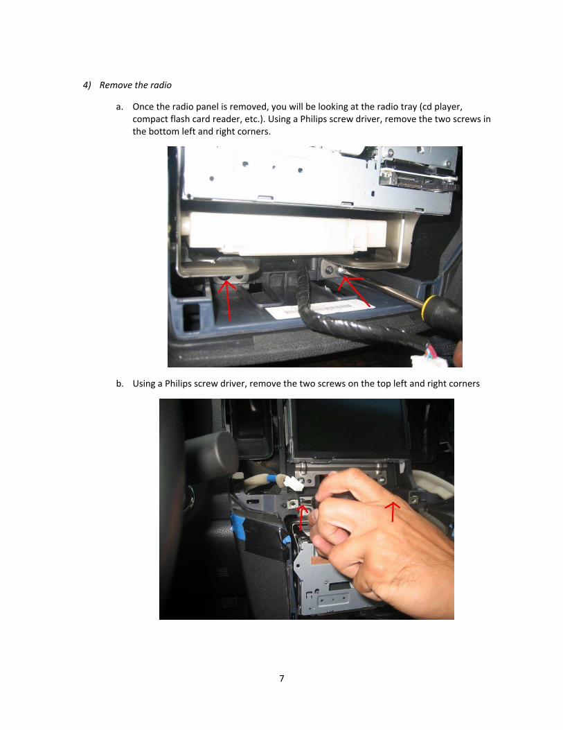
4) Remove the radio
a. Once the radio panel is removed, you will be looking at the radio tray (cd player, compact flash card reader, etc.). Using a Philips screw driver, remove the two screws in the bottom left and right corners.
b. Using a Philips screw driver, remove the two screws on the top left and right corners

8
c. Slide the radio tray out.
d. There are approximately 7 connectors on the back of the radio unit that need to be disconnected. Disconnect ALL connectors on the back of the unit. Safely place the radio tray away.
9
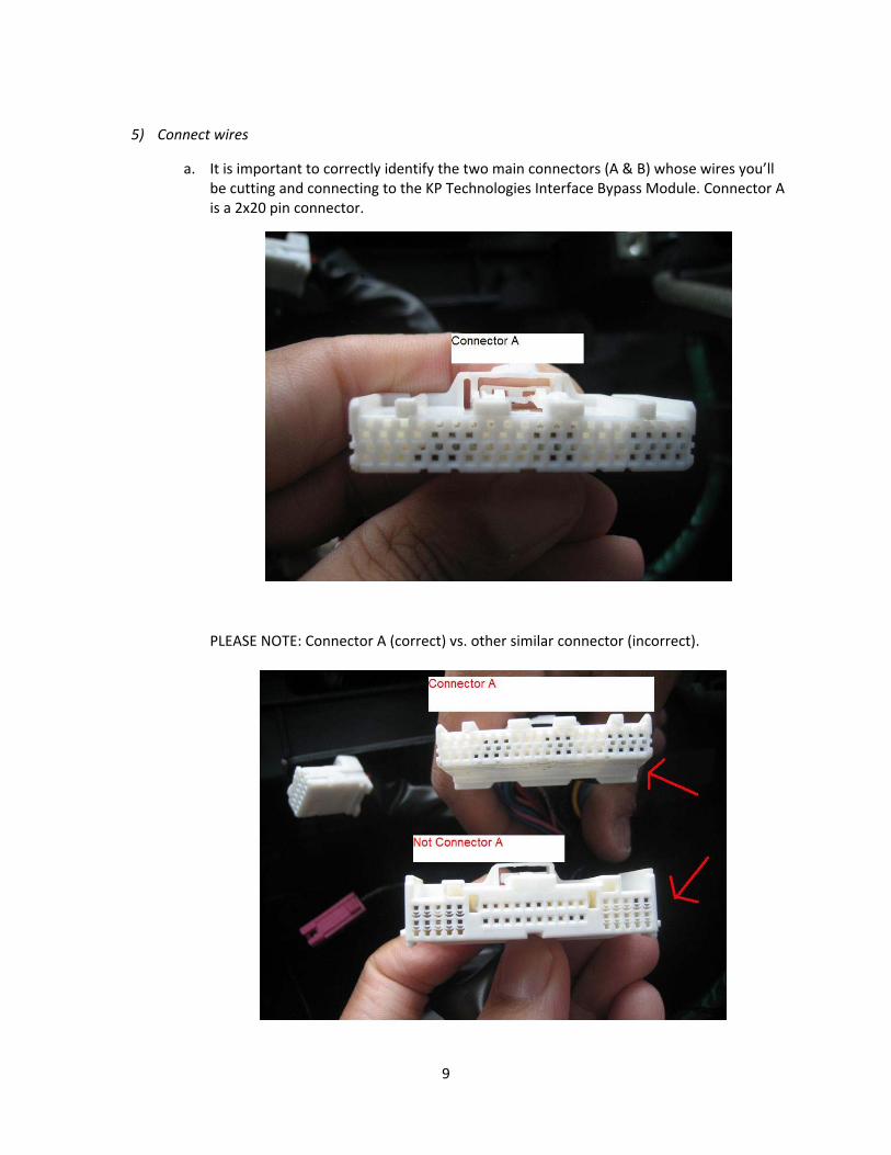
5) Connect wires
a. It is important to correctly identify the two main connectors (A & B) whose wires you’ll be cutting and connecting to the KP Technologies Interface Bypass Module. Connector A is a 2x20 pin connector.
PLEASE NOTE: Connector A (correct) vs. other similar connector (incorrect).
10
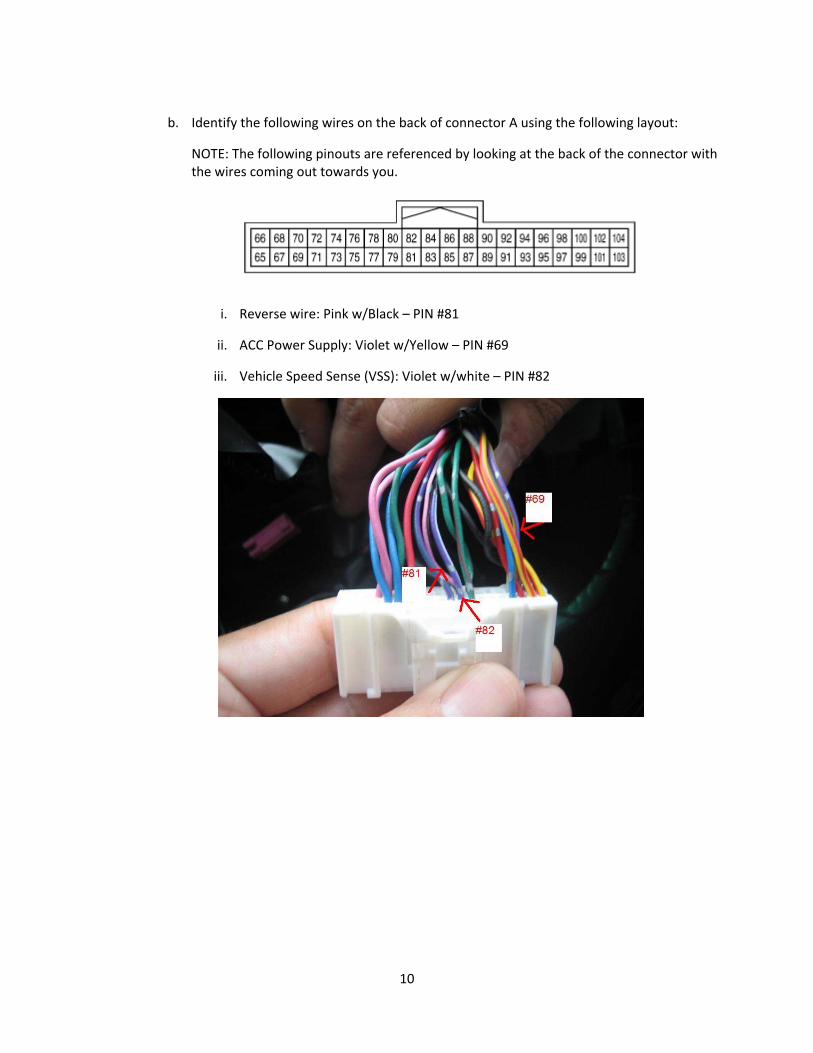
b. Identify the following wires on the back of connector A using the following layout:
NOTE: The following pinouts are referenced by looking at the back of the connector with the wires coming out towards you.
i. Reverse wire: Pink w/Black – PIN #81
ii. ACC Power Supply: Violet w/Yellow – PIN #69
iii. Vehicle Speed Sense (VSS): Violet w/white – PIN #82
11
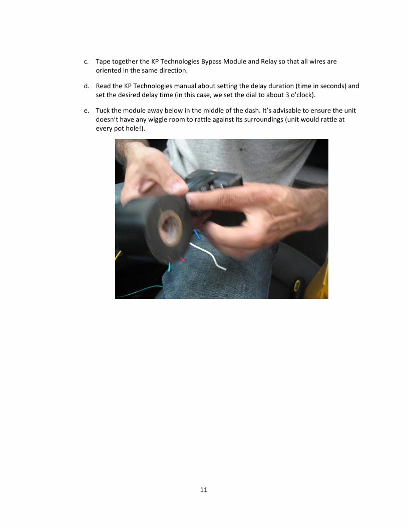
c. Tape together the KP Technologies Bypass Module and Relay so that all wires are
oriented in the same direction.
d. Read the KP Technologies manual about setting the delay duration (time in seconds) and set the desired delay time (in this case, we set the dial to about 3 o’clock).
e. Tuck the module away below in the middle of the dash. It’s advisable to ensure the unit doesn’t have any wiggle room to rattle against its surroundings (unit would rattle at every pot hole!).
12
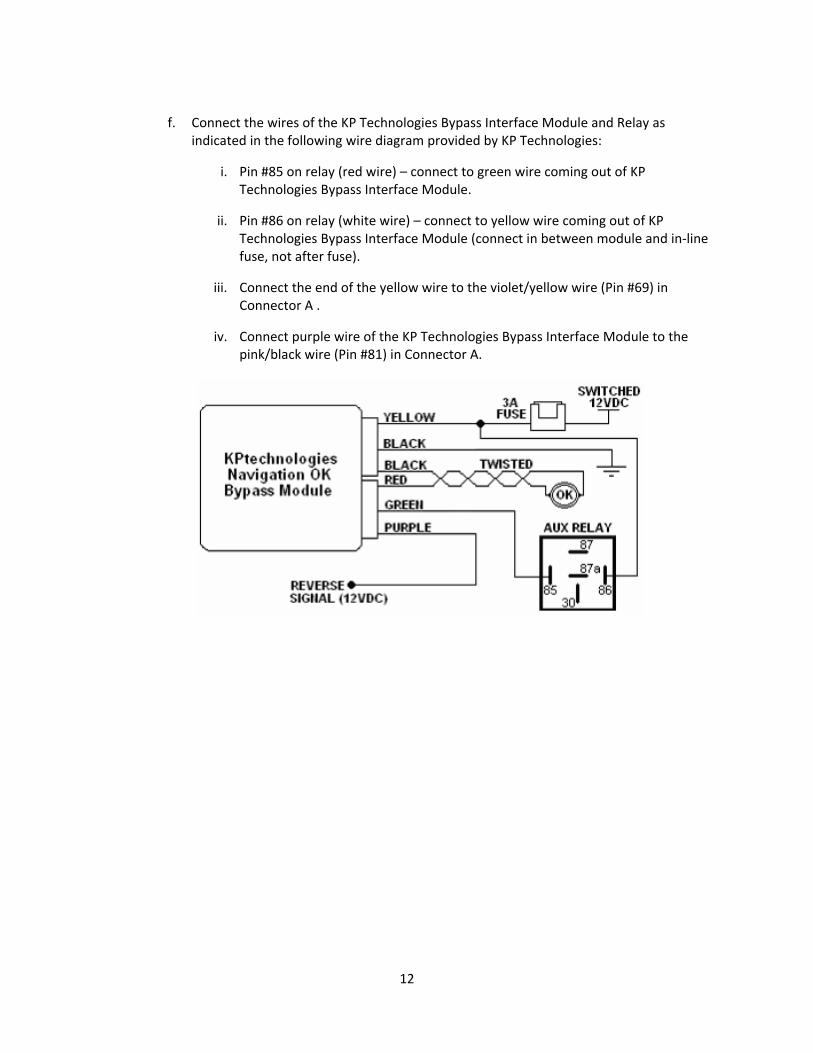
f. Connect the wires of the KP Technologies Bypass Interface Module and Relay as
indicated in the following wire diagram provided by KP Technologies:
i. Pin #85 on relay (red wire) – connect to green wire coming out of KP Technologies Bypass Interface Module.
ii. Pin #86 on relay (white wire) – connect to yellow wire coming out of KP Technologies Bypass Interface Module (connect in between module and in‐line fuse, not after fuse).
iii. Connect the end of the yellow wire to the violet/yellow wire (Pin #69) in Connector A .
iv. Connect purple wire of the KP Technologies Bypass Interface Module to the pink/black wire (Pin #81) in Connector A.
13
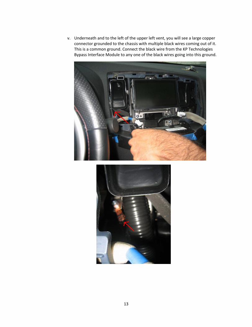
v. Underneath and to the left of the upper left vent, you will see a large copper
connector grounded to the chassis with multiple black wires coming out of it. This is a common ground. Connect the black wire from the KP Technologies Bypass Interface Module to any one of the black wires going into this ground.

14
vi. Cut the VSS wire (violet/white Pin #82) coming out of Connector A. Note: Ensure
you leave about 2 inches of wire from the connector as you will need to utilize both ends of the wire. Additional note: The VSS wire is the ONLY wire that gets cut. All other wires (ground, ACC, reverse, etc) get tapped/spliced.
vii. Connect the blue wire from the relay to one of the now‐cut ends of the VSS wire. Connect the black wire from the relay to the other end of the now‐cut VSS wire. Note: It does not matter which wire is connected to which end.
15
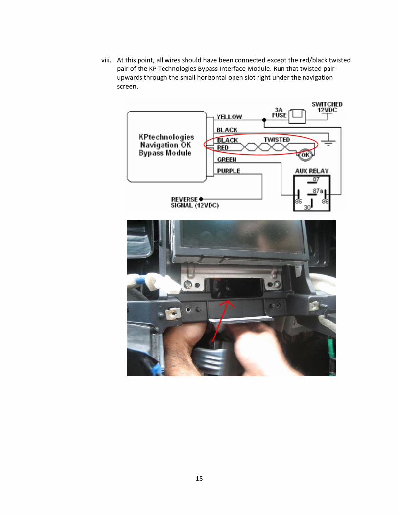
viii. At this point, all wires should have been connected except the red/black twisted
pair of the KP Technologies Bypass Interface Module. Run that twisted pair upwards through the small horizontal open slot right under the navigation screen.
16
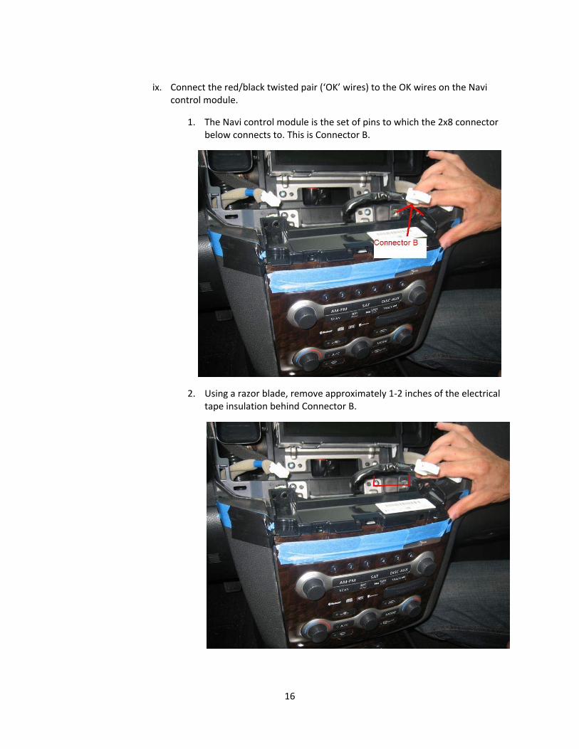
ix. Connect the red/black twisted pair (‘OK’ wires) to the OK wires on the Navi
control module.
1. The Navi control module is the set of pins to which the 2x8 connector below connects to. This is Connector B.
2. Using a razor blade, remove approximately 1‐2 inches of the electrical tape insulation behind Connector B.
17
3. Flip Connector B around so the wires are facing you and the clip is on
top. The two OK wires to tap are as follows:
a. Top row, 4th from the left: green w/orange
b. Bottom row, 3rd from the left: green
4. Connect the black wire of the twisted pair to either of the OK wires, and the red wire to the other OK wire. It does not matter which wire of the twisted pair connects to which of the OK wires.
6) Re‐Install
a. All wires have been connected. You are now done.
i. Reconnect all connectors to the back of the radio tray and re‐install the radio.
ii. Reconnect Connector B to the Radio Panel & install Radio Panel.
iii. Reconnect all three connectors of the Navi control module back to the Navigation panel.
7) Program the Module
a. Follow the directions on the KP manual to program the module to Mode 1.
i. In this mode, you have to hold the OK button for 2 seconds to activate the module. You know you’ve activated the module when you hear the relay make an audible click.
ii. Once activated, you can use the Bluetooth phone and/or enter an address in the navigation.
iii. Once you’re done entering the address or phone number, you now need to de‐activate the module. This is done by simply holding the OK button for two seconds. You will again hear the relay click. The module is now de‐activated.
iv. It is important to activate and de‐activate the module before and after using the phone or navigation because this will de‐activate and activate the Vehicle Speed Sensor. If you forget to de‐activate the module, the VSS will not be active and since the 2009 Navigation utilizes the VSS to determine the car’s position along the navigated path, the triangle that represents the car will never move along the path. It will only twist and turn (which reflects the activity of the GPS sensors) but never move along the yellow navigation line.
Recommended