1Denis Grondin / Julien Giraud – 01 December 2008
SLAB COOLING
Denis Grondin ([email protected]) Julien Giraud ([email protected])
•DEMONSTRATOR
2Denis Grondin / Julien Giraud – 01 Decembre 2008
SLAB COOLING - DEMONSTRATOR
Goal of experimental tests: a real thermal test to be compared to numerical
simulation, In order to answer to simplification of slab’s model, To know more precisely transfert coefficients,
To verify the behaviour of the cooling system. To reproduce as precisely as possible these tests
in simulations.

3Denis Grondin / Julien Giraud – 01 Decembre 2008
SLAB COOLING - DEMONSTRATOR
Finite element model
• Many configuration of heater ASU can be test.
• Shell model => the thikness of the copper plate can be changed.
• Convection can be adjusted between water and pipe (cold plate).
• Thermal foam between the copper plate and the cold plate is included in the model
• All the contact thermal résistances can be adjusted (cold plate / foam, foam / copper plate, copper plate / Resistance).
• Temperature is available at the center of each sensor (listing)
55401120.5
124.5
4Denis Grondin / Julien Giraud – 01 Decembre 2008
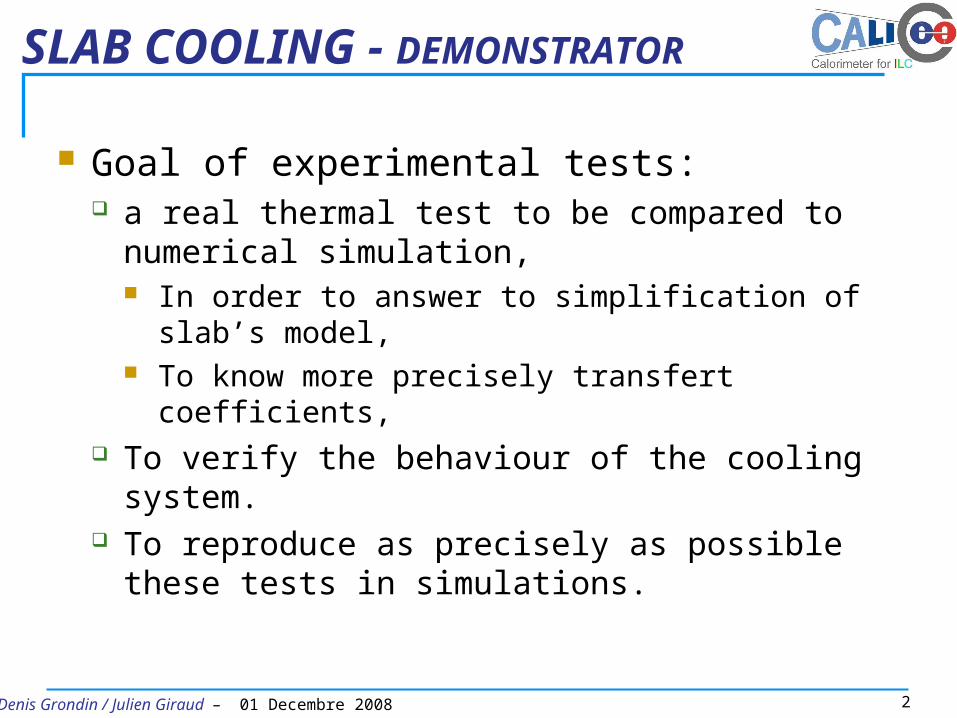
SLAB COOLING - DEMONSTRATOR Copper plate
Thermal foam
Cold plate
Heat surface and temperature point (FPGA location)
0.2 to 2W…

5Denis Grondin / Julien Giraud – 01 Decembre 2008
SLAB COOLING - DEMONSTRATORCold plate : 3 Solutions
-Assembled solution
-Water circulating into copper pipe (Internal diameter : 4 mm)
- Lot of welded pieces=> tricky assembly
Solution 1
6Denis Grondin / Julien Giraud – 01 Decembre 2008
SLAB COOLING - DEMONSTRATOR
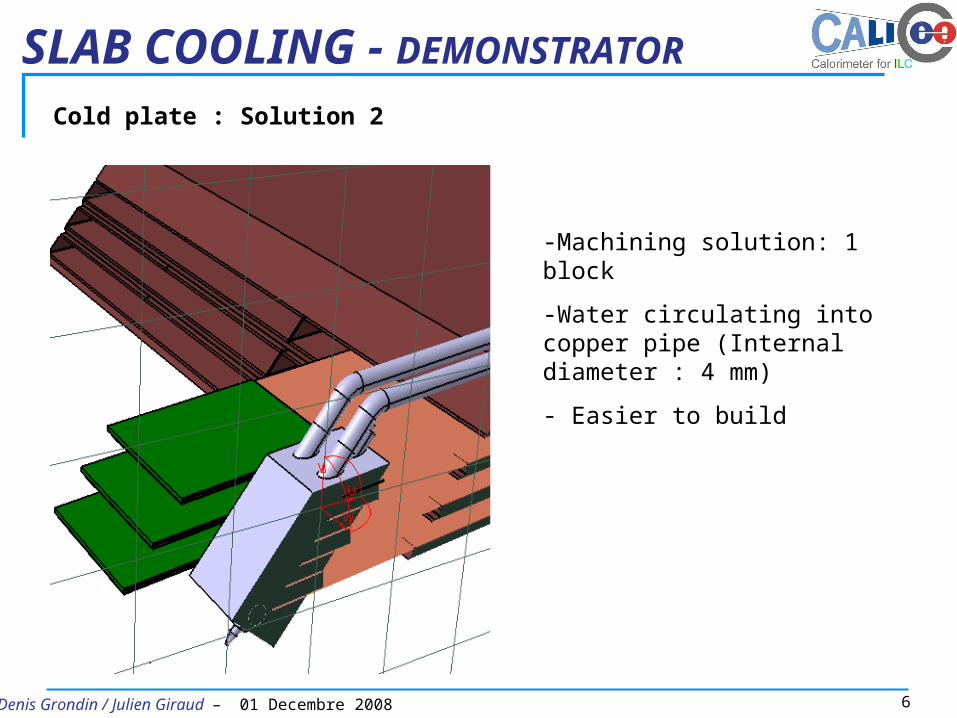
Cold plate : Solution 2
-Machining solution: 1 block
-Water circulating into copper pipe (Internal diameter : 4 mm)
- Easier to build

7Denis Grondin / Julien Giraud – 01 Decembre 2008
SLAB COOLING - DEMONSTRATOR
Cold plate : Solution 3
Water circuitHeatpipe
Main advantage :
Connection between Heat pipe and water circuit => contact, far from front-end.
Easy to assemble and reduce leak risk
~ Same geometry
Inside a heat pipe, at the hot interface a fluid turns to vapour and the gas naturally flows and condenses on the cold interface. The liquid falls or is moved by capillary action back to the hot interface to evaporate again and repeat the cycle.
8Denis Grondin / Julien Giraud – 01 Decembre 2008
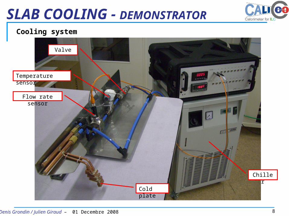
SLAB COOLING - DEMONSTRATORCooling system
Chiller
Temperature sensor
Flow rate sensor
Valve
Cold plate
9Denis Grondin / Julien Giraud – 01 Decembre 2008
SLAB COOLING - DEMONSTRATOR
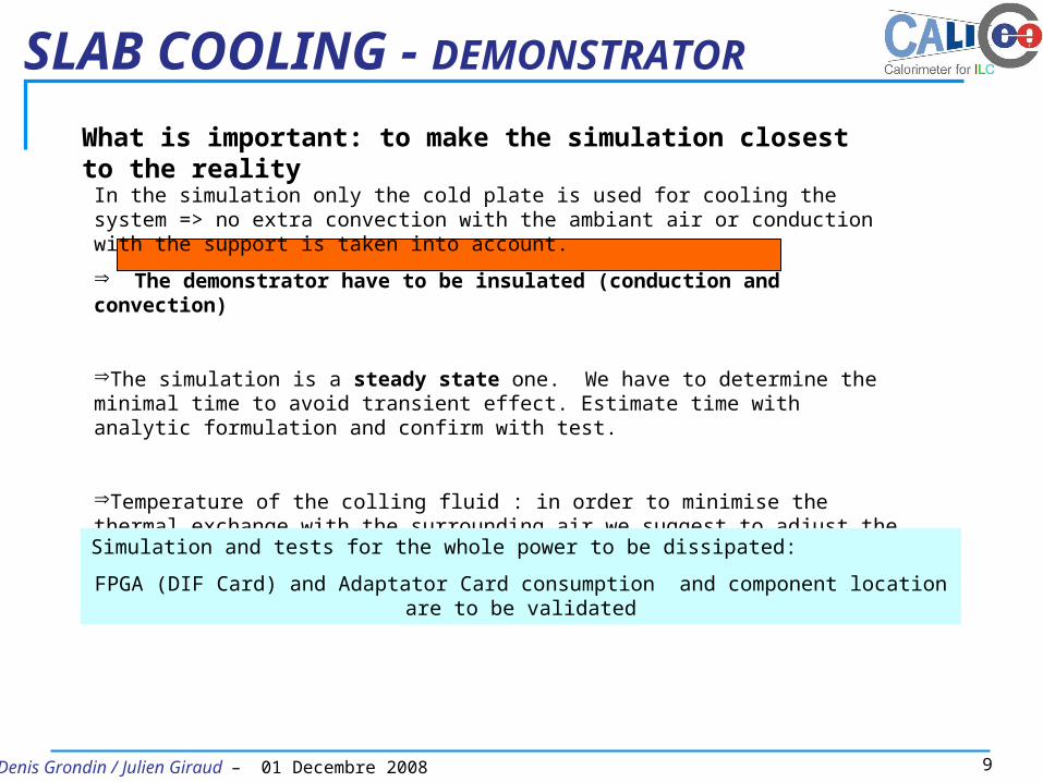
What is important: to make the simulation closest to the reality
In the simulation only the cold plate is used for cooling the system => no extra convection with the ambiant air or conduction with the support is taken into account.
The demonstrator have to be insulated (conduction and convection)
The simulation is a steady state one. We have to determine the minimal time to avoid transient effect. Estimate time with analytic formulation and confirm with test.
Temperature of the colling fluid : in order to minimise the thermal exchange with the surrounding air we suggest to adjust the cooling fluid temperature at the ambiant temperature room.
Simulation and tests for the whole power to be dissipated:
FPGA (DIF Card) and Adaptator Card consumption and component location are to be validated
Recommended