Embed Size (px)
DESCRIPTION
Miroc bts
Citation preview

ZXG10 S8001In-Door Pico Cell Base Transceiver Station
User Manual
Version 1.1
ZTE CORPORATION ZTE Plaza, Keji Road South, Hi-Tech Industrial Park, Nanshan District, Shenzhen, P. R. China 518057 Tel: (86) 755 26771900 800-9830-9830 Fax: (86) 755 26772236 URL: http://support.zte.com.cn E-mail: [email protected]

LEGAL INFORMATION Copyright © 2006 ZTE CORPORATION. The contents of this document are protected by copyright laws and international treaties. Any reproduction or distribution of this document or any portion of this document, in any form by any means, without the prior written consent of ZTE CORPORATION is prohibited. Additionally, the contents of this document are protected by contractual confidentiality obligations. All company, brand and product names are trade or service marks, or registered trade or service marks, of ZTE CORPORATION or of their respective owners. This document is provided “as is”, and all express, implied, or statutory warranties, representations or conditions are disclaimed, including without limitation any implied warranty of merchantability, fitness for a particular purpose, title or non-infringement. ZTE CORPORATION and its licensors shall not be liable for damages resulting from the use of or reliance on the information contained herein. ZTE CORPORATION or its licensors may have current or pending intellectual property rights or applications covering the subject matter of this document. Except as expressly provided in any written license between ZTE CORPORATION and its licensee, the user of this document shall not acquire any license to the subject matter herein. ZTE CORPORATION reserves the right to upgrade or make technical change to this product without further notice. Users may visit ZTE technical support website http://ensupport.zte.com.cn to inquire related information. The ultimate right to interpret this product resides in ZTE CORPORATION.
Revision History
Date Revision No. Serial No. Reason for Revision
Mar 10, 2008 R1.0 sjzl20080653 First edition

ZTE CORPORATION Values Your Comments & Suggestions! Your opinion is of great value and will help us improve the quality of our product documentation and offer better services to our customers.
Please fax to: (86) 755-26772236; or mail to Documentation R&D Department, ZTE CORPORATION, ZTE Plaza, A Wing, Keji Road South, Hi-Tech Industrial Park, Shenzhen, P. R. China 518057.
Thank you for your cooperation!
Document Name ZXG10 S8001(V1.1) In-Door Pico Cell Base Transceiver Station User Manual
Product Version V1.1 Document Revision Number R1.0
Serial No. sjzl20080653 Equipment Installation Date
Presentation: (Introductions, Procedures, Illustrations, Completeness, Level of Detail, Organization, Appearance)
Good Fair Average Poor Bad N/A
Accessibility: (Contents, Index, Headings, Numbering, Glossary)
Good Fair Average Poor Bad N/A
Your evaluation of this documentation
Intelligibility: (Language, Vocabulary, Readability & Clarity, Technical Accuracy, Content)
Good Fair Average Poor Bad N/A
Your suggestions for improvement of this documentation
Please check the suggestions which you feel can improve this documentation: Improve the overview/introduction Make it more concise/brief
Improve the Contents Add more step-by-step procedures/tutorials
Improve the organization Add more troubleshooting information
Include more figures Make it less technical
Add more examples Add more/better quick reference aids
Add more detail Improve the index
Other suggestions
__________________________________________________________________________
__________________________________________________________________________
__________________________________________________________________________
__________________________________________________________________________
__________________________________________________________________________
# Please feel free to write any comments on an attached sheet.
If you wish to be contacted regarding your comments, please complete the following:
Name Company
Postcode Address
Telephone E-mail

This page is intentionally blank.
Contents
About this Manual............................................................. i
Purpose................................................................................ i Intended Audience ................................................................. i Prerequisite Skill and Knowledge .............................................. i What is in This Manual............................................................ i Conventions......................................................................... ii How to Get in Touch............................................................. iii
Declaration of RoHS Compliance..................................... v
Chapter 1.......................................................................... 1
Introduction..................................................................... 1
Overview .............................................................................1 Appearance..........................................................................1 Specifications .......................................................................2 System Architecture ..............................................................3 Key Features........................................................................7 ZXG10 8000 Family............................................................. 11
Chapter 2........................................................................13
Subsystems and External Interfaces ............................13
Hardware Subsystems ......................................................... 13 External Interfaces.............................................................. 16
Chapter 3........................................................................19
Installation.....................................................................19
Mounting Instructions.......................................................... 19 Antenna and Cable ports...................................................... 21
Chapter 4........................................................................23
Troubleshooting.............................................................23
Checking the Front Panel Indicators....................................... 23
Classification of Alarms ........................................................24 iBSC Access Failure .............................................................25 Control Plane Link Broken.....................................................25 Link Establishment Failure on Service Plane ............................26 DSP Initialization Failure.......................................................26 Flash Memory Failure...........................................................27 Watchdog of DSP Overflows..................................................27 Frequency Not Available Alarm..............................................28 Local Oscillator of Transmission Channel Losing Lock Alarm.......28 Link Parameter Configuration Failure......................................28 AD Unavailability Alarm........................................................29
Chapter 5........................................................................31
Solutions ........................................................................31
Networking Solutions..................................................... 31 Existing Transmission Resource .............................................31 Internet Resource ...............................................................32 Operator’s Data Network ......................................................32
Application Solutions ..................................................... 32 Family Application Solution ...................................................34 Indoor Coverage Solution .....................................................34 Hot Spot Coverage Solution ..................................................35 Blind Area Solution ..............................................................37 Enterprise Application Solution ..............................................37 Special Applications Solution.................................................38
Appendix A.....................................................................39
Abbreviations.................................................................39
Appendix B .....................................................................41
Figures............................................................................41
Tables .............................................................................43
Index..............................................................................45

Confidential and Proprietary Information of ZTE CORPORATION i
About this Manual
ZXG10 S8001 (V1.1) Indoor Pico Cell Base Transceiver Station is also termed as HBTS, Home BTS, ZXG10 S8001, and sometimes as Pico BTS in this manual.
Purpose
This manual describes the features and operation of ZXG10 S8001 (V1.1) Indoor Pico Cell Base Transceiver Station.
Intended Audience
This document is intended for the users of ZXG10 S8001 (V1.1) Indoor Pico Cell Base Transceiver Station.
Prerequisite Skill and Knowledge
To use this document effectively, users should have a general understanding of wireless telecommunications technology. Familiarity with the following is helpful:
The ZXG10 8000 Family
Basic GSM technology with GPRS and EDGE
What is in This Manual
This Manual contains the following sections:
T AB L E 1 M AN U AL S U M M AR Y
Section Summary
Chapter 1, Introduction Gives an overview, architecture, and features of the HBTS.
Chapter 2, Subsystems and External Interfaces
Describes about hardware subsystems and External interfaces

ZXG10 S8001 (V1.1) In-Door Pico Cell Base Transceiver Station User Manual
ii Confidential and Proprietary Information of ZTE CORPORATION
Section Summary
Chapter 3, Installation Describes two installation modes supported by S8001
Chapter 4, Troubleshooting
Classifies alarms and describes symptoms, fault causes, and troubleshooting methods for different kinds of possible faults
Chapter 5, Solutions Explains the networking and application solutions provided by S8001
Appendix A, Abbreviations
List of all abbreviations used in the manual
Appendix B, Figures and Tables
List of all figures and tables used in the manual
Index Index of terms and definitions used in this manual
Conventions
ZTE documents employ the following typographical conventions.
T AB L E 2 TY P O G R AP H I C AL C O N V E N T I O N S
Typeface Meaning
Italics References to other Manuals and documents.
“Quotes” Links on screens.
Bold Menus, menu options, function names, input fields, radio button names, check boxes, drop-down lists, dialog box names, window names.
CAPS Keys on the keyboard and buttons on screens and company name.
Constant width Text that you type, program code, files and directory names, and function names.
[ ] Optional parameters.
{ } Mandatory parameters.
| Select one of the parameters that are delimited by it.
Note: Provides additional information about a certain topic.
Checkpoint: Indicates that a particular step needs to be checked before proceeding further.
Tip: Indicates a suggestion or hint to make things easier or more productive for the reader.
Typographical Conventions
About this Manual
Confidential and Proprietary Information of ZTE CORPORATION iii
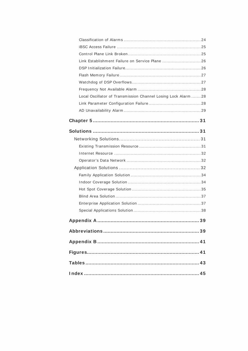
T AB L E 3 M O U S E OP E R AT I O N C O N V E N T I O N S
Typeface Meaning
Click Refers to clicking the primary mouse button (usually the left mouse button) once.
Double-click Refers to quickly clicking the primary mouse button (usually the left mouse button) twice.
Right-click Refers to clicking the secondary mouse button (usually the right mouse button) once.
Drag Refers to pressing and holding a mouse button and moving the mouse.
How to Get in Touch
The following sections provide information on how to obtain support for the documentation and the software.
If you have problems, questions, comments, or suggestions regarding your product, contact us by e-mail at [email protected]. You can also call our customer support center at (86) 755 26771900 and (86) 800-9830-9830.
ZTE welcomes your comments and suggestions on the quality and usefulness of this document. For further questions, comments, or suggestions on the documentation, you can contact us by e-mail at [email protected]; or you can fax your comments and suggestions to (86) 755 26772236. You can also browse our website at http://support.zte.com.cn, which contains various interesting subjects like documentation, knowledge base, forum and service request.
Mouse Operation
Conventions
Customer Support
Documentation Support
ZXG10 S8001 (V1.1) In-Door Pico Cell Base Transceiver Station User Manual
iv Confidential and Proprietary Information of ZTE CORPORATION
This page is intentionally blank.
Confidential and Proprietary Information of ZTE CORPORATION v
Declaration of RoHS Compliance
To minimize the environmental impact and take more responsibility to the earth we live, this document shall serve as formal declaration that the ZXG10 S8001 (V1.1) In-Door Pico Cell Base Transceiver Station manufactured by ZTE CORPORATION is in compliance with the Directive 2002/95/EC of the European Parliament - RoHS (Restriction of Hazardous Substances) with respect to the following substances:
Lead (Pb)
Mercury (Hg)
Cadmium (Cd)
Hexavalent Chromium (Cr (VI))
PolyBrominated Biphenyls (PBB’s)
PolyBrominated Diphenyl Ethers (PBDE’s)
The usage of the above substances in ZXG10 S8001 is explained in Table 4.
T AB L E 4 – U S AG E E X P L A N A T I O N O F T H E H AZ AR D O U S S U B S T AN C E S I N S8001
Hazardous substances
Names of Parts
Pb
Hg Cd Cr(VI) PBB’s PBDE’s
System
0 0 0 0 0 0
Cables and Assembly
0 0 0 0 0 0
Auxiliary Equipment
0 0 0 0 0 0
Table Explanation:
0: The usage of the substance in all of the components is less than the allowed values given by 2002/95/EC standard.
ZXG10 S8001 (V1.1) In-Door Pico Cell Base Transceiver Station User Manual
vi Confidential and Proprietary Information of ZTE CORPORATION
×: The usage of the substance in at least one of the components is beyond the allowed values given by 2002/95/EC standard.
The ZXG10 S8001 (V1.1) In-Door Pico Cell Base Transceiver Station manufactured by ZTE CORPORATION meet the requirements of EU 2002/95/EC; however, some assemblies are customized to client specifications. Addition of specialized, customer-specified materials or processes which do not meet the requirements of EU 2002/95/EC may negate RoHS compliance of the assembly. To guarantee compliance of the assembly, the need for compliant product must be communicated to ZTE CORPORATION in written form.
This declaration is issued based on our current level of knowledge. Since conditions of use are outside our control, ZTE CORPORATION makes no warranties, express or implied, and assumes no liability in connection with the use of this information.
Confidential and Proprietary Information of ZTE CORPORATION 1
C h a p t e r 1
Introduction
This chapter introduces the basic features of ZXG10 S8001.
Overview
ZXG10 S8001 is single-carrier indoor BTS, with low power and small capacity. It is a Pico BTS based on IP architecture. Its deployment areas include public areas such as airports, schools, departmental stores, and offices. Usually, ZXG10 S8001 adopts wall-mounted installation mode. It can also be installed on a desk.
The external dimensions of ZXG10 S8001 are 265 mm × 200 mm × 58 mm (L × W × H).
The integrated equipment body is formed by the plastic sheet of Acrylonitrile Butadiene Styrene (ABS) and the weight is less than 2 kg.
Note: ZXG10 S8001 (V1.1) Indoor Pico Cell Base Transceiver Station is also termed as HBTS, Home BTS, ZXG10 S8001, and sometimes as Pico BTS in this manual
Appearance
The appearance of S8001 is as follows:
Two antennas Four LED indicators:
Power supply indicator (PWR, green)
Running indicator (RUN, green)
Network interface indicator (LINK, green)

ZXG10 S8001 (V1.1) In-Door Pico Cell Base Transceiver Station User Manual
2 Confidential and Proprietary Information of ZTE CORPORATION
Alarm indicator (ALARM, red)
Network port -48 V power supply port
ZXG10 S8001 has three parts:
Structural enclosure
PCB functional board
Antennas
F I G U R E 1 – AP P E A R A N C E O F HBTS
Specifications
Table 5 shows the environmental specifications for HBTS.
T AB L E 5 - E N V I R O N M E N T AL C O N D I T I O N S
Environment Type Description
Receiving sensitivity -100 dBm
Maximum transmission power 8PSK: 16 dBm
GMSK: 18 dBm
Output power of power amplifier 30 mW ~ 200 mW (can be adjusted according to user requirement)
Peak power consumption 13 W
Lower limit of temperature
-5 ℃ Weather environment conditions
Upper limit of temperature
45 ℃

Chapter 1 - Introduction
Confidential and Proprietary Information of ZTE CORPORATION 3
Environment Type Description
Lower limit of relative humidity
20%
Upper limit of relative humidity
80%
There are two power supply modes: PoE and local power supply.
The equipment adopts Ethernet cable for power supply, and works normally within the voltage fluctuation range. The function is called Power over Ethernet (PoE).
For local power supply, the voltage fluctuation range is 90 V AC ~ 260 V AC. A power adapter with built-in battery is adopted to connect with AC power. If the equipment does not connect with an external power supply, the built-in battery can provide power supply for the HBTS for 30 minutes.
For full configuration, MTBF of the integrated equipment is not less than 100000 hours.
System Architecture
ZXG10 S8001 performs data conversion and data processing between Um interface and IP Abis interface.
The S8001 system consists of the following seven subsystems:
Home-BTS Baseband Control & Processing Unit (HBCU)
Home-BTS Transceiver Unit (HTRU)
Home-BTS Interface Board (HIB)
Home-BTS Antenna Equipment Module (HAEM)
WiFi Subsystem
Home-BTS Carrier Management System (hCMS)
Home-BTS Channel Processor (hCHP)
The hCMS runs on the CPU of HBCU while the hCHP runs on the DSP of HBCU. For further details, see Software Architecture.
The hardware subsystem mainly consists of:
Baseband board
RF board
Interface board
Power supply
Mean Time between
Failures (MTBF)

ZXG10 S8001 (V1.1) In-Door Pico Cell Base Transceiver Station User Manual
4 Confidential and Proprietary Information of ZTE CORPORATION
Antenna feeder part
WiFi
The hardware subsystem serves for the inter-conversion between air signal and digital signal. Base station cost and hardware structural integrity is considered in the design.
Figure 2 shows the system architecture of ZXG10 S8001.
F I G U R E 2 - S Y S T E M AR C H I T E C T U R E
Note: The MMI network interface and the IP Abis interface are the same interface.
Table 6 describes ZXG10 S8001 subsystems.
T AB L E 6 - ZXG10 S8001 SU B S Y S T E M S
Subsystem ID
Subsystem Name
Subsystem Type
Subsystem Functions
hCMS Home-BTS Carrier Management Software Subsystem
Software subsystem
Makes conversion from air interface to IP Abis interface; Performs base station control and signaling process
hCHP Home-BTS Channel Processor Software Subsystem
Software subsystem
Processes layer-1 protocol of air interface protocols; Does GMSK and 8PSK demodulation
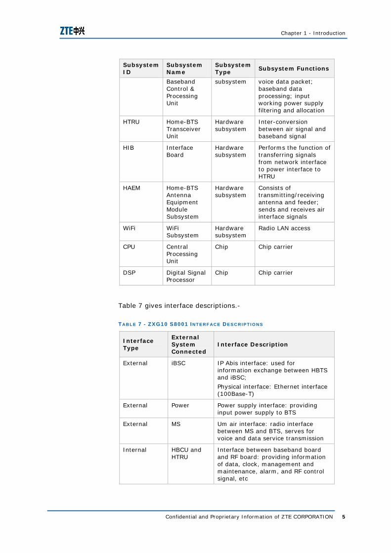
HBCU Home-BTS Hardware Converts IP packet into
Chapter 1 - Introduction
Confidential and Proprietary Information of ZTE CORPORATION 5
Subsystem ID
Subsystem Name
Subsystem Type
Subsystem Functions
Baseband Control & Processing Unit
subsystem voice data packet; baseband data processing; input working power supply filtering and allocation
HTRU Home-BTS Transceiver Unit
Hardware subsystem
Inter-conversion between air signal and baseband signal
HIB Interface Board
Hardware subsystem
Performs the function of transferring signals from network interface to power interface to HTRU
HAEM Home-BTS Antenna Equipment Module Subsystem
Hardware subsystem
Consists of transmitting/receiving antenna and feeder; sends and receives air interface signals
WiFi WiFi Subsystem
Hardware subsystem
Radio LAN access
CPU Central Processing Unit
Chip Chip carrier
DSP Digital Signal Processor
Chip Chip carrier
Table 7 gives interface descriptions.-
T AB L E 7 - ZXG10 S8001 I N T E R F AC E D E S C R I P T I O N S
Interface Type
External System Connected
Interface Description
External iBSC IP Abis interface: used for information exchange between HBTS and iBSC;
Physical interface: Ethernet interface (100Base-T)
External Power Power supply interface: providing input power supply to BTS
External MS Um air interface: radio interface between MS and BTS, serves for voice and data service transmission
Internal HBCU and HTRU
Interface between baseband board and RF board: providing information of data, clock, management and maintenance, alarm, and RF control signal, etc

ZXG10 S8001 (V1.1) In-Door Pico Cell Base Transceiver Station User Manual
6 Confidential and Proprietary Information of ZTE CORPORATION
Interface Type
External System Connected
Interface Description
Internal HBCU and WiFi module
Interface between baseband board and WiFi module: used for information exchange between CPU and WiFi module;
Physical interface: PCI interface
Internal HTRU and antenna feeder
Interface between antenna feeder and RF board
Hardware Architecture
ZXG10 S8001 hardware mainly consists of:
Baseband board HBCU
RF board HTRU
Interface board HIB
Antenna feeder equipment module HAEM
Wireless network card WiFi
Baseband board (HBCU) mainly performs:
Baseband data processing
System control
Radio channel control and processing
Radio channel data sending and receiving
Baseband signal demodulation from radio carriers
RF board (HTRU) mainly provides GSM system baseband signal modulation on radio carriers, radio carrier sending and receiving, and air signal combining and dividing. HTRU also performs the PoE function, extracting the power supply from Ethernet cable.
HIB provides the network interface socket and power interface to connect the HBTS with external equipments. It also provides the power socket for power supply with built-in battery. With these interfaces, it transfers signals from network interface to power interface to HTRU.
HAEM includes feeder and antenna. It mainly sends and receives air interface radio signals.
HBCU Function
HTRU Function
HIB Function
HAEM Function

Chapter 1 - Introduction
Confidential and Proprietary Information of ZTE CORPORATION 7
WiFi is an outsourced module. It includes wireless network card and wireless network card antenna. WiFi connects with PCI interface of HBCU board through PCI connector and serves for the WiFi function.
Software Architecture
ZXG10 S8001 software system follows the divided processing method of BTS software:
hCMS runs on the CPU of HBCU, performing conversion from layer-2 and layer-3 protocols of Um interface to network interface protocols.
HCHP runs on the DSP of HBCU, performing functions with high real-time requirements, assembling/disassembling frames, dynamic frequency point scanning algorithm, and Um interface layer-1 protocol processing.
Key Features
GSM/GPRS/EDGE, FR, EFR, HR, AMR
Considering working environment and performance/price ratio optimization, at most 7 TCH service channels are supported for GSM/GPRS and 2 ~ 4 PDTCH service timeslots are supported for EDGE.
100Base-T Ethernet network interface and IP Abis interface
Supports 100Base-T Ethernet network interface and IP Abis interface, accesses public or private IP networks, and establishes links with iBSC and other network equipments. ZXG10 S8001 accesses IP network through xDSL, FTT, LAN, etc.
WiFi function,
ZXG10 S8001 supports IEEE 802.11g:2400 MHz ~ 2483.5 MHz and OFDM modulation/CCK modulation. The data rate is as high as 54 Mbps, 50% more than 802.11a in distance. It follows the globally unified frequency band standard, ultimately compatible with 802.11b.
WiFi Function
hCMS Function
hCHP Function
ZXG10 S8001 (V1.1) In-Door Pico Cell Base Transceiver Station User Manual
8 Confidential and Proprietary Information of ZTE CORPORATION
In addition to supporting GSM base station functions, HBTS also supports WiFi functions. Thus users can enjoy both GSM services and high-speed data services.
Intelligent frequency search and frequency point setting
ZXG10 S8001 automatically searches frequency points within the specified resource range and reports searched signal information to iBSC.
Carrier frequency point setting of the base station is determined by iBSC.
Since HBTS has small coverage range, it is both time consuming and arduous to plan frequency points by the traditional macro base station network planning and optimization method. Thus HBTS provides the intelligent frequency search and frequency point setting functions, providing convenience for users to the maximum extent.
Frequency deviation correction
ZXG10 S8001 can search for a nearby base station with the best signal quality, of which the FCCH is taken as reference. According to the reference, S8001 calculates the carrier frequency deviation between the current base station and the reference base station, and calculates the clock bias. Then, S8001 makes compensation to correct the frequency deviation.
PoE and local power supply, supports instant switching between PoE and local power supply
ZXG10 S8001 adopts DC -48 V for remote power supply, which is a safety power supply. The base station starts working once the network cable is connected. Installation is simple and convenient. IEEE802.3af PD controller is adopted, which can be connected with any hub satisfying IEEE802.3af PSE. The base station can be installed anywhere if the network cable is present. Considering that the old hub can not provide power supply, remote power supply equipments are added between hubs and base station.
The power supply mode is very flexible. Local power supply and remote power supply are combined and interfaces of the two modes are provided, satisfying requirements of various customers. It also supports automatic protection for over-voltage, under-voltage and over-current.
For PoE power supply, the maximum power consumption is 13 W. For local power supply, the power supply adapter is connected to 90 V AC ~ 260 V AC. The built-in battery in power supply adapter

Chapter 1 - Introduction
Confidential and Proprietary Information of ZTE CORPORATION 9
provides power supply for HBTS to work with full load up to 30 minutes in case of power failure.
All four frequency bands of GSM
HBTS supports the four frequency bands of GSM: 850 MHz/900 MHz/1800 MHz/1900 MHz. Priority is given to 900/1800 MHz.
Lightning Protection Level
The lightning protection level is C.
The external protection level (standard) is IP30.
Restart duration (due to power-off)
The duration of restart due to power-off is 60 s ~ 90 s.
BTS Synchronization Mode and Precision Requirement
HBTS supports both internal synchronization and external synchronization. The precision requirement is 0.1 PPM.
Maximum transmission power: 8PSK: 16 dBm; GMSK: 18 dBm
HBTS is used to solve indoor coverage problems for enterprise and home users, solving two kinds of problems:
1. Poor indoor coverage;
2. Network capacity is not enough (for enterprise and office applications) though indoor coverage is good.
Such purposes determine HBTS only covers shorter distance, for example, within 50 m. Thus the transmission power is restricted and is 16 dBm for 8PSK and 18 dBm for GSMK, satisfying the Pico-BTS transmission power requirement in GSM 05 05 of 3GPP specification. The maximum transmission power is according to the safe value approved by the industry for indoor solution.
Abis over IP
HBTS connects with iBSC through Abis interface and adopts IP bearer (Abis Over IP).
ZXG10 S8001 (V1.1) In-Door Pico Cell Base Transceiver Station User Manual
10 Confidential and Proprietary Information of ZTE CORPORATION
In downlink direction, HBTS receives the control signal sent by iBSC through network interface, and subsequently controls and manages HBTS radio channels. Meanwhile, HBTS sends the service data received from iBSC to radio terminal users.
In uplink direction, HBTS reports radio terminal user information to iBSC and sends radio terminal user data to iBSC after processing. In addition, HBTS also reports O&M information to network side through this interface, facilitating GSM O&M center for HBTS management and maintenance.
Radio Channel Management
In GSM system, radio channels are divided into two categories called logical channels and physical channels. ZXG10 S8001 performs mapping between logical channels and physical channels and controls and manages these channels.
Based on the channel configuration information sent by iBSC, ZXG10 S8001 performs the following functions for information transmitted on various channels:
Coding
Decoding
Digital modulating (GMSK or 8PSK)
Digital demodulating
Interleaving
De-interleaving
Encryption
Decryption
ZXG10 S8001 provides random access attempt test for radio terminal users and reports the information to iBSC to request assignment command, thus to complete a call.
ZXG10 S8001 performs uplink radio link measurement, sends the downlink radio link quality reported by radio terminal users to iBSC. It also performs preprocessing of received information.
ZXG10 S8001 reports the interference level and congestion on channels to iBSC. iBSC then judges and allocates channels, which improves the channel usage ratio.
ZXG10 S8001 sends the paging commands according to correct paging group requirements. These paging commands are sent from MSC and initiated by iBSC.
Downlink Direction
Uplink Direction
Channel Processing
Random Access
Measurement
Radio Resource
Indication
Paging

Chapter 1 - Introduction
Confidential and Proprietary Information of ZTE CORPORATION 11
Um Interface and Radio Carrier Functions
ZXG10 S8001 modulates the GMSK/8PSK-modulated baseband signals on the carrier frequencies to be sent and transmits them into air after power amplification.
For Um interface, the site frequency error does not exceed ±0.1 PPM.
For GMSK modulation, Root Mean Square (RMS) of phase error does not exceed 5° and the peak value does not exceed 20°. For 8PSK modulation, RMS of EVM does not exceed 7% and the peak value does not exceed 22%.
ZXG10 S8001 demodulates the modulated carrier signal sent from radio terminal users and restores it to the baseband signal.
ZXG10 S8001 adjusts the transmission power according to measurement report and downlink power level reported by radio terminal users. This reduces the influence on radio channels of other users.
GSM/GPRS/EDGE/FR/EFR/HR/AMR Support
Considering working environment and performance/price ratio optimization, at most 7 TCH service channels are supported for GSM/GPRS and 2 ~ 4 PDTCH service timeslots are supported for EDGE.
In addition, it also supports Full Rate (FR), Enhanced Full Rate (EFR), Half Rate (HR), and Adaptive Multi Rate (AMR).
Indicators
There are four LED indicators on the front panel:
Power supply indicator (PWR, green)
Running indicator (RUN, green)
Alarm indicator (ALARM, red)
Network interface indicator (LINK, green)
ZXG10 8000 Family
The ZXG10 8000 family includes:
ZXG10 M8206 indoor/outdoor compact BTS
ZXG10 M8202 indoor/outdoor compact BTS
Modulation and
Transmission
Reception and Demodulation
Power Control

ZXG10 S8001 (V1.1) In-Door Pico Cell Base Transceiver Station User Manual
12 Confidential and Proprietary Information of ZTE CORPORATION
ZXG10 B8112 outdoor macro BTS
ZXG10 R8102 used in conjunction with ZXG10 B8048 multi-mode BBU
ZXG10 S8001 multi-mode Pico BTS EDGE + WiFi
ZXG10 B8018 indoor macro BTS
F I G U R E 3 - ZXG10 8000 F AM I L Y

Confidential and Proprietary Information of ZTE CORPORATION 13
C h a p t e r 2
Subsystems and External Interfaces
This chapter describes the hardware subsystems and interfaces of ZXG10 S8001.
Hardware Subsystems
Baseband Subsystem (HBCU)
HBCU is the board for control, operation, maintenance, and baseband processing. According to functions, S8001 is divided into the following units:
Power supply processing
Interface protection
Network interface
Baseband processing
RF processing
Antenna feeder
HBCU board performs the functions of power supply processing, network interface, and baseband processing.
Following are the detailed HBCU board functions:
Provides a 10/100 Mbps Ethernet interface for Abis interface transmission
Implements mapping from IP data packet to timeslot
Monitors, controls, and maintains the whole base station system
Manages all board programs and Field Programmable Gate Array (FPGA) configuration file versions, supports near-end

ZXG10 S8001 (V1.1) In-Door Pico Cell Base Transceiver Station User Manual
14 Confidential and Proprietary Information of ZTE CORPORATION
and far-end version upgrades, and supports version upgrade for programmable devices
Supports channel coding/decoding; supports CS service (HR/FR/EFR/AMR) and PS service (CS1-4/MCS1-9)
Uplink/downlink protocol processing
HPI interface message processing
Implements radio channel control and processing for single carrier
Implements demodulation for digital baseband single carrier IQ signal, supports GMSK and 8PSK balanced demodulation
Implements sequence control and power control for baseband tasks
RF Subsystem (HTRU)
HTRU, which is the RF part of ZXG10 S8001, is the core of whole system. According to circuits, HTRU board is divided into three parts as:
Front end
RF transceiver
Analog baseband
According to functions, HTRU board is divided into:
Receiving channel
The receiver receives, filters, and amplifies RF signal, performs frequency mixer down conversion, filters and amplifies signal, performs A/D conversion, and then transmits these digital signals to the digital baseband.
Transmitting channel
The transmitter performs D/A conversion for digital baseband signals first, performs up conversion to get intermediate frequency, translates the frequency to RF by frequency translation ring, and then transmits the signal through antenna after signal amplification by Power Amplifier (PA).
The detailed list of HTRU board functions is as follows:
Supports PoE function and utilizes power from network cable
Implements conversion from a downlink baseband digital IQ data to analog high/intermediate frequency signal
Implements frequency translation from baseband signal to RF
Performs power amplification for RF signal to get the output power required by the specification
Supports 4-level static power control

Chapter 2 - Subsystems and External Interfaces
Confidential and Proprietary Information of ZTE CORPORATION 15
Supports PA offset control and implements Ramp shaping
Performs A/D conversion for the PA temperature detecting circuit and PA detecting signal, and sends signals to baseband for processing
Receives the down convert and intermediate frequency amplification filtering of a carrier
Collects uplink analog IQ signals and performs A/D conversion to turn it into baseband digital I and Q signals, and sends them to baseband for demodulation
Provides local oscillating signal for transceiving conversion
Supports power-ON frequency search
Provides clock signal and supports Automatic Frequency Control (AFC) of clock signal
Interface Subsystem (HIB)
HIB is the interface board of S8001. It provides the network interface socket and power interface to connect the HBTS with external equipments. It also provides the power socket for power supply with built-in battery. With these interfaces, the function of transferring signals from network interface to power interface to HTRU is performed.
HIB mainly performs:
Provides the built-in power interface, and transfers the 12 V DC power provided by the internal power supply module to HTRU.
Transfers the 12 V DC power provided by the external power supply adapter to HTRU.
Realizes 10/100 Mbps Ethernet transferring between the system external interface and HTRU, and satisfies the PoE requirement.
Antenna Feeder Subsystem
The antenna feeder module consists of feeder and antenna. It mainly performs transmission and reception of air interface radio signals.
WiFi Subsystem
WiFi is an outsourced module, including wireless network card and wireless network card antenna. WiFi connects with PCI interface of HBCU board through PCI connector to perform the WiFi AP function.
ZXG10 S8001 (V1.1) In-Door Pico Cell Base Transceiver Station User Manual
16 Confidential and Proprietary Information of ZTE CORPORATION
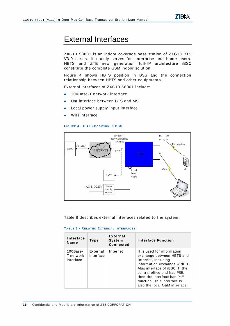
External Interfaces
ZXG10 S8001 is an indoor coverage base station of ZXG10 BTS V3.0 series. It mainly serves for enterprise and home users. HBTS and ZTE new generation full-IP architecture iBSC constitute the complete GSM indoor solution.
Figure 4 shows HBTS position in BSS and the connection relationship between HBTS and other equipments.
External interfaces of ZXG10 S8001 include:
100Base-T network interface
Um interface between BTS and MS
Local power supply input interface
WiFi interface
F I G U R E 4 - HBTS P O S I T I O N I N BSS
Table 8 describes external interfaces related to the system.
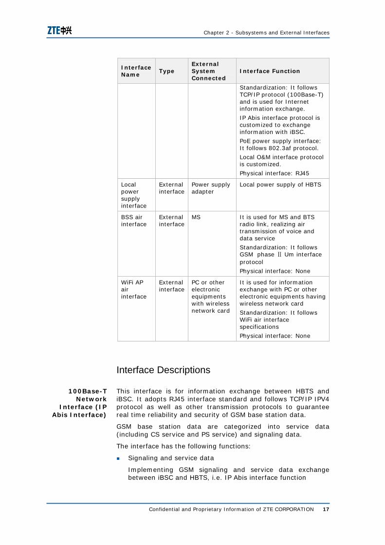
T AB L E 8 - R E L A T E D E X T E R N AL I N T E R F AC E S
Interface Name
Type External System Connected
Interface Function
100Base-T network interface
External interface
Internet
It is used for information exchange between HBTS and Internet, including information exchange with IP Abis interface of iBSC. If the central office end has PSE, then the interface has PoE function. This interface is also the local O&M interface.
Chapter 2 - Subsystems and External Interfaces
Confidential and Proprietary Information of ZTE CORPORATION 17
Interface Name
Type External System Connected
Interface Function
Standardization: It follows TCP/IP protocol (100Base-T) and is used for Internet information exchange.
IP Abis interface protocol is customized to exchange information with iBSC.
PoE power supply interface: It follows 802.3af protocol.
Local O&M interface protocol is customized.
Physical interface: RJ45
Local power supply interface
External interface
Power supply adapter
Local power supply of HBTS
BSS air interface
External interface
MS It is used for MS and BTS radio link, realizing air transmission of voice and data service
Standardization: It follows GSM phase Ⅱ Um interface protocol
Physical interface: None
WiFi AP air interface
External interface
PC or other electronic equipments with wireless network card
It is used for information exchange with PC or other electronic equipments having wireless network card
Standardization: It follows WiFi air interface specifications
Physical interface: None
Interface Descriptions
This interface is for information exchange between HBTS and iBSC. It adopts RJ45 interface standard and follows TCP/IP IPV4 protocol as well as other transmission protocols to guarantee real time reliability and security of GSM base station data.
GSM base station data are categorized into service data (including CS service and PS service) and signaling data.
The interface has the following functions:
Signaling and service data
Implementing GSM signaling and service data exchange between iBSC and HBTS, i.e. IP Abis interface function
100Base-T Network
Interface (IP Abis Interface)

ZXG10 S8001 (V1.1) In-Door Pico Cell Base Transceiver Station User Manual
18 Confidential and Proprietary Information of ZTE CORPORATION
Data transmission interface of other Internet equipments
This interface is used for information exchange between WiFi wireless network card of HBTS and other Internet equipments to provide radio data service for users. It follows TCP/IP IPV4 protocol.
Local O&M interface
This interface is used to connect HBTS and PC or HBTS and other local O&M terminals. Data transmission protocol is customized and follows TCP/IP IPV4 protocol.
PoE power supply interface
This interface provides PoE power supply when PSE equipment is configured in the central office end. It follows 802.3af protocol.
This interface connects with power supply adapter to provide safe DC voltage for HBTS. Input of the power supply adapter is 110 V AC/220 V AC. In the case of power failure, the built-in battery in power supply adapter provides power for HBTS to work with full load for 30 minutes.
This interface is used for wireless connection between MS and BTS to realize air transmission of voice and data service. It follows GSM phase II Um interface protocol.
This interface is used for information exchange with PC or other electronic equipments having radio network card, satisfying WiFi air interface specifications.
Local Power Supply
Interface
BSS Air Interface
WiFi Air Interface

Confidential and Proprietary Information of ZTE CORPORATION 19
C h a p t e r 3
Installation
This chapter describes the installation mode of ZXG10 S8001 HBTS.
Mounting Instructions
ZXG10 S8001 supports two installation modes:
Wall-mounted installation
Desktop Installation
Wall-Mounted Installation
For wall-mounted installation, the installation steps are as follows:
1. Fix the wall-mounted installation board on the wall with swell fixtures, as shown in Figure 5.
F I G U R E 5 – WAL L -M O U N T E D I N S T AL L AT I O N
1. Installation pin 2. Gourd hole
Steps

ZXG10 S8001 (V1.1) In-Door Pico Cell Base Transceiver Station User Manual
20 Confidential and Proprietary Information of ZTE CORPORATION
2. Align the installation pin at the bottom of S8001 to the gourd hole, and slowly lay the equipment to install it on the wall, as shown in Figure 5.
3. Figure 6 shows the HBTS after the wall-mounted installation is completed.
F I G U R E 6 – A W AL L -M O U N T E D S8001
END OF STEPS
Desktop Installation
There are slip-proof plastics feet at the bottom of S8001, which enables it to be placed on a horizontal desktop, as shown in Figure 7.

Chapter 3 - Installation
Confidential and Proprietary Information of ZTE CORPORATION 21
F I G U R E 7 – DE S K T O P I N S T AL L AT I O N
Antenna and Cable ports
Cables to be connected include:
Ethernet cable
Power cable
Connect these cables with corresponding external interfaces of ZXG10 S8001, as shown in Figure 8.
The antenna is installed before delivery, and can be adjusted within the range of 0˚ ~ 180˚ according to signal receiving conditions.
F I G U R E 8 – EX T E R N AL I N T E R F AC E S O F S8001
1. Power interface 2. Network interface 3. Antenna

ZXG10 S8001 (V1.1) In-Door Pico Cell Base Transceiver Station User Manual
22 Confidential and Proprietary Information of ZTE CORPORATION
Power Cable
For local power supply, connect the power supply adapter with AC power supply.
Ethernet Cable
The Ethernet cable is used to realize IP Abis and PoE. Connect the Ethernet cable with the network interface of S8001 directly.
Note:
If S8001 adopts PoE as the power supply mode, the HBTS gets power supply directly from the Ethernet cable.
Pay attention that the HBTS should be connected with a HUB that satisfies the IEEE802.3af PSE requirement. If the HUB is of old type and can not provide power supply, then a Remote Power Supply (RPS) should be added between the HUB and the HBTS.

Confidential and Proprietary Information of ZTE CORPORATION 23
C h a p t e r 4
Troubleshooting
This chapter classifies alarms and describes symptoms, fault causes, and troubleshooting methods for different kinds of possible faults.
Checking the Front Panel Indicators
The front panel indicators are:
Power supply indicator (PWR, green)
Running indicator (RUN, green)
Alarm indicator (ALARM, red)
Network interface indicator (LINK, green)
Users should check the status of indicators and troubleshoot if the alarm indicator is ON/blinking or other indicators show abnormal status.
Table 9 shows the normal running status and alarm conditions of the indicators.
T AB L E 9 – D E S C R I P T I O N O F I N D I C AT O R S O N FR O N T P AN E L
Color Name Meaning Working Mode Flash Rate
Power supply is connected ON Green POWER Power Supply Indicator Power supply is
disconnected OFF
Boot running 5 Hz Green RUN Running Indicator
Application running 2 Hz
Hardware error ON
DHCP fails to obtain IP address/ fails to access iBSC
5 Hz
Red ALARM Alarm Indicator
Serious alarm 2 Hz

ZXG10 S8001 (V1.1) In-Door Pico Cell Base Transceiver Station User Manual
24 Confidential and Proprietary Information of ZTE CORPORATION
Color Name Meaning Working Mode Flash Rate
Common alarm 1 Hz
Normal, no alarm OFF
Network port is normal, S8001 obtains IP address successfully and the control plane fails to establish link
ON
Network port is normal, S8001 obtains IP address successfully and the control plane establishes link successfully
1 Hz
Network port is normal,S8001 fails to obtain IP address
5 Hz
Green LINK LAPD Link Indicator
Network port is abnormal OFF
Classification of Alarms
Alarms are classified into the following categories:
Serious Alarm
Accessing BSC failure alarm (ALARM indicator flashes at 5 Hz, authentication failed or no connection response)
S8001 fails to obtain IP address automatically (ALARM indicator flashed at 5 Hz, LINK indicator flashes at 5 Hz)
No available frequency point alarm (ALARM indicator flashes at 2 Hz)
Hardware Error (ALARM indicator is ON)
Flash Memory error
Alarm of DSP WatchDog overflow
FPGA interface error
Common alarm
The control plane link is broken (ALARM indicator flashes at 1 Hz, LINK indicator is ON)
Chapter 4 - Troubleshooting
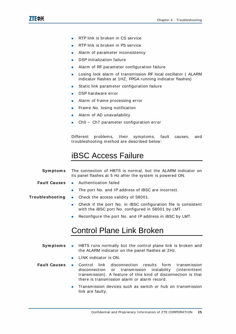
Confidential and Proprietary Information of ZTE CORPORATION 25
RTP link is broken in CS service
RTP link is broken in PS service
Alarm of parameter inconsistency
DSP initialization failure
Alarm of RF parameter configuration failure
Losing lock alarm of transmission RF local oscillator ( ALARM indicator flashes at 1HZ, FPGA running indicator flashes)
Static link parameter configuration failure
DSP hardware error
Alarm of frame processing error
Frame No. losing notification
Alarm of AD unavailability
Ch0 ~ Ch7 parameter configuration error
Different problems, their symptoms, fault causes, and troubleshooting method are described below:
iBSC Access Failure
The connection of HBTS is normal, but the ALARM indicator on its panel flashes at 5 Hz after the system is powered ON.
Authentication failed
The port No. and IP address of iBSC are incorrect.
Check the access validity of S8001.
Check if the port No. in iBSC configuration file is consistent with the iBSC port No. configured in S8001 by LMT.
Reconfigure the port No. and IP address in iBSC by LMT.
Control Plane Link Broken
HBTS runs normally but the control plane link is broken and the ALARM indicator on the panel flashes at 2Hz.
LINK indicator is ON.
Control link disconnection results form transmission disconnection or transmission instability (intermittent transmission). A feature of this kind of disconnection is that there is transmission alarm or alarm record.
Transmission devices such as switch or hub on transmission link are faulty.
Symptoms
Fault Causes
Troubleshooting
Symptoms
Fault Causes
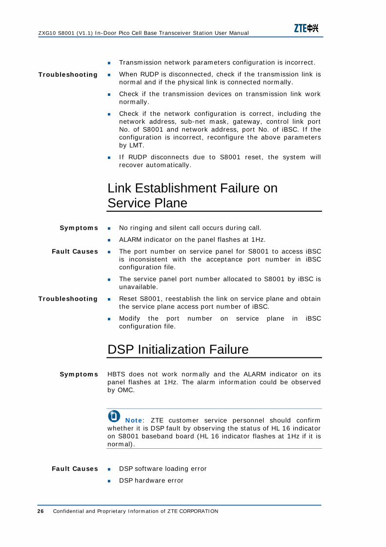
ZXG10 S8001 (V1.1) In-Door Pico Cell Base Transceiver Station User Manual
26 Confidential and Proprietary Information of ZTE CORPORATION
Transmission network parameters configuration is incorrect.
When RUDP is disconnected, check if the transmission link is normal and if the physical link is connected normally.
Check if the transmission devices on transmission link work normally.
Check if the network configuration is correct, including the network address, sub-net mask, gateway, control link port No. of S8001 and network address, port No. of iBSC. If the configuration is incorrect, reconfigure the above parameters by LMT.
If RUDP disconnects due to S8001 reset, the system will recover automatically.
Link Establishment Failure on Service Plane
No ringing and silent call occurs during call.
ALARM indicator on the panel flashes at 1Hz.
The port number on service panel for S8001 to access iBSC is inconsistent with the acceptance port number in iBSC configuration file.
The service panel port number allocated to S8001 by iBSC is unavailable.
Reset S8001, reestablish the link on service plane and obtain the service plane access port number of iBSC.
Modify the port number on service plane in iBSC configuration file.
DSP Initialization Failure
HBTS does not work normally and the ALARM indicator on its panel flashes at 1Hz. The alarm information could be observed by OMC.
Note: ZTE customer service personnel should confirm whether it is DSP fault by observing the status of HL 16 indicator on S8001 baseband board (HL 16 indicator flashes at 1Hz if it is normal).
DSP software loading error
DSP hardware error
Troubleshooting
Symptoms
Fault Causes
Troubleshooting
Symptoms
Fault Causes

Chapter 4 - Troubleshooting
Confidential and Proprietary Information of ZTE CORPORATION 27
If the indicator of power ON initialization is OFF, the problem may result from abnormal frame disconnection for 26 MHz clock loss.
Reset DSP, the system reloads CHP automatically and reinitializes the parameters.
Download the software version of DSP again.
If it is because of hardware error, replace the baseband board of S8001.
If it is because of abnormal frame disconnection for 26 MHz clock loss, reset S8001 first; if the problem persists, it is recommended to replace the RF board of S8001.
Flash Memory Failure
It fails to download or load software version and record S8001 event log. S8001 may not work properly and the ALARM indicator on panel is continuously ON. Check the alarm information by OMC.
Excessive programming times on FLASH
Reading/Writing error
Software checksum error
Reset S8001 and reload software version, observe if the fault is recovered. Otherwise, replace S8001.
Watchdog of DSP Overflows
System resets DSP automatically, loading the program and initializing DSP again. If this fault occurs frequently, the ALARM indicator is continuously ON. The alarm information could be observed by OMC.
Note: ZTE customer service personnel should confirm whether it is DSP fault by observing the status of HL 16 indicator on S8001 baseband board (HL 16 indicator flashes at 1Hz if it is normal).
Error in the DSP running program leads to failure or improper running of DSP.
Reset DSP again, load DSP software version, and reconfigure CHP parameters.
Re-download DSP software version.
Troubleshooting
Symptoms
Fault Causes
Troubleshooting
Symptoms
Fault Causes
Troubleshooting

ZXG10 S8001 (V1.1) In-Door Pico Cell Base Transceiver Station User Manual
28 Confidential and Proprietary Information of ZTE CORPORATION
Frequency Not Available Alarm
HBTS fails to find available frequency point. The ALARM indicator on its panel flashes at 2Hz. The alarm information could be observed by OMC.
Frequency auto-search failure
Search timeout
iBSC does not provide frequency point.
System automatically originates frequency search regularly.
Change the search range of frequency point.
Assign available frequency point from iBSC.
Use appointed frequency point.
Local Oscillator of Transmission Channel Losing Lock Alarm
S8001 could not work normally, the ALARM indicator on its panel flashes at 1Hz. The alarm information could be observed by OMC.
Note: ZTE customer service personnel should confirm whether the local oscillator of transmission channel has lost the lock by observing if HL 10 indicator on S8001 baseband board flashes at 1Hz (HL 10 is ON if it is normal).
Clock signal is unstable or phase locked loop is faulty.
Reset S8001 and observe if HL10 indicator is ON.
Replace baseband board.
Link Parameter Configuration Failure
The system cannot work properly because it fails to configure link parameters after S8001 startup.
The ALARM indicator flashes at 1Hz.
ALARM indicator and LINK indicator both flash at 5Hz.
The alarm information could be observed by OMC.
Symptoms
Fault Causes
Troubleshooting
Symptoms
Fault Causes
Troubleshooting
Symptoms

Chapter 4 - Troubleshooting
Confidential and Proprietary Information of ZTE CORPORATION 29
Note: For the link parameter configuration of S8001, users could choose obtaining an IP address automatically or static link parameter configuration. While choosing to obtain an IP automatically, the local IP address, subnet mask and gateway of S8001 could be obtained automatically. The ALARM indicator and LINK indicator both flash at 5 Hz when fault appears. While choosing static link parameter configuration, the local IP address, subnet mask and gateway information need to be configured manually. The ALARM indicator flashes at 1 Hz when fault appears.
While choosing to obtain an IP address automatically, the fault may be caused by DHCP server error.
While choosing static link parameter configuration, the fault may be caused by LMT connection failure, flash writing failure, or timeout.
The transmission devices on transmission link such as switch, hub, or transmission link itself are faulty.
The configured local control link port number., service link port number. of S8001, and the IP address and port number. of accessed iBSC are incorrect.
In the case of obtaining an IP address automatically, check if DHCP server is normal. If the fault still exists, configure the local IP address, subnet mask, and gateway by the static link parameter of LMT.
In the case of static link parameter configuration, set the IP address of host machine in the same network segment as the default IP address of S8001, and reestablish connection manually again; if flash writing is failed or timeout, reset S8001.
Check if the transmission link is normal and if the physical link is connected firmly.
Check if the transmission devices on transmission link work normally.
Note: Find out the fault occurs in which mode by the ALARM indicator and LINK indicator on S8001 panel.
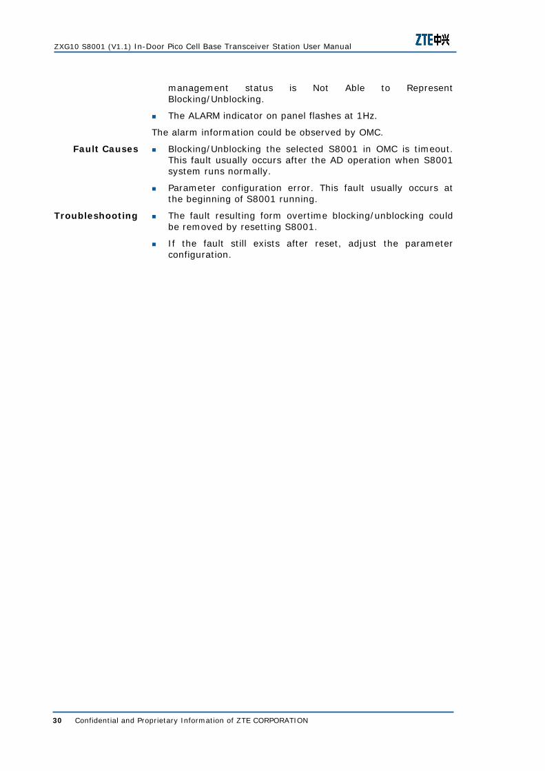
AD Unavailability Alarm
It fails to block/unblock S8001.
In dynamic data management in OMC, the operation status is Disabled, the availability status is Unavailable and the
Fault Causes
Troubleshooting
Symptoms
ZXG10 S8001 (V1.1) In-Door Pico Cell Base Transceiver Station User Manual
30 Confidential and Proprietary Information of ZTE CORPORATION
management status is Not Able to Represent Blocking/Unblocking.
The ALARM indicator on panel flashes at 1Hz.
The alarm information could be observed by OMC.
Blocking/Unblocking the selected S8001 in OMC is timeout. This fault usually occurs after the AD operation when S8001 system runs normally.
Parameter configuration error. This fault usually occurs at the beginning of S8001 running.
The fault resulting form overtime blocking/unblocking could be removed by resetting S8001.
If the fault still exists after reset, adjust the parameter configuration.
Fault Causes
Troubleshooting
Confidential and Proprietary Information of ZTE CORPORATION 31
C h a p t e r 5
Solutions
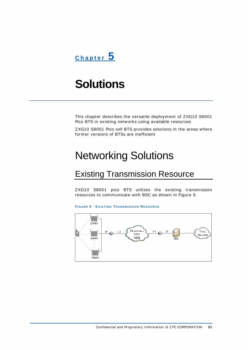
This chapter describes the versatile deployment of ZXG10 S8001 Pico BTS in existing networks using available resources
ZXG10 S8001 Pico cell BTS provides solutions in the areas where former versions of BTSs are inefficient
Networking Solutions Existing Transmission Resource
ZXG10 S8001 pico BTS utilizes the existing transmission resources to communicate with BSC as shown in Figure 9.
F I G U R E 9 - E X I S T I N G TR AN S M I S S I O N R E S O U R C E
ZXG10 S8001 (V1.1) In-Door Pico Cell Base Transceiver Station User Manual
32 Confidential and Proprietary Information of ZTE CORPORATION
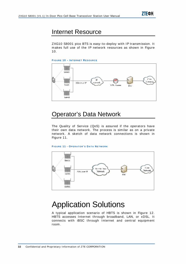
Internet Resource
ZXG10 S8001 pico BTS is easy-to-deploy with IP transmission. It makes full use of the IP network resources as shown in Figure 10.
F I G U R E 10 – IN T E R N E T R E S O U R C E
Operator’s Data Network
The Quality of Service (QoS) is assured if the operators have their own data network. The process is similar as on a private network. A sketch of data network connections is shown in Figure 11.
F I G U R E 11 - OP E R A T O R ’ S D AT A N E T W O R K
Application Solutions A typical application scenario of HBTS is shown in Figure 12. HBTS accesses Internet through broadband, LAN, or xDSL. It connects with iBSC through Internet and central equipment room.

Chapter 5 - Solutions
Confidential and Proprietary Information of ZTE CORPORATION 33
F I G U R E 12 - TY P I C AL HBTS AP P L I C AT I O N
Group users have their own LAN. The network bandwidth is much broader and multiple home BTSs are connected. iBSC is placed in the LAN and connected to MSC by dedicated lines, which provides reliable and secure services for group users, as shown in Figure 13.
F I G U R E 13 - AP P L I C AT I O N S C E N AR I O O F HBTS GR O U P US E R S
MSC
IBSC
HOME BTS
HOME BTS
PC
HOME BTS
MS
� �Dedicated line
Minor users access public network through ADSL. iBSC is connected to public network, thus connection is established between Home BTS and iBSC. In this connection mode, data security is threatened due to the public network openness. Thus Home BTS adopts IPSec technology and establishes secure connection with iBSC to enhance data security as shown in Figure 14.

ZXG10 S8001 (V1.1) In-Door Pico Cell Base Transceiver Station User Manual
34 Confidential and Proprietary Information of ZTE CORPORATION
F I G U R E 14 - AP P L I C AT I O N S C E N AR I O O F HBTS M I N O R US E R S
Family Application Solution
ZXG10 S8001 pico BTS provides solution for different family applications in the following ways:
Ultra low transmission power, compliant with USA FCC, IP access, makes use of users wideband resource
IPSec encryption for private information security
Supports EDGE/Wifi access, provides wideband mobile service
F I G U R E 15 - FAM I L Y AP P L I C AT I O N S O L U T I O N
Indoor Coverage Solution
ZXG10 S8001 pico BTS provides solutions for indoor coverage in the following ways:
More traffic compensation and improved frequency utilization because 70% mobile voice traffic and 60% mobile data traffic is from indoor

Chapter 5 - Solutions
Confidential and Proprietary Information of ZTE CORPORATION 35
Fast deployment and cost effective as compared to Distributed Antenna System (DAS)
IPSec encryption for information and network security
Green BTS compliance with health friendliness
F I G U R E 16 - IN D O O R C O V E R A G E S O L U T I O N
Hot Spot Coverage Solution
ZXG10 S8001 pico BTS provides solutions for hot spot coverage in the following ways:
At hotspot with good network condition like stadium, S8001 replaces mobile BTS system

ZXG10 S8001 (V1.1) In-Door Pico Cell Base Transceiver Station User Manual
36 Confidential and Proprietary Information of ZTE CORPORATION
F I G U R E 17 - HO T S P O T CO V E R A G E S O L U T I O N
Mobile BTS system has the following shortcomings:
Outdoor penetration coverage and interference with nearby BTS to some extent
Requires power supply and transmission resources
ZXG10 S8001 has the following advantages:
Small size and light weight; portable and quick deployment
Power over Ethernet (PoE); plug and play
IP transmission saves transmission cost
Solves the problem of lack of frequency resource
T AB L E 10 – CO M P AR I S O N O F M O B I L E BTS S Y S T E M W I T H S8001
Properties ZXG10 S8001 Mobile BTS system
Power supply PoE and local AC 380V
Transmission IP E1; based on transmission condition
Coverage Indoor direct coverage Outdoor penetration coverage
Capacity Cascaded networking for expansion
Limited by volume; generally S222
Hub
UTP

Chapter 5 - Solutions
Confidential and Proprietary Information of ZTE CORPORATION 37
Blind Area Solution
ZXG10 S8001 pico BTS provides solutions for blind area in the following ways:
Being indoor BTS, it covers all the corners and no area is left blind.
Easy-to-move to a convenient place time to time because of ultra small size.
F I G U R E 18 - BL I N D AR E A S O L U T I O N
Enterprise Application Solution
ZXG10 S8001 pico BTS provides solutions for enterprise application in the following ways:
Utilizes enterprise network to setup internal communication system, saving engineering and maintenance cost
WiFi and easy adoption makes wireless office communication possible, without telephone and network cable
Value Added Services (VAS) improve ARPU

ZXG10 S8001 (V1.1) In-Door Pico Cell Base Transceiver Station User Manual
38 Confidential and Proprietary Information of ZTE CORPORATION
F I G U R E 19 - EN T E R P R I S E AP P L I C AT I O N S O L U T I O N
Special Applications Solution
Satellite with ZXG10 S8001 pico BTS provides solution for special applications in the following ways:
Emergency communication, like medical relief and fire brigade
Boat and airplane communication
F I G U R E 20 - SP E C I AL AP P L I C AT I O N S O L U T I O N
Confidential and Proprietary Information of ZTE CORPORATION 39
A p p e n d i x A
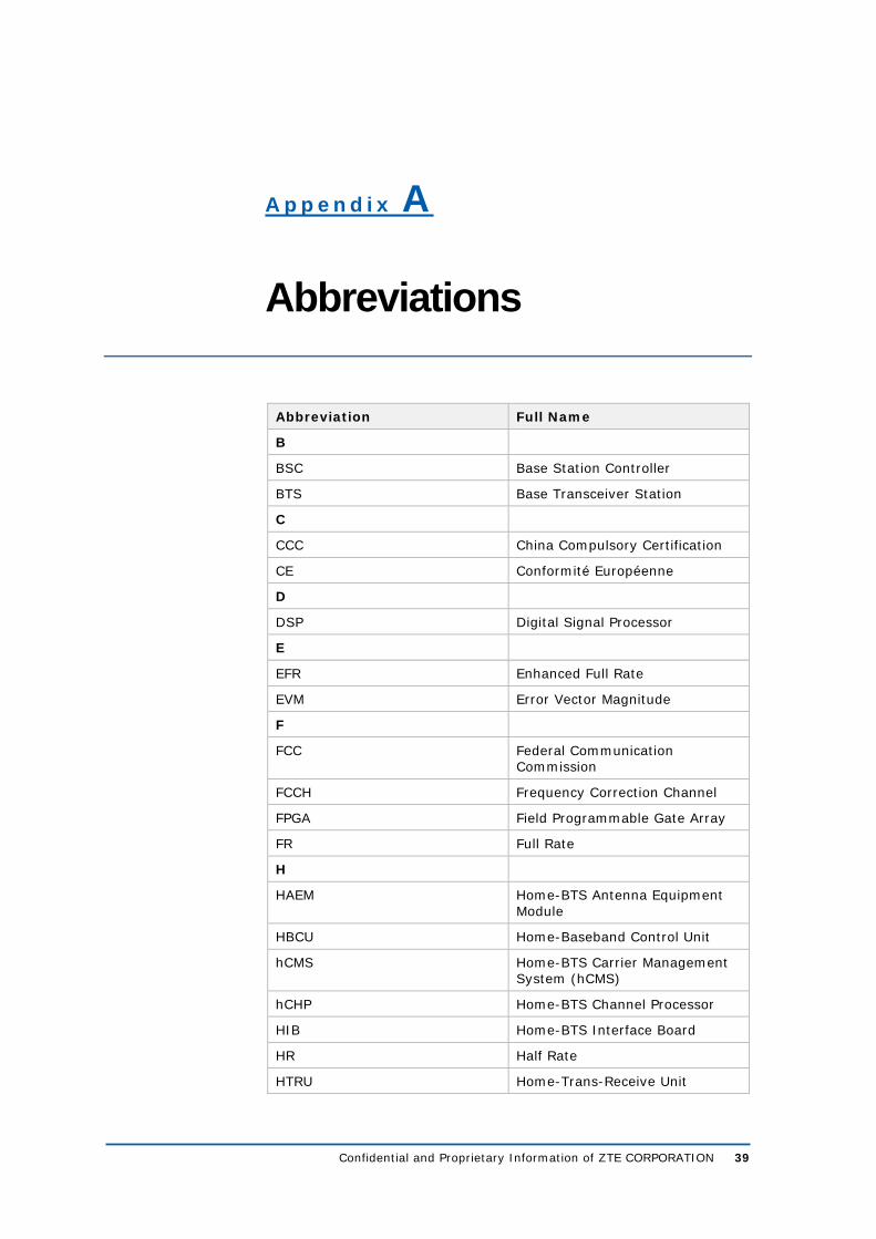
Abbreviations
Abbreviation Full Name
B
BSC Base Station Controller
BTS Base Transceiver Station
C
CCC China Compulsory Certification
CE Conformité Européenne
D
DSP Digital Signal Processor
E
EFR Enhanced Full Rate
EVM Error Vector Magnitude
F
FCC Federal Communication Commission
FCCH Frequency Correction Channel
FPGA Field Programmable Gate Array
FR Full Rate
H
HAEM Home-BTS Antenna Equipment Module
HBCU Home-Baseband Control Unit
hCMS Home-BTS Carrier Management System (hCMS)
hCHP Home-BTS Channel Processor
HIB Home-BTS Interface Board
HR Half Rate
HTRU Home-Trans-Receive Unit

ZXG10 S8001 (V1.1) In-Door Pico Cell Base Transceiver Station User Manual
40 Confidential and Proprietary Information of ZTE CORPORATION
Abbreviation Full Name
L
LED Light Emmiting Diode
O
OMC Operation and Maintenance Center
P
PCB Printed Circuit Board
PoE Power over Ethernet
R
RF Radio Frequency
RMS Root Mean Square
U
UMS Unified network Management System
V
VAS Value Added Service

Confidential and Proprietary Information of ZTE CORPORATION 41
A p p e n d i x B
Figures
Figure 1 – Appearance of HBTS ............................................2
Figure 2 - System Architecture .............................................4
Figure 3 - ZXG10 8000 Family............................................ 12
Figure 4 - HBTS Position in BSS.......................................... 16
Figure 5 – Wall-Mounted Installation ................................... 19
Figure 6 – A Wall-Mounted S8001....................................... 20
Figure 7 – Desktop Installation ........................................... 21
Figure 8 – External Interfaces of S8001 ............................... 21
Figure 9 - Existing Transmission Resource............................ 31
Figure 10 – Internet Resource ............................................ 32
Figure 11 - Operator’s Data Network ................................... 32
Figure 12 - Typical HBTS Application ................................... 33
Figure 13 - Application Scenario of HBTS Group Users ........... 33
Figure 14 - Application Scenario of HBTS Minor Users ............ 34
Figure 15 - Family Application Solution ................................ 34
Figure 16 - Indoor Coverage Solution .................................. 35
Figure 17 - Hot Spot Coverage Solution ............................... 36
Figure 18 - Blind Area Solution ........................................... 37
Figure 19 - Enterprise Application Solution ........................... 38
Figure 20 - Special Application Solution ............................... 38

ZXG10 S8001 (V1.1) In-Door Pico Cell Base Transceiver Station User Manual
42 Confidential and Proprietary Information of ZTE CORPORATION
This page is intentionally blank

Confidential and Proprietary Information of ZTE CORPORATION 43
Tables
Table 1 Manual Summary ....................................................i
Table 2 Typographical Conventions ...................................... ii
Table 3 Mouse Operation Conventions ................................. iii
Table 4 – Usage Explanation of the Hazardous Substances in S8001...............................................................................v
Table 5 - Environmental Conditions.......................................2
Table 6 - ZXG10 S8001 Subsystems .....................................4
Table 7 - ZXG10 S8001 Interface Descriptions........................5
Table 8 - Related External Interfaces................................... 16
Table 9 – Description of Indicators on Front Panel ................. 23
Table 10 – Comparison of Mobile BTS System with S8001 ...... 36
ZXG10 S8001 (V1.1) In-Door Pico Cell Base Transceiver Station User Manual
44 Confidential and Proprietary Information of ZTE CORPORATION
This page is intentionally blank.

Confidential and Proprietary Information of ZTE CORPORATION 45
Index
100Base-T ............ 5, 7, 16, 17 8PSK.................. 4, 10, 11, 14 A/D conversion ............. 14, 15 clock loss ...........................27 CS service............... 14, 17, 25 D/A...................................14 FPGA.................................13 GMSK................. 4, 10, 11, 14 GPRS ............................ 7, 11 LED............................... 1, 11 LMT ....................... 25, 26, 29
Modulation......................... 11 PDTCH .............................. 11 Power Control .................... 11 PS service............... 14, 17, 25 PSE .................................. 16 TCP/IP ................... 16, 17, 18 temperature................... 2, 15 Transmission. 2, 11, 25, 26, 28,
31, 36 voltage.......................... 3, 18 wall-mounted ................. 1, 19


![ZXG10 iBSC (V6[1].00) board](https://img.dokumen.tips/doc/110x75/55cf98a0550346d03398bb35/zxg10-ibsc-v6100-board.jpg)


![03d ZXG10 B8018 Hardware Architecture[1]](https://img.dokumen.tips/doc/110x75/577cc2ad1a28aba711945a53/03d-zxg10-b8018-hardware-architecture1.jpg)