Embed Size (px)
Citation preview

Operation and Maintenance Instructions ZX-Series Large Bore Lathes Models GH-1440ZX
GH-1640ZX/1660ZX GH-1860ZX/1880ZX GH-2280ZX
Model GH-1440ZX shown
* For ZX-Series Lathes Parts List & Electrical Diagrams, see document M-321910-1
JET
427 New Sanford Road LaVergne, TN 37086 Part No. M-321910 Ph.: 800-274-6848 Revision J1 10/2017 www.jettools.com Copyright © 2017 JET

2
1.0 Warranty and service JET warrants every product it sells against manufacturers’ defects. If one of our tools needs service or repair, please contact Technical Service by calling 1-800-274-6846, 8AM to 5PM CST, Monday through Friday.
Warranty Period The general warranty lasts for the time period specified in the literature included with your product or on the official JET branded website.
• JET products carry a limited warranty which varies in duration based upon the product. (See chart below) • Accessories carry a limited warranty of one year from the date of receipt. • Consumable items are defined as expendable parts or accessories expected to become inoperable within a
reasonable amount of use and are covered by a 90 day limited warranty against manufacturer’s defects.
Who is Covered This warranty covers only the initial purchaser of the product from the date of delivery.
What is Covered This warranty covers any defects in workmanship or materials subject to the limitations stated below. This warranty does not cover failures due directly or indirectly to misuse, abuse, negligence or accidents, normal wear-and-tear, improper repair, alterations or lack of maintenance.
Warranty Limitations Woodworking products with a Five Year Warranty that are used for commercial or industrial purposes default to a Two Year Warranty. Please contact Technical Service at 1-800-274-6846 for further clarification.
How to Get Technical Support Please contact Technical Service by calling 1-800-274-6846. Please note that you will be asked to provide proof of initial purchase when calling. If a product requires further inspection, the Technical Service representative will explain and assist with any additional action needed. JET has Authorized Service Centers located throughout the United States. For the name of an Authorized Service Center in your area call 1-800-274-6846 or use the Service Center Locator on the JET website.
More Information JET is constantly adding new products. For complete, up-to-date product information, check with your local distributor or visit the JET website.
How State Law Applies This warranty gives you specific legal rights, subject to applicable state law.
Limitations on This Warranty JET LIMITS ALL IMPLIED WARRANTIES TO THE PERIOD OF THE LIMITED WARRANTY FOR EACH PRODUCT. EXCEPT AS STATED HEREIN, ANY IMPLIED WARRANTIES OF MERCHANTABILITY AND FITNESS FOR A PARTICULAR PURPOSE ARE EXCLUDED. SOME STATES DO NOT ALLOW LIMITATIONS ON HOW LONG AN IMPLIED WARRANTY LASTS, SO THE ABOVE LIMITATION MAY NOT APPLY TO YOU. JET SHALL IN NO EVENT BE LIABLE FOR DEATH, INJURIES TO PERSONS OR PROPERTY, OR FOR INCIDENTAL, CONTINGENT, SPECIAL, OR CONSEQUENTIAL DAMAGES ARISING FROM THE USE OF OUR PRODUCTS. SOME STATES DO NOT ALLOW THE EXCLUSION OR LIMITATION OF INCIDENTAL OR CONSEQUENTIAL DAMAGES, SO THE ABOVE LIMITATION OR EXCLUSION MAY NOT APPLY TO YOU. JET sells through distributors only. The specifications listed in JET printed materials and on official JET website are given as general information and are not binding. JET reserves the right to effect at any time, without prior notice, those alterations to parts, fittings, and accessory equipment which they may deem necessary for any reason whatsoever. JET® branded products are not sold in Canada by JPW Industries, Inc.
Product Listing with Warranty Period 90 Days – Parts; Consumable items 1 Year – Motors; Machine Accessories 2 Year – Metalworking Machinery; Electric Hoists, Electric Hoist Accessories; Woodworking Machinery used for industrial or commercial purposes 5 Year – Woodworking Machinery Limited Lifetime – JET Parallel clamps; VOLT Series Electric Hoists; Manual Hoists; Manual Hoist Accessories; Shop Tools; Warehouse & Dock products; Hand Tools; Air Tools
NOTE: JET is a division of JPW Industries, Inc. References in this document to JET also apply to JPW Industries, Inc., or any of its successors in interest to the JET brand.

3
2.0 Table of Contents 1.0 Warranty and service ..................................................................................................................................... 2 2.0 Table of Contents ........................................................................................................................................... 3 3.0 IMPORTANT SAFETY INSTRUCTIONS ....................................................................................................... 4 4.0 Dimensions and mounting hole centers ......................................................................................................... 5 5.0 Specifications ................................................................................................................................................. 6
5.1 Specifications: 14-inch lathe ....................................................................................................................... 6 5.2 Specifications: 16-inch lathe ....................................................................................................................... 7 5.3 Specifications: 18-inch lathe ....................................................................................................................... 8 5.4 Specifications: 22-inch lathe ....................................................................................................................... 9
6.0 General Description and Nomenclature ....................................................................................................... 10 7.0 Unpacking .................................................................................................................................................... 12
7.1 Contents of shipping container ................................................................................................................. 12 8.0 Installation .................................................................................................................................................... 13
8.1 Leveling the lathe ..................................................................................................................................... 13 8.2 Completing installation ............................................................................................................................. 13 8.3 Chuck preparation (three-jaw) .................................................................................................................. 14 8.4 Break-in period ......................................................................................................................................... 14
9.0 Maintenance/Lubrication ............................................................................................................................... 15 10.0 Coolant preparation .................................................................................................................................... 16 11.0 Electrical connections ................................................................................................................................ 16
11.1 Conversion to 460 volt operation ............................................................................................................. 17 12.0 Controls ...................................................................................................................................................... 17 13.0 Operation ................................................................................................................................................... 19
13.1 Tool setup ............................................................................................................................................... 20 13.2 Feed and thread selection ...................................................................................................................... 20 13.3 Thread cutting ........................................................................................................................................ 20
14.0 Adjustments ............................................................................................................................................... 20 14.1 Chuck jaw reversal ................................................................................................................................. 20 14.2 Gib adjustments ..................................................................................................................................... 21 14.3 Tailstock off-set ...................................................................................................................................... 21 14.4 Removing gap bridge ............................................................................................................................. 21 14.5 Installing gap bridge ............................................................................................................................... 22 14.6 Belt replacement/adjustment .................................................................................................................. 22 14.7 Aligning tailstock to headstock ............................................................................................................... 22 14.8 Cross slide nut adjustment ..................................................................................................................... 22 14.9 Shear pin replacement ........................................................................................................................... 22 14.10 Steady rest adjustment ......................................................................................................................... 22 14.11 Follow rest adjustment ......................................................................................................................... 23 14.12 Carriage stops ...................................................................................................................................... 23
15.0 Lubrication schedule and general maintenance ......................................................................................... 24 16.0 Reference tables ........................................................................................................................................ 25
16.1 Inch Lead And Feed ............................................................................................................................... 25

4
3.0 IMPORTANT SAFETY INSTRUCTIONS 1. Read and understand the entire owner’s manual before attempting assembly or operation.
2. Read and understand the warnings posted on the machine and in this manual. Failure to comply with all of these warnings may cause serious injury.
3. Replace the warning labels if they become obscured or removed.
4. This lathe is designed and intended for use by properly trained and experienced personnel only. If you are not familiar with the proper and safe operation of a lathe, do not use until proper training and knowledge have been obtained.
5. Do not use this lathe for other than its intended use. If used for other purposes, JET disclaims any real or implied warranty and holds itself harmless from any injury that may result from that use.
6. Always wear approved safety glasses/face shields while using this lathe. Everyday eyeglasses only have impact resistant lenses; they are not safety glasses.
7. Before operating this lathe, remove tie, rings, watches and other jewelry, and roll sleeves up past the elbows. Remove all loose clothing and confine long hair. Non-slip footwear or anti-skid floor strips are recommended. Do not wear gloves.
8. Wear ear protectors (plugs or muffs) during extended periods of operation.
9. CALIFORNIA PROPOSITION 65 WARNING: This product contains chemicals known to the State of California to cause cancer, or birth defects or other reproductive harm.
10. This product, when used for welding, cutting, or working with metal, produces fumes, gases, or dusts which contain chemicals known to the State of California to cause birth defects and, in some cases, cancer. (California Health and Safety Code Section 25249.5 et seq.)
11. Do not operate this machine while tired or under the influence of drugs, alcohol or any medication.
12. Make certain the switch is in the OFF position before connecting the machine to the power supply.
13. Make certain the machine is properly grounded.
14. Make all machine adjustments or maintenance with the machine unplugged from the power source.
15. Remove adjusting keys and wrenches. Form a habit of checking to see that keys and adjusting wrenches are removed from the machine before turning it on.
16. Keep safety guards in place at all times when the machine is in use. If removed for maintenance purposes, use extreme caution and replace the guards immediately.
17. Check damaged parts. Before further use of the machine, a guard or other part that is damaged should be carefully checked to determine that it will operate properly and perform its intended function. Check for alignment of moving parts, binding of moving parts, breakage of parts, mounting and any other conditions that may affect its operation. A guard or other part that is damaged should be properly repaired or replaced.
18. Provide for adequate space surrounding work area and non-glare, overhead lighting.
19. Keep the floor around the machine clean and free of scrap material, oil and grease.
20. Keep visitors a safe distance from the work area. Keep children away.
21. Make your workshop child proof with padlocks, master switches or by removing starter keys.
22. Give your work undivided attention. Looking around, carrying on a conversation and “horse-play” are careless acts that can result in serious injury.
23. Maintain a balanced stance at all times so that you do not fall or lean against moving parts. Do not overreach or use excessive force to perform any machine operation. Never force the cutting action.
24. Use the right tool at the correct speed and feed rate. Do not force a tool or attachment to do a job for which it was not designed. The right tool will do the job better and safer.
25. Use recommended accessories; improper accessories may be hazardous.

5
26. Maintain tools with care. Keep cutting tools sharp and clean for the best and safest performance. Follow instructions for lubricating and changing accessories.
27. Do not attempt to adjust or remove tools during operation.
28. Turn off the machine and disconnect from power before cleaning. Use a brush to remove shavings or debris — do not use your hands.
29. Do not stand on the machine. Serious injury could occur if the machine tips over.
30. Never leave the machine running unattended. Turn the power off and do not leave the machine until it comes to a complete stop.
31. Remove loose items and unnecessary work pieces from the area before starting the machine.
Familiarize yourself with the following safety notices used in this manual:
This means that if precautions are not heeded, it may result in minor injury and/or possible machine damage.
This means that if precautions are not heeded, it may result in serious injury or possibly even death.
4.0 Dimensions and mounting hole centers
Figure 1

6
Specifications were current at the time this manual was published, but because of our policy of continuous improvement, JET reserves the right to change specifications at any time and without prior notice, without incurring obligations.
5.0 Specifications 5.1 Specifications: 14-inch lathe Model Number ...................................................................................................................................... GH-1440ZX Stock Number ............................................................................................................................................. 321910 Capacities: Swing over Bed (in.) ............................................................................................................................................ 14 Swing over Cross Slide (in.) ............................................................................................................................ 7-5/8 Swing Through Gap (in.) ............................................................................................................................... 23-5/8 Length of Gap (in.) .............................................................................................................................................. 12 Distance between Centers (in.) ........................................................................................................................... 40 Headstock: Spindle Bore (in.) ............................................................................................................................................ 3-1/8 Spindle Mount ................................................................................................................................................. D1-8 Spindle Taper with Sleeve ................................................................................................................... MT-7(MT-5) Number of Spindle Speeds ................................................................................................................................. 12 Range of Spindle Speeds (RPM) ........................................................................................................... 42 to 1800 Gearbox: Number of Longitudinal and Cross Feeds ...................................................................................................... 46/31 Range of Longitudinal Feeds (in./rev.) ......................................................................................... 0.0015 to 0.0900 Range of Cross Feeds (in./rev.) ................................................................................................... 0.0010 to 0.0360 Number of Inch Threads ..................................................................................................................................... 61 Range of Inch Threads (in.) ................................................................................................................... 1-5/8 to 72 Number of Metric Threads .................................................................................................................................. 24 Range of Metric Threads (mm) ............................................................................................................ 0.50 to 20.0 Number of Diametral Threads ............................................................................................................................. 45 Range of Diametral Threads ............................................................................................................. 3-1/4 – 96DP Number of Module Threads ............................................................................................................................... 20 Range of Module Threads .................................................................................................................. 0.25 – 10MP Compound and Carriage: Maximum Compound Slide Travel (in.) ........................................................................................................... 5-1/8 Maximum Cross Slide Travel (in.) ......................................................................................................................... 9 Carriage Travel (in.) ............................................................................................................................................ 36 Tailstock: Tailstock Spindle Travel (in.) ................................................................................................................................. 6 Tailstock Taper ................................................................................................................................................ MT-4 Steady Rest Capacity (in.) .......................................................................................................................... 3/8 to 7 Follow Rest Capacity (in.) ..................................................................................................................... 1/2 to 3-1/2 Width of Bed (in.) .......................................................................................................................................... 13-1/8 Overall Dimensions (in.)(LxWxH) ................................................................................ 91-5/16 x 41-5/16 x 50-5/16 Motor ..................................................................................................... 7-1/2HP, 3PH, 230/460V (prewired 230V) Approximate Net Weight (lbs.) ........................................................................................................................ 4667

7
5.2 Specifications: 16-inch lathe Model Number ............................................................................... GH-1640ZX................................... GH-1660ZX Stock Number .......................................................................................321930.......................................... 321940 Capacities: Swing over Bed (in.) ......................................................................................16.................................................. 16 Swing over Cross Slide (in.) ..........................................................................10.................................................. 10 Swing Through Gap (in.) ...............................................................................25.................................................. 25 Length of Gap (in.) ........................................................................................12.................................................. 12 Distance between Centers (in.) .....................................................................40.................................................. 60 Headstock: Spindle Bore (in.) ..................................................................................... 3-1/8.............................................. 3-1/8 Spindle Mount ........................................................................................... D1-8.............................................. D1-8 Spindle Taper with Sleeve ............................................................ MT-7(MT-5)................................... MT-7(MT-5) Number of Spindle Speeds ...........................................................................12.................................................. 12 Range of Spindle Speeds (RPM) .....................................................25 to 1800..................................... 25 to 1800 Gearbox: Number of Longitudinal and Cross Feeds ................................................46/31............................................. 46/31 Range of Longitudinal Feeds (in./rev.) ...................................0.0015 to 0.0900........................... 0.0015 to 0.0900 Range of Cross Feeds (in./rev.) .............................................0.0010 to 0.0360........................... 0.0010 to 0.0360 Number of Inch Threads ...............................................................................61.................................................. 61 Range of Inch Threads (in.) ............................................................ 1-5/8 to 72..................................... 1-5/8 to 72 Number of Metric Threads ............................................................................24.................................................. 24 Range of Metric Threads (mm) ......................................................0.50 to 20.0................................... 0.50 to 20.0 Number of Diametral Threads .......................................................................45.................................................. 45 Range of Diametral Threads ....................................................... 3-1/4 – 96DP................................. 3-1/4 – 96DP Number of Module Threads ..........................................................................20.................................................. 20 Range of Module Threads ............................................................ 0.25 – 10MP.................................. 0.25 – 10MP Compound and Carriage: Maximum Compound Slide Travel (in.) .................................................... 5-1/8.............................................. 5-1/8 Maximum Cross Slide Travel (in.) ...................................................................9.................................................... 9 Carriage Travel (in.) ......................................................................................36.................................................. 55 Tailstock: Tailstock Spindle Travel (in.) ...........................................................................6.................................................... 6 Tailstock Taper ......................................................................................... MT-4.............................................. MT-4 Steady Rest Capacity (in.) ....................................................................3/8 to 7.......................................... 3/8 to 7 Follow Rest Capacity (in.) .............................................................. 1/2 to 3-1/2.................................... 1/2 to 3-1/2 Width of Bed (in.) ................................................................................... 13-1/8............................................ 13-1/8 Overall Dimensions (in.)(LxWxH) .......................... 91-5/16 x 41-5/16 x 50-5/8.......... 111-3/8 x 41-5/16 x 50-5/8 Motor ........................................................................ 7-1/2HP, 3Ph, 230/460V*.............. 7-1/2HP, 3Ph, 230/460V* Approximate Net Weight (lbs.) ..................................................................4689.............................................. 5218
*pre-wired 230V
8
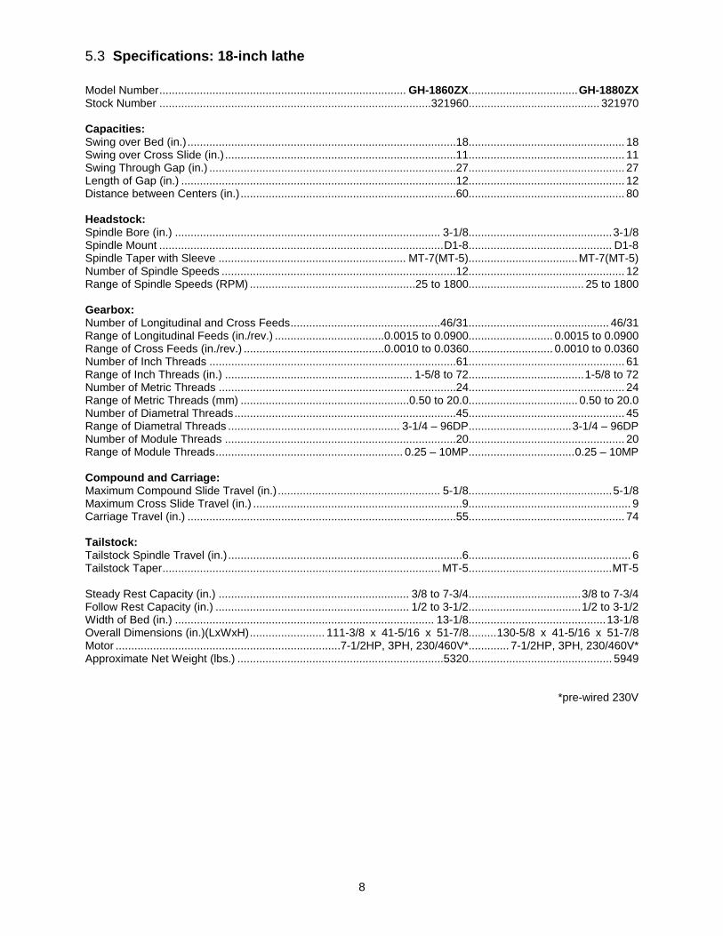
5.3 Specifications: 18-inch lathe Model Number ............................................................................... GH-1860ZX................................... GH-1880ZX Stock Number .......................................................................................321960.......................................... 321970 Capacities: Swing over Bed (in.) ......................................................................................18.................................................. 18 Swing over Cross Slide (in.) ..........................................................................11.................................................. 11 Swing Through Gap (in.) ...............................................................................27.................................................. 27 Length of Gap (in.) ........................................................................................12.................................................. 12 Distance between Centers (in.) .....................................................................60.................................................. 80 Headstock: Spindle Bore (in.) ..................................................................................... 3-1/8.............................................. 3-1/8 Spindle Mount ........................................................................................... D1-8.............................................. D1-8 Spindle Taper with Sleeve ............................................................ MT-7(MT-5)................................... MT-7(MT-5) Number of Spindle Speeds ...........................................................................12.................................................. 12 Range of Spindle Speeds (RPM) .....................................................25 to 1800..................................... 25 to 1800 Gearbox: Number of Longitudinal and Cross Feeds ................................................46/31............................................. 46/31 Range of Longitudinal Feeds (in./rev.) ...................................0.0015 to 0.0900........................... 0.0015 to 0.0900 Range of Cross Feeds (in./rev.) .............................................0.0010 to 0.0360........................... 0.0010 to 0.0360 Number of Inch Threads ...............................................................................61.................................................. 61 Range of Inch Threads (in.) ............................................................ 1-5/8 to 72..................................... 1-5/8 to 72 Number of Metric Threads ............................................................................24.................................................. 24 Range of Metric Threads (mm) ......................................................0.50 to 20.0................................... 0.50 to 20.0 Number of Diametral Threads .......................................................................45.................................................. 45 Range of Diametral Threads ....................................................... 3-1/4 – 96DP................................. 3-1/4 – 96DP Number of Module Threads ..........................................................................20.................................................. 20 Range of Module Threads ............................................................ 0.25 – 10MP.................................. 0.25 – 10MP Compound and Carriage: Maximum Compound Slide Travel (in.) .................................................... 5-1/8.............................................. 5-1/8 Maximum Cross Slide Travel (in.) ...................................................................9.................................................... 9 Carriage Travel (in.) ......................................................................................55.................................................. 74 Tailstock: Tailstock Spindle Travel (in.) ...........................................................................6.................................................... 6 Tailstock Taper ......................................................................................... MT-5.............................................. MT-5 Steady Rest Capacity (in.) ............................................................. 3/8 to 7-3/4.................................... 3/8 to 7-3/4 Follow Rest Capacity (in.) .............................................................. 1/2 to 3-1/2.................................... 1/2 to 3-1/2 Width of Bed (in.) ................................................................................... 13-1/8............................................ 13-1/8 Overall Dimensions (in.)(LxWxH) ........................ 111-3/8 x 41-5/16 x 51-7/8......... 130-5/8 x 41-5/16 x 51-7/8 Motor ........................................................................7-1/2HP, 3PH, 230/460V*............. 7-1/2HP, 3PH, 230/460V* Approximate Net Weight (lbs.) ..................................................................5320.............................................. 5949
*pre-wired 230V

9
5.4 Specifications: 22-inch lathe Model Number ...................................................................................................................................... GH-2280ZX Stock Number ............................................................................................................................................. 321980 Capacities: Swing over Bed (in.) ............................................................................................................................................ 22 Swing over Cross Slide (in.) ................................................................................................................................ 13 Swing Through Gap (in.) ..................................................................................................................................... 29 Length of Gap (in.) .............................................................................................................................................. 12 Distance between Centers (in.) ........................................................................................................................... 80 Headstock: Spindle Bore (in.) ............................................................................................................................................ 3-1/8 Spindle Mount ................................................................................................................................................. D1-8 Spindle Taper with Sleeve ................................................................................................................... MT-7(MT-5) Number of Spindle Speeds ................................................................................................................................. 12 Range of Spindle Speeds (RPM) ........................................................................................................... 25 to 1800 Gearbox: Number of Longitudinal and Cross Feeds ...................................................................................................... 46/31 Range of Longitudinal Feeds (in./rev.) ......................................................................................... 0.0015 to 0.0900 Range of Cross Feeds (in./rev.) ................................................................................................... 0.0010 to 0.0360 Number of Inch Threads ..................................................................................................................................... 61 Range of Inch Threads (in.) ................................................................................................................... 1-5/8 to 72 Number of Metric Threads .................................................................................................................................. 24 Range of Metric Threads (mm) ............................................................................................................. 0.50to 20.0 Number of Diametral Threads ............................................................................................................................. 45 Range of Diametral Threads ............................................................................................................. 3-1/4 – 96DP Number of Module Threads ............................................................................................................................... 20 Range of Module Threads .................................................................................................................. 0.25 – 10MP Compound and Carriage: Maximum Compound Slide Travel (in.) ........................................................................................................... 5-1/8 Maximum Cross Slide Travel (in.) ....................................................................................................................... 12 Carriage Travel (in.) ............................................................................................................................................ 74 Tailstock: Tailstock Spindle Travel (in.) ................................................................................................................................. 6 Tailstock Taper ................................................................................................................................................ MT-5 Steady Rest Capacity (in.) .................................................................................................................... 3/8 to 7-3/4 Follow Rest Capacity (in.) ..................................................................................................................... 1/2 to 3-1/2 Width of Bed (in.) .......................................................................................................................................... 13-1/8 Overall Dimensions (in.)(LxWxH) ............................................................................. 130-5/8 x 42-5/16 x 53-5/16 Motor ..................................................................................................... 10HP, 3PH, 230V/460V (pre-wired 230V) Approximate Net Weight (lbs.) ........................................................................................................................ 6421

10
6.0 General Description and Nomenclature
Figure 2 – General Description of ZX Lathes
Bed and stand The lathe bed (A) is made of cast iron with low vibration and high rigidity. Two precision-ground v-slideways (B), reinforced by supersonic frequency hardening, offer precision guidance for the carriage. The main drive motor is mounted in the stand (C) below the gearbox.
Headstock The headstock (D) is cast from high grade, low vibration cast iron. In the head, the spindle is mounted in precision taper roller bearings. See section 12.0 for detailed explanation of controls. The electrical box is mounted to the rear of the headstock.
A 3-Jaw scroll chuck (E) is included.
Feed gearbox The gearbox (F) is made from high quality cast iron and is mounted to the left side of the machine bed.
Carriage The carriage assembly is composed of the Apron, the Saddle, the Cross Slide, the Compound Rest, and the four-way Tool Post.
Apron (G). Quick travel of the Apron for positioning is accomplished by means of a bed-mounted rack and pinion, operated manually by the handwheel on the front of the apron, or automatically by the feed direction handle.
Saddle (H). The saddle is made from high quality cast iron and rides along the v-ways.
Cross Slide (I). The cross-slide is mounted on the saddle and used for cross feed operations. It moves on a dovetailed slide which can be adjusted for play by means of the gibs.
Compound Rest (J). The compound rest, which is T-slotted and mounted on the cross slide, can be rotated 360°, allowing tapers to be turned. The compound rest travels on dovetailed ways, with adjustable gibs.

11
Four-Way Tool Post (K). The tool post is a turret design, mounted to the compound rest. It holds up to four tools simultaneously, and includes an indexing function. (Always use a minimum of two clamping screws when installing a cutting tool.)
Tailstock The tailstock (L) slides on a v-way and can be locked at any location by a clamping lever. The tailstock has a heavy duty quill with a No. 4 Morse Taper or No. 5 Morse Taper (18” and 22” models) and etched graduation scale. The tailstock can be offset for taper cutting.
Leadscrew and feed rod The leadscrew (M) and feed rod (N) are mounted on the front of the machine bed. They are connected to the gearbox at the left and are supported by bearings on both ends. Both are equipped with shear pins.
Spindle direction control axle (O) Spindle rotation can be reversed by simply moving the control lever (P) mounted at the right of the carriage. (Allow spindle to come to a stop before reversing.)
Travel setting rod (Q) The stops can be moved and tightened into position at any point along the rod, to limit travel of the carriage.
Thread chaser (R) Simplifies the process of setting leadscrew/carriage positions in relation to the workpiece, by indicating the point on the leadscrew where the half nut can be reengaged to continue threading.
Steady rest (S) The steady rest serves as a support for shafts on the free tailstock end. The steady rest is mounted on the bedway and secured from below with a bolt, nut and locking plate.
Follow rest (T) The traveling follow rest is mounted to the saddle, and thus follows the movement of the turning tool. Only two fingers are required as the place of the third is taken by the turning tool. The follow rest is used for turning operations on long, slender work pieces. It prevents the work piece from flexing under the pressure of the cutting tool.
Work lamp (U) Adjustable halogen lamp with independent on/off switch.
Coolant nozzle (V) Fully adjustable gooseneck; flow is regulated through a valve lever at its base.
Foot brake (W) Activates a braking strap at the motor for emergency stopping of all lathe functions.
Chuck guard (X) Hinged, with upper and front windows.
Micro stop (Y) Used for manual carriage operation.
12
7.0 Unpacking Open shipping container and check for shipping damage. Report any damage immediately to your distributor and shipping agent. Do not discard any shipping material until the Lathe is assembled and running properly.
Compare the contents of your container with the following parts list to make sure all parts are intact. Missing parts, if any, should be reported to your distributor. Read the instruction manual thoroughly for assembly, maintenance and safety instructions.
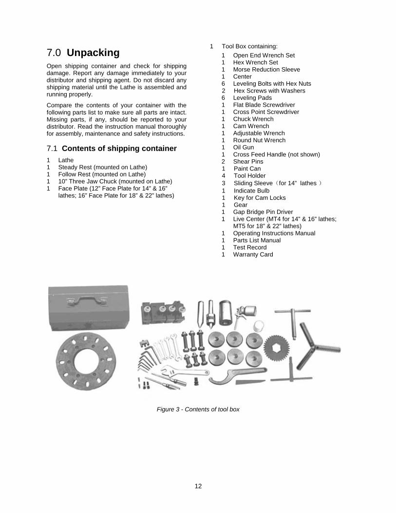
7.1 Contents of shipping container 1 Lathe 1 Steady Rest (mounted on Lathe) 1 Follow Rest (mounted on Lathe) 1 10” Three Jaw Chuck (mounted on Lathe) 1 Face Plate (12” Face Plate for 14” & 16”
lathes; 16” Face Plate for 18” & 22” lathes)
1 Tool Box containing: 1 Open End Wrench Set 1 Hex Wrench Set 1 Morse Reduction Sleeve 1 Center 6 Leveling Bolts with Hex Nuts 2 Hex Screws with Washers 6 Leveling Pads 1 Flat Blade Screwdriver 1 Cross Point Screwdriver 1 Chuck Wrench 1 Cam Wrench 1 Adjustable Wrench 1 Round Nut Wrench 1 Oil Gun 1 Cross Feed Handle (not shown) 2 Shear Pins 1 Paint Can 4 Tool Holder 3 Sliding Sleeve(for 14” lathes ) 1 Indicate Bulb 1 Key for Cam Locks 1 Gear 1 Gap Bridge Pin Driver 1 Live Center (MT4 for 14” & 16” lathes;
MT5 for 18” & 22” lathes) 1 Operating Instructions Manual 1 Parts List Manual 1 Test Record 1 Warranty Card
Figure 3 - Contents of tool box

13
Read and understand the entire contents of this
manual before attempting set-up or operation! Failure to comply may cause serious injury.
8.0 Installation 1. Finish removing all crate material from around
the lathe.
2. Unbolt lathe from shipping pallet.
3. Choose a location for the lathe that is dry and has sufficient illumination (consult OSHA or ANSI standards for recommended lighting levels in workshop environments).
4. Allow enough room to service the lathe on all four sides, and to load and off-load work pieces. In addition, if bar work is to be performed, allow enough space for stock to extend out the headstock end. If used in production operations, leave enough space for stacking unfinished and finished parts.
5. The foundation must be solid to support the weight of the machine and prevent vibration, preferably a solid concrete floor.
6. Sling the lathe as shown in Figure 4; either below the bed at center of gravity area, or around steel rods or pipes of sufficient strength inserted through the holes in the bed casting. Do not lift lathe by the spindle. With adequate lifting equipment, slowly raise the lathe off the shipping pallet. Make sure lathe is balanced before moving.
Figure 4: Lifting the lathe
Confirm that all suspension equipment is properly rated and in good condition for lifting lathe. Do not allow anyone beneath or near load while lifting.
7. The lathe can be placed upon the cast iron leveling pads under each foot hole, and adjusted using the adjusting bolts with hex nuts. Or, it may be secured to the floor using bolts placed head-down in the concrete, and using shims where needed to level the machine. Refer to Figure 1 for mounting hole dimensions.
8.1 Leveling the lathe It is imperative that the lathe be on a level plane; that is, where headstock and tailstock center points remain aligned throughout the tailstock travel, with the bed ways absent of twist and thus parallel to the operational center line.
A lathe which is not properly leveled will be inaccurate, producing tapered cuts. Also, the center point of the tailstock will vary as it is positioned along the bed, thus requiring constant readjustment of the set of the tailstock.
8. Use a machinist’s precision level on the bed ways both front to back and side to side, as shown in Figure 5. Take the reading in one direction every ten inches. Make sure the ways are clean and free of any debris before placing a level upon them.
9. Deviation over bed length (see Figure 5):
a) Maximum 0.02/1000mm
b) Maximum 0.04/1000mm
Figure 5: Leveling
10. Tighten foot screw nuts evenly to avoid distortion.
11. Leveling should be inspected occasionally, and especially if the accuracy of the lathe begins to diminish.
8.2 Completing installation 12. Clean all rust protected surfaces using a mild
commercial solvent, kerosene or diesel fuel. Do not use paint thinner, gasoline, or lacquer thinner. These will damage painted surfaces. Cover all cleaned surfaces with a light film of 20W machine oil.
13. Open the end gear cover. Clean all components of the end gear assembly and coat all gears with a heavy, non-slinging grease. Close the end gear cover.

14
8.3 Chuck preparation (three-jaw)
Read and understand all directions for chuck preparation. Failure to comply may cause serious personal injury and/or damage to the lathe.
The three-jaw scroll chuck is shipped pre-installed on the lathe. It can be used for clamping cylindrical, triangular and hexagonal stock, and has reversible jaws.
Note: An optional 12-inch, 4-jaw chuck is available (part no. ZX-OP-2A). See your dealer to order.
Before removing a chuck, place a flat piece of thick plywood across the bedways under the chuck to prevent damage to the bedways should the chuck fall from your hands. Alternatively, many users make a wood chuck cradle that sits atop the ways and accepts the specific diameter of chuck, for easier installing and removal. Figure 6 shows an example.
Figure 6: Chuck cradle
To remove the chuck:
1. Support the chuck while turning six camlocks 1/4 turn counterclockwise with the chuck wrench from the tool box.
2. Carefully remove the chuck from the spindle and place on an adequate work surface.
3. Inspect the camlock studs. Make sure they have not become cracked or broken during transit. Clean all parts thoroughly with solvent. Also clean the spindle and camlocks.
4. Cover all chuck jaws and scroll inside the chuck with #2 lithium tube grease. Cover the spindle, camlocks, and chuck body with a light film of 20W oil.
5. Lift the chuck up to the spindle nose and press onto the spindle. Tighten in place by turning the camlocks 1/4 turn clockwise. The index mark (A, Figure 7) on the camlock should be between the two indicator arrows (B) when tight, as shown in Figure 7.
• If the index mark (A) is not between the two arrows, i.e. the cam turns beyond the indicator arrows, then remove the chuck and turn the camlock stud IN one full turn.
• If a camlock will not engage, remove the chuck and turn the camlock stud OUT one full turn.
Figure 7: Camlock
6. Make sure chuck is secure on the spindle with the camlocks correctly engaged.
8.4 Break-in period Do not run the lathe above 560 RPM for the first six hours of operation, to allow gears and bearings to adapt and run smoothly.

15
9.0 Maintenance/Lubrication Lathe must be serviced at all
lubrication points and all reservoirs filled to operating level before the lathe is put into service. Failure to comply may cause serious damage to the lathe.
The ZX series lathe is shipped with oil in the reservoirs. Coolant is not included.
Use clean lubricants and check levels often, including before each working shift. To ensure proper lubrication, oil levels should not be less than the center of the oil sight glass. Try not to overfill, as this may cause leakage.
A chart is supplied in section 15.0 for quick reference to all lubrication points.
Unless specified otherwise, the lubrication points require a non-detergent, ISO 68, SAE 20W oil. The recommended brand for this lathe is Mobil DTE® Oil Heavy Medium.
1. Headstock – Oil must be up to indicator mark in oil sight glass (A, Figure 9). Top off with SAE 20W. Fill by removing the plug on top of the headstock. To drain, remove drain plug on the left side of the headstock at the lower rear corner. Drain oil completely and clean out all metal shavings. Refill after the first month of operation. Then change the oil in the headstock every two months.
2. Gearbox – Oil must be up to indicator mark in oil sight glass (B, Figure 9). Top off with SAE 20W. To add oil to the gearbox, remove two screws on the top cover and remove cover. To drain, remove drain plug (C, Figure 9) on the left side of the gearbox. Drain oil completely and refill after the first three months of operation. Then change oil in the gearbox every six months.
Figure 9
3. Apron – Oil must be between indicator marks in the oil sight glass (A, Figure 10). Top off with SAE 20W. Remove oil plug (B, Figure 10) to fill. To drain, remove drain plug on bottom of apron.
Drain oil completely and refill after the first three months of operation. Then, change oil in the apron annually. Pull knob (C, Figure 10) on the one-shot lube system and hold for several seconds to allow oil to fill the pump. When the knob is released, oil will flow through various oil lines to lubricate the ways and cross slide surface. Perform this twice daily or as needed. When the oil level is below the indicator mark, oil must be added.
Figure 10
4. Leadscrew and Feed Rod – Daily lubricate two ball oilers on the right side bracket (A, Figure 11) with SAE 20W once or twice per shift.

16
Figure 11
Saddle – Daily lubricate ball oiler (A, Figure 12) on handwheel shaft with SAE 20W.
The anti-dust felt on both ends of the saddle where it contacts the ways should be cleaned weekly with kerosene. If the felt becomes damaged, replace it.
5. Compound Rest – Daily lubricate two ball oilers (B, Figure 12) on top of compound rest with SAE 20W.
6. Cross Slide – Daily lubricate one ball oiler (C, Figure 12 – opposite side) with SAE 20W.
Figure 12
7. Tailstock – Daily lubricate one ball oiler (A, Figure 13) on top of tailstock with SAE 20W.
Figure 13
8. V-Belts – Regularly check and adjust the tightness of the v-belts to prolong their service life. See section 14.6, Belt replacement and adjustment.
10.0 Coolant preparation Follow coolant manufacturer’s
recommendations for use, care and disposal.
1. Remove access cover on tailstock end at the rear base of the lathe. Make sure coolant pump has not shifted during transport.
2. Pour four gallons (approximate) of coolant mix into the chip pan.
3. After machine has been connected to power, turn on coolant pump and check to see that coolant is cycling properly.
4. Replace access cover.
11.0 Electrical connections Electrical connections must be
made by a qualified electrician in compliance with all relevant codes. This machine must be properly grounded while in use to help protect the operator from electrical shock and possible fatal injury.
The main motor is rated at 7-1/2 HP (or 10HP for model 2280ZX), 230/460V and comes from the factory prewired at 230V. Confirm that power available at the lathe’s location is the same rating as the lathe.
Power is connected properly when rotation of the forward-reverse knob (see E, Figure 15) to the left position causes the spindle to rotate counterclockwise as viewed from the tailstock. If the chuck rotates in the clockwise direction, disconnect the lathe from the power source, switch any two of the three power leads (not the green ground wire), and re-connect the lathe to the power source.

17
11.1 Conversion to 460 volt operation
Disconnect machine from power source. Failure to do so may cause serious injury.
Main Motor: Change the wires according to the diagram on the outside of the motor junction box.
Transformer: Open electrical panel on rear of machine on the headstock side. Switch wire from 230V terminal to 460V terminal as outlined on the transformer.
Coolant Pump: Open access panel on the base at the tailstock end. Change wires in coolant pump junction box according to diagram on the outside of the junction box cover.
Main Power Switch (A, Figure 14): Turns power to machine on and off.
Power Source Cable Receiver (B, Figure 14).
Make sure the lathe is properly grounded.
Figure 14: Power input
12.0 Controls
Figure 15 – Headstock controls
1. Control Panel: located on front of headstock.
• Coolant On-Off Switch (A, Figure 15) turns coolant pump on and off.
• Power Indicator Light (D, Figure 15) is lit whenever lathe is receiving power.
• Emergency Stop Switch (C, Figure 15) stops all machine functions (Caution: Lathe will still have power). Twist clockwise to re-set.
• Jog Switch (B, Figure 15). Quickly press and release to rotate the spindle.
2. Headstock Gear Change Levers (F, Figure 15): Move levers left or right to desired spindle speed, according to accompanying chart.
3. Leadscrew/Feed Rod Directional Dial (E, Figure 15): Changing knob changes direction of feed.
Do not move knob (E) while machine is running.
4. Feed/Lead Selector Levers (G, Figure 15): Used conjunctively to set up for threading or feeding, according to the accompanying chart (G1, Figure 15).

18
Figure 16 – Carriage controls and settings
5. Carriage Handwheel (H, Figure 16): Located on apron assembly. Rotate handwheel clockwise to move carriage toward tailstock (right). Rotate handwheel counterclockwise to move carriage toward headstock (left).
6. Feed Engagement Lever (J, Figure 16): Located on front of apron assembly. Pull lever up to engage. Push lever down to disengage.
7. Adjustable Feed Clutch (K, Figure 16): When the machine is overloaded, it can slip. Then cutting rate must be reduced. Note: This setting has been calibrated at the factory and should not need adjustment. If adjustment ever becomes necessary, follow the diagram on the front of the apron.
8. Longitudinal/Cross Feed Selector Lever (L, Figure 16): Can be pushed to upper, middle and lower three positions. Push the lever up, cross feed is effected. Push the lever down, longitudinal feed is effected. When the lever is in the middle position, screws can be cut by engaging the half nut.
9. Half Nut Lever (M, Figure 16): Located on front of apron assembly. Used for threading.
10. Spindle Direction Control Lever (N, Figure 16). Move lever to the right so that its tab clears the notch, then downward for forward spindle rotation, or upward for reverse spindle rotation. Allow spindle to come to a stop before changing directions. Position lever in neutral position (tab in notch) before shutting off the lathe.
11. Cross Slide Handwheel (P, Figure 16): Located above the apron assembly. Clockwise rotation moves cross slide toward rear of machine.
12. Cross Slide Lock (Q, Figure 16): Lever located on left side of cross slide. Turn clockwise to lock and counterclockwise to unlock.
13. Carriage Lock (R, Figure 16): Located on top right of carriage. Turn clockwise to lock, counterclockwise to unlock.
Carriage lock must be loose before moving carriage or damage to lathe may occur.
14. Compound Rest (S, Figure 16) is located on top of cross slide and can be rotated 360°. There are calibrations in degrees (T, Figure 16) below the rest to assist in placement of the compound rest to the desired angle.
15. Compound Rest Handle (U, Figure 16): Located on end of compound slide. Rotate clockwise or counterclockwise to position.
16. Compound Lock (not shown): Lever located on back of compound rest. Turn clockwise to lock and counterclockwise to unlock.
17. Tool Post Clamping Lever (V, Figure 16): Located on top of tool post. Rotate counter-clockwise to loosen and clockwise to tighten.
18. Thread Chaser (W, Figure 16): Indicates the point on the leadscrew where the half nut can be re-engaged to continue inch threading.
19. Tailstock Quill Clamping Lever (A, Figure 17): Located on the tailstock. Rotate clockwise to lock the sleeve. Rotate counterclockwise to unlock.
Figure 17 – Tailstock controls
20. Tailstock Clamping Lever (B, Figure 17): Lift up to lock. Push down to unlock. If the tailstock has a heavy load, tighten the hexagon head at right side of tailstock for auxiliary locking.
21. Tailstock Quill Handwheel (C, Figure 17): Rotate clockwise to advance quill and counterclockwise to retract it.

19
22. Tailstock Off-Set Adjustment (D, Figure 17): Two hex socket cap screws located on the tailstock base are used to off-set the tailstock for cutting tapers. Loosening one screw while tightening the other will off-set the tailstock. Do not clamp the tailstock lock handle when adjusting.
Figure 18 – Other controls
23. Foot Brake (A, Figure 18): The connecting rod mechanism is in the bed stand. The braking device is in the pulley of the headstock. Press the pedal to stop all lathe functions. (Caution: Lathe still has power.)
24. Micro Carriage Stop (B, Figure 18): can be used during manual feed operation. The dial can be turned for fine tuning the position of the stop. The micro carriage stop can be moved along the bed by loosening the two socket head cap screws underneath the stop.
25. Bed Cover (C, Figure 18): can be easily removed to clean out the stand.
13.0 Operation The operator should consult shop manuals such as “Machinery’s Handbook” for cutting speeds and feeds appropriate to specific workpieces. Correct feed depends upon material to be cut, cutting operation, tool type, chucking rigidity, depth of cut, and desired surface quality.
IMPORTANT: Allow a break-in period for the new lathe so that gears and bearings can adapt; do not run the lathe above 560 RPM for the first six hours of operation.
The following points must be observed when operating the lathe:
• Never turn any handles or levers when spindle is at high speed.
• Change spindle speed only after spindle stops. • Change feed rate only when spindle is at low
speed or is stopped.
• Never exceed maximum speed limitation of the work holding device.
• Before starting spindle, check that each handle or lever is at correct position to ensure normal engagement of gears. The spindle direction control lever should be at neutral position.
• If the brake becomes ineffective, turn off machine and adjust brake immediately.
• When operating spindle direction control lever, always turn it to correct position; never use “pre-position” for cutting at a reduced speed.
• Jaw teeth and scroll must be fully engaged, to prevent the jaws from breaking and being thrown from chuck (see Figure 19).
Figure 19 – Insufficient jaw tooth engagement
• Avoid long workpiece extensions, as parts may bend or fly off (see figure 20). Use rests or the tailstock for support.
Figure 20 – Improper setups
• Avoid short clamping contact (Figure 21, A) or clamping on a minor part diameter (Figure 21, B). Face-locate the workpiece for added support.

20
Figure 21 – Improper setups
13.1 Tool setup The cutting angle is correct when the cutting edge is in line with the center axis of workpiece. Use the point of the tailstock center as a gauge and shims under the tool to obtain correct center height.
Use a minimum of two clamping screws to secure each tool.
13.2 Feed and thread selection 1. Reference the feed and thread chart (A, Figure
22).
2. Move levers and knobs (B/C/D/E, Figure 22) to the appropriate position according to the feed and thread chart.
Figure 22
13.3 Thread cutting 1. Set forward/reverse lever (F, Figure 22) to
desired direction.
2. Set selector levers (G/H, Figure 22) to desired R.P.M.
3. Select desired thread using levers (B/C/D/E, Figure 22).
4. Set selector lever (A, Figure 23) to correct position (neutral).
5. Engage the half nut lever (B, Figure 23).
6. Make a test cut with scrap material and check results before cutting regular material.
Figure 23
14.0 Adjustments Adjustments to the lathe,
especially those involving alignments of bearings, spindle, leadscrew, clutch, etc., should only be performed by qualified personnel, as improper alignments can damage the machine and/or create a safety hazard.
Turn off main switch and press emergency stop button before making adjustments to lathe.
14.1 Chuck jaw reversal The three jaws on the scroll chuck are reversible, to hold stock with larger diameters. See Figure 24. Loosen two screws with the provided hex key, remove jaw, and rotate it 180-degrees. Re-install jaw, and tighten each screw in increments until fully tightened.

21
Figure 24 – Chuck jaw reversal
14.2 Gib adjustments After a period of time, some moving components may need adjustment for play (or “backlash”) due to wear. Do not overtighten gib screws as this can hasten wear to components.
14.2.1 Saddle Turn gib screws on either side of the saddle at the rear to adjust the drag on the saddle.
14.2.2 Cross slide Gib screws are located at front and rear of slide opposite to one another (A, Figure 25). To adjust drag, loosen rear gib screw one turn, and tighten front gib screw a quarter turn. Rotate handwheel to check play. Repeat as needed until slide moves freely without play. Gently tighten rear gib screw.
14.2.3 Compound rest Gib screws are located at front and rear of compound rest (B, Figure 25). To adjust, use same method as for Cross Slide.
Figure 25 – Gib adjustments, slide and rest
14.2.4 Half Nut Gib screws are located on right side of apron (C, Figure 26). Loosen the jam nuts and rotate the screws clockwise until any backlash is corrected. Then re-tighten nuts.
Figure 26 – Half nut gib adjustment
14.3 Tailstock off-set Follow the procedure below to off-set the tailstock to cut shallow tapers:
1. Loosen tailstock in position by lowering locking handle (B, Figure 27) and loosening hexagon head eccentric shaft at back of tailstock.
2. Alternately loosen and tighten front and rear screws (D, Figure 27). Note: Front screw is shown.
The scale on the end of the tailstock base indicates amount of offset, and helps when re-centering.
If clamping force needs to be adjusted, use the hex nut beneath the tailstock body.
Figure 27 – Tailstock offset
14.4 Removing gap bridge 1. To remove the gap bridge, remove four hex
socket cap screws, and two hex cap bolts.
2. Tighten the hex nuts on the tapered alignment pins to loosen the pins. Once loosened, they can be removed.
3. Gap bridge can now be removed.
22
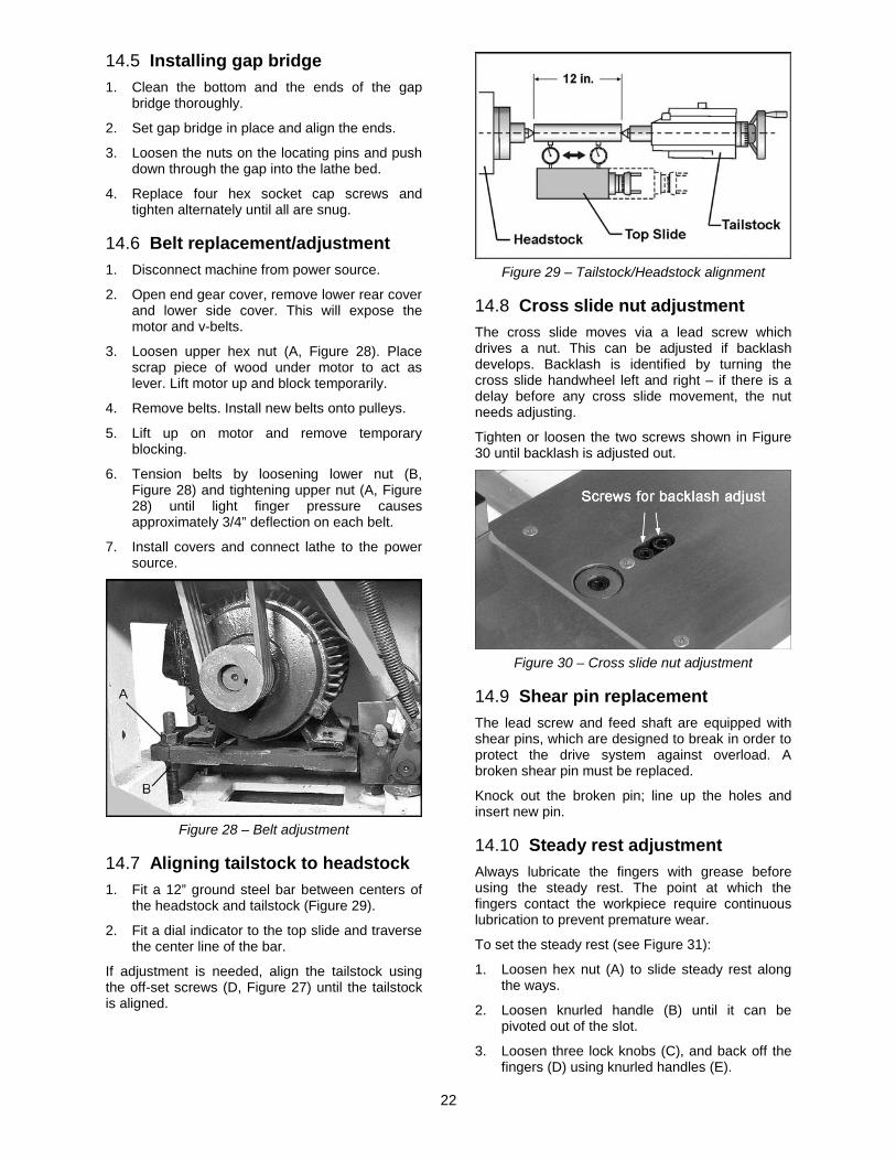
14.5 Installing gap bridge 1. Clean the bottom and the ends of the gap
bridge thoroughly.
2. Set gap bridge in place and align the ends.
3. Loosen the nuts on the locating pins and push down through the gap into the lathe bed.
4. Replace four hex socket cap screws and tighten alternately until all are snug.
14.6 Belt replacement/adjustment 1. Disconnect machine from power source.
2. Open end gear cover, remove lower rear cover and lower side cover. This will expose the motor and v-belts.
3. Loosen upper hex nut (A, Figure 28). Place scrap piece of wood under motor to act as lever. Lift motor up and block temporarily.
4. Remove belts. Install new belts onto pulleys.
5. Lift up on motor and remove temporary blocking.
6. Tension belts by loosening lower nut (B, Figure 28) and tightening upper nut (A, Figure 28) until light finger pressure causes approximately 3/4” deflection on each belt.
7. Install covers and connect lathe to the power source.
Figure 28 – Belt adjustment
14.7 Aligning tailstock to headstock 1. Fit a 12” ground steel bar between centers of
the headstock and tailstock (Figure 29).
2. Fit a dial indicator to the top slide and traverse the center line of the bar.
If adjustment is needed, align the tailstock using the off-set screws (D, Figure 27) until the tailstock is aligned.
Figure 29 – Tailstock/Headstock alignment
14.8 Cross slide nut adjustment The cross slide moves via a lead screw which drives a nut. This can be adjusted if backlash develops. Backlash is identified by turning the cross slide handwheel left and right – if there is a delay before any cross slide movement, the nut needs adjusting.
Tighten or loosen the two screws shown in Figure 30 until backlash is adjusted out.
Figure 30 – Cross slide nut adjustment
14.9 Shear pin replacement The lead screw and feed shaft are equipped with shear pins, which are designed to break in order to protect the drive system against overload. A broken shear pin must be replaced.
Knock out the broken pin; line up the holes and insert new pin.
14.10 Steady rest adjustment Always lubricate the fingers with grease before using the steady rest. The point at which the fingers contact the workpiece require continuous lubrication to prevent premature wear.
To set the steady rest (see Figure 31):
1. Loosen hex nut (A) to slide steady rest along the ways.
2. Loosen knurled handle (B) until it can be pivoted out of the slot.
3. Loosen three lock knobs (C), and back off the fingers (D) using knurled handles (E).

23
4. Pivot the collar on its hinge and position steady rest around workpiece.
5. Firmly tighten hex nut (A).
6. Set the fingers snugly to work piece and secure by tightening locking knobs. Fingers should be snug but not overly tight.
Figure 31 – Steady rest adjustment
14.11 Follow rest adjustment The follow rest mounts to the saddle with two socket head cap bolts. The follow rest should be mounted so that locking knobs point away from chuck.
The sliding fingers are set similar to those on the steady rest – free of play, but not binding.
Always lubricate the fingers sufficiently with grease before operating.
14.12 Carriage stops Adjust each stop (Figure 32) by loosening two set screws, and sliding it along the rod. Rotate the stop so that the raised area is upward to contact the carriage. Tighten both set screws securely.
Position the raised area downward when the stop is not being used.
Figure 32

24
15.0 Lubrication schedule and general maintenance Regularly scheduled maintenance is crucial to ensure a long service life for your machine. The schedule below shows general cleaning, lubrication points and coolant replacement information for the ZX Series Lathes. Push stop button and power off before lubricating. Follow local regulations for disposal of used coolant/lubricants. Minimize direct skin contact with lubricants and coolants, and wear eye protection when pouring coolant in case of splash.
Mobile DTE® Oil Heavy Medium is recommended for the SAE-20W machine oil.
If the brand of oil is ever changed, it is recommended that you flush and clean the reservoir first to prevent any compatibility issues.
Table 1
Section Element Action Lubricant Frequency
8.3 Chuck Grease jaws and scroll #2 lithium tube grease periodically
8.3 Spindle/cam locks/ chuck body
light coat of oil SAE-20W machine oil periodically
All exposed metal surfaces
light coat of oil SAE-20W machine oil frequently
9.0 Headstock Drain and fill SAE-20W machine oil - after 30 days, - every 2 months
9.0 Gearbox Drain and fill SAE-20W machine oil - after first 3 months, - every 6 months
9.0 Apron and Saddle Drain and fill SAE-20W machine oil - after first 3 months, - then annually
9.0 Leadscrew; Feed Rod; Spindle Direction Control Axle
Fill at ball oilers SAE-20W machine oil daily (1 or 2 times per shift)
Travel Setting Rod Fill at (1) ball oiler SAE-20W machine oil as needed 9.0 Cross slide Fill at (2) ball oilers SAE-20W machine oil daily 9.0 Compound rest Fill at (2) ball oilers SAE-20W machine oil daily 9.0 Tailstock Fill at (1) ball oiler SAE-20W machine oil daily 9.0 Anti-dust felt on v-ways Clean kerosene Inspect weekly
10.0 Coolant reservoir (follow coolant manufacturer’s directions)
Coolant of choice, approx. 4 gallons
(follow coolant manufacturer’s directions)
14.10 Steady Rest Lubricate finger shafts and contact points
Lead-based grease before each use
14.11 Follow Rest Lubricate finger shafts and contact points
Lead-based grease before each use
14.6 V-belts Inspect and tighten if needed
periodically

25
16.0 Reference tables 16.1 Inch Lead And Feed Table 2
F E E D I N / R E V
LONGITUDINAL TRANSVERSE
26
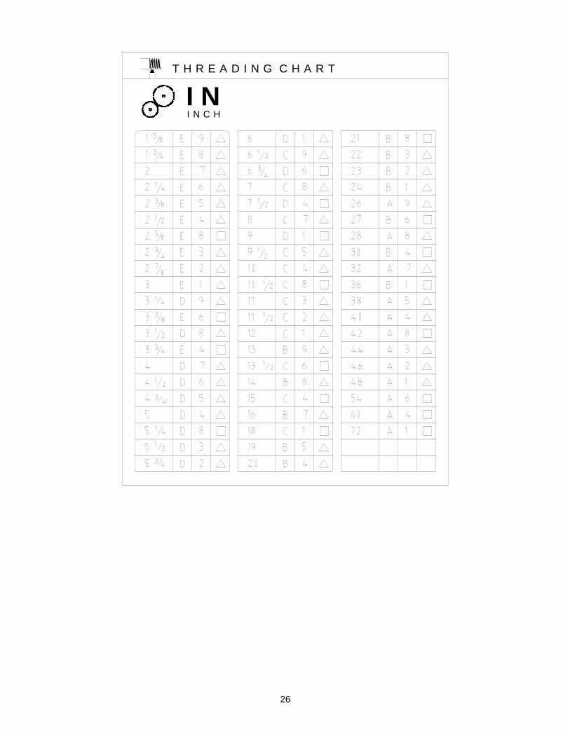
T H R E A D I N G C H A R T
I NI N C H

27
m mM E T R I C
T H R E A D I N G C H A R T
M PM O D U L E P I T C H

28
D PD I A M E T R A L P I T C H
T H R E A D I N G C H A R T
427 New Sanford Road LaVergne, Tennessee 37086
Phone: 800-274-6848 www.jettools.com

Parts List and Electrical Diagrams ZX-Series Large Bore Lathes Models GH-1440ZX
GH-1640ZX/1660ZX GH-1860ZX/1880ZX GH-2280ZX
* For ZX-Series Lathes Operating Instructions, see document M-321910
JET
427 New Sanford Road LaVergne, Tennessee 37086 Ph.: 800-274-6848
Model GH-1440ZX shown
www.jettools.com
Part No. M-321910-1Revision J 10/2017
Copyright © 2017 JET

2
Table of Contents 1.1 Stand Assembly – Exploded View ...................................................................................................... 3 1.2 Stand Assembly – Parts List ............................................................................................................... 4 2.1 Brake Assembly – Exploded View ...................................................................................................... 6 2.2 Brake Assembly – Parts List .............................................................................................................. 7 3.1 Bed Assembly – Exploded View ......................................................................................................... 8 3.2 Bed Assembly – Parts List.................................................................................................................. 9 4.1 Headstock Assembly I – Exploded View .......................................................................................... 11 4.2 Headstock Assembly I – Parts List ................................................................................................... 12 5.1 Headstock Assembly II – Exploded View ......................................................................................... 15 5.2 Headstock Assembly II – Parts List .................................................................................................. 16 6.1 Headstock Assembly III – Exploded View ........................................................................................ 18 6.2 Headstock Assembly III – Parts List ................................................................................................. 19 7.1 Headstock Assembly IV – Exploded View ........................................................................................ 20 7.2 Headstock Assembly IV – Parts List ................................................................................................ 21 8.1 Change Gear Box Assembly I – Exploded View .............................................................................. 22 8.2 Change Gear Box Assembly I – Parts List ....................................................................................... 23 9.1 Change Gear Box Assembly II – Exploded View ............................................................................. 24 9.2 Change Gear Box Assembly II – Parts List ...................................................................................... 25 10.1 Quick Change Gear Box I – Exploded View .................................................................................. 26 10.2 Quick Change Gear Box I – Parts List ........................................................................................... 27 11.1 Quick Change Gear Box II – Exploded View .................................................................................. 29 11.2 Quick Change Gear Box II – Parts List .......................................................................................... 30 12.1 Quick Change Gear Box III – Exploded View ................................................................................ 31 12.2 Quick Change Gear Box III – Parts List ......................................................................................... 32 13.1 Apron Assembly I – Exploded View ................................................................................................ 33 13.2 Apron Assembly I – Parts List ........................................................................................................ 34 14.1 Apron Assembly II – Exploded View ............................................................................................... 36 14.2 Apron Assembly II – Parts List ....................................................................................................... 37 15.1 Apron Assembly III – Exploded View .............................................................................................. 39 15.2 Apron Assembly III – Parts List ...................................................................................................... 40 16.1 Carriage Assembly – Exploded View ............................................................................................. 41 16.2 Carriage Assembly – Parts List ...................................................................................................... 42 17.1 Micro Carriage Stop – Exploded View ............................................................................................ 44 17.2 Micro Carriage Stop – Parts List .................................................................................................... 44 18.1 Carriage Stop Assembly – Exploded View ..................................................................................... 45 18.2 Carriage Stop Assembly – Parts List .............................................................................................. 46 19.1 Quick Change Tool Post – Exploded View ..................................................................................... 47 19.2 Quick Change Tool Post – Parts List .............................................................................................. 48 20.1 Tailstock Assembly I – Exploded View ........................................................................................... 49 20.2 Tailstock Assembly I – Parts List .................................................................................................... 50 21.1 Tailstock Assembly II – Exploded View .......................................................................................... 51 21.2 Tailstock Assembly II – Parts List ................................................................................................... 52 22.1 Steady Rest Assembly – Exploded View........................................................................................ 53 22.2 Steady Rest Assembly – Parts List ................................................................................................ 54 23.1 Follow Rest Assembly – Exploded View ........................................................................................ 55 23.2 Follow Rest Assembly – Parts List ................................................................................................. 56 24.1 Coolant & Work Light Assembly – Exploded View ......................................................................... 57 24.2 Coolant & Work Light Assembly – Parts List .................................................................................. 58 25.1 Other Parts ..................................................................................................................................... 59 26.1 Electrical Cabinet – Parts List ........................................................................................................ 60 26.2 Electrical Cabinet – Breakdown ..................................................................................................... 61 27.0 Wiring Diagram ............................................................................................................................... 62 28.0 Rotary Switch Diagram ................................................................................................................... 63 29.1 Safety Guard Cover – Exploded View ............................................................................................ 64 29.2 Safety Guard Cover – Parts List .................................................................................................... 64 30.1 Carriage Lubrication – Exploded View ........................................................................................... 65 30.2 Carriage Lubrication – Parts List .................................................................................................... 65
3
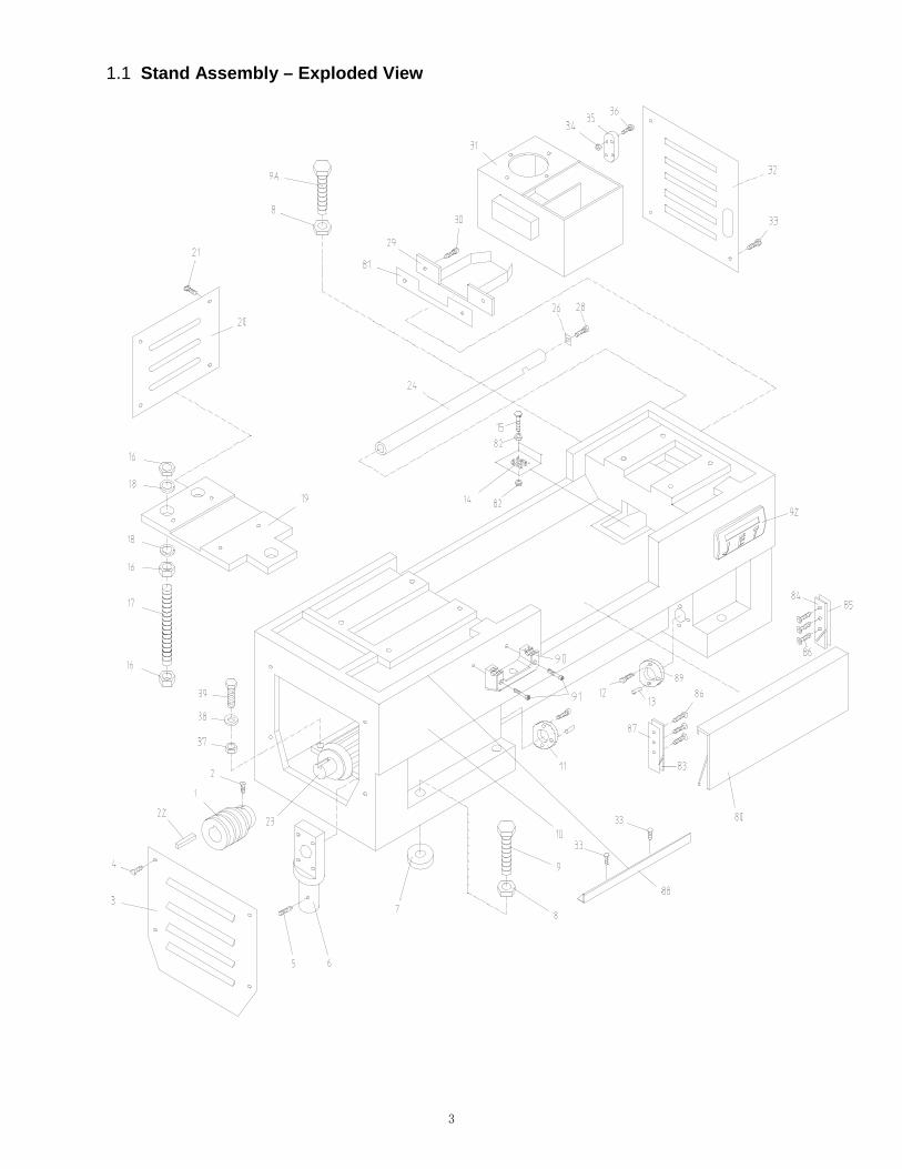
1.1 Stand Assembly – Exploded View

4
1.2 Stand Assembly – Parts List
Index No Part No Description Size Qty
1 .......... ZX-01101A .................... Pulley .................................................................. .................................... 1 ............ GH2280ZX-01101 ......... Pulley (for 2280ZX) .............................................. .................................... 1 2 .......... ZX-S2 ............................ Cylindrical End Set Screw .................................... M8x16 ......................... 1 3 .......... ZX-01734-G .................. Cover .................................................................... .................................... 1 ............ ML-2080-01701-G ......... Cover (for 2280ZX) .............................................. .................................... 1 4 .......... ZX-S4 ............................ Cross Head Screw ............................................... M6x14 ......................... 4 5 .......... ZX-S2 ............................ Cylindrical End Set Screw .................................... M8x16 ......................... 1 6 .......... ZX-01701 ...................... Pedal Rod Support ............................................... .................................... 1 ............ ML-2080-01703 ............. Pedal Rod Support (for 2280ZX) ......................... .................................... 1 7 .......... ZX-01715 ...................... Lining .................................................................... .................................... 6 8 .......... TS-1540231 .................. Hex Nut ................................................................ M24-2 .......................... 6 9 .......... ZX-01712 ...................... Hex Cap Bolt ........................................................ .................................... 3 9A ........ ZX-01713 ...................... Hex Cap Bolt ........................................................ .................................... 3 10 ........ ZX-01102A .................... Bed Stand (for 40” models, serial # 010611ZX349 and lower) ................. 1 ............ ZX-01102AN .................. New Bed Stand (for 40” models, serial # 010618ZX350 and lower) ......... 1 ............ ZX-01102AN-G .............. Bed Stand (for 40” models) .................................. .................................... 1 ............ ZX-01102B .................... Bed Stand (for 60” models, serial # 010611ZX349 and lower) ................. 1 ............ ZX-01102BN .................. New Bed Stand (for 60” models, serial # 010618ZX350 and lower)........ 1 ............ ZX-01102BN-G .............. Bed Stand (for 60” models) .................................. .................................... 1 ............ ZX-01102C .................... Bed Stand (for 1880ZX, serial # 010611ZX349 and lower) ..................... 1 ............ ZX-01102CN.................. New Bed Stand (for 1880ZX, serial # 010618ZX350 and lower) .............. 1 ............ ZX-01102CN-G ............. Bed Stand (for 1880ZX) ....................................... .................................... 1 ............ GH2280ZX-01102-G ..... Bed Stand (for 2280ZX) ....................................... .................................... 1 11 ......... ZX-01703 ...................... Fixed Support ....................................................... .................................... 1 12 ........ TS-150341 .................... Socket Head Cap Screw ...................................... M6x14 ......................... 4 13 ........ ZX-S13 .......................... Taper Pin .............................................................. 5x20 mm ..................... 2 14 ........ ZX-01705 ...................... Water Leaking Chip Guard................................... .................................... 1 15 ........ ZX-S15A ........................ Cross Head Screw ............................................... M5x20 ......................... 4 16 ........ TS-1540121 .................. Hex Nut ................................................................ M20 ............................. 9 17 ........ ZX-01702 ...................... Bolt ....................................................................... .................................... 3 ............ ML-2080-01704 ............. Bolt (for 2280ZX) .................................................. .................................... 3 18 ........ TS-1550111 ................... Flat Washer .......................................................... M20 ............................. 6 19 ........ ZX-01122A .................... Motor Mounting Plate (for 14” models) ................ .................................... 1 ............ ZX-01122B .................... Motor Mounting Plate (for 16”/18” models) .......... .................................... 1 ............ ML-2080-01122 ............. Motor Mounting Plate (for 22” model)) ................. .................................... 1 20 ........ ZX-01726-G .................. Cover .................................................................... .................................... 1 ............ GH2280ZX-01701-G ..... Cover .................................................................... .................................... 1 21 ........ ZX-S4 ............................ Cross Head Screw ............................................... M6x14 ......................... 4 22 ........ ZX-S22 .......................... Key ....................................................................... 10x8x70 mm ............... 1 23 ........ ZX-S23BC ..................... Main Motor (for 22” model) .................................. 10 HP, 6P, 3Ph ............ 1 ............ ZX-S23A ........................ Main Motor (for 14” models) ................................. 7.5HP, 4P, 3Ph ............ 1 ............ ZX-S23B ........................ Main Motor (for 16”/18” models) .......................... 7.5HP, 6P, 3Ph ............ 1 24 ........ ZX-017609A .................. Wire Conduit (for 1440/1640/1840ZX) ................. .................................... 1 ............ ZX-017609B .................. Wire Conduit (for 1460/1660/1860ZX) ................. .................................... 1 ............ ZX-017609C .................. Wire Conduit (for 1880/2280ZX) .......................... .................................... 1 26 ........ ZX-01706 ...................... Locking Plate........................................................ .................................... 1 28 ........ ZX-S15 .......................... Cross Head Screw ............................................... M4x6 ........................... 1 29 ........ ZX-01711-G ................... Water Reception Plate ......................................... .................................... 1 30 ........ ZX-S4 ............................ Cross Head Screw ............................................... M6x14 ......................... 2 31 ........ ZX-01510 ...................... Coolant Tank ........................................................ .................................... 1 32 ........ ZX-01714-G .................. Cover .................................................................... .................................... 1 ............ ML-2080-01702-G ......... Cover (for 2280ZX) .............................................. .................................... 1 33 ........ ZX-S4 ............................ Cross Head Screw ............................................... M6x14 ......................... 6 34 ........ ZX-S34 .......................... Nut ........................................................................ M3 ............................... 4 35 ........ ZX-S35 .......................... Coolant Indicator .................................................. .................................... 1 36 ........ ZX-S36 .......................... Cross Head Screw ............................................... M3x20 ......................... 4

5
Index No Part No Description Size Qty
37 ........ TS-1540072 .................. Hex Nut ................................................................ M10 ............................. 4 38 ........ TS-1550071 .................. Flat Washer .......................................................... M10 ............................. 4 39 ........ TS-1491041 .................. Hex Cap Bolt ........................................................ M10x30 ....................... 4 80 ........ ZX-01716A-G ................ Stand Front Cover (for 1440/1640/1840ZX) ........ .................................... 1 ............ ZX-01716B-G ................ Stand Front Cover (for 1460/1660/1860ZX) ........ .................................... 1 ............ ZX-01716C-G ................ Stand Front Cover (for 1880/2280ZX) ................. .................................... 1 81 ........ ZX-01501 ...................... Gasket .................................................................. .................................... 1 82 ........ ZX-S82 .......................... Hex Nut ................................................................ M5 ............................... 2 83 ........ ZX-01740 ...................... Left Tray ............................................................... .................................... 1 84 ........ ZX-01741 ...................... Right Tray ............................................................. .................................... 1 85 ........ ZX-01511 ....................... Gasket .................................................................. .................................... 2 86 ........ ZX-S86 .......................... Cross Head Screw ............................................... M5x16 ......................... 6 87 ........ ZX-01512 ...................... Gasket .................................................................. .................................... 1 88 ........ ZX-05753-G .................. Extending Plate .................................................... .................................... 1 89 ........ ZX-01703A .................... Fixed Support(serial # 070916ZX1738 and higher) .......................... .. 1 90 ....... 1440R09302A ................ Chuck Key Holder (serial # 160410ZX3032 and higher) .......................... 1 91 ....... GB70- M8x50 ................ Hex Socket Cap Screw (serial # 160410ZX3032 and higher) .................... ........... ....................................... ............................................................................ M8x50 .......................... 2 92 ....... JET-165 ......................... JET Logo ............................................................. ..................................... 1 93 ........ JX21004-G .................... Terminal Board (not shown) ................................. .................................... 1 94 ........ 18301-G ........................ Junction Box (not shown) ..................................... .................................... 1 95 ........ D97-4-G ........................ Plastic Fitting (not shown) .................................... .................................... 1 96 ........ ZX-S96 .......................... Proximity Switch for Chuck Key Holder (not shown) ................................ 1

6
2.1 Brake Assembly – Exploded View

7
2.2 Brake Assembly – Parts List
Index No Part No Description Size Qty
40 ........ ZX-22101-G .................. Fork ...................................................................... .................................... 1 41 ........ ZX-S41 .......................... Spring Pin ............................................................. 8x40 mm ..................... 1 42 ........ ZX-22703 ...................... Butt Nail Support .................................................. .................................... 1 43 ........ TS-1524021 .................. Socket Set Screw ................................................. M8x10 ......................... 1 44 ........ ZX-S44 .......................... Cross Head Screw ............................................... M5x20 ......................... 4 45 ........ ZX-22714 ...................... Positioning Plate .................................................. .................................... 1 46 ........ ZX-22704A .................... Driving Shaft-Longer ............................................ .................................... 1 48 ........ ZX-S48 .......................... Spring Pin ............................................................. 5x30 mm ..................... 2 49 ........ ZX-22712A .................... Pedal (for 1440/1640/1840ZX,serial # 070820ZX1737 and lower) ........ 1 ............ ZX-22712AE .................. Pedal (for 1440/1640/1840ZX,serial # 070916ZX1738 and higher) ...... 1 ............ ZX-22712B .................... Pedal (for 1460/1660/1860ZX,serial # 070820ZX1737 and lower) ........ 1 ............ ZX-22712BE .................. Pedal (for 1460/1660/1860ZX,serial # 070916ZX1738 and higher) ...... 1 ............ ZX-22712C .................... Pedal (for 1880/2280ZX,serial # 070820ZX1737 and lower) ................. 1 ............ ZX-22712CE ................. Pedal (for 1880/2280ZX,serial # 070916ZX1738 and higher) ............... 1 50 ........ ZX-22710A-G ................ Draw Bar (for 14” models) .................................... .................................... 1 ............ ZX-22710B-G ................ Draw Bar (for 16” models) .................................... .................................... 1 ............ ZX-22710C-G ................ Draw Bar (for 18” models) .................................... .................................... 1 ............ GH2280ZX-22710-G ..... Draw Bar (for 22” model) ..................................... .................................... 1 51 ........ ZX-22706 ...................... Connecting Shaft.................................................. .................................... 1 52 ........ ZX-S52 .......................... Split Pin ................................................................ 2x20 mm ..................... 2 53 ........ ZX-S53 .......................... Tensile Spring ....................................................... 3.5x26x190 mm .......... 1 54 ........ ZX-S54 .......................... Eyebolt ................................................................. M8 ............................... 1 55 ........ TS-1490091 .................. Hex Cap Bolt ........................................................ M8x50 ......................... 1 56 ........ TS-1540061 .................. Hex Nut ................................................................ M8 ............................... 1 57 ........ ZX-22707A .................... Butt Rod Support ................................................. .................................... 1 58 ........ TS-1540072 .................. Hex Nut ................................................................ M10 ............................. 1 59 ........ ZX-S59 .......................... C-Clip ................................................................... 8 mm ........................... 1 60 ........ ZX-22701 ...................... Positioning Shaft .................................................. .................................... 1 61 ........ ZX-S61 .......................... Brake Shoe .......................................................... .................................... 1 62 ........ ZX-22702 ...................... Brake Shaft .......................................................... .................................... 1 63 ........ ZX-22708 ...................... Connecting Plate .................................................. .................................... 1 64 ........ ZX-S64 .......................... Elastic Pin ............................................................ 5x25 mm ..................... 1 65 ........ ZX-22709 ...................... Connecting Shaft.................................................. .................................... 1 66 ........ ZX-S66 .......................... Stroke Switch ....................................................... .................................... 1 67 ........ ZX-S67 .......................... Screw ................................................................... M4x25 ......................... 2 68 ........ ZX-S68 .......................... Cylindrical End Set Screw .................................... M5x10 ......................... 1 69 ........ ZX-22711 ....................... Butt Nail Support .................................................. .................................... 1 70 ........ ZX-S70 .......................... Pin ........................................................................ 5n6x20 ........................ 1 71 ........ ZX-22715 ...................... Adjust Bolt ............................................................ .................................... 1 72 ........ TS-1540061 .................. Hex Nut ................................................................ M8 ............................... 1 73 ........ ZX-S73 .......................... C-Clip ................................................................... 12 mm ......................... 2 74 ........ TS-149006 .................... Hex Cap Screw .................................................... M8x35 ......................... 1

8
3.1 Bed Assembly – Exploded View

9
3.2 Bed Assembly – Parts List
Index No Part No Description Size Qty
1 .......... ZX-01104A-G ................ Bed (for 1440/1640/1840ZX) ............................... .................................... 1 ............ ZX-01104B-G ................ Bed (for 1460/1660/1860ZX) ............................... .................................... 1 ............ ZX-01104C-G ................ Bed (for 1880/2280ZX) ........................................ .................................... 1 2 .......... TS-1550101 .................. Flat Washer .......................................................... M16 ............................. 8 3 .......... ZX-B3 ............................ Hex Cap Bolt ........................................................ M16x50 ....................... 8 4 .......... ZX-01706 ...................... Rack ..................................................................... .................................... 1 5 .......... TS-1505051 .................. Hex Socket Cap Screw (for 1440/1640/1840ZX). M10x35 ..................... 10 ............ ...................................... Hex Socket Cap Screw (for 1460/1660/1860ZX). M10x35 ..................... 14 ............ ...................................... Hex Socket Cap Screw (for 1880/2280ZX) .......... M10x35 ..................... 18 6 .......... ZX-B6 ............................ Taper Pin (for 1440/1640/1840ZX) ...................... 8x50 mm ................... 10 ............ ...................................... Taper Pin (for 1460/1660/1860ZX) ...................... 8x50 mm ................... 14 ............ ...................................... Taper Pin (for 1880/2280ZX) ................................ 8x50 mm ................... 18 7 .......... ZX-01706A .................... Rack (for 1440/1640/1840ZX) .............................. .................................... 4 ............ ...................................... Rack (for 1460/1660/1860ZX) .............................. .................................... 6 ............ ...................................... Rack (for 1880/2280ZX) ....................................... .................................... 8 8 .......... ZX-01112-G ................... Saddle .................................................................. .................................... 1 9 .......... TS-1551081 .................. Lock Washer ........................................................ M12 ............................. 4 10 ........ TS-1506091 .................. Hex Socket Cap Screw ........................................ M12x55 ....................... 4 12 ........ ZX-B12 .......................... Thread Taper Pin.................................................. 12x70 mm ................... 2 13 ........ TS-1491101 ................... Hex Cap Bolt ........................................................ M10x55 ....................... 2 14 ........ TS-1550071 .................. Washer ................................................................. M10 ............................. 2 15 ........ TS-1503021 .................. Hex Socket Cap Screw ........................................ M8x12 ......................... 5 16 ........ TS-1550041 .................. Washer ................................................................. M8 ............................... 5 17 ........ ZX-01741A-G ................ Splash Guard (for 1440ZX) .................................. .................................... 1 ............ ZX-01741B-G ................ Splash Guard (for 1460ZX) .................................. .................................... 1 ............ ZX-01741C-G ................ Splash Guard (for 1640ZX) .................................. .................................... 1 ............ ZX-01741D-G ................ Splash Guard (for 1660ZX) .................................. .................................... 1 ............ ZX-01741E-G ................ Splash Guard (for 1840ZX) .................................. .................................... 1 ............ ZX-01741F-G ................ Splash Guard (for 1860ZX) .................................. .................................... 1 ............ ZX-01741G-G ................ Splash Guard (for 1880ZX) .................................. .................................... 1 ............ GH2280ZX-12701-G ..... Splash Guard (for 2280ZX) .................................. .................................... 1 18 ........ ZX-B18 .......................... Shear Pin ............................................................. 5x35 mm ..................... 2 19 ........ ZX-01708A .................... Lead Screw (for 40” models, serial # 010611ZX349 and lower) ............... 1 ............ ZX-01708AN ................. New Lead Screw (for 40” models, serial # 010618ZX350 and higher) ..... 1 ............ ZX-01708B .................... Lead Screw (for 60” models, serial # 010611ZX349 and lower) ............... 1 ............ ZX-01708BN ................. New Lead Screw (for 60” models, serial # 010618ZX350 and higher) ..... 1 ............ ZX-01708C .................... Lead Screw (for 80" models, serial #010611ZX349 and lower) ................ 1 ............ ZX-01708CN ................. New Lead Screw (for 80" models, serial #010618ZX350 and higher) ...... 1 20 ........ ZX-B20 .......................... Flat End Set Screw .............................................. M6x10 ......................... 2 21 ........ ZX-01109 ....................... Sleeve (serial # 010611ZX349 and lower) ........... .................................... 1 ............ ZX-01109N .................... New Sleeve (serial # 010618ZX350 and higher) . .................................... 1 22 ........ ZX-1204 ........................ Double Row Spherical Ball Bearing ..................... 20x47x14 .................... 2 23 ........ ZX-B23 .......................... C-Clip ................................................................... 20 mm ......................... 2 24 ....... ZX-01110 ....................... Bracket (serial # 010611ZX349 and lower) .......... .................................... 1 ............ ZX-01110N-G ................ New Bracket (serial # 010618ZX350 and higher) .................................... 1 25 ........ ZX-01111-G ................... Cover .................................................................... .................................... 1 26 ........ TS-1503041 .................. Hex Socket Cap Screw ........................................ M6x16 ......................... 4 27 ........ ZX-B27 .......................... Taper Pin .............................................................. 6x60 mm ..................... 1 28 ........ TS-1505081 .................. Socket Cap Screw ............................................... M10x50 ....................... 1 29 ........ ZX-B29 .......................... Oil Cup ................................................................. 10 mm ......................... 2 30 ........ GH2280ZX-1230 ........... Socket Cap Screw ............................................... M10x100 ..................... 1 31 ........ ZX-B31 .......................... Taper Pin .............................................................. 6x100 mm ................... 1 32 ........ ZX-01108 ....................... Sleeve (serial # 010611ZX349 and lower) ........... .................................... 1 ............ ZX-01108N .................... New Sleeve (serial # 010618ZX350 and higher) . .................................... 1 33 ........ ZX-01709A .................... Feed Rod (for 40” models, serial # 010611ZX349 and lower) .................. 1 ............ ZX-01709AN ................. New Feed Rod (for 40” models, serial # 010618ZX350 and higher) ........ 1 ............ ZX-01709B .................... Feed Rod (for 60” models, serial # 010611ZX349 and lower) .................. 1

10
Index No Part No Description Size Qty
............ ZX-01709BN ................. New Feed Rod (for 60” models, serial # 010618ZX350 and higher) ........ 1 ............ ZX-01709C .................... Feed Rod (for 80" models, serial # 010611ZX349 and lower) .................. 1 ............ ZX-01709CN ................. New Feed Rod (for 80" models, serial # 010618ZX350 and higher) ........ 1 34 ........ ZX-B34 .......................... Taper Pin .............................................................. 5x30 mm ..................... 1 35 ........ ZX-01107-G ................... Poking Block ........................................................ .................................... 1 36 ........ ZX-01707A .................... Control Rod (for 1440/1640/1840ZX) .................. .................................... 1 ............ ZX-01707B .................... Control Rod (for 1460/1660/1860ZX) .................. .................................... 1 ............ ZX-01707C .................... Control Rod (for 1880/2280ZX)............................ .................................... 1 37 ........ TS-1540031 .................. Nut ........................................................................ M5 ............................... 1 38 ........ ZX-06720 ...................... Small Shaft ........................................................... .................................... 2 39 ........ ZX-06001C-3 ................. Sleeve .................................................................. .................................... 1 40 ........ ZX-06001C-2 ................. Spacer .................................................................. .................................... 1 41 ........ ZX-B41 .......................... Spring ................................................................... 1x75x25 mm ............... 3 42 ........ ZX-06001C-1-G ............. Bracket ................................................................. .................................... 1 43 ........ TS-1504031 .................. Hex Socket Cap Screw ........................................ M8x16 ......................... 2 44 ........ ZX-B44 .......................... Lever .................................................................... .................................... 1 45 ........ ZX-06001C-4 ................. Long Lever Sleeve ............................................... .................................... 1 46 ........ ZX-B46 .......................... Hex Nut ................................................................ M8 ............................... 2 47 ........ ZX-B47 .......................... Set Screw ............................................................. M8x28 ......................... 2 48 ........ ZX-06001C-5 ................. Direction Change Ring ......................................... .................................... 1 49 ........ ZX-B49 .......................... Pin ........................................................................ 8n6x20 ........................ 1 50 ........ ZX-B50 .......................... Taper Pin .............................................................. 3x20 mm ..................... 1 51 ........ TS-1505081 .................. Socket Cap Screw ............................................... M10x50 ....................... 2 52 ........ ZX-05741 ...................... Threaded Tube ..................................................... .................................... 2 53 ........ TS-1540081 .................. Hex Nut ................................................................ M12 ............................. 2 54 ........ ZX-B54 .......................... Drum Switch ......................................................... .................................... 1 55 ........ ZX-S27 .......................... Cross Head Screw ............................................... M5x8 ........................... 5 56 ........ ZX-01718 ...................... Rocker .................................................................. .................................... 1 57 ........ ZX-B57 .......................... Pin ........................................................................ 3x16 mm ..................... 1 58 ........ ZX-01716-G .................. Bracket ................................................................. .................................... 1 59 ........ ZX-01715C-G ................ Cover .................................................................... .................................... 1 60 ........ ZX-B60 .......................... Cross Recessed Pan Head Screw ...................... M6x18 ......................... 4 61 ........ TS-1482031 .................. Hex Cap Bolt ........................................................ M6x16 ......................... 2 62 ........ ZX-B62 .......................... Pin ........................................................................ 2x15 mm ..................... 2 63 ........ ZX-01719-G .................. Rocker .................................................................. .................................... 1 64 ........ ZX-LRG14 ..................... Rubber Washer (for 14” models) ......................... .................................... 1 ............ ZX-LRG16 ..................... Rubber Washer (for 16” models) ......................... .................................... 1 ............ ZX-LRG18 ..................... Rubber Washer (for 18” models) ......................... .................................... 1 ............ ZX-LRG22 ..................... Rubber Washer (for 22” models) ......................... .................................... 1 65 ........ ZX-RRG......................... Rubber Washer .................................................... .................................... 1 66 ........ 1440R~1880R-01305 .... Plate (serial # 160401ZX3031 and lower) ........... .................................... 1 ............ 1440R~1880R-01305-5 Plate (serial # 160410ZX3032 and higher) .......... .................................... 1 67 ........ GB827-2x3 .................... Rivet ..................................................................... 2x3 mm ....................... 4

11
4.1 Headstock Assembly I – Exploded View

12
4.2 Headstock Assembly I – Parts List
Index No Part No Description Size Qty
1 .......... ZX-02306 ...................... Round Sign Plate (serial # 160401ZX3031 and lower) ............................ 1 ............ C6136ZK-02304-1 ......... Round Sign Plate (serial # 160410ZX3032 and higher) ........................... 1 1a ....... ZX-02306 ...................... Round Sign Plate (serial # 160401ZX3031 and lower) ............................ 2 ............ 14~18R-02303-2 ........... Round Sign Plate (serial # 160410ZX3032 and higher) ........................... 2 2 .......... ZX-02122-G .................. Positioning Handle ............................................... .................................... 1 3 .......... ZX-H3 ............................ Flat End Set Screw .............................................. M10x12 ....................... 1 4 .......... ZX-H4 ............................ Spring ................................................................... YI-1x8x25 .................... 1 5 .......... ZX-H5 ............................ Steel Ball .............................................................. 8 mm ........................... 1 6 .......... ZX-H6 ............................ Countersunk Head Screw .................................... M5x12 ......................... 2 7 .......... ZX-02743-G .................. Positioning Disc ................................................... .................................... 1 8 .......... ZX-02738 ...................... Shaft ..................................................................... .................................... 1 9 .......... ZX-H9 ............................ Taper Pin .............................................................. 5x55 mm ..................... 1 10 ........ ZX-H10 .......................... Woodruff Key ....................................................... 4x16 mm ..................... 1 11 ......... ZX-H11 .......................... Ring Seal .............................................................. 25x2.4 mm .................. 1 12 ........ ZX-02116 ....................... Crank .................................................................... .................................... 1 13 ........ TS-1523051 .................. Set Screw ............................................................. M6x16 ......................... 1 14 ........ ZX-H14 .......................... Pin ........................................................................ 5n6x28 ........................ 1 15 ........ ZX-02302 ...................... Poking Block ........................................................ .................................... 1 16 ........ ZX-02738C .................... Pin Block .............................................................. .................................... 1 17 ........ TS-1523051 .................. Set Screw ............................................................. M6x16 ......................... 1 18 ........ ZX-02114 ....................... Crank .................................................................... .................................... 1 19 ........ ZX-H11 .......................... Ring Seal .............................................................. 25x2.4 mm .................. 1 20 ........ ZX-H20 .......................... Pin ........................................................................ 5x30 mm ..................... 1 21 ........ ZX-02734 ...................... Shaft ..................................................................... .................................... 1 22 ........ ZX-H10 .......................... Woodruff Key ....................................................... 4x16 mm ..................... 1 23 ........ ZX-H5 ............................ Steel Ball .............................................................. 8 .................................. 1 24 ........ ZX-H4 ............................ Spring ................................................................... YI-1x8x25 .................... 1 25 ........ ZX-H3 ............................ Flat End Set Screw .............................................. M10x12 ....................... 1 26 ........ ZX-02733-G .................. Left Positioning Disc ............................................ .................................... 1 27 ........ ZX-H6 ............................ Countersunk Head Screw .................................... M5x12 ......................... 2 28 ........ ZX-02113-G ................... Left Lever Support................................................ .................................... 1 29 ........ ZX-02741 ...................... Handle .................................................................. .................................... 2 30 ........ ZX-02732 ...................... Cover .................................................................... .................................... 2 31 ........ ZX-H6 ............................ Countersunk Head Screw .................................... M5x12 ......................... 1 32 ........ ZX-H6 ............................ Countersunk Head Screw .................................... M5x12 ......................... 1 34 ........ ZX-02119-G ................... Right Lever Support ............................................ .................................... 1 35 ........ ZX-H3 ............................ Flat End Set Screw .............................................. M10x12 ....................... 1 36 ........ ZX-H4 ............................ Spring ................................................................... YI-1x8x25 .................... 1 37 ........ ZX-H5 ............................ Steel Ball .............................................................. 8 mm ........................... 1 38 ........ ZX-02728-G .................. Right Positioning Disc .......................................... .................................... 1 40 ........ ZX-H6 ............................ Countersunk Head Screw .................................... M5x12 ......................... 2 41 ........ ZX-H10 .......................... Woodruff Key ....................................................... 4x16 mm ..................... 1 42 ........ ZX-02727 ...................... Shaft ..................................................................... .................................... 1 43 ........ ZX-H10 .......................... Half Circle Key ..................................................... 4x16 mm ..................... 1 44 ........ ZX-H11 .......................... Ring Seal .............................................................. 25x2.4 ......................... 1 45 ........ ZX-02730 ...................... Gear ..................................................................... 1.5m36T ...................... 1 46 ........ TS-1523051 .................. Set Screw ............................................................. M6x16 ......................... 1 47 ........ ZX-02738C .................... Pin Block .............................................................. .................................... 1 48 ........ TS-1523051 .................. Set Screw ............................................................. M6x16 ......................... 1 49 ........ ZX-02111 ....................... Crank .................................................................... .................................... 1 50 ........ ZX-H10 .......................... Woodruff Key ....................................................... 4x16 mm ..................... 1 51 ........ ZX-02731/1 ................... Control Shaft ........................................................ .................................... 1 52 ........ ZX-H10 .......................... Woodruff Key ....................................................... 4x16 mm ..................... 1 53 ........ ZX-H11 .......................... Ring Seal .............................................................. 25x2.4 mm .................. 1 54 ........ ZX-H54 .......................... Taper End Set Screw ........................................... M6x16 ......................... 1

13
Index No Part No Description Size Qty
55 ........ ZX-02732/2 ................... Gear ..................................................................... 1.5m36T ...................... 1 56 ........ ZX-H56 .......................... Ring Seal .............................................................. 40x3.1 mm .................. 1 57 ........ ZX-02110 ....................... Bushing ................................................................ .................................... 1 58 ........ ZX-02729 ...................... Cover .................................................................... .................................... 1 59 ........ ZX-H59 .......................... Pin ........................................................................ 3n6x10 ........................ 1 60 ........ ZX-H6 ............................ Countersunk Head Screw .................................... M5x12 ......................... 1 61 ........ ZX-H61 .......................... Countersunk Head Screw .................................... M8x12 ......................... 1 62 ........ ZX-H62 .......................... Flat End Set Screw .............................................. M8x12 ......................... 1 63 ........ ZX-02115 ....................... Bearing Support ................................................... .................................... 1 64 ........ ZX-H64 .......................... Ring Seal .............................................................. 40x3.1 mm .................. 1 65 ........ ZX-02115 ....................... Left Fork ............................................................... .................................... 1 66 ........ ZX-H66 .......................... Flat End Set Screw .............................................. M6x10 ......................... 1 67 ........ ZX-02120A/2 ................. Bushing ................................................................ .................................... 1 68 ........ ZX-H68 .......................... Taper Pin .............................................................. 6x35 mm ..................... 1 69 ........ ZX-02736 ...................... Control Shaft ........................................................ .................................... 1 70 ........ ZX-02112 ....................... Right Fork ............................................................. .................................... 1 71 ........ ZX-H66 .......................... Flat End Set Screw .............................................. M6x10 ......................... 1 72 ........ ZX-02120A/2 ................. Bushing ................................................................ .................................... 1 73 ........ ZX-H73 .......................... Ring Seal .............................................................. 30x3.1 mm .................. 1 74 ........ ZX-02735 ...................... Blocking Piece ..................................................... .................................... 1 75 ........ ZX-H61 .......................... Countersunk Head Screw .................................... M8x12 ......................... 1 76 ........ ZX-02744 ...................... Adjusting Screw ................................................... .................................... 1 77 ........ ZX-H77 .......................... Taper Pin .............................................................. 8x40 mm ..................... 2 79 ........ ZX-92124 ...................... Adjusting Block .................................................... .................................... 1 80 ........ ZX-H80 .......................... Hex Cap Bolt ........................................................ M12x50 ....................... 1 81 ........ ZX-02744 ...................... Adjusting Screw ................................................... .................................... 1 82 ........ ZX-02736C .................... Positioning Pin ..................................................... .................................... 1 83 ........ ZX-H83 .......................... Oil Sight Glass ..................................................... .................................... 1 84 ........ ZX-H84 .......................... Washer ................................................................. A16 .............................. 2 85 ........ ZX-H85 .......................... Hex Socket Cap Screw ........................................ M16x50 ....................... 2 86 ........ ZX-02301A .................... Label (for 1440ZX) (serial #110915ZX2363 and lower) ............................ 1 ............ ZX-02301AJ .................. Label (for 1440ZX) (serial #160401ZX3031 and lower) ........................... 1 ............ ZX-02301-298 ............... Label (for 1440ZX) (serial #160410ZX3032 and higher) .......................... 1 ............ ZX-02301B .................... Label (for 1460ZX) (serial #110915ZX2363 and lower) ............................ 1 ............ ZX-02301BJ .................. Label (for 1460ZX) (serial #160401ZX3031 and lower) ........................... 1 ............ ZX-02301-298 ............... Label (for 1460ZX) (serial #160410ZX3032 and higher) .......................... 1 ............ ZX-02301C .................... Label (for 1640ZX) (serial #110915ZX2363 and lower) ............................ 1 ............ ZX-02301CJ .................. Label (for 1640ZX) (serial #160401ZX3031 and lower) ........................... 1 ............ ZX-02301-299 ............... Label (for 1640ZX) (serial #160410ZX3032 and higher) .......................... 1 ............ ZX-02301D .................... Label (for 1660ZX) (serial #110915ZX2363 and lower) ............................ 1 ............ ZX-02301DJ .................. Label (for 1660ZX) (serial #160401ZX3031 and lower) ........................... 1 ............ ZX-02301-299 ............... Label (for 1660ZX) (serial #160410ZX3032 and higher) .......................... 1 ............ ZX-02301E .................... Label (for 1840ZX) (serial #110915ZX2363 and lower) ............................ 1 ............ ZX-02301EJ .................. Label (for 1840ZX) (serial #160401ZX3031 and lower) ........................... 1 ............ ZX-02301-300 ............... Label (for 1840ZX) (serial #160410ZX3032 and higher) .......................... 1 ............ ZX-02301F .................... Label (for 1860ZX) (serial #110915ZX2363 and lower) ............................ 1 ............ ZX-02301FJ .................. Label (for 1860ZX) (serial #160401ZX3031 and lower) ........................... 1 ............ ZX-02301-300 ............... Label (for 1860ZX) (serial #160410ZX3032 and higher) .......................... 1 ............ ZX-02301G .................... Label (for 1880ZX) (serial #110915ZX2363 and lower) ............................ 1 ............ ZX-02301GJ .................. Label (for 1880ZX) (serial #160401ZX3031 and lower) ........................... 1 ............ ZX-02301-300 ............... Label (for 1880ZX) (serial #160410ZX3032 and higher) .......................... 1 ............ GH2280ZX-02301 ......... Label (for 2280ZX) (serial #110915ZX2363 and lower) ............................ 1 ............ GH2280ZX-02301J ....... Label (for 2280ZX) (serial #160401ZX3031 and lower) ........................... 1 ............ GH2280ZX-02301m-22 . Label (for 2280ZX) (serial #160410ZX3032 and higher) .......................... 1 87 ........ TS-1504071 .................. Hex Socket Cap Screw ........................................ M8x35 ......................... 4 88 ........ ZX-H88 .......................... Countersunk Head Screw .................................... M16x25 ....................... 1 89 ........ ZX-02117-G ................... Top Cover ............................................................. .................................... 1 90 ........ ZX-H90 .......................... Hex Cap Bolt ........................................................ .................................... 2 91 ........ ZX-H91 .......................... Washer ................................................................. A16 .............................. 2

14
Index No Part No Description Size Qty
92 ........ ZX-02505 ...................... Paper Gasket ....................................................... .................................... 1 93 ....... TS-1531012 .................. Slotted Pan Head Screw (serial #160401ZX3031 and lower) M3x6 ........ 7 ............ GB2672-M3x6 ............... Screw (serial #160410ZX3032 and higher) ......... M3x6 ......................... 11 94 ........ ZX-H94N ....................... Pin ........................................................................ 4n6x15 ........................ 2 95 ........ ZX-02740 ...................... Front Cover .......................................................... .................................... 1 96 ........ GB97.2-6 ....................... Washer ................................................................. 6 mm ........................... 2 97 ........ GB818-M6x8 ................. Cross Head Screw ............................................... M6x8 ........................... 2

15
5.1 Headstock Assembly II – Exploded View

16
5.2 Headstock Assembly II – Parts List
Index No Part No Description Size Qty
95 ........ ZX-02107 ...................... Pulley ................................................................... .................................... 1 96 ........ TS-1503061 .................. Socket Cap Screw ............................................... M6x25 ......................... 4 97 ........ ZX-02106 ...................... Bearing Cover ...................................................... .................................... 1 98 ........ ZX-02506 ...................... Gasket .................................................................. .................................... 1 99 ........ ZX-H99 .......................... Ring Seal .............................................................. 32x52 mm ................... 1 100 ...... BB-6207/P5 ................... Ball Bearing .......................................................... 35x72x17 .................... 1 101 ...... ZX-H102 ........................ Sleeve .................................................................. 30x10 mm ................... 1 102 ...... BB-6207/P5 ................... Ball Bearing .......................................................... 35x72x17 .................... 1 103 ...... TS-1504051 .................. Socket Cap Screw ............................................... M8x25 ......................... 6 104 ...... ZX-02105 ...................... Bearing Support ................................................... .................................... 1 105 ...... ZX-02502 ...................... Gasket .................................................................. .................................... 1 106 ...... ZX-H106 ........................ Flat Key ................................................................ 10x8x35 mm ............... 1 107 ...... ZX-02709 ...................... Shaft ..................................................................... .................................... 1 108 ...... ZX-02754X .................... Gear (for 14” models) ........................................... 2.5m52T ...................... 1 ............ ZX-02754X/6P ............... Gear (for 16”/18”/22” models) .............................. 2.5m61T ...................... 1 109 ...... ZX-02753X .................... Gear (for 14” models) ........................................... 2.5m28T ...................... 1 ............ ZX-02753X/6P ............... Gear (for 16”/18”/22” models) .............................. 2.5m32T ...................... 1 110 ....... ZX-02752X .................... Gear ..................................................................... 2.5m18T ...................... 1 111 ....... ZX-02751X .................... Gear (for 14” models) ........................................... 2.5m41T ...................... 1 ............ ZX-02751X/6P ............... Gear (for 16”/18”/22” models) .............................. 2.5m47T ...................... 1 112 ....... ZX-H112 ........................ Sleeve .................................................................. .................................... 1 113 ....... BB6305/P5 .................... Ball Bearing .......................................................... 25x62x17 .................... 1 114 ....... ZX-H114 ........................ Shaft End Lock Ring ............................................ 32 mm ......................... 1 115 ....... ZX-H115 ........................ Countersunk Head Screw .................................... M6x20 ......................... 1 116 ....... ZX-H59 .......................... Pin ........................................................................ 3n6x10 ........................ 1 117 ....... ZX-H117 ........................ Ring Seal .............................................................. 60x3.1 mm .................. 1 118 ....... ZX-02104-G .................. Blocking Flange ................................................... .................................... 1 119 ....... TS-1503041 .................. Socket Cap Screw ............................................... M6x15 ......................... 3 120 ...... TS-1503041 .................. Socket Cap Screw ............................................... M6x15 ......................... 3 121 ...... ZX-02103 ...................... Blocking Flange (serial #110710ZX2337 and lower) ................................ 1 ............ ZX-19101-G .................. Blocking Flange (serial #110825ZX2338 and higher) ............................... 1 122 ...... ZX-H117 ........................ Ring Seal .............................................................. 60x3.1 mm .................. 1 123 ...... BB-6305/P5 ................... Ball Bearing .......................................................... 25x62x17 .................... 1 124 ...... ZX-H124 ........................ Sleeve .................................................................. 62x6 mm ..................... 1 125 ...... BB-6305/P5 ................... Ball Bearing .......................................................... 25x62x17 .................... 1 126 ...... ZX-H126 ........................ Circle Clip For Shaft ............................................. 35 mm ......................... 1 127 ...... ZX-02705 ...................... Gear ..................................................................... 3m19T ......................... 1 128 ...... ZX-H128 ........................ Flat Key ................................................................ 8x7x50 ........................ 2 129 ...... ZX-02706 ...................... Gear ..................................................................... 3m67T ......................... 1 130 ...... ZX-02707 ...................... Gear ..................................................................... 3m59T ......................... 1 131 ...... ZX-H62 .......................... Flat End Set Screw .............................................. M8x12 ......................... 1 132 ...... ZX-02708 ...................... Shaft ..................................................................... .................................... 1 133 ...... ZX-H133 ........................ C-Clip ................................................................... 35 mm ......................... 1 134 ...... ZX-H134 ........................ Sleeve .................................................................. 35x8 mm ..................... 1 135 ...... BB-6007/P5 ................... Ball Bearing .......................................................... 35x62x14 mm ............. 1 136 ...... ZX-H134 ........................ Sleeve .................................................................. 35x8 mm ..................... 1 137 ...... ZX-H133 ........................ C-Clip ................................................................... 35 mm ......................... 1 138 ...... ZX-02756 ...................... Gear (for 14” models) ........................................... 2.5m42T ...................... 1 ............ ZX-02756/6P ................. Gear (for 16”/18”/22” models) .............................. 2.5m36T ...................... 1 140 ...... ZX-02757 ...................... Gear (for 14” models) ........................................... 2.5m65T ...................... 1 ............ ZX-02757/6P ................. Gear (for 16”/18”/22” models) .............................. 2.5m65T ...................... 1 141 ...... ZX-02758 ...................... Gear (for 14” models) ........................................... 2.5m55T ...................... 1 ............ ZX-02758/6P ................. Gear (for 16”/18”/22” models) .............................. 2.5m51T ...................... 1 142 ...... ZX-H142 ........................ Flat Key ................................................................ 10x6x60 mm ............... 2
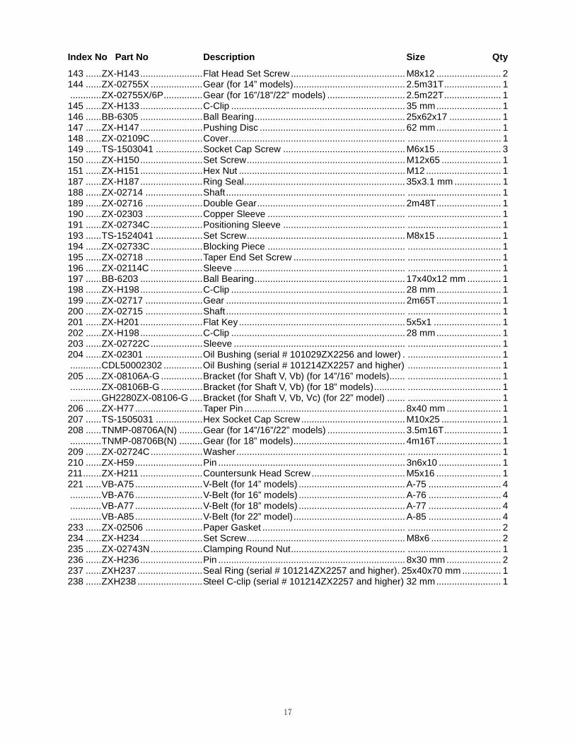
17
Index No Part No Description Size Qty
143 ...... ZX-H143 ........................ Flat Head Set Screw ............................................ M8x12 ......................... 2 144 ...... ZX-02755X .................... Gear (for 14” models) ........................................... 2.5m31T ...................... 1 ............ ZX-02755X/6P ............... Gear (for 16”/18”/22” models) .............................. 2.5m22T ...................... 1 145 ...... ZX-H133 ........................ C-Clip ................................................................... 35 mm ......................... 1 146 ...... BB-6305 ........................ Ball Bearing .......................................................... 25x62x17 .................... 1 147 ...... ZX-H147 ........................ Pushing Disc ........................................................ 62 mm ......................... 1 148 ...... ZX-02109C .................... Cover .................................................................... .................................... 1 149 ...... TS-1503041 .................. Socket Cap Screw ............................................... M6x15 ......................... 3 150 ...... ZX-H150 ........................ Set Screw ............................................................. M12x65 ....................... 1 151 ...... ZX-H151 ........................ Hex Nut ................................................................ M12 ............................. 1 187 ...... ZX-H187 ........................ Ring Seal .............................................................. 35x3.1 mm .................. 1 188 ...... ZX-02714 ...................... Shaft ..................................................................... .................................... 1 189 ...... ZX-02716 ...................... Double Gear ......................................................... 2m48T ......................... 1 190 ...... ZX-02303 ...................... Copper Sleeve ..................................................... .................................... 1 191 ...... ZX-02734C .................... Positioning Sleeve ............................................... .................................... 1 193 ...... TS-1524041 .................. Set Screw ............................................................. M8x15 ......................... 1 194 ...... ZX-02733C .................... Blocking Piece ..................................................... .................................... 1 195 ...... ZX-02718 ...................... Taper End Set Screw ........................................... .................................... 1 196 ...... ZX-02114C .................... Sleeve .................................................................. .................................... 1 197 ...... BB-6203 ........................ Ball Bearing .......................................................... 17x40x12 mm ............. 1 198 ...... ZX-H198 ........................ C-Clip ................................................................... 28 mm ......................... 1 199 ...... ZX-02717 ...................... Gear ..................................................................... 2m65T ......................... 1 200 ...... ZX-02715 ...................... Shaft ..................................................................... .................................... 1 201 ...... ZX-H201 ........................ Flat Key ................................................................ 5x5x1 .......................... 1 202 ...... ZX-H198 ........................ C-Clip ................................................................... 28 mm ......................... 1 203 ...... ZX-02722C .................... Sleeve .................................................................. .................................... 1 204 ...... ZX-02301 ...................... Oil Bushing (serial # 101029ZX2256 and lower) . .................................... 1 ............ CDL50002302 ............... Oil Bushing (serial # 101214ZX2257 and higher) .................................... 1 205 ...... ZX-08106A-G ................ Bracket (for Shaft V, Vb) (for 14”/16” models) ...... .................................... 1 ............ ZX-08106B-G ................ Bracket (for Shaft V, Vb) (for 18” models) ............ .................................... 1 ............ GH2280ZX-08106-G ..... Bracket (for Shaft V, Vb, Vc) (for 22” model) ....... .................................... 1 206 ...... ZX-H77 .......................... Taper Pin .............................................................. 8x40 mm ..................... 1 207 ...... TS-1505031 .................. Hex Socket Cap Screw ........................................ M10x25 ....................... 1 208 ...... TNMP-08706A(N) ......... Gear (for 14”/16”/22” models) .............................. 3.5m16T ...................... 1 ............ TNMP-08706B(N) ......... Gear (for 18” models) ........................................... 4m16T ......................... 1 209 ...... ZX-02724C .................... Washer ................................................................. .................................... 1 210 ...... ZX-H59 .......................... Pin ........................................................................ 3n6x10 ........................ 1 211 ....... ZX-H211 ........................ Countersunk Head Screw .................................... M5x16 ......................... 1 221 ...... VB-A75 .......................... V-Belt (for 14” models) ......................................... A-75 ............................ 4 ............ VB-A76 .......................... V-Belt (for 16” models) ......................................... A-76 ............................ 4 ............ VB-A77 .......................... V-Belt (for 18” models) ......................................... A-77 ............................ 4 ............ VB-A85 .......................... V-Belt (for 22” model) ........................................... A-85 ............................ 4 233 ...... ZX-02506 ...................... Paper Gasket ....................................................... .................................... 2 234 ...... ZX-H234 ........................ Set Screw ............................................................. M8x6 ........................... 2 235 ...... ZX-02743N .................... Clamping Round Nut ............................................ .................................... 1 236 ...... ZX-H236 ........................ Pin ........................................................................ 8x30 mm ..................... 2 237 ...... ZXH237 ......................... Seal Ring (serial # 101214ZX2257 and higher). 25x40x70 mm ............... 1 238 ...... ZXH238 ......................... Steel C-clip (serial # 101214ZX2257 and higher) 32 mm ......................... 1

18
6.1 Headstock Assembly III – Exploded View

19
6.2 Headstock Assembly III – Parts List
Index No Part No Description Size Qty
152 ...... ZX-02704 ...................... Spindle ................................................................. .................................... 1 153 ...... ZX-H153 ........................ Flat Key ................................................................ 10x8x40 mm ............... 1 154 ...... ZX-H154 ........................ Flat Key ................................................................ 10x8x50 mm ............... 1 155 ...... ZX-H155 ........................ Flat Key ................................................................ 12x8x50 mm ............... 1 156 ...... ZX-H156 ........................ Flat Key ................................................................ 14x9x50 mm ............... 1 157 ...... ZX-02701 ...................... Cam Lock ............................................................. .................................... 6 158 ...... ZX-H158 ........................ Spring ................................................................... 1x8x25 mm ................. 6 159 ...... ZX-02703 ...................... Cam Positioning Screw ........................................ .................................... 6 160 ...... TS-1505041 .................. Hex Socket Cap Screw ........................................ M10x28 ....................... 6 161 ...... ZX-02102-G .................. Bearing Front Cover ............................................. .................................... 1 162 ...... ZX-02501 ...................... Gasket .................................................................. .................................... 1 163 ...... ZX-02702 ...................... Oil Splashing Ring ................................................ .................................... 1 164 ...... NN3024/P5 .................... Taper Roller Bearing ............................................ 120x180x46 mm ......... 1 165 ...... ZX-02726 ...................... Lining .................................................................... .................................... 1 168 ...... ZX-02725A .................... Round Nut w/Screw ............................................. .................................... 1 169 ...... ZX-02723 ...................... Gear ..................................................................... 3m98T ......................... 1 170 ...... ZX-02722 ...................... Gear ..................................................................... 3m50T ......................... 1 171 ...... ZX-02721 ...................... Gear ..................................................................... 3m58T ......................... 1 172 ...... ZX-02720A .................... Round Nut w/Screw ............................................. .................................... 1 175 ...... ZX-02710 ...................... Gear ..................................................................... 2m65T ......................... 1 176 ...... 51120/P5 ....................... Thrust Bearing ..................................................... 100x135x25 mm ......... 1 179 ...... BB-7020AC/P5 .............. Angular Bearing ................................................... 100x150x24 mm ......... 1 184 ...... ZX-02713A .................... Round Nut w/Screw ............................................. .................................... 1 212 ...... ZX-H212 ........................ Drain Plug (14” models, serial # 001204ZX258 and lower) ...................... 1 ............ ZX-H212 ........................ Drain Plug (16” models, serial #010312ZX293 and lower, also includes serial # 010319ZX298 and 299) .......................... .................................... 1 ............ ZX-H212 ........................ Drain Plug (18” models, serial # 010416ZX313 and lower) ...................... 1 ............ ZX-H212A ..................... Drain Plug (14” models, serial # 010105ZX263 and higher) .................... 1 ............ ZX-H212A ..................... Drain Plug (16” models, serial #010319ZX294 and higher, except for serial # 010319ZX298 and 299) ..................... .................................... 1 ............ ZX-H212A ..................... Drain Plug (18” models, serial # 010514ZX323 and higher) .................... 1 ............ ZX-H212A ..................... Drain Plug (22” model) ......................................... Z3/8”............................ 1 213 ...... ZX-02101A .................... Headstock Casting (14” models, serial # 001204ZX258 and lower) ........ 1 ............ ZX-02101AN ................. Headstock Casting (14” models, serial # 010105ZX263 and lower) ........ 1 ............ ZX-02101AN-G ............. Headstock Casting (14” models) ........................ .................................... 1 ............ ZX-01201B .................... Headstock Casting (16” models, serial # 010312ZX293 and lower, also includes serial # 110319ZX298 and 299) ............ .................................... 1 ............ ZX-02101BN ................. Headstock Casting (16” models, serial # 010319ZX294 and lower except for serial # 010319ZX298 and 299) ......... .................................... 1 ............ ZX-02101BN-G ............. Headstock Casting (16” models) ......................... .................................... 1 ............ ZX-02101C .................... Headstock Casting (18” models, serial # 010416ZX313 and lower) ........ 1 ............ ZX-02101CN ................. Headstock Casting (18” models, serial # 010514ZX323 and lower) ........ 1 ............ ZX-02101CN-G ............. Headstock Casting (18” models) ........................ .................................... 1 ............ GH2280ZX-02101 ......... Headstock Casting (22” model) ........................... .................................... 1 ............ GH2280ZX-02101-G ..... Headstock Casting (22” model) ........................... .................................... 1 224 ...... ZX-G38-3A .................... Screw ................................................................... .................................... 1 226 ...... ZX-H226 ........................ Hex Socket Cap Screw ........................................ M8x28 ......................... 9 227 ...... ZX-02502F .................... Gasket(The part is canceled from serial # 130415ZX2706) ................ 1 228 ...... ZX-02108F .................... Bearing Support ................................................... .................................... 1 229 ...... ZX-02711F..................... Sleeve .................................................................. .................................... 1 230 ...... ZX-02510F .................... Gasket .................................................................. .................................... 1 231 ...... ZX-02761F .................... Bearing Back Cover ............................................. .................................... 1 232 ...... ZX-H232 ........................ Screw ................................................................... M5x10 ......................... 6

20
7.1 Headstock Assembly IV – Exploded View

21
7.2 Headstock Assembly IV – Parts List
Index No Part No Description Size Qty
214 ...... ZX-08302A-G ................ Back Cover (for 14” models) ................................ .................................... 1 ............ ZX-08302B-G ................ Back Cover (for 16” models) ................................ .................................... 1 ............ ZX-08302C-G ................ Back Cover (for 18” models) ................................ .................................... 1 ............ GH2280ZX-08301-G ..... Back Cover (for 22” model) .................................. .................................... 1 215 ...... ZX-08114A-G ................ Rear Side Plate (for 14” models) ......................... .................................... 1 ............ ZX-08114B-G ................ Rear Side Plate (for 16” models) ......................... .................................... 1 ............ ZX-08114C-G ................ Rear Side Plate (for 18” models) ......................... .................................... 1 ............ GH2280ZX-08114-G ..... Rear Side Plate (for 22” model) ........................... .................................... 1 216 ...... ZX-08113A-G ................ Front Side Plate (for 14” models) ......................... .................................... 1 ............ ZX-08113B-G ................ Front Side Plate (for 16” models) ......................... .................................... 1 ............ ZX-08113C-G ................ Front Side Plate (for 18” models) ......................... .................................... 1 ............ GH2280ZX-08113-G ..... Front Side Plate (for 22” model)........................... .................................... 1 217 ...... TS-1504051 .................. Socket Cap Screw ............................................... M8x25 ......................... 4 218 ...... ZX-H218 ........................ Taper Pin .............................................................. 6x25 mm ..................... 2 219 ...... TS-1503051 .................. Socket Cap Screw ............................................... M6x20 ......................... 8 220 ...... TS-1514021 .................. Socket Cap Screw ............................................... M6x15 ......................... 3 220a .... GB97.2-6 ....................... Washer ................................................................. 6 mm ........................... 3 222 ...... ZX-08712 ...................... Upper Hinge ......................................................... .................................... 2 223 ...... ZX-H223 ........................ Pin ........................................................................ 6n6x40 ........................ 2 225 ...... ZX-08711 ....................... Lower Hinge ......................................................... .................................... 2 226 ...... GH-1440ZX-11304-6 ..... Warning Plate (serial #160410ZX3032 and higher) .................................. 1 ............ GH-1640ZX-11304-7 ..... Warning Plate (serial #160410ZX3032 and higher) .................................. 1 ............ GH-1660ZX-11304-8 ..... Warning Plate (serial #160410ZX3032 and higher) .................................. 1 ............ GH-1860ZX-11304-9 ..... Warning Plate (serial #160410ZX3032 and higher) .................................. 1 ............ GH-1880ZX-11304-10 ... Warning Plate (serial #160410ZX3032 and higher) .................................. 1 ............ GH-2280ZX-11304-11 ... Warning Plate (serial #160410ZX3032 and higher) .................................. 1

22
8.1 Change Gear Box Assembly I – Exploded View

23
8.2 Change Gear Box Assembly I – Parts List
Index No Part No Description Size Qty
1 .......... ZX-08101-G .................. Change Gear Box Casting ................................... .................................... 1 2 .......... ZX-08108-G .................. Front Cover .......................................................... .................................... 1 5 .......... ZX-05104C-G ................ Hand Wheel ......................................................... .................................... 1 6 .......... ZX-05301C .................... Sign Plate (serial #160401ZX3031 and lower) .... .................................... 1 ............ C6136ZK-02304-1 ......... Sign Plate (serial #160410ZX3032 and higher) ... .................................... 1 6a ........ GB2672-M3×6 ............. Screw (serial # 160410ZX3032 and higher) ........ M3x6 ........................... 2 7 .......... ZX-08708 ...................... Positioning Disc ................................................... .................................... 1 9 .......... ZX-08111 ....................... Crank .................................................................... .................................... 1 10 ........ ZX-08705 ...................... Connecting Rod ................................................... .................................... 1 11 ......... ZX-08304 ...................... Sliding Block......................................................... .................................... 1 12 ........ ZX-05103C .................... Cam ...................................................................... .................................... 1 13 ........ ZX-05702C .................... Roller .................................................................... .................................... 2 14 ........ ZX-08109 ...................... Crank .................................................................... .................................... 1 15 ........ ZX-08110 ....................... Bushing ................................................................ .................................... 1 16 ........ ZX-08704 ...................... Rotating Shaft ...................................................... .................................... 1 17 ........ ZX-08703 ...................... Connecting Rod ................................................... .................................... 1 18 ........ ZX-08304 ...................... Sliding Block......................................................... .................................... 1 26 ........ ZX-C26 .......................... Cross Head Screw ............................................... M4x12 ......................... 3 28 ........ TS-1504051 .................. Socket Cap Screw ............................................... M8x25 ......................... 4 29 ........ TS-1516051 .................. Hex Socket Cap Screw ........................................ M10x40 ....................... 2 30 ........ TS-1525021 .................. Set Screw ............................................................. M10x12 ....................... 1 31 ........ ZX-C31 .......................... Flat Head Set Screw ............................................ M6x8 ........................... 1 33 ........ ZX-C33 .......................... Taper Pin .............................................................. 4x45 mm ..................... 1 34 ........ ZX-C34 .......................... Taper Pin .............................................................. 6x30 mm ..................... 2 35 ........ ZX-C35 .......................... Taper Pin .............................................................. 6x50 mm ..................... 1 36 ........ ZX-C36 .......................... Pin ........................................................................ 10m6x40 ..................... 2 37 ........ ZX-C37 .......................... Pin ........................................................................ 10m6x50 ..................... 2 38 ........ ZX-H5 ............................ Steel Ball .............................................................. 8 mm ........................... 1 42 ........ ZX-C42 .......................... Spring ................................................................... 1x8x30 ........................ 1 43 ........ ZX-08716-G .................. Splash Guard ...................................................... .................................... 1 44 ........ GB818-M6x12 .............. Cross Recessed Pen Head Screw .................... M6x12 ......................... 2 44a ...... GB97.2-6 ...................... Washer ................................................................ 6 mm .......................... 2 45 ........ GB818-M5x12 .............. Cross Recessed Pen Head Screw .................... M5x12 ......................... 3 45a ...... GB97.2-5 ...................... Washer ................................................................ 5 mm .......................... 3 46 ........ ZX-08715-G .................. Splash Guard ...................................................... .................................... 1

24
9.1 Change Gear Box Assembly II – Exploded View

25
9.2 Change Gear Box Assembly II – Parts List
Index No Part No Description Size Qty
3 .......... ZX-08104-G .................. End Cover ............................................................ .................................... 4 4 .......... ZX-08103-G .................. Bearing Support ................................................... .................................... 1 19 ........ ZX-08107 ...................... Gear ..................................................................... 3m36T ......................... 1 20 ........ ZX-08105 ...................... Double Gear ......................................................... 3.75m28T/3m30T ....... 1 21 ........ ZX-08702 ...................... Shaft ..................................................................... .................................... 1 22 ........ ZX-08701 ...................... Shaft ..................................................................... .................................... 1 23 ........ ZX-08710 ...................... Gear ..................................................................... 3.75m27T .................... 1 24 ........ ZX-08709 ...................... Gear ..................................................................... 3m41T ......................... 1 25 ........ ZX-08102 ...................... Double Gear ......................................................... 3.75m30T/3m29T ....... 1 27 ........ ZX-C27 .......................... Slotted Cheese Head Screw ................................ M5x12 ....................... 15 32 ........ ZX-C32 .......................... Flat Head Set Screw ............................................ M10x12 ....................... 1 39 ........ BB-6203ZZ/P6 .............. Ball Bearing .......................................................... 17x40x12 .................... 5 40 ........ ZX-C40 .......................... C-Clip ................................................................... 25 mm ......... 4(5 for 22”) 41 ........ ZX-C41 .......................... C-Clip ................................................................... 40 mm ......................... 1 43 ........ ZX-C43 .......................... Oil Cup ................................................................. 8 mm .......... 1 (2 for 22”) 44 ........ TNMP08108 .................. Washer ................................................................. ................... 1 (2 for 22”) 45 ........ TNMP08102 .................. Splined Sleeve ..................................................... .................................... 1 46 ........ TNMP08504 .................. Gear ..................................................................... 3m41T ......................... 1 47 ........ TNMP08501A ................ Gear (for 14”/16”/22” models) .............................. 3.5m36T ...................... 1 ............ TNMP08501B ................ Gear (for 18” models) ........................................... 4m36T ......................... 1 48 ........ ZX-05502C .................... Oil Bushing ........................................................... .................................... 1 49 ........ ZX-08707 ...................... Shaft Vb ............................................................... .................................... 1 50 ........ ZX-C50 .......................... Flat Head Set Screw ............................................ M8x10 ........ 1 (2 for 22”) 51 ........ GH2280ZX-08112 ......... Gear (for 22” model) ............................................ 3m30T ......................... 1 52 ........ GH2280ZX-1052 ........... Washer ................................................................. .................................... 1 53 ........ GH2280ZX-1053 ........... Oil Bushing ........................................................... .................................... 1 54 ........ GH2280ZX-08707 ......... Axis Vc (for 22” model) ........................................ .................................... 1

26
10.1 Quick Change Gear Box I – Exploded View

27
10.2 Quick Change Gear Box I – Parts List
Index No Part No Description Size Qty
1 .......... KLS1740A-05152-G ...... Upper Cover ......................................................... .................................... 1 2 .......... TS-1503071 .................. Hex Socket Cap Screw ........................................ M6x30 ......................... 2 6 .......... TS-1504031 .................. Hex Socket Cap Screw ........................................ M8x16 ....................... 10 7 .......... ZX-05109-G .................. Rear Cover ........................................................... .................................... 1 8 .......... ZX-05502 ...................... Gasket .................................................................. .................................... 1 9 .......... ZX-Q09 .......................... Countersunk Head Screw .................................... M10x18 ....................... 1 10 ........ ZX-05101-G .................. Feedbox Casting .................................................. .................................... 1 11 ......... ZX-05501 ...................... Gasket .................................................................. .................................... 1 12 ........ ZX-05108-G .................. Flange .................................................................. .................................... 1 13 ........ TS-1504031 .................. Hex Socket Cap Screw ........................................ M8x16 ......................... 6 14 ........ ZX-05151-G .................. Extending Plate .................................................... .................................... 1 15 ........ TS-1503131 .................. Hex Socket Cap Screw ........................................ M6x60 ......................... 4 19 ........ ZX-Q19 .......................... Pipe ...................................................................... M10x10 ....................... 1 20 ........ TS-1491061 .................. Hex Cap Bolt ........................................................ M10x40 ....................... 2 21 ........ ZX-H68 .......................... Taper Pin .............................................................. 6x35 mm ..................... 2 22 ........ ZX-05738 ...................... Control Shaft ........................................................ .................................... 1 23 ........ ZX-05739 ...................... Sliding Key ........................................................... .................................... 3 24 ........ ZX-05128 ...................... Sliding Sleeve ...................................................... .................................... 3 25 ........ ZX-Q25 .......................... Flat Head Set Screw ............................................ M5x8 ........................... 4 26 ........ ZX-05125 ...................... Right Fork ............................................................. .................................... 1 27 ........ ZX-05126 ...................... Middle Fork .......................................................... .................................... 1 28 ........ ZX-05127 ...................... Left Fork ............................................................... .................................... 1 29 ........ ZX-Q29 .......................... Ring Seal .............................................................. 32x3.1 mm .................. 1 30 ........ ZX-Q30 .......................... Taper Pin (serial #121220ZX2630 and lower) ..... 4x25 mm ..................... 2 ............ GB877- 4x30 ................. Taper Pin (serial #130102ZX2631 and higher) .... 4x30 mm ..................... 2 31 ........ ZX-05129 ...................... Cover .................................................................... .................................... 1 32 ........ ZX-Q32 .......................... Pin ........................................................................ 5n6x15 ........................ 1 33 ........ ZX-Q33 .......................... Cheese Head Screw ............................................ M5x16 ......................... 3 34 ........ ZX-05122 ...................... Cam ...................................................................... .................................... 1 35 ........ ZX-05728 ...................... Rolling Sleeve ...................................................... .................................... 5 36 ........ ZX-05729 ...................... Poking Key ........................................................... .................................... 3 37 ........ ZX-05123 ...................... Crank .................................................................... .................................... 1 38 ........ ZX-Q38 .......................... Pin ........................................................................ 8n6x32 ........................ 5 39 ........ ZX-Q39 .......................... Pin ........................................................................ 6n6x20 mm ................. 5 40 ........ ZX-05124 ...................... Crank .................................................................... .................................... 1 41 ........ ZX-05111 ....................... Sleeve .................................................................. .................................... 1 42 ........ ZX-05726 ...................... Lever Shaft ........................................................... .................................... 1 43 ........ ZX-Q43 .......................... Taper Pin (serial #121220ZX2630 and lower) ..... 4x32 mm ..................... 2 ............ GB877- 4x35 ................. Taper Pin (serial #130102ZX2631 and higher) .... 4x35 mm ..................... 2 44 ........ ZX-Q44 .......................... Taper Pin .............................................................. 4x65 mm ..................... 1 45 ........ ZX-05121 ...................... Crank .................................................................... .................................... 1 46 ........ ZX-05118 ....................... Cam ...................................................................... .................................... 1 47 ........ ZX-05120 ...................... Crank .................................................................... .................................... 1 48 ........ ZX-05116 ....................... Fork ...................................................................... .................................... 1 49 ........ ZX-Q49 .......................... Pin ........................................................................ 8n6x18 ........................ 2 50 ........ ZX-05117 ....................... Sleeve .................................................................. .................................... 1 51 ........ ZX-05737 ...................... Lever Shaft ........................................................... .................................... 1 52 ........ ZX-C33 .......................... Taper Pin .............................................................. 4x45 mm ..................... 2 53 ........ ZX-05115 ....................... Fork ...................................................................... .................................... 1 54 ........ ZX-05119 ....................... Crank .................................................................... .................................... 1 55 ........ ZX-05735 ...................... Pin ........................................................................ .................................... 1 56 ........ ZX-05112 ....................... Fork ...................................................................... .................................... 1 57 ........ ZX-05113 ....................... Crank .................................................................... .................................... 1 58 ........ ZX-05730 ...................... Small Shaft ........................................................... .................................... 1 59 ........ ZX-05731 ...................... Big Gear ............................................................... 1m44T ......................... 1 60 ........ ZX-05732 ...................... Small Gear ........................................................... 1m22T ......................... 1

28
Index No Part No Description Size Qty
61 ........ ZX-05114 ....................... Sleeve .................................................................. .................................... 1 62 ........ ZX-05734 ...................... Lever Shaft ........................................................... .................................... 1 63 ........ ZX-05503 ...................... Gasket .................................................................. .................................... 1 64 ........ ZX-05110-G ................... Front Cover .......................................................... .................................... 1 65 ........ TS-1505021 .................. Hex Socket Cap Screw ........................................ M10x20 ....................... 5 66 ........ ZX-Q66 .......................... Taper Pin .............................................................. 5x35 mm ..................... 6 67 ........ ZX-05303A .................... Sign Plate (serial #110930ZX2364 and lower) .... .................................... 1 ............ ZX-05303B .................... Sign Plate (serial #160401ZX3031and lower) ..... .................................... 1 ............ ZX-08301-31 ................. Sign Plate (serial #160410ZX3032 and higher) ... .................................... 1 68 ....... ZX-Q68 .......................... Cross Head Screw (serial #160401ZX3031 and lower) M3x6 .................. 7 ............ GB2672-M3x6 ............... Screw (serial #160410ZX3032 and higher) ......... M3x6 ......................... 11 69 ........ ZX-Q69 .......................... Oil Sight Glass ..................................................... 20 mm ......................... 1 70 ........ ZX-05727 ...................... Positioning Disc ................................................... .................................... 1 71 ........ ZX-Q71 .......................... Countersunk Head Screw .................................... M4x12 ......................... 9 72 ........ ZX-05740-G .................. Lever .................................................................... .................................... 1 73 ........ ZX-05130A-G ................ Lever Support....................................................... .................................... 1 74 ........ ZX-05301 ...................... Sign Disc (serial #160401ZX3031 and lower) ..... .................................... 2 ............ C6136ZK-02304-1 ......... Sign Disc (serial #160410ZX3032 and higher) .... .................................... 2 74a ...... ZX-05301 ...................... Sign Disc (serial #160401ZX3031 and lower) ..... .................................... 1 ............ C6136-02306 ................ Sign Disc (serial #160410ZX3032 and higher) .... .................................... 1 75 ........ ZX-H5 ............................ Steel Ball .............................................................. 8 mm ........................... 3 76 ........ ZX-Q76 .......................... Compression Spring ............................................. YZ-1x8x25 .................. 3 77 ........ ZX-H3 ............................ Flat End Set Screw .............................................. M10x12 ....................... 3 78 ........ ZX-05736 ...................... Positioning Disc ................................................... .................................... 1 79 ........ ZX-05140-G .................. Hand Wheel ......................................................... .................................... 2 80 ........ ZX-05733 ...................... Positioning Disc ................................................... .................................... 1 82 ........ GB70-M8×5 ................. Hex Socket Cap Screw ........................................ M8x5 ........................... 1 83 ........ 1440R-05752A-G .......... Board .................................................................... .................................... 1

29
11.1 Quick Change Gear Box II – Exploded View

30
11.2 Quick Change Gear Box II – Parts List
Index No Part No Description Size Qty
81 ........ ZX-05104 ...................... Middle Bearing Support ....................................... .................................... 2 82 ........ ZX-Q82 .......................... Taper End Set Screw ........................................... M10x16 ....................... 2 83 ........ ZX-B23 .......................... C-Clip ................................................................... 20 mm ......................... 3 84 ........ ZX-Q84 .......................... C-Clip ................................................................... 42 mm ......................... 5 85 ........ BB-6004 ........................ Single Row Radial Ball Bearing ........................... 20x42x12 mm ............. 5 86 ........ ZX-05721 ...................... Shaft ..................................................................... .................................... 1 87 ........ ZX-05722 ...................... Double Gear ......................................................... 2m26T/2m52T ............ 1 88 ........ ZX-Q88 .......................... Iron Wire ............................................................... 1x190 mm ................... 2 89 ........ TS-1524051 .................. Set Screw ............................................................. M8x20 ......................... 2 90 ........ ZX-05720 ...................... Positioning Sleeve ............................................... .................................... 1 91 ........ ZX-05719 ...................... Gear ..................................................................... 2.25m28T .................... 1 92 ........ ZX-05718 ...................... Double Gear ......................................................... 2m26T/2m28T ............ 1 93 ........ ZX-05717 ...................... Gear ..................................................................... 3.5m20T ...................... 1 94 ........ ZX-05716 ...................... Double Gear ......................................................... 3.5m18T/3.5m19T ...... 1 95 ........ ZX-05715 ...................... Gear ..................................................................... 3.25m22T .................... 1 96 ........ ZX-05714 ...................... Double Gear ......................................................... 3.25m24T/3.25m23T .. 1 97 ........ BB-6205 ........................ Single Row Radial Ball Bearing ........................... 25x52x15 mm ............. 2 98 ........ ZX-C40 .......................... C-Clip ................................................................... 25 mm ......................... 3 99 ........ ZX-05125-G .................. Shaft End Cover ................................................... .................................... 1 100 ...... TS-1504041 .................. Hex Socket Cap Screw ........................................ M8x18 ......................... 2 101 ...... ZX-05704 ...................... Spacer .................................................................. .................................... 1 102 ...... ZX-05705 ...................... Double Gear ......................................................... 2m52T/2m26T ............ 1 103 ...... ZX-05502C .................... Oil Bushing ........................................................... .................................... 3 104 ...... ZX-05105 ...................... Sleeve .................................................................. .................................... 2 105 ...... ZX-05707 ...................... Double Gear ......................................................... 2m39T/2m26T ............ 1 106 ...... ZX-Q106 ........................ Iron Wire ............................................................... 1x160 mm ................... 3 107 ...... TS-1524031 .................. Set Screw ............................................................. M8x12 ......................... 3 108 ...... ZX-05714C .................... Fixed Bushing ...................................................... .................................... 1 109 ...... ZX-05710 ...................... Shaft ..................................................................... .................................... 1 110 ....... ZX-05709 ...................... Double Gear ......................................................... 2m48T/2.25m42T ....... 1 111 ....... ZX-05711 ....................... Sliding Gear ......................................................... 3.5m24T ...................... 1 112 ....... ZX-05712 ...................... Sliding Gear ......................................................... 3.25m24T .................... 1 113 ....... ZX-05713 ...................... Sleeve .................................................................. .................................... 1 114 ....... ZX-G51-1 ...................... Spacer .................................................................. 32 mm ......................... 1 115 ....... ZX-05106-G .................. Bearing Support ................................................... .................................... 1 116 ....... TS-1504051 .................. Hex Socket Cap Screw ........................................ M8x25 ......................... 3 141 ...... ZX-05504 ...................... Gasket .................................................................. .................................... 1 142 ...... ZX-05505 ...................... Gasket .................................................................. .................................... 1

31
12.1 Quick Change Gear Box III – Exploded View

32
12.2 Quick Change Gear Box III – Parts List
Index No Part No Description Size Qty
66 ........ ZX-Q66 .......................... Taper Pin .............................................................. 5x35 mm ..................... 6 83 ........ ZX-Q83 .......................... C-Clip ................................................................... 20 mm ......................... 3 84 ........ ZX-Q84 .......................... C-Clip ................................................................... 42 mm ......................... 5 85 ........ BB104............................ Single Row Radial Ball Bearing ........................... 20x42x12 mm ............. 5 98 ........ ZX-Q98 .......................... C-Clip ................................................................... 25 mm ......................... 3 106 ...... ZX-Q106 ........................ Iron Wire ............................................................... 1x160 mm ................... 3 107 ...... TS-1524031 .................. Set Screw ............................................................. M8x12 ......................... 3 117 ....... ZX-05113C .................... Shaft Coupling ...................................................... .................................... 2 118 ....... ZX-Q118 ........................ Round Nut ............................................................ M24x1.5 ...................... 2 119 ....... TS-1503021 .................. Hex Socket Cap Screw ........................................ M6x10 ......................... 2 120 ...... ZX-05114C-G ................ Cover .................................................................... .................................... 1 121 ...... BB-51105 ....................... Thrust Bearing ..................................................... 25x42x11 mm.............. 2 122 ...... ZX-Q122 ........................ Spacer .................................................................. 25 mm ......................... 2 123 ...... BB-6305 ........................ Ball Bearing .......................................................... 25x62x17 mm ............. 1 124 ...... ZX-05725 ...................... Shaft ..................................................................... .................................... 1 125 ...... ZX-Q125 ........................ Key ....................................................................... 8x7x50 mm ................. 1 126 ...... ZX-05724 ...................... Double Gear ......................................................... 2.25m35T/2.25m36T .. 1 127 ...... ZX-05723 ...................... Gear ..................................................................... 2.5m36T ...................... 1 128 ...... ZX-05107 ...................... Sleeve .................................................................. .................................... 2 129 ...... BB-6005 ........................ Ball Bearing .......................................................... 25x47x12 mm ............. 1 130 ...... TS-1525021 .................. Set Screw ............................................................. M10x12 ....................... 2 131 ...... ZX-05103 ...................... Bearing Support ................................................... .................................... 1 132 ...... ZX-05701 ...................... Shaft ..................................................................... .................................... 1 133 ...... ZX-Q133 ........................ Half Circle Key ..................................................... 6x22 mm ..................... 1 134 ...... ZX-05703 ...................... Gear ..................................................................... 2.5m36T ...................... 1 135 ...... ZX-05102 ...................... Bearing Support ................................................... .................................... 1 136 ...... ZX-05702 ...................... Double Gear ......................................................... 2.5m24T/2.25m35T .... 1 137 ...... ZX-05708 ...................... Shaft ..................................................................... .................................... 1 138 ...... ZX-05706 ...................... Triple Gear ........................................................... 2m39T/2m52T/2m26T 1 139 ...... BB-6203 ........................ Ball Bearing .......................................................... 17x40x12 mm ............. 1 140 ...... ZX-Q140 ........................ C-Clip ................................................................... 17 mm ......................... 1

33
13.1 Apron Assembly I – Exploded View

34
13.2 Apron Assembly I – Parts List
Index No Part No Description Size Qty
1 .......... TL06101-G .................... Apron Casting ...................................................... .................................... 1 2 .......... TL06103-G .................... Bottom Cover ....................................................... .................................... 1 3 .......... TS-1540072 .................. Hex Nut ................................................................ M10 ............................. 1 4 .......... ZX-A4 ............................ Flat Head Set Screw ............................................ M10x70 ....................... 1 5 .......... TL06502 ........................ Cushion Cap ........................................................ .................................... 1 6 .......... ZX-A6 ............................ Pin ........................................................................ 6n6x16 ........................ 2 7 .......... ZX-A7 ............................ Tensile Spring ....................................................... YI1.2x9x50 .................. 1 8 .......... TL06734 ........................ Lever .................................................................... .................................... 1 9 .......... ZX-A9 ............................ Pin ........................................................................ 8n6x30 ........................ 1 10 ........ ZX-A10 .......................... Pin ........................................................................ 6n6x18 ........................ 1 11 ......... TL06701-A .................... Pushing Rod......................................................... .................................... 1 12 ........ ZX-A12 .......................... Oil Seal ................................................................. 15x2.4 mm .................. 1 13 ........ BB60016 ....................... Ball Bearing .......................................................... 6x17x6 mm ................. 1 14 ........ ZX-A6 ............................ Pin ........................................................................ 6n6x16 ........................ 1 15 ........ GB70 ............................. Hex Socket Cap Screw ........................................ M8x6 ........................... 1 16 ........ ZX-B34 .......................... Taper Pin .............................................................. 5x30 mm ..................... 2 17 ........ TS-1504041 .................. Hex Socket Cap Screw ........................................ M8x20 ......................... 6 18 ........ TL06501 ........................ Gasket .................................................................. .................................... 1 19 ........ TL06307 ........................ Sign Plate (serial #160401ZX3031 and lower) .... .................................... 1 ............ C0632B05302-2 ............ Sign Plate (serial #160410ZX3032 and higher) ... .................................... 1 19a ...... GB2672- M3x6 .............. Screw (serial #160410ZX3032 and higher) ......... M3x6 ........................... 6 20 ........ TL06716-G .................... Lever .................................................................... .................................... 1 21 ........ ZX-06122-G .................. Lever Support....................................................... .................................... 1 22 ........ ZX-B27 .......................... Taper Pin .............................................................. 6x60 mm ..................... 1 23 ........ TL06717 ........................ Half Nut Shaft ....................................................... .................................... 1 24 ........ TL06111 ......................... Positioning Block .................................................. .................................... 1 25 ........ ZX-A25 .......................... Thread Tail Taper Pin ........................................... 6x25 mm ..................... 1 26 ........ TS-1523031 .................. Set Screw ............................................................. M6x10 ......................... 1 27 ........ ZX-06733 ...................... Half Nut Control Plate .......................................... .................................... 1 28 ........ ZX-A28 .......................... Taper Pin .............................................................. 6x55 mm ..................... 1 29 ........ ZX-06732 ...................... Pin ........................................................................ .................................... 2 30 ........ ZX-06302 ...................... Half Nut (serial # 010611ZX349 and lower) ......... .................................... 1 ............ ZX-06302N .................... New Half Nut (serial # 010618ZX350 and higher) .................................... 1 31 ........ TS-1540072 .................. Hex Nut ................................................................ M10 ............................. 1 32 ........ ZX-A32 .......................... Cylindrical End Set Screw .................................... M10x60 ....................... 1 33 ........ ZX-06121 ...................... Gib ........................................................................ .................................... 1 34 ........ ZX-06731 ...................... Cylindrical End Set Screw .................................... .................................... 3 35 ........ TS-1540061 .................. Hex Nut ................................................................ M8 ............................... 3 36 ........ ZX-A36 .......................... Set Screw ............................................................. M8x32 ......................... 1 37 ........ ZX-A37 .......................... Oil Sight Glass ..................................................... 20 mm ......................... 1 69 ........ TL06727 ........................ Gear (serial # 010611ZX349 and lower) .............. 2m25T ......................... 1 ............ TL06727N ..................... New Gear (serial # 010618ZX350 and higher) .... 2m25T ......................... 1 70 ........ TL06728 ........................ Sliding Key ........................................................... .................................... 2 71 ........ TL06121 ........................ Spacer (serial # 010611ZX349 and lower) ........... .................................... 2 ............ TL06121N ..................... New Spacer (serial # 010618ZX350 and higher) . .................................... 2 72 ........ TL06304 ........................ Positioning Sleeve (serial # 010611ZX349 and lower) ............................. 2 ............ TL06304N ..................... New Positioning Sleeve (serial # 010618ZX350 and higher) ................... 2 73 ........ ZX-A73 .......................... Ring Seal For Rotating ......................................... 3x55 mm ..................... 2 74 ........ ZX-A74 .......................... Oil Seal ................................................................. 35x3.1 mm .................. 1 75 ........ TL06729 ........................ Sleeve (serial # 010611ZX349 and lower) ........... .................................... 1 ............ TL06729N ..................... New Sleeve (serial # 010618ZX350 and higher) . .................................... 1 122 ..... TL06302 ........................ Sign Plate (serial #160401ZX3031 and lower) .... .................................... 1 ............ TL06302B-10 ................ Sign Plate (serial # 160410ZX3032 and higher) .. .................................... 1 123 ...... TL06730 ........................ Shaft ..................................................................... .................................... 1 124 ...... BB-51104 ....................... Thrust Bearing ..................................................... .................................... 2 125 ...... TL06305 ........................ Sleeve .................................................................. .................................... 2

35
Index No Part No Description Size Qty
126 ...... TL06726 ........................ Worm (serial # 010611ZX349 and lower) ............ .................................... 1 ............ TL06726N ..................... New Worm (serial # 010618ZX350 and higher) .. .................................... 1 127 ...... TL06122 ........................ Worm Support (serial # 010611ZX349 and lower) .................................... 1 ............ TL06122N ..................... New Worm Support (serial # 010618ZX350 and higher) .......................... 1 128 ...... TL06720 ........................ Control Plate ........................................................ .................................... 1 129 ...... TS-1514031 .................. Hex Socket Cap Screw ........................................ M6x20 ......................... 4 130 ...... ZX-A130 ........................ Taper Pin .............................................................. 4x20 mm ..................... 1 131 ...... TS-1524031 .................. Set Screw ............................................................. M8x12 ......................... 2 132 ...... ZX-A132 ........................ Screw ................................................................... M8x25 ......................... 2 133 ...... ZX-A133 ........................ Cylindrical Tensile Spring ..................................... LI-1.6x10x58 ............... 1 134 ...... TL06503 ........................ Gasket .................................................................. .................................... 1 135 ...... TL06114-G .................... Back Cover........................................................... .................................... 1 136 ...... TS-1514011 ................... Hex Socket Cap Screw ........................................ M6x12 ......................... 5 137 ...... ZX-A137 ........................ Set Screw ............................................................. M8x30 ......................... 2 138 ...... ZX-A138 ........................ Iron Wire ............................................................... 1x50 mm ..................... 2 139 ...... ZX-A139 ........................ Oil Conducting Cord ............................................. 3x100 mm ................... 2 140 ...... ZX-A140 ........................ Screw ................................................................... M10x40 ....................... 1 158 ...... TS-1540041 .................. Hex Nut ................................................................ M6 ............................... 1 159 ...... TL06124 ........................ Bracket ................................................................. .................................... 1 160 ...... ZX-A160 ........................ Taper Pin .............................................................. 5x25 mm ..................... 2 161 ...... TL06308-G .................... Bracket ................................................................. .................................... 1 162 ...... TS-1503041 .................. Hex Socket Cap Screw ........................................ M6x16 ......................... 1 163 ...... TL06120 ........................ Sleeve .................................................................. .................................... 1

36
14.1 Apron Assembly II – Exploded View

37
14.2 Apron Assembly II – Parts List
Index No Part No Description Size Qty
38 ........ ZXB23 ........................... C-Clip ................................................................... 20 mm ......................... 1 39 ........ BB6204 ......................... Ball Bearing .......................................................... 20x47x14 .................... 1 40 ........ TL06705 ........................ Gear ..................................................................... 2m65T ......................... 1 41 ........ ZXA41 ........................... Taper Pin (serial #121220ZX2630 and lower) ..... 6x40 mm ..................... 1 ............ GB877- 6x45 ................. Taper Pin (serial #130102ZX2631 and higher) .... 6x45 mm ..................... 1 42 ........ ZXC40 ........................... C-Clip ................................................................... 25 mm ......................... 1 43 ........ ZX06127N ..................... New Bearing Support ........................................... .................................... 1 44 ........ TS1504041 .................... Hex Socket Cap Screw ........................................ M8x18 ......................... 3 45 ........ BB6205Z ....................... Ball Bearing .......................................................... 25x52x15 mm ............. 1 46 ........ ZXA46 ........................... C-Clip ................................................................... 52 mm ......................... 1 47 ........ TL06704N ..................... New Shaft ............................................................. 2m14T ......................... 1 48 ........ TL06706 ........................ Hand Wheel Shaft ................................................ 2mx15T ....................... 1 49 ........ ZXH10 ........................... Half Circle Key ..................................................... 4x16 mm ..................... 1 50 ........ ZXA50 ........................... Oil Cup ................................................................. 8 mm ........................... 1 51 ........ TL06104 ........................ Lever Support....................................................... .................................... 1 52 ........ TS1514031 .................... Hex Socket Cap Screw ........................................ M6x18 ......................... 3 53 ........ TL06105(in) .............. Dial Support ......................................................... .................................... 1 54 ........ ZXA54 ........................... Cross Head Screw ............................................... M5x12 ......................... 3 55 ........ TL06732(in) .............. Dial ....................................................................... .................................... 1 56 ........ TL06107-G .................... Hand Wheel ......................................................... .................................... 1 57 ........ ZX06710-G .................... Shaft Driven Lever ............................................... .................................... 1 58 ........ TL06709 ........................ Shaft Cover .......................................................... .................................... 1 59 ........ ZXA54 ........................... Cross Head Screw ............................................... M5x12 ......................... 1 60 ........ TL06708 ........................ Screw ................................................................... .................................... 1 61 ........ TL06707 ........................ Pin ........................................................................ .................................... 1 62 ........ TL06112 ........................ End Cover ............................................................ .................................... 1 63 ........ TS1514011 .................... Hex Socket Cap Screw ........................................ M6x12 ......................... 3 64 ........ TL06733 ........................ T Shaped Flat Key ............................................... .................................... 1 65 ........ TL06115 ........................ Flange Sleeve ...................................................... .................................... 1 66 ........ TS1514011 .................... Hex Socket Cap Screw ........................................ M6x12 ......................... 3 67 ........ ZXA67 ........................... Flat End Set Screw .............................................. M6x30 ......................... 1 68 ........ TS1540041 .................... Hex Nut ................................................................ M6 ............................... 1 76 ........ TL06109-G .................... Flange .................................................................. .................................... 1 77 ........ TS1514011 .................... Hex Socket Cap Screw ........................................ M6x12 ......................... 3 78 ....... TL06303 ........................ Sign Plate (serial #160401ZX3031 and lower) .... .................................... 1 ............ TL06303-1 ..................... Sign Plate (serial #160410ZX3032 and higher) ... .................................... 1 79 ........ TL06714 ........................ Adjusting Screw ................................................... .................................... 1 80 ........ ZXA80 ........................... Oil Seal ................................................................. 8x1.9 mm .................... 1 81 ........ BB7203 ......................... Ball Bearing .......................................................... 17x40x12 mm ............. 1 82 ........ TL06713 ........................ Shaft ..................................................................... .................................... 1 83 ........ TL06715 ........................ Adjusting Rod ....................................................... .................................... 1 84 ........ ZXH10 ........................... Half Circle Key ..................................................... 4x16 mm ..................... 1 85 ........ TL06712 ........................ Spring Cover ........................................................ .................................... 1 86 ........ ZXA86 ........................... Spring ................................................................... YI-4x32x40 .................. 1 87 ........ TL06718 ........................ Gear ..................................................................... 2m28T ......................... 1 88 ........ TL06113 ........................ Helical Gear ......................................................... 2.5m40T ...................... 1 89 ........ BB7006/P6 .................... Ball Bearing .......................................................... 30x55x13 mm ............. 1 90 ........ TS1523031 .................... Set Screw ............................................................. M6x10 ......................... 1 91 ........ ZXA25 ........................... Thread Tail Taper Pin ........................................... 6x25 mm ..................... 1 92 ........ TL06110 ........................ Fork ...................................................................... .................................... 1 93 ........ ZX06721E ..................... Control Rod (serial #120520ZX2472 and higher) .................................... 1 94 ........ ZX06116E-G.................. Lever Support (serial #120520ZX2472 and higher) ................................. 1 95 ........ ZXA95E ......................... Cross Head Screw (serial #120520ZX2472 and higher)..M6x30 ............. 1 96 ........ ZXH5 ............................. Steel ball (serial #120520ZX2472 and higher)..... 8 mm ........................... 1 97 ........ ZXA97 ........................... Spring (serial #120520ZX2472 and higher) ......... YI-1x7x25 .................... 1

38
Index No Part No Description Size Qty
98 ........ ZXA98 ........................... Flat Head Set Screw (serial #120520ZX2472 and higher)..M10x16 ........ 1 99 ....... ZX06737E ..................... Bracket (serial #120520ZX2472 and higher) ....... .................................... 1 100 ..... ZX06741E ..................... Plug (serial #120520ZX2472 and higher) ............ .................................... 1 101 ..... ZX06739E-G ................. Gear shaft (serial #120520ZX2472 and higher) .. .................................... 1 102 ...... ZXA102E ....................... Hex head screw (serial #120520ZX2472 and higher)..M4x8 ................... 1 103 ...... ZXA103E ....................... Pin (serial #120520ZX2472 and higher) .............. 4x8 mm ....................... 1 104 ...... ZXA104 ......................... Flat Head Set Screw ............................................ M4x8 ........................... 1 105 ...... TL06301 ........................ Sleeve .................................................................. .................................... 1 106 ...... TL06710 ........................ Gear ..................................................................... 2m21T/2m57T ............ 1 107 ...... ZXA107 ......................... Pin ........................................................................ 6n6x8 .......................... 1 108 ...... TL06711 ........................ Shaft ..................................................................... .................................... 1 109 ...... TL06108-G .................... End Cover ............................................................ .................................... 1 110 ....... TS1514011 .................... Hex Socket Cap Screw ........................................ M6x12 ......................... 3 111 ....... TL06723 ........................ Control Shaft ........................................................ .................................... 1 112 ....... TL06725 ........................ Pin ........................................................................ .................................... 1 113 ....... TL06724 ........................ Control Block ........................................................ .................................... 1 114 ....... ZXA114 .......................... Oil Seal ................................................................. 20x2.4 mm .................. 1 115 ....... ZXA115 .......................... Oil Seal ................................................................. 50x3.1 mm .................. 1 116 ....... TL06119 ........................ Lever Flange ........................................................ .................................... 1 117 ....... TS1514011 .................... Hex Socket Cap Screw ........................................ M6x12 ......................... 3 118 ....... TL06118 ........................ Lever Support (serial #120520ZX2472 and lower) ................................... 1 ............ TL06118-G .................... Lever Support....................................................... .................................... 1 119 ....... TL06307 ........................ Sign Plate (serial #160401ZX3031 and lower) .... .................................... 1 ............ C0632B05302-2 ............ Sign Plate (serial #160410ZX3032 and higher) ... .................................... 1 120 ...... ZXK06722 ..................... Lever (serial #120520ZX2472 and lower) ............ .................................... 1 ............ ZXK06722-G ................. Lever .................................................................... .................................... 1 121 ...... ZXB27 ........................... Taper Pin .............................................................. 6x60 mm ..................... 1 164 ...... ZXA164E ....................... Hex head screw (serial #120520ZX2472 and higher)..M6x35 ................. 3 165 ...... ZX06738E ..................... Rack (serial #120520ZX2472 and higher) ........... .................................... 1 167 ...... ZX06740E ..................... Handle (serial #120520ZX2472 and lower) ......... .................................... 1 ............ ZX06740E-G ................. Handle .................................................................. .................................... 1 168 ...... ZX06736E ..................... Washer (serial #120520ZX2472 and higher) ....... .................................... 1 169 ...... ZXA169E ....................... Hex head screw (serial #120520ZX2472 and higher)…M5x10 ................ 1 170 ...... ZX06303E ..................... Label (serial #160401ZX3031 and lower) ............ .................................... 1 ............ ZX06303-2 .................... Label (serial #160410ZX3032 and higher) .......... .................................... 1 171 ...... ZXA171E ....................... Screw (serial #160401ZX3031 and lower) ........... M3x5 ........................... 4 ............ GB2672- M3x6 .............. Screw (serial #160410ZX3032 and higher) ......... M3x6 ........................... 8

39
15.1 Apron Assembly III – Exploded View

40
15.2 Apron Assembly III – Parts List
Index No Part No Description Size Qty
141 ...... ZX-A141 ........................ Half Round Head Screw ...................................... M6x18 ......................... 1 142 ...... ZX-11704 ....................... Washer ................................................................. .................................... 1 143 ..... ZX-11301 ....................... Dial(serial #160401ZX3031 and lower) ........... .................................... 1 ............ ZX-11302-2.................... Dial(serial #160410ZX3032 and higher) ......... .................................... 1 144 ...... ZX-11105 ....................... Adjusting Washer ................................................. .................................... 1 145 ...... ZX-11701 ....................... Shaft ..................................................................... .................................... 1 146 ...... ZX-H10 .......................... Half Circle Key ..................................................... 4x16 mm ..................... 1 147 ...... ZX-A147 ........................ Half Round Head Screw(serial #160401ZX3031 and lower)M3x6 ...... 6 ............ GB2672-M3x6 ............... Screw(serial #160410ZX3032 and higher) ..... M3x6 ........................... 6 148 ...... ZX-11303 ....................... Positioning Sign Plate .......................................... .................................... 1 149 ...... ZX-11703 ....................... Adjusting Washer ................................................. .................................... 1 150 ...... ZX-11101-G ................... Casting ................................................................. .................................... 1 151 ...... ZX-A151 ........................ Acorn Nut ............................................................. M12 ............................. 1 152 ..... ZX-11304 ....................... Thread Chasing Label(serial #160401ZX3031 and lower) .................. 1 ............ ZX-11304-1.................... Thread Chasing Label(serial #160410ZX3032 and higher) ................. 1 153 ...... ZX-11102 ....................... Helical Gear ......................................................... 2m16T ......................... 1 154 ...... TS-1550071 .................. Flat Washer .......................................................... M10 ............................. 1 155 ...... TS-1540072 .................. Hex Nut ................................................................ M10 ............................. 1 156 ...... ZX-11702 ....................... Bolt ....................................................................... .................................... 1 157 ...... ZX-A157 ........................ Oil Cup ................................................................. 8 mm ........................... 2

41
16.1 Carriage Assembly – Exploded View

42
16.2 Carriage Assembly – Parts List
Index No Part No Description Size Qty
1 ......... ZX K04101A .................. Saddle Casting (for14/16/18″models) ................ .................................... 1 ............ ZX K04101B .................. Saddle Casting (for14/16/18″models) ................ ...................................... ............ ...................................... (serial #160410ZX3032 and higher ..................... .................................... 1 ............ GH-2280ZX K04101A ... Saddle Casting (for 22″models) ......................... .................................... 1 ............ GH-2280ZX K04101B ... Saddle Casting (for22″models)(serial #160410ZX3032 and higher) ...... 1 2 .......... ZX04505 ........................ Wipe Plate(serial #100308ZX2172 and lower) .................................... 1 ............ ZX04505J ...................... Wipe Plate(serial #100329ZX2173 and higher) ................................... 1 3 .......... ZX04504 ........................ Wipe Plate(serial #100308ZX2172 and lower) .................................... 1 ............ ZX04504J ...................... Wipe Plate(serial #100329ZX2173 and higher) ................................... 1 4 .......... ZXH211……Countersunk Head Screw(serial #100308ZX2172 and lower)…..M5x16 ............. 11 ............ ZXC04……..Half Round Head Screw(serial #100329ZX2173 and higher)…..M5x16 .............. 11 5 .......... ZX-04724 ...................... Clamping Block .................................................... .................................... 1 5a ....... ZX-04724 ...................... Clamping Block(serial #160401ZX3031 and lower) ............................. 1 ............ 1440R04724A ............... Clamping Block(serial #160410ZX3032 and higher) ........................... 1 6 .......... ZX-04113 ....................... Lining Plate .......................................................... .................................... 2 7 .......... TS-1505041 .................. Hex Socket Cap Screw ........................................ M10x30 ....................... 4 8 .......... TS-1540061 .................. Hex Nut ................................................................ M8 ............................... 4 9 .......... ZX-CA09 ....................... Square Set Screw ................................................ M8x20 ......................... 4 10 ........ ZX04506 ........................ Wipe Plate(serial #100308ZX2172 and lower) .................................... 1 ............ ZX04506J ...................... Wipe Plate(serial #100329ZX2173 and higher) ................................... 1 11 ......... TS-1505071 .................. Hex Socket Cap Screw ........................................ M10x45 ....................... 8 12 ........ ZX-CA12 ....................... Square Cap Bolt ................................................... M12x70 ....................... 1 13 ........ ZX-CA13 ....................... Taper Pin .............................................................. 8x60 mm ..................... 2 14 ........ ZX-04729 ...................... Clamping Block .................................................... .................................... 1 15 ........ ZX-04730 ...................... Locking Plate........................................................ .................................... 1 15a ...... 20151026 ...................... Button Support (serial #160410ZX3032 and higher) ................................ 1 15b ...... GB819-M6x12 ............... Countersunk Head Screw (serial #160410ZX3032 and higher) ................. ............ ...................................... ............................................................................. M6x12 ......................... 2 16 ........ ZX-CA16 ....................... Pin ........................................................................ 4n6x12 ........................ 1 17 ........ ZX-04772 ...................... Blocking Piece ..................................................... .................................... 1 21 ........ ZX-04782 ...................... Manual Oil Pump Casting .................................... .................................... 1 22 ........ ZX-04781A .................... In Valve ................................................................ .................................... 1 23 ........ ZX-CA23 ....................... Oil Ring ................................................................ 15x2.4 mm .................. 1 24 ........ ZX-04784 ...................... Piston ................................................................... .................................... 1 25 ........ ZX-CA25 ....................... Spring ................................................................... 1.2x14x65 mm ............ 1 26 ........ ZX-04785-G .................. Oil Pump Cover .................................................... .................................... 1 27 ........ TS-1502041 .................. Hex Socket Cap Screw ........................................ M5x16 ......................... 2 28 ........ ZX-04783-G .................. Lever .................................................................... .................................... 1 29 ........ ZX-CA29 ....................... Countersunk Head Screw .................................... M4x16 ......................... 3 30 ........ ZX-A130 ........................ Taper Pin .............................................................. 4x20 mm ..................... 1 32 ........ ZX-04716 ...................... Chip Guard ........................................................... .................................... 1 35 ........ ZX-04740 ...................... Clamping Block .................................................... .................................... 1 36 ........ ZX-04750 ...................... Oil Cap ................................................................. .................................... 1 37 ........ ZX-04301-G .................. Oil Indicator Cap Plate ......................................... .................................... 1 38 ........ ZX-04721-G .................. Lever .................................................................... .................................... 1 39 ........ ZX-CA39 ....................... Cross Head Screw ............................................... M5x16 ......................... 1 40 ........ ZX-04720-G .................. Handle .................................................................. .................................... 1 41 ........ ZX-04769-G .................. Sleeve .................................................................. .................................... 1 42 ........ ZX-CA42 ....................... Round Nut ............................................................ M12x1.25 .................... 4 43 ........ ZX-04719 ...................... Lining .................................................................... .................................... 1 44 ........ ZX-04770 ...................... Disc Spring ........................................................... .................................... 1 45 ........ ZX-04108-G .................. Flat Pan ................................................................ .................................... 1 46 ........ ZX-04790 ...................... Pushing Rod......................................................... .................................... 1 47 ........ ZX-04789 ...................... Screw ................................................................... .................................... 1 48 ........ ZX-04717 ...................... Dial ....................................................................... .................................... 1 49 ........ BB-51102 ....................... Thrust Bearing ..................................................... 15x28x9 mm ............... 2

43
Index No Part No Description Size Qty
50 ........ ZX-04111 ....................... Sleeve .................................................................. .................................... 2 51 ........ TS-1490041 .................. Hex Cap Bolt ........................................................ M8x25 ......................... 2 52 ........ ZX-04109 ...................... Screw Support ..................................................... .................................... 1 ............ GH2280ZX-04109B ....... Screw Support (for 2280ZX) ................................ .................................... 1 53 ........ ZX-CA53 ....................... Oil Cup ................................................................. 8 mm ........................... 1 54 ........ ZX-04707-1 ................... Gear Sliding Sleeve ............................................. 2m16T ......................... 1 ............ GH2280ZX-04707-1 ...... Gear Sliding Sleeve(for 2280ZX) ......................... .................................... 1 55 ........ ZX-H10 .......................... Half Circle Key ..................................................... 4x16 mm ..................... 1 56 ........ ZX-04751 ...................... Flat Key ................................................................ .................................... 1 57 ........ ZX-04302 ...................... Nut Assembly ....................................................... .................................... 1 ............ ML-2080-04301 ............. Nut Assembly (for 2280ZX) .................................. .................................... 1 58 ........ ZX-04748 ...................... Wedge .................................................................. .................................... 1 59 ........ ZX-04707-2 ................... Lead Screw .......................................................... .................................... 1 ............ GH2280ZX-04707-2 ...... Lead Screw (for 2280ZX) ..................................... .................................... 1 60 ........ BB-51101/P6 ................. Thrust Bearing ..................................................... 12x26x9 mm ............... 2 61 ........ ZX-04116-G ................... Bracket ................................................................. .................................... 1 62 ........ ZX-CA62 ....................... Oil Cup ................................................................. 6 mm ........................... 1 63 ........ TS-1491041 .................. Cap Screw............................................................ M10x30 ....................... 2 64 ........ ZX-CA64 ....................... Taper Pin .............................................................. 8x30 mm ..................... 2 65 ........ ZX-04731 ...................... Cross Slide Gib .................................................... .................................... 1 66 ........ ZX-04725C .................... Screw ................................................................... .................................... 2 67 ........ ZX-04102A .................... Cross Slide ........................................................... .................................... 1 ............ GH2280ZX-04102 ......... Cross Slide (for 2280ZX) ..................................... .................................... 1 68 ........ ZX-04714 ...................... Screw (for 18”/22” models, T-Slot) ....................... .................................... 2 ............ ZX-04714C .................... Screw (for 14”/16” models, T-Slot) ....................... .................................... 2 69 ........ ZX-04732 ...................... Pin ........................................................................ .................................... 1 70 ........ TS-1540081 .................. Hex Nut ................................................................ M12 ............................. 2 71 ........ ZX-04709 ...................... Sleeve .................................................................. .................................... 1 ............ GH2280ZX-04701 ......... Sleeve (for 2280ZX) ............................................. .................................... 1 72 ........ ZX-04304 ...................... Pressing Pin ......................................................... .................................... 1 73 ........ ZX-04746-G .................. Screw ................................................................... .................................... 1 74 ........ ZX-04786-G .................. Set Screw ............................................................. .................................... 1 76 ........ TS-1504051 .................. Socket Head Cap Screw ...................................... M8x22 ......................... 3 77 ........ ZX-04502 ...................... Wipe Plate(serial #100308ZX2172 and lower) .................................... 1 ............ GH2280ZX-04502 ......... Wipe Plate (for 2280ZX) (serial # 100308ZX2172 and lower) ............. 1 ............ ZX-04502J ..................... Wipe Plate(serial #100329ZX2173 and higher) ................................... 1 ............ GH2280ZX-04502J ....... Wipe Plate (for 2280ZX) (serial #100329ZX2173 and higher) ............. 1 78 ........ ZX-CA78 ....................... Copper Tube ........................................................ .................................... 6 79 ....... ZX04503 ........................ Wipe Plate(serial #100308ZX2172 and lower) .................................... 1 ............ ZX04503J ...................... Wipe Plate(serial #100329ZX2173 and higher) ................................... 1 80 ........ ZX-04771-G .................. Lining .................................................................... .................................... 1 81 ........ ZX-04788 ...................... Stop Pin ................................................................ .................................... 1 82 ........ ZX-04507 ...................... Stop Pin Cap ........................................................ .................................... 1 84 ........ ZX-CA84 ....................... Oil Cup ................................................................. 10 mm ......................... 3 85 ........ ZXCA85 ......................... Turcite-B (not shown) ........................................... 550x50x0.8 mm .......... 1 86 ........ ZXCA86 ......................... Turcite-B (not shown) ........................................... 550x25x0.8 mm ......... 2 ............ ZX-CSNA ...................... Crossfeed Screw & Nut Assy. (includes # 57- 59. for 14/16/18”) ................ ............ ZX-CSNA-GH2280ZX ... Crossfeed Screw & Nut Assy. (includes #57-59,. for 22”) ........................... ............ ZX-CDA ......................... Crossfeed Dial Assy. (includes # 41-50, 51-56. for 14/16/18”) ................... ............ ZX-CDA-GH2280ZX ...... Crossfeed Dial Assy. (includes # 41-50, 51-56. for 22”) .............................

44
17.1 Micro Carriage Stop – Exploded View
17.2 Micro Carriage Stop – Parts List
Index No Part No Description Size Qty
1 .......... ZX-09709 ...................... Dial ....................................................................... .................................... 1 2 .......... ZX-MS2 ......................... Pin ........................................................................ B4x8 ............................ 1 3 .......... ZX-09708 ...................... Axle ...................................................................... .................................... 1 4 .......... ZX-09105-G .................. Stop ...................................................................... .................................... 1 5 .......... ZX-03302 ...................... Sign Plate ............................................................. .................................... 1 6 .......... ZX-MS6 ......................... Nail ....................................................................... 3x8 mm ....................... 2 7 .......... ZX-MS7 ......................... Hex Socket Set Screw ......................................... M6x12 ......................... 1 8 .......... ZX-09106 ...................... Clamping Plate ..................................................... .................................... 1 9 .......... ZX-MS9 ......................... Hex Socket Cap Screw ........................................ M8x20 ......................... 2

45
18.1 Carriage Stop Assembly – Exploded View

46
18.2 Carriage Stop Assembly – Parts List
Index No Part No Description Size Qty
1 .......... ZX-26101-G .................. Left Support .......................................................... .................................... 1 2 .......... TS-1504041 .................. Hex Socket Cap Screw ........................................ M8x20 ......................... 4 2a ........ GB5287-8 ...................... Thick Washer ....................................................... 8 mm ........................... 4 3 .......... ZX-C34 .......................... Taper Pin .............................................................. 6x30 mm ..................... 4 4 .......... ZX-26704-G .................. Control Ring ......................................................... .................................... 1 5 .......... TS-1523031 .................. Set Screw ............................................................. M6x10 ......................... 2 6 .......... ZX-26702 ...................... Eccentric Travel Setting Ring ............................... .................................... 5 7 .......... ZX-H66 .......................... Flat End Set Screw .............................................. M6x10 ....................... 10 8 .......... ZX-C08 .......................... Pin ........................................................................ 4n6x10 ........................ 5 9 .......... ZX-26703 ...................... Locking Key.......................................................... .................................... 5 10 ........ ZX-26701A .................... Travel Setting Rod (for 1440/1640/1840ZX) ........ .................................... 1 ............ ZX-26701B .................... Travel Setting Rod (for 1460/1660/1860ZX) ........ .................................... 1 ............ ZX-26701C .................... Travel Setting Rod (for 1880/2280ZX) ................. .................................... 1 11 ......... ZX-26705-G .................. Control Ring ......................................................... .................................... 1 12 ........ ZX-26104-G .................. Right Support ....................................................... .................................... 1 13 ........ ZX-H5 ............................ Steel Ball .............................................................. 8 mm ........................... 1 14 ........ ZX-CS14 ....................... Compression Spring ............................................. 2x8x25 ........................ 1 15 ........ ZX-CS15 ....................... Flat Head Set Screw ............................................ M10x12 ....................... 1 16 ........ ZX-CS16 ....................... Oil Cup ................................................................. 8 mm ........................... 2 17 ........ ZX-26301 ...................... Dial ....................................................................... .................................... 1

47
19.1 Quick Change Tool Post – Exploded View

48
19.2 Quick Change Tool Post – Parts List
Index No Part No Description Size Qty
1 .......... ZX-04103A .................... Revolving Plate (for 14” models) ......................... .................................... 1 ............ ZX-04103B .................... Revolving Plate (for 16” models) ......................... .................................... 1 ............ ZX-04103C .................... Revolving Plate (for 18” models) ......................... .................................... 1 ............ GH2280ZX-04103 ......... Revolving Plate (for 22” model) ........................... .................................... 1 2 .......... ZX-04725 ...................... Screw ................................................................... .................................... 1 3 .......... ZX-04710 ...................... Gib ........................................................................ .................................... 1 4 .......... ZX-04786-G .................. Screw ................................................................... .................................... 1 5 .......... ZX-04303 ...................... Pressing Block ..................................................... .................................... 1 6 .......... ZX-04706 ...................... Lead Screw .......................................................... .................................... 1 7 .......... ZX-04106A .................... Nut ........................................................................ .................................... 1 8 .......... ZX-04107A .................... Top Slide (for 14” models) .................................... .................................... 1 ............ ZX-04107B .................... Top Slide (for 16”/18” models).............................. .................................... 1 ............ GH2280ZX-04107 ......... Top Slide (for 22” model) ...................................... .................................... 1 9 .......... ZX-04501 ...................... Wipe Plate ............................................................ .................................... 1 10 ........ ZX-F10 .......................... Half Circle Key ..................................................... 3x13 mm ..................... 1 11 ......... BB-51102 ....................... Thrust Bearing ..................................................... 15x28x9 mm ............... 2 12 ........ ZX-04115 ....................... Sleeve .................................................................. .................................... 1 13 ........ ZX-F13 .......................... Slotted Cheese Head Screw ................................ M5x12 ......................... 3 14 ........ ZX-F14 .......................... Taper Pin .............................................................. 3x18 mm ..................... 2 15 ........ ZX-04727 ...................... Dial ....................................................................... .................................... 1 16 ........ ZX-04114 ....................... Sleeve .................................................................. .................................... 1 17 ........ ZX-04768 ...................... Disc Spring ........................................................... .................................... 1 18 ........ ZX-04767-G .................. Sleeve .................................................................. .................................... 1 19 ........ ZX-04726-G .................. Handle .................................................................. .................................... 1 20 ........ ZX-04771-G .................. Lining .................................................................... .................................... 1 23 ........ ZX-04752A .................... T-Slot Nut ............................................................. .................................... 1 24 ........ ZX-04754 ...................... Shaft(serial #160401ZX3031 and lower) ............. .................................... 1 ............ 1840ZX04801KH ........... Shaft(serial #160410ZX3032 and higher) ............ .................................... 1 29 ........ ZX-04713A .................... Tool Post (for 14”models) (serial #160401ZX3031 and lower) ................. 1 ............ ZX-04713B .................... Tool Post (for 16”/18”/22” models) (serial #160401ZX3031 and lower) .... 1 ............ 251-444 ......................... Quick Change Tool Post(serial #160410ZX3032 and higher) .................. 1 32 ........ ZX-H211 ........................ Countersunk Head Screw .................................... M5x16 ......................... 3 33 ........ ZX-04725C .................... Screw ................................................................... .................................... 1 34 ........ ZX-F34 .......................... Oil Cup ................................................................. 8 mm ........................... 2 35 ........ ZX-F35 .......................... Spring ................................................................... 0.7x5x9 mm ................ 2 36 ........ ZX-F36 .......................... Steel Ball .............................................................. 6 mm ........................... 2 37 ........ ZX-F37 .......................... Round Nut ............................................................ M12x1.25 .................... 2 38 ........ ZX-CA39 ....................... Cross Head Screw ............................................... M5x16 ......................... 1 39 ........ ZX-04746K-G ................ Screw Wrench ...................................................... .................................... 1 ............ ZX-CPA14-G ................. Compound Assembly 14” (includes # 1-20,32-39)...................................... ............ ZX-CPA16-G ................. Compound Assembly 16” (includes # 1-20,32-39)...................................... ............ ZX-CPA18-G ................. Compound Assembly 18” (includes # 1-20,32-39)...................................... ............ ZX-CPA22-G ................. Compound Assembly 22” (includes # 1-20,32-39)

49
20.1 Tailstock Assembly I – Exploded View

50
20.2 Tailstock Assembly I – Parts List
Index No Part No Description Size Qty
1 .......... ZX-03711-G ................... Handle .................................................................. .................................... 1 2 .......... ZX-03717-G .................. Lever Support....................................................... .................................... 1 3 .......... ZX-03718 ...................... Washer ................................................................. .................................... 1 4 .......... ZX-03719 ...................... Clamping Block .................................................... .................................... 1 5 .......... ZX-03720 ...................... Clamping Block .................................................... .................................... 1 6 .......... ZX-T06 .......................... Cylindrical End Set Screw .................................... M8x14 ......................... 2 7 .......... ZX-03712 ...................... Eccentric Shaft ..................................................... .................................... 1 10 ........ ZX-03701A .................... Center Sleeve (for 18”/22” models) ..................... .................................... 1 ............ ZX-03701B .................... Center Sleeve (for 14”/16” models) ..................... .................................... 1 11 ......... ZX-T11 ........................... Ring Seal .............................................................. 75x2.65 mm ................ 1 12 ........ ZX-03703 ...................... Front Cover .......................................................... .................................... 1 13 ........ ZX-T13 .......................... Cross Recessed Countersunk Head Screw ........ M5x10 ......................... 4 14 ........ ZX-T14A ........................ Center Morse (for 18”/22” models)....................... No.5 ............................ 1 ............ ZX-T14B ........................ Center Morse (for 14”/16” models)....................... No.4 ............................ 1 22 ........ ZX-03702 ...................... Positioning Block .................................................. .................................... 1 35 ........ ZX-03714 ...................... Eccentric Shaft ..................................................... .................................... 1 36 ........ ZX-T36 .......................... Taper Pin .............................................................. 6x32 mm ..................... 1 37 ........ ZX-03104-G .................. Lever Sleeve ........................................................ .................................... 1 38 ........ ZX-03709-G .................. Lock handle .......................................................... .................................... 1 39 ........ ZX-A28 .......................... Taper Pin .............................................................. 6x55 mm ..................... 1 40 ........ TS-1504041 .................. Hex Socket Cap Screw ........................................ M8x20 ......................... 4 41 ........ TS-1515031 .................. Hex Socket Cap Screw ........................................ M8x22 ......................... 3 42 ........ ZX-T42 .......................... Pin ........................................................................ 10n6x22 ...................... 1 43 ........ ZX-03302 ...................... Sign Plate ............................................................. .................................... 1 45 ........ ZX-T45 .......................... Nail ....................................................................... 3x8 mm ....................... 4 46 ........ ZX-03105 ...................... Nut ........................................................................ .................................... 1 47 ........ BB-51205 ...................... Thrust Ball Bearing .............................................. 25x47x15 mm ............. 1 48 ........ ZX-03104 ...................... Back Cover........................................................... .................................... 1 49 ........ ZX-03103A-G ................ Hand Wheel ......................................................... .................................... 1 50 ........ ZX-03707-G .................. Lever .................................................................... .................................... 1 51 ........ ZX-T51 .......................... Acorn Nut ............................................................. M16 ............................. 1 52 ........ TS-155010 .................... Flat Washer .......................................................... M16 ............................. 1 53 ........ ZX-T53 .......................... Key ....................................................................... 6x40 mm ..................... 1 54 ........ ZX-03710A .................... Lead Screw (for 18”/22” models) ......................... .................................... 1 ............ ZX-03710B .................... Lead Screw (for 14”/16” models) ......................... .................................... 1 55 ........ ZX-03101A-G ................ Tailstock Casting (for 18” models) ....................... .................................... 1 ............ ZX-03101B-G ................ Tailstock Casting (for 16” models) ....................... .................................... 1 ............ ZX-03101C-G ................ Tailstock Casting (for 14” models) ....................... .................................... 1 ............ GH2280ZX-03101-G ..... Tailstock Casting (for 22” model) ......................... .................................... 1 56 ........ ZX-T56 .......................... Oil Cup ................................................................. 8 mm ........................... 1 57 ........ ZX-03708A .................... Dial ....................................................................... .................................... 1 58 ........ ZX-03706 ...................... Sleeve .................................................................. .................................... 1 59 ........ ZX-03711C .................... Spring Leaf ........................................................... .................................... 1 65 ........ TS-2310162 .................. Nut ........................................................................ M16 ............................. 1

51
21.1 Tailstock Assembly II – Exploded View

52
21.2 Tailstock Assembly II – Parts List
Index No Part No Description Size Qty
8 .......... ZX-T08 .......................... Flat End Set Screw (except in 14” models) ......... M6x18 ......................... 4 9 ......... ZXT09E ......................... Spring (serial # 120120ZX2425 and higher) ........ .................................... 1 18 ........ ZX-03714 ...................... Bearing Support (except in 14” models) .............. .................................... 4 19 ........ ZX-03715 ...................... Small Axle (except in 14” models) ....................... .................................... 4 20 ........ ZX-T20 .......................... Ball Bearing (except in 14” models) ..................... 7x19x6 mm ................. 4 21 ........ ZX-03102A-G ................ Sliding Base (for 18”/22” models) ........................ .................................... 1 ............ ZX-03102B-G ................ Sliding Base (for 16” models) ............................... .................................... 1 ............ ZX-03102C-G ................ Sliding Base (for 14” models) ............................... .................................... 1 23 ........ TS-1550071 .................. Flat Washer .......................................................... M10 ............................. 2 24 ........ TS-1491151 ................... Hex Cap Bolt (for 18”/22” models) ....................... M10x90 ....................... 2 ............ TS-1491121 ................... Hex Cap Bolt (for 16” models) ............................. M10x70 ....................... 2 ............ TS-1491081 .................. Hex Cap Bolt (for 14” models) ............................. M10x50 ....................... 2 25 ........ ZX-03704 ...................... Gib ........................................................................ .................................... 1 27 ........ ZX-03718C .................... Adjusting Screw ................................................... .................................... 2 28 ........ ZX-T28 .......................... Taper Washer ....................................................... 16 mm ......................... 2 29 ........ ZX-T29 .......................... Spherical Washer ................................................. 16 mm ......................... 2 30 ........ TS-2310162 .................. Hex Nut ................................................................ M16 ............................. 2 31 ........ ZX-03106-G .................. Clamping Bracket ................................................. .................................... 1 32 ........ ZX-03105C .................... Nut ........................................................................ .................................... 1 33 ........ ZX-T33 .......................... Hex Socket Cap Screw ........................................ M8x85 ......................... 2 34 ........ ZX-03705A .................... Pulling Rod (for 18”/22” models) .......................... .................................... 2 ............ ZX-03705B .................... Pulling Rod (for 16” models) ................................ .................................... 2 ............ ZX-03705C .................... Pulling Rod (for 14” models) ................................ .................................... 2 44 ........ ZX-03303 ...................... Sign Plate ............................................................. .................................... 1 45 ........ ZX-T45 .......................... Nail ....................................................................... 3x8 mm ....................... 4 60 ........ ZX-T60 .......................... Half Round Head Screw ...................................... M5 x12 ...................... 10 61 ........ ZX-03721 ...................... Plate ..................................................................... .................................... 1 62 ........ ZX-03502 ...................... Wipe Plate ............................................................ .................................... 2 63 ........ ZX-03503 ...................... Wipe Plate ............................................................ .................................... 2 64 ........ ZX-03716 ...................... Plate ..................................................................... .................................... 1

53
22.1 Steady Rest Assembly – Exploded View

54
22.2 Steady Rest Assembly – Parts List
Index No Part No Description Size Qty
1 .......... ZX-10702D .................... Screw (for 14” models) ......................................... .................................... 3 ............ ZX-10701E .................... Screw (for 16” models) ......................................... .................................... 3 ............ ZX-10701F .................... Screw (for 18” /22”models) .................................. .................................... 3 2 .......... ZX-10704G ...................Sliding Sleeve (for 14” models only) (serial #160410ZX3032 and higher) ............ ...................................... ............................................................................. 90-180 ......................... 3 ............ ZX-10705E ................... Sliding Sleeve (for16” models only) (serial #160410ZX3032 and higher) ............ ...................................... ............................................................................. 20-180 ......................... 3 ............ ZX-10705E .................... Sliding Sleeve (for18”/22” models) (serial #160410ZX3032 and higher) ............ ...................................... ............................................................................. 20-200 ......................... 3 2a ........ GB119-8n6x24 .............. Pin (serial #160410ZX3032 and higher) .............. 8n6x24 ........................ 3 3 .......... 608-RS .......................... Bearing (serial #160410ZX3032 and higher) ....... 8x22x7 mm ................. 3 4 .......... ZX-SR04 ....................... Slotted Set Screw ................................................ M6x20 ......................... 3 5 .......... ZX-10705 ...................... Lever .................................................................... .................................... 3 6 .......... ZX-10703D .................... Locking Screw ...................................................... .................................... 3 7 .......... GB119-10n6x55 ............ Pin ........................................................................ 10n6x55 ...................... 1 8 .......... ZX10701 ........................ Hinge Screw ......................................................... .................................... 1 9 .......... GB119-8n6x55 .............. Pin ........................................................................ 8n6x55 ........................ 1 10 ........ ZX-SR10 ....................... Hex Nut ................................................................ M20 ............................. 1 11 ......... ZX-SR11 ........................ Flat Washer .......................................................... 20 mm ......................... 1 12 ........ ZX-10708 ...................... Tightening Screw ................................................. .................................... 1 13 ........ ZX-10103D-G ................ Clamping Plate ..................................................... .................................... 1 14 ....... ZX10101D-G ................. Lower Part of Steady Rest (for 14” models) ......... .................................... 1 ............ ZX10101E-G ................. Lower Part of Steady Rest (for 16” models) ......... .................................... 1 ............ ZX10101F-G ................. Lower Part of Steady Rest (for 18” models) ......... .................................... 1 ............ GH2280ZX-10101-G ..... Lower Part of Steady Rest (for 22” model) .......... .................................... 1 15 ....... ZX10102D-G ................. Upper Part of Steady Rest (for 14” models) ......... .................................... 1 ............ ZX10102E-G ................. Upper Part of Steady Rest (for 16” models) ......... .................................... 1 ............ ZX10102F-G ................. Upper Part of Steady Rest (for 18” /22”models) .. .................................... 1 16 ........ ZX-10701D .................... Knurling Nut ......................................................... .................................... 1 17 ........ GB97.2-10 ..................... Flat Washer .......................................................... 10 mm ......................... 1 ............ ZX-SRA14-G ................. Steady Rest Assembly, 14” (includes # 1-17) ...... ...................................... ............ ZX-SRA16-G ................. Steady Rest Assembly, 16” (includes # 1-17) ...... ...................................... ............ ZX-SRA18-G ................. Steady Rest Assembly, 18” (includes # 1-17) ...... ...................................... ............ ZX-SRA22-G ................. Steady Rest Assembly, 22” (includes # 1-17) ...... ......................................

55
23.1 Follow Rest Assembly – Exploded View

56
23.2 Follow Rest Assembly – Parts List
Index No Part No Description Size Qty
1 .......... ZX-10710 ...................... Screw ................................................................... .................................... 2 2 .......... ZX-10704 ...................... Nut ........................................................................ .................................... 2 3 .......... ZX-10707 ...................... Sliding Sleeve ...................................................... .................................... 2 4 .......... ZX-10301 ...................... Supporting Piece .................................................. .................................... 2 5 .......... ZX-FR05 ........................ Slotted Set Screw ................................................ M6x10 ......................... 2 6 .......... ZX-10705 ...................... Locking Screw ...................................................... .................................... 2 7 .......... ZX-10706 ...................... Handle .................................................................. .................................... 2 8 .......... ZX-FR8 .......................... Hex Cap Bolt ........................................................ M12x55 ....................... 2 9 .......... ZX-10102A-G ................ Follow Rest Casting (for 14” models) .................. .................................... 1 ............ ZX-10102B-G ................ Follow Rest Casting (for 16” models) .................. .................................... 1 ............ ZX-10102C-G ................ Follow Rest Casting (for 18” models) .................. .................................... 1 ............ GH2280ZX-10102-G ..... Follow Rest Casting (for 22” model) .................... .................................... 1 10 ........ ZX-FR10 ........................ Flat Washer .......................................................... 12 mm ......................... 2 ............ ZX-FRA14-G ................. Follow Rest Assembly, 14” (includes #1-7,9) ....... ...................................... ............ ZX-FRA16-G ................. Follow Rest Assembly, 16” (includes #1-7,9) ....... ...................................... ............ ZX-FRA18-G ................. Follow Rest Assembly, 18” (includes #1-7,9) ....... ...................................... ............ ZX-FRA22-G ................. Follow Rest Assembly, 22” (includes #1-7,9) ....... ......................................

57
24.1 Coolant & Work Light Assembly – Exploded View

58
24.2 Coolant & Work Light Assembly – Parts List
Index No Part No Description Size Qty
1 .......... RT-001A ........................ Rubber Tube (for 1440/1640/1840ZX) ................. ID 1/2"x1280mm ......... 1 ............ RT-001B ........................ Rubber Tube (for 1460/1660/1860ZX) ................. ID 1/2"x1780mm ......... 1 ............ RT-001C ........................ Rubber Tube (for 1880/2280ZX) .......................... ID 1/2"x2280mm ......... 1 2 .......... ZX-CW02 ...................... Hex Cap Bolt ........................................................ M5x25 ......................... 4 3 .......... ZX-CW03 ...................... Hex Nut ................................................................ 5 mm ........................... 4 4 .......... ZX-CW04 ...................... Coolant Pump(serial #140925ZX2825 and lower) ............................... 1 .......... ZX-CW04A .................... Coolant Pump(serial #140925ZX2826 and higher) ............................. 1 5 .......... ZX-CW05 ...................... Hex Nut ................................................................ M6 ............................... 2 6 .......... ZX-01727 ...................... Clip For Rubber Tube ........................................... .................................... 2 7 .......... ZX-CW07 ...................... Half Round Head Screw ...................................... M6x16 ......................... 2 8 .......... ZX-01728 ...................... Fitting ................................................................... .................................... 1 9 .......... ZX-01729 ...................... Flow Pipe ............................................................. .................................... 1 10 ........ ZX-CW10 ...................... Coolant Device ..................................................... .................................... 1 ............ ZX-CW10-1 ................... Coolant Tap .......................................................... G 3/8" .......................... 1 11 ......... TS-1514021 .................. Hex Socket Cap Screw ........................................ M6x16 ......................... 2 12 ........ TS-1515051 .................. Hex Socket Cap Screw ........................................ M8x40 ......................... 2 13 ........ ZX-CW13 ...................... Lamp Support....................................................... .................................... 1 14 ........ ZX-S04 .......................... Cross Head Screw ............................................... M6x14 ......................... 4 15 ........ ZX-CW15 ...................... Lamp Frame (serial #160401ZX3031 and lower) .................................... 1 ............ ZX-CW16 ...................... Bulb (serial #160401ZX3031 and lower) ............. 50W, AC24V ............... 1 ............ ZX-EL ............................ Machine lamp (serial #160410ZX3032 and higher)JC52B ....................... 1 16 ....... ZX-WLCP01 .................. Tube (for 40” models) ........................................... 1.7m ............................ 1 ............ ZX-WLCP02 .................. Tube (for 60” models) ........................................... 2.2m ............................ 1 ............ ZX-WLCP03 .................. Tube (for 80” models) ........................................... 2.7m ............................ 1

59
25.1 Other Parts
Index No Part No Description Size Qty 1A ........ ZX-OP-1A ...................... 3-Jaw Chuck (mounted on lathe) ......................... 10”, D1-8 ..................... 1 1B ........ ZX-OP-1B ...................... Chuck Wrench ...................................................... .................................... 1 3 .......... ZX-OP-03 ...................... 12” Face Plate (for 14”/16” models) ..................... .................................... 1 ............ ZX-OP-03N ................... 16” Face Plate (for 18”/22” models) ..................... .................................... 1 5 .......... ZX-OP-05 ...................... Cam Tightening Wrench ...................................... .................................... 1 6 .......... ZX-OP-06 ...................... Center .................................................................. .................................... 1 7 .......... ZX-OP-07 ...................... MT-4 Live Center (for 14”/16” models) ................. .................................... 1 ............ ZX-OP-07N ................... MT-5 Live Center (for 18”/22” models) ................. .................................... 1 8 .......... ZX-OP-08 ...................... Morse Reduction Sleeve ...................................... .................................... 1 9 .......... ZX-OP-09 ...................... Oil Gun ................................................................. .................................... 1 10 ........ ZX-OP-10 ...................... Touchup Paint Can ............................................... .................................... 1 11 ......... ZX-OP-11 ...................... Gap Bridge Pin Driver .......................................... .................................... 1 12 ........ ZX-OP-12 ...................... Hex Wrench ......................................................... 2,2.5,3,4,5,6,8,10 ........ 8 13 ........ ZX-OP-13 ...................... Double End .......................................................... .................................... 1 14 ........ ZX-OP-14 ...................... Flat Blade Screw Driver ....................................... .................................... 1 15 ........ ZX-OP-15 ...................... Cross Point Screw Driver ..................................... .................................... 1 16 ........ ZX-OP-16 ...................... Adjustable Wrench ............................................... .................................... 1 17 ........ ZX-OP-17 ...................... Round Nut Wrench............................................... .................................... 1 18 ........ ZX-OP-18 ...................... Shear Pin ............................................................. .................................... 2 21 ........ ZX-OP-21 ...................... Indicate Bulb (serial # 160401ZX3031 and lower) 110V or 24V ............... 1 ............ ZX-HL ............................ Indicate Bulb (serial #160410ZX3032 and higher) XB7-EVF3LC............. 1 22 ........ ZX-OP-22 ...................... Taper Piece .......................................................... .................................... 1 23 ........ ZX-OP-23 ...................... Gear ............................................................. 3.5m36T(14”/16” /22”) ... 1 ............ ZX-OP-23 ...................... Gear ..................................................................... 4m36T(18”) ............ 1 24 ........ ZX-OP-24 ...................... Leveling Pads....................................................... .................................... 6 25 ........ ZX-250-401 ................... Tool Holder (serial # 160410ZX3032 and higher) .................................... 1 26 ........ ZX-250-404 ................... Tool Holder (serial # 160410ZX3032 and higher) .................................... 1 27 ........ ZX-250-407 ................... Tool Holder (serial # 160410ZX3032 and higher) .................................... 1 28 ........ ZX-250-410 ................... Tool Holder (serial # 160410ZX3032 and higher) .................................... 1 29 ........ GB5782-M12×40 ......... Hex Head Cap Screw .......................................... M12x40 ....................... 2 30 ........ GB97.2-12 ..................... Flat Washer .......................................................... 12 mm ......................... 2 31 ........ ZX-10705E .................... Sliding Sleeve Assembly (for 14” models only) .... 20-110 .................. 3pair
17 14 15 16 12 18 29 30 13 21 25 26 27 28
24 11 1B 7 6 5 10
23
22
8
9
31 3

60
26.1 Electrical Cabinet – Parts List
Index No Part No Description Size Qty
1 .......... ZX-SB1 .......................... Jog Button (serial #160401ZX3031 and lower) ... LAY3-11 ...................... 1 ............ ZX-SB3 .......................... Jog Button (serial #160410ZX3032 and higher) .. XB2-EA131 ................. 1 2 .......... ZX-SA2 .......................... Coolant Control Button ......................................... ZB2-BD2C .................. 1 3 .......... ZX- SB2 ......................... Emergency Stop (serial #160410ZX3032 and higher) ................................ ............ ...................................... ............................................................................. ZB2-BS54C ................. 1 3a ........ ZX- SB2 ......................... Emergency Stop (serial #160401ZX3031 and lower) ................................. ............ ...................................... ............................................................................. LAY3-012S/1 ............... 1 ............ ZX- SB2 ......................... Emergency Stop (serial #160410ZX3032 and higher) ................................ ............ ...................................... ............................................................................. ZB2-BS54C ................. 1 4 ......... ZX-HL ............................ Power Indicator Light (serial #160401ZX3031 and lower) .......................... ............ ...................................... ............................................................................. XD11-30/20 ................. 1 ............ ZX-HL ............................ Power Indicator Light (serial #160410ZX3032 and higher) ........................ ............ ...................................... ............................................................................. XB7-EVF3LC .............. 1 5 .......... ZX-SQ2 ......................... Stroke Switch ....................................................... JW2-11H/W1 ............... 1 6 .......... ZX-QF............................ Master Switch (40A) (serial #160401ZX3031 and lower) ........................... ............ ...................................... ............................................................................. D215-40 ...................... 1 ............ ZX-QF............................ Breaker (serial #160410ZX3032 and higher) ....... NSC100B .................... 1 7 .......... ZX-FU1 .......................... Fuse (2A) (serial #160401ZX3031 and lower) ..... JRT1-16A .................... 1 ............ ZX-QF1.......................... Breaker (serial #160410ZX3032 and higher) ....... DZ47-63 ...................... 1 8 ......... ZX-FU2 .......................... Fuse (3A) (serial #160401ZX3031 and lower) ..... JRT1-16A .................... 1 ............ ZX-FU3 .......................... Fuse (3A) (serial #160401ZX3031 and lower) ..... JRT1-16A .................... 1 ............ ZX-FU5 .......................... Fuse (3A) (serial #160401ZX3031 and lower) ..... JRT1-16A .................... 1 ............ ZX-FB ............................ Fuse Block (serial #160401ZX3031 and lower) ... .................................... 1 ............ ZX-QF2-QF4 ................. Breaker (serial #160410ZX3032 and higher) ....... DZ47-63 ...................... 3 9 .......... ZX-KM1 ......................... A.C. Contactor (for 14”, 16”, 18”models) ............. 3TB43 ......................... 1 ............ GH2280ZX-KM1 ............ A.C. Contactor (for 22”models) ............................ 3TB44 ......................... 1 9a ........ ZX-KM2 ......................... A.C. Contactor (for 14”, 16”, 18”models) ............. 3TB43 ......................... 1 ............ GH2280ZX-KM2 ............ A.C. Contactor (for 22”models) ............................ 3TB44 ......................... 1 10 ........ ZX-KM3 ......................... A.C. Contactor ...................................................... 3TB40 ......................... 1 11 ......... ZX-KA1 .......................... Relay .................................................................... 3TB80 ......................... 1 12 ........ ZX-KA2 .......................... Relay (serial #160410ZX3032 and higher) .......... HH52P ........................ 1 13 ....... ZX-TC ............................ Control Transformer (serial #160401ZX3031 and lower) ........................... ............ ...................................... ............................................................................. JBK3-100-TH .............. 1 ............ ZX-TC1 .......................... Control Transformer (serial #160410ZX3032 and higher) .......................... ............ ...................................... ............................................................................. JBK5-160-TH .............. 1 14 ........ ZX-SA3 .......................... Switch ................................................................... HZ3-134 ...................... 1 15 ........ ZX-PX1 .......................... Switch ................................................................... LJ12A3-4-J/EZ ............ 1 16 ........ ZX-EL ............................ Machine lamp ....................................................... JC52B ......................... 1 17 ........ ZX-18703B-G ................ Electric Box .......................................................... .................................... 1 18 ........ ZX-18703/9B ................. Electric Box Door (serial #160410ZX3032 and higher) ............................ 1 19 ........ GH1640ZX-18301E ....... Operation Panel (serial #160401ZX3031 and lower)................................ 1 ............ ZX-18301F .................... Operation Panel (serial #160410ZX3032 and higher) .............................. 1 20 ........ AS-04 ............................ Digital Display Plug (serial #160410ZX3032 and higher) ......................... 1 21 ........ ZX-XB ............................ Copper Plate (for grounding) ............................... .................................... 1 22 ........ ZX-XT1 .......................... Wiring Board ........................................................ .................................... 1 23 ........ ZX-XT2 .......................... Wiring Board ........................................................ .................................... 1

61
26.2 Electrical Cabinet – Breakdown
6 7 8 12 11 10
17 22 21 23 13 9 9a 20 18
3a
1
2
4
19
3

62
27.0 Wiring Diagram

63
28.0 Rotary Switch Diagram
1.....The Cord from the Wiring Board (part no. ZX-XT2)
2.....The Grounding Wire from the Copper Plate (part no. ZX-XB)

64
29.1 Safety Guard Cover – Exploded View
29.2 Safety Guard Cover – Parts List
Index No Part No Description Size Qty
1 .......... ZX19701E-G ................. Protection guard ................................................... .................................... 1 2 .......... ZX19501E ..................... Protection guard visual glass ............................... .................................... 1 3 .......... ZX19704E ..................... Fixing rod ............................................................. .................................... 1 4 ......... ZXS04E.......................... Handle (serial #160401ZX3031 and lower) .......... Z96-6 ............................ 1 ............ A=90 Black .................... Handle (serial #160410ZX3032 and higher) ........ ...................................... 1 5 .......... ZX-S05E ........................ Plain washer (serial #160401ZX3031 and lower)……6 mm ...................... 2 6 .......... ZX-S06E ........................ Cross-recessed pan head screw (serial #160401ZX3031 and lower) ........ ............ ........................................ ................................................................................. M6x12........................... 2 ............ GB70- M6x12 ................ Hex Socket Cap Screw (serial #160410ZX3032 and higher) ...................... ............ ........................................ ................................................................................. M6x12........................... 2 7 .......... ZXS07E ......................... Hexagon thin nuts ................................................ M4 ............................... 4 8 .......... ZXS08E ......................... Plain washers ....................................................... 4 mm ........................... 8 9 .......... ZXS09E ......................... Cross recessed pan head screws ........................ M4x12 ......................... 4 10 ........ ZXS10E ......................... Plain washers ....................................................... 5 mm ........................... 4 11 ......... ZXS11E ......................... Hexagon socket cap head screws ....................... M5x16 ......................... 4 12 ........ ZX19703E ..................... Rest bar ................................................................ .................................... 1 13 ........ ZXS13E ......................... Slotted set screws ................................................ M8x10 ......................... 2 14 ........ ZXS14E ......................... Hexagon socket cap head screws ....................... M6x35 ......................... 4 15 ........ ZXS15E ......................... Hexagon socket set screws ................................. M8x16 ......................... 1 16 ........ GH1440A19101E .......... Switch box ............................................................ .................................... 1 19 ........ ZX19702E ..................... Shaft ..................................................................... .................................... 1 21 ........ ZXS21E ......................... Nut ........................................................................ M8 ............................... 1
(Note: This device is installed from serial #110825ZX2338)

65
30.1 Carriage Lubrication – Exploded View
Index No Part No Description Size Qty
1 .............. ARM ......................... Valve Tie-in .......................................................... .................................... 1 2 .............. 206254 ..................... Clip Sleeve ........................................................... CS-6 ............................ 2 3 .............. 206252 ..................... Vitta Tie-in ............................................................ CB-6 ............................ 2 4 .............. CL-04 ....................... Nylon Pipe ............................................................ Φ6 mm ................. 0.4m 5 .............. CL-05 ....................... Spring Sleeve ....................................................... Φ6 mm ................. 0.2m 5a ............ PC-4-1 ...................... Nip ........................................................................ Φ4 mm ...................... 3 5b ............ GB70- M5×10 ......... Hex Socket Cap Screw ........................................ M5x10 ......................... 3 6 .............. 106095 ..................... Tie-in .................................................................... SA-4-6 ......................... 1 7 .............. CL-07 ....................... Tie-in .................................................................... KC-4 ............................ 4 8 .............. CL-08 ....................... Nylon Pipe ............................................................ Φ4 mm ................. 0.7m 9 .............. CL-09 ....................... Spring Sleeve ....................................................... Φ4 mm ................. 0.7m 10 ............ 106252 ..................... Vitta Tie-in ............................................................ CB-4 ............................ 4 11 ............ 106254 ..................... Clip Sleeve ........................................................... CS-4 ............................ 4 12 ............ 106255 ..................... Plug ...................................................................... CP-4 ............................ 1 13 ............ 106411 ..................... Connector ............................................................. PJ-6D .......................... 1 14 ............ GB70 M5×20 .......... Hex Socket Cap Screw ........................................ M5x20 ......................... 2 30.2 Carriage Lubrication – Parts List
(Note:This device is installed from serial #140925ZX2822)

66
427 New Sanford Road LaVergne, Tennessee 37086
Phone: 800-274-6848 www.jettools.com