Embed Size (px)
Citation preview
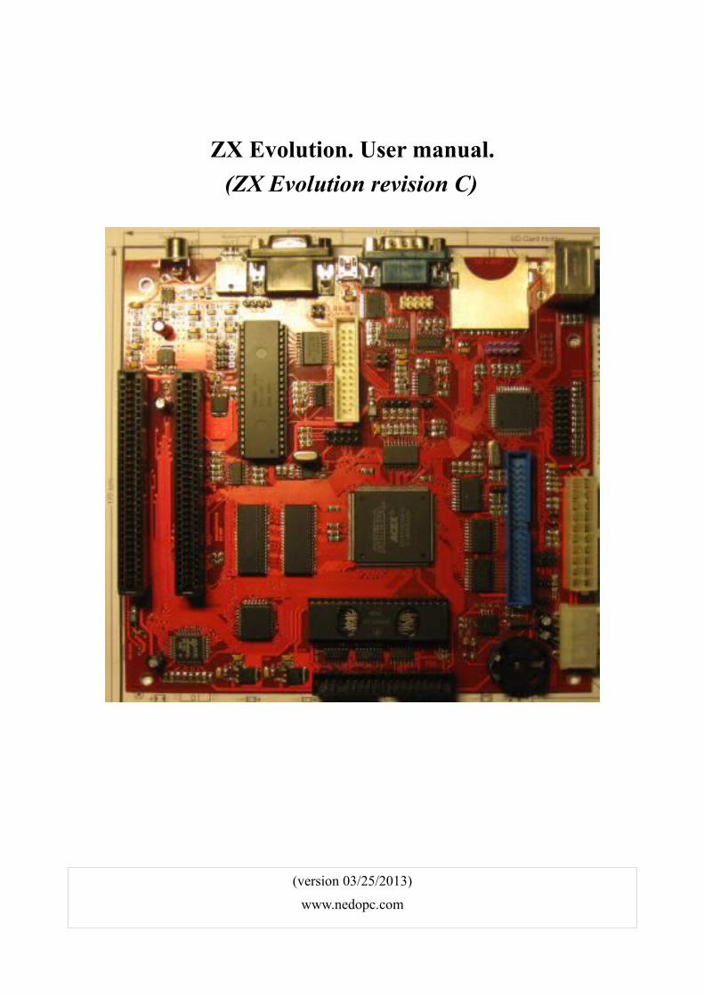
ZX Evolution. User manual.
(ZX Evolution revision C)
(version 03/25/2013)
www.nedopc.com
ZX Evolution. User manual
Table of contents 1 Introduction......................................................................................................................................3 2 Board layout.....................................................................................................................................4 3 Connectors........................................................................................................................................5
3.1 X1. Floppy disk.........................................................................................................................5 3.2 X2. IDE.....................................................................................................................................6 3.3 X3. Printer (non-full LPT)........................................................................................................6 3.4 X4. JTAG for EP1K50Q208.....................................................................................................7 3.5 X5. AVR ISP for ATMEGA128...............................................................................................7 3.6 X6. RS232 communication......................................................................................................8 3.7 X7. VGA...................................................................................................................................8 3.8 X8. RGB video out...................................................................................................................9 3.9 X9. Video out power supply.....................................................................................................9 3.10 X10. 3.5 Audio out..................................................................................................................9 3.11 X11. PS/2 keyboard and mouse..............................................................................................9 3.12 X12. Joystick and original ZX keyboard..............................................................................10
3.12.1 Using Kempston and Sinclair joysticks........................................................................10 3.13 X13. Mini USB (USB-RS232 bridge out)............................................................................11 3.14 X14. AVR JTAG for ATMEGA128......................................................................................11 3.15 X15. Tape in/out....................................................................................................................11 3.16 X16. Audio out (duplicate X10)............................................................................................11 3.17 X17, X18, X20. Audio in......................................................................................................12 3.18 X19. RS232 communication (duplicate X6).........................................................................12 3.19 X21. Tape IN (duplicate X15)..............................................................................................12 3.20 PWR1. Power........................................................................................................................12 3.21 PWR2. ATX power...............................................................................................................13 3.22 GB1. Battery holder..............................................................................................................13
4 Jumpers and button.........................................................................................................................14 5 ZXBUS slots...................................................................................................................................15 6 Installation ZX Evolution to miniITX/microATX/ATX case.........................................................17 7 ZX Evolution firmwares.................................................................................................................18 8 Appendix 1. Connecting display.....................................................................................................19 9 Appendix 2. Floppy drive...............................................................................................................20 10 Appendix 3. Additional PS2 keyboard functions (only for “baseconf” configuration and “EVO reset service” ROM).................................................21
2
ZX Evolution. User manual
1 IntroductionZX Evolution is Spectrum compatible computer. Computer based on programmable logic device Altera EP1K50Q208 and has flexible architecture, but board content original main chips (Z80, sound coprocessor, floppy controller).
ZX Evolution board designed by miniITX standard for easy installation to miniITX, mATX or ATX case.
Main features:
• Z80 on 3.5MHz (standard)/7 MHz (turbo mode) without wait circles/14MHz (mega turbo mode) with wait circles;
• 4 MBytes RAM, 512KBytes ROM (flash ROM);
• MiniITX form factor, support ATX or +5v,+12v power supply;
• 2 ZXBUS slots;
• Peripheral controller ATMEGA128;
• PS/2 keyboard/mouse interface;
• IDE interface [parallel ATA] (one channel, up to 2 devices on master/slave mode);
• SD(HC) memory card interface;
• Floppy disk interface based on WDC1793 (support up to 4 drives);
• RS232 interface;
• Integrated RS232-USB bridge;
• Realtime/Calendar (RTC);
• Sound interfaces: AY38910/YM2149F, beeper, pwm;
• Joystick and mechanical (original) keyboard interface;
• Tape interface (input/output);
• RGB video out (SCART compatible);
• VGA (scan doubler).
3
ZX Evolution. User manual
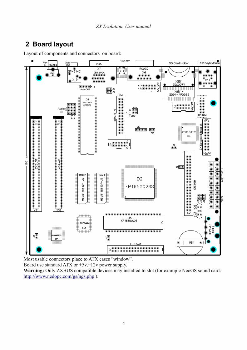
2 Board layoutLayout of components and connectors on board:
Most usable connectors place to ATX cases “window”.Board use standard ATX or +5v,+12v power supply.Warning: Only ZXBUS compatible devices may installed to slot (for example NeoGS sound card: http://www.nedopc.com/gs/ngs.php ).
4
D4
ATMEGA128
PS2 Keyb/Mouse
YM2149FAY38910
SD Card HolderVGAAudio OUT
Tape IN
Tape
IN OUT
Audio OUT
AudioIN
1s t
pin1s t
pin
ZX
Key
boar
d/Jo
ystic
k
170
mm
172 mm
ZX Evolution. User manual
3 Connectors
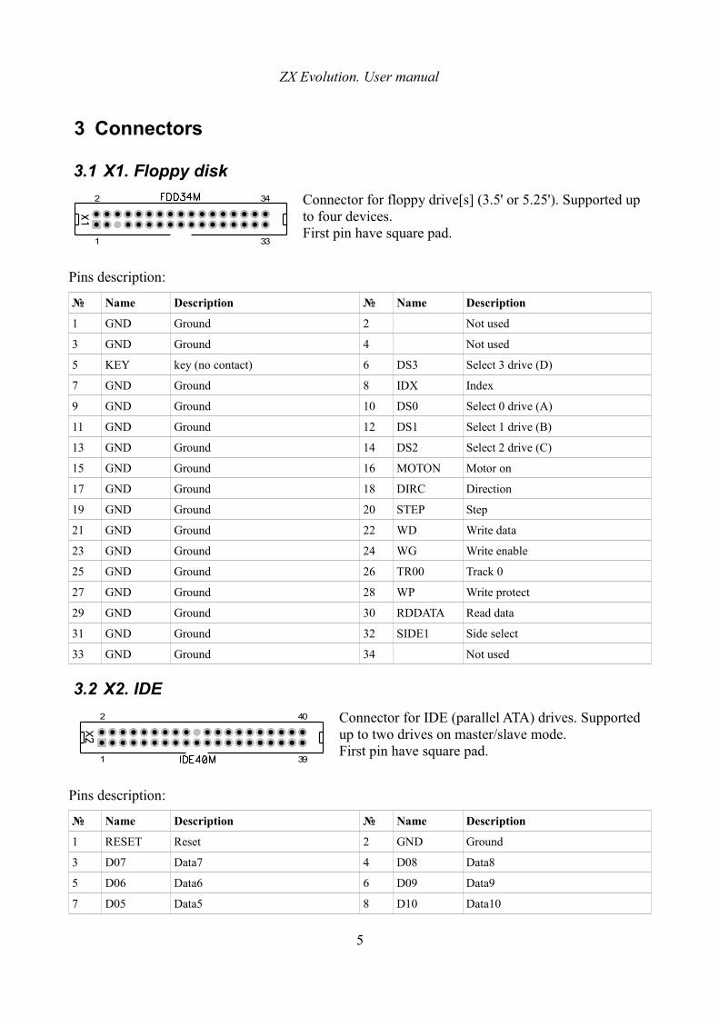
3.1 X1. Floppy disk
Connector for floppy drive[s] (3.5' or 5.25'). Supported up to four devices. First pin have square pad.
Pins description:
№ Name Description № Name Description
1 GND Ground 2 Not used
3 GND Ground 4 Not used
5 KEY key (no contact) 6 DS3 Select 3 drive (D)
7 GND Ground 8 IDX Index
9 GND Ground 10 DS0 Select 0 drive (A)
11 GND Ground 12 DS1 Select 1 drive (B)
13 GND Ground 14 DS2 Select 2 drive (C)
15 GND Ground 16 MOTON Motor on
17 GND Ground 18 DIRC Direction
19 GND Ground 20 STEP Step
21 GND Ground 22 WD Write data
23 GND Ground 24 WG Write enable
25 GND Ground 26 TR00 Track 0
27 GND Ground 28 WP Write protect
29 GND Ground 30 RDDATA Read data
31 GND Ground 32 SIDE1 Side select
33 GND Ground 34 Not used
3.2 X2. IDE
Connector for IDE (parallel ATA) drives. Supported up to two drives on master/slave mode.First pin have square pad.
Pins description:
№ Name Description № Name Description
1 RESET Reset 2 GND Ground
3 D07 Data7 4 D08 Data8
5 D06 Data6 6 D09 Data9
7 D05 Data5 8 D10 Data10
5
1
2
33
34
1 39
2 40
ZX Evolution. User manual
9 D04 Data4 10 D11 Data11
11 D03 Data3 12 D12 Data12
13 D02 Data2 14 D13 Data13
15 D01 Data1 16 D14 Data14
17 D00 Data0 18 D15 Data15
19 GND Ground 20 KEY KEY (no contact)
21 Not used 22 GND Ground
23 DIOW 24 GND Ground
25 DIOR 26 GND Ground
27 IORDY 28 Not used
29 Not used 30 GND Ground
31 Not used 32 Not used
33 DA1 Address1 34 Not used
35 DA0 Address0 36 DA2 Address1
37 CS0 Select0 38 CS1 Select
39 DASP Indicator 40 GND Ground
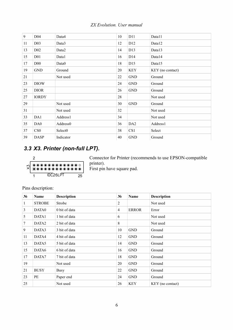
3.3 X3. Printer (non-full LPT).
Connector for Printer (recommends to use EPSON-compatible printer).First pin have square pad.
Pins description:
№ Name Description № Name Description
1 STROBE Strobe 2 Not used
3 DATA0 0 bit of data 4 ERROR Error
5 DATA1 1 bit of data 6 Not used
7 DATA2 2 bit of data 8 Not used
9 DATA3 3 bit of data 10 GND Ground
11 DATA4 4 bit of data 12 GND Ground
13 DATA5 5 bit of data 14 GND Ground
15 DATA6 6 bit of data 16 GND Ground
17 DATA7 7 bit of data 18 GND Ground
19 Not used 20 GND Ground
21 BUSY Busy 22 GND Ground
23 PE Paper end 24 GND Ground
25 Not used 26 KEY KEY (no contact)
6
1 25
2
ZX Evolution. User manual
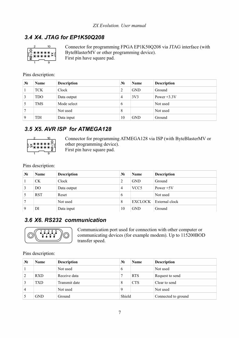
3.4 X4. JTAG for EP1K50Q208
Connector for programming FPGA EP1K50Q208 via JTAG interface (with ByteBlasterMV or other programming device).First pin have square pad.
Pins description:
№ Name Description № Name Description
1 TCK Clock 2 GND Ground
3 TDO Data output 4 3V3 Power +3.3V
5 TMS Mode select 6 Not used
7 Not used 8 Not used
9 TDI Data input 10 GND Ground
3.5 X5. AVR ISP for ATMEGA128
Connector for programming ATMEGA128 via ISP (with ByteBlasterMV or other programming device).First pin have square pad.
Pins description:
№ Name Description № Name Description
1 CK Clock 2 GND Ground
3 DO Data output 4 VCC5 Power +5V
5 RST Reset 6 Not used
7 Not used 8 EXCLOCK External clock
9 DI Data input 10 GND Ground
3.6 X6. RS232 communication
Communication port used for connection with other computer or communicating devices (for example modem). Up to 115200BOD transfer speed.
Pins description:
№ Name Description № Name Description
1 Not used 6 Not used
2 RXD Receive data 7 RTS Request to send
3 TXD Transmit date 8 CTS Clear to send
4 Not used 9 Not used
5 GND Ground Shield Connected to ground
7
1 9
2 10
1 9
2 10
51 2 3 46 7 8 9
ZX Evolution. User manual
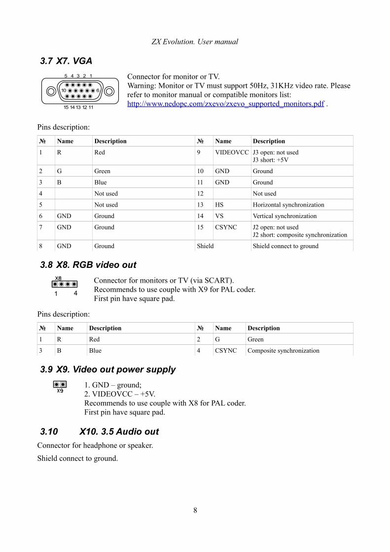
3.7 X7. VGA
Connector for monitor or TV.Warning: Monitor or TV must support 50Hz, 31KHz video rate. Please refer to monitor manual or compatible monitors list: http://www.nedopc.com/zxevo/zxevo_supported_monitors.pdf .
Pins description:
№ Name Description № Name Description
1 R Red 9 VIDEOVCC J3 open: not usedJ3 short: +5V
2 G Green 10 GND Ground
3 B Blue 11 GND Ground
4 Not used 12 Not used
5 Not used 13 HS Horizontal synchronization
6 GND Ground 14 VS Vertical synchronization
7 GND Ground 15 CSYNC J2 open: not usedJ2 short: composite synchronization
8 GND Ground Shield Shield connect to ground
3.8 X8. RGB video out
Connector for monitors or TV (via SCART). Recommends to use couple with X9 for PAL coder.First pin have square pad.
Pins description:
№ Name Description № Name Description
1 R Red 2 G Green
3 B Blue 4 CSYNC Composite synchronization
3.9 X9. Video out power supply
1. GND – ground;2. VIDEOVCC – +5V.Recommends to use couple with X8 for PAL coder.First pin have square pad.
3.10 X10. 3.5 Audio out
Connector for headphone or speaker.
Shield connect to ground.
8
5 1234
15 11121314
10 6
1 4
ZX Evolution. User manual
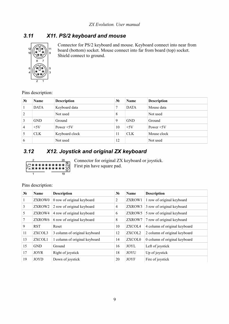
3.11 X11. PS/2 keyboard and mouse
Connector for PS/2 keyboard and mouse. Keyboard connect into near from board (bottom) socket. Mouse connect into far from board (top) socket. Shield connect to ground.
Pins description:
№ Name Description № Name Description
1 DATA Keyboard data 7 DATA Mouse data
2 Not used 8 Not used
3 GND Ground 9 GND Ground
4 +5V Power +5V 10 +5V Power +5V
5 CLK Keyboard clock 11 CLK Mouse clock
6 Not used 12 Not used
3.12 X12. Joystick and original ZX keyboard
Connector for original ZX keyboard or joystick.First pin have square pad.
Pins description:
№ Name Description № Name Description
1 ZXROW0 0 row of original keyboard 2 ZXROW1 1 row of original keyboard
3 ZXROW2 2 row of original keyboard 4 ZXROW3 3 row of original keyboard
5 ZXROW4 4 row of original keyboard 6 ZXROW5 5 row of original keyboard
7 ZXROW6 6 row of original keyboard 8 ZXROW7 7 row of original keyboard
9 RST Reset 10 ZXCOL4 4 column of original keyboard
11 ZXCOL3 3 column of original keyboard 12 ZXCOL2 2 column of original keyboard
13 ZXCOL1 1 column of original keyboard 14 ZXCOL0 0 column of original keyboard
15 GND Ground 16 JOYL Left of joystick
17 JOYR Right of joystick 18 JOYU Up of joystick
19 JOYD Down of joystick 20 JOYF Fire of joystick
9
4
2 1
6
3
5
8 7
9
11
10
12
1 19
2 20
ZX Evolution. User manual
3.12.1 Using Kempston and Sinclair joysticks
Sinclair 1 Sinclair 2 Kempston
Function ZX keyboard
button
X12shorted pins
Function ZX keyboard
button
X12shorted pins
Function X12shorted pins
left 1 4 - 14 left 6 5 - 10 left 15 - 16
right 2 4 - 13 right 7 5 - 11 right 15 - 17
down 3 4 - 12 down 8 5 - 12 up 15 - 18
up 4 4 - 11 up 9 5 - 13 down 15 - 19
fire 5 4 - 10 fire 0 5 - 14 fire 15 - 20
3.13 X13. Mini USB (USB-RS232 bridge out)
For connecting to other computer in USB-slave mode.
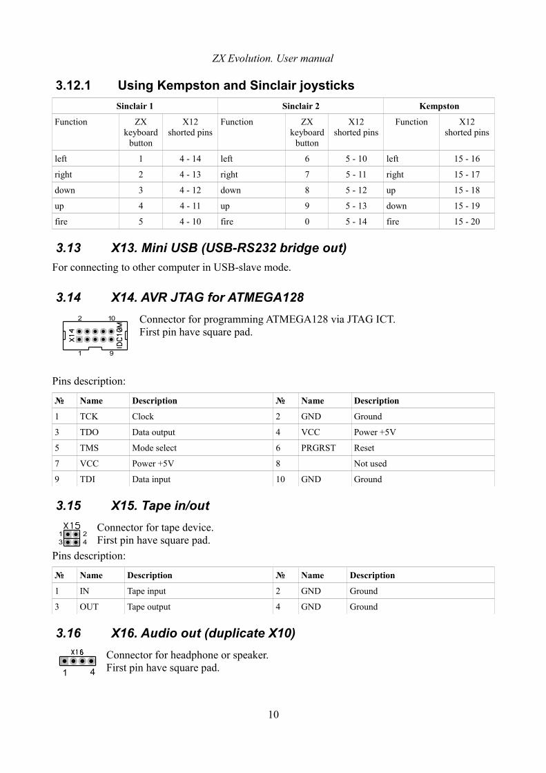
3.14 X14. AVR JTAG for ATMEGA128
Connector for programming ATMEGA128 via JTAG ICT.First pin have square pad.
Pins description:
№ Name Description № Name Description
1 TCK Clock 2 GND Ground
3 TDO Data output 4 VCC Power +5V
5 TMS Mode select 6 PRGRST Reset
7 VCC Power +5V 8 Not used
9 TDI Data input 10 GND Ground
3.15 X15. Tape in/out
Connector for tape device.First pin have square pad.
Pins description:
№ Name Description № Name Description
1 IN Tape input 2 GND Ground
3 OUT Tape output 4 GND Ground
3.16 X16. Audio out (duplicate X10)
Connector for headphone or speaker.First pin have square pad.
10
1 9
2 10
24
13
1 4
ZX Evolution. User manual
Pins description:
№ Name Description № Name Description
1 LOUT Left 2 GND Ground
3 GND Ground 4 ROUT Right
3.17 X17, X18, X20. Audio in
Connector for external audio sources (for example CDROM, NeoGS, TurboSound).First pin have square pad.
Pins description:
№ Name Description № Name Description
1 LIN Left 2 GND Ground
3 GND Ground 4 RIN Right
3.18 X19. RS232 communication (duplicate X6)
Communication port used for connection with other computer or communicating devices (for example modem). Up to 115200BOD transfer speed.First pin have square pad.
Pins description:
№ Name Description № Name Description
1 Not used 2 RXD Receive data
3 TXD Transmit data 4 Not used
5 GND Ground 6 Not used
7 RTS Request to send 8 CTS Clear to send
9 Not used 10 VCC +5V
3.19 X21. Tape IN (duplicate X15)
For connecting tape device.
3.20 PWR1. Power
Connector for non-standard power supply (+12V, +5V, GND).
Pins description:
№ Name Description № Name Description
11
1 2 3 4
2 10
1 9
1234
ZX Evolution. User manual
1 VCC5 Power +5V 3 GND Ground
2 GND Ground 4 VCC12 Power +12V
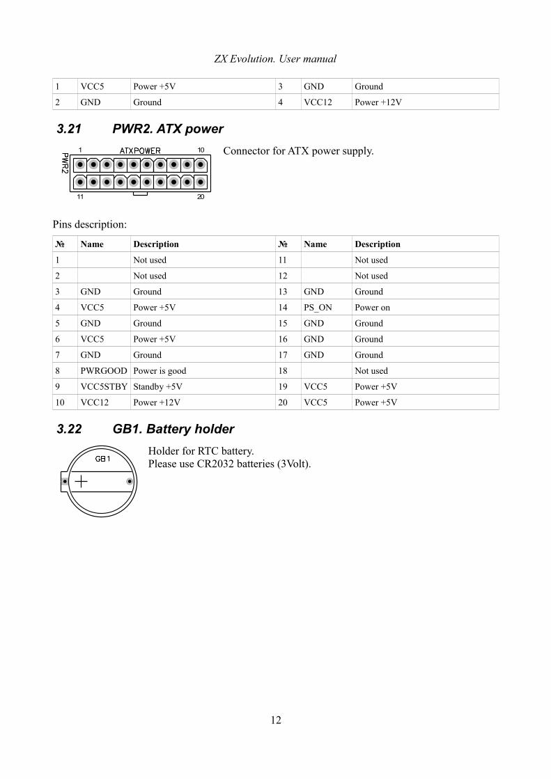
3.21 PWR2. ATX power
Connector for ATX power supply.
Pins description:
№ Name Description № Name Description
1 Not used 11 Not used
2 Not used 12 Not used
3 GND Ground 13 GND Ground
4 VCC5 Power +5V 14 PS_ON Power on
5 GND Ground 15 GND Ground
6 VCC5 Power +5V 16 GND Ground
7 GND Ground 17 GND Ground
8 PWRGOOD Power is good 18 Not used
9 VCC5STBY Standby +5V 19 VCC5 Power +5V
10 VCC12 Power +12V 20 VCC5 Power +5V
3.22 GB1. Battery holder
Holder for RTC battery.Please use CR2032 batteries (3Volt).
12
1 10
11 20
ZX Evolution. User manual
4 Jumpers and button
№ Name Default value Description
J1 enable IDERES
opened Enable IDE reset signal to IDE drives if shorted. It need to some old drives (for example Samsung 10Gb drives).
J2 enable composite sync to VGA
opened Enable composite synchronization to VGA if shorted.
J3 enable +5V to VGA
opened Enable +5V to VGA if shorted.
J4 12v enable opened Enable +12V power supply to slots if shorted.
J5 external clock
opened Enable external clock to ATMEGA128 from AVR ISP connector (X5).
J6 soft reset key
opened Soft reset or power switching:- connect «PWR SW» button from ATX case;- soft reset (without restart ATMEGA128) if shorted few time.
J7 HRDY->IP opened HRDY controlled IP pull-down to GND if closed.
J8 NMI key opened Set NMI to Z80 if shorted.
J9 hard reset key
opened Hard reset (with restart ATMEGA128) if shorted.Connect «Reset» button of AT or ATX case.
VD31 HDD Led Connect «HDD LED» from AT or ATX case.
VD62 PWR Led Connect «PWR LED» from AT or ATX case.
1 If set contacts instead VD3 led on board (for example boards from NedoPC).2 If set contacts instead VD6 led on board (for example boards from NedoPC).
13
ZX Evolution. User manual
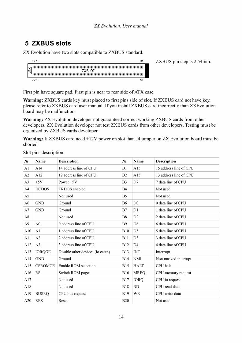
5 ZXBUS slotsZX Evolution have two slots compatible to ZXBUS standard.
ZXBUS pin step is 2.54mm.
First pin have square pad. First pin is near to rear side of ATX case.
Warning: ZXBUS cards key must placed to first pins side of slot. If ZXBUS card not have key, please refer to ZXBUS card user manual. If you install ZXBUS card incorrectly than ZXEvolution board may be malfunction.
Warning: ZX Evolution developer not guaranteed correct working ZXBUS cards from other developers. ZX Evolution developer not test ZXBUS cards from other developers. Testing must be organized by ZXBUS cards developer.
Warning: If ZXBUS card need +12V power on slot than J4 jumper on ZX Evolution board must be shorted.
Slot pins description:
№ Name Description № Name Description
A1 A14 14 address line of CPU B1 A15 15 address line of CPU
A2 A12 12 address line of CPU B2 A13 13 address line of CPU
A3 +5V Power +5V B3 D7 7 data line of CPU
A4 DCDOS TRDOS enabled B4 Not used
A5 Not used B5 Not used
A6 GND Ground B6 D0 0 data line of CPU
A7 GND Ground B7 D1 1 data line of CPU
A8 Not used B8 D2 2 data line of CPU
A9 A0 0 address line of CPU B9 D6 6 data line of CPU
A10 A1 1 address line of CPU B10 D5 5 data line of CPU
A11 A2 2 address line of CPU B11 D3 3 data line of CPU
A12 A3 3 address line of CPU B12 D4 4 data line of CPU
A13 IORQGE Disable other devices (io catch) B13 INT Interrupt
A14 GND Ground B14 NMI Non masked interrupt
A15 CSROMCE Enable ROM selection B15 HALT CPU halt
A16 RS Switch ROM pages B16 MREQ CPU memory request
A17 Not used B17 IORQ CPU io request
A18 Not used B18 RD CPU read data
A19 BUSRQ CPU bus request B19 WR CPU write data
A20 RES Reset B20 Not used
14
B1B31
A1A31
ZX Evolution. User manual
A21 A7 7 address line of CPU B21 WAIT CPU wait
A22 A6 6 address line of CPU B22 Not used
A23 A5 5 address line of CPU B23 Not used
A24 A4 4 address line of CPU B24 M1 M1 state of CPU
A25 CSROM ROM selected B25 RFSH Refresh
A26 BUSAK CPU bus acknowledge B26 A8 8 address line of CPU
A27 A9 9 address line of CPU B27 A10 10 address line of CPU
A28 A11 11 address line of CPU B28 +5V Power +5V
A29 +5V Power +5V B29 +12V Power +12V
A30 GND Ground B30 GND Ground
A31 On XS1: IORQGE2On XS2: not used
B31 On XS1: IORQ2On XS2: not used
15
ZX Evolution. User manual
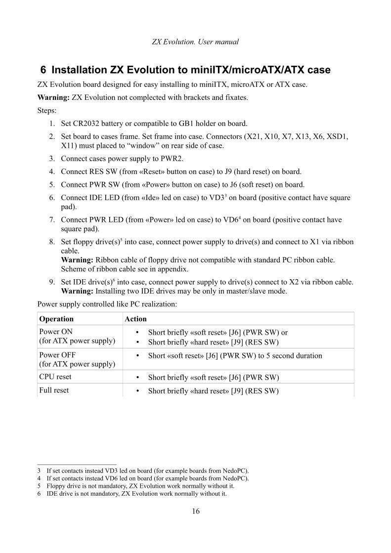
6 Installation ZX Evolution to miniITX/microATX/ATX caseZX Evolution board designed for easy installing to miniITX, microATX or ATX case.
Warning: ZX Evolution not complected with brackets and fixates.
Steps:
1. Set CR2032 battery or compatible to GB1 holder on board.
2. Set board to cases frame. Set frame into case. Connectors (X21, X10, X7, X13, X6, XSD1, X11) must placed to “window” on rear side of case.
3. Connect cases power supply to PWR2.
4. Connect RES SW (from «Reset» button on case) to J9 (hard reset) on board.
5. Connect PWR SW (from «Power» button on case) to J6 (soft reset) on board.
6. Connect IDE LED (from «Ide» led on case) to VD33 on board (positive contact have square pad).
7. Connect PWR LED (from «Power» led on case) to VD64 on board (positive contact have square pad).
8. Set floppy drive(s)5 into case, connect power supply to drive(s) and connect to X1 via ribbon cable.Warning: Ribbon cable of floppy drive not compatible with standard PC ribbon cable. Scheme of ribbon cable see in appendix.
9. Set IDE drive(s)6 into case, connect power supply to drive(s) connect to X2 via ribbon cable.Warning: Installing two IDE drives may be only in master/slave mode.
Power supply controlled like PC realization:
Operation Action
Power ON(for ATX power supply)
• Short briefly «soft reset» [J6] (PWR SW) or• Short briefly «hard reset» [J9] (RES SW)
Power OFF(for ATX power supply)
• Short «soft reset» [J6] (PWR SW) to 5 second duration
CPU reset • Short briefly «soft reset» [J6] (PWR SW)
Full reset • Short briefly «hard reset» [J9] (RES SW)
3 If set contacts instead VD3 led on board (for example boards from NedoPC).4 If set contacts instead VD6 led on board (for example boards from NedoPC).5 Floppy drive is not mandatory, ZX Evolution work normally without it.6 IDE drive is not mandatory, ZX Evolution work normally without it.
16
ZX Evolution. User manual
7 ZX Evolution firmwaresZX Evolution content MCU ATMEGA128 and EPROM 29F040.
MCU ATMEGA128 is next functionality:
• Control peripheral devices, convert interfaces to ZX Spectrum standarts;
• Load configuration to EP1K50QC208 on power up or «hardware» reset of ZX Evolution;
• Update firmwares.
Firmware ATMEGA128 content two parts:
• BOOTLOADER – non-modified part for update or modify other firmware part of MCU (see documentation of bootloader7). This part flashed by special MCU-programmer device. You can update bootloader on new release only via special MCU-programmer device.
• Configuration – part, whose control peripheral devices and load EP1K50QC208. Some developers can to create different configurations. Exist service configuration for tuning and testing ZX Evolution board. Configurations stores in special file zxevo_fw.bin .
Warning: NedoPC support two configurations:
• TEST&SERVICE – configuration for tuning and testing ZX Evolution after soldering. This configuration can flash EPROM 29F040;
• BASECONF – base configuration. This configuration is base and example for ZX Evolution. Base configuration developed by NedoPC. Other developers can use source of base configuration like example for own configurations.
Warning: NedoPC not support configurations from other developers and not guaranteed correct functionality of ZX Evolution.
EPROM 29F040 content Z80 subprograms for working ZX Evolution in ZX Spectrum mode (Basic48, Basic128, TRDOS and etc). Flashing image stored in binary file zxevo.rom (size of image must correspond size of EPROM 29F040). Other developers may arrange of EPROMs content on own needs.
You can use TEST&SERVICE configuration for flashing or updating EPROM:
• Upload TEST&SERVICE configuration to ZX Evolution via BOOTLOADER;
• Copy zxevo.rom to SD memory card and set it on ZX Evolution;
• Select “update” menu in TEST&SERVICE configuration and flash EPROM;
• Upload working configuration (for example BASECONF) via BOOTLOADER to ZX Evolution.
Warning: NedoPC version of EPROM image based on EVO RESET SERVICE. This version of EPROM used in couple with BASECONF configuration from NedoPC. Updating new version BASECONF and EPROM image recommend in same time, cause new version of BASECONF may not work with old version of EPROM and vise verse. EVO RESET SERVICE can update EPROM in itself (see documentation).
7 http://www.nedopc.com/zxevo/rom/zxevo_firmware_update_eng.pdf
17
ZX Evolution. User manual
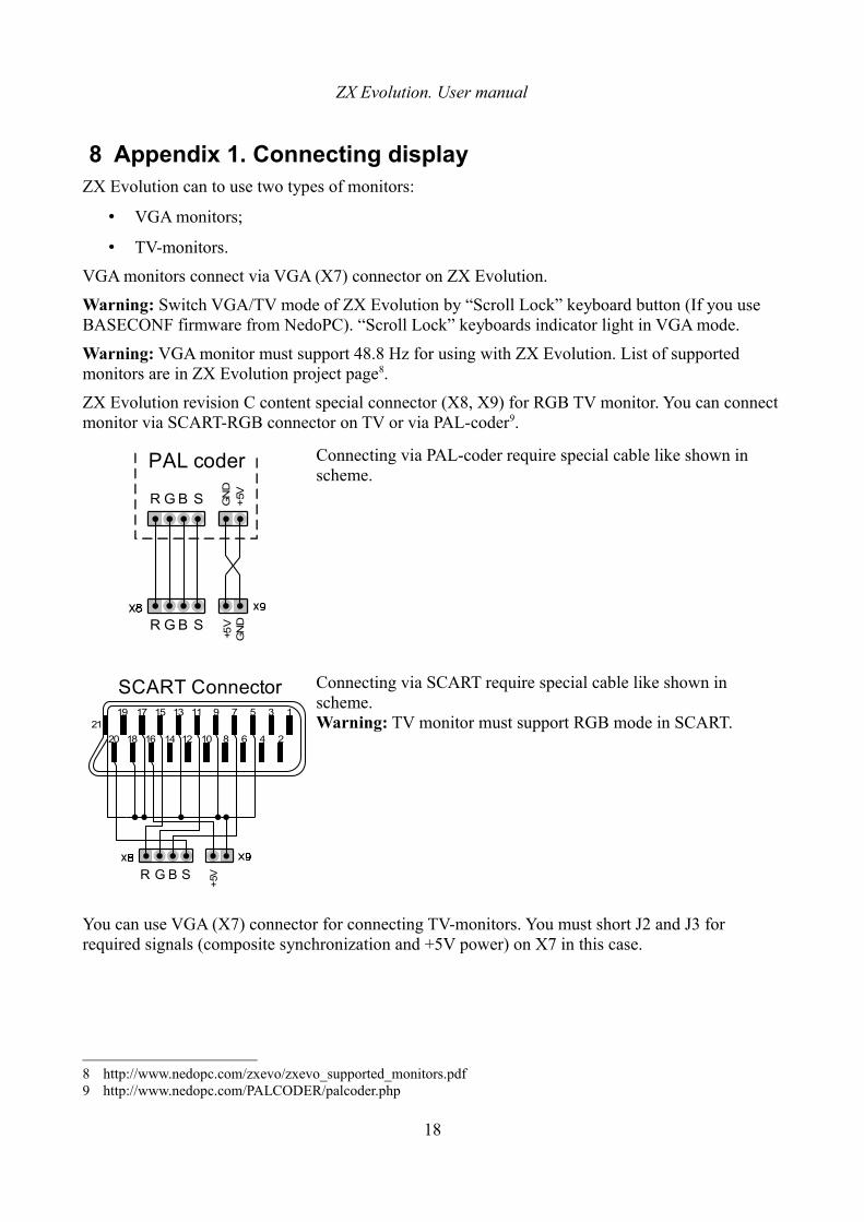
8 Appendix 1. Connecting displayZX Evolution can to use two types of monitors:
• VGA monitors;
• TV-monitors.
VGA monitors connect via VGA (X7) connector on ZX Evolution.
Warning: Switch VGA/TV mode of ZX Evolution by “Scroll Lock” keyboard button (If you use BASECONF firmware from NedoPC). “Scroll Lock” keyboards indicator light in VGA mode.
Warning: VGA monitor must support 48.8 Hz for using with ZX Evolution. List of supported monitors are in ZX Evolution project page8.
ZX Evolution revision С content special connector (X8, X9) for RGB TV monitor. You can connect monitor via SCART-RGB connector on TV or via PAL-coder9.
Connecting via PAL-coder require special cable like shown in scheme.
Connecting via SCART require special cable like shown in scheme.Warning: TV monitor must support RGB mode in SCART.
You can use VGA (X7) connector for connecting TV-monitors. You must short J2 and J3 for required signals (composite synchronization and +5V power) on X7 in this case.
8 http://www.nedopc.com/zxevo/zxevo_supported_monitors.pdf9 http://www.nedopc.com/PALCODER/palcoder.php
18
R G B S
+5V
2119 17 15 13 11 9 7 5 3 1
2468101214161820
SCART Connector
R G B S
+5V
GN
D
R G B S +5V
GN
D
PAL coder
ZX Evolution. User manual
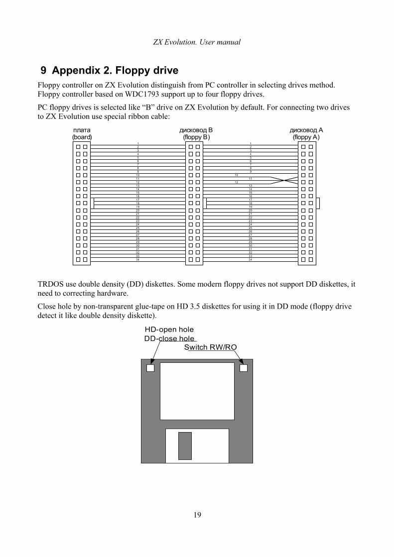
9 Appendix 2. Floppy driveFloppy controller on ZX Evolution distinguish from PC controller in selecting drives method. Floppy controller based on WDC1793 support up to four floppy drives.
PC floppy drives is selected like “B” drive on ZX Evolution by default. For connecting two drives to ZX Evolution use special ribbon cable:
TRDOS use double density (DD) diskettes. Some modern floppy drives not support DD diskettes, it need to correcting hardware.
Close hole by non-transparent glue-tape on HD 3.5 diskettes for using it in DD mode (floppy drive detect it like double density diskette).
19
123456789
10111213141516171819202122232425262728293031323334
123456789
1011
1213141516171819202122232425262728293031323334
плата(board)
дисковод A(floppy A)
дисковод B(floppy B)
Switch RW/RO
HD-open holeDD-close hole
ZX Evolution. User manual
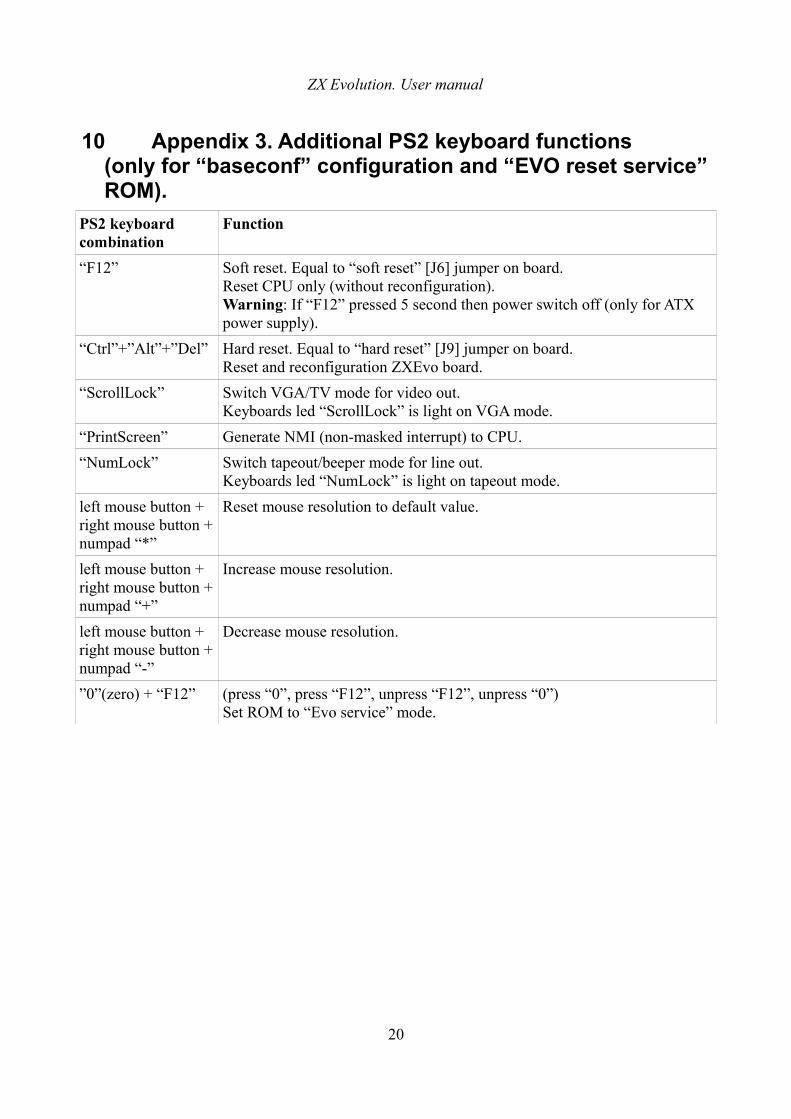
10 Appendix 3. Additional PS2 keyboard functions (only for “baseconf” configuration and “EVO reset service” ROM).
PS2 keyboard combination
Function
“F12” Soft reset. Equal to “soft reset” [J6] jumper on board.Reset CPU only (without reconfiguration). Warning: If “F12” pressed 5 second then power switch off (only for ATX power supply).
“Ctrl”+”Alt”+”Del” Hard reset. Equal to “hard reset” [J9] jumper on board.Reset and reconfiguration ZXEvo board.
“ScrollLock” Switch VGA/TV mode for video out. Keyboards led “ScrollLock” is light on VGA mode.
“PrintScreen” Generate NMI (non-masked interrupt) to CPU.
“NumLock” Switch tapeout/beeper mode for line out. Keyboards led “NumLock” is light on tapeout mode.
left mouse button + right mouse button +numpad “*”
Reset mouse resolution to default value.
left mouse button + right mouse button +numpad “+”
Increase mouse resolution.
left mouse button + right mouse button +numpad “-”
Decrease mouse resolution.
”0”(zero) + “F12” (press “0”, press “F12”, unpress “F12”, unpress “0”)Set ROM to “Evo service” mode.
20


![[ZX] Changement d'un joint de culasse sur une ZX 1xud9te.free.fr/Download/Tutorial/[ZX]Changement_joint... · 2008. 11. 30. · [ZX] Changement d'un joint de culasse sur une ZX 1.9D](https://img.dokumen.tips/doc/110x75/60d4a95281e5cb60cf64541b/zx-changement-dun-joint-de-culasse-sur-une-zx-zxchangementjoint-2008.jpg)