Embed Size (px)
Citation preview

Page �
ZX-14 Stage I Turbo Kit
WARNING: This turbo kit is for OFF-ROAD RACING use ONLY.
Advisement: These instructions are written to be comprehensive and detailed to make the installation of this kit go as smoothly as possible. However, the installation of the Muzzys ZX-14 Turbo kit is an extensive and complex task. No instructions can be a substitute for the mechanical experience necessary to properly complete this project. Therefore, if after reviewing this document you have any doubts about your skills or experience we strongly urge you to seek professional assistance. Note that these instructions are written in the sequence that the assembly must be done. Deviation from this order will result in extra work from having to backtrack.
1 ToolsandSuppliesIn addition to the normal tools required for service and maintenance you will need to have the following items on hand to complete the Street Turbo installation in a professional manner.q High temperature gasket sealer (Permatex Ultra Grey recommended).q Silicon sealer (such as Permatex Black).q General purpose grease (Non-moly type).q Pipe thread sealer, Teflon paste type (Loctite PST 592 recommended).q Spray penetrating lubricant (such as WD-40).q Brake or contact cleaner, spray type.q Thread locker, non-permanent (such as Loctite 242).q A 7/32” drill bit and drill.q An assortment of cable ties (zip ties).q A heatgun. q A source of compressed air.q Anti seize q Safety Wire
2 BikePreparationThe following items will need to be addressed in order to prepare your ZX14 for the Stage I Turbo kit installation. Please refer to your Kawasaki service manual for further information.q Remove the following bodywork: Tank front coverSeatSide FairingLower FairingLower Rear Cowlq Drain and remove the fuel tank. q Drain the cooling system into a clean container so that it can be reused. (This is best done from the
drain bolt in the water pump housing, open the filler cap to vent while draining.) Remember that coolant is poisonous. Be sure to keep it away from pets and children and store it in a clearly marked and sealed container.
q Remove the radiator.
62910 Peerless Ct. • Bend, OR 97701 Phone 541.385.0706 Fax 541.382.9406

Page �
q Remove the exhaust system.q Remove the air box lids and rear inlet tubes.q Drain the oil and remove the oil filter. q Remove the crankcase breather line from the frame (left hand side behind the throttle bodies) and plug
this inlet with the provided rubber cap and clamp.(photo 2)q Remove the oil water trap line and install an 8 x 16mm allen bolt and washer. (photo 2)q Remove the oil sender unit (on oil pan).q Remove the upper radiator shroud (attached to engine). This will be modified later to accomodate the 2”
air inlet pipe. q Remove the secondary butterflies. (photo 1) 1. Heat the screws on each plate using a heat gun on medium heat. 2. Remove the screws and plates. (DO NOT OPEN THE THROTTLE DURING REMOVAL!)
4. TurboMounting
q Exhaust Manifold (photo 4)ØScrape off any carbon deposits from the exhaust port sealing surface, clean with brake cleaner and
wipe dry. Also clean any packing residue from the sealing surfaces of the turbo manifold (both the exhaust port side and turbo mounting flange).
ØInstall new copper exhaust gaskets into the exhaust ports. Use a light coating of high temperature sealer to hold the seals in place.
ØInstall the exhaust manifold onto the exhaust ports. The fit is intentionally tight to ensure the best seal possible so make sure you have the alignment correct. Working from side to side fit the manifold flange onto the studs. You may need a soft mallet (plastic or rubber) to get things started but use it only on the flange, not on the manifold. The manifold ends will be guided into the ports. Be sure the gaskets have stayed in place.
ØOnce sufficient threads are through the manifold flange install the new locking exhaust nuts and use them to pull the manifold into final position. Work gradually and side to side to ensure the manifold is seated squarely in the ports.
ØWorking from the center out final torque the nuts. Since the process will be crushing the copper seals you may need to go through the final torqueing more than once. For the best, most long lasting seal you need have the manifold seated squarely and all the nuts torqued evenly.
q Hanging the Turbo Assembly (photo 3 & 4)The turbo assembly is comprised of three main sections: turbine housing, bearing housing (w/ oil inlet and outlet) and the compressor housing. The three sections are joined on sliding mating surfaces secured by lock plates and pinch bolts. ØLoosen the pinch bolts on both the turbine and compressor housings just enough to allow free
rotation. Rotate the housings so that the turbine inlet, oil inlet (w/ screened fitting) and compressor outlet all point roughly the same direction.
ØClean the mounting flange of the turbine housing of any protective coating. Gather the following hardware and put it close at hand:◊ The rectangular metal turbine gasket.◊ The four M10 x 35mm mounting bolts with matching nuts and washers.
ØMate the turbo assembly to the manifold. (Fig. 4) Hopefully you have an assistant to help hold the turbo. Be prepared for a bit of a challenge if you’re working by yourself. Note the following:◊ The compressor is on the right side of the bike, the turbine will exhaust to the left. ◊ The gasket goes in between the turbine and manifold flanges. It is coated with a dry sealer but
you may use a light coating of high temperature sealer to help hold it in place. ◊ The bolts go in from the top, nuts are on the bottom and there are washers used. The bolts need
only to be hand tight at first. Use anti-seize on the threads. Remember you can still rotate the

Page �
bearing and compressor housings to help access the bolts in the following steps. ØFinal tighten the 10mm turbo flange bolts.
q Bearing Housing AdjustmentØRotate the bearing housing forward and screw the –3AN to 1/8” NPT 90˚ fitting into the screened
fitting using the proper amount of pipe thread sealer. You should end with the fitting pointing back towards the engine. Do not over-tighten.
ØInstall the 3/8” NPT to -8 straight fitting into the oil outlet adapter using pipe thread sealer. The fitting will point to the rear when installed. (photo 7)
ØClean the oil outlet flange on the bottom of the bearing housing. ØBolt the oil outlet adapter to the bottom of the bearing housing using the composite gasket and the
two M8 x 20mm bolts. The fitting should point back towards the engine. The gasket requires no sealer but if it makes you feel better use a little high temperature sealer. (photo 11)
ØRotate the bearing housing so that the inlet and outlet are roughly straight up and down. Then tighten the pinch bolts going into the turbine housing. Don’t overdo it, the bolts tend to tighten up with the high heat of the turbo and you may regret it someday if they’re over-tightened.
ØLeave the compressor housing free to rotate (it should now be pointing up and to the rear) until we install the compressor pipe in a later section.
5. Mountingthepipe&wastegateØThe two wastegate mounting flanges form an “L”. Using the two composite gaskets, four 8 x 20mm
bolts and exhaust seat, install the wastegate using antiseize on the bolts. Tighten all four bolts evenly. (photo 5)
ØMake sure the turbo flange and pipe flange are clean then apply high temperature silicon sealer to the flange and install using the (5) 8 x 20mm allen bolts and tighten completely. (photo 4 & 5)
ØNext install the 90˚ -4 to 1/8” npt into the main housing on the wasegate -- NOT THE CAP. (photo 4)
ØInstall the other 90˚ -4 to 1/8” npt into the compressor housing. (photo 3) ØCut two 4” sections of fire sleeve and slide them over the 1/2” blue high pressure line. ØInstall the 90˚ Push-Lok hose end on one end of the 1/2” line then connect it to the wastegate fitting.
(photo 4)ØRoute the hose up and over the radiator and install the straight Push-Lok fitting then connect it to the
90˚ fitting on the compressor housing. (photo 3 & 22)ØNow that both ends of the hose are connected, carefully position each fire sleeve on the hose so that
it protects the areas of the hose closest to the exhaust manifold. Secure each section with safety wire. (photo 4 & 22)
5. MountingthescavengepumpØLocate (5) 6mm flathead allen bolts. Four are used to mount the pump and the other is for mounting
the one way valve.ØMount the pump (photo 8 & 9) to the bracket using four 6mm flat head allen bolts by pushing them
through the rubber grommets from the top side of the bracket. Secure and tighten the bolts using the fender washers and locknuts.
ØNext install the remaining allen bolt through the last countersunk hole. Secure with a washer and regular nut. This bolt will mount the one way valve later.
ØMount the pump bracket to the rear of the oil pan using (8) 6 x 30mm allen bolts. (NOTE: the three holes without raised bosses are for stock fairing mounts. (photos 8, 9 & 15)
5. WiringthescavengepumpØRemove the rubber boot from the rear of the scavenge pump. Note the polarity +/- of the two wire
connetors on the back of the pump. ØInsert each lead of the short two wire pigtail through each hole of the rubber scavenge pump boot.ØInstall and crimp one flat female spade connector onto each lead, then connect the leads to the pump
connectors (NOTE: The black lead connects to negative (-) and the red to positive (+)).

Page �
ØRe-install the rubber boot over the scavenge pump. (photo 9)ØMount the scavenge pump harness relay next to the battery. There is a revnut at the rear of the
battery box that may be used for mounting. (photo 10)ØConnect the positive and negative leads to the battery. (photo 9)ØRoute the long lead down between the swing arm and frame toward the scavenge pump. ØPlug this lead into the scavenge pump plug (photo 9).ØThe other lead goes toward the rear of the bike on the left hand side and plugs inline of the fuel
pump plug. (photo 6)5. Plumbingthescavengepump
ØUsing thread sealer, install the 3/8” npt to hose barb fittings (male and female) onto each end of the gold one way valve. (photo 12)
ØInstall a straight -8 to hose barb onto the oil drain of the turbo. Push the 1/2” hose onto the barb and cut to 3”. (photo 11)
ØNow install the one way valve assembly onto the 3” hose so the arrow points toward the scavenge pump. (NOTE - The ARROW on this valve must POINT TOWARD THE SCAVENGE PUMP) (photo 12)
ØCut another 3” section of 1/2” hose and install this onto the other end of the one way valve. Install a straight -8 hose barb onto the inlet of the pump and install the open end of the 3” hose onto it. (photo 8)
ØInstall a 90˚ -8 hose end on the other side of the pump and push the 1/2 hose onto it. Route the hose up between the right footpeg mount and the swing arm. Continue over the top of the swing arm up to where the oil filler plug used to go. The new billet oil filler plug has a -8 swivel screwed into it. Install another -8 90˚ hose end onto -8 swivel. (photo 13)
ØTrim the 1/2” hose to fit and insert it into the -8 90˚ hose barb. (photo 13) ØTighten all -8 hose ends.
6. Mountingandconnectingtheoilsystem:(usethreadsealeronallthreads)ØUsing thread sealer, install a -3 straight to 1/8”npt into each end of the small one way valve. Tighten
both ends. (photo 8)ØInstall the 1/8” npt male end of the “T” fitting into the female end of the 1/8” male to female adaptor.ØNext install the -3 90˚ to 1/8” npt onto one end of the “T” fitting. (Do not tighten yet) (photo 14)ØInstall the “T” fitting assembly into the port where you removed the oil pressure sending unit. When
tight, the top of this fitting assembly will be pointed slightly to the left of the bike to allow proper oil filter clearance. (photo xxx) The 90˚ fitting will be toward the bottom of the assembly. (photo 14)
ØInstall the oil pressure sending unit in the top of the “T” (photo 14)ØConnect the 45˚ end of the short -3 hose to the -3 90˚ fitting. (photo 14) ØRoute this line beside the oil pan and connect it to the small one way valve. (NOTE - This line will
run oil from the engine to the turbo. The flow of oil will go toward the turbo and the ARROW on the one way valve must POINT TOWARD THE TURBO) (photo 15)
ØConnect the 90˚ end of the remaining -3 line to the other end of the one way valve. Connect the 45˚ end to the -3 90˚ fitting installed earlier at the turbo oil inlet . (photo 7)
ØMake sure all lines are tight.ØSecure the small one way valve using the 5/8” clamp and mounting it with a locknut to the 6mm
bolt on the bottom of the scavenge pump mounting bracket. (photo 8)7. RemovetheCleanAirsystem.Thisincludes:
ØRemove the Clean Air system hose from the right underside of the frame. ØRemove the reed valve cover plates and install the Muzzys billet covers according to the directions
with the kit. Note that you will not use the gaskets provided in the kit nor will you remove the OEM reeds. On the ZX14 the gasket is part of the reed plate and the complete assembly is needed for a proper seal.
8. Installingframeblock-offplates

Page �
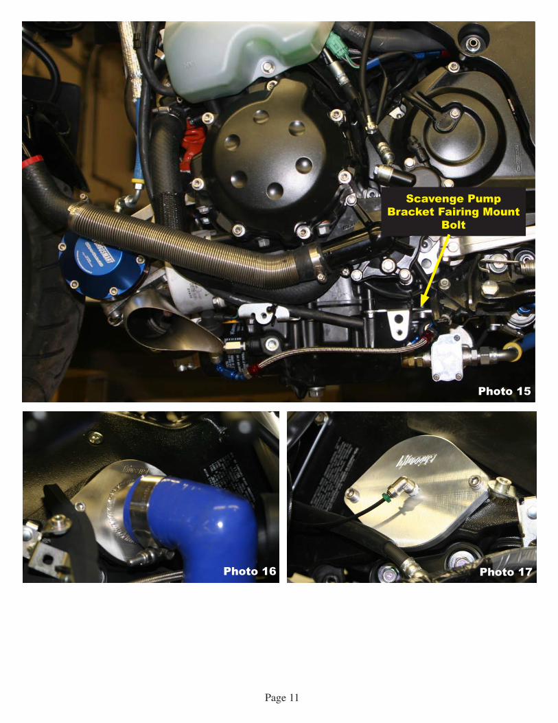
ØMount the inlet plate and O-ring on the right side of the frame. (photo 16)ØMount the air filter plate, left block off plate and O-rings on the left side of the frame (photo 17 &
18)ØInstall the billet aluminum plug where the clean air hose was removed inside the right access cover.
(photo 20)ØInstall the left cover temperature probe hold down bracket by drilling a 7/32” hole and installing the
bracket using a 5mm bolt and locknut. (photo 19)ØReverse the three rubber plugs below the left and right access covers. Each one will need to be
removed and reinstalled in the same position from the inside of the airbox. (photo 21)ØInsert the new O-rings into the access covers then reinstall and tighten .ØInstall the new crankcase breather tube and filter. Route the tube and filter out to the rear of the bike.
9. BoostGaugeinstallationØNo mounting hardware is included in this kit as mounting location is a very personal choice. Muzzys
recommends mounting the gauge at the top of the triple clamp. Make sure that it does not impede movement of the handlebars or obstruct the view of the stock instruments.
ØUsing thread sealer on all the threaded fittings, install a 1/8” npt 90˚ Pushlok fitting into the left frame block-off plate. (photo 17)
ØNext install the 1/8” npt female to female 90˚ fitting onto the male threads on the back of the Boost Gauge.
ØThread the 1/8” npt straight pushlock into the open end of the 1/8” npt female to female 90˚ fitting.ØMount the Boost Gauge at your chosen locationØInstall the 1/8” polyline between the two pushlok fittings that you just installed.
10.UpperfairingshroudholeØUsing provided template for general reference, cut a 2” hole for the compressor tube. (photo 22 /
template A)11.Compressortubeinstallation
ØSlip the straight 2” diameter hose over the compressor housing. ØInstall 2 T-bolt clamps over the hose.ØInstall the stainless tube up through the fairing shroud hole with the bend toward the compressor.ØThe 90˚ silicone elbow will need to be trimmed for proper fit and alignment from the compressor
tube to the inlet plate. Using photo 22 for reference install the elbow using two T-bolt clamps. The compressor tube will fit only one way. The tube will come close to the radiator but it should not touch. Tighten all clamps.
12.FinalconnectionsandchecksØTrimming of the right lower fairing is required before installing the air filter over the compressor
inlet. No template has been provided for this as best results are achieved on a case by case basis due to slight variations in fairing fitment. Once satisfactory clearance has been achieved, install the filter with the provided hose clamp.
ØReinstall the components removed in step 2 in the reverse order Do not install the bodywork at this time. Be sure to refill the engine oil and coolant to OEM specifications.
ØAfter running the bike at idle for a short time, stop the bike and check for oil and coolant leaks. Re-check all fluid levels.
ØIf all fluid levels are good, reinstall the bodywork. You may now start and run the bike as normal.

Page � Fig. �
Fig. �
Photo 1 Photo 2
Photo 3

Page �
Photo 4

Page �
Photo 6 Photo 7
Photo 5

Page �
Fig. ��Photo 8
Photo 9
Pump Outlet
Pump Inlet
One Way ValveArrow Direction
Scavenge Pump Bracket Fairing Mount
Bolts

Page �0
Photo 10 Photo 11
Photo 12 Photo 13
Photo 14
Page ��
Photo 15
Photo 16 Photo 17
Scavenge Pump Bracket Fairing Mount
Bolt

Page ��
Photo 18
Photo 19 Photo 20
Photo 21
Rubber Plugs Reversed

Page ��

Page ��
Photo 22
Template A