Embed Size (px)
Citation preview

2001+ Lexus IS300 Stage 2.75 Turbo Charger System
Installation Guide
Copyright 1999-2007 Swift Racing Technologies, LLP

Preface
Congratulations on the purchase of the SRT Turbo Charger system for your Lexus vehicle. With proper installation and maintenance you will enjoy years of trouble free service from your system. Proper installation and testing of this turbo charger kit requires some general advanced automotive mechanical knowledge and experience. Please read the entire manual carefully and completely PRIOR to beginning the installation process. If there are steps that you are unsure of and feel that you are not qualified to complete the install, please refer the entire installation process to a professional performance automotive mechanic/shop. Swift Racing Technologies (here on referred to as SRT) does not assume any liability of any failure due to improper installation or tuning. The installation of this turbo charger kit is recommended for healthy well-maintained engines. SRT does NOT recommend installing the kit in poorly maintained or high mileage engines, as engine failure and/or turbo charger system failure could result. Important notes:
1) Gap new spark plugs to 0.026”. Change your plugs every 20,000 miles thereafter. 2) Always use premium grade high quality fuel after installation, minimum octane
rating of 93 (R+M/2 method). 3) The engine must be in stock form, call SRT if the engine has been modified at all. 4) Change the engine oil and filter before installing the turbo charger system, SRT
recommends a high grade of synthetic motor oil like Mobil 1 or Royal Purple. The recommended viscosity of 10W-30 and a high grade of filter like the Mobil 1 synthetic oil filter. Change your engine oil religiously every 3,000 miles thereafter and check oil level every week.
5) After the install, the owner and installer must listen very carefully for any detonation or pinging. If you hear detonation or pinging please stop hard use (under boost) and immediately contact SRT. Prolonged pinging can cause engine damage and prolonged detonation can cause engine failure.
6) Always SLOWLY warm up engine before hard use, never go into boost while the engine is cold and has not reached its normal operating temperature. Always wait a few minutes even after the temperature gauge show normal operating temperature.
7) With the use of larger injectors, there will be incorrect readings from the fuel gauge, when the fuel gauge reads ¼ tank of gas, your vehicle is almost out of fuel, and you MUST refuel at this time.
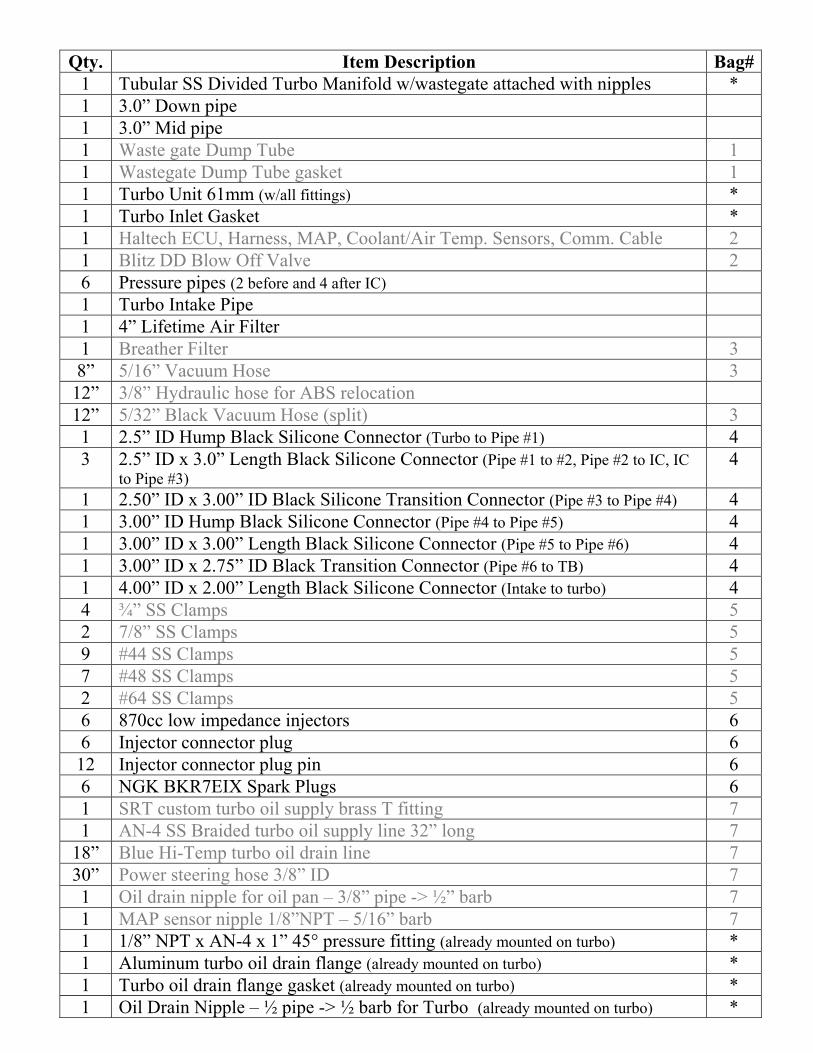
Qty. Item Description Bag#
1 Tubular SS Divided Turbo Manifold w/wastegate attached with nipples * 1 3.0” Down pipe 1 3.0” Mid pipe 1 Waste gate Dump Tube 1 1 Wastegate Dump Tube gasket 1 1 Turbo Unit 61mm (w/all fittings) * 1 Turbo Inlet Gasket * 1 Haltech ECU, Harness, MAP, Coolant/Air Temp. Sensors, Comm. Cable 2 1 Blitz DD Blow Off Valve 2 6 Pressure pipes (2 before and 4 after IC) 1 Turbo Intake Pipe 1 4” Lifetime Air Filter 1 Breather Filter 3 8” 5/16” Vacuum Hose 3
12” 3/8” Hydraulic hose for ABS relocation 12” 5/32” Black Vacuum Hose (split) 3 1 2.5” ID Hump Black Silicone Connector (Turbo to Pipe #1) 4 3 2.5” ID x 3.0” Length Black Silicone Connector (Pipe #1 to #2, Pipe #2 to IC, IC
to Pipe #3) 4
1 2.50” ID x 3.00” ID Black Silicone Transition Connector (Pipe #3 to Pipe #4) 4 1 3.00” ID Hump Black Silicone Connector (Pipe #4 to Pipe #5) 4 1 3.00” ID x 3.00” Length Black Silicone Connector (Pipe #5 to Pipe #6) 4 1 3.00” ID x 2.75” ID Black Transition Connector (Pipe #6 to TB) 4 1 4.00” ID x 2.00” Length Black Silicone Connector (Intake to turbo) 4 4 ¾” SS Clamps 5 2 7/8” SS Clamps 5 9 #44 SS Clamps 5 7 #48 SS Clamps 5 2 #64 SS Clamps 5 6 870cc low impedance injectors 6 6 Injector connector plug 6 12 Injector connector plug pin 6 6 NGK BKR7EIX Spark Plugs 6 1 SRT custom turbo oil supply brass T fitting 7 1 AN-4 SS Braided turbo oil supply line 32” long 7
18” Blue Hi-Temp turbo oil drain line 7 30” Power steering hose 3/8” ID 7 1 Oil drain nipple for oil pan – 3/8” pipe -> ½” barb 7 1 MAP sensor nipple 1/8”NPT – 5/16” barb 7 1 1/8” NPT x AN-4 x 1” 45° pressure fitting (already mounted on turbo) * 1 Aluminum turbo oil drain flange (already mounted on turbo) * 1 Turbo oil drain flange gasket (already mounted on turbo) * 1 Oil Drain Nipple – ½ pipe -> ½ barb for Turbo (already mounted on turbo) *

2 8mm x 1.25 x 25mm bolts (Grade 5 or higher, already mounted to turbo oil drain) * 2 8-32 x 3/8” SS bolts for MAF (may already be attached to MAF tube) 8 4 WG Dump tube Bolts (Grade 8 or higher) 8 4 6mm x 1.00 x 10mm bolts 8 3 6mm washers 8 1 6mm x 1.00 nut 8 2 3/8”-24 x 1.50” bolts (Grade 8 or higher for mid pipe to rear section) 8 2 3/8”-24 nuts (Grade 8 or higher for mid pipe to rear section) 8 20 Small Zip Ties (Black) 8 10 Big Zip Ties (Black) 8 1 3.0” exhaust strap (for down pipe to mid pipe) ((*** QTY 2 for GS300 ***)) 9 1 3.0” V-Band Clamp for turbo to down pipe 9 1 Walbro 255lph in tank fuel pump 10 1 New sock for fuel pump 10 1 Wire plug harness for fuel pump 10 12 #12 o-rings for injectors 10 1 Intercooler (core size: 18.0” x 12” x 3.0”, end caps: 2.0” deep, 2.5” inlet, 2.5” outlet) 1 2.5mm Head Gasket 2JZ MLS 1 ARP Head Stud Kit 2JZ 1 Manual Boost controller w/all fittings and hoses 1 Aluminum bracket for ABS System 1 Instructional CD ROM
* These items are already setup as one piece form SRT. This is done to make the installation easier for the end user.

Preparing and starting the install 1) Relieve the fuel pressure: Remove the base/bottom of the rear seat, remove the fuel pump cover
from the left side under the seat (3 plastic 10mm nuts) and then disconnect the fuel pump wiring harness. Insert the key and crank the car, if the car starts it will soon cut out, after the car turns off, crank for another 10-15 seconds, or until the engine feels like it does not want to catch any more.
2) Disconnect the negative and positive battery terminals. 3) Make sure engine is cool and exhaust manifolds are cool. Have a fire extinguisher nearby and use
extreme caution, do not smoke at or near the vehicle and make sure any source of igniting the fuel is extinguished.
4) Remove the engine cover. 5) Remove the entire factory air box inlet from the throttle body (TB); remove the MAF sensor from
the air box assembly. Install the MAF sensor on to the supplied MAF tube #5 using the factory o-ring and supplied SS bolts (make sure o-ring does not get caught and seats properly). Remove the EVAP valve from the air box assembly.
6) Remove the entire front bumper cover assembly as per manufacturer’s instructions. 7) Using pressurized air spray off dirt and debris from around the factory injectors and fuel rail area. 8) Remove the throttle body: Remove the throttle link cable, undo all wiring harnesses, remove the
lower bracket by removing the 4 nuts, then remove the two bolts and one nut on the throttle body (Picture 1).
9) Remove the upper Y-intake manifold by removing the six bolts and undoing all necessary vacuum lines. Do not reinstall the manifold or throttle body until instructed to do so.
10) Drill and tap the two holes on the Y section of the manifold as shown in Picture 19, then install the Air temperature sensor and MAP sensor nipple.
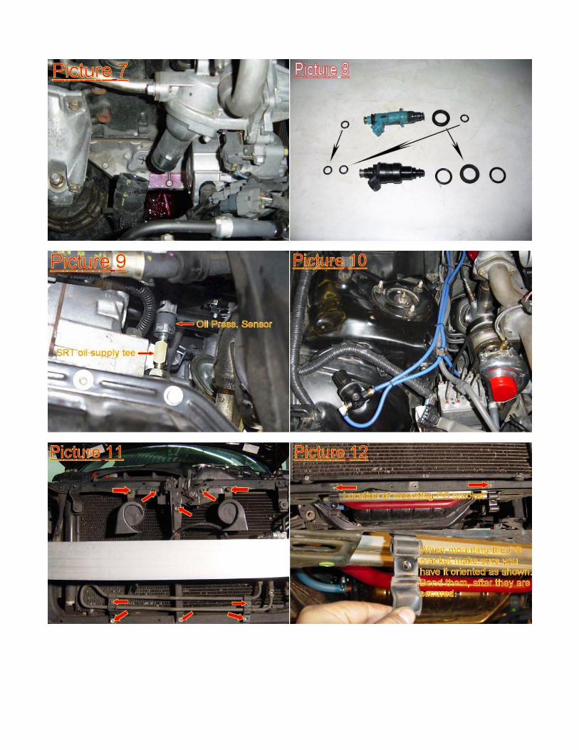
11) Remove the fuel rails and factory injectors as per manufacturer’s instructions (the fuel rail is held in place with three 12mm nuts and the supply line with a 22mm fuel damper that has 2 aluminum crush washers). Remove the large o-ring base washers from the factory injectors, clean and carefully install large washers onto the new injectors, then apply a thin coating of oil onto the top small o-rings of the new injectors and install the new injectors onto the fuel rail. Install the fuel rail with the injectors in place and follow manufacturer’s installation procedures. Cut off the factory injector connectors. Make note that each connector has a common colored wire, so connect the common colored wire to the new crimp connectors and keep in the same side of the injector. All connections MUST be crimped and soldered. See injectors picture below.
12) Remove the coils and sparkplugs. Gap the new spark plugs to 0.026”, and then install the new plugs (torque appropriately 19 ft/lbs and use anti seize compound on the threads) and coils.
13) Drain the radiator coolant from the radiator into a clean container and cover it. Also drain the entire block of coolant, there is a drain nipple on the passenger side of the block towards the back side, attach a hose to the nipple and loosen the bolt to drain the block completely. Put it aside to refill the radiator later.
14) Remove the Cam covers and Cams as per Manufacturers specifications. R&R the Head Gasket with the supplied 2.5mm Head Gasket as per manufacturers specifications. Use ARP head studs for the reinstall.
a. Place Gasket on the block. b. Carefully place the head on (having another person to help with this is priceless) c. Coat both sides of the washers with ARP moly lube and carefully put them in place using a
pick. d. Install the head studs, put a very light coating of oil on the thread section that goes in the
block (make sure you do not have too much that it drips, when I say light coating I mean light), place a generous coating of ARP moly lube in the entire thread section that the nut will go in. Use an allen key to drive the stud into the block, DO NOT OVERTIGHTEN THE STUD INTO THE BLOCK JUST HAND TIGHT USING THE ALLEN KEY UNTIL THE STUD BOTTOMS OUT. Also make sure the washers are in place.
e. Put ARP Moly Lube in the nut threads and mating surface. Use a socket and extention to drive it down by hand first. Then torque as follows:

i. First torque to 25 ft/lbs using Toyota/Lexus sequence ii. Then recheck @ 25 ft/lbs
iii. Then torque to 50 ft/lbs using Toyota/Lexus sequence iv. Then recheck @ 50 ft/lbs v. The torque to 75 ft/lbs using Toyota/Lexus sequence
vi. Then recheck @ 75 ft/lbs. vii. The MAX is 75 ft/lbs
15) Remove the brass plug underneath the number 2 intake runner in the head see Picture 21, Install the supplied coolant temperature sensor here (use some silicone on the threads).
16) Run the wiring harness from the drivers side to the factory ecu. Remove the ECU cover and connect the wiring harness in place using the attached wiring diagrams (Caution: all connections MUST be soldered). IT IS ABSOLUTELY IMPERATIVE THAT THE CORRECT DIAGRAM IS USED FOR YOUR APPLICATION, IF YOU ARE AT ALL CONFUSED PLEASE CONTACT SRT. Follow the additional O2 sensor wiring as shown in the diagrams. Replace the ECU cover.
17) Using a 3 ½” hole saw, cut a hole right underneath the factory air box as shown in the attached picture 2. Be careful not to cut any wires, etc. After the hole is cut, file sharp edges. Now install the gasket (12” long 5/32” vacuum hose that is split, as supplied) around the hole for protection and prevention of scratches and cuts as shown in picture 3.
18) Remove all four O2 sensors from the car. Three O2 sensors are in the exhaust manifold and one is in the B pipe. Remove the B pipe from the vehicle, and then remove the factory exhaust manifold as per manufacturers specs by removing the eight nuts that secure it to the cylinder head (work from the outside nuts to the inner nuts.)
19) Carefully punch a hole in the No. 2 oil pan (Sheet metal) using a 7/16” diameter punch as shown in picture 4. Once the hole is punched (make sure the hole is no bigger than 7/16” diameter), thread the hole using a 3/8 NPT pipe tap; grease the tap to catch metal shavings, regularly clean the tap and re-grease it. After the hole is tapped, clean the threads and install the brass fitting (large) for the oil drain line as shown in picture 5 (use a little bit of gray silicone on the threads.)
20) Carefully bend the lower heater core inlet towards the passenger side, and then remove the hose from the lower inlet. Cut it as shown in picture 6 and reinstall. Push the hose as far back towards the firewall as possible (you must use extreme caution in this step otherwise breakage on the heater core could result.)
21) Remove the radiator hose from the thermostat housing. Remove the two 10mm nuts that hold the housing in place. Remove the housing carefully, then rotate the housing 180° as shown in picture 7 and retighten the nuts (if the thermostat comes out with the housing make sure the thermostat is placed back with the bleeder hole pointing upwards). Reconnect the radiator hose and secure with the factory clamp.
22) Relocate ABS Assembly: a. Carefully undo all the lines going to the ABS module AFTER labeling them. b. Remove the bracket from the ABS module. c. Straighten the lines carefully one at a time. d. Reattach the lines also use the longer soft line(s) e. Use the supplied aluminum bracket to secure all the lines. f. Make sure all the lines are as close to the frame/wheel tub as possible.
23) Install the turbo manifold on the vehicle. The wastegate is already pre-mounted from SRT on the manifold to ease installation. Carefully mount the turbo manifold in place (make sure the factory exhaust manifold gaskets are in place and clean). Hold the manifold and install the eight nuts in place before tightening. Tighten the nuts by working inside out in several steps, i.e. tighten the nuts starting with the two center nuts and work yourself out.
24) Disassemble the turbo unit: a. Remove the turbine housing and install it in the Manifold b. Remove the Center cartridge and install it on the turbine housing making sure it is clocked
as shown in the picture. Make sure the oil drain is clear of the manifold. c. Install the oil supply and drain lines at this point.

d. Install the compressor housing and make sure it is clocked properly as shown. 25) Install the down pipe on the turbo with the V-band clamp (do not tighten yet). Install the wastegate
dump tube. 26) Install the mid pipe: Use the two 3/8 – 24 x 1.5” bolts and 3/8 – 24 nuts to bolt it to the factory
flange, use high temp. Use supplied gasket. Use the band clamp where the down pipe meets the mid pipe. Align everything before giving it the final tightening. Now tighten everything including the V-band clamp.
27) All the factory O2 sensors should be zip-tied away from other components but still must remain in the car.
28) Disconnect and remove the oil pressure sensor from the vehicle (located in the drivers side of the engine block in front of the oil filter), install the supplied brass T fitting where the oil pressure sensor was and then install the oil pressure sensor at the end of the fitting, install the supplied 1/8 pipe – AN4 straight fitting on the center of the fitting. Use a light coat of silicone in all connections EXCEPT the AN fitting, do not use Teflon tape. Install one end of the SS braided oil supply line to the AN fitting and route it to the turbo, secure it to the turbo, make sure the SS line is secure in place with zip ties wherever it might rub with other parts. See Picture 9.
29) Install the Y section of the intake manifold. Before you do, you must secure all vacuum hoses properly by using small plastic zip ties. Every vacuum hose end must be zip tied no matter how difficult it seems.
30) Install the throttle body in place using the two top bolts and the bottom nut/stud. Secure the lower TB bracket in place with the four nuts (run the factory wiring harness through the middle of the bracket). Reconnect all hoses and harnesses; reconnect the throttle cable back in place.
31) Install the blue high temperature oil drain line to the turbo and to the brass fitting on the oil pan, the oil drain line must come straight from the turbo and have no sharp bends or kinks. Secure with supplied 7/8” clamps.
32) Install the boost pressure regulator: The arrow on the regulator indicates the flow of air, i.e. it points from the pressure pipe to the waste gate. Connect the 5/32” vacuum hoses as shown in the diagram. Picture 10 shows the mounting of the regulator (Stage 1 shown, stage 2 similar). Secure with zip ties. To increase the boost: pull the knob up and turning it clockwise towards the + direction.
33) Install the Intercooler: Remove all the crash bar, and then remove all the bolts as shown in Picture 11. Remove the power steering cooler coil from the lines and attach the 3/8” hose supplied (this will make a loop, do not cut the supplied line yet). Carefully push the power steering lines and the A/C line towards the driver’s side and mount the intercooler (The driver side AC line can get in the way make sure to carefully bend it and move it out of the way), Use a 6mm x 1 x 10 and 6mm nut and washer to secure the intercooler top ear to the hood latch release. The lip of the frame will slide in between the intercooler and the intercooler legs. Remove the mounting tabs from the power steering cooler and mount them in the frame with the supplied 6mm x 1 x 10mm bolts, then bend them over. See Pictures 12-14.
34) Re-install the front crash bar. Make sure there is some clearance between the I/C and the crash bar. Mount the horns at the top brackets that hold the A/C condenser in place. You will need to extend the wire for the passenger side horn. Also use a piece of wire to ground the bracket of the horn to the top frame piece where the horns were originally mounted.
35) Remove the wiring harness bracket for the O2 sensors from top of the alternator and zip tie the wires as shown in picture 15.
36) Install the pressure tubes (the arrows indicate the flow of air from the turbo to the IC to the TB): a. Install a 2.50” hump connector hose to the compressor outlet and secure with a #44 clamp. b. Install the #1 tube to the connector and secure with a #44 clamp. c. Install the 2.50” x 3.00” connector to the #1 tube, then connect the #2 tube to the connector
and secure with #44 clamps. In order to install the #2 tube you need to cut the plastic underbody siding to run the tube through and you will also have to cut the washer fluid overflow tube and shorten it.
d. Install a 2.50” x 3.00” connector to the #2 tube then connect it to the intercooler, and secure with #44 clamps.
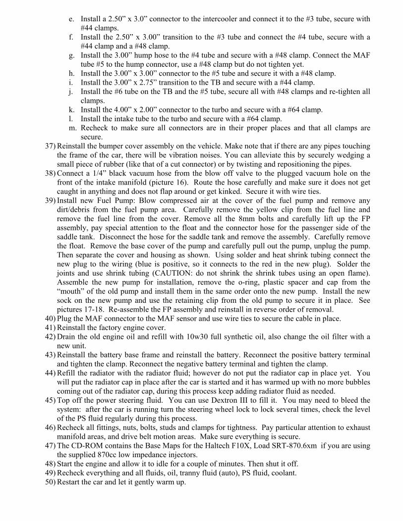
e. Install a 2.50” x 3.0” connector to the intercooler and connect it to the #3 tube, secure with #44 clamps.
f. Install the 2.50” x 3.00” transition to the #3 tube and connect the #4 tube, secure with a #44 clamp and a #48 clamp.
g. Install the 3.00” hump hose to the #4 tube and secure with a #48 clamp. Connect the MAF tube #5 to the hump connector, use a #48 clamp but do not tighten yet.
h. Install the 3.00” x 3.00” connector to the #5 tube and secure it with a #48 clamp. i. Install the 3.00” x 2.75” transition to the TB and secure with a #44 clamp. j. Install the #6 tube on the TB and the #5 tube, secure all with #48 clamps and re-tighten all
clamps. k. Install the 4.00” x 2.00” connector to the turbo and secure with a #64 clamp. l. Install the intake tube to the turbo and secure with a #64 clamp. m. Recheck to make sure all connectors are in their proper places and that all clamps are
secure. 37) Reinstall the bumper cover assembly on the vehicle. Make note that if there are any pipes touching
the frame of the car, there will be vibration noises. You can alleviate this by securely wedging a small piece of rubber (like that of a cut connector) or by twisting and repositioning the pipes.
38) Connect a 1/4” black vacuum hose from the blow off valve to the plugged vacuum hole on the front of the intake manifold (picture 16). Route the hose carefully and make sure it does not get caught in anything and does not flap around or get kinked. Secure it with wire ties.
39) Install new Fuel Pump: Blow compressed air at the cover of the fuel pump and remove any dirt/debris from the fuel pump area. Carefully remove the yellow clip from the fuel line and remove the fuel line from the cover. Remove all the 8mm bolts and carefully lift up the FP assembly, pay special attention to the float and the connector hose for the passenger side of the saddle tank. Disconnect the hose for the saddle tank and remove the assembly. Carefully remove the float. Remove the base cover of the pump and carefully pull out the pump, unplug the pump. Then separate the cover and housing as shown. Using solder and heat shrink tubing connect the new plug to the wiring (blue is positive, so it connects to the red in the new plug). Solder the joints and use shrink tubing (CAUTION: do not shrink the shrink tubes using an open flame). Assemble the new pump for installation, remove the o-ring, plastic spacer and cap from the “mouth” of the old pump and install them in the same order onto the new pump. Install the new sock on the new pump and use the retaining clip from the old pump to secure it in place. See pictures 17-18. Re-assemble the FP assembly and reinstall in reverse order of removal.
40) Plug the MAF connector to the MAF sensor and use wire ties to secure the cable in place. 41) Reinstall the factory engine cover. 42) Drain the old engine oil and refill with 10w30 full synthetic oil, also change the oil filter with a
new unit. 43) Reinstall the battery base frame and reinstall the battery. Reconnect the positive battery terminal
and tighten the clamp. Reconnect the negative battery terminal and tighten the clamp. 44) Refill the radiator with the radiator fluid; however do not put the radiator cap in place yet. You
will put the radiator cap in place after the car is started and it has warmed up with no more bubbles coming out of the radiator cap, during this process keep adding radiator fluid as needed.
45) Top off the power steering fluid. You can use Dextron III to fill it. You may need to bleed the system: after the car is running turn the steering wheel lock to lock several times, check the level of the PS fluid regularly during this process.
46) Recheck all fittings, nuts, bolts, studs and clamps for tightness. Pay particular attention to exhaust manifold areas, and drive belt motion areas. Make sure everything is secure.
47) The CD-ROM contains the Base Maps for the Haltech F10X, Load SRT-870.6xm if you are using the supplied 870cc low impedance injectors.
48) Start the engine and allow it to idle for a couple of minutes. Then shut it off. 49) Recheck everything and all fluids, oil, tranny fluid (auto), PS fluid, coolant. 50) Restart the car and let it gently warm up.

51) The Base Maps are just to start the vehicle and move it short distance to get to a dyno tuning facility, ensure the car is properly tuned before boosting and driving. This should be done on a dyno and using a Wide Band Air Fuel Ratio sensor.
52) Setting the boost (two person job, make sure you do not break any local laws, ALSO MAKE SURE THE CAR IS FULLY TUNED BEFORE DOING SO):
a. Make sure the boost regulator is set all the way to the - sign until it stops (minimum boost). b. Have a boost gauge connected to the intake manifold. c. After the car has warmed up completely, take it for a test drive, while having the car on
third gear, get it to about 3500 RPM, then slowly depress the accelerator pedal until you are fully depressed on the pedal at about 4500 RPM, check the boost gauge constantly and see where it stabilizes.
d. To increase boost turn the boost regulator counter clockwise about ¼ turn towards the + (positive) then test drive again, repeat until you have the boost at 14.0 PSI MAX.
e. Increasing the boost beyond the 14.0 PSI limit WILL result in engine damage and VOID all warranties.
53) Then take a test drive, Check for any and all leaks regularly, also check your oil level at every gas fillup.
54) Incomplete or partial assembly or substituting components that are not SRT approved of the kit and driving around will cause damage to the vehicle and void all warranties.
SRT does not assume any liabilities or damages caused directly or indirectly by the use or misuse of the Turbo Charger system. The system is warranted for 6 months from manufacturers defect and craftsmanship from date of purchase. This product is not intended for use in public highways, it is endorsed by SRT to be used for racing only on non-public highways and off road. It is the consumers responsibility to check local laws regarding emissions regulations and vehicle safety equipment standards.