Embed Size (px)
Citation preview

Zone 1 & 21 Universal Access Point Enclosure System I Copyright Extronics Ltd 2010 1
Zone1 & 21 Universal
Access Point Enclosure
System

Zone 1 & 21 Universal Access Point Enclosure System I Copyright Extronics Ltd 2010 2
iWAP101 & iWAP103 Universal Access Point Enclosure System
iWAP101 & iWAP103 Universal Access Point Enclosure System
Multi wireless vendor support with solutions for most
leading products
Designed to protect standard wireless products from harsh
industrial environments
Can be re-certified in future to incorporate the latest
generation of wireless equipment as technology evolves
Range of high quality omni direction antennas for best
possible wireless performance
iWAP101 variant designed for bespoke applications where
special hardware is required
Introduction
Zone 1 & 21 Universal Access Point Enclosure System I Copyright Extronics Ltd 2010 3
General SpecificationsGeneral Specifications
ATEX Zone 1 and Zone 21 certified
II 2 G EEx d IIC T5 Ta 55°C Max,
T6/Ta 40°C
Ex tD A21 IP66 T100°C@Ta55°C,
T85°C@Ta40°C
IP66 rugged enclosure
Marine grade alloy for high
resistance to corrosion
-20°C to +55°C ambient
temperature range
Features & Benefits
Zone 1 & 21 Universal Access Point Enclosure System I Copyright Extronics Ltd 2010 4
Designed For Your Access Point
Designed For Your Access Point
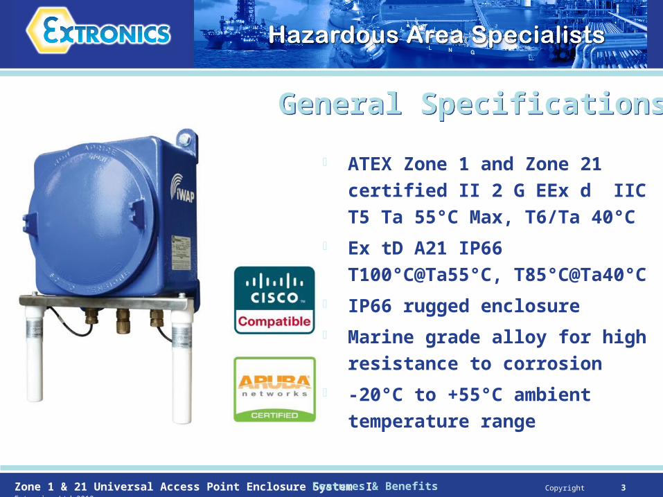
Suitable for basically any vendors Access Point or wireless device providing it meets certain volumetric, cross sectional and power dissipation criteria and has no batteries or fans in the device
Thermally tested to determine maximum ambient operating temperature
Internal fittings and cabling included
Features & Benefits
Zone 1 & 21 Universal Access Point Enclosure System I Copyright Extronics Ltd 2010 5
Easy InstallationEasy Installation
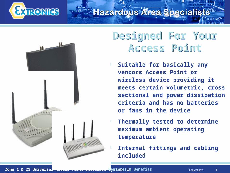
Standard PCB with all connections in same location whatever the internally fitted wireless device
Screw terminals for Ethernet so no need to fit an RJ45 connector to the CAT5 cable when fitted in the gland
All connections on top near the enclosure lid
Optional Ex e terminal enclosure so that Ex e installation principles apply
Features & Benefits

Zone 1 & 21 Universal Access Point Enclosure System I Copyright Extronics Ltd 2010 6
Two or four internal surge
arrestors to protect Access
Point from damage caused
by lightning strikes on the
plant
Optional Features
Optional Features – Surge Arrestors
Optional Features – Surge Arrestors

Zone 1 & 21 Universal Access Point Enclosure System I Copyright Extronics Ltd 2010 7
Improve the lower ambient
operating temperature of your
wireless device down to -20°C
from typical 0°C for indoor
Access Points
Protect Access Points from
condensation
Improve reliability by ensuring a
relatively constant operating
temperature for the Access Point
Optional Features – Heaters
Optional Features – Heaters
Optional Features

Zone 1 & 21 Universal Access Point Enclosure System I Copyright Extronics Ltd 2010 8
Connect up to four external
Ethernet devices
Two of the four ports are
802.3af compatible POE ports
to power external POE devices
such as IP Cameras
Optional Features – POE Switch
Optional Features – POE Switch
Optional Features
Zone 1 & 21 Universal Access Point Enclosure System I Copyright Extronics Ltd 2010 9
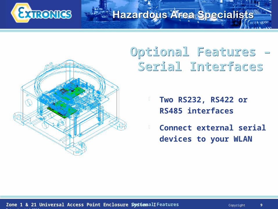
Two RS232, RS422 or RS485
interfaces
Connect external serial
devices to your WLAN
Optional Features – Serial Interfaces
Optional Features – Serial Interfaces
Optional Features
Zone 1 & 21 Universal Access Point Enclosure System I Copyright Extronics Ltd 2010 10
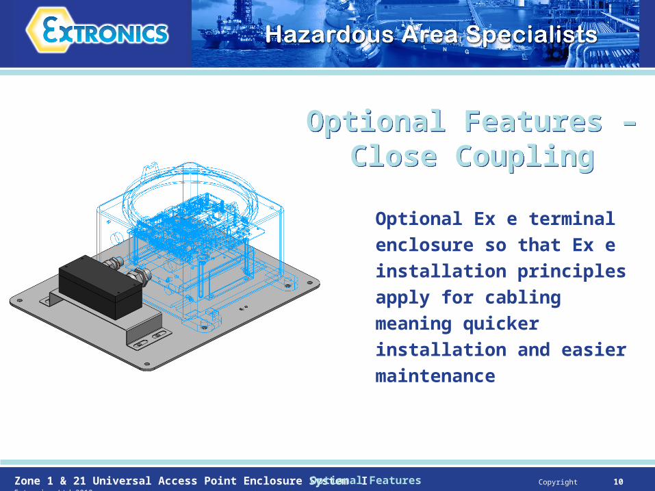
Optional Ex e terminal
enclosure so that Ex e
installation principles apply
for cabling meaning quicker
installation and easier
maintenance
Optional Features – Close Coupling
Optional Features – Close Coupling
Optional Features

Zone 1 & 21 Universal Access Point Enclosure System I Copyright Extronics Ltd 2010 11
Live disconnect of power supply
and or Ethernet for POE iWAP’s
in the hazardous area possible
using Ex de certified connectors
Optional Features – Live Disconnect
Optional Features – Live Disconnect
Optional Features

Zone 1 & 21 Universal Access Point Enclosure System I Copyright Extronics Ltd 2010 12
Increased safety Ex e antennas
for connection to the Access
Point in the enclosure
2.4GHz 5 dBi and 5 GHz 8 dBi
band A, B and C versions
Locally mounted to enclosure
using optional iANTMB02 bracket
Antennas – Locally Mounted
Antennas – Locally Mounted
Antennas

Zone 1 & 21 Universal Access Point Enclosure System I Copyright Extronics Ltd 2010 13
Increased safety Ex e antennas for connection to the Access Point in the enclosure
2.4GHz 5 dBi and 5 GHz 8 dBi band A, B and C versions
5 metres coax cable means antenna can be mounted on a wall or other structure using aluminium bracket included or 316L st iANTMB03 bracket to allow antenna to be mounted in optimal location
Antennas – Locally Mounted
Antennas – Locally Mounted
Antennas

Zone 1 & 21 Universal Access Point Enclosure System I Copyright Extronics Ltd 2010 14
Increased safety Ex e antennas for connection to the Access Point mounted remotely outside of the hazardous area - No iWAP103 enclosure system required
2.4GHz 5 dBi and 5 GHz 8 dBi band A, B and C versions
10, 15, 20, 25 or 30 metres coax cable with connector to suit your Access Point – special lengths on request
Surface mounted using the iANTMB01 bracket
Access Point
Safe Area
Hazardous AreaRemote antenna
Antennas – Locally Mounted
Antennas – Locally Mounted
Antennas