Embed Size (px)
Citation preview
Presented by: Dr. Ben Chapman, Director – Line Pipe Products & Services
30th April 2019
Zap-Lok – A Mechanical Interference Connectionto Overcome Today’s Offshore Installation Challenges

2
Contents
1. Enabling Concept1.1 Zap-Lok Mechanical Interferece Connection and Interal Plastic Coating (IPC)1.2 Zap-Lok / Internal Plastic Coating (IPC) Design1.3 Utilization of Vessels of Opportunity1.4 Modular Pipelay System (MPS)1.5 Tie-back Cost Summary – DP2 S-Lay
2. Zap-Lok Mechanical Interference Connection2.1 Operating Envelope2.2 End Preparation2.3 End Preparation Quality Control2.4 Installation Equipment2.5 Jointing2.6 Installation Quality Control2.7 Certificates of Conformity
3. Internal Plastic Coating (IPC)3.1 Hydraulic Efficiency & Corrosion Coatings3.2 Manufacture3.3 Reductions in CAPEX and OPEX3.4 Line Pipe Coating Performance
4. Conclusion

3
1. Enabling Concept
1.1 Zap-Lok Mechanical Interference Connection and Internal Plastic Coating (IPC)
Diameter. (NPS): 2 to 16-inch (50-400mm)
Wall thickness: Up to 1.000” (25.4mm)
Material: Grade B to X70; SMLS, HFI or ERW
Service: Sweet and sour crude, gas, condensate, water, steam
Pressure: As per line pipe material specification
Corrosion Barrier: Epoxy / Phenolic – up to 2% H2S, CO2, Acids, SRBs
1. Enabling Concept
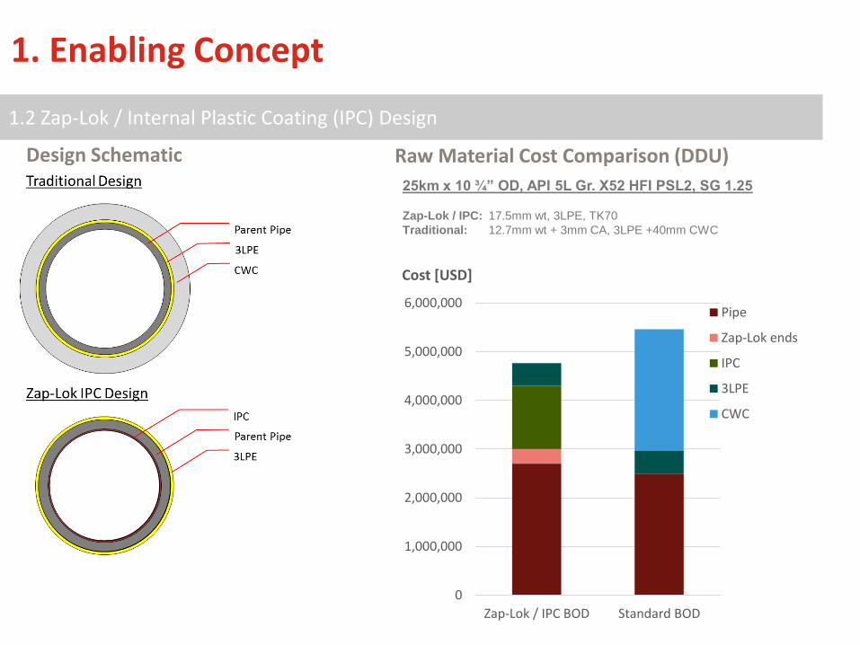
1.2 Zap-Lok / Internal Plastic Coating (IPC) Design
Zap
Raw Material Cost Comparison (DDU)Design Schematic
0
1,000,000
2,000,000
3,000,000
4,000,000
5,000,000
6,000,000
Zap-Lok / IPC BOD Standard BOD
Cost [USD]
Pipe
Zap-Lok ends
IPC
3LPE
CWC
25km x 10 ¾” OD, API 5L Gr. X52 HFI PSL2, SG 1.25
Zap-Lok / IPC: 17.5mm wt, 3LPE, TK70
Traditional: 12.7mm wt + 3mm CA, 3LPE +40mm CWC

1. Enabling Concept
1.3 Utilization of Vessels of Opportunity
Zap-Lok connectors enable the end user to consider smaller vessels of opportunity as the amount of offshore work
is reduced, i.e. only one connection station no field jointing stations are required. Considering a standard S-Lay
construction method, the mobilization / demobilization costs and day rates are dramatically reduced.
Zap

1. Enabling Concept
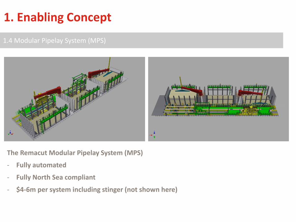
1.4 Modular Pipelay System (MPS)
Zap
Integral A-frame & Modular Stinger
Tensioner
Zap-Lok Press
Pipe feed table
Control Cabin, Workshop Container, Hydraulic Power Units
Pipe Lifting System
Pipe Storage Racks
Pipe Conveyor
Pipe OD (in)Pipe Stored on Back Deck (km)
800 m2 1200 m2 1600 m2
6 26 30 40
8 20 24 32
10 15 21 27
12 11 17 23
14 9 14 20
16 7 11 15
1. Enabling Concept
1.4 Modular Pipelay System (MPS)
Zap
ZapThe Remacut Modular Pipelay System (MPS)
- Fully automated
- Fully North Sea compliant
- $4-6m per system including stinger (not shown here)
1.4 Modular Pipelay System (MPS)
1. Enabling Concept
1. Enabling Concept
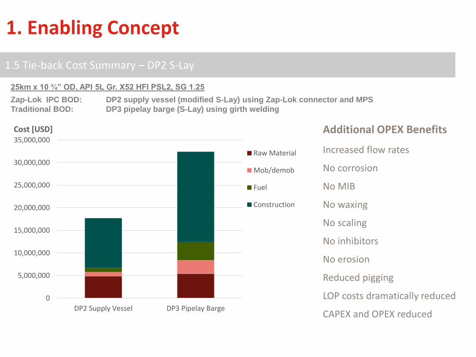
1.5 Tie-back Cost Summary – DP2 S-Lay
ZapZap
0
5,000,000
10,000,000
15,000,000
20,000,000
25,000,000
30,000,000
35,000,000
DP2 Supply Vessel DP3 Pipelay Barge
Cost [USD]
Raw Material
Mob/demob
Fuel
Construction
Zap-Lok IPC BOD: DP2 supply vessel (modified S-Lay) using Zap-Lok connector and MPS
Traditional BOD: DP3 pipelay barge (S-Lay) using girth welding
25km x 10 ¾” OD, API 5L Gr. X52 HFI PSL2, SG 1.25
Additional OPEX Benefits
Increased flow rates
No corrosion
No MIB
No waxing
No scaling
No inhibitors
No erosion
Reduced pigging
LOP costs dramatically reduced
CAPEX and OPEX reduced

Test Average Result Compliance
Axial Tension 70% UTS ASME B31.4 / B31.8, ISO 21329 (app. Level 4)
Axial Compression > 95% UTS ASME B31.4 / B31.8, ISO 21329 (app. Level 4)
Internal Pressure > 95% UTS ASME B31.4 / B31.8, ISO 21329 (app. Level 4)
Bending > 95% UTS ASME B31.4 / B31.8, ISO 21329 (app. Level 4)
Fatigue – in air DnV D Class weld curve BS 7608 F2 / DNV C1, ISO 21329 (app. Level 4)
Fatigue –in water DnV C2 Class weld curve BS 7608 F2 / DNV C1, ISO 21329 (app. Level 4)
Stress Corrosion Cracking No reduction in strength NACE MR0175 / NACE TM0177 – Method A
Crevice Corrosion No reduction in strength1 month exposure at 130°F and 500psi in brine with 1,000ppmacetic acid, 30% CO2, 70%N2
Electrical Resistivity ±1μΩ / connection N.B. 10A, 25mV FSD
2. Zap-Lok Mechanical Interference Connection
2.1 Operating Envelope

Stresses during mandrel insertion Stresses following pin insertion.
2. Zap-Lok Mechanical Interference Connection
2.1 Operating Envelope
Make-Up Loads - Static
12-inch, 0.500” wt, Grade X65
Pin wrinkling
Separation ofpin from bell
Hoop stress and bendingmoment on pin end
Bending to 30m radius.
Bending to 140m radius Bending to 67m radius
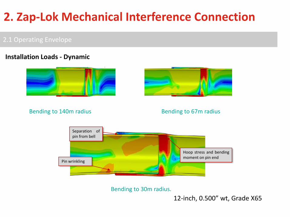
2. Zap-Lok Mechanical Interference Connection
2.1 Operating Envelope
Installation Loads - Dynamic
12-inch, 0.500” wt, Grade X65

2. Zap-Lok Mechanical Interference Connection
2.1 Operating Envelope
Service Loads - Static
Pressure to Failure Tension to Failure Bending and Tension
12-inch, 0.500” wt, Grade X65

2. Zap-Lok Mechanical Interference Connection
2.1 Operating Envelope
Service Loads - Dynamic
DNV-RP-C203 and Zap-Lok S-N Curves in Seawater with CP vs. Weld Curves

©2016 Tuboscope | NOV Wellbore Technology - Proprietary and confidential. Zap-Lok Technology - 06/09/16 | 15
• Mobile plant reduces handling costs – 3 x 40ft ISO containers• Safe production of ends with Zap-Lok experts and local labour• High production rate of 2,000-3,000m/12hr shift• QC checks conducted at plant ensuring consistency of shipped product.• Repeatability of production method permits CAR insurance on connection.
Powder & Liquid Coatings2.2 End Preparation
1. Zap-Lok Mechanical Interference Connection

©2016 Tuboscope | NOV Wellbore Technology - Proprietary and confidential. Zap-Lok Technology - 06/09/16 | 16
Powder & Liquid Coatings2.2 End Preparation
2. Zap-Lok Mechanical Interference Connection

©2016 Tuboscope | NOV Wellbore Technology - Proprietary and confidential. Zap-Lok Technology - 06/09/16 | 17
➢ Tuboscope inspectors complete 100% visual and dimensional inspections using calibrated equipment during end preparation.
➢ 100% MPI and 10% UT are generally conducted for offshore products.
➢ 3 x control burst tests are completed on joints taken from each mill heat.
Powder & Liquid Coatings2.3 End Preparation Quality Control
2. Zap-Lok Mechanical Interference Connection
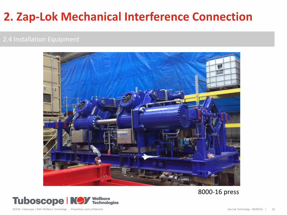
©2016 Tuboscope | NOV Wellbore Technology - Proprietary and confidential. Zap-Lok Technology - 06/09/16 | 18
Powder & Liquid Coatings2.4 Installation Equipment
2. Zap-Lok Mechanical Interference Connection
8000-16 press

©2016 Tuboscope | NOV Wellbore Technology - Proprietary and confidential. Zap-Lok Technology - 06/09/16 | 19
Powder & Liquid Coatings2.5 Jointing
2. Zap-Lok Mechanical Interference Connection
16-inch, 0.843” wt, Grade X65
©2016 Tuboscope | NOV Wellbore Technology - Proprietary and confidential. Zap-Lok Technology - 06/09/16 | 20
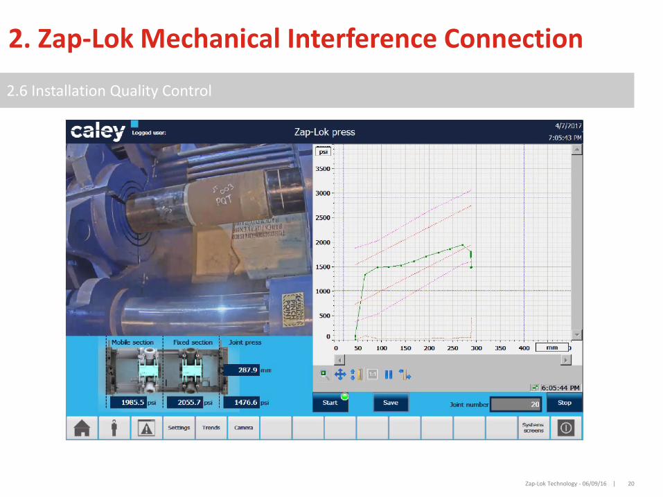
Powder & Liquid Coatings2.6 Installation Quality Control
2. Zap-Lok Mechanical Interference Connection

Zap-Lok Technology - 06/09/16 | 21
Powder & Liquid Coatings2.7 Certificates of Conformity
2. Zap-Lok Mechanical Interference Connection
2
• BV witnessed certificate of conformity demonstrating onshore compliance with ASME B31.4
• Lloyd’s Register Energy conformity certification for offshore compliance as per DNV-OS-F101

22
3. Internal Plastic Coating (IPC)
3.1 Flow efficiency & Corrosion Coatings
Corrosion Coatings
ProvideFlow
Efficiency
Starting Point:
Internal Plastic Coatings
Flow efficiency coatings
Smoothness
Consistent surface
Corrosion coatings
Chemistry
Thickness
- Limited design life- Thickness: 40-125μm- Air-cured- Sometimes holiday checked- 4-5 yr life in harsh conditions
- 20-50 year design life- Thickness: 150-500μm- Heat-cured- Rigourously holiday checked
But not vice versa
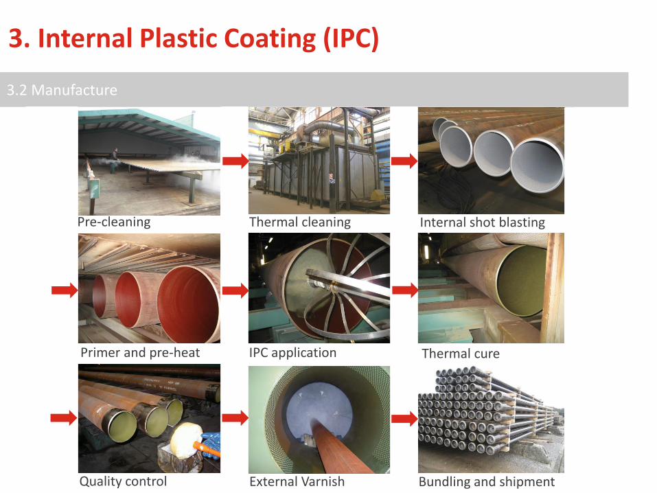
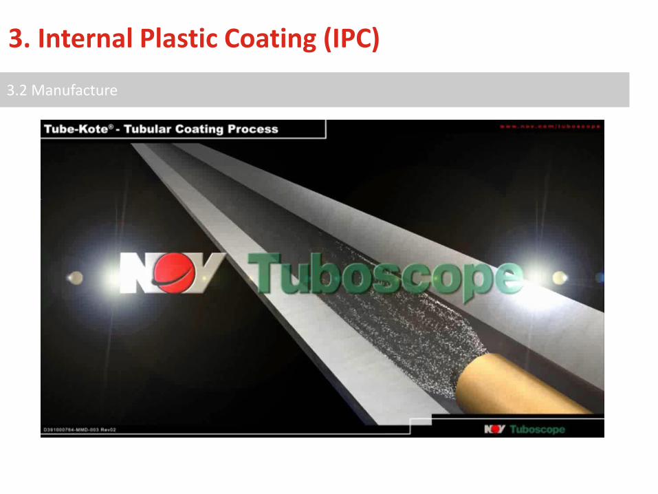
3. Internal Plastic Coating (IPC)
3.2 Manufacture
23
Pre-cleaning Thermal cleaning Internal shot blasting
Primer and pre-heat IPC application Thermal cure
Quality control External Varnish Bundling and shipment
3. Internal Plastic Coating (IPC)
3.2 Manufacture
25
3. Internal Plastic Coating (IPC)
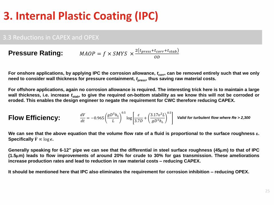
3.3 Reductions in CAPEX and OPEX
Pressure Rating: 𝑀𝐴𝑂𝑃 = 𝑓 × 𝑆𝑀𝑌𝑆 ×2 𝑡𝑝𝑟𝑒𝑠𝑠+𝑡𝑐𝑜𝑟𝑟+𝑡𝑠𝑡𝑎𝑏
𝑂𝐷
For onshore applications, by applying IPC the corrosion allowance, tcorr, can be removed entirely such that we only
need to consider wall thickness for pressure containment, tpress, thus saving raw material costs.
For offshore applications, again no corrosion allowance is required. The interesting trick here is to maintain a large
wall thickness, i.e. increase tstab, to give the required on-bottom stability as we know this will not be corroded oreroded. This enables the design engineer to negate the requirement for CWC therefore reducing CAPEX.
Flow Efficiency:𝑑𝑉
𝑑𝑡= −0.965
𝑔𝐷5ℎ𝐿𝐿
0.5
log𝜀
3.7𝐷+
3.17𝜐2𝐿
𝑔𝐷3ℎ𝐿
0.5
We can see that the above equation that the volume flow rate of a fluid is proportional to the surface roughness e.
Specifically ሶ𝑽 ∝ log 𝝐.
Generally speaking for 6-12” pipe we can see that the differential in steel surface roughness (45mm) to that of IPC
(1.5mm) leads to flow improvements of around 20% for crude to 30% for gas transmission. These ameliorations
increase production rates and lead to reduction in raw material costs – reducing CAPEX.
It should be mentioned here that IPC also eliminates the requirement for corrosion inhibition – reducing OPEX.
Valid for turbulent flow where Re > 2,300
26
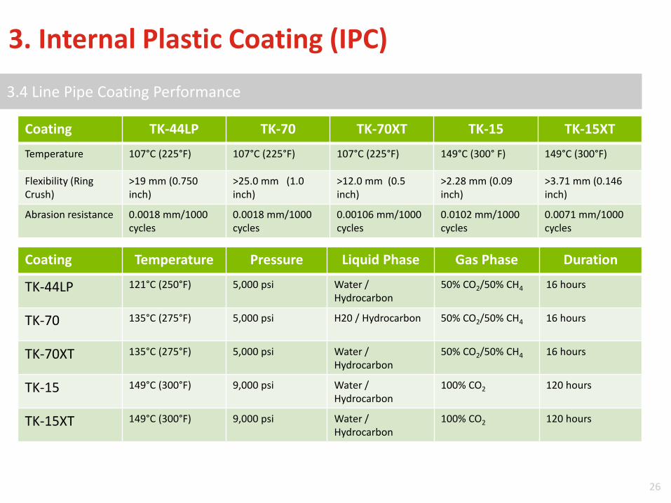
Powder & Liquid Coatings3.4 Line Pipe Coating Performance
Coating TK-44LP TK-70 TK-70XT TK-15 TK-15XT
Temperature 107°C (225°F) 107°C (225°F) 107°C (225°F) 149°C (300° F) 149°C (300°F)
Flexibility (Ring Crush)
>19 mm (0.750 inch)
>25.0 mm (1.0 inch)
>12.0 mm (0.5 inch)
>2.28 mm (0.09 inch)
>3.71 mm (0.146 inch)
Abrasion resistance 0.0018 mm/1000 cycles
0.0018 mm/1000 cycles
0.00106 mm/1000 cycles
0.0102 mm/1000 cycles
0.0071 mm/1000 cycles
3. Internal Plastic Coating (IPC)
Coating Temperature Pressure Liquid Phase Gas Phase Duration
TK-44LP 121°C (250°F) 5,000 psi Water / Hydrocarbon
50% CO2/50% CH4 16 hours
TK-70 135°C (275°F) 5,000 psi H20 / Hydrocarbon 50% CO2/50% CH4 16 hours
TK-70XT 135°C (275°F) 5,000 psi Water / Hydrocarbon
50% CO2/50% CH4 16 hours
TK-15 149°C (300°F) 9,000 psi Water / Hydrocarbon
100% CO2 120 hours
TK-15XT 149°C (300°F) 9,000 psi Water / Hydrocarbon
100% CO2 120 hours
27
Conclusion
Technical• Zap-Lok connectors, having gained full industry acceptance, qualification and significant track
record enable end-users to dramatically reduce installation costs of in field gathering systems.• IPC is a fully qualified and proven system that gives lifetime corrosion integrity to in-field
flowlines enabling the modified design techniques to be used to provide a more cost effectivepipeline basis of design.
• The combined Zap-Lok technology is best suited to shallow water installations (up to 200m),encompassing relatively sour service where it is an ideal option for most applications.
Commercial• Zap-Lok combined with Internal Coatings cab provide can significant savings on raw material
costs, for offshore line pipe.• These cost savings are amplified to give Capex installation cost savings that can be achieved
using vessels of opportunity and modular pipelay (handling) systems for installation..• Opex costs are dramatically reduced through improvements in hydraulic efficiency, elimination
of inhibitors, and reduction in corrosion, erosion and therefore maintenance.

©2014 NOV | Proprietary and confidential. Presentation Name - 00/00/00 | 28
Questions?
Contacts:
Mr. Edward Currey, Offshore Sales [email protected]@nov.com
Mr. Ekkehard Ebert, Business Development [email protected]
Dr. Ben Chapman, Line Pipe Products & Services [email protected]