Embed Size (px)
Citation preview
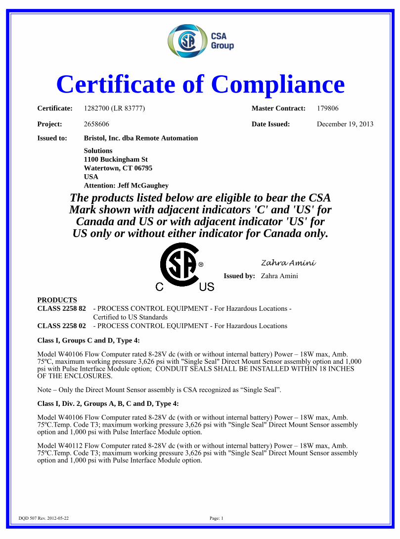
Certificate of ComplianceCertificate: 1282700 (LR 83777) Master Contract: 179806
Project: 2658606 Date Issued: December 19, 2013
DQD 507 Rev. 2012-05-22 Page: 1
Issued to: Bristol, Inc. dba Remote Automation
Solutions1100 Buckingham StWatertown, CT 06795USAAttention: Jeff McGaughey
The products listed below are eligible to bear the CSAMark shown with adjacent indicators 'C' and 'US' for
Canada and US or with adjacent indicator 'US' forUS only or without either indicator for Canada only.
Zahra Amini
Issued by: Zahra Amini
PRODUCTSCLASS 2258 82 - PROCESS CONTROL EQUIPMENT - For Hazardous Locations -
Certified to US StandardsCLASS 2258 02 - PROCESS CONTROL EQUIPMENT - For Hazardous Locations
Class I, Groups C and D, Type 4:
Model W40106 Flow Computer rated 8-28V dc (with or without internal battery) Power – 18W max, Amb.75ºC, maximum working pressure 3,626 psi with "Single Seal" Direct Mount Sensor assembly option and 1,000psi with Pulse Interface Module option; CONDUIT SEALS SHALL BE INSTALLED WITHIN 18 INCHESOF THE ENCLOSURES.
Note – Only the Direct Mount Sensor assembly is CSA recognized as “Single Seal”.
Class I, Div. 2, Groups A, B, C and D, Type 4:
Model W40106 Flow Computer rated 8-28V dc (with or without internal battery) Power – 18W max, Amb.75ºC.Temp. Code T3; maximum working pressure 3,626 psi with "Single Seal" Direct Mount Sensor assemblyoption and 1,000 psi with Pulse Interface Module option.
Model W40112 Flow Computer rated 8-28V dc (with or without internal battery) Power – 18W max, Amb.75ºC.Temp. Code T3; maximum working pressure 3,626 psi with "Single Seal" Direct Mount Sensor assemblyoption and 1,000 psi with Pulse Interface Module option.
Certificate: 1282700 (LR 83777) Master Contract: 179806
Project: 2658606 Date Issued: December 19, 2013
DQD 507 Rev. 2012-05-22 Page: 2
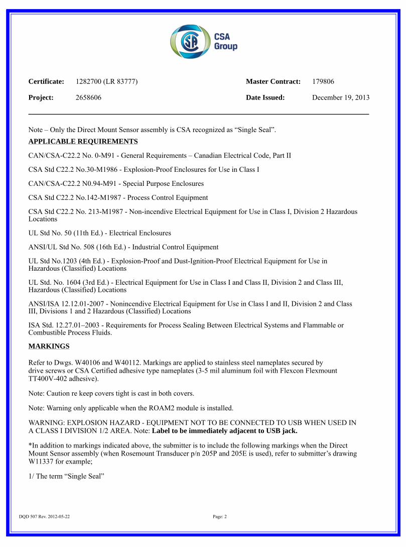
Note – Only the Direct Mount Sensor assembly is CSA recognized as “Single Seal”.APPLICABLE REQUIREMENTS
CAN/CSA-C22.2 No. 0-M91 - General Requirements – Canadian Electrical Code, Part II
CSA Std C22.2 No.30-M1986 - Explosion-Proof Enclosures for Use in Class I
CAN/CSA-C22.2 N0.94-M91 - Special Purpose Enclosures
CSA Std C22.2 No.142-M1987 - Process Control Equipment
CSA Std C22.2 No. 213-M1987 - Non-incendive Electrical Equipment for Use in Class I, Division 2 HazardousLocations
UL Std No. 50 (11th Ed.) - Electrical Enclosures
ANSI/UL Std No. 508 (16th Ed.) - Industrial Control Equipment
UL Std No.1203 (4th Ed.) - Explosion-Proof and Dust-Ignition-Proof Electrical Equipment for Use inHazardous (Classified) Locations
UL Std. No. 1604 (3rd Ed.) - Electrical Equipment for Use in Class I and Class II, Division 2 and Class III,Hazardous (Classified) Locations
ANSI/ISA 12.12.01-2007 - Nonincendive Electrical Equipment for Use in Class I and II, Division 2 and ClassIII, Divisions 1 and 2 Hazardous (Classified) Locations
ISA Std. 12.27.01–2003 - Requirements for Process Sealing Between Electrical Systems and Flammable orCombustible Process Fluids.
MARKINGS
Refer to Dwgs. W40106 and W40112. Markings are applied to stainless steel nameplates secured bydrive screws or CSA Certified adhesive type nameplates (3-5 mil aluminum foil with Flexcon FlexmountTT400V-402 adhesive).
Note: Caution re keep covers tight is cast in both covers.
Note: Warning only applicable when the ROAM2 module is installed.
WARNING: EXPLOSION HAZARD - EQUIPMENT NOT TO BE CONNECTED TO USB WHEN USED INA CLASS I DIVISION 1/2 AREA. Note: Label to be immediately adjacent to USB jack.
*In addition to markings indicated above, the submitter is to include the following markings when the DirectMount Sensor assembly (when Rosemount Transducer p/n 205P and 205E is used), refer to submitter’s drawingW11337 for example;
1/ The term “Single Seal”
Certificate: 1282700 (LR 83777) Master Contract: 179806
Project: 2658606 Date Issued: December 19, 2013
DQD 507 Rev. 2012-05-22 Page: 3
2/ The process fluid temperature range
Note - Jurisdictions in Canada may require these markings to also be provided in French language. It is theresponsibility of the manufacturer to provide bilingual marking, where applicable, in accordance with therequirements of the Provincial Regulatory Authorities. It is the responsibility of the manufacturer to determinethis requirement and have bilingual wording added to the "Markings".
Supplement to Certificate of Compliance
Certificate: 1282700 Master Contract: 179806
DQD 507 Rev. 2012-05-22 Page: 1
The products listed, including the latest revision described below, areeligible to be marked in accordance with the referenced Certificate.
Product Certification History
Project Date Description
2658606 Dec 19, 2013 This project was updated to Cover ATEX requirement (adding holes to thesensor housing as a place to clip for sensor change), Modify and change someof drawings, Apply housing flange shape change onmodels W40106 andW40112
2225713 Oct 2, 2009 Update to Report 1282700 to include the use of another manufacturing facilityto make the aluminum die cast electronics housing.
2153434 May 19, 2009 Update of report to cover evaluation of Single Seal2129567 Mar 3, 2009 Update Report 1282700 to include addition of Remote Operator Access Module
(ROAM2) to the FloBoss 103 and 104 Flow Manager.2099135 Jan 8, 2009 Update to Report 1282700 to include the addition of Remote Operator Access
Module (ROAM) to the FloBoss 103 and 104 Flow Manager.1934252 Aug 28, 2007 Update to cover addition of investment cast SST blanking cover for Flow
Computer1800071 Jul 7, 2006 Update to cover alternative external LOI connector for Model W401121648330 Mar 8, 2005 Addition of MicroMotion MVD Interface Option1593904 Sep 13, 2004 Addition of 2.4 GHz Radio1542934 Jun 7, 2004 Addition of Pulse Interface Module option and Smart Termination Board1510345 Dec 22, 2003 Revised construction to include radio modem assembly and alternate 5W solar
panel.
History
1422243 April 3, 2003 Revised construction including alternate die cast covers solar mast and coupling and adhesivenameplates.
1352978 Aug. 26, 2002 Addition of Div. 2 to Model 40106 and addition of Model 40112.
1282700 June 12, 2002 Original Certification.
Descriptive Report and Test Results
MASTER CONTRACT: 179806 REPORT: 1282700
PROJECT: 2658606 Edition 1: June 12, 2002; Project 1282700 - Toronto
Issued by L.J.Ballantyne Edition 11: March 2, 2009; Project 2129567 – Edmonton
Issued by David Wood; Reviewed by Andrew Redeker C.E.T.
Edition 12: May 19, 2009; Project 2153434 – Toronto Issued by Joe da Silva, C.E.T.
Edition 13: October 2, 2009; Project 2225713 – Cleveland Issued by Richard Dibler Jr; Reviewed by Andrew Sargent Report pages reissued
Edition 14: December 19, 2013; Project 2658606 – Toronto Issued by Zahra Amini, Reviewed by Glenn Black Report pages reissued Contents: Certificate of Compliance - Pages 1 to 3
Supplement to Certificate of Compliance – Page 1 Description and Tests - Pages 1 to 19 Descriptive Documents – Engineering files only
PRODUCTS CLASS 2258 02 - PROCESS CONTROL EQUIPMENT - For Hazardous Locations CLASS 2258 82 - PROCESS CONTROL EQUIPMENT - For Hazardous Locations - Certified to U.S. Standards Class I, Div. 1, Groups C and D, Type 4: Model W40106 Flow Computer rated 8-28V dc (with or without internal battery) Power – 18W max, Amb. 75ºC, maximum working pressure 3,626 psi with “Single Seal” Direct Mount Sensor assembly option and 1,000 psi with Pulse Interface Module option; CONDUIT SEALS SHALL BE INSTALLED WITHIN 18 INCHES OF THE ENCLOSURES. Note – Only the Direct Mount Sensor assembly is CSA recognized as “Single Seal”. Class I, Div. 2, Groups A, B, C and D, Type 4: Model W40106 Flow Computer rated 8-28V dc (with or without internal battery) Power – 18W max, Amb. 75ºC.
This report shall not be reproduced, except in full, without the approval of CSA Group.
178 Rexdale Boulevard, Toronto, ON, Canada M9W 1R3 Telephone: 416.747.4000 1.800.463.6727 Fax: 416.747.4149 www.csagroup.org
DQD 507.10 Rev. 2013-06-19
MASTER CONTRACT: 179806 REPORT: 1282700 PROJECT: 2658606
Page No: 2
Date Issued: December 19,2013
Temp. Code T3; maximum working pressure 3,626 psi with “Single Seal” Direct Mount Sensor assembly option and 1,000 psi with Pulse Interface Module option. Model W40112 Flow Computer rated 8-28V dc (with or without internal battery) Power – 18W max, Amb. 75ºC Temp. Code T3; maximum working pressure 3,626 psi with “Single Seal” Direct Mount Sensor assembly option and 1,000 psi with Pulse Interface Module option. Note – Only the Direct Mount Sensor assembly is CSA recognized as “Single Seal”. APPLICABLE REQUIREMENTS CAN/CSA-C22.2 No. 0-M91 General Requirements – Canadian Electrical Code, Part II C22.2 No. 30-M1986 Explosion-Proof Enclosures for Use in Class I Hazardous
Locations CAN/CSA-C22.2 No. 94-M91 Special Purpose Enclosures C22.2 No. 142-M1987 Process Control Equipment C22.2 No. 213-M1987 Non-Incendive Electrical Equipment for Use in Class I, Division
2 Hazardous Locations UL 50 (11 th Ed.) Enclosures for Electrical Equipment UL 508 (17 th Ed.) Industrial Control Equipment UL 1203 (4th Ed.) Explosion-Proof and Dust-Ignition-Proof Electrical Equipment
for Use in Hazardous (Classified) Locations UL 1604 (3rd Ed.) Electrical Equipment for Use in Class I and II, Division 2; Class
III Hazardous (Classified) Locations ANSI/ISA 12.12.01-2007 Nonincendive Electrical Equipment for Use in Class I and II,
Division 2 and Class III, Divisions 1 and 2 Hazardous (Classified) Locations
ISA Std. 12.27.01–2003 Requirements for Process Sealing Between Electrical Systems and Flammable or Combustible Process Fluids.
MARKINGS The manufacturer is required to apply the following markings:
• Products shall be marked with the markings specified by the particular product standard. • Products certified for Canada shall have all Caution and Warning markings in both English and French.
Additional bilingual markings not covered by the product standard(s) may be required by the Authorities Having Jurisdiction. It is the responsibility of the manufacturer to provide and apply these additional markings, where applicable, in accordance with the requirements of those authorities. [Click here and type] Refer to Dwgs. W40106 and W40112. Markings are applied to stainless steel nameplates secured by drive screws or CSA Certified adhesive type nameplates (3-5 mil aluminum foil with Flexcon Flexmount TT400V-402 adhesive). Note: Caution re keep covers tight is cast in both covers. Note: Warning only applicable when the ROAM2 module is installed.
DQD 507.10 Rev. 2013-06-19
MASTER CONTRACT: 179806 REPORT: 1282700 PROJECT: 2658606
Page No: 3
Date Issued: December 19,2013
WARNING: EXPLOSION HAZARD - EQUIPMENT NOT TO BE CONNECTED TO USB WHEN USED IN A CLASS I DIVISION 1/2 AREA. Note: Label to be immediately adjacent to USB jack. *In addition to markings indicated above, the submitter is to include the following markings when the Direct Mount Sensor assembly (when Rosemount Transducer p/n 205P and 205E is used), refer to submitter’s drawing W11337 for example;
1/ The term “Single Seal” 2/ The process fluid temperature range
Note - Jurisdictions in Canada may require these markings to also be provided in French language. It is the responsibility of the manufacturer to provide bilingual marking, where applicable, in accordance with the requirements of the Provincial Regulatory Authorities. It is the responsibility of the manufacturer to determine this requirement and have bilingual wording added to the "Markings".
DQD 507.10 Rev. 2013-06-19
MASTER CONTRACT: 179806 REPORT: 1282700 PROJECT: 2658606
Page No: 4
Date Issued: December 19,2013
ALTERATIONS N/A FACTORY TESTS The equipment at the conclusion of manufacture and before shipment, shall withstand for one min, without breakdown, the application of 500V between extra low potential live parts and exposed non-current-carrying metal parts or ground terminal, if such circuits leave or enter the enclosure. Notes: 1. As an alternative, potentials 20 percent higher may be applied for one second. 2. Where it is more convenient to do so, the dielectric strength tests may be made by applying a direct
current voltage instead of an ac voltage, provided that the voltage used is 1.414 times the values specified above.
3. Capacitors in the secondary circuit may be disconnected during the dielectric strength tests. 4. The test shall be waived on grounded or Class 2 circuits. Warning: The factory test(s) specified may present a hazard of injury to personnel and/or property and should only be performed by persons knowledgeable of such hazards and under conditions designed to minimize the possibility of injury. SPECIAL INSTRUCTIONS FOR FIELD SERVICES 1. Component descriptions marked with either the “(INT)” or “(INT*)” identifiers may be substituted with
other components providing the requirements specified under the notes in the “Description” are complied with.
This report contains reference to certain construction and engineering documents that have been deemed critical to ensuring continued compliance with applicable construction and performance requirements. A list of these documents, with drawing numbers and the appropriate revision levels is summarized in this report. Documents detailed herein are subject to inspection by CSA International personnel and shall be made available in the manufacturing location upon request. Failure to produce these documents in a timely manner constitutes noncompliance and is subject to the actions outlined in the CSA Product Service Agreement.
DQD 507.10 Rev. 2013-06-19
MASTER CONTRACT: 179806 REPORT: 1282700 PROJECT: 2658606
Page No: 5
Date Issued: December 19,2013
COMPONENT SPECIAL PICKUP 1. Component descriptions marked with the identifier “(CT)” are subject to annual pickup and Conformity
Testing. DESCRIPTION Notes:
1. Component Substitution a) Critical components (those identified by mfr name, cat no), which are NOT identified with either
“INT” or “INT*” are not eligible for substitution without evaluation and report updating. b) The term “INT” means a “Certified” and/or “Listed” (or a “Recognized” and/or “Accepted”)
component may be replaced by one “Certified” and/or “Listed” by an organization (accredited by OSHA/SCC), for the same application; providing the applicable country identifiers are included and requirements in item “d” below are complied with.
c) The term “INT*” means a “Recognized” and/or “Accepted” component may be replaced by one “Recognized” and/or “Accepted” by an organization (accredited by OSHA/SCC), for the same application, providing the applicable country identifiers are included, the component is also CSA Certified, the requirements in item “d” below are complied with and any “conditions of suitability” for the component (as recorded in this descriptive report) are complied with.
d) Components which have been substituted, must be of an equivalent rating, configuration (size, orientation, mounting) and the applicable minimum creepage and clearance distances are to be maintained from live parts to bonded metal parts and secondary parts.
e) Substitution of a “Certified” and/or “Listed” component with a component that is “Recognized” or “Accepted” is not permitted without evaluation and report updating.
General: Refer to Dwg. W40106 for Model W40106 Certification Drawing which illustrate the unit and details ALL flamepaths and Nameplate. Refer to Dwg. W40112 for Model W40112 Certification drawing for Division 2 model. Note: enclosure may be constructed of aluminum alloy (360/413 Aluminum Alloy) or of 316 SST. Flamepaths (Model W40106 only): Covers (2) to main enclosure - Threaded joint, 4-5/8-12UN thread, minimum 6 fully engaged threads, minimum axial length of engaged threads 8mm. Glass Window to Cover (W20321 assembly) - Cement joint (Resin Formulators, 1735 two part urethane), minimum length of 10mm; window secured with spring clip. Glass Window to Cover (W20328 assembly) - Flat joint, minimum 13mm length, maximum 0.089mm gap; window secured by spring clip. Direct Mount Pressure sensor assembly coupling to main enclosure - Flat joint, minimum 13mm length, maximum 0.127mm gap; secured with 4 hex socket button head cap screws.
DQD 507.10 Rev. 2013-06-19
MASTER CONTRACT: 179806 REPORT: 1282700 PROJECT: 2658606
Page No: 6
Date Issued: December 19,2013
Direct Mount Pressure sensor assembly to coupling - Threaded joint, 2-3/16-16UNS thread, minimum 6 fully engaged threads, minimum axial length of engaged threads 8mm. Pulse Interface Module housing to main enclosure - Flat joint, minimum 13mm length, maximum 0.127mm gap; secured with 4 hex socket button head cap screws. Pressure sensor to Pulse Interface Module housing - Threaded joint, 1-20UNEF thread, minimum 8 fully engaged threads, minimum axial length of engaged threads 12.5mm. Blanking plate to main enclosure - Flat joint, minimum 13mm length, maximum 0.127mm gap; secured with 4 hex socket button head cap screws. Metal Plug to main enclosure - Threaded joint, 1-24UNS thread, minimum 5 fully engaged threads, minimum axial length of engaged threads 8mm; secured by spring pins. Conduit Plug to main enclosure - Threaded joint, 3/4/14 NPT thread, 5 engaged threads. For the Direct Mount Pressure sensor option, the Pressure Transducer is manufactured by Rosemount, Model 205 Sensor from Model 3095 Transmitter is threaded into a coupling that attaches to the main enclosure. For the Pulse Interface Module option, up to 2 sensors (Sensotec, Model 000-J420-01, 000-J420-02 or 000-J420-03) are threaded into the sensor housing that attaches to the main enclosure. When the above options are not fitted, the transducer and coupling or sensor housing are replaced with a 0.74 in. thick aluminum Blanking Plate (Refer to Dwg. W30338) or a 0.26 inch thick SST Investment Cast Blanking Cover (Refer to Dwg. W30384), which attaches to the main enclosure. Housing/Covers by Rosemount used on Model 8732. Refer to Dwg. 5:FB103 for Spec. Sheet Refer to Dwgs. W48073, W48074, W38216, W38222, W28147, W38179, W38180, W38174, W28140,
W38223, W38224, W38231, W28149, W48077, W38240, W38243 and W28155 for PCB’s used Refer to Dwgs. 08742-0112 and W40107 for enclosure details Refer to Dwg. W30330 for blank cover Refer to Dwg. W40108 for window cover Refer to Dwg. W30320 for coupling (housing to Sensor) Refer to Dwg. W30338 for blanking plate details. Alternate die cast covers and coupling. Refer to Dwg. W40110 for blank cover Refer to Dwg. W40111 for window cover Refer to Dwg. W30344 for coupling (housing to Sensor) Solar Panels: Used on W40112 assemblies only. Attaches to top of housing via a solar mast assembly. 1.6W Solar Panel Assembly; maximum specified parameters of 9.2 V and 220 mA. 2W Solar Panel assembly; maximum specified parameters of 9.2 V and 240 mA. 5W Solar Panel assembly; maximum specified working parameters of 8.7V and 600 mA. Refer to Dwg. W30350 for 1.6W solar panel assembly details Refer to Dwg. W30332 for 2W solar panel assembly details Refer to Dwg. W40119 for 5W solar panel assembly details Refer to Dwg. W40115 for solar mast machining details
DQD 507.10 Rev. 2013-06-19
MASTER CONTRACT: 179806 REPORT: 1282700 PROJECT: 2658606
Page No: 7
Date Issued: December 19,2013
Radio Modems: Assembly manufactured by Freewave Technologies, Type FGRM-516X015, CUL approved for Class I, Division 2, Group A,B,C,D hazardous locations. Alternate component assembly manufactured by Maxstream Inc, Type X09-009NMI or X24-009NMI Refer to UL Report E193545 for Freewave Radio UL Report (engineering file only) Refer to Dwg. 1,000,149B for Maxstream Radio pcb layout and BOM (engineering file only) Project 1593904: Addition of a alternate Maxstream Radio Modem p/n X24-009NMI which is Certified and is identical except it operates at a different frequency. Project 1648330: Addition to the W40112 assembly to cover MMI MVD Interface board option and new potting material for the mast assembly. Project 1800071: Addition to the W40112 assembly to cover alternative external LOI connector. Several drawings in addition to the changes required by the alternative external LOI connector were updated and all changes did not affect the safety of the product. Project 1934252: Under Project 1934252, a 316 SST version of the enclosure was added, and a thinner version of the Blanking Cover was added for the models W40106 and W40112. This version of the Blanking Cover is an “investment cast” stainless steel design with a thinner wall thickness than the originally evaluated/tested Blanking Cover. As a result, Hydrostatic Overpressure testing was necessary. Refer to TEST RESULTS. Project 2153434: This project covered the evaluation of the “Direct Mount” sensor assembly option (when used with Rosemount transducer p/n’s 205P and 205E) to the ANSI/ISA 12.27.01 standard for the “Single Seal” requirements and markings. Project 2225713: This project covered the addition of an alternate manufacturing of aluminum die cast electronics housing (per drawing W40189) and updating drawings to reflect this change. The new drawing is similar in construction to both housing drawings W40107 and W40144 with no changes affecting certification. Project 2658606: This project was updated to:
1. Cover ATEX requirement (adding holes to the sensor housing as a place to clip for sensor change) 2. Modify and change some of drawings 3. Apply housing flange shape change on models W40106 and W40112. As a result, Hydrostatic
Overpressure testing was necessary. Refer to TEST RESULTS.
DQD 507.10 Rev. 2013-06-19
MASTER CONTRACT: 179806 REPORT: 1282700 PROJECT: 2658606
Page No: 8
Date Issued: December 19,2013
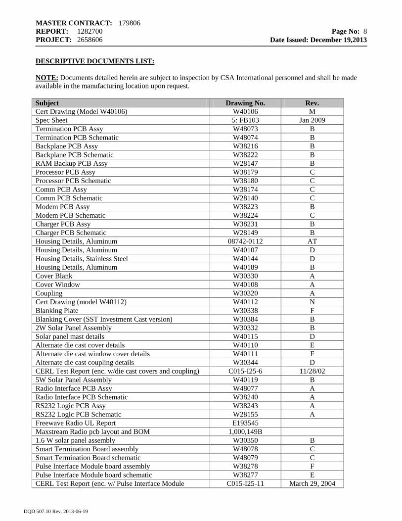
DESCRIPTIVE DOCUMENTS LIST: NOTE: Documents detailed herein are subject to inspection by CSA International personnel and shall be made available in the manufacturing location upon request. Subject Drawing No. Rev. Cert Drawing (Model W40106) W40106 M Spec Sheet 5: FB103 Jan 2009 Termination PCB Assy W48073 B Termination PCB Schematic W48074 B Backplane PCB Assy W38216 B Backplane PCB Schematic W38222 B RAM Backup PCB Assy W28147 B Processor PCB Assy W38179 C Processor PCB Schematic W38180 C Comm PCB Assy W38174 C Comm PCB Schematic W28140 C Modem PCB Assy W38223 B Modem PCB Schematic W38224 C Charger PCB Assy W38231 B Charger PCB Schematic W28149 B Housing Details, Aluminum 08742-0112 AT Housing Details, Aluminum W40107 D Housing Details, Stainless Steel W40144 D Housing Details, Aluminum W40189 B Cover Blank W30330 A Cover Window W40108 A Coupling W30320 A Cert Drawing (model W40112) W40112 N Blanking Plate W30338 F Blanking Cover (SST Investment Cast version) W30384 B 2W Solar Panel Assembly W30332 B Solar panel mast details W40115 D Alternate die cast cover details W40110 E Alternate die cast window cover details W40111 F Alternate die cast coupling details W30344 D CERL Test Report (enc. w/die cast covers and coupling) C015-I25-6 11/28/02 5W Solar Panel Assembly W40119 B Radio Interface PCB Assy W48077 A Radio Interface PCB Schematic W38240 A RS232 Logic PCB Assy W38243 A RS232 Logic PCB Schematic W28155 A Freewave Radio UL Report E193545 Maxstream Radio pcb layout and BOM 1,000,149B 1.6 W solar panel assembly W30350 B Smart Termination Board assembly W48078 C Smart Termination Board schematic W48079 C Pulse Interface Module board assembly W38278 F Pulse Interface Module board schematic W38277 E CERL Test Report (enc. w/ Pulse Interface Module C015-I25-11 March 29, 2004
DQD 507.10 Rev. 2013-06-19
MASTER CONTRACT: 179806 REPORT: 1282700 PROJECT: 2658606
Page No: 9
Date Issued: December 19,2013
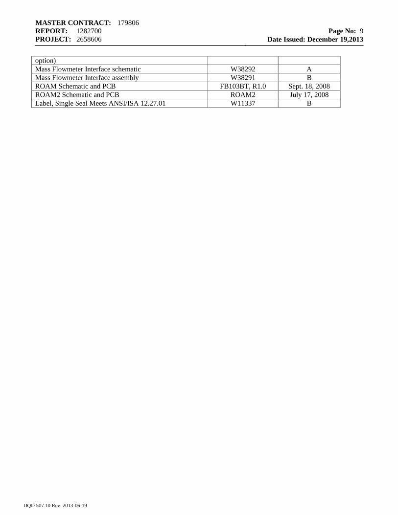
option) Mass Flowmeter Interface schematic W38292 A Mass Flowmeter Interface assembly W38291 B ROAM Schematic and PCB FB103BT, R1.0 Sept. 18, 2008 ROAM2 Schematic and PCB ROAM2 July 17, 2008 Label, Single Seal Meets ANSI/ISA 12.27.01 W11337 B
DQD 507.10 Rev. 2013-06-19
MASTER CONTRACT: 179806 REPORT: 1282700 PROJECT: 2658606
Page No: 10
Date Issued: December 19,2013
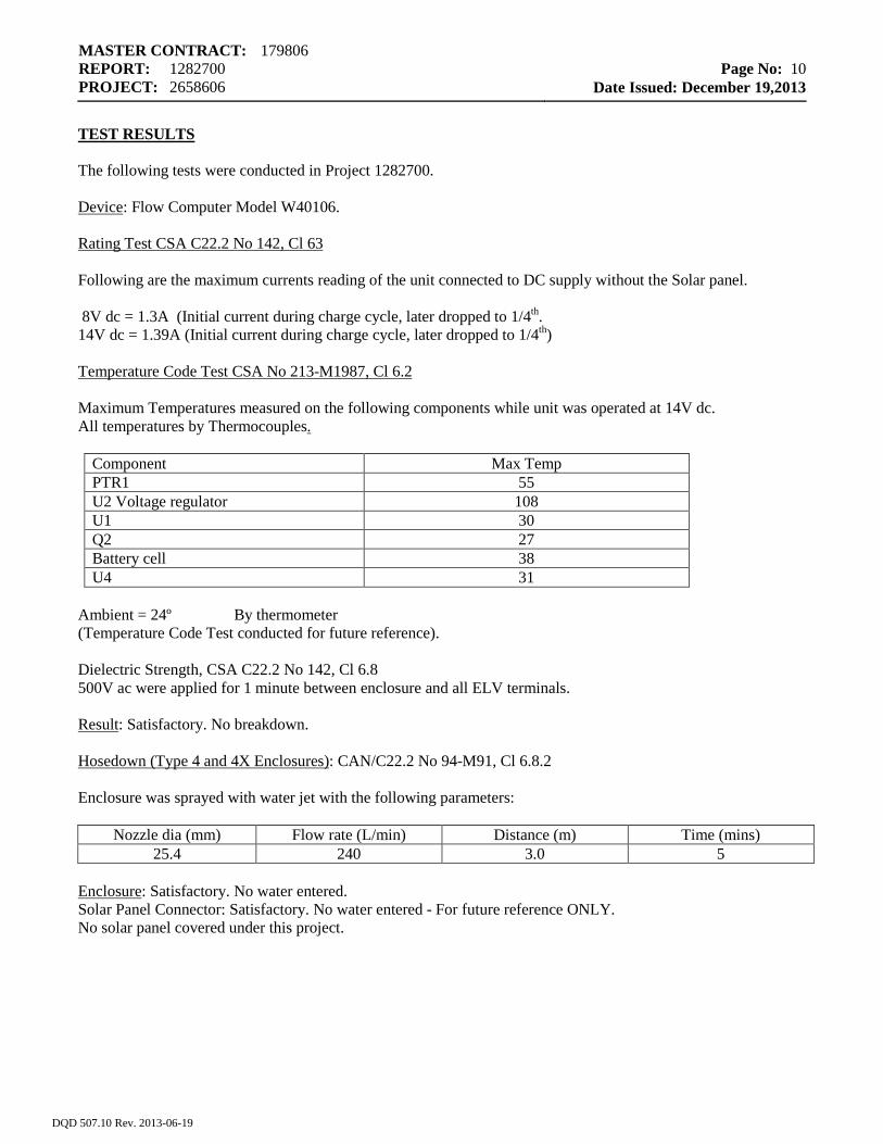
TEST RESULTS The following tests were conducted in Project 1282700. Device: Flow Computer Model W40106. Rating Test CSA C22.2 No 142, Cl 63 Following are the maximum currents reading of the unit connected to DC supply without the Solar panel. 8V dc = 1.3A (Initial current during charge cycle, later dropped to 1/4th. 14V dc = 1.39A (Initial current during charge cycle, later dropped to 1/4th) Temperature Code Test CSA No 213-M1987, Cl 6.2 Maximum Temperatures measured on the following components while unit was operated at 14V dc. All temperatures by Thermocouples.
Component Max Temp PTR1 55 U2 Voltage regulator 108 U1 30 Q2 27 Battery cell 38 U4 31
Ambient = 24º By thermometer (Temperature Code Test conducted for future reference). Dielectric Strength, CSA C22.2 No 142, Cl 6.8 500V ac were applied for 1 minute between enclosure and all ELV terminals. Result: Satisfactory. No breakdown. Hosedown (Type 4 and 4X Enclosures): CAN/C22.2 No 94-M91, Cl 6.8.2 Enclosure was sprayed with water jet with the following parameters:
Nozzle dia (mm) Flow rate (L/min) Distance (m) Time (mins) 25.4 240 3.0 5
Enclosure: Satisfactory. No water entered. Solar Panel Connector: Satisfactory. No water entered - For future reference ONLY. No solar panel covered under this project.
DQD 507.10 Rev. 2013-06-19
MASTER CONTRACT: 179806 REPORT: 1282700 PROJECT: 2658606
Page No: 11
Date Issued: December 19,2013
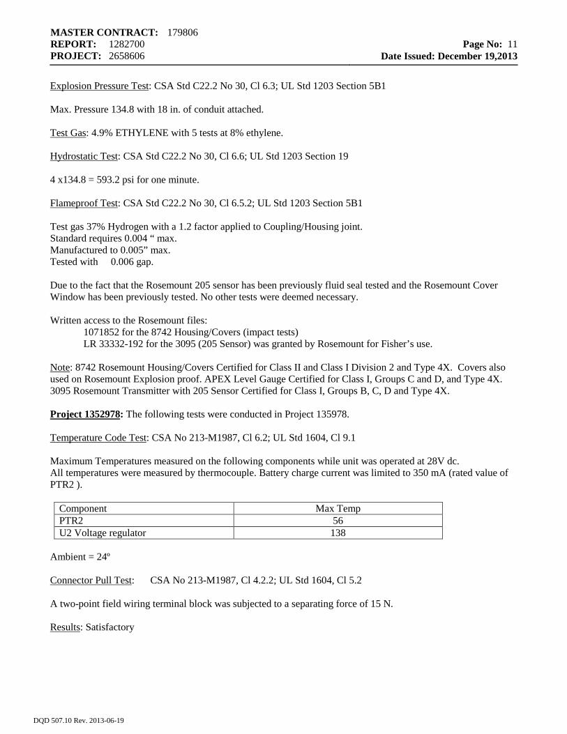
Explosion Pressure Test: CSA Std C22.2 No 30, Cl 6.3; UL Std 1203 Section 5B1 Max. Pressure 134.8 with 18 in. of conduit attached. Test Gas: 4.9% ETHYLENE with 5 tests at 8% ethylene. Hydrostatic Test: CSA Std C22.2 No 30, Cl 6.6; UL Std 1203 Section 19 4 x134.8 = 593.2 psi for one minute. Flameproof Test: CSA Std C22.2 No 30, Cl 6.5.2; UL Std 1203 Section 5B1 Test gas 37% Hydrogen with a 1.2 factor applied to Coupling/Housing joint. Standard requires 0.004 “ max. Manufactured to 0.005” max. Tested with 0.006 gap. Due to the fact that the Rosemount 205 sensor has been previously fluid seal tested and the Rosemount Cover Window has been previously tested. No other tests were deemed necessary. Written access to the Rosemount files: 1071852 for the 8742 Housing/Covers (impact tests) LR 33332-192 for the 3095 (205 Sensor) was granted by Rosemount for Fisher’s use. Note: 8742 Rosemount Housing/Covers Certified for Class II and Class I Division 2 and Type 4X. Covers also used on Rosemount Explosion proof. APEX Level Gauge Certified for Class I, Groups C and D, and Type 4X. 3095 Rosemount Transmitter with 205 Sensor Certified for Class I, Groups B, C, D and Type 4X. Project 1352978: The following tests were conducted in Project 135978. Temperature Code Test: CSA No 213-M1987, Cl 6.2; UL Std 1604, Cl 9.1 Maximum Temperatures measured on the following components while unit was operated at 28V dc. All temperatures were measured by thermocouple. Battery charge current was limited to 350 mA (rated value of PTR2 ).
Component Max Temp PTR2 56 U2 Voltage regulator 138
Ambient = 24º Connector Pull Test: CSA No 213-M1987, Cl 4.2.2; UL Std 1604, Cl 5.2 A two-point field wiring terminal block was subjected to a separating force of 15 N. Results: Satisfactory
DQD 507.10 Rev. 2013-06-19
MASTER CONTRACT: 179806 REPORT: 1282700 PROJECT: 2658606
Page No: 12
Date Issued: December 19,2013
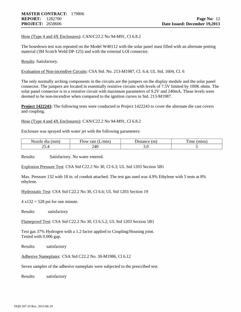
Hose (Type 4 and 4X Enclosures): CAN/C22.2 No 94-M91, Cl 6.8.2 The hosedown test was repeated on the Model W40112 with the solar panel mast filled with an alternate potting material (3M Scotch Weld DP-125) and with the external LOI connector. Results: Satisfactory. Evaluation of Non-incendive Circuits: CSA Std. No. 213-M1987, Cl. 6.4; UL Std. 1604, Cl. 6 The only normally arching components in the circuits are the jumpers on the display module and the solar panel connector. The jumpers are located in essentially resistive circuits with levels of 7.5V limited by 100K ohms. The solar panel connector is in a resistive circuit with maximum parameters of 9.2V and 240mA. These levels were deemed to be non-incendive when compared to the ignition curves in Std. 213-M1987. Project 1422243: The following tests were conducted in Project 1422243 to cover the alternate die cast covers and coupling. Hose (Type 4 and 4X Enclosures): CAN/C22.2 No 94-M91, Cl 6.8.2 Enclosure was sprayed with water jet with the following parameters:
Nozzle dia (mm) Flow rate (L/min) Distance (m) Time (mins) 25.4 240 3.0 5
Results: Satisfactory. No water entered. Explosion Pressure Test: CSA Std C22.2 No 30, Cl 6.3; UL Std 1203 Section 5B1 Max. Pressure 132 with 18 in. of conduit attached. The test gas used was 4.9% Ethylene with 5 tests at 8% ethylene. Hydrostatic Test: CSA Std C22.2 No 30, Cl 6.6; UL Std 1203 Section 19 4 x132 = 528 psi for one minute. Results: satisfactory Flameproof Test: CSA Std C22.2 No 30, Cl 6.5.2; UL Std 1203 Section 5B1 Test gas 37% Hydrogen with a 1.2 factor applied to Coupling/Housing joint. Tested with 0.006 gap. Results: satisfactory Adhesive Nameplates: CSA Std C22.2 No. 30-M1986, Cl 6.12 Seven samples of the adhesive nameplate were subjected to the prescribed test. Results: satisfactory
DQD 507.10 Rev. 2013-06-19
MASTER CONTRACT: 179806 REPORT: 1282700 PROJECT: 2658606
Page No: 13
Date Issued: December 19,2013
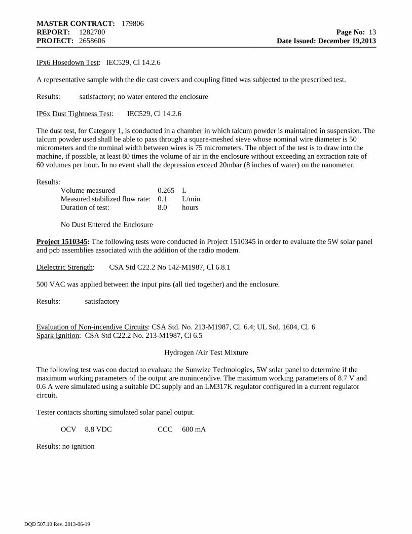
IPx6 Hosedown Test: IEC529, Cl 14.2.6 A representative sample with the die cast covers and coupling fitted was subjected to the prescribed test. Results: satisfactory; no water entered the enclosure IP6x Dust Tightness Test: IEC529, Cl 14.2.6 The dust test, for Category 1, is conducted in a chamber in which talcum powder is maintained in suspension. The talcum powder used shall be able to pass through a square-meshed sieve whose nominal wire diameter is 50 micrometers and the nominal width between wires is 75 micrometers. The object of the test is to draw into the machine, if possible, at least 80 times the volume of air in the enclosure without exceeding an extraction rate of 60 volumes per hour. In no event shall the depression exceed 20mbar (8 inches of water) on the nanometer. Results:
Volume measured 0.265 L Measured stabilized flow rate: 0.1 L/min. Duration of test: 8.0 hours
No Dust Entered the Enclosure
Project 1510345: The following tests were conducted in Project 1510345 in order to evaluate the 5W solar panel and pcb assemblies associated with the addition of the radio modem. Dielectric Strength: CSA Std C22.2 No 142-M1987, Cl 6.8.1 500 VAC was applied between the input pins (all tied together) and the enclosure. Results: satisfactory Evaluation of Non-incendive Circuits: CSA Std. No. 213-M1987, Cl. 6.4; UL Std. 1604, Cl. 6 Spark Ignition: CSA Std C22.2 No. 213-M1987, Cl 6.5
Hydrogen /Air Test Mixture The following test was con ducted to evaluate the Sunwize Technologies, 5W solar panel to determine if the maximum working parameters of the output are nonincendive. The maximum working parameters of 8.7 V and 0.6 A were simulated using a suitable DC supply and an LM317K regulator configured in a current regulator circuit.
Tester contacts shorting simulated solar panel output.
OCV 8.8 VDC CCC 600 mA Results: no ignition
DQD 507.10 Rev. 2013-06-19
MASTER CONTRACT: 179806 REPORT: 1282700 PROJECT: 2658606
Page No: 14
Date Issued: December 19,2013
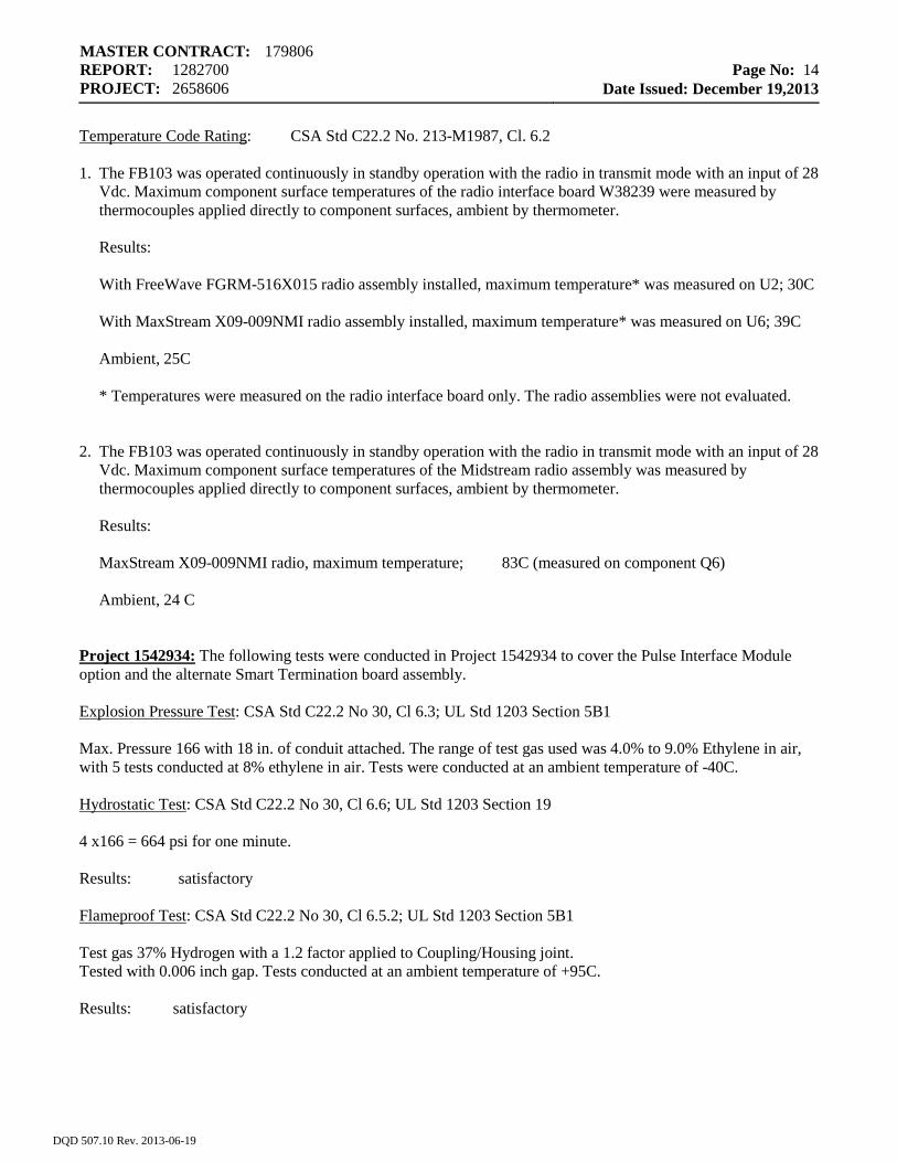
Temperature Code Rating: CSA Std C22.2 No. 213-M1987, Cl. 6.2 1. The FB103 was operated continuously in standby operation with the radio in transmit mode with an input of 28
Vdc. Maximum component surface temperatures of the radio interface board W38239 were measured by thermocouples applied directly to component surfaces, ambient by thermometer.
Results: With FreeWave FGRM-516X015 radio assembly installed, maximum temperature* was measured on U2; 30C With MaxStream X09-009NMI radio assembly installed, maximum temperature* was measured on U6; 39C Ambient, 25C * Temperatures were measured on the radio interface board only. The radio assemblies were not evaluated. 2. The FB103 was operated continuously in standby operation with the radio in transmit mode with an input of 28
Vdc. Maximum component surface temperatures of the Midstream radio assembly was measured by thermocouples applied directly to component surfaces, ambient by thermometer.
Results: MaxStream X09-009NMI radio, maximum temperature; 83C (measured on component Q6) Ambient, 24 C Project 1542934: The following tests were conducted in Project 1542934 to cover the Pulse Interface Module option and the alternate Smart Termination board assembly. Explosion Pressure Test: CSA Std C22.2 No 30, Cl 6.3; UL Std 1203 Section 5B1 Max. Pressure 166 with 18 in. of conduit attached. The range of test gas used was 4.0% to 9.0% Ethylene in air, with 5 tests conducted at 8% ethylene in air. Tests were conducted at an ambient temperature of -40C. Hydrostatic Test: CSA Std C22.2 No 30, Cl 6.6; UL Std 1203 Section 19 4 x166 = 664 psi for one minute. Results: satisfactory Flameproof Test: CSA Std C22.2 No 30, Cl 6.5.2; UL Std 1203 Section 5B1 Test gas 37% Hydrogen with a 1.2 factor applied to Coupling/Housing joint. Tested with 0.006 inch gap. Tests conducted at an ambient temperature of +95C. Results: satisfactory
DQD 507.10 Rev. 2013-06-19
MASTER CONTRACT: 179806 REPORT: 1282700 PROJECT: 2658606
Page No: 15
Date Issued: December 19,2013
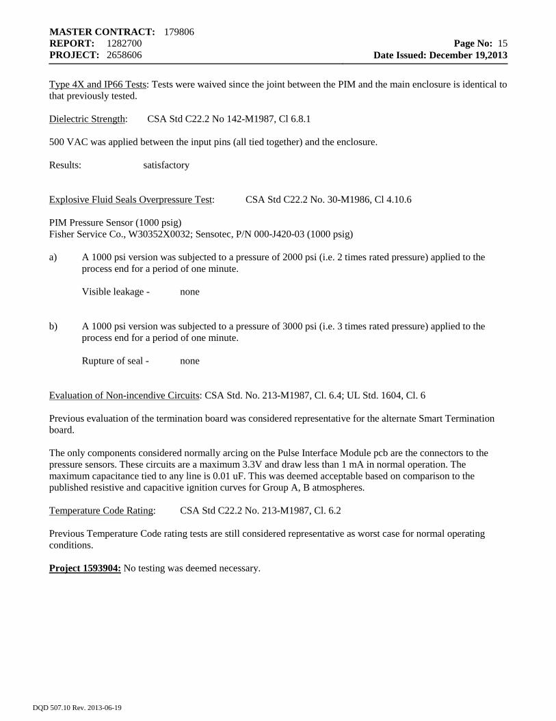
Type 4X and IP66 Tests: Tests were waived since the joint between the PIM and the main enclosure is identical to that previously tested. Dielectric Strength: CSA Std C22.2 No 142-M1987, Cl 6.8.1 500 VAC was applied between the input pins (all tied together) and the enclosure. Results: satisfactory Explosive Fluid Seals Overpressure Test: CSA Std C22.2 No. 30-M1986, Cl 4.10.6 PIM Pressure Sensor (1000 psig) Fisher Service Co., W30352X0032; Sensotec, P/N 000-J420-03 (1000 psig) a) A 1000 psi version was subjected to a pressure of 2000 psi (i.e. 2 times rated pressure) applied to the
process end for a period of one minute. Visible leakage - none b) A 1000 psi version was subjected to a pressure of 3000 psi (i.e. 3 times rated pressure) applied to the
process end for a period of one minute. Rupture of seal - none Evaluation of Non-incendive Circuits: CSA Std. No. 213-M1987, Cl. 6.4; UL Std. 1604, Cl. 6 Previous evaluation of the termination board was considered representative for the alternate Smart Termination board. The only components considered normally arcing on the Pulse Interface Module pcb are the connectors to the pressure sensors. These circuits are a maximum 3.3V and draw less than 1 mA in normal operation. The maximum capacitance tied to any line is 0.01 uF. This was deemed acceptable based on comparison to the published resistive and capacitive ignition curves for Group A, B atmospheres. Temperature Code Rating: CSA Std C22.2 No. 213-M1987, Cl. 6.2 Previous Temperature Code rating tests are still considered representative as worst case for normal operating conditions. Project 1593904: No testing was deemed necessary.
DQD 507.10 Rev. 2013-06-19
MASTER CONTRACT: 179806 REPORT: 1282700 PROJECT: 2658606
Page No: 16
Date Issued: December 19,2013
Project 1648330: The following test was conducted to evaluate the W40112 assembly with the added MVD Interface board. All other previous testing was deemed representative as worst case. Dielectric Strength: CSA Std C22.2 No 142-M1987, Cl 6.8.1 500 VAC was applied between the input pins (all tied together) of the MVD Interface board and the enclosure. Results: satisfactory Project 1800071: The following test was conducted to evaluate the W40112 assembly with the alternative external LOI connector. All other previous testing was deemed representative as worst case. Hose (Type 4 and 4X Enclosures): CAN/C22.2 No 94-M91, Cl 6.8.2, UL Std. 50, sec. 35 The hosedown test was repeated on the Model W40112 with the alternative external LOI connector. Results: Satisfactory. Project 1934252: Under Project 1934252, a 316 SST version of the enclosure was added. Due to the superior tensile and yield strength of 316 SST compared to the original aluminum alloy, no further testing was deemed necessary. In addition, under this project, a thinner version of the Blanking Cover (Refer to Dwg. W30384) was evaluated and tested for the model W40106. This version of the Blanking Cover is an investment cast stainless steel design with a thinner wall thickness than the originally evaluated/tested Blanking Cover. As a result, the following test was considered necessary: Hydrostatic Test: CSA Std. C22.2 No 30, Cl 6.6 UL Std. 1203, 4th Ed., Section 19 Device: Model W40106, with “investment cast” SST Blanking Cover (Dwg. W30384) installed.
Type: "Type". Test Pressure: 664 psi (ie. 4 times worst case measured pressure of 166 psi – from Pressure Determination Tests conducted under Project 1542934) Duration: 1 min.
Results: No rupture or permanent deformation, nor elongation of fasteners – Satisfactory. Project 2099135: Update Report 1282700 to include the addition of Remote Operator Access Module (ROAM) to the FloBoss 103 and 104 Flow Manager. Note: The FloBoss 103 and 104 Flow Manager Products are as follows: Model W40106 is the Division 1/2 version of the FloBoss 103/104. Model W40112 is the Division 2 only version of the FloBoss 103/104. Following Tests Deemed necessary: Note: All testing done with the ROAM module installed in the FloBoss 103 and communicating with a PDA
supplied by Fisher. Complete test results can found in Documentum. Marked Electrical Rating: C22.2 No. 142, Clause 6.3
DQD 507.10 Rev. 2013-06-19
MASTER CONTRACT: 179806 REPORT: 1282700 PROJECT: 2658606
Page No: 17
Date Issued: December 19,2013
Results: Satisfactory Temperature Test: C22.2 No. 213, Clause 6.2; ANSI/ISA 12.12.01, Clause 10.1 Results: Satisfactory, did not affect the Tcodes stated within this report. Dielectric Strength Test: C22.2 No. 142, Clause 6.8.1; UL 508, Clause 49.1.2 (a) Results: Satisfactory 15 Newton Pull Test: C22.2 No. 213, Clause 4.2.2; ANSI/ISA 12.12.01, Clause 8.2 Results: Satisfactory No further testing deemed necessary. Project 2129567: Update Report 1282700 to include the addition of Remote Operator Access Module (ROAM2) to the FloBoss 103 and 104 Flow Manager. Note: Corrected clerical error identifying FloBoss 103 and 104 to the correct model W40106 and W40112 regarding Division 1 and 2 on edition 10 (Project 2099135). Note: The FloBoss 103 and 104 Flow Manager Products are as follows: Model W40106 is the Division 1/2 version of the FloBoss 103/104. Model W40112 is the Division 2 only version of the FloBoss 103/104. Following Tests Deemed necessary: Note: All testing done with the ROAM2 module installed in the FloBoss 103 and communicating with a PDA
supplied by Fisher. Complete test results can found in Documentum. Marked Electrical Rating: C22.2 No. 142, Clause 6.3 Results: Satisfactory Temperature Test: C22.2 No. 213, Clause 6.2; ANSI/ISA 12.12.01, Clause 10.1 Results: Satisfactory; did not affect the Tcodes stated within this report. Dielectric Strength Test: C22.2 No. 142, Clause 6.8.1; UL 508, Clause 49.1.2 (a) Results: Satisfactory 15 Newton Pull Test: C22.2 No. 213, Clause 4.2.2; ANSI/ISA 12.12.01, Clause 8.2 Results: USB Connector (ROAM2 Module) - Compliance: NO; Refer Non-Incendive Evaluation J2 ROAM2 Module After temperature Test - Compliance: NO; Refer Non-Incendive Evaluation
DQD 507.10 Rev. 2013-06-19
MASTER CONTRACT: 179806 REPORT: 1282700 PROJECT: 2658606
Page No: 18
Date Issued: December 19,2013
Non Incendive Evaluation: C22.2 No. 213, Clause 4.2.2; ANSI/ISA 12.12.01, Clause 8.2 Results: Satisfactory No further testing deemed necessary. Project 2153434: The “Direct Mount” sensor assembly when used in the construction of models W40106 and W40112 flow computers uses the same Rosemount transducer p/n 205P or 205E which is used with Rosemount’s model 3095 transmitter (CSA certified under CSA report 1476733). The Rosemount transmitter was evaluated to the ANSI/ISA 12.27.01 std., a copy of the test results are listed below; (For complete test results, see Reports LR2303-01, ER37895-2 Rev1, and, LR2298-01 (included in Documentum bin “Tests folder” under the current Project 2153434)).
Clause 6.2.2 - Temperature cycling: Temperature Cycling on two representative samples was conducted between -54 and 166°C for a duration of 15.8 days. Clause 6.2.3 - Fatigue Cycling: Representative samples were subjected to a total of 100,000 (Min) cycles between 0 and 3626 psig at an ambient temperature of 300°F as required by ANSI/ISA 12.27.01. Clause 6.2.4 - Process Seal Leakage Test: A leakage test was conducted. The minimum leakage pressure required was 6853 PSI. The samples successfully passed a pressure test of 7040 PSI without leakage. Clause 6.2.5 - Process Seal Rupture Test: A Rupture test was conducted. The minimum rupture pressure required was 10,080 PSI. The samples successfully passed a pressure test of 10,600 PSI without rupture. The suitability of the process seal material for the specific process fluid is the responsibility of the manufacturer.
Adhesive label tests were not considered necessary as the same label material was previously accepted in CSA Report 1282700. No further testing or evaluation was deemed necessary.
DQD 507.10 Rev. 2013-06-19

MASTER CONTRACT: 179806 REPORT: 1282700 PROJECT: 2658606
Page No: 19
Date Issued: December 19,2013
Edition 13 (Project 2225713): This project was opened to allow another manufacturing facility to make the aluminum die cast electronics housing per drawing W40189 as requested by the customer. Based upon similarities between W40189 to previous housings accepted under this report, no testing deemed necessary. Drawing W40144 has been added to the descriptive documents per it’s acceptance in the certification drawing W40106 previously accepted. The following drawings have been added/ updated under this report:
Drawing Number Old Rev New Rev W40106 K L 5: FB103 May 2008 Jan 2009 W40112 L M W40144 - D W40189 - A
(Project 2658606): 1. Modification and changes on drawings The following table contains a brief explanation of drawing changes:
Drawing # Rev change Description
W40112 M to N Drawing change that does not affect the safety of the product.
W40106 L to M Drawing changes that do not affect the safety of the product.
W38277 D to E SCH: Changing MPU
W38278 E to F BOM: Changing MPU, Omitting software combination X0012,X0022 adding X0032 W40189 A to B Connection shape of Bolt lugs in housing is changed need hydrostatic test
W20344 C to D Add two holes to the sensor housing as a place to clip for sensor change that does not affect the safety of the product.
W40118 B to C Upper level drawing of W20344D 2. Housing flange shape change:
On model W40106 there is no change in enclosure volume, but based on change on bolt lugs in housing to a hydrostatic test conducted. Hydrostatic Test: CSA Std. C22.2 No 30, Cl. 6.6; UL Std. 1203 Section 19 4 x166 = 664 psi for one minute. (ie. 4 times worst case measured pressure of 166 psi – from Pressure Determination Tests conducted under Project 1542934) Results: Satisfactory (no leak or rupture observed) No further test requires
End of the report.
DQD 507.10 Rev. 2013-06-19