Embed Size (px)
Citation preview

Z17 Coalescer Manual
If you have any questions or require product support, please contact 888.249.4855
Zebra Z17 Coalescer ManualINSTALLATION, OPERATION AND MAINTENANCE
CoolantMaintenance.comfor clean coolant tips
Copyright 2013 © ZSCZebra Skimmers Corp.
PO Box 833Chagrin Falls, OH 44022
888.249.4855www.ZebraSkimmers.com
Printed in the USA • Revised October 2013
Information is correct as of the date printed. We reserve the right to change any information without notice.
Z17 Coalescer Manual
www.ZebraSkimmers.com 2
VERY IMPORTANT INFORMATION
DETERMINING IF THE Z17 COALESCER WILL WORK FOR YOU
While the Z17 Coalescer functions in a wide variety of environments, it is not engineered to work in sumps that contain coolant soaps (grease) or emulsified oils.
We recommend you perform a ‘shake test’ with your sump fluid prior to installing the Z17. Fill a 16 oz clear bottle to three quarters full with fluid from your sump, shake the bottle vigorously for a minute and then let it rest for 15 minutes. If after 15 minutes a distinct layer of oil forms on the surface of the fluid, then the Z17 is likely a good fit for your sump.
If a layer of oil does not form on the surface of the liquid in the bottle the Z17 will not function properly on your sump, contact your distributor to discuss a Zebra product better suited to your particular situation.
Assembly Warnings
HAND TIGHTEN the drum faucet, coolant discharge tubing and T-Strainer to the barrel spin welds. Over tightening will damage threads. Also, be careful not to cross-thread any fittings.
DO NOT push, pull or lift the Z17 by the T-Strainer and/or drum faucet, doing so can crack the spin weld fittings and void your warranty.
Place the clean coolant return hose on the opposite side of the sump, as far away from the intake attach-ment as possible.
!

3 Zebra Skimmers Corp.Z17 Coalescer
Z17 Coalescer Manual
Copyright 2013 © ZSC • Zebra Skimmers Corp.
All standard Zebra products come with a minimum one year warranty. Any use of our products outside of suggested parameters voids all warranties. Pricing and other information subject to change without notice. All trademarks of Zebra Skimmers Corporation are listed at Zebra-US.com. All Zebra Skimmers Corporation registered marks and trademarks used in this catalog are protected by U.S. and international law.
Table of Contents
Chapter 1 - Introduction ......................................................... 4
Chapter 2 - Precautionary Safety Measures ......................... 6
Chapter 3 - Exploded Parts Diagrams ................................... 7
Chapter 4 - Assembly and Installation Guidelines ............... 8
Chapter 5 - Operation and Maintenance Guidelines ......... 16
Chapter 6 - Troubleshooting the System ............................. 20
Appendices ............................................................................ 21
Z17 Coalescer Manual
www.ZebraSkimmers.com 4
Calling Customer Support
If you have difficulty assembling this product or have any questions regarding the controls, operation, or maintenance of this unit, please call the Customer Support Line at 888.249.4855.
For the latest details about Zebra portable coalescers you can also visit our web site at www.ZebraSkimmers.com.
For current updates to this manual, please visit
http://www.zebraskimmers.com/product_literature_video.html

5 Zebra Skimmers Corp.Z17 Coalescer
Z17 Coalescer Manual
Chapter 1 - Introduction
1.1 Introduction to Your Z17 Coalescer
Thank you for purchasing the Zebra Muscle Coalescing System to meet your coolant maintenance chal-lenges.
This system is designed to run continuously on an individual sump, removing tramp oils and automati-cally aerating your coolant to prevent bacterial growth. The system may service multiple sumps if using the air diaphragm pump. However, individual sumps will only be circulated, aerated, and filtered when the Muscle is servicing that particular sump.
The Muscle’s coalescing media will accelerate the oil separation process, handling all oils that gravity separate from the coolant within approximately 10 minutes or less.
The Flexor surface skimmer concentrates the separated oils within the coalescing cylinder, for manual discharge through the external spigot, to your oil collection container. For best results, discharge the oil when it is a few inches thick to minimize coolant loss. Once the system is in operation a few days, you will have a better idea how much oil accumulates in the coalescer and when to drain it off.
The standard 170 micron t-strainer separates lightly suspended solids. It is recommended to clean the filter when it is full and/or hinders the approximate 2 gpm flow rate of the system. Zebra offers a larger capacity filter with a 75micron stainless steel cartridge purchased separately.
Zebra offers 4’ of both main intake hose and discharge hose, standard. 10’ of intake hose and/or 8’ of discharge hose are available, purchased separately.
An optional drum dolly is also available for ease of movement in and around your shop, whether for rou-tine machine tool maintenance or multiple sump servicing.
1.2 Limited Warranty Information
The Zebra Muscle Flexor Coalescer is warranted for two years from date of purchase against manufac-turing or material defects, except for disposable elements. Individual warranties may apply to third party components, above and beyond this expressed warranty. This warranty will be void, in full or in part, for any use not in keeping with general safe operating procedures or any of those principles outlined in this manual.
THE ABOVE WARRANTY IS EXCLUSIVE AND IN LIEU OF ALL OTHER WARRANTIES, WHETHER EX-PRESSED OR IMPLIED, INCLUDING THE IMPLIED WARRANTIES OF MERCHANTABILITY, FITNESS FOR A PARTICULAR PURPOSE AND NON-INFRINGEMENT. THIS WARRANTY GIVES YOU SPECIFIC LEGAL RIGHTS. YOU MAY HAVE OTHER RIGHTS, WHICH VARY FROM STATE TO STATE.
Zebra Skimmers Corp. (ZSC) has made every attempt in earnest and good faith to make this manual as comprehensive, complete and detailed as possible. However, all information contained herein is subject

Z17 Coalescer Manual
www.ZebraSkimmers.com 6
to change without notice at the sole discretion of ZSC, or at the discretion of third party vendors whose in-formation has been reprinted herein. ZSC is not liable for any damages which may or may not be caused by improper use of this equipment, as explicitly stated within this operator’s manual. Furthermore, ZSC is not liable for the quality of information that may be contained in, or unintentionally omitted from this manual. ZSC will repair or replace such defective components at its sole discretion. Customer must pay for shipping any parts or the entire Zebra Muscle™ to or from ZSC repair facilities, at the sole discretion of ZSC. Zebra Muscle™, Flexor™, Recept™, Sumpster™, and Hammerhead™ are wholly owned trade-marks of the Zebra Skimmers Corporation.
1.3 Contacting Customer Support
If you would like any assistance in assembly or installation of this system, or have any questions on its use or maintenance, please contact customer support at 888-249-4855. We will be glad to help you and welcome your feedback.
For the latest product details, please visit our web site www.ZebraSkimmers.com.
1.4 Z17 Flexor Muscle Standard Parts
Standard items included with your Z17 Flexor Muscle
• 15 Gallon Drum with lid (qty 1)
• Drum ring (qty 1)
• 4’ discharge hose (qty 1)
• Drum faucet (qty 1)
Parts Kit which includes the following:
• Submersible Pump with modified volute (qty 1)
• 4’ intake hose (qty 1)
• T-Strainer with BLUE flow restrictor (.125”) installed in discharge (qty 1)
• Flow restrictors - 1 GREEN (.25”) and 1 ORANGE (.5”)
• Black elbow fittings (qty 1)
• Black straight fitting (qty 1)
• Compression clamps (qty 2)
Skimmer Attachment
One of the following; hammerhead, recept, sumpster or floating sumpster.
7 Zebra Skimmers Corp.Z17 Coalescer
Z17 Coalescer Manual
Chapter 2 - Precautionary Safety Measures
2.1 Precautionary Safety Measures
WARNING: Read, understand, and follow all instructions contained in this manual before starting. Keep this manual in a safe, yet convenient, place for future reference.
WARNING: Failure to comply with all installation, operating, and maintenance guidelines will void all warranties, may cause damage to the unit, or cause personal injury.
WARNING: It is the responsibility of the user to only allow individuals familiar with, and with full knowledge of, this unit to install, operate, and maintain it. Zebra Skimmers Corp. will not be liable for any damages due to lack of proper use of this equipment.
WARNING: Make sure you have the MSDS for your coolant on file, and documentation related to its mixing, measuring, maintenance, and disposal are read and understood. If you have any questions regarding your specific coolant, contact your coolant supplier’s technical support service.
WARNING: Care must be taken at all times when handling coolant and waste oils. This in-cludes utilizing safety glasses with side shield protection, gloves, long sleeved shirts and long-legged pants. Sturdy shoes should also be worn, preferably with reinforced toes. Any liquids that come into contact with the skin should be washed off with mild soap as soon as possible. Liquid that comes into contact with the eyes should be washed out im-mediately with water only.
WARNING: Tramp oils floating on coolant promote growth of anaerobic bacteria. These bacteria create noxious gases, such as hydrogen sulfide (H2S) and hydrochloric acid (HCl). Hydrogen sulfide causes unpleasant odors. Hydrochloric acid, however, can cause skin, eye, and lung irritation. If these symptoms are present, consult a physician. Use the Zebra Muscle Coalescer in a well- ventilated area to prevent these symptoms, should these gas-es be present.
WARNING: Waste oil is hazardous and should be handled accordingly. Observe all prop-er national and local disposal laws and regulations.
WARNING: Do not operate this equipment while under the influence of drugs or alcohol.
WARNING: Do not put hands or feet in the barrel of this unit.
WARNING: While moving this equipment, slow down before turning corners to prevent tippage. To prevent spillage, do not move the unit over hoses, mats, or other floor obstruc-tions.

Z17 Coalescer Manual
www.ZebraSkimmers.com 8
Chapter 3 - Exploded Parts Diagrams
3.1 Coalescer Body Exploded Parts Diagram
1 Coalescer Barrel, 15 gallon (Z17MAIN)2 Oil Discharge Spigot (FXODF)3 T-Strainer (FMXTS1), 170µ, std. (larger capacity 75µ pore
size option purchased separately - F17X1)4 Clear braided hose 1/2” ID (SK97)5 Submersible Pump (FXP11)6 Pump Suction Hose, black flexible (SK99)7 Clean Coolant Return Hose (4’ std, 10’ option purchased
separately)(SK95)
8 Sumpster Intake Attachment (SK10A7)9 Hammerhead Intake Attachment (SK02D12F)10 Recept Intake Attachment (SK07R1.2)11 Floating Sumpster Intake Attachment (SK10B2)
NOT SHOWNCoalescing Media (non-consumable) FXCM003Drum Dolly FXDD15
* The Coalescer is supplied with 4 feet of dirty
coolant intake and clean coolant discharge hose,
standard. Should your application require more
hose, the Muscle can be equipped with up to 15
feet of intake hose and up to 8 feet of discharge
hose. The pump suction hose is at its maximum
length, standard.

9 Zebra Skimmers Corp.Z17 Coalescer
Z17 Coalescer Manual
Chapter 4 - Assembly and Installation Guidelines
4.1 Coalescer Body and Parts Kit1. Identify Coalescer Body and Parts Bag have been received with matching identification item numbers.
2. Verify that the model number of your unit, which is located on the outer shrink wrap label, matches what you ordered.
3. Remove the packing material from inside the barrel.
4. Screw the oil discharge spigot into the bulkhead fitting. Hand tighten so the spout is facing downward.
5. Check that the flow restrictor nipple assembly with the BLUE band is threaded into the T-Strainer. At-tach the 90° elbow fitting to the inlet side of the “T”-Strainer and then attach “T”-Strainer sub assembly to barrel. Confirm that the direction of the flow arrow on the “T”-Strainer is pointing toward the barrel.
6. Attach 1/2” ID clear braided hose (clamps provided) to the pump outlet.
7. Attach 1/2” ID black flexible hose to the pump inlet and intake attachment.
8. Attach 1 1/4” ID spiral wound coolant return hose to barrel.
9. Place the barrel next to your coolant sump so it is level and the oil discharge spigot is easily accessible. Make sure that the spigot is in a closed position.
10. Install your preferred tramp oil intake attachment and the pump. See instructions and diagrams for attachment details. Locate the attachment in an area where the oil naturally collects, if possible. Also make sure the discharge port of the pump (which has hose going to the barrel) is in an upright position to allow for any entrained air to escape. For baffled sumps, two attachments may be necessary, and a Y-fitting should be used for both to connect to the pump.
11. Place the clean coolant return hose on the opposite side of the sump, as far away from the intake attachment as possible. This will allow for proper surface oil flow to the intake attachment. Dis-charge hose should be installed and secured above the sump liquid level to prevent possible back pres-sure into the barrel. Also make sure this hose is in a continuous downward slope since the discharge is gravity fed.
12. Attach 1/2” ID clear braided hose (clamps provided) to the “ T”-Strainer.
13. Position the Eductor so the fluid splits the opening and fluid is drawn in. This position may be adjusted during oil discharge, if necessary.
14. If using a drum dolly, place the barrel upon it once the wheels have been attached.
15. Fill the barrel with fresh coolant, at the required concentration for the application, until it reaches the bottom of the Eductor (about 12 gallons).
16. Replace the lid on the barrel, and fasten the metal ring.
17. Plug the pump into an appropriate GFCI outlet and let the unit do its job.
CAUTION: Do not use the Muscle to service machine sumps that run different brands of coolant or the same brand of coolant, but at different concentrations. Also be aware of possible bacterial cross
contamination between sumps.

Z17 Coalescer Manual
www.ZebraSkimmers.com 10
4.2 Assembly Pictures

11 Zebra Skimmers Corp.Z17 Coalescer
Z17 Coalescer Manual
4.3 Submersible Pump
The submersible pump is no longer modified. Should you have an issue with your pump please call Support at 1-888-249-4855.
4.4 T-Strainer
The T-Strainer is shipped with the BLUE restrictor installed on the discharge side of the unit. Only hand tighten the T-Strainer into the coalescer body, over tightening may damage the spin weld fitting. Also, use caution to avoid cross threading when turning in the T-Strainer to the spin weld fitting.
It is good practice to clean the stainless steel mesh filter in the T-Strainer reservoir on a monthly basis. Unplug the submersible pump, remove and drain the T-Strainer reservoir, remove the mesh screen and rinse out contamination. Insert the mesh filter in the reservoir bowl and hand tighten onto the T-Strainer body. Plug in the submersible pump.
4.5 Flow Restrictors
The Z17 Muscle ships with three (3) flow restrictors, each restricts the flow of sump fluids into the coalescer to achieve an optimized separation of oil from the sump coolant mixture. The BLUE restrictor ships installed on the T-Strainer, the GREEN and ORANGE restrictors ship in the parts bag. To optimize oil separation, the fluid level in the center cartridge must be in the operating zone of the oil discharge weir. In most cases, the BLUE restrictor, pre-installed on the T-Strainer, is the best choice. However, due to differences in sump fluids and sump conditions, you may need to change restrictors to achieve opti-mal fluid levels in the center coalescing cartridge and a flow rate between 1 and 2 gallons per minute.
To change the flow restrictor follow these steps:
1. Unplug the Z17 Muscle pump
2. Remove the reservoir from the T-Strainer and empty coolant into the coaleser then hand tightenthe reservoir back onto the T-Strainer body
3. Remove the 1/2” braided hose from the inlet elbow on the T-Strainer

Z17 Coalescer Manual
www.ZebraSkimmers.com 12
4. Remove the T-Strainer assembly from the coalescer body
5. Protect the threads on the 1” nipple installed on the T-Strainer and remove the nipple
6. Thread the GREEN restrictor into the T-Strainer
7. Carefully thread the T-Strainer assembly onto the coalescer body -- be careful not to cross-threador over-tighten this assembly
8. Reattach the 1/2” braided hose to elbow on the T-Strainer and place the clamp
9. Plug in the pump
10. Monitor the center cartridge for optimal level. If the fluid level remains below the oil dischargeoperating level, repeat the process and install the ORANGE restrictor.
4.6 Z17 Muscle Basic Parts List
Standard items included with your Z17 Flexor Muscle
• 15 Gallon Drum with lid (qty 1)
• Drum ring (qty 1)
• 4’ discharge hose (qty 1)
• Drum faucet (qty 1)
Parts Kit which includes the following:
• Submersible Pump with modified volute (qty 1)
• 4’ intake hose (qty 1)
• T-Strainer with BLUE flow restrictor (.125”) installed on discharge side of strainer (qty 1)
• Flow restrictors - 1 GREEN (.25”) and 1 ORANGE (open)
• Black elbow fittings (qty 1)
• Black straight fitting (qty 1)
• Compression clamps (qty 2)

13 Zebra Skimmers Corp.Z17 Coalescer
Z17 Coalescer Manual
4.7 Skimmer Attachments
Hammerhead™ Installation
1. Unpack the Hammerhead.
2. Attach the 1/2” black flexible hose, via its straight fitting, to the intake port of the pump. Hand-tight-en only.
3. Attach the Hammerhead body to the opposite side of the flexible hose, turning no more than TWOTURNS. This will allow it to float properly.
4. Place both the pump and the Hammerhead into the sump. The Hammerhead should float on thesurface foam side up.
5. You may need to dip the Hammerhead below the liquid surface for a few minutes, to aid in pumppriming, when initially introducing it to the sump.
NOTE: The Hammerhead will handle a level fluctuation up to 12” only. We recommend use of the Floating Sumpster for all other applications.

Z17 Coalescer Manual
www.ZebraSkimmers.com 14
Recept™ Installation
1. Unpack the Recept.2. Attach the 1/2” black flexible hose, via its straight fitting, to the intake port of the pump. Hand-tight-
en only.3. Attach the Recept body to the opposite side of the flexible hose, hand tighten only.4. Place both the Pump and Recept into the sump. The Recept should float on the surface5. You may need to dip the Recept below the liquid surface for a few minutes to aid in pump priming
when initially introducing it to the sump.

15 Zebra Skimmers Corp.Z17 Coalescer
Z17 Coalescer Manual
Sumpster™ Installation
1. Unpack the Sumpster and its components.2. Connect the 1/2” braided hose to the intake port of the pump.3. Connect the opposite end of the braided hose to the back of the Sumpster box.4. The Sumpster can be mounted to the rod and crow’s feet, placed directly on the bottom of the
sump, or mounted on a sump side bracket.5. Place both the pump and the Sumpster into the sump.6. Adjust the height of the box by following the diagram below, positioning the top of the box 1/4”
above the maximum fluid level.
NOTE: The Sumpster will handle a level drop of 3” only. We recommend use of the Hammerhead if there is a 3-12” fluctuation, or the Floating Sumpster for all other applications.

Z17 Coalescer Manual
www.ZebraSkimmers.com 16
Floating Sumpster™ Installation
1. Unpack the Floating Sumpster.2. Connect the pump intake port directly to the back of the Sumpster box.3. Place the Floating Sumpster w/pump into the sump.4. Adjust the height of the box by following the diagram below, positioning the top of the box 1/4”
above the fluid level - adjust floats as necessary. Usually the pump side takes the lower floats. NOTE: The Floating Sumpster will handle a level fluctuation of up to 2’ with the use of the standard 4’ dirty coolant intake hose provided (4’ max lift with custom hose size).

17 Zebra Skimmers Corp.Z17 Coalescer
Z17 Coalescer Manual
Chapter 5 - Operation and Maintenance Guidelines
5.1 Usage of the Muscle Coalescer
The Muscle Coalescer has been designed to work continuously on one individual machine sump. It is recommended to operate this unit 24 hours per day, and 7 days per week, to keep the fluid circulating, preventing bacterial contamination.
The Hammerhead is rated to float on a 1/4” maximum depth oil layer. If your application currently has a thicker layer of oil on its surface and you are using the Hammerhead intake attachment, it may be neces-sary to manually hold the Hammerhead at the surface until the oil layer becomes less than 1/4” in depth.If you use this equipment for more than one machine, you may experience poor pump life, as it captures air, due to its reintroduction to various machine sumps. We recommend removing the intake attachment and capping off the intake hose before unplugging the pump in order to keep the pump primed with liq-uid.
If you are utilizing the Muscle on a high-pressure coolant delivery system (add-on equipment to your machine tool), you may experience a very low amount of separated oil. High pressure systems tend to emulsify tramp oils more deeply into coolant compared to standard delivery pumps, and generally re-quire more time than the Muscle allows for separation. If this situation occurs, it is best to operate the Muscle only when the machine pumps are shut down.
5.2 Adjusting the Oil Discharge Weir
Turn oil discharge weir clockwise to lower the unit and counter-clockwise to raise the unit. Adjust the weir to the height where only oil is drained from the center cartridge of the Z17 Muscle unit.
5.3 Use of the Oil Collection Chamber
The oil collection chamber extends from the bottom of the oil discharge weir to the drum faucet. The drum faucet is 15” above the bottom of the barrel. Open the drum faucet to discharge the oil collection chamber.

Z17 Coalescer Manual
www.ZebraSkimmers.com 18
5.4 Routine Inspection
Periodically inspect the intake attachment as well as its hose to make sure it is not clogged with chips or debris. Blockages cause stress on the pump and may totally impair the flow of the system. If there is a poor flow (less than 1 gpm) then it is likely that there is debris blocking the flow route.Be aware of the quality of the connection between the intake attachment and intake hose. If the connec-tion is loose, admits air, or is clogged, it will impair the function of the unit.On occasion, check to make sure that there is not an excessive buildup of debris in the bottom of the bar-rel. Excessive sediment will restrict the clean coolant return flow, causing the barrel to overflow or return debris to your tank.
Fully inspect the operation of the machine before leaving it unattended. Verify that the flow rate is normal and tank levels are maintained. All connections, filters, and hoses should be free of all possible obstruc-tions and airtight.
5.5 Routine Maintenance
INTAKE ATTACHMENTS (Hammerhead, Recept, Sumpster, or Floating Sumpster)If using the Sumpster intake attachment, you may need to periodically remove debris from the chip screen. To clean the screen, lift the door/float assembly, then remove, clean, and replace the screen as soon as possible to prevent debris from entering pump.
DRAINING TRAMP OIL
We recommend draining the accumulated oil layer within the Muscle barrel when it is at least 3” thick (10” maximum). This can be done while the Muscle is operating. Please a bucket beneath the discharge drum faucet which is 15” from bottom of coalescer. Open the spigot, letting the oil drain, until just a thin layer of oil is left, or coolant starts to flow out. NOTE: Only open drum faucet when draining contaminant oil. For best results, position Flexor to draw below surface to reduce aeration, repositioning once drained. Shut the spigot. In some cases, especially on high pressure coolant delivery systems, there will be an inverse layer which does not fully separate into tramp oil and coolant. It is best to discharge this highly emulsified layer as well.
This process will need to be repeated, as necessary, and will depend upon your situation. It is recom-mended to start a routine inspection on a by-shift basis, which will ensure that the layer is thick enough for draining, yet thin enough as to not encourage bacterial growth.
REPLACING THE PUMP
When replacing the pump, make sure the flow restrictor is contained in the intake hose which goes to the barrel. Removing it will cause the barrel to overflow.
If reinstalling the pump on a Floating Sumpster, remove the Sumpster box from the bracket first, replace
the pump, then reattach.

19 Zebra Skimmers Corp.Z17 Coalescer
Z17 Coalescer Manual
5.6 Cleaning the UnitThe only time you will need to thoroughly clean the Muscle is when there is a build up of settled debris in the T-Strainer or bottom of the unit if there is a known bacterial contamination problem. To clean the T-Strainer simply rotate the capsule upwards to drain fluid, then stop pump, remove screen element and clean - reassemble and reposition.
Empty the liquid contents of the barrel by siphoning the unit.
• Remove intake attachment from sump• Lift clean coolant return hose until filled with fluid• Unplug the pump• Cap off return pipe siphon tee• Place discharge hose into the appropriately sized liquid holding container
Disassembly of the barrel’s internal components should not be necessary, except in extreme cases. There is no need to replace the coalescing media. Wash it well with an antibacterial cleaner and water (pressure washers work well). If the media is oily-looking then it is doing its job by pulling emulsified oils out of the coolant, and does not need to be de-oiled.
5.7 Adjusting the Eductor
Adjust the eductor using a screw driver inserted in the eductor adjustment hole. Rotate the eductor so that the fluid level is at the center of the oil recovery opening as in the picture below:
5.8 Storage
Never store the Muscle for an extended period of time without cleaning it first. It should never be stored with coolant and oils in the barrel for more than a few days. Whenever storing it with coolant, utilize the Oxygenator whenever possible. In doing so, it will help to prevent bacterial contamination.
Eductor Adjustment hole

Z17 Coalescer Manual
www.ZebraSkimmers.com 20
5.9 Z17 Coalescer Functional Parts
Eductor
Flow Restrictors
Oil Discharge
Clean Coolant Return
Adjustable Discharge Weir
21 Zebra Skimmers Corp.Z17 Coalescer
Z17 Coalescer Manual
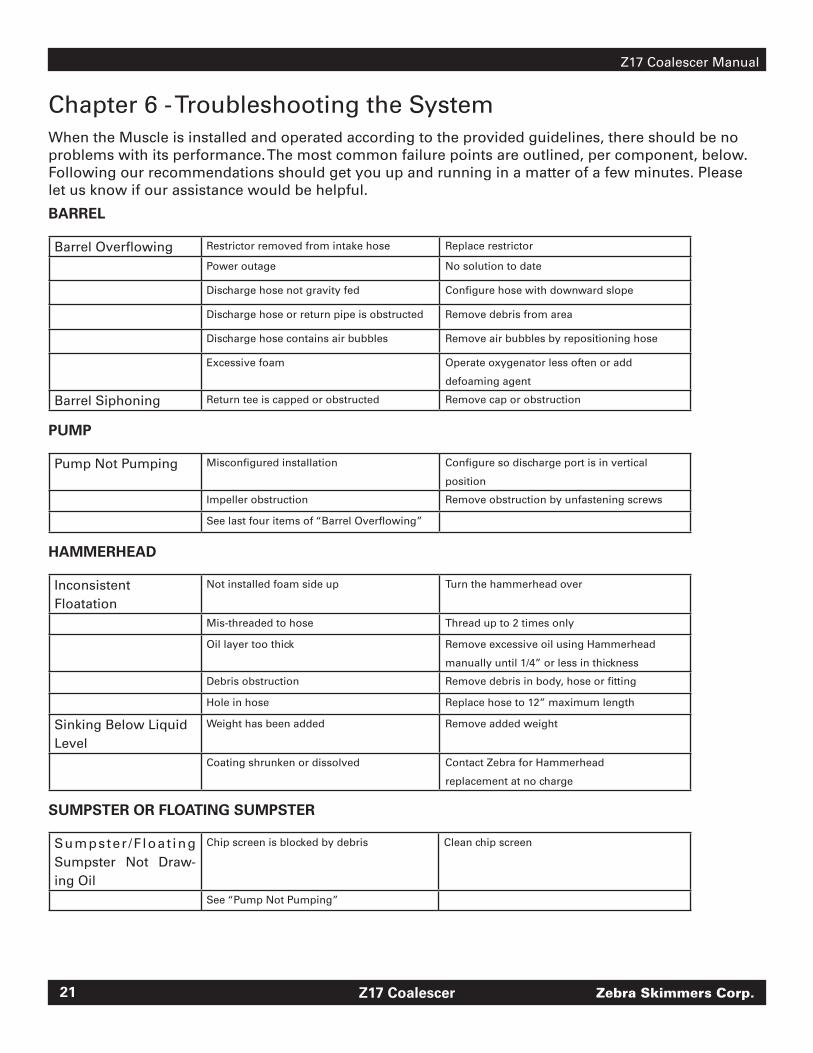
Chapter 6 - Troubleshooting the SystemWhen the Muscle is installed and operated according to the provided guidelines, there should be no problems with its performance. The most common failure points are outlined, per component, below. Following our recommendations should get you up and running in a matter of a few minutes. Please let us know if our assistance would be helpful.
BARREL
Barrel Overflowing Restrictor removed from intake hose Replace restrictor
Power outage No solution to date
Discharge hose not gravity fed Configure hose with downward slope
Discharge hose or return pipe is obstructed Remove debris from area
Discharge hose contains air bubbles Remove air bubbles by repositioning hose
Excessive foam Operate oxygenator less often or add
defoaming agent
Barrel Siphoning Return tee is capped or obstructed Remove cap or obstruction
PUMP
Pump Not Pumping Misconfigured installation Configure so discharge port is in vertical
position
Impeller obstruction Remove obstruction by unfastening screws
See last four items of “Barrel Overflowing”
HAMMERHEAD
Inconsistent Floatation
Not installed foam side up Turn the hammerhead over
Mis-threaded to hose Thread up to 2 times only
Oil layer too thick Remove excessive oil using Hammerhead
manually until 1/4” or less in thickness
Debris obstruction Remove debris in body, hose or fitting
Hole in hose Replace hose to 12” maximum length
Sinking Below Liquid Level
Weight has been added Remove added weight
Coating shrunken or dissolved Contact Zebra for Hammerhead
replacement at no charge
SUMPSTER OR FLOATING SUMPSTER
Sumpster /F loat ing Sumpster Not Draw-ing Oil
Chip screen is blocked by debris Clean chip screen
See “Pump Not Pumping”

Z17 Coalescer Manual
www.ZebraSkimmers.com 22
A Brand new coolantB Coolant has lost antirust inhibitorsC This is the level of performance required in a shop that works
with very high tolerances and finishes. This can also be a pro-duction shop where tool life and performance is critical.
D Coolant lost most anti-emulsifiers and takes longer than 15 minutes to reject tramp oils.
E This is the level of performance required by an above average machine shop, working in both rough and high tolerance spec-ifications.
F This level of coolant performance is acceptable to a rough and ready shop working with low-tolerance parts and little attention to finish. Tool life is not a consideration as setups are frequent. This is not a production shop.
G Coolant is “dead.”
NOTES: Coolant Performance Level (the Y portion of this graph) is the
same as Coolant Effectiveness and can be measured in different ways.
The most practical is ease of machining, tool life, and quality of fin-
ish for the finished part. A more quantitative approach can detail how
many minutes it takes for the tramp oils to be rejected and float / co-
alesce on the surface after a specific amount of agitation. The various
levels (A, B, C...) on the graph are used to denote general levels only,
and do not indicate any specific coolant or performance level.
Disclaimer: These are examples only, based on our cumulative experience with thousands of customers and hundreds of types of coolant. However, it is likely that your coolant performance curve will vary for many reasons. See your coolant supplier for details.
AppendicesAppendix A: Coolant Performance Curves
With and Without Proper Maintenance
A machine shop using flood coolant machines only eight hours per day and five days a week will find the first curve typical - while a shop using the flood coolant machines 24/7 will find the second curve more typical - also, the times are relative - in fact, abused coolant could ‘die’ (stage ‘G’) in several weeks if it is abused and not properly main-tained.
23 Zebra Skimmers Corp.Z17 Coalescer
Z17 Coalescer Manual
Appendix B: Third Party Pump Information
Little Giant-Small Submersible Encapsulated Pump Model 1-EA-42* Installation * Maintenance * Oper-ation * Repair Parts
These instructions will provide you with information required to safely own and operate the Little Giant Encapsulated 1-EA Se-ries Pump. The pump you have purchased with your F2b and F3 Zebra Muscle & Sumpster Unit is a submersible epoxy encapsu-lated pump (some models are for in-line use) with outer case constructed of durable die cast aluminum and polyester. The inside case is filled with a special heat transfer epoxy.
These instructions cover the standard models of the 1-EA Series. Always order replacement parts for the specific Catalog Num-ber of your pump. If the catalog number of your pump is not listed in the replacement parts section, then caution should be exercised when ordering replacement parts.
Little Giant pumps are carefully inspected, tested, and packaged to insure safe operation. When you receive your pump, examine it carefully to determine that there are no broken or damaged parts that may have occurred in shipment. If damage has occurred, make notation and notify Zebra Skimmers as soon as possible. We will assist you in the replacement or repair of your pump.
READ INSTRUCTIONS CAREFULLY BEFORE ATTEMPTING TO INSTALL, OPERATE OR SERVICE THE LITTLE GIANT PUMP. KNOW THE PUMP APPLICATIONS, LIMITATIONS, AND POTENTIAL HAZARDS. PROTECT YOURSELF AND OTHERS BY OBSERVING ALL SAFETY INFORMATION. FAILURE TO COMPLY WITH INSTRUCTIONS COULD RESULT IN PERSONAL INJURY AND/OR PROPER-
TY DAMAGE! RETAIN INSTRUCTIONS FOR FUTURE REFERENCE.
SAFETY GUIDELINES1. DO NOT USE TO PUMP FLAMMABLE OR EXPLOSIVE FLUIDS SUCH
AS GASOLINE, FUEL OIL, KEROSENE, ETC. DO NOT USE IN EXPLO-
SIVE ATMOSPHERES. PUMP SHOULD ONLY BE USED WITH LIQUIDS
COMPATIBLE WITH PUMP COMPONENT MATERIALS.
2. DO NOT HANDLE PUMP WITH WET HANDS OR WHEN STANDING ON
WET OR DAMP SURFACE, OR IN WATER.
3. DO NOT PULL THE PUMP OUT OF WATER BY THE POWER CORD
WHEN THE PUMP IS OPERATING OR CONNECTED TO THE POWER
SOURCE.
4. THIS PUMP IS SUPPLIED WITH A GROUNDING CONDUCTOR AND/
OR GROUNDING TYPE ATTACHMENT PLUG. TO REDUCE THE RISK OF
ELECTRIC SHOCK, BE CERTAIN THAT IT IS CONNECTED TO A PROP-
ERLY GROUNDED-GROUNDING TYPE RECEPTACLE.
5. THE NATIONAL ELECTRIC CODE REQUIRES A GROUND FAULT CIR-
CUIT INTERRUPTER (GFCI0 BE INSTALLED IN THE BRANCH CIRCUIT
SUPPLYING FOUNTAIN EQUIPMENT, POOLS, ETC.
6. IN ANY INSTALLATION WHERE PROPERTY DAMAGE AND/OR PER-
SONAL INJURY MIGHT RESULT FROM AN INOPERATIVE OR LEAK-
ING PUMP DUE TO POWER OUTAGES, DISCHARGE LINE BLOCKAGE,
OR ANY OTHER REASON, A BACKUP SYSTEM(S) AND/OR ALARM
SHOULD BE USED.
7. SUPPORT YOUR PUMP AND PIPING WHEN ASSEMBLING AND WHEN
INSTALLED. FAILURE TO DO SO MAY CAUSE PIPING TO BREAK, PUMP
TO FAIL, MOTOR BEARING FAILURES, ETC.
ELECTRICAL CONNECTIONS1. Check the pump label for proper voltage required. Do not
connect to voltage other than that shown.
2. If pump is supplied with a 3-prong electrical plug, the third
plug is to ground the pump to prevent possible electrical
shock hazard. DO NOT REMOVE the third plug from the
cord. If the plug is cut or the cord is shortened, then this
action will void the warranty.
3. If the cord is equipped with stripped lead wires, such as on
230v models, be sure that the lead wires are connected to
a power source supply correctly. The green/yellow wire is
the ground, the other two are live.
Little Giant-Tecumseh Products Company3810 N. Tulsa Street
Oklahoma City, OK 73112
Elite-Rolf C. Hogan (USA) Corp.50 Hampton Road
Mansfield, MA 02048

Z17 Coalescer Manual
www.ZebraSkimmers.com 24
OPERATION
1. The 1-EA style pumps must be run submerged. The pump
should be placed with the screen as a base or with cord up.
The volute should always be flooded or under water. If the
surface is sandy or muddy a separate hard surface such as
a brick should (provided) be under the pump to help prevent
clogging of the screen.
2. The 1-EA 42 style pumps may be operated submerged or
inline. They may be positioned at any attitude, but preferably
with the volute located down or to the side.
3. The weight of the pumps must be supported adequately.
DO NOT support the pumps by the discharge connection
alone. Pumps may be supported by using the two mounting
holes in the back of the pump. The holes are designed for #8
self-tapping screws. Hole depth is .37 - DO NOT exceed the
hole depth.
4. Do not attempt to restrict the intake side of these pumps.
Restricting the intake may cause damage to the seal and may
starve the pump. If you require reduced flow rates, then place
a valve on the discharge side of the pump or if flexible vinyl
tubing is used, a clamp can be used to restrict the flow.
5. Do not let the unit operate dry. It is designed to be cooled by
pumping fluid. You may damage the seal and the motor may
fail if the pump is allowed to run dry.
6. If the unit is going to be idle for a period of time, follow the
cleaning instructions outlined in the next section. Do not let
the unit freeze in wintertime. This may cause cracking or dis-
tortion that may destroy the unit.
SERVICE INSTRUCTIONS
MAKE CERTAIN THAT THE UNIT IS DISCONNECTED FROM THE POW-ER SOURCE BEFORE ATTEMPTING TO SERVICE OR REMOVE ANY COMPONENT!
1. This unit is permanently lubricated. Oiling is not required. DO NOT, in any case, open the sealed portion of the unit or remove the housing screws.2. Periodic cleaning of the pump parts will prolong the LIFE and EF-FICIENCY of the pump. Refer to the drawing below for the assembly and disassembly of the pumping head.3. First remove the screen from the pump. Then remove the 3 screws as indicated by the arrows. (Do NOT remove other screws which may be exposed).4. Lightly scrape and clean any corrosion or debris which may clog the impeller. Use a brush and penetrating oil and lightly scrape to remove encrusted material.5. Turn the impeller by hand to make sure it turns freely. Set pump down so you are not touching pump and impeller is not touching anything. Plug the unit into GFCI circuit for 10 seconds to see if the impeller turns; (a) if it is rotating and GFCI did not trip, unplug unit and install parts in reverse order in which they were removed. (b) If it does not rotate, if pump is tripping circuit breakers, or not operating properly after cleaning, return to Little Giant or it’s authorized (Zebra Skimmers) service center. DO NOT attempt repairs yourself!6. Be certain power cord is in good condition and contains no nicks or cuts.
Limited WarrantyLITTLE GIANT WARRANTY STATEMENTYour Little Giant product is guaranteed to be in perfect condition when it leaves our factory. It is warranted against defective materials and workmanship for a period of 12 months (90 days warranty on Models 1-AA-OM, GKPK-SC, PP-1, PPS-12, PP-230 and Cooler King) from date of purchase by the user. No warranty on brush wear in Model 35-OM and impeller or cam in Models PP-1, PP-12, PP-230. Any product that should fail for either of the above two reasons and is still within the warranty period, will be repaired or replaced if returned prepaid to our factory. All defective products returned under our warranty will be fully inspected to determine “CAUSE OF FAILURE” before any warranty is approved. Little Giant will honor the warranty within the warranty time period specified on satisfactory written proof of purchase.DISCLAIMER: Any oral statements about the product made by the seller, the manufacturer, the representatives or any other parties, do not constitute warranties, shall not be relied upon by the user, and are not part of the contract for sale. Seller’s and manufacturer’s only obliga-tion, and buyer’s only remedy, shall be the replacement and/or repair by the manufacturer of the product as described above. Neither seller nor the manufacturer shall be liable for any injury, loss or damage, direct, incidental or consequential (including, but not limited to, incidental or consequential damages for lost profits, lost sales, injury to person or property, or any other incidental or consequential loss), arising out of the use or the ability to use the product, and the user agrees that no other remedy shall be available to it. Before using, the user shall determine the suitability of the product for his/her intendeduse, and user assumes all risk and liability whatsoever in connection therewith. THE WAR-RANTY AND REMEDY DESCRIBED IN THIS LIMITED WARRANTY IS AN EXCLUSIVE WARRAN-TY AND REMEDY AND IS IN LIEU OF ANY OTHER WARRANTY OR REMEDY, EXPRESSED OR IMPLIED, WHICH OTHER WARRANTIES AND REMEDIES ARE HEREBY EXPRESSLY EXCLUD-ED, INCLUDING , BUT NOT LIMITED TO ANY IMPLIED WARRANTY OF MERCHANTABILITY OR FITNESS FOR A PARTICULAR PURPOSE. Some states do not allow the exclusion or lim-itation of incidental or consequential damages, so the above limitation or exclusion may not apply to you. This warranty gives you specific legal rights, and you may also have other rights which vary from state to state.Warranty will be VOID if any of the following conditions are found:1. Sealed motor housing opened.2. Product connected to voltage other than indicated on name plate.3. Cord cut off to a length less than three feet.4. Pump allowed to operate dry (fluid supply cut off).5. Pump used to circulate anything other than fresh water, light oils, or other mild liquids at approximately room temperature.6. Product abuse by customer.The National Electric Code requires a Ground Fault Circuit Interrupter (GFCI) be installed in the branch circuit supplying fountain equipment rated above 15 volts. Little Giant Pump Com-pany offers a variety of FGCI’s and recommends each pump be used with a GFCI.

25 Zebra Skimmers Corp.Z17 Coalescer
Z17 Coalescer Manual
Notes:

Z17 Coalescer Manual
www.ZebraSkimmers.com 26
Notes: