Embed Size (px)
Citation preview

Discrete Layer Jamming for Safe Co-Robots
Yitong Zhou, Leon M. Headings, and Marcelo J. Dapino
Abstract— High injury severity occurs when a stiff robot armhits an operator. Introducing compliance into robot systemsreduces the impact and enables safe interaction, but at theexpense of positioning performance and payload capacity. Thispaper presents a tunable stiffness mechanism for safe human-robot interaction based on discrete layer jamming. The pro-posed design of a discrete layer jamming mechanism is a robotlink made of multiple thin layers of ABS and multiple clamps.By applying high clamping pressure to the laminates, thelink behaves like a rigid link; reducing the clamping pressuresoftens the link which yields safer human-robot interaction.Compared to conventional pneumatic layer jamming, discretelayer jamming allows for simplicity of installation with dynamicactuators, faster control, greater portability since no air supplyis needed, and no sealing issues. To validate the concept, thispaper investigates a discrete layer jamming beam made of tenABS laminates and two aluminum clamps that cover 10% ofthe surface of the beam. Stiffness tests have been performed,showing that around 17 times bending stiffness change isachieved by increasing the clamping pressure of two clampsfrom 0 to 1 MPa.
I. INTRODUCTION
Collaborative robots (co-robots) work closely with humanoperators in a variety of applications such as exoskele-tons for human strength amplification [1], wearable hapticdevices [2], rehabilitation [3], [4], and flexible productionlines [5]. Compared to conventional robots which are usuallyconfined in cages and fences to ensure safety, co-robots areexpected to be intrinsically safe such that humans interactingwith them do not suffer injury.
In recent times, introducing controllable compliance intorobotic systems has been proposed to fulfill safety require-ments. A number of studies have shown that variable stiffnesshelps to achieve high performance safely. There are tworepresentative mechanisms for varying stiffness: variablestiffness joints (VSJ) and variable stiffness links (VSL). Asthe first solution to be investigated, a large number of VSJstudies have been conducted [6]–[10]. The main researchactivities have been focusing on the safe brachistochroneproblem, which is an optimal control problem of minimizingthe time needed to move a mechanical load from oneposition to another under certain safety constraints. Headinjury criterion (HIC) [11] has been widely used as a headinjury indicator as well as a safety constraint in the roboticscommunity [7], [9], [12].
Recent research has indicated an increasing interest invariable stiffness links. Various approaches have been in-
This research was supported by the National Science Foundation, GrantNo: CMMI-1637656.
The authors are with the Department of Mechanical and AerospaceEngineering, The Ohio State University, Columbus, OH 43210 USA (e-mail:[email protected]; [email protected]; [email protected]).
vestigated to achieve controllable stiffness. She et al. [13]proposed a variable stiffness parallel-guided link based oncontrolling the area moment of inertia of the cross sec-tional area of a robot arm. However, the stiffness ratioof 3.6 provides only a modest opportunity for improvingperformance while maintaining a safe HIC value. Stilli etal. [14] designed a controllable-stiffness robot link made ofan airtight chamber formed by a plastic mesh and siliconewall; stiffness is varied by controlling the air pressure insidethe chamber. However, the stiffness change capability isunclear because the stiffness at lower pressure states wasnot investigated.
Granular jamming using granular media has been investi-gated for robotic applications such as robotic spines [15] andgripping [16]. In another case, if a robotic link is composedof a volume of granular material, e.g. dry sand or coffee, itcan effectively transition between compliant states and load-bearing stiff states by applying a vacuum to achieve variablestiffness [17], [18]. However, it requires a substantial volumeto achieve sufficient stiffness which adds bulk to roboticmanipulators.
A layer jamming system makes use of friction generatedbetween flexible laminates by applying a jamming force totransition between soft and stiff states. A variety of methodshave been implemented to provide a jamming force. Henke etal. [19] proposed a variable stiffness beam that uses an arrayof shape memory alloy (SMA) wires wrapped around a stackof laminates. By changing the temperature generated by anelectrical current flowing through the SMA wires, the wirescan contract or elongate, which changes the compressionforce around the layers, hence varying stiffness. However,this method is limited by the strength and speed of theSMA wires, and high SMA temperature on the outer surfacemay present a hazard. Tabata et al. [20] utilized electrostaticattractive forces generated by applying high voltage to flex-ible polyamide thin films with patterned nickel electrodesto change stiffness. However, high voltages used (from 150V to 750 V) could be dangerous and the stiffness changeis insufficient (4 times). A common approach, which uses avacuum to generate the jamming force, has been investigatedfor a variety of applications including continuum robots [21],user interfaces for human-computer interaction [22], andminimally invasive surgery [23]. However, it requires anexternal vacuum source which adds complexity, bulk, andweight to the layer jamming system. Furthermore, the thinmembranes used to contain the laminates are susceptible todamage from contact with rough edges.
In this paper, we propose a novel concept to changeeffective bending stiffness termed “discrete layer jamming.”

Our proposed design incorporates variable pressure clampsat discrete locations along a multilayered flexible beam. Thestiffness of the multilayered beam can be varied by changingthe clamping pressure. For proof of concept, a ten-layeredABS beam with two aluminum mechanical clamps has beendesigned and tested for a range of clamping pressures.The article is organized as follows: the design purpose andconcepts are presented in Section II. Section III shows thediscrete layer jamming design, and experiments to evaluatethe bending stiffness. Section IV provides a summary of thestudy and future work.
II. DESIGN PURPOSE AND CONCEPTS
A. Safety Criterion
A typical free impact between a single robot arm and anoperator is shown in Fig. 1(a). The robot arm is composedof an end effector with a load at one end and a link thatis connected to a joint at the other end. The robot link hasa length L and a mass mrob. The end load is mload. Theoperator’s head with a mass denoted as moper is hit by thelink at a distance r from the joint with an angular velocityω. The velocity of the robot link at the impact location ris calculated as v = ωr. The effective mass of the robot ismeff , which is obtained by equating the kinetic energy of themass meff and that of the original flexible vibrating beam,as shown in [24]. The effective bending stiffness of the linkand the covering material of both the operator’s head and therobot is keff . A mass-spring-mass impact model, shown inFig. 1(b), was proposed by Bicchi et al. [7]. In their model,robot rotor and link are both considered as rigid, and theonly compliance during impact is from the covering material.Hence, the HIC formula shown in Equation (1) of [7] isexpressed as a function of robot covering material stiffness,robot inertia, and operator inertia. She et al. [12] modifiedthe HIC equation for compliant link robots, replacing thecovering material stiffness in [7] with an effective stiffnesswhich is a resulting term of joint stiffness, link stiffness, androbot covering material stiffness. For a short impact periodof T , the HIC is expressed as follows [7]:
(a) (b)
Fig. 1: (a) Human robot collision. (b) Mass-spring-mass model.
HIC = 1.016Tk0.75eff
m−0.75oper m1.75
eff
(meff +moper)1.75v2.5, (1)
which shows that HIC is affected by time duration of theimpact, impact velocity, effective stiffness, effective mass,and operator’s head mass. An HIC value of 100 may beconsidered as an appropriate threshold for human robotinteraction [7]. To simplify and consider only the effect of acompliant link, joint stiffness and covering material stiffnesscan be reasonably assumed infinitely large, and the effectivestiffness is simply the link stiffness keff = 3Y I/r3, whereY is the elastic modulus and I is the area moment of inertiaof the link [12]. Substituting the link effective stiffness andv = ωr into (1) yields:
HIC(r) = 1.016T (3Y I)0.75m−0.75
oper m1.75eff
(meff +moper)1.75ω2.5r0.25,
(2)which shows that HIC increases with Y I , angular velocity,impact length, and impact system masses. Fixing otherparameters, when r = L, HIC is found to be maximum.Substituting r = L into (2), HIC at L can be calculated as:
HIC(L) = 1.016T
(3Y I
L3
)0.75 m−0.75oper m1.75
eff
(meff +moper)1.75(ωL)2.5.
(3)Here, 3Y I/L3 is the bending stiffness of an Euler-
Bernoulli beam for small deflections. It shows that the valueof HIC increases with bending stiffness to the power of 0.75.Reducing bending stiffness helps to reduce the HIC value,hence improving safety. For instance, fixing other parametersand decreasing the bending stiffness by 10 times, the HICvalue can be reduced by 5.6 times.
B. Layer Jamming Concept
The layer jamming concept is illustrated in Fig. 2, wherethe main structure is a multilayered beam. The most compli-ant state is shown in Fig. 2(a), where no compression force isapplied and each layer bends almost independently when anend load is applied. A stiff state with external compressionforce applied to the outer surface of the beam is displayedin Fig. 2(b).
The compression force increases the friction couplingbetween the layers during bending to resist sliding andthus increases bending stiffness. The theoretical maximumstiffness change that a layer jamming system can achieveis n2, where n represents the number of layers [19], [25].Therefore, a 10-layered beam at its stiffest (fully jammed)state can theoretically be 100 times stiffer than its most com-pliant (unjammed) state. However, pneumatic layer jammingis limited by the capabilities of the pneumatic source and theactuation speed can be too slow for some types of roboticcontrol.
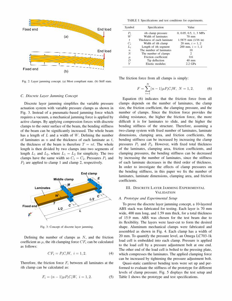
Fig. 2: Layer jamming concept. (a) Most compliant state. (b) Stiff state.
C. Discrete Layer Jamming Concept
Discrete layer jamming simplifies the variable pressureactuation system with variable pressure clamps as shown inFig. 3. Instead of a pneumatic-based jamming force whichrequires a vacuum, a mechanical jamming force is applied byactive clamps. By applying compression forces with discreteclamps to the outer surface of the beam, the bending stiffnessof the beam can be significantly increased. The whole beamhas a length of L and a width of W . Defining the numberof laminates as n and the thickness of each laminate as t,the thickness of the beam is therefore T = nt. The wholelength is then divided by two clamps into two segments oflength L1 and L2, where L1 = L2 for simplicity. The twoclamps have the same width so C1 = C2. Pressures P1 andP2 are applied to clamp 1 and clamp 2, respectively.
Middle clamp
Laminates
L
End clamp
L/2C
L/2CW
M
E
Fixed endT
Fig. 3: Concept of discrete layer jamming.
Defining the number of clamps as N , and the frictioncoefficient as µ, the ith clamping force CFi can be calculatedas follows:
CFi = PiCiW, i = 1, 2. (4)
Therefore, the friction force Fi between all laminates at theith clamp can be calculated as:
Fi = (n− 1)µPiCiW, i = 1, 2. (5)
TABLE I: Specifications and test conditions for experiments.
Symbol Specification Value
Pi ith clamp pressure 0, 0.05, 0.5, 1, 3 MPaW Width of laminates 70 mmt Thickness of each laminate 1.5875 mm (1/16 in)Ci Width of ith clamp 20 mm, i = 1, 2Li Length of ith segment 200 mm, i = 1, 2n The number of laminates 10N The number of clamps 2µ Friction coefficient 0.6D Tip deflection 40 mmY Elastic modulus 2.2 GPa
The friction force from all clamps is simply:
F =N∑i=1
(n− 1)µPiCiW, N = 1, 2. (6)
Equation (6) indicates that the friction force from allclamps depends on the number of laminates, the clampsize, the friction coefficient, the clamping pressure, and thenumber of clamps. Since the friction force provides thesliding resistance, the higher the friction force, the moredifficult it is for laminates to slide, and the higher thebending stiffness of the structure. Therefore, assuming atwo-clamp system with fixed number of laminates, laminatedimensions, clamping area, and friction coefficients, thebending stiffness can be increased by increasing the clamppressures P1 and P2. However, with fixed total thicknessof the laminates, clamping area, friction coefficients, andclamping pressures, the bending stiffness can be decreasedby increasing the number of laminates, since the stiffnessof each laminate decreases in the third order of thickness.In order to investigate the effects of clamp pressures onthe bending stiffness, in this paper we fix the number oflaminates, laminate dimensions, clamping area, and frictioncoefficients.
III. DISCRETE LAYER JAMMING EXPERIMENTALVALIDATION
A. Prototype and Experimental Setup
To prove the discrete layer jamming concept, a 10-layeredABS stack was fabricated for testing. Each layer is 70 mmwide, 400 mm long, and 1.59 mm thick, for a total thicknessof 15.9 mm. ABS was chosen for the test beam due toits flexibility. The layers were laser-cut to form the desiredshape. Aluminum mechanical clamps were fabricated andassembled as shown in Fig. 4. Each clamp has a width of20 mm. To quantify the pressure level, an Omega LC703-1kload cell is embedded into each clamp. Pressure is appliedto the load cell by a pressure adjustment bolt at one end.The other end of the load cell is bolted to the pressing plate,which compresses the laminates. The applied clamping forcecan be increased by tightening the pressure adjustment bolt.
Quasi-static cantilever bending tests were set up and per-formed to evaluate the stiffness of the prototype for differentlevels of clamp pressure. Fig. 5 displays the test setup andTable I shows the prototype and test specifications.

LaminatesFrame
Load cell
Pressure adjustment bolt
Pressing plate
Pressing block
(a) (b)
Fig. 4: Clamp design. (a) Solid rendering. (b) Experimental unit.
Fig. 5: Cantilever bending test setup.
The prototype was clamped at one end and deflectedmanually at the other end by a Mark-10 ES30 load frame.The first and second clamps were placed 180 mm and 380mm from the fixed end, respectively, so that the beam lengthwas equally partitioned into two segments. The tip loadand tip deflection were measured by a Mark-10 ME-200force gauge and a Mark-10 ESM001 digital travel display,respectively. To indicate the clamp location more clearly, thefirst and second clamp are named as the middle and endclamp, respectively.
B. Test Procedures
Twenty-five pressure states were set up and tested withpressure combinations of 0, 0.05, 0.5, 1, and 3 MPa appliedto the middle and end clamps. Zero pressure throughout thispaper means no pressure and no clamps, indicating the beamis free of constraints in clamped regions at the zero pressurestate.
For each pressure state, one cantilever bending test wasperformed for three loading and unloading cycles. The tipwas deflected to 40 mm for each loading cycle. For abbre-viated notation of different pressure states, the pressure formiddle and end clamps are denoted as ”M E ”, where “M ”denotes the middle clamp pressure and “E ” denotes the endclamp pressure. The pressure unit throughout this paper isMPa. For example, M0E3 represents a pressure state with
middle clamp pressure of 0 (no clamps and pressure) andend clamp pressure of 3 MPa. M0E0 represents the clampand pressure free state.
C. Experimental Results and Discussion
The force-displacement curves are shown in Fig. 6 for M0,M0.05, M0.5, M1, and M3 cases with end clamp pressuresof E0, E0.05, E0.5, E1, and E3. All figures except theM0 series exhibit similar slopes at very small deflections,which indicates that the stiffness is independent of theclamp pressure. This independence is due to the fact thatslipping (laminates sliding relative to each other) occurs onlywhen the shear force between individual laminates exceedsthe limit for static friction. Below this level, the laminateseffectively stick to each other. Once the laminates begin toslip, the curves become nonlinear. Fig. 6 (c), Fig. 6 (d),and Fig. 6 (e) look similar, which indicates that increasingmiddle clamp pressure above 0.5 MPa helps little to increasestiffness. The E0.5, E1, and E3 curves almost overlap witheach other for every middle clamp pressure for the first partof the loading curve for the first cycle, thus providing similarstiffnesses. The M0E0.05 curve in Fig. 6(b) exhibits a wavybehavior at large deflection, and M1E0.05 and M3E0.05curves both exhibit a drop, which are due to slipping betweenthe laminates. Hysteresis was observed at all pressure states,but lower pressure states exhibit higher hysteresis. Hysteresisis likely a result of internal friction during sliding betweenthe laminates; because there is less sliding at higher pressurestates, there is less hysteresis.
To compare the overall stiffness of different pressurestates, stiffness was calculated by fitting the slope of the first20 mm of each force-displacement curve. Fig. 7 illustratesthe stiffness versus end clamp pressure for different middleclamp pressures. While the overall trends of the curves showthat higher end clamp pressures yield higher stiffnesses, thestiffness increases little when increasing end clamp pressurefrom 0.5 MPa to 3 MPa as we already observed in theforce-displacement curves. Similarly, stiffness increases withmiddle clamp pressure and differs little at higher middleclamp pressures, i.e., M0.5, M1, and M3. The M0.05 curveshows a downward trend. The reason is that 0.05 MPacorresponds to a small load relative to the 3.17 MPa rangeof the load cell. Both clamps were adjusted between tests,which resulted in some variability in the applied pressures,especially for small pressures, i.e., the M0.05 series.
TABLE II: Stiffness for different middle and end clamp pressure combina-tions from experiments.
Stiffness (N/mm)Middle clamp pressure (MPa)
0 0.05 0.5 1 3
End clamp pressure (MPa)
0 0.024 0.12 0.17 0.17 0.170.05 0.10 0.19 0.35 0.34 0.360.5 0.11 0.22 0.39 0.40 0.401 0.12 0.22 0.40 0.40 0.413 0.11 0.19 0.39 0.39 0.40

(a) (b) (c) (d) (e)
Fig. 6: Force-displacement curves of different pressure states. (a) M0 series tests. (b) M0.05 series tests. (c) M0.5 series tests. (d) M1 series tests. (e) M3series tests.
Fig. 7: Stiffness vs. end clamp pressure from experiments.
Stiffness ratio is defined as kp/kmin, where kp is thestiffness of a certain pressure state, and kmin is the minimumstiffness, corresponding to the case of no clamps or pressure.The maximum stiffness ratio is defined as Kr = kmax/kmin,where kmax is the maximum stiffness over the range ofpressures investigated. Table II and Table III list the stiff-nesses and stiffness ratios for all 25 pressure states. Herekmax was found to be 0.41 N/mm at the M3E1 pressurestate and kmin 0.024 N/mm at the no clamp or pressure state(M0E0). The maximum stiffness ratio Kr is 17, which meansthat clamping two discrete clamps can provide a 17 timesincrease in bending stiffness. In addition, when comparingthe stiffness on the opposite sides of the diagonal connectingM0E0 and M3E3 of Table II, e.g., M3E0.05 and M0.05E3,which are 0.36 N/mm and 0.19 N/mm respectively, it is
TABLE III: Stiffness ratio for different middle and end clamp pressurecombinations from experiments.
Stiffness ratioMiddle clamp pressure (MPa)
0 0.05 0.5 1 3
End clamp pressure (MPa)
0 1.0 5.1 7.1 7.0 7.20.05 4.2 7.9 15 14 150.5 4.6 9.3 16 17 171 4.9 9.2 17 17 173 4.8 8.2 16 17 17
observed that the upper right values are greater than thelower left values. Likewise, comparing the M0 column withthe E0 row indicates that the middle clamp is more effectiveat increasing stiffness than the end clamp.
IV. CONCLUSIONS
This paper presented the principle of discrete layer jam-ming for tunable stiffness robot links, along with detailsof the design concept, prototype, and experimental results.Detailed analysis of its stiffness properties and verificationof its performance based on experiments proved that beamstiffness increases with clamp pressure. The stiffness changeof the current discrete layer jamming structure can be as highas 17 times, which makes discrete layer jamming structurespromising for robotic applications.
Future work will focus on clamp actuator design andcontrol to maximize safety and performance. The use ofsmart materials such as piezoelectrics will be considered dueto their fast response. The design of automated clampingactuators will be an extension of the current work to betackled in subsequent papers. There are a number of op-tions ranging from conventional electrical actuators to shape

memory alloys. We will also investigate design parametersthat affect bending stiffness, such as the number of clampsand clamp location.
REFERENCES
[1] A. Chu, H. Kazerooni, and A. Zoss, “On the biomimetic designof the berkeley lower extremity exoskeleton (bleex),” in Roboticsand Automation, 2005. ICRA 2005. Proceedings of the 2005 IEEEInternational Conference on. Citeseer, 2005, pp. 4345–4352.
[2] A. Frisoli, F. Rocchi, S. Marcheschi, A. Dettori, F. Salsedo, andM. Bergamasco, “A new force-feedback arm exoskeleton for hapticinteraction in virtual environments,” in Eurohaptics Conference, 2005and Symposium on Haptic Interfaces for Virtual Environment andTeleoperator Systems, 2005. World Haptics 2005. First Joint. IEEE,2005, pp. 195–201.
[3] S. Roderick and C. Carignan, “Designing safety-critical rehabilitationrobots,” in Rehabilitation Robotics. InTech, 2007.
[4] E. T. Wolbrecht, V. Chan, D. J. Reinkensmeyer, and J. E. Bobrow,“Optimizing compliant, model-based robotic assistance to promoteneurorehabilitation,” IEEE Transactions on Neural Systems and Re-habilitation Engineering, vol. 16, no. 3, pp. 286–297, 2008.
[5] J. Kruger, T. K. Lien, and A. Verl, “Cooperation of human andmachines in assembly lines,” CIRP Annals-Manufacturing Technology,vol. 58, no. 2, pp. 628–646, 2009.
[6] A. Bicchi, G. Tonietti, and E. Piaggio, “Design, realization and controlof soft robot arms for intrinsically safe interaction with humans,” inProc. IARP/RAS Workshop on Technical Challenges for DependableRobots in Human Environments, 2002, pp. 79–87.
[7] A. Bicchi and G. Tonietti, “Fast and” soft-arm” tactics [robot armdesign],” IEEE Robotics & Automation Magazine, vol. 11, no. 2, pp.22–33, 2004.
[8] G. Tonietti, R. Schiavi, and A. Bicchi, “Optimal mechanical/controldesign for safe and fast robotics,” in Experimental Robotics IX.Springer, 2006, pp. 311–320.
[9] S. Haddadin, A. Albu-Schaffer, O. Eiberger, and G. Hirzinger, “Newinsights concerning intrinsic joint elasticity for safety,” in IntelligentRobots and Systems (IROS), 2010 IEEE/RSJ International Conferenceon. IEEE, 2010, pp. 2181–2187.
[10] L. Chen, M. Garabini, M. Laffranchi, N. Kashiri, N. G. Tsagarakis,A. Bicchi, and D. G. Caldwell, “Optimal control for maximizing veloc-ity of the compact™ compliant actuator,” in Robotics and Automation(ICRA), 2013 IEEE International Conference on. IEEE, 2013, pp.516–522.
[11] J. A. Newman, “Head injury criteria in automotive crash testing,” SAETechnical Paper, Tech. Rep., 1980.
[12] Y. She, H.-J. Su, D. Meng, S. Song, and J. Wang, “Design andmodeling of a compliant link for inherently safe corobots,” Journalof Mechanisms and Robotics, vol. 10, no. 1, p. 011001, 2018.
[13] Y. She, H.-J. Su, C. Lai, and D. Meng, “Design and prototype of atunable stiffness arm for safe human-robot interaction,” in ASME 2016International Design Engineering Technical Conferences and Comput-ers and Information in Engineering Conference. American Societyof Mechanical Engineers, 2016, pp. V05BT07A063–V05BT07A063.
[14] A. Stilli, L. Grattarola, H. Feldmann, H. A. Wurdemann, and K. Al-thoefer, “Variable stiffness link (vsl): Toward inherently safe roboticmanipulators,” in Robotics and Automation (ICRA), 2017 IEEE Inter-national Conference on. IEEE, 2017, pp. 4971–4976.
[15] Y. Wei, Y. Chen, Y. Yang, and Y. Li, “A soft robotic spine withtunable stiffness based on integrated ball joint and particle jamming,”Mechatronics, vol. 33, pp. 84–92, 2016.
[16] J. R. Amend, E. Brown, N. Rodenberg, H. M. Jaeger, and H. Lipson,“A positive pressure universal gripper based on the jamming ofgranular material,” IEEE Transactions on Robotics, vol. 28, no. 2,pp. 341–350, 2012.
[17] N. G. Cheng, M. B. Lobovsky, S. J. Keating, A. M. Setapen, K. I.Gero, A. E. Hosoi, and K. D. Iagnemma, “Design and analysis of arobust, low-cost, highly articulated manipulator enabled by jammingof granular media,” in Robotics and Automation (ICRA), 2012 IEEEInternational Conference on. IEEE, 2012, pp. 4328–4333.
[18] T. Ranzani, M. Cianchetti, G. Gerboni, I. De Falco, and A. Menciassi,“A soft modular manipulator for minimally invasive surgery: designand characterization of a single module,” IEEE Transactions onRobotics, vol. 32, no. 1, pp. 187–200, 2016.
[19] M. Henke and G. Gerlach, “On a high-potential variable-stiffnessdevice,” Microsystem technologies, vol. 20, no. 4-5, pp. 599–606,2014.
[20] O. Tabata, S. Konishi, P. Cusin, Y. Ito, F. Kawai, S. Hirai, andS. Kawamura, “Micro fabricated tunable bending stiffness devices,”Sensors and Actuators A: Physical, vol. 89, no. 1-2, pp. 119–123,2001.
[21] J. L. C. Santiago, I. D. Walker, and I. S. Godage, “Continuum robotsfor space applications based on layer-jamming scales with stiffeningcapability,” in Aerospace Conference, 2015 IEEE. IEEE, 2015, pp.1–13.
[22] S. Follmer, D. Leithinger, A. Olwal, N. Cheng, and H. Ishii, “Jam-ming user interfaces: programmable particle stiffness and sensing formalleable and shape-changing devices,” in Proceedings of the 25thannual ACM symposium on User interface software and technology.ACM, 2012, pp. 519–528.
[23] Y.-J. Kim, S. Cheng, S. Kim, and K. Iagnemma, “A novel layerjamming mechanism with tunable stiffness capability for minimallyinvasive surgery,” IEEE Transactions on Robotics, vol. 29, no. 4, pp.1031–1042, 2013.
[24] G. Zhu, S. S. Ge, and T. H. Lee, “Simulation studies of tip trackingcontrol of a single-link flexible robot based on a lumped model,”Robotica, vol. 17, no. 1, pp. 71–78, 1999.
[25] S. Kawamura, T. Yamamoto, D. Ishida, T. Ogata, Y. Nakayama,O. Tabata, and S. Sugiyama, “Development of passive elements withvariable mechanical impedance for wearable robots,” in Roboticsand Automation, 2002. Proceedings. ICRA’02. IEEE InternationalConference on, vol. 1. IEEE, 2002, pp. 248–253.