Embed Size (px)
Citation preview

Copyright © 2014 YEALINK NETWORK TECHNOLOGY
Copyright © 2014 Yealink Network Technology CO., LTD. All rights reserved. No parts of this
publication may be reproduced or transmitted in any form or by any means, electronic or
mechanical, photocopying, recording, or otherwise, for any purpose, without the express written
permission of Yealink Network Technology CO., LTD. Under the law, reproducing includes
translating into another language or format.
When this publication is made available on media, Yealink Network Technology CO., LTD. gives
its consent to downloading and printing copies of the content provided in this file only for private
use but not for redistribution. No parts of this publication may be subject to alteration,
modification or commercial use. Yealink Network Technology CO., LTD. will not be liable for any
damages arising from use of an illegally modified or altered publication.
THE SPECIFICATIONS AND INFORMATION REGARDING THE PRODUCTS IN THIS GUIDE ARE
SUBJECT TO CHANGE WITHOUT NOTICE. ALL STATEMENTS, INFORMATION, AND
RECOMMENDATIONS IN THIS GUIDE ARE BELIEVED TO BE ACCURATE AND PRESENTED
WITHOUT WARRANTY OF ANY KIND, EXPRESS OR IMPLIED. USERS MUST TAKE FULL
RESPONSIBILITY FOR THEIR APPLICATION OF PRODUCTS.
YEALINK NETWORK TECHNOLOGY CO., LTD. MAKES NO WARRANTY OF ANY KIND WITH
REGARD TO THIS GUIDE, INCLUDING, BUT NOT LIMITED TO, THE IMPLIED WARRANTIES OF
MERCHANTABILITY AND FITNESS FOR A PARTICULAR PURPOSE. Yealink Network Technology
CO., LTD. shall not be liable for errors contained herein nor for incidental or consequential
damages in connection with the furnishing, performance, or use of this guide.
Hereby, Yealink Network Technology CO., LTD. declares that this phone is in conformity
with the essential requirements and other relevant provisions of the CE, FCC.
This device is marked with the CE mark in compliance with EC Directives 2006/95/EC and 2004/108/EC.
This device is compliant with Part 15 of the FCC Rules. Operation is subject to the following two conditions:
1. This device may not cause harmful interference, and
2. This device must accept any interference received, including interference that may cause undesired
operation.
Note: This device is tested and complies with the limits for a Class B digital device, pursuant to Part 15 of the
FCC Rules. These limits are designed to provide reasonable protection against harmful interference in a
residential installation. This equipment generates, uses, and can radiate radio frequency energy and, if not
installed and used in accordance with the instructions, may cause harmful interference to radio
communications. However, there is no guarantee that interference will not occur in a particular installation. If
this equipment does cause harmful interference to radio or television reception, which can be determined
by turning the equipment off and on, the user is encouraged to try to correct the interference by one or more
of the following measures:
1. Reorient or relocate the receiving antenna.
2. Increase the separation between the equipment and receiver.
3. Connect the equipment into an outlet on a circuit different from that to which the receiver is connected.
4. Consult the dealer or an experience radio/TV technician for help.
To avoid the potential effects on the environment and human health as a result of the
presence of hazardous substances in electrical and electronic equipment, end users of
electrical and electronic equipment should understand the meaning of the crossed-out
wheeled bin symbol. Do not dispose of WEEE as unsorted municipal waste and have to
collect such WEEE separately.
We are striving to improve our documentation quality and we appreciate your feedback. Email
your opinions and comments to [email protected].

Yealink IP phone firmware contains third-party software under the GNU General Public License (GPL).
Yealink uses software under the specific terms of the GPL. Please refer to the GPL for the exact terms and
conditions of the license.
The original GPL license, source code of components licensed under GPL and used in Yealink products can
be downloaded from Yealink web site:
http://www.yealink.com/GPLOpenSource.aspx?BaseInfoCateId=293&NewsCateId=293&CateId=293.
About This Guide
v
This guide is intended for administrators who need to properly configure, customize,
manage, and troubleshoot the IP phone system rather than end-users. It provides
details on the functionality and configuration of IP phones.
Many of the features described in this guide involve network settings, which could affect
the IP phone’s performance in the network. So an understanding of IP networking and a
prior knowledge of IP telephony concepts are necessary.
This guide covers SIP-T28P, SIP-T26P, SIP-T22P, SIP-T21P, SIP-T20P and SIP-T19P IP phones. The
following related documents are available:
Quick Installation Guides, which describe how to assemble IP phones.
Quick Reference Guides, which describe the most basic features available on IP
phones.
User Guides, which describe the basic and advanced features available on IP
phones.
Auto Provisioning Guide, which describes how to provision IP phones using the
configuration files.
<y0000000000xx>.cfg and <MAC>.cfg template configuration files.
IP Phones Deployment Guide for BroadSoft UC-One Environments, which describes
how to configure BroadSoft features on the BroadWorks web portal and IP phones.
For support or service, please contact your Yealink reseller or go to Yealink Technical
Support online: http://www.yealink.com/Support.aspx.
The information detailed in this guide is applicable to firmware version 72 or higher. The
firmware format is like x.x.x.x.rom. The second x from left must be greater than or equal
to 72 (e.g., the firmware version of SIP-T28P IP phone: 2.72.0.1.rom). This administrator
guide includes the following chapters:
Chapter 1, “Product Overview” describes the SIP components and SIP IP phones.
Chapter 2, “Getting Started” describes how to install and connect IP phones and
the configuration methods.
Chapter 3, “Configuring Basic Features” describes how to configure the basic
features on IP phones.
Administrator’s Guide for SIP-T2xP and SIP-T19P IP Phones
vi
Chapter 4, “Configuring Advanced Features” describes how to configure the
advanced features on IP phones.
Chapter 5, “Configuring Audio Features” describes how to configure the audio
features on IP phones.
Chapter 6, “Configuring Security Features” describes how to configure the security
features on IP phones.
Chapter 7, “Upgrading Firmware” describes how to upgrade firmware of IP
phones.
Chapter 8, “Resource Files” describes the resource files that can be downloaded
by IP phones.
Chapter 9, “Troubleshooting” describes how to troubleshoot IP phones and
provides some common troubleshooting solutions.
Chapter 10, “Appendix” provides the glossary, reference information about IP
phones compliant with RFC 3261, SIP call flows and the sample configuration files.
This section describes the changes to this guide for each release and guide version. For
more information on changes, refer to version-specific release notes of Yealink IP
phones online:
http://www.yealink.com/DocumentDownload.aspx?CateId=142&flag=142.
The following section is new for this version:
Directory on page 75
Search Source in Dialing on page 77
Major updates have occurred to the following sections:
Transport Layer Security on page 223
The following section is new for this version:
Power Indicator LED on page 38
Major updates have occurred to the following sections:
DHCP on page 22
Replace Rule on page 68
Dial-now on page 69
About This Guide
vii
Contrast on page 40
Backlight on page 42
Time and Date on page 50
Key as Send on page 65
Anonymous Call on page 91
LDAP on page 150
Busy Lamp Field on page 153
Action URL on page 173
IPv6 Support on page 206
Transport Layer Security on page 223
Upgrading Firmware on page 34
Resource Files on page 238
Documentations of the newly released SIP-T19P and SIP-T21P IP phones have also been
added.
Major updates have occurred to the following sections:
Action URL on page 173
Action URI on page 176
Major updates have occurred to the following sections:
Logo Customization on page 59
Anonymous Call on page 91
Distinctive Ring Tones on page 141
Server Redundancy on page 179
Transport Layer Security on page 223
Secure Real-Time Transport Protocol on page 229
Encrypting Configuration Files on page 232
Local Contact File on page 244
Viewing Log Files on page 250
Administrator’s Guide for SIP-T2xP and SIP-T19P IP Phones
viii
Capturing Packets on page 253
Major updates have occurred to the following section:
Appendix B: Time Zones on page 266
Major updates have occurred to the following section:
Configuring DSS Key on page 410
The following sections are new for this version:
Hot Desking on page 172
TR-069 Device Management on page 204
IPv6 Support on page 206
Major updates have occurred to the following sections:
Configuring Network Parameters Manually on page 25
Softkey Layout on page 62
Directed Call Pickup on page 119
Distinctive Ring Tones on page 141
Automatic Call Distribution on page 159
Action URL on page 176
Server Redundancy on page 179
VLAN on page 189
Transport Layer Security on page 223
Local Contact File on page 244
The following sections are new for this version:
Configuring Network Parameters Manually on page 25
Contrast on page 40
Backlight on page 42
About This Guide
ix
Logo Customization on page 59
Softkey Layout on page 62
Key as Send on page 65
Call Log on page 78
Live Dialpad on page 84
Auto Answer on page 88
Call Completion on page 90
Anonymous Call on page 91
Anonymous Call Rejection on page 93
Busy Tone Delay on page 99
Return Code When Refuse on page 100
Early Media on page 101
180 Ring Workaround on page 101
Use Outbound Proxy in Dialog on page 103
SIP Session Timer on page 104
Session Timer on page 105
Call Return on page 127
Transfer via DTMF on page 136
Intercom on page 137
Automatic Call Distribution on page 159
Message Waiting Indicator on page 162
Multicast Paging on page 164
Call Recording on page 168
LLDP on page 186
VLAN on page 189
VPN on page 192
Quality of Service on page 195
Configuring Audio Features on page 211
Secure Real-Time Transport Protocol on page 229
Appendix B: Time Zones on page 266
Phone user interface for each feature
Administrator’s Guide for SIP-T2xP and SIP-T19P IP Phones
x
Major updates have occurred to the following sections:
Dial Plan on page 67
Transport Layer Security on page 223
Encrypting Configuration Files on page 232
Troubleshooting on page 250
Web user interface for each feature
The following sections are new for this version:
Dialog Info Call Pickup on page 125
Web Server Type on page 44
Tones on page 146
Hot Desking on page 172
Action URL on page 176
Action URI on page 176
Resource Files on page 238
Appendix D: Configuration Parameters on page 269
Appendix G: Sample Configuration File on page 482
Major updates have occurred to the following sections:
Dial Plan on page 67
Phone Lock on page 48
Time and Date on page 50
Busy Lamp Field on page 153
Table of Contents
xi
About This Guide ...................................................................... v
Documentations ............................................................................................................................... v
In This Guide .................................................................................................................................... v
Summary of Changes .................................................................................................................... vi
Changes for Release 72, Guide Version 72.25 ...................................................................... vi
Changes for Release 72, Guide Version 72.1 ........................................................................ vi
Changes for Release 71, Guide Version 71.165 ................................................................... vii
Changes for Release 71, Guide Version 71.141 ................................................................... vii
Changes for Release 71, Guide Version 71.140 ................................................................... vii
Changes for Release 71, Guide Version 71.125 .................................................................. viii
Changes for Release 71, Guide Version 71.120 .................................................................. viii
Changes for Release 71, Guide Version 71.110 .................................................................. viii
Changes for Release 70, Guide Version 70 ......................................................................... viii
Changes for Release 70, Guide Version 2.0 ........................................................................... x
Table of Contents .................................................................... xi
Product Overview ..................................................................... 1
VoIP Principle .................................................................................................................................... 1
SIP Components............................................................................................................................... 2
SIP IP Phone Models ........................................................................................................................ 3
Physical Features of IP Phones ................................................................................................ 4
Key Features of IP Phones ...................................................................................................... 10
Getting Started ....................................................................... 13
Connecting the IP Phones ............................................................................................................. 13
Initialization Process Overview .................................................................................................... 16
Verifying Startup ............................................................................................................................ 17
Reading Icons ................................................................................................................................ 18
Configuration Methods ................................................................................................................. 20
Phone User Interface.............................................................................................................. 20
Web User Interface ................................................................................................................ 20
Configuration Files.................................................................................................................. 20
Configuring Basic Network Parameters ...................................................................................... 22
DHCP ....................................................................................................................................... 22
Configuring Network Parameters Manually ........................................................................ 25
Administrator’s Guide for SIP-T2xP and SIP-T19P IP Phones
xii
PPPoE ....................................................................................................................................... 28
Configuring Transmission Methods of the Internet Port and PC Port ................................. 29
Configuring PC Port Mode ..................................................................................................... 31
Upgrading Firmware ..................................................................................................................... 34
Configuring Basic Features .................................................... 37
Power Indicator LED ...................................................................................................................... 38
Contrast .......................................................................................................................................... 40
Backlight ......................................................................................................................................... 42
Web Server Type............................................................................................................................ 44
User Password ............................................................................................................................... 45
Administrator Password ................................................................................................................ 46
Phone Lock ..................................................................................................................................... 48
Time and Date ............................................................................................................................... 50
Language ....................................................................................................................................... 56
Loading Language Packs ...................................................................................................... 57
Specifying the Language to Use........................................................................................... 58
Logo Customization ....................................................................................................................... 59
Softkey Layout................................................................................................................................ 62
Key as Send ................................................................................................................................... 65
Dial Plan.......................................................................................................................................... 67
Replace Rule ........................................................................................................................... 68
Dial-now .................................................................................................................................. 69
Area Code............................................................................................................................... 72
Block Out ................................................................................................................................. 73
Hotline ............................................................................................................................................ 74
Directory ......................................................................................................................................... 75
Search Source in Dialing............................................................................................................... 77
Call Log ........................................................................................................................................... 78
Missed Call Log ............................................................................................................................. 80
Local Directory ............................................................................................................................... 81
Live Dialpad ................................................................................................................................... 84
Call Waiting .................................................................................................................................... 84
Auto Redial ..................................................................................................................................... 86
Auto Answer ................................................................................................................................... 88
Call Completion ............................................................................................................................. 90
Anonymous Call ............................................................................................................................. 91
Anonymous Call Rejection ............................................................................................................ 93
Do Not Disturb ................................................................................................................................ 95
Busy Tone Delay ............................................................................................................................. 99
Return Code When Refuse .......................................................................................................... 100
Early Media .................................................................................................................................. 101
180 Ring Workaround .................................................................................................................. 101
Use Outbound Proxy in Dialog ................................................................................................... 103
Table of Contents
xiii
SIP Session Timer ......................................................................................................................... 104
Session Timer ............................................................................................................................... 105
Call Hold ....................................................................................................................................... 107
Call Forward ................................................................................................................................ 110
Call Transfer ................................................................................................................................. 116
Network Conference ................................................................................................................... 117
Transfer on Conference Hang Up .............................................................................................. 118
Directed Call Pickup .................................................................................................................... 119
Group Call Pickup ........................................................................................................................ 122
Dialog Info Call Pickup ................................................................................................................ 125
Call Return .................................................................................................................................... 127
Call Park ....................................................................................................................................... 128
Calling Line Identification Presentation ..................................................................................... 129
Connected Line Identification Presentation .............................................................................. 131
DTMF ............................................................................................................................................. 132
Suppress DTMF Display .............................................................................................................. 135
Transfer via DTMF ........................................................................................................................ 136
Intercom ........................................................................................................................................ 137
Outgoing Intercom Calls ...................................................................................................... 137
Incoming Intercom Calls ...................................................................................................... 138
Configuring Advanced Features...........................................141
Distinctive Ring Tones .................................................................................................................. 141
Tones ............................................................................................................................................. 146
Remote Phone Book .................................................................................................................... 148
LDAP .............................................................................................................................................. 150
Busy Lamp Field ........................................................................................................................... 153
Automatic Call Distribution ......................................................................................................... 159
Message Waiting Indicator ........................................................................................................ 162
Multicast Paging .......................................................................................................................... 164
Sending RTP Stream ............................................................................................................. 164
Receiving RTP Stream .......................................................................................................... 166
Call Recording ............................................................................................................................. 168
Hot Desking .................................................................................................................................. 172
Action URL .................................................................................................................................... 173
Action URI ..................................................................................................................................... 176
Server Redundancy ..................................................................................................................... 179
SIP Server Domain Name Resolution .................................................................................. 183
LLDP ............................................................................................................................................... 186
VLAN ............................................................................................................................................. 189
VPN ................................................................................................................................................ 192
Quality of Service ........................................................................................................................ 195
Network Address Translation ..................................................................................................... 197
802.1X Authentication ................................................................................................................. 199
Administrator’s Guide for SIP-T2xP and SIP-T19P IP Phones
xiv
TR-069 Device Management ...................................................................................................... 204
IPv6 Support ................................................................................................................................. 206
Configuring Audio Features ..................................................211
Headset Prior ............................................................................................................................... 211
Dual Headset ............................................................................................................................... 212
Audio Codecs .............................................................................................................................. 213
Acoustic Clarity Technology ........................................................................................................ 217
Acoustic Echo Cancellation ................................................................................................. 217
Voice Activity Detection ....................................................................................................... 218
Comfort Noise Generation .................................................................................................. 219
Jitter Buffer ............................................................................................................................ 220
Configuring Security Features ...............................................223
Transport Layer Security .............................................................................................................. 223
Secure Real-Time Transport Protocol .......................................................................................... 229
Encrypting Configuration Files ................................................................................................... 232
Resource Files ........................................................................238
Replace Rule Template ............................................................................................................... 238
Dial-now Template ....................................................................................................................... 239
Softkey Layout Template ............................................................................................................. 240
Directory Template ...................................................................................................................... 242
Super Search Template ............................................................................................................... 243
Local Contact File ........................................................................................................................ 244
Remote XML Phone Book ............................................................................................................ 246
Specifying the Access URL of Resource Files ............................................................................ 247
Troubleshooting .....................................................................250
Troubleshooting Methods ........................................................................................................... 250
Viewing Log Files .................................................................................................................. 250
Capturing Packets ................................................................................................................ 253
Enabling Watch Dog Feature .............................................................................................. 254
Getting Information from Status Indicators ........................................................................ 255
Analyzing Configuration File ............................................................................................... 255
Troubleshooting Solutions ........................................................................................................... 256
Why is the LCD screen blank? ............................................................................................. 256
Why doesn’t the IP phone get an IP address? ................................................................... 256
Why does the IP phone display “No Service”? ................................................................. 257
How do I find the basic information of the IP phone? ....................................................... 257
Why doesn’t the IP phone upgrade firmware successfully? ............................................. 257
Table of Contents
xv
Why doesn’t the IP phone display time and date correctly? ........................................... 257
Why do I get poor sound quality during a call? ................................................................ 257
What is the difference between a remote phone book and a local phone book? ....... 258
What is the difference among user name, register name and display name? ............. 258
How to reboot the IP phone remotely? .............................................................................. 258
Why does the IP phone use DOB format logo file instead of popular BMP, JPG and so on?
................................................................................................................................................ 259
How to increase or decrease the volume? ........................................................................ 259
What will happen if I connect both PoE cable and power adapter? Which has the higher
priority? .................................................................................................................................. 259
What is auto provisioning? .................................................................................................. 259
What is PnP? .......................................................................................................................... 259
Why doesn’t the IP phone update the configuration? ...................................................... 260
What do “on code” and “off code” mean? ....................................................................... 260
How to solve the IP conflict problem? ................................................................................ 260
How to reset the IP phone to factory configurations? ....................................................... 260
How to restore the administrator password? .................................................................... 261
What are the main differences among SIP-T28P, IP-T26P, SIP-T22P, SIP-T21P, SIP-T20P and
SIP-T19P IP phones? ............................................................................................................... 261
Appendix ...............................................................................264
Appendix A: Glossary ................................................................................................................. 264
Appendix B: Time Zones ............................................................................................................. 266
Appendix C: Trusted Certificates ............................................................................................... 268
Appendix D: Configuration Parameters .................................................................................... 269
Setting Parameters in Configuration Files .......................................................................... 270
Basic and Advanced Parameters ....................................................................................... 270
Audio Feature Parameters ................................................................................................... 390
Security Feature Parameters ............................................................................................... 398
Resource Files ....................................................................................................................... 404
Troubleshooting .................................................................................................................... 409
Configuring DSS Key ............................................................................................................ 410
Appendix E: SIP (Session Initiation Protocol) ............................................................................ 434
RFC and Internet Draft Support .......................................................................................... 434
SIP Request ............................................................................................................................ 437
SIP Header ............................................................................................................................ 437
SIP Responses ....................................................................................................................... 439
SIP Session Description Protocol (SDP) Usage .................................................................. 441
Appendix F: SIP Call Flows ......................................................................................................... 442
Successful Call Setup and Disconnect ............................................................................... 442
Unsuccessful Call Setup—Called User is Busy .................................................................. 445
Unsuccessful Call Setup—Called User Does Not Answer ................................................ 447
Successful Call Setup and Call Hold .................................................................................. 450
Successful Call Setup and Call Waiting ............................................................................. 453

Administrator’s Guide for SIP-T2xP and SIP-T19P IP Phones
xvi
Call Transfer without Consultation ...................................................................................... 458
Call Transfer with Consultation ............................................................................................ 462
Always Call Forward ............................................................................................................ 467
Busy Call Forward ................................................................................................................ 471
No Answer Call Forward ..................................................................................................... 474
Call Conference .................................................................................................................... 477
Appendix G: Sample Configuration File ................................................................................... 482
Index ......................................................................................488
Product Overview
1
This chapter contains the following information about IP phones:
VoIP Principle
SIP Components
SIP IP Phone Models
VoIP
VoIP (Voice over Internet Protocol) is a technology using the Internet Protocol instead of
traditional Public Switch Telephone Network (PSTN) technology for voice
communications.
It is a family of technologies, methodologies, communication protocols, and
transmission techniques for the delivery of voice communications and multimedia
sessions over IP networks. The H.323 and Session Initiation Protocol (SIP) are two
popular VoIP protocols that are found in widespread implementation.
H.323
H.323 is a recommendation from the ITU Telecommunication Standardization Sector
(ITU-T) that defines the protocols to provide audio-visual communication sessions on
any packet network. The H.323 standard addresses call signaling and control,
multimedia transport and control, and bandwidth control for point-to-point and
multi-point conferences.
It is widely implemented by voice and video conference equipment manufacturers, is
used within various Internet real-time applications such as GnuGK and NetMeeting and
is widely deployed by service providers and enterprises for both voice and video
services over IP networks.
SIP
SIP (Session Initiation Protocol) is the Internet Engineering Task Force’s (IETF’s) standard
for multimedia conferencing over IP. It is an ASCII-based, application-layer control
protocol (defined in RFC 3261) that can be used to establish, maintain, and terminate
calls between two or more endpoints. Like other VoIP protocols, SIP is designed to
address functions of signaling and session management within a packet telephony
network. Signaling allows call information to be carried across network boundaries.
Session management provides the ability to control attributes of an end-to-end call.
Administrator’s Guide for SIP-T2xP and SIP-T19P IP Phones
2
SIP provides capabilities to:
Determine the location of the target endpoint -- SIP supports address resolution,
name mapping, and call redirection.
Determine media capabilities of the target endpoint -- Via Session Description
Protocol (SDP), SIP determines the “lowest level” of common services between
endpoints. Conferences are established using only media capabilities that can be
supported by all endpoints.
Determine the availability of the target endpoint -- A call cannot be completed
because the target endpoint is unavailable, SIP determines whether the called
party is already on the IP phone or does not answer in the allotted number of rings.
It then returns a message indicating why the target endpoint is unavailable.
Establish a session between the origin and target endpoint -- The call can be
completed, SIP establishes a session between endpoints. SIP also supports mid-call
changes, such as the addition of another endpoint to the conference or the change
of a media characteristic or codec.
Handle the transfer and termination of calls -- SIP supports the transfer of calls from
one endpoint to another. During a call transfer, SIP simply establishes a session
between the transferee and a new endpoint (specified by the transferring party)
and terminates the session between the transferee and the transferring party. At
the end of a call, SIP terminates the sessions between all parties.
SIP is a peer-to-peer protocol. The peers in a session are called User Agents (UAs). A
user agent can function as one of following roles:
User Agent Client (UAC) -- A client application that initiates the SIP request.
User Agent Server (UAS) -- A server application that contacts the user when a SIP
request is received and that returns a response on behalf of the user.
User Agent Client (UAC)
The UAC is an application that initiates up to six feasible SIP requests to the UAS. The six
requests issued by the UAC are: INVITE, ACK, OPTIONS, BYE, CANCEL and REGISTER.
When the SIP session is being initiated by the UAC SIP component, the UAC determines
the information essential for the request, which is the protocol, the port and the IP
address of the UAS to which the request is being sent. This information can be dynamic
and will make it challenging to put through a firewall. For this reason, it may be
recommended to open the specific application type on the firewall. The UAC is also
capable of using the information in the request URI to establish the course of the SIP
request to its destination, as the request URI always specifies the host which is essential.
The port and protocol are not always specified by the request URI. Thus if the request
does not specify a port or protocol, a default port or protocol is contacted. It may be
Product Overview
3
preferential to use this method when not using an application layer firewall. Application
layer firewalls like to know what applications are flowing though which ports and it is
possible to use content types of other applications other than the one you are trying to
let through what has been denied.
User agent server (UAS)
UAS is a server that hosts the application responsible for receiving the SIP requests from
a UAC, and on reception it returns a response to the request back to the UAC. The UAS
may issue multiple responses to the UAC, not necessarily a single response.
Communication between UAC and UAS is client/server and peer-to–peer.
Typically, a SIP endpoint is capable of functioning as both a UAC and a UAS, but it
functions only as one or the other per transaction. Whether the endpoint functions as a
UAC or a UAS depends on the UA that initiates the request.
This section introduces SIP IP phone models. IP phones are endpoints in the overall
network topology, which are designed to interoperate with other compatible
equipments including application servers, media servers, internet-working gateways,
voice bridges, and other endpoints. IP phones are characterized by a large number of
functions, which simplify business communication with a high standard of security and
can work seamlessly with a large number of SIP PBXs.
IP phones provide a powerful and flexible IP communication solution for Ethernet TCP/IP
networks, delivering excellent voice quality. The high-resolution graphic display
supplies content in multiple languages for system status, call log and directory access.
IP phones also support advanced functionalities, including LDAP, Busy Lamp Field, Sever
Redundancy and Network Conference.
The following IP phone models are described:
SIP-T28P
SIP-T26P
SIP-T22P
SIP-T21P
SIP-T20P
SIP-T19P
IP phones comply with the SIP standard (RFC 3261), and they can only be used within a
network that supports this model of phone.
For a list of key features available on Yealink IP phones running the latest firmware, refer
to Key Features of IP Phones on page 10.
Administrator’s Guide for SIP-T2xP and SIP-T19P IP Phones
4
In order to operate as SIP endpoints in your network successfully, IP phones must meet
the following requirements:
A working IP network is established.
Routers are configured for VoIP.
VoIP gateways are configured for SIP.
The latest (or compatible) firmware of IP phones is available.
A call server is active and configured to receive and send SIP messages.
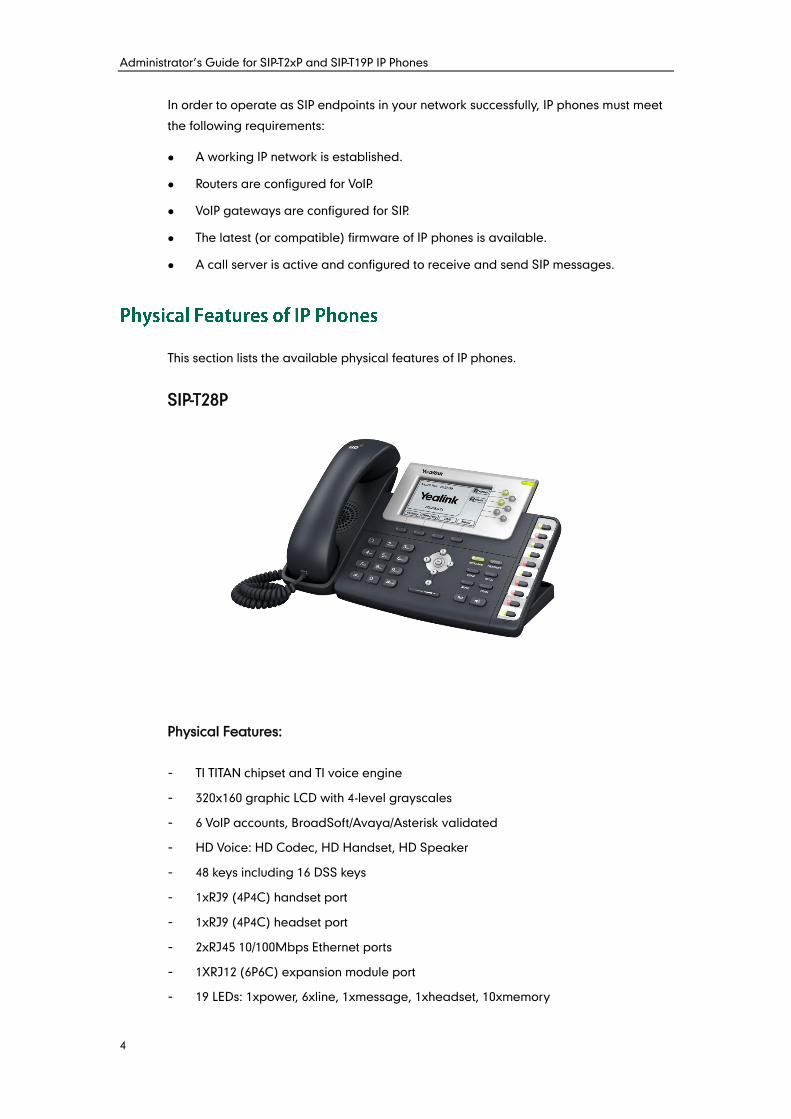
This section lists the available physical features of IP phones.
SIP-T28P
Physical Features:
- TI TITAN chipset and TI voice engine
- 320x160 graphic LCD with 4-level grayscales
- 6 VoIP accounts, BroadSoft/Avaya/Asterisk validated
- HD Voice: HD Codec, HD Handset, HD Speaker
- 48 keys including 16 DSS keys
- 1xRJ9 (4P4C) handset port
- 1xRJ9 (4P4C) headset port
- 2xRJ45 10/100Mbps Ethernet ports
- 1XRJ12 (6P6C) expansion module port
- 19 LEDs: 1xpower, 6xline, 1xmessage, 1xheadset, 10xmemory
Product Overview
5
- Power adapter: AC 100~240V input and DC 5V/1.2A output
- Power over Ethernet (IEEE 802.3af)
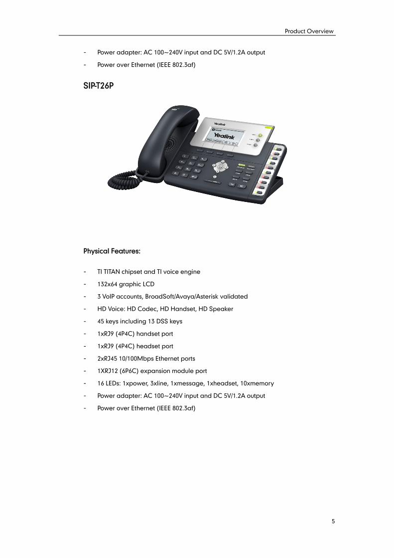
SIP-T26P
Physical Features:
- TI TITAN chipset and TI voice engine
- 132x64 graphic LCD
- 3 VoIP accounts, BroadSoft/Avaya/Asterisk validated
- HD Voice: HD Codec, HD Handset, HD Speaker
- 45 keys including 13 DSS keys
- 1xRJ9 (4P4C) handset port
- 1xRJ9 (4P4C) headset port
- 2xRJ45 10/100Mbps Ethernet ports
- 1XRJ12 (6P6C) expansion module port
- 16 LEDs: 1xpower, 3xline, 1xmessage, 1xheadset, 10xmemory
- Power adapter: AC 100~240V input and DC 5V/1.2A output
- Power over Ethernet (IEEE 802.3af)
Administrator’s Guide for SIP-T2xP and SIP-T19P IP Phones
6
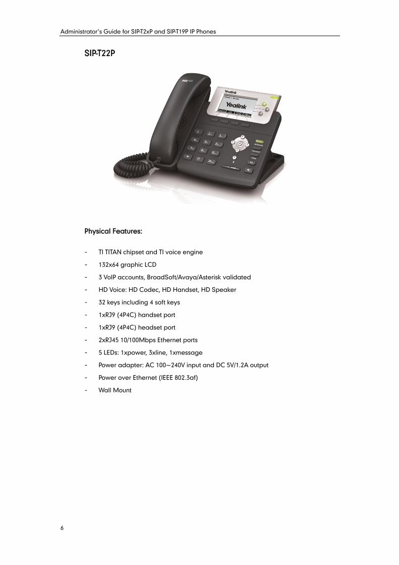
SIP-T22P
Physical Features:
- TI TITAN chipset and TI voice engine
- 132x64 graphic LCD
- 3 VoIP accounts, BroadSoft/Avaya/Asterisk validated
- HD Voice: HD Codec, HD Handset, HD Speaker
- 32 keys including 4 soft keys
- 1xRJ9 (4P4C) handset port
- 1xRJ9 (4P4C) headset port
- 2xRJ45 10/100Mbps Ethernet ports
- 5 LEDs: 1xpower, 3xline, 1xmessage
- Power adapter: AC 100~240V input and DC 5V/1.2A output
- Power over Ethernet (IEEE 802.3af)
- Wall Mount
Product Overview
7
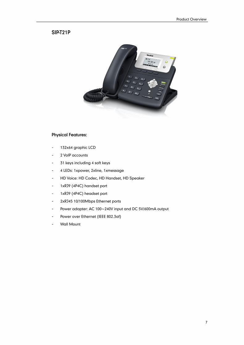
SIP-T21P
Physical Features:
- 132x64 graphic LCD
- 2 VoIP accounts
- 31 keys including 4 soft keys
- 4 LEDs: 1xpower, 2xline, 1xmessage
- HD Voice: HD Codec, HD Handset, HD Speaker
- 1xRJ9 (4P4C) handset port
- 1xRJ9 (4P4C) headset port
- 2xRJ45 10/100Mbps Ethernet ports
- Power adapter: AC 100~240V input and DC 5V/600mA output
- Power over Ethernet (IEEE 802.3af)
- Wall Mount
Administrator’s Guide for SIP-T2xP and SIP-T19P IP Phones
8
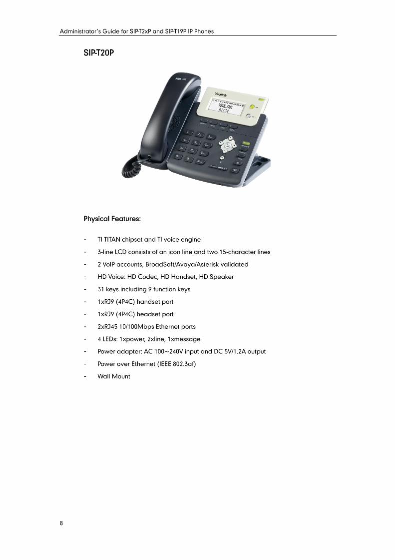
SIP-T20P
Physical Features:
- TI TITAN chipset and TI voice engine
- 3-line LCD consists of an icon line and two 15-character lines
- 2 VoIP accounts, BroadSoft/Avaya/Asterisk validated
- HD Voice: HD Codec, HD Handset, HD Speaker
- 31 keys including 9 function keys
- 1xRJ9 (4P4C) handset port
- 1xRJ9 (4P4C) headset port
- 2xRJ45 10/100Mbps Ethernet ports
- 4 LEDs: 1xpower, 2xline, 1xmessage
- Power adapter: AC 100~240V input and DC 5V/1.2A output
- Power over Ethernet (IEEE 802.3af)
- Wall Mount
Product Overview
9
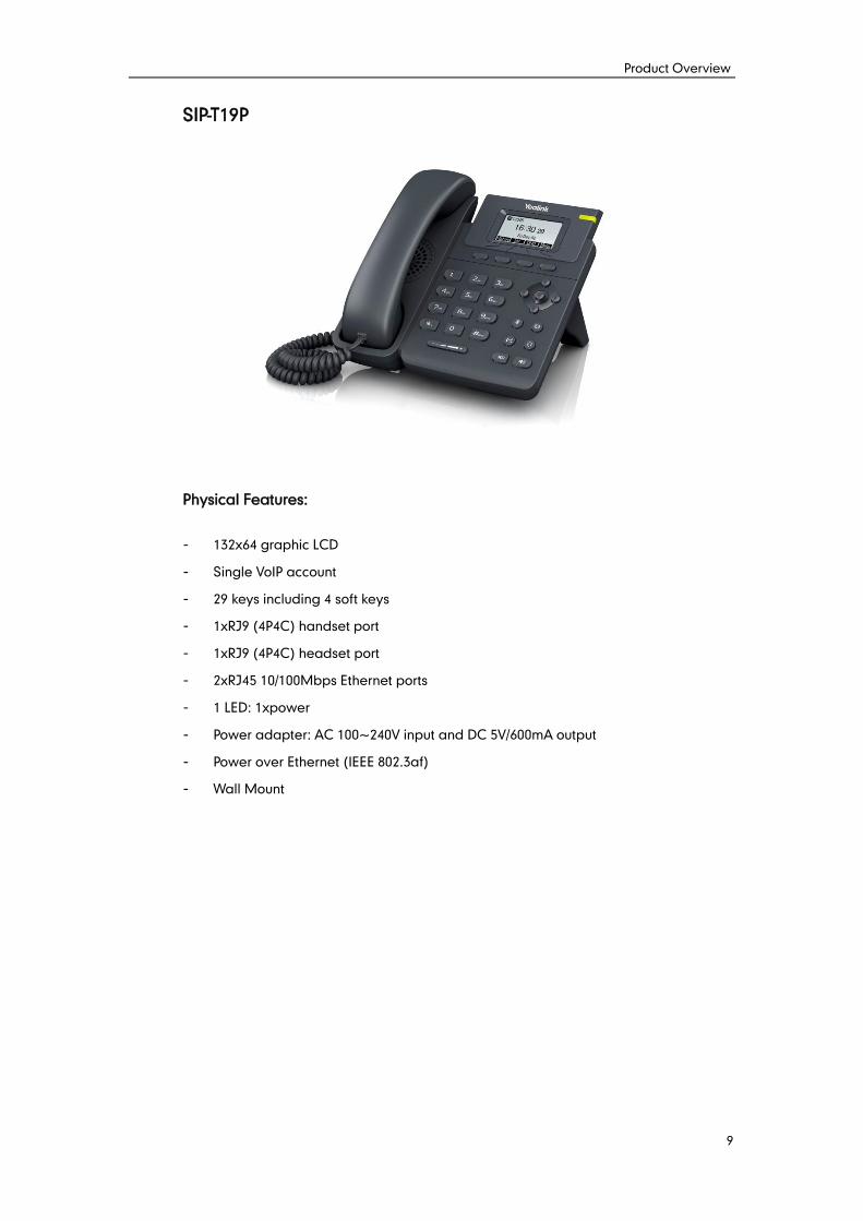
SIP-T19P
Physical Features:
- 132x64 graphic LCD
- Single VoIP account
- 29 keys including 4 soft keys
- 1xRJ9 (4P4C) handset port
- 1xRJ9 (4P4C) headset port
- 2xRJ45 10/100Mbps Ethernet ports
- 1 LED: 1xpower
- Power adapter: AC 100~240V input and DC 5V/600mA output
- Power over Ethernet (IEEE 802.3af)
- Wall Mount
Administrator’s Guide for SIP-T2xP and SIP-T19P IP Phones
10
In addition to physical features introduced above, IP phones also support the following
key features when running the latest firmware:
Phone Features
- Call Options: emergency call, call waiting, call hold, call mute, call forward,
call transfer, call pickup, conference.
- Basic Features: DND, phone lock, auto redial, live dialpad, dial plan, hotline,
caller identity, auto answer.
- Advanced Features: BLF, server redundancy, distinctive ring tones, remote
phone book (not applicable to SIP-T20P IP phones), LDAP (not applicable to
SIP-T19P and SIP-T20P IP phones), 802.1X authentication.
Codecs and Voice Features
- Wideband codec: G.722
- Narrowband codec: G.711, G.723, G.726, G.729AB, iLBC
- VAD, CNG, AEC, PLC, AJB, AGC
- Full-duplex speakerphone with AEC
Network Features
- SIP v1 (RFC2543), v2 (RFC3261)
- NAT Traversal: STUN mode
- DTMF: INBAND, RFC2833, SIP INFO
- Proxy mode and peer-to-peer SIP link mode
- IP assignment: Static/DHCP/PPPoE
- VLAN assignment: LLDP/Static/DHCP
- Bridge/Router mode for PC port (Router mode is not applicable to SIP-T19P and
SIP-T21P IP phones)
- TFTP/DHCP/PPPoE client
- HTTP/HTTPS server
- DNS client
- NAT/DHCP server
- IPv6 support
Management
- FTP/TFTP/HTTP/PnP auto-provision
- Configuration: browser/phone/auto-provision
- Direct IP call without SIP proxy
- Dial number via SIP server
Product Overview
11
- Dial URL via SIP server
- TR-069
Security
- HTTPS (server/client)
- SRTP (RFC3711)
- Transport Layer Security (TLS)
- VLAN (802.1q), QoS
- Digest authentication using MD5/MD5-sess
- Secure configuration file via AES encryption
- Phone lock for personal privacy protection
- Admin/User configuration mode

Administrator’s Guide for SIP-T2xP and SIP-T19P IP Phones
12
Getting Started
13
This chapter provides basic information and installation instructions of IP phones.
This chapter provides the following sections:
Connecting the IP Phones
Initialization Process Overview
Verifying Startup
Reading Icons
Configuration Methods
Configuring Basic Network Parameters
Upgrading Firmware
Reading Icons
This section introduces how to install IP phones with components in packaging contents.
1. Attach the stand
2. Connect the handset and optional headset
3. Connect the network and power
Note
A headset is not included in packaging contents.
Administrator’s Guide for SIP-T2xP and SIP-T19P IP Phones
14
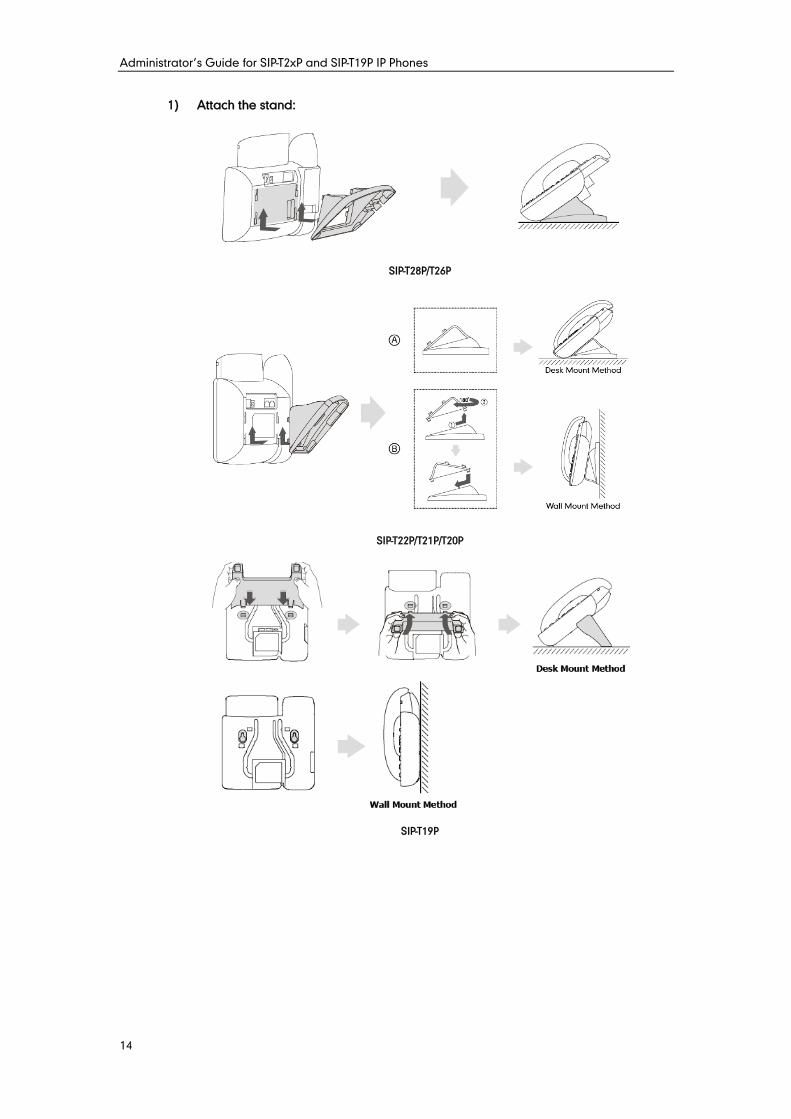
1) Attach the stand:
SIP-T28P/T26P
SIP-T22P/T21P/T20P
SIP-T19P
Getting Started
15
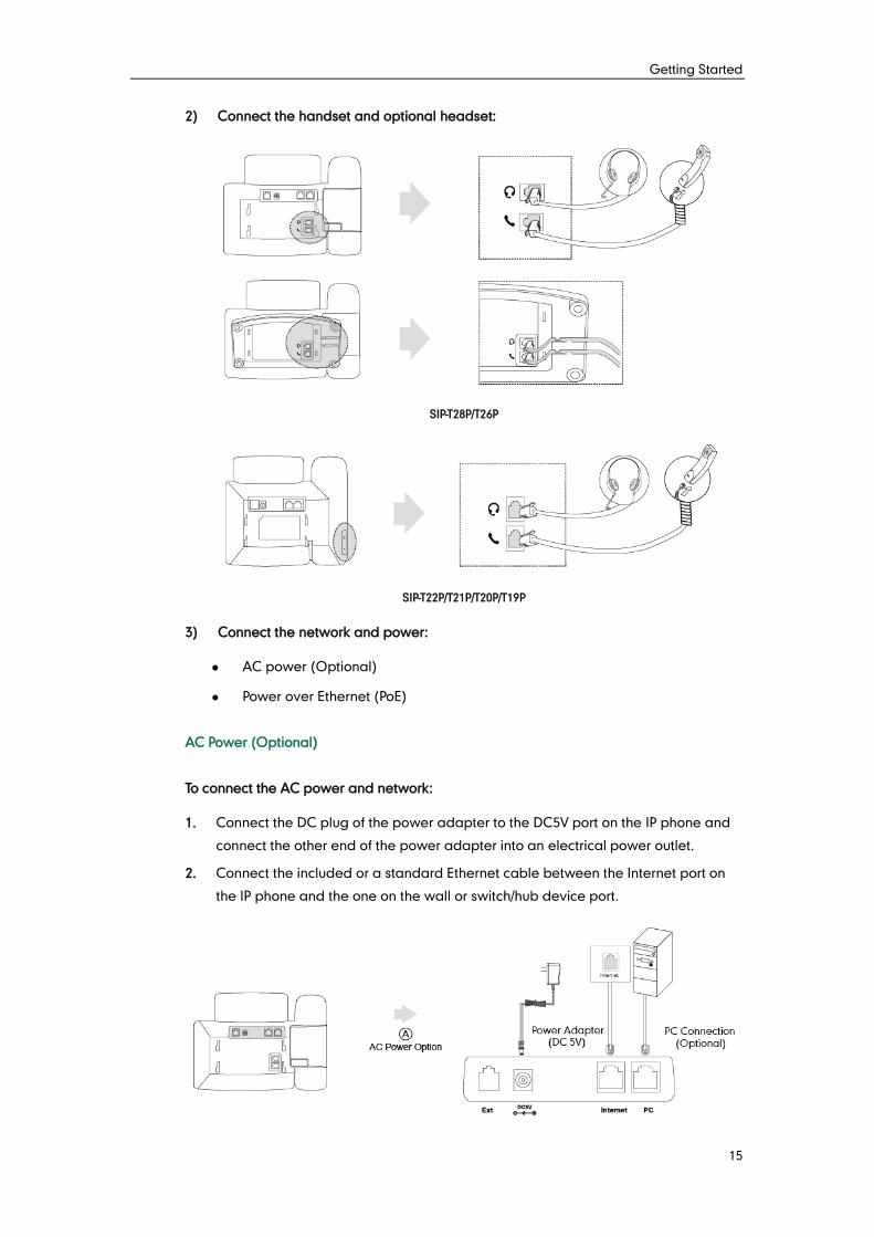
2) Connect the handset and optional headset:
SIP-T28P/T26P
SIP-T22P/T21P/T20P/T19P
3) Connect the network and power:
AC power (Optional)
Power over Ethernet (PoE)
AC Power (Optional)
To connect the AC power and network:
1. Connect the DC plug of the power adapter to the DC5V port on the IP phone and
connect the other end of the power adapter into an electrical power outlet.
2. Connect the included or a standard Ethernet cable between the Internet port on
the IP phone and the one on the wall or switch/hub device port.
Administrator’s Guide for SIP-T2xP and SIP-T19P IP Phones
16
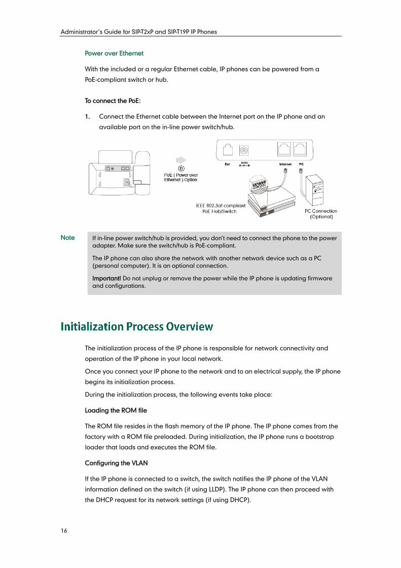
Power over Ethernet
With the included or a regular Ethernet cable, IP phones can be powered from a
PoE-compliant switch or hub.
To connect the PoE:
1. Connect the Ethernet cable between the Internet port on the IP phone and an
available port on the in-line power switch/hub.
Note
The initialization process of the IP phone is responsible for network connectivity and
operation of the IP phone in your local network.
Once you connect your IP phone to the network and to an electrical supply, the IP phone
begins its initialization process.
During the initialization process, the following events take place:
Loading the ROM file
The ROM file resides in the flash memory of the IP phone. The IP phone comes from the
factory with a ROM file preloaded. During initialization, the IP phone runs a bootstrap
loader that loads and executes the ROM file.
Configuring the VLAN
If the IP phone is connected to a switch, the switch notifies the IP phone of the VLAN
information defined on the switch (if using LLDP). The IP phone can then proceed with
the DHCP request for its network settings (if using DHCP).
If in-line power switch/hub is provided, you don’t need to connect the phone to the power
adapter. Make sure the switch/hub is PoE-compliant.
The IP phone can also share the network with another network device such as a PC
(personal computer). It is an optional connection.
Important! Do not unplug or remove the power while the IP phone is updating firmware
and configurations.
Getting Started
17
Querying the DHCP (Dynamic Host Configuration Protocol) Server
The IP phone is capable of querying a DHCP server. DHCP is enabled on the IP phone
by default. The following network parameters can be obtained from the DHCP server
during initialization:
IP Address
Subnet Mask
Gateway
Primary DNS (Domain Name Server)
Secondary DNS
You need to configure network parameters of the IP phone manually if any of them is not
supplied by the DHCP server. For more information on configuring network parameters
manually, refer to Configuring Network Parameters Manually on page 25.
Contacting the provisioning server
If the IP phone is configured to obtain configurations from the provisioning server, it will
connect to the provisioning server and download the configuration file(s) during startup.
The IP phone will be able to resolve and update configurations written in the
configuration file(s). If the IP phone does not obtain configurations from the provisioning
server, the IP phone will use configurations stored in the flash memory.
Updating firmware
If the access URL of firmware is defined in the configuration file, the IP phone will
download firmware from the provisioning server. If the MD5 value of the downloaded
firmware file differs from that of the image stored in the flash memory, the IP phone will
perform a firmware update.
Downloading the resource files
In addition to configuration file(s), the IP phone may require resource files before it can
deliver service. These resource files are optional, but if some particular features are
being deployed, these files are required.
The followings show examples of resource files:
Language packs
Ring tones
Contact files
After connected to the power and network, the IP phone begins the initializing process
by cycling through the following steps:
1. The power indicator LED illuminates.
Administrator’s Guide for SIP-T2xP and SIP-T19P IP Phones
18
2. The message “Initializing, Please Wait” appears on the LCD screen when the IP
phone starts up.
3. The main LCD screen displays the following:
Time and date
Soft key labels (not applicable to SIP-T20P IP phones)
4. Press the OK key to check the IP phone status, the LCD screen displays the valid IP
address, MAC address, firmware version, etc.
If the IP phone has successfully passed through these steps, it starts up properly and is
ready for use.
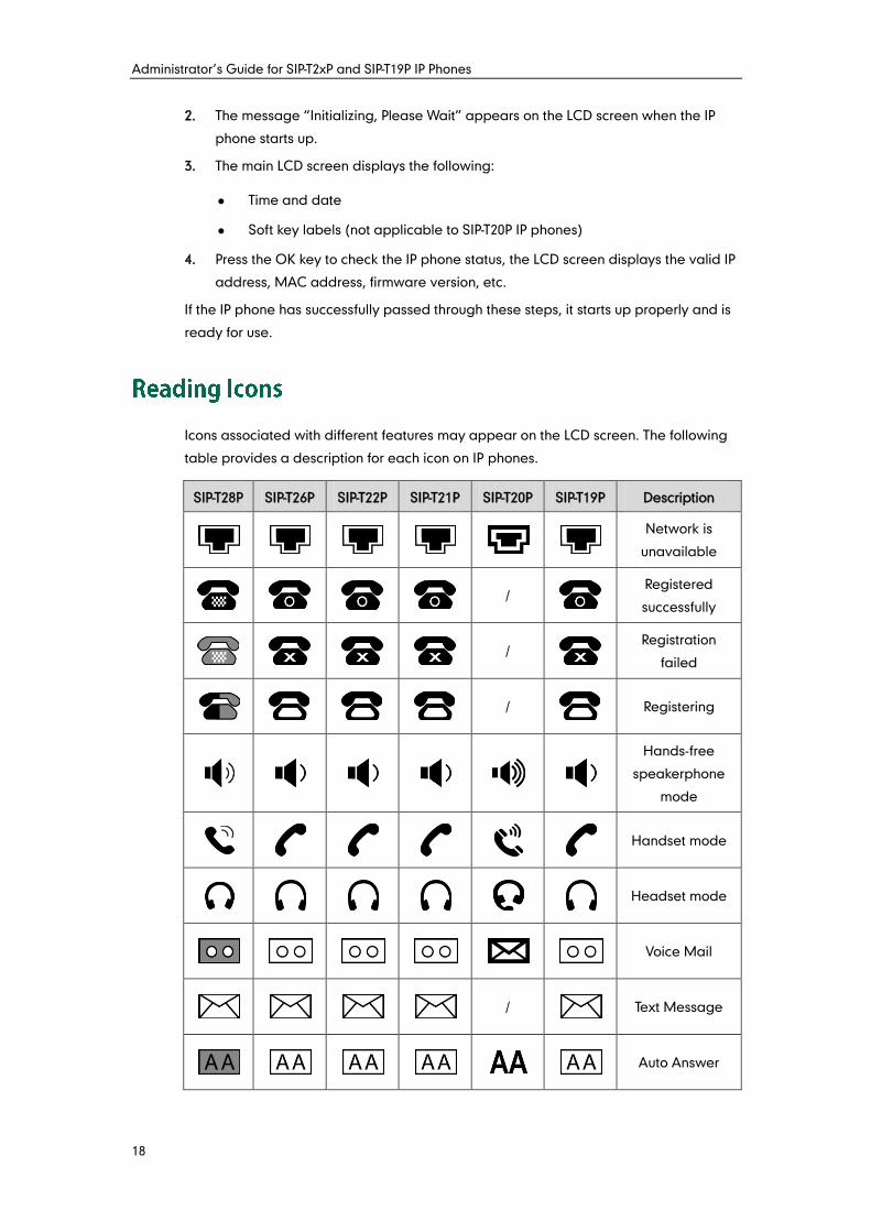
Icons associated with different features may appear on the LCD screen. The following
table provides a description for each icon on IP phones.
SIP-T28P SIP-T26P SIP-T22P SIP-T21P SIP-T20P SIP-T19P Description
Network is
unavailable
/
Registered
successfully
/
Registration
failed
/
Registering
Hands-free
speakerphone
mode
Handset mode
Headset mode
Voice Mail
/
Text Message
Auto Answer
Getting Started
19
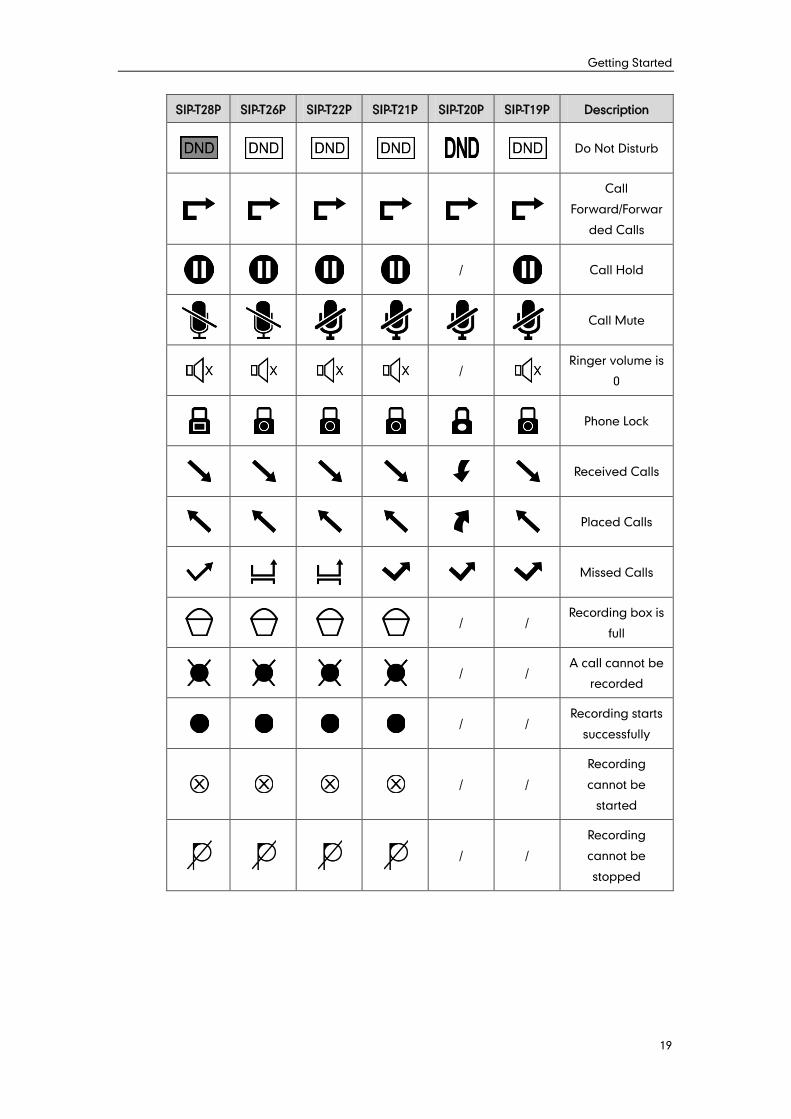
SIP-T28P SIP-T26P SIP-T22P SIP-T21P SIP-T20P SIP-T19P Description
Do Not Disturb
Call
Forward/Forwar
ded Calls
/
Call Hold
Call Mute
/
Ringer volume is
0
Phone Lock
Received Calls
Placed Calls
Missed Calls
/ /
Recording box is
full
/ /
A call cannot be
recorded
/ / Recording starts
successfully
/ /
Recording
cannot be
started
/ /
Recording
cannot be
stopped
Administrator’s Guide for SIP-T2xP and SIP-T19P IP Phones
20
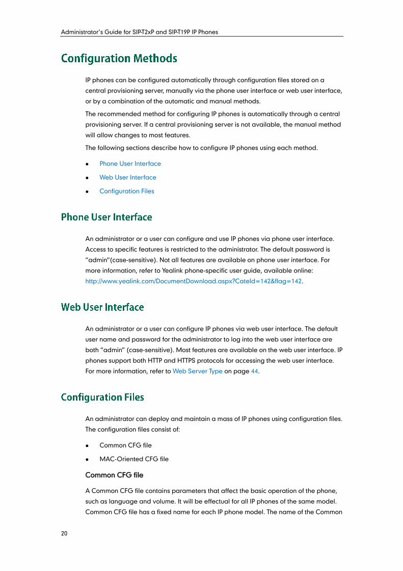
IP phones can be configured automatically through configuration files stored on a
central provisioning server, manually via the phone user interface or web user interface,
or by a combination of the automatic and manual methods.
The recommended method for configuring IP phones is automatically through a central
provisioning server. If a central provisioning server is not available, the manual method
will allow changes to most features.
The following sections describe how to configure IP phones using each method.
Phone User Interface
Web User Interface
Configuration Files
An administrator or a user can configure and use IP phones via phone user interface.
Access to specific features is restricted to the administrator. The default password is
“admin“(case-sensitive). Not all features are available on phone user interface. For
more information, refer to Yealink phone-specific user guide, available online:
http://www.yealink.com/DocumentDownload.aspx?CateId=142&flag=142.
An administrator or a user can configure IP phones via web user interface. The default
user name and password for the administrator to log into the web user interface are
both “admin” (case-sensitive). Most features are available on the web user interface. IP
phones support both HTTP and HTTPS protocols for accessing the web user interface.
For more information, refer to Web Server Type on page 44.
An administrator can deploy and maintain a mass of IP phones using configuration files.
The configuration files consist of:
Common CFG file
MAC-Oriented CFG file
Common CFG file
A Common CFG file contains parameters that affect the basic operation of the phone,
such as language and volume. It will be effectual for all IP phones of the same model.
Common CFG file has a fixed name for each IP phone model. The name of the Common
Getting Started
21
CFG file for each IP phone model is:
SIP-T28P: y000000000000.cfg
SIP-T26P: y000000000004.cfg
SIP-T22P: y000000000005.cfg
SIP-T21P: y000000000034.cfg
SIP-T20P: y000000000007.cfg
SIP-T19P: y000000000031.cfg
MAC-Oriented CFG file
A MAC-Oriented CFG file contains parameters unique to a particular phone. It will only
be effectual for a specific IP phone. The MAC-Oriented CFG file is named after the MAC
address of the IP phone. For example, if the MAC address of a SIP-T22P IP phone is
001565113af8, the name of the MAC-Oriented CFG file must be 001565113af8.cfg.
Central Provisioning
IP phones can be centrally provisioned from a provisioning server using the
configuration files (<y0000000000xx>.cfg and <MAC>.cfg). IP phones support
downloading configuration files using any of the following protocols: FTP, TFTP, HTTP and
HTTPS. You can use a text-based editing application to edit configuration files, and then
store configuration files to a provisioning server.
IP phones can obtain the address of the provisioning server during startup through one
of the following processes: Zero Touch, PnP, DHCP Options and Phone Flash. Then IP
phones download configuration files from the provisioning server, resolve and update
the configurations written in configuration files. This entire process is called auto
provisioning. For more information on auto provisioning, refer to
Yealink_SIP-T2_Series_T19P_T4_Series_IP_Phones_Auto_Provisioning_Guide, available
online: http://www.yealink.com/DocumentDownload.aspx?CateId=142&flag=142.
When modifying parameters, learn the following:
Parameters in configuration files override those stored in the IP phone’s flash
memory by default.
The .cfg extension of configuration files must be in lowercase.
Each line in a configuration file must use the following format and adhere to
the following rules:
variable-name = value
- Associate only one value with one variable.
- Separate each variable name and value with an equal sign.
- Set only one variable per line.
- Put the variable and value on the same line, and do not break the line.
- Comment the variable on a separated line. Use the pound (#) delimiter to
Administrator’s Guide for SIP-T2xP and SIP-T19P IP Phones
22
distinguish the comments.
In order to get your IP phones running, you must perform basic network setup, such as IP
address and subnet mask configuration. This section describes how to configure basic
network parameters for IP phones.
Note
DHCP (Dynamic Host Configuration Protocol) is a network protocol used to dynamically
allocate network parameters to network hosts. The automatic allocation of network
parameters to hosts eases the administrative burden of maintaining an IP network. IP
phones comply with the DHCP specifications documented in RFC 2131. If using DHCP, IP
phones connected to the network become operational without having to be manually
assigned IP addresses and additional network parameters. Static DNS address(es) can
be configured and used when DHCP is enabled.
DHCP Option
DHCP provides a framework for passing information to TCP/IP network devices. Network
and other control information are carried in tagged data items that are stored in the
options field of the DHCP message. The data items themselves are also called options.
DHCP can be initiated by simply connecting the IP phone with the network. IP phones
broadcast DISCOVER messages to request the network information carried in DHCP
options, and the DHCP server responds with specific values in corresponding options.
The following table lists common DHCP options supported by IP phones.
Parameter DHCP Option Description
Subnet Mask 1 Specify the client’s subnet mask.
Time Offset 2
Specify the offset of the client's subnet in
seconds from Coordinated Universal Time
(UTC).
Router 3 Specify a list of IP addresses for routers on the
client’s subnet.
Time Server 4 Specify a list of time servers available to the
client.
Domain Name 6 Specify a list of domain name servers
This section mainly introduces IPv4 network parameters. IP phones also support IPv6. For
more information on IPv6, refer to IPv6 Support on page 206.
Getting Started
23
Parameter DHCP Option Description
Server available to the client.
Log Server 7 Specify a list of MIT-LCS UDP servers
available to the client.
Host Name 12 Specify the name of the client.
Domain Server 15 Specify the domain name that client should
use when resolving hostnames via DNS.
Broadcast
Address 28
Specify the broadcast address in use on the
client's subnet.
Network Time
Protocol
Servers
42 Specify a list of NTP servers available to the
client by IP address.
Vendor-Specific
Information 43 Identify the vendor-specific information.
Vendor Class
Identifier 60 Identify the vendor type.
TFTP Server
Name 66
Identify a TFTP server when the 'sname' field
in the DHCP header has been used for DHCP
options.
Boot file Name 67
Identify a boot file when the 'file' field in the
DHCP header has been used for DHCP
options.
For more information on DHCP options, refer to
http://www.ietf.org/rfc/rfc2131.txt?number=2131 or
http://www.ietf.org/rfc/rfc2132.txt?number=2132.
If you do not have the ability to configure the DHCP options for discovering the
provisioning server on the DHCP server, an alternate method of automatically
discovering the provisioning server address is required. Connecting to the secondary
DHCP server that responds to DHCP INFORM queries with a requested provisioning
server address is one possibility. For more information, refer to
http://www.ietf.org/rfc/rfc3925.txt?number=3925.
Procedure
DHCP can be configured using the configuration files or locally.
Configuration File <y0000000000xx>.cfg
Configure DHCP on the IP phone.
Configure static DNS address
when DHCP is used.
For more information, refer to
Administrator’s Guide for SIP-T2xP and SIP-T19P IP Phones
24
DHCP on page 270.
Local
Web User Interface
Configure DHCP on the IP phone.
Configure static DNS address
when DHCP is used.
Navigate to:
http://<phoneIPAddress>/servlet
?p=network&q=load
Phone User Interface Configure DHCP on the IP phone.
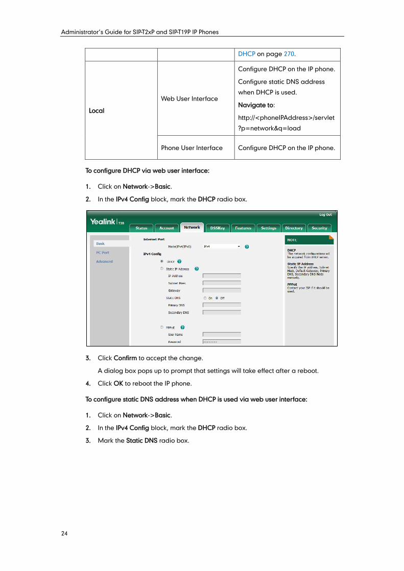
To configure DHCP via web user interface:
1. Click on Network->Basic.
2. In the IPv4 Config block, mark the DHCP radio box.
3. Click Confirm to accept the change.
A dialog box pops up to prompt that settings will take effect after a reboot.
4. Click OK to reboot the IP phone.
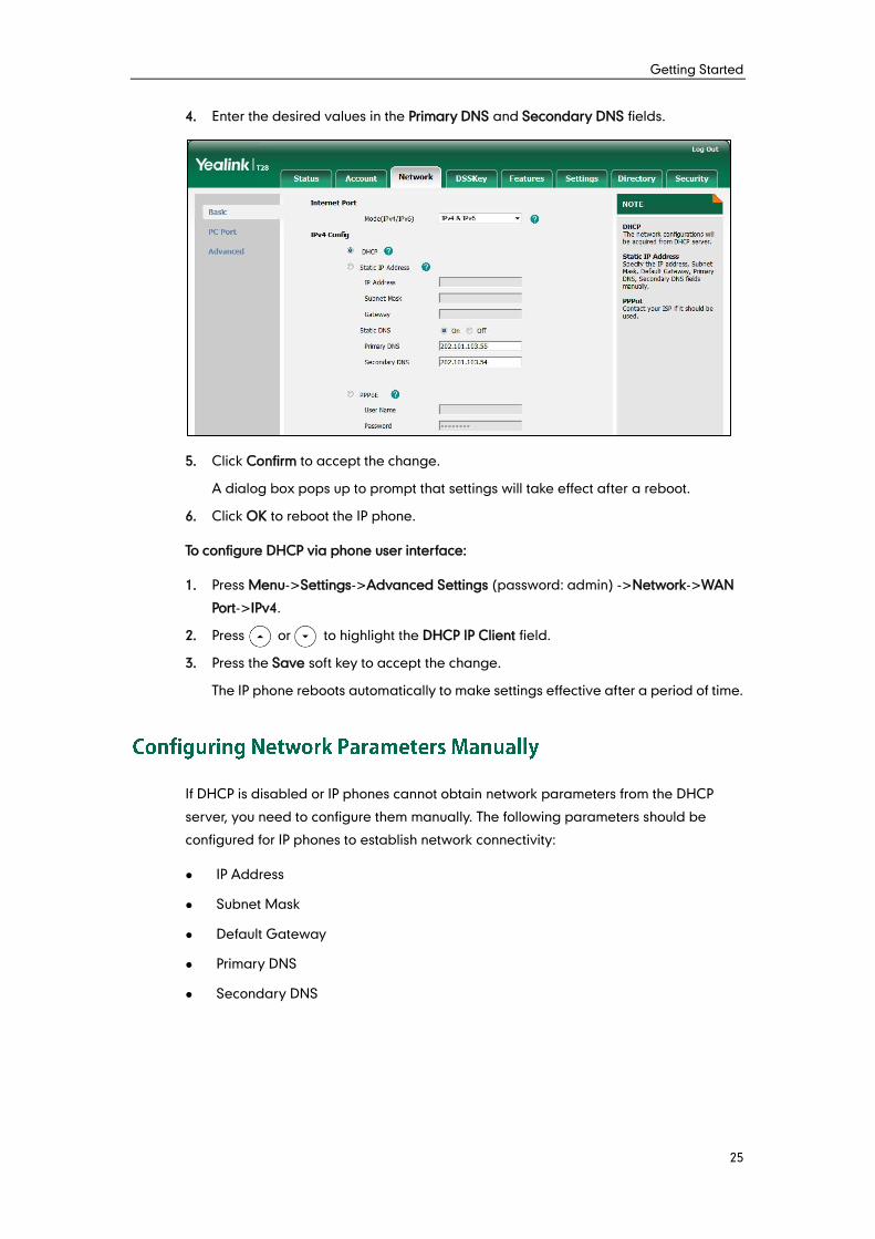
To configure static DNS address when DHCP is used via web user interface:
1. Click on Network->Basic.
2. In the IPv4 Config block, mark the DHCP radio box.
3. Mark the Static DNS radio box.
Getting Started
25
4. Enter the desired values in the Primary DNS and Secondary DNS fields.
5. Click Confirm to accept the change.
A dialog box pops up to prompt that settings will take effect after a reboot.
6. Click OK to reboot the IP phone.
To configure DHCP via phone user interface:
1. Press Menu->Settings->Advanced Settings (password: admin) ->Network->WAN
Port->IPv4.
2. Press or to highlight the DHCP IP Client field.
3. Press the Save soft key to accept the change.
The IP phone reboots automatically to make settings effective after a period of time.
If DHCP is disabled or IP phones cannot obtain network parameters from the DHCP
server, you need to configure them manually. The following parameters should be
configured for IP phones to establish network connectivity:
IP Address
Subnet Mask
Default Gateway
Primary DNS
Secondary DNS
Administrator’s Guide for SIP-T2xP and SIP-T19P IP Phones
26
Procedure
Network parameters can be configured manually using the configuration files or
locally.
Configuration File <y0000000000xx>.cfg
Configure network parameters of
the IP phone manually.
For more information, refer to
Static Network Settings on page
271.
Local
Web User Interface
Configure network parameters of
the IP phone manually.
Navigate to:
http://<phoneIPAddress>/servlet
?p=network&q=load
Phone User Interface Configure network parameters of
the IP phone manually.
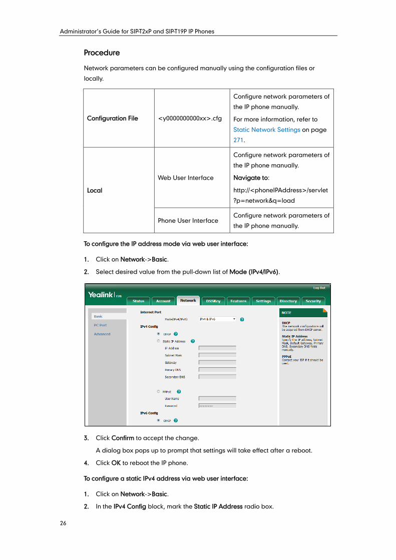
To configure the IP address mode via web user interface:
1. Click on Network->Basic.
2. Select desired value from the pull-down list of Mode (IPv4/IPv6).
3. Click Confirm to accept the change.
A dialog box pops up to prompt that settings will take effect after a reboot.
4. Click OK to reboot the IP phone.
To configure a static IPv4 address via web user interface:
1. Click on Network->Basic.
2. In the IPv4 Config block, mark the Static IP Address radio box.
Getting Started
27
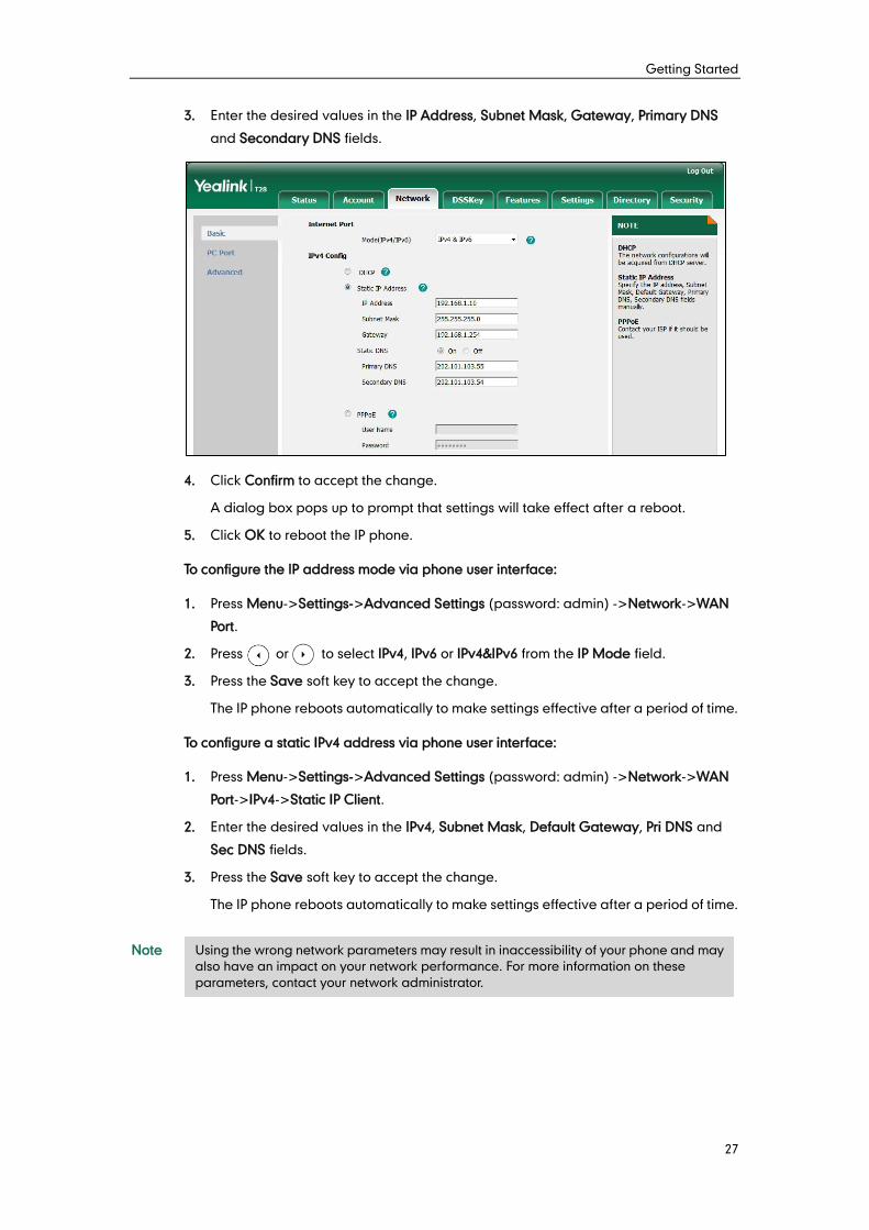
3. Enter the desired values in the IP Address, Subnet Mask, Gateway, Primary DNS
and Secondary DNS fields.
4. Click Confirm to accept the change.
A dialog box pops up to prompt that settings will take effect after a reboot.
5. Click OK to reboot the IP phone.
To configure the IP address mode via phone user interface:
1. Press Menu->Settings->Advanced Settings (password: admin) ->Network->WAN
Port.
2. Press or to select IPv4, IPv6 or IPv4&IPv6 from the IP Mode field.
3. Press the Save soft key to accept the change.
The IP phone reboots automatically to make settings effective after a period of time.
To configure a static IPv4 address via phone user interface:
1. Press Menu->Settings->Advanced Settings (password: admin) ->Network->WAN
Port->IPv4->Static IP Client.
2. Enter the desired values in the IPv4, Subnet Mask, Default Gateway, Pri DNS and
Sec DNS fields.
3. Press the Save soft key to accept the change.
The IP phone reboots automatically to make settings effective after a period of time.
Note
Using the wrong network parameters may result in inaccessibility of your phone and may
also have an impact on your network performance. For more information on these
parameters, contact your network administrator.
Administrator’s Guide for SIP-T2xP and SIP-T19P IP Phones
28
PPPoE (Point-to-Point Protocol over Ethernet) is a network protocol used by Internet
Service Providers (ISPs) to provide Digital Subscriber Line (DSL) high speed Internet
services. PPPoE allows an office or building-full of users to share a common DSL
connection to the Internet. PPPoE connection is supported by the IP phone Internet port.
Contact your ISP for the PPPoE user name and password.
Procedure
PPPoE can be configured using the configuration files or locally.
Configuration File <y0000000000xx>.cfg
Configure PPPoE on the IP phone.
For more information, refer to
PPPoE on page 274.
Local
Web User Interface
Configure PPPoE on the IP phone.
Navigate to:
http://<phoneIPAddress>/servlet
?p=network&q=load
Phone User Interface Configure PPPoE on the IP phone.
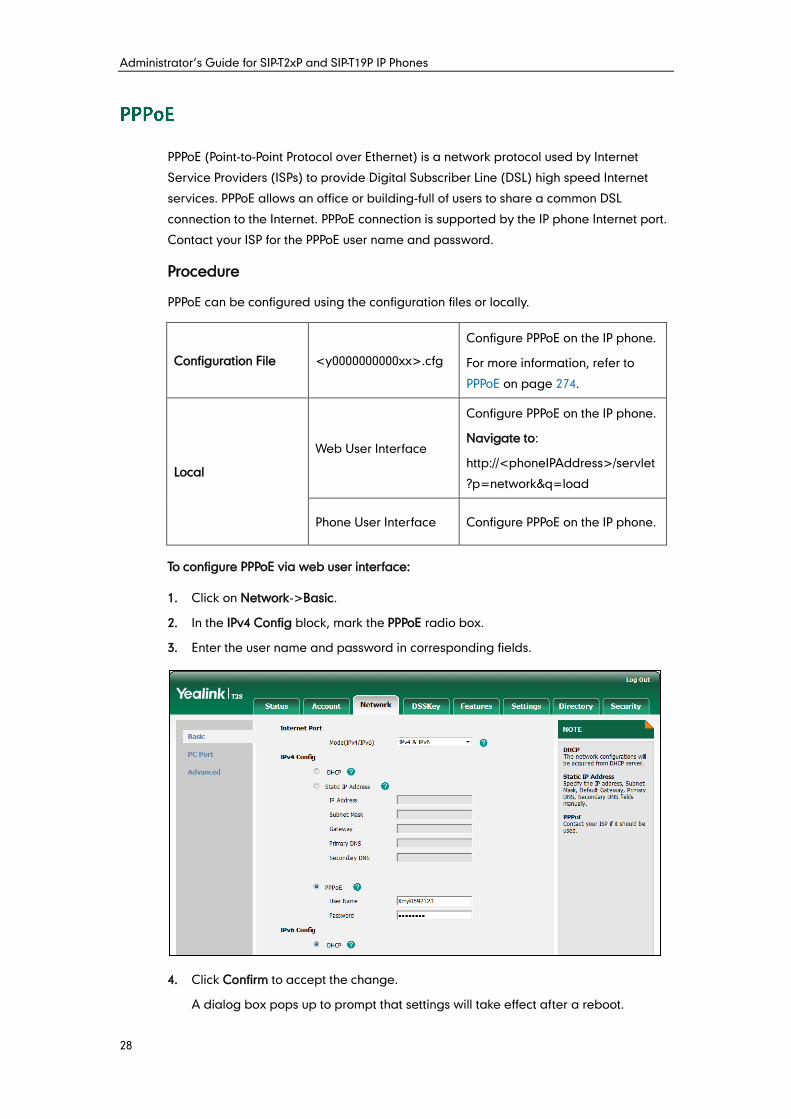
To configure PPPoE via web user interface:
1. Click on Network->Basic.
2. In the IPv4 Config block, mark the PPPoE radio box.
3. Enter the user name and password in corresponding fields.
4. Click Confirm to accept the change.
A dialog box pops up to prompt that settings will take effect after a reboot.
Getting Started
29
5. Click OK to reboot the IP phone.
To configure PPPoE via phone user interface:
1. Press Menu->Settings->Advanced Settings (password: admin) ->Network->WAN
Port->IPv4->PPPoE IP Client.
2. Enter the user name and password in corresponding fields.
3. Press the Save soft key to accept the change.
The IP phone reboots automatically to make settings effective after a period of time.
Two Ethernet ports on the back of the IP phone: Internet port and PC port. Three optional
methods of transmission configuration for IP phone Internet or PC Ethernet ports:
Auto-negotiation
Half-duplex
Full-duplex
Auto-negotiation is configured for both Internet and PC ports on the IP phone by default.
Auto-negotiation
Auto-negotiation means that two connected devices choose common transmission
parameters (e.g., speed and duplex mode) to transmit voice or data over Ethernet. This
process entails devices first sharing transmission capabilities and then selecting the
highest performance transmission mode supported by both. You can configure the
Internet port and PC port on the IP phone to automatically negotiate during the
transmission.
Administrator’s Guide for SIP-T2xP and SIP-T19P IP Phones
30
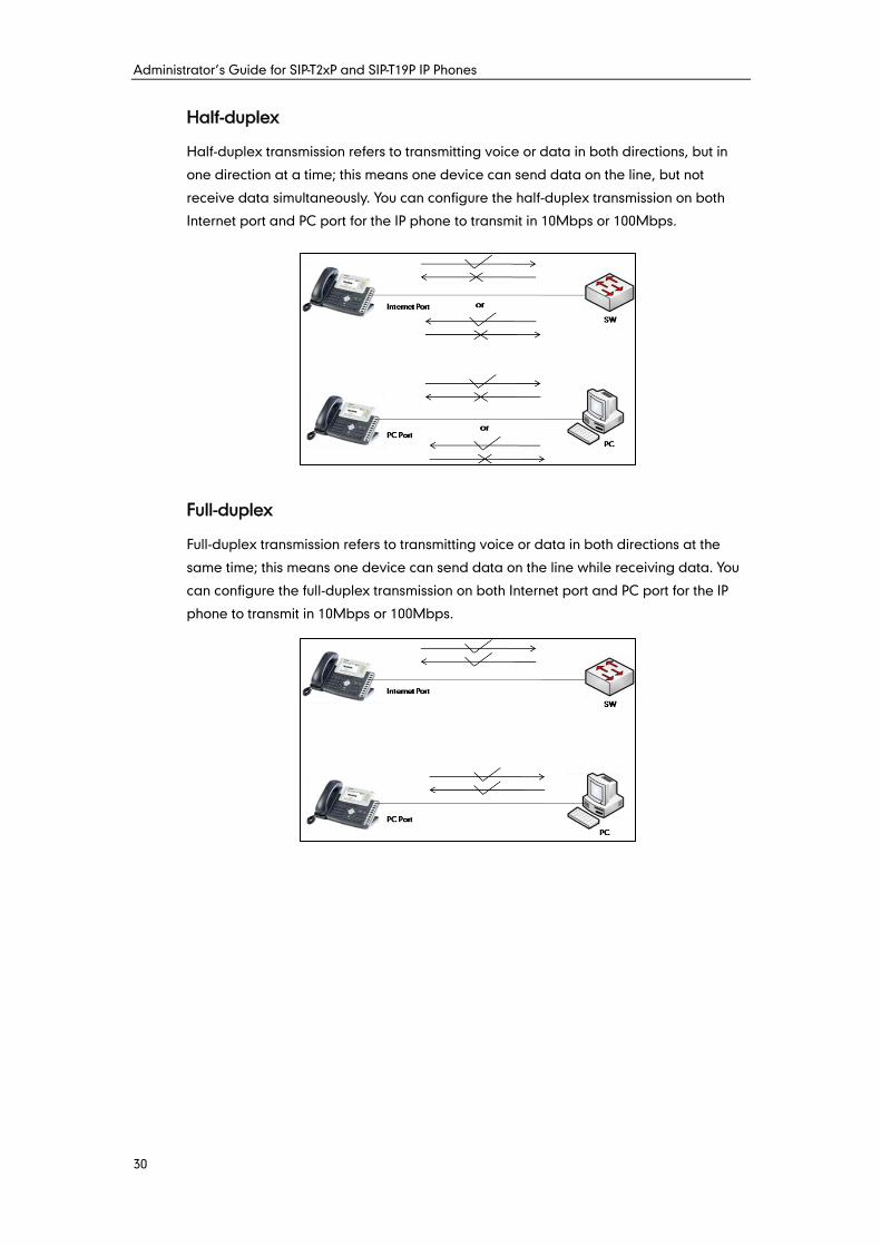
Half-duplex
Half-duplex transmission refers to transmitting voice or data in both directions, but in
one direction at a time; this means one device can send data on the line, but not
receive data simultaneously. You can configure the half-duplex transmission on both
Internet port and PC port for the IP phone to transmit in 10Mbps or 100Mbps.
Full-duplex
Full-duplex transmission refers to transmitting voice or data in both directions at the
same time; this means one device can send data on the line while receiving data. You
can configure the full-duplex transmission on both Internet port and PC port for the IP
phone to transmit in 10Mbps or 100Mbps.
Getting Started
31
Procedure
The transmission methods of Ethernet ports can be configured using the configuration
files or locally.
Configuration File <y0000000000xx>.cfg
Configure the transmission
methods of Ethernet ports.
For more information, refer to
Internet and PC Ports
Transmission Methods on page
275.
Local Web User Interface
Configure the transmission
methods of Ethernet ports.
Navigate to:
http://<phoneIPAddress>/servlet
?p=network-adv&q=load
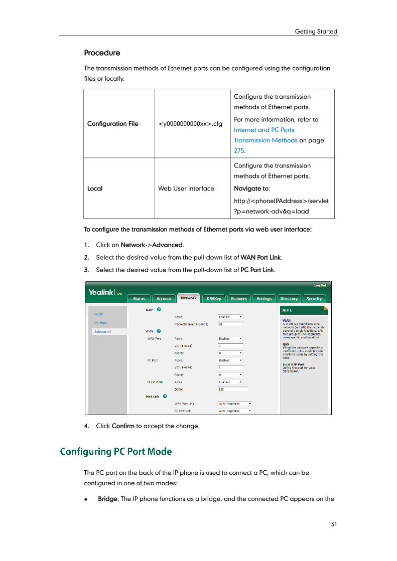
To configure the transmission methods of Ethernet ports via web user interface:
1. Click on Network->Advanced.
2. Select the desired value from the pull-down list of WAN Port Link.
3. Select the desired value from the pull-down list of PC Port Link.
4. Click Confirm to accept the change.
The PC port on the back of the IP phone is used to connect a PC, which can be
configured in one of two modes:
Bridge: The IP phone functions as a bridge, and the connected PC appears on the
Administrator’s Guide for SIP-T2xP and SIP-T19P IP Phones
32
network as a stand-alone device with its own IP address.
Router: The IP phone functions as a router, and provides a DHCP service for the
connected PC.
If the PC port is unused, it can be disabled via web user interface or using configuration
files.
Note
Procedure
PC port mode can be configured using the configuration files or locally.
Configuration File <y0000000000xx>.cfg
Configure the PC port mode.
Disable the PC port.
For more information, refer to PC
Port Mode on page 276.
Local
Web User Interface
Configure the PC port mode.
Disable the PC port.
Navigate to:
http://<phoneIPAddress>/servlet
?p=network-pcport&q=load
Phone User Interface Configure the PC port mode.
To configure the PC port mode via web user interface:
1. Click on Network->PC Port.
2. Select the desired value from the pull-down list of PC Port Active.
3. Mark the desired radio box.
If you mark the As Router radio box, you can configure the IP address for the PC port
and configure DHCP for the PC attached to the PC port.
1) Enter the IP address in the IP Address field.
2) Enter subnet mask in the Subnet Mask field.
3) Select the desired value from the pull-down list of Enable DHCP Server.
4) Enter the start IP address in the Start IP Address field.
The router mode is not applicable to SIP-T19P and SIP-T21P IP phones.
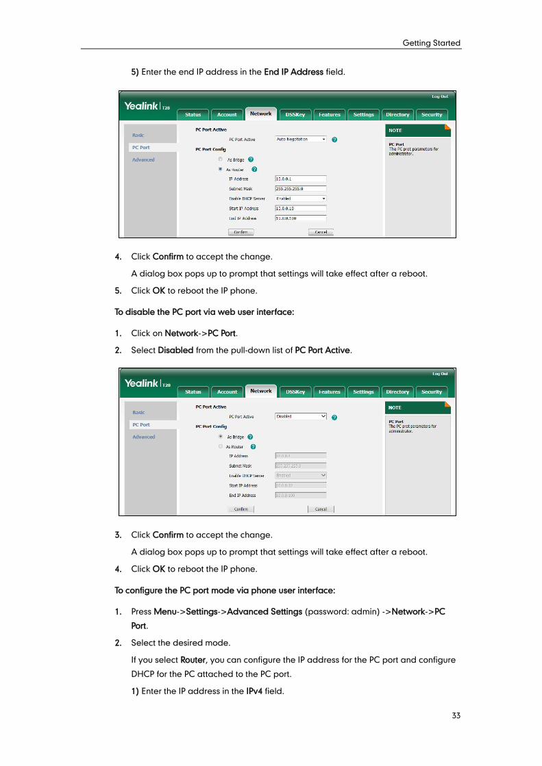
Getting Started
33
5) Enter the end IP address in the End IP Address field.
4. Click Confirm to accept the change.
A dialog box pops up to prompt that settings will take effect after a reboot.
5. Click OK to reboot the IP phone.
To disable the PC port via web user interface:
1. Click on Network->PC Port.
2. Select Disabled from the pull-down list of PC Port Active.
3. Click Confirm to accept the change.
A dialog box pops up to prompt that settings will take effect after a reboot.
4. Click OK to reboot the IP phone.
To configure the PC port mode via phone user interface:
1. Press Menu->Settings->Advanced Settings (password: admin) ->Network->PC
Port.
2. Select the desired mode.
If you select Router, you can configure the IP address for the PC port and configure
DHCP for the PC attached to the PC port.
1) Enter the IP address in the IPv4 field.
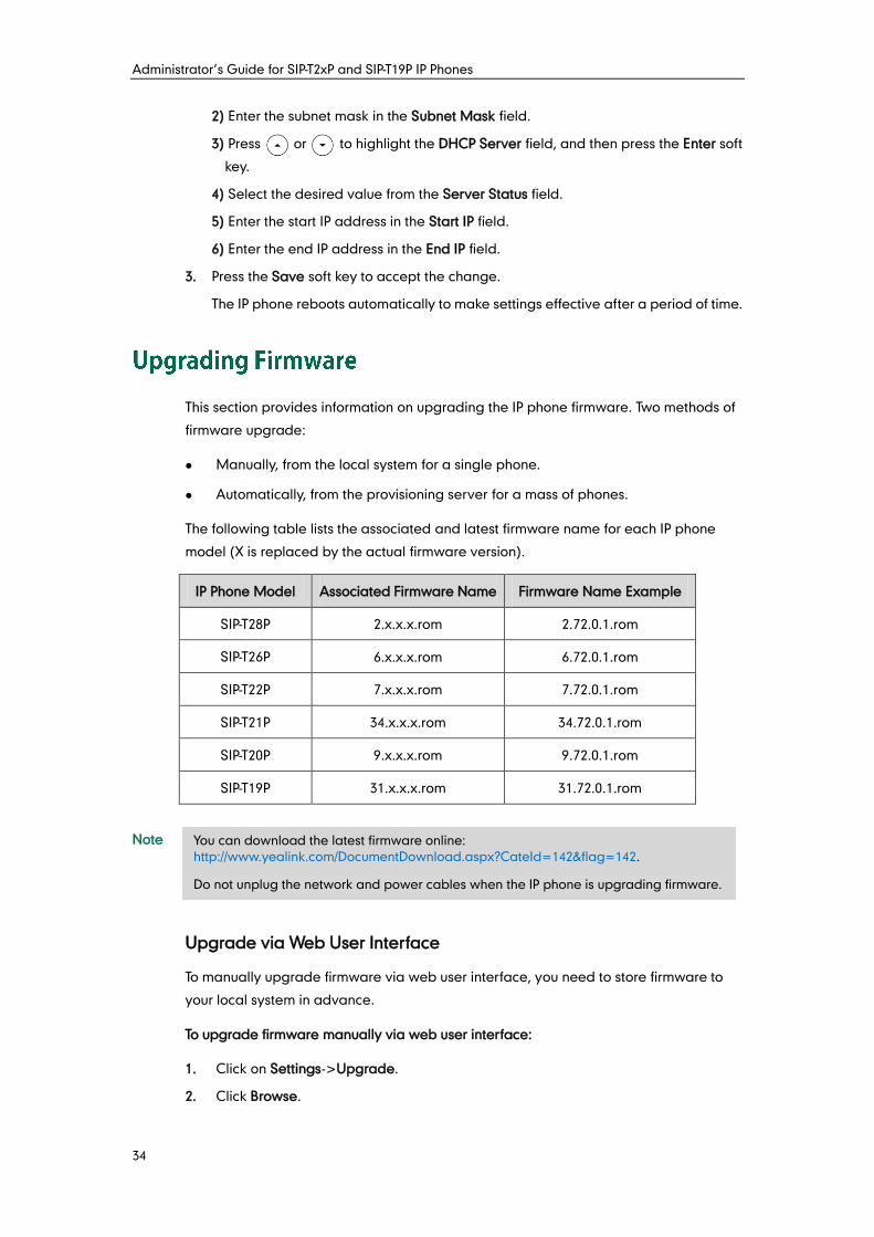
Administrator’s Guide for SIP-T2xP and SIP-T19P IP Phones
34
2) Enter the subnet mask in the Subnet Mask field.
3) Press or to highlight the DHCP Server field, and then press the Enter soft
key.
4) Select the desired value from the Server Status field.
5) Enter the start IP address in the Start IP field.
6) Enter the end IP address in the End IP field.
3. Press the Save soft key to accept the change.
The IP phone reboots automatically to make settings effective after a period of time.
This section provides information on upgrading the IP phone firmware. Two methods of
firmware upgrade:
Manually, from the local system for a single phone.
Automatically, from the provisioning server for a mass of phones.
The following table lists the associated and latest firmware name for each IP phone
model (X is replaced by the actual firmware version).
IP Phone Model Associated Firmware Name Firmware Name Example
SIP-T28P 2.x.x.x.rom 2.72.0.1.rom
SIP-T26P 6.x.x.x.rom 6.72.0.1.rom
SIP-T22P 7.x.x.x.rom 7.72.0.1.rom
SIP-T21P 34.x.x.x.rom 34.72.0.1.rom
SIP-T20P 9.x.x.x.rom 9.72.0.1.rom
SIP-T19P 31.x.x.x.rom 31.72.0.1.rom
Note
Upgrade via Web User Interface
To manually upgrade firmware via web user interface, you need to store firmware to
your local system in advance.
To upgrade firmware manually via web user interface:
1. Click on Settings->Upgrade.
2. Click Browse.
You can download the latest firmware online:
http://www.yealink.com/DocumentDownload.aspx?CateId=142&flag=142.
Do not unplug the network and power cables when the IP phone is upgrading firmware.
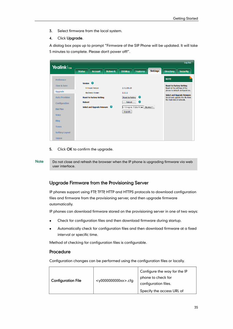
Getting Started
35
3. Select firmware from the local system.
4. Click Upgrade.
A dialog box pops up to prompt “Firmware of the SIP Phone will be updated. It will take
5 minutes to complete. Please don't power off!”.
5. Click OK to confirm the upgrade.
Note
Upgrade Firmware from the Provisioning Server
IP phones support using FTP, TFTP, HTTP and HTTPS protocols to download configuration
files and firmware from the provisioning server, and then upgrade firmware
automatically.
IP phones can download firmware stored on the provisioning server in one of two ways:
Check for configuration files and then download firmware during startup.
Automatically check for configuration files and then download firmware at a fixed
interval or specific time.
Method of checking for configuration files is configurable.
Procedure
Configuration changes can be performed using the configuration files or locally.
Configuration File <y0000000000xx>.cfg
Configure the way for the IP
phone to check for
configuration files.
Specify the access URL of
Do not close and refresh the browser when the IP phone is upgrading firmware via web
user interface.
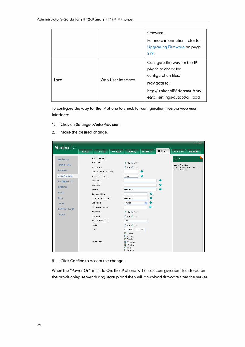
Administrator’s Guide for SIP-T2xP and SIP-T19P IP Phones
36
firmware.
For more information, refer to
Upgrading Firmware on page
279.
Local Web User Interface
Configure the way for the IP
phone to check for
configuration files.
Navigate to:
http://<phoneIPAddress>/servl
et?p=settings-autop&q=load
To configure the way for the IP phone to check for configuration files via web user
interface:
1. Click on Settings->Auto Provision.
2. Make the desired change.
3. Click Confirm to accept the change.
When the “Power On” is set to On, the IP phone will check configuration files stored on
the provisioning server during startup and then will download firmware from the server.
Configuring Basic Features
37
This chapter provides information for making configuration changes for the following
basic features:
Power Indicator LED
Contrast
Backlight
Web Server Type
User Password
Administrator Password
Phone Lock
Time and Date
Language
Logo Customization
Softkey Layout
Key as Send
Dial Plan
Hotline
Directory
Search Source in Dialing
Missed Call Log
Local Directory
Live Dialpad
Call Waiting
Auto Redial
Auto Answer
Call Completion
Anonymous Call
Anonymous Call Rejection
Do Not Disturb
Busy Tone Delay
Return Code When Refuse
Early Media
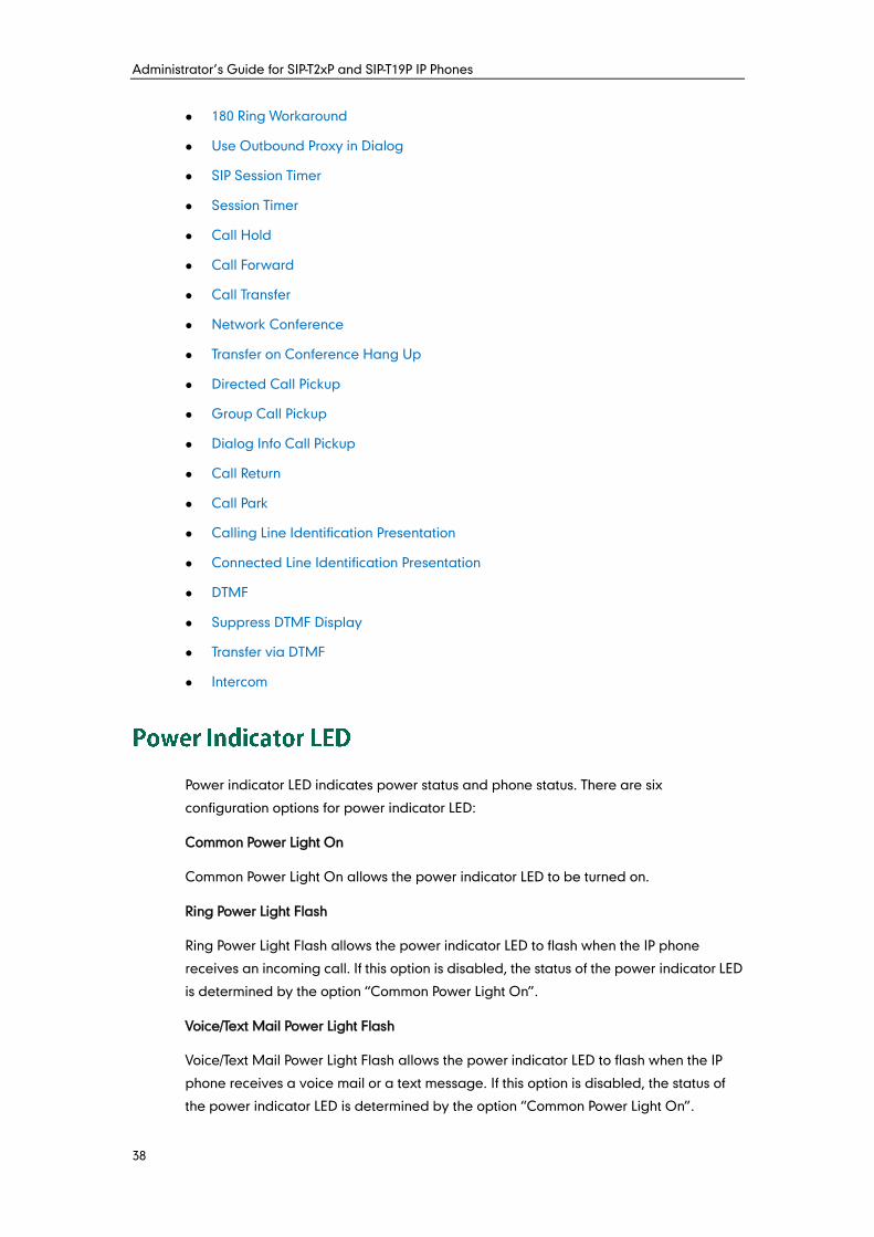
Administrator’s Guide for SIP-T2xP and SIP-T19P IP Phones
38
180 Ring Workaround
Use Outbound Proxy in Dialog
SIP Session Timer
Session Timer
Call Hold
Call Forward
Call Transfer
Network Conference
Transfer on Conference Hang Up
Directed Call Pickup
Group Call Pickup
Dialog Info Call Pickup
Call Return
Call Park
Calling Line Identification Presentation
Connected Line Identification Presentation
DTMF
Suppress DTMF Display
Transfer via DTMF
Intercom
Power indicator LED indicates power status and phone status. There are six
configuration options for power indicator LED:
Common Power Light On
Common Power Light On allows the power indicator LED to be turned on.
Ring Power Light Flash
Ring Power Light Flash allows the power indicator LED to flash when the IP phone
receives an incoming call. If this option is disabled, the status of the power indicator LED
is determined by the option “Common Power Light On”.
Voice/Text Mail Power Light Flash
Voice/Text Mail Power Light Flash allows the power indicator LED to flash when the IP
phone receives a voice mail or a text message. If this option is disabled, the status of
the power indicator LED is determined by the option “Common Power Light On”.
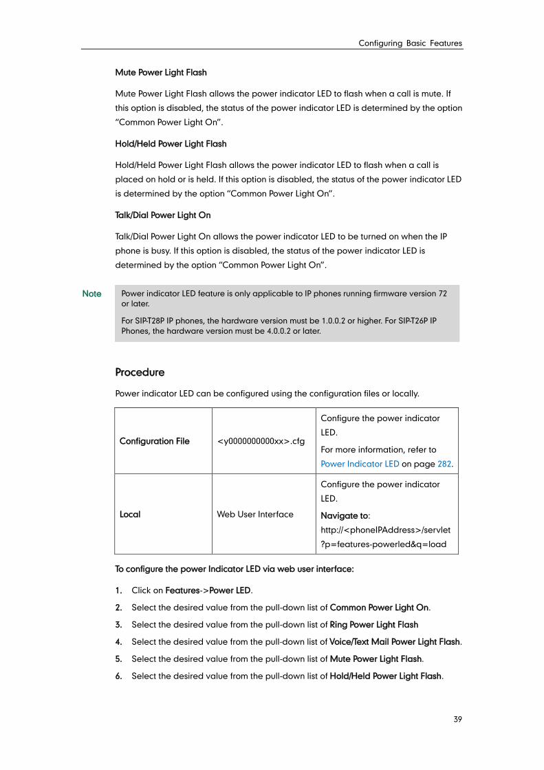
Configuring Basic Features
39
Mute Power Light Flash
Mute Power Light Flash allows the power indicator LED to flash when a call is mute. If
this option is disabled, the status of the power indicator LED is determined by the option
“Common Power Light On”.
Hold/Held Power Light Flash
Hold/Held Power Light Flash allows the power indicator LED to flash when a call is
placed on hold or is held. If this option is disabled, the status of the power indicator LED
is determined by the option “Common Power Light On”.
Talk/Dial Power Light On
Talk/Dial Power Light On allows the power indicator LED to be turned on when the IP
phone is busy. If this option is disabled, the status of the power indicator LED is
determined by the option “Common Power Light On”.
Note
Procedure
Power indicator LED can be configured using the configuration files or locally.
Configuration File <y0000000000xx>.cfg
Configure the power indicator
LED.
For more information, refer to
Power Indicator LED on page 282.
Local Web User Interface
Configure the power indicator
LED.
Navigate to:
http://<phoneIPAddress>/servlet
?p=features-powerled&q=load
To configure the power Indicator LED via web user interface:
1. Click on Features->Power LED.
2. Select the desired value from the pull-down list of Common Power Light On.
3. Select the desired value from the pull-down list of Ring Power Light Flash
4. Select the desired value from the pull-down list of Voice/Text Mail Power Light Flash.
5. Select the desired value from the pull-down list of Mute Power Light Flash.
6. Select the desired value from the pull-down list of Hold/Held Power Light Flash.
Power indicator LED feature is only applicable to IP phones running firmware version 72
or later.
For SIP-T28P IP phones, the hardware version must be 1.0.0.2 or higher. For SIP-T26P IP
Phones, the hardware version must be 4.0.0.2 or later.
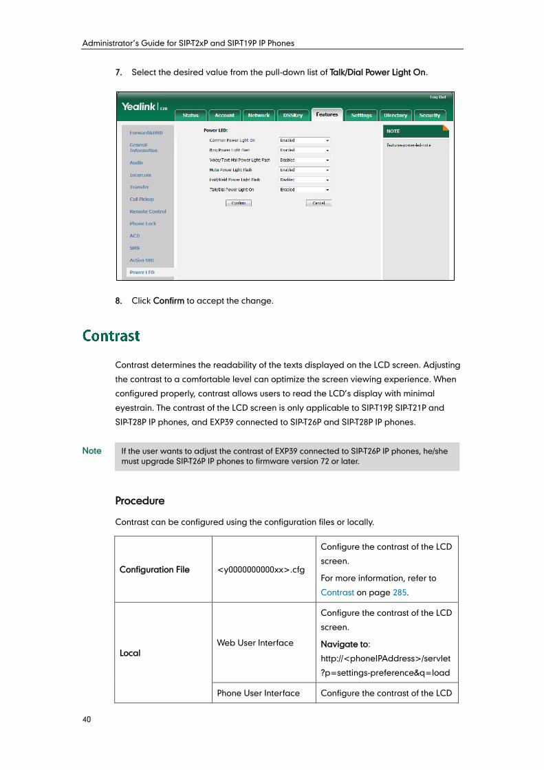
Administrator’s Guide for SIP-T2xP and SIP-T19P IP Phones
40
7. Select the desired value from the pull-down list of Talk/Dial Power Light On.
8. Click Confirm to accept the change.
Contrast determines the readability of the texts displayed on the LCD screen. Adjusting
the contrast to a comfortable level can optimize the screen viewing experience. When
configured properly, contrast allows users to read the LCD’s display with minimal
eyestrain. The contrast of the LCD screen is only applicable to SIP-T19P, SIP-T21P and
SIP-T28P IP phones, and EXP39 connected to SIP-T26P and SIP-T28P IP phones.
Note
Procedure
Contrast can be configured using the configuration files or locally.
Configuration File <y0000000000xx>.cfg
Configure the contrast of the LCD
screen.
For more information, refer to
Contrast on page 285.
Local Web User Interface
Configure the contrast of the LCD
screen.
Navigate to:
http://<phoneIPAddress>/servlet
?p=settings-preference&q=load
Phone User Interface Configure the contrast of the LCD
If the user wants to adjust the contrast of EXP39 connected to SIP-T26P IP phones, he/she
must upgrade SIP-T26P IP phones to firmware version 72 or later.
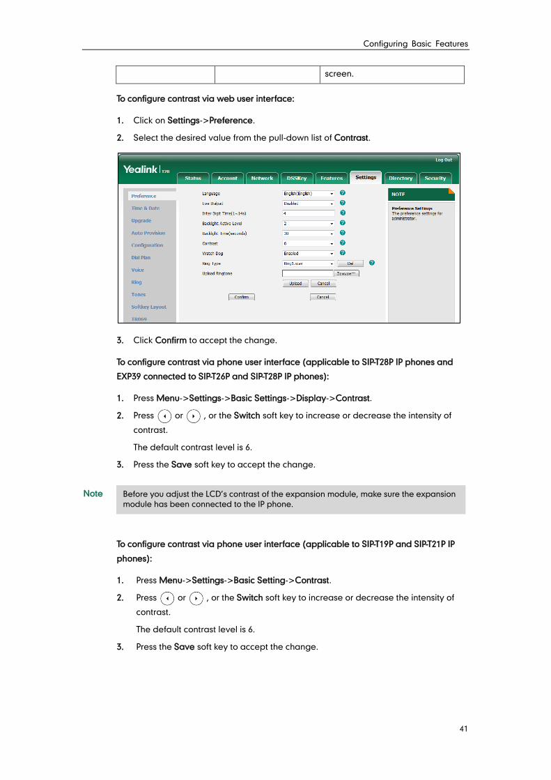
Configuring Basic Features
41
screen.
To configure contrast via web user interface:
1. Click on Settings->Preference.
2. Select the desired value from the pull-down list of Contrast.
3. Click Confirm to accept the change.
To configure contrast via phone user interface (applicable to SIP-T28P IP phones and
EXP39 connected to SIP-T26P and SIP-T28P IP phones):
1. Press Menu->Settings->Basic Settings->Display->Contrast.
2. Press or , or the Switch soft key to increase or decrease the intensity of
contrast.
The default contrast level is 6.
3. Press the Save soft key to accept the change.
Note
To configure contrast via phone user interface (applicable to SIP-T19P and SIP-T21P IP
phones):
1. Press Menu->Settings->Basic Setting->Contrast.
2. Press or , or the Switch soft key to increase or decrease the intensity of
contrast.
The default contrast level is 6.
3. Press the Save soft key to accept the change.
Before you adjust the LCD’s contrast of the expansion module, make sure the expansion
module has been connected to the IP phone.
Administrator’s Guide for SIP-T2xP and SIP-T19P IP Phones
42
Backlight determines the brightness of the LCD screen display, allowing users to read
easily in dark environments. Backlight time specifies the delay time to turn off the
backlight when the IP phone is inactive. Backlight time is only applicable to SIP-T22P,
SIP-T26P and SIP-T28P IP phones, and EXP39 connected to SIP-T26P and SIP-T28P IP phones.
Backlight turns off quickly if a short backlight time is configured, this may not give users
enough time to read messages. Backlight active level is used to adjust the backlight
intensity of the LCD screen. Backlight active level is only applicable to SIP-T28P IP phones
and the connected EXP39.
You can configure the backlight time as one of the following types:
Always Off: Backlight is turned off permanently.
Always On: Backlight is turned on permanently.
15, 30, 60, 120, 300, 600 or 1800: Backlight is turned off when the IP phone is inactive
after a preset period of time (in seconds), but it is automatically turned on if the
status of the IP phone changes or any key is pressed.
The following table lists available methods and configuration options to configure the
backlight of each phone model.
Phone Model Configuration Methods Configuration Options
SIP-T28P
Configuration Files
Web User Interface
Phone User Interface
Backlight Active Level
Backlight Time
SIP-T26P
Configuration Files
Web User Interface
Phone User Interface (only
applicable to the connected
EXP39)
Backlight Active Level (only
applicable to the connected
EXP39)
Backlight Time
SIP-T22P Configuration Files
Web User Interface Backlight Time
Procedure
Backlight can be configured using the configuration files or locally.
Configuration File <y0000000000xx>.cfg
Configure the backlight of the
LCD screen.
For more information, refer to
Backlight on page 286.
Local Web User Interface Configure the backlight of the
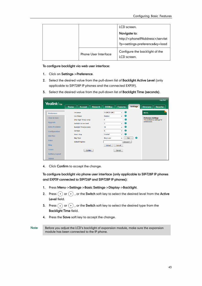
Configuring Basic Features
43
LCD screen.
Navigate to:
http://<phoneIPAddress>/servlet
?p=settings-preference&q=load
Phone User Interface Configure the backlight of the
LCD screen.
To configure backlight via web user interface:
1. Click on Settings->Preference.
2. Select the desired value from the pull-down list of Backlight Active Level (only
applicable to SIP-T28P IP phones and the connected EXP39).
3. Select the desired value from the pull-down list of Backlight Time (seconds).
4. Click Confirm to accept the change.
To configure backlight via phone user interface (only applicable to SIP-T28P IP phones
and EXP39 connected to SIP-T26P and SIP-T28P IP phones):
1. Press Menu->Settings->Basic Settings->Display->Backlight.
2. Press or , or the Switch soft key to select the desired level from the Active
Level field.
3. Press or , or the Switch soft key to select the desired type from the
Backlight Time field.
4. Press the Save soft key to accept the change.
Note Before you adjust the LCD’s backlight of expansion module, make sure the expansion
module has been connected to the IP phone.
Administrator’s Guide for SIP-T2xP and SIP-T19P IP Phones
44
Web server type determines access protocol of the IP phone’s web user interface. IP
phones support both HTTP and HTTPS protocols for accessing the web user interface.
HTTP is an application protocol that runs on top of the TCP/IP suite of protocols. HTTPS is
a web protocol that encrypts and decrypts user page requests as well as pages
returned by the web server. Both HTTP and HTTPS port numbers are configurable.
Procedure
Web server type can be configured using the configuration files or locally.
Configuration File <y0000000000xx>.cfg
Configure the web access type,
HTTP port and HTTPS port.
For more information, refer to
Web Server Type on page 287.
Local
Web User Interface
Configure the web access type,
HTTP port and HTTPS port.
Navigate to:
http://<phoneIPAddress>/servl
et?p=network-adv&q=load
Phone User Interface Configure the web access type,
HTTP port and HTTPS port.
To configure web server type via web user interface:
1. Click on Network->Advanced.
2. Select the desired value from the pull-down list of HTTP.
3. Enter the HTTP port number in the HTTP Port (1~65535) field.
The default HTTP port number is 80.
4. Select the desired value from the pull-down list of HTTPS.
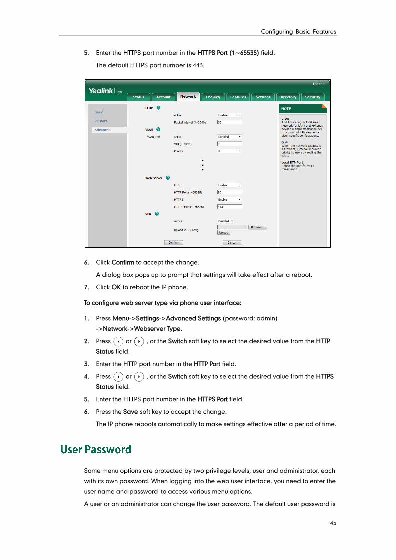
Configuring Basic Features
45
5. Enter the HTTPS port number in the HTTPS Port (1~65535) field.
The default HTTPS port number is 443.
6. Click Confirm to accept the change.
A dialog box pops up to prompt that settings will take effect after a reboot.
7. Click OK to reboot the IP phone.
To configure web server type via phone user interface:
1. Press Menu->Settings->Advanced Settings (password: admin)
->Network->Webserver Type.
2. Press or , or the Switch soft key to select the desired value from the HTTP
Status field.
3. Enter the HTTP port number in the HTTP Port field.
4. Press or , or the Switch soft key to select the desired value from the HTTPS
Status field.
5. Enter the HTTPS port number in the HTTPS Port field.
6. Press the Save soft key to accept the change.
The IP phone reboots automatically to make settings effective after a period of time.
Some menu options are protected by two privilege levels, user and administrator, each
with its own password. When logging into the web user interface, you need to enter the
user name and password to access various menu options.
A user or an administrator can change the user password. The default user password is
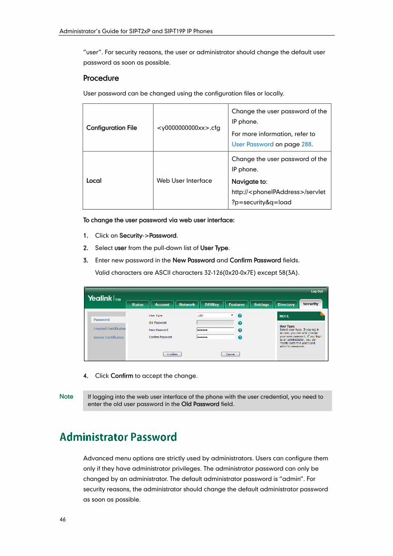
Administrator’s Guide for SIP-T2xP and SIP-T19P IP Phones
46
“user”. For security reasons, the user or administrator should change the default user
password as soon as possible.
Procedure
User password can be changed using the configuration files or locally.
Configuration File <y0000000000xx>.cfg
Change the user password of the
IP phone.
For more information, refer to
User Password on page 288.
Local Web User Interface
Change the user password of the
IP phone.
Navigate to:
http://<phoneIPAddress>/servlet
?p=security&q=load
To change the user password via web user interface:
1. Click on Security->Password.
2. Select user from the pull-down list of User Type.
3. Enter new password in the New Password and Confirm Password fields.
Valid characters are ASCII characters 32-126(0x20-0x7E) except 58(3A).
4. Click Confirm to accept the change.
Note
Advanced menu options are strictly used by administrators. Users can configure them
only if they have administrator privileges. The administrator password can only be
changed by an administrator. The default administrator password is “admin”. For
security reasons, the administrator should change the default administrator password
as soon as possible.
If logging into the web user interface of the phone with the user credential, you need to
enter the old user password in the Old Password field.
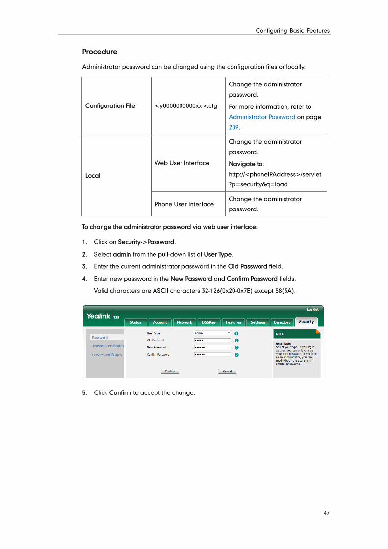
Configuring Basic Features
47
Procedure
Administrator password can be changed using the configuration files or locally.
Configuration File <y0000000000xx>.cfg
Change the administrator
password.
For more information, refer to
Administrator Password on page
289.
Local
Web User Interface
Change the administrator
password.
Navigate to:
http://<phoneIPAddress>/servlet
?p=security&q=load
Phone User Interface Change the administrator
password.
To change the administrator password via web user interface:
1. Click on Security->Password.
2. Select admin from the pull-down list of User Type.
3. Enter the current administrator password in the Old Password field.
4. Enter new password in the New Password and Confirm Password fields.
Valid characters are ASCII characters 32-126(0x20-0x7E) except 58(3A).
5. Click Confirm to accept the change.
Administrator’s Guide for SIP-T2xP and SIP-T19P IP Phones
48
To change the administrator password via phone user interface:
1. Press Menu->Settings->Advanced Settings (password: admin) ->Set Password.
2. Enter the current administrator password in the Current PWD field.
3. Enter new password in the New PWD field and Confirm PWD field.
Valid characters are ASCII characters 32-126(0x20-0x7E).
4. Press the Save soft key to accept the change.
Phone lock is used to lock the IP phone to prevent it from unauthorized use. Once the
IP phone is locked, a user must enter the password to unlock it. IP phones offer three
types of phone lock: Menu Key, Function Keys and All Keys. The IP phone will not be
locked immediately after the phone lock type is configured. One of the following
steps is also needed:
- Long press the pound key when the IP phone is idle.
- Press the keypad lock key (if configured) when the IP phone is idle.
In addition to the above steps, you can configure the IP phone to automatically lock
the keypad after a period of time.
Procedure
Phone lock can be configured using the configuration files or locally.
Configuration File <y0000000000xx>.cfg
Configure the type of phone
lock.
Change the unlock PIN.
Configure the IP phone to
automatically lock the keypad
after a time interval.
For more information, refer to
Phone Lock on page 289.
Assign a keypad lock key.
For more information, refer to
Keypad Lock Key on page 419.
Local Web User Interface
Configure the type of phone
lock.
Change the unlock PIN.
Configure the IP phone to
automatically lock the keypad
after a time interval.
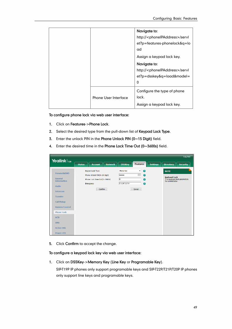
Configuring Basic Features
49
Navigate to:
http://<phoneIPAddress>/servl
et?p=features-phonelock&q=lo
ad
Assign a keypad lock key.
Navigate to:
http://<phoneIPAddress>/servl
et?p=dsskey&q=load&model=
0
Phone User Interface
Configure the type of phone
lock.
Assign a keypad lock key.
To configure phone lock via web user interface:
1. Click on Features->Phone Lock.
2. Select the desired type from the pull-down list of Keypad Lock Type.
3. Enter the unlock PIN in the Phone Unlock PIN (0~15 Digit) field.
4. Enter the desired time in the Phone Lock Time Out (0~3600s) field.
5. Click Confirm to accept the change.
To configure a keypad lock key via web user interface:
1. Click on DSSKey->Memory Key (Line Key or Programable Key).
SIP-T19P IP phones only support programable keys and SIP-T22P/T21P/T20P IP phones
only support line keys and programable keys.
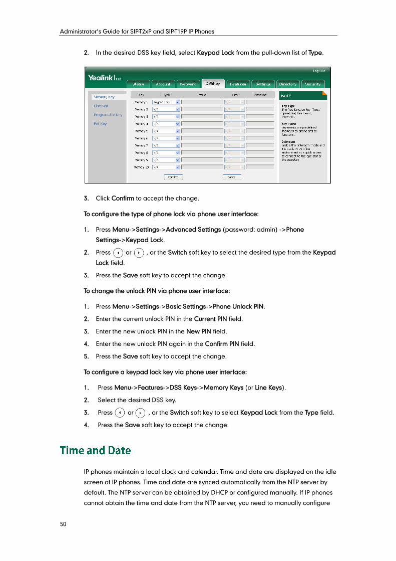
Administrator’s Guide for SIP-T2xP and SIP-T19P IP Phones
50
2. In the desired DSS key field, select Keypad Lock from the pull-down list of Type.
3. Click Confirm to accept the change.
To configure the type of phone lock via phone user interface:
1. Press Menu->Settings->Advanced Settings (password: admin) ->Phone
Settings->Keypad Lock.
2. Press or , or the Switch soft key to select the desired type from the Keypad
Lock field.
3. Press the Save soft key to accept the change.
To change the unlock PIN via phone user interface:
1. Press Menu->Settings->Basic Settings->Phone Unlock PIN.
2. Enter the current unlock PIN in the Current PIN field.
3. Enter the new unlock PIN in the New PIN field.
4. Enter the new unlock PIN again in the Confirm PIN field.
5. Press the Save soft key to accept the change.
To configure a keypad lock key via phone user interface:
1. Press Menu->Features->DSS Keys->Memory Keys (or Line Keys).
2. Select the desired DSS key.
3. Press or , or the Switch soft key to select Keypad Lock from the Type field.
4. Press the Save soft key to accept the change.
IP phones maintain a local clock and calendar. Time and date are displayed on the idle
screen of IP phones. Time and date are synced automatically from the NTP server by
default. The NTP server can be obtained by DHCP or configured manually. If IP phones
cannot obtain the time and date from the NTP server, you need to manually configure
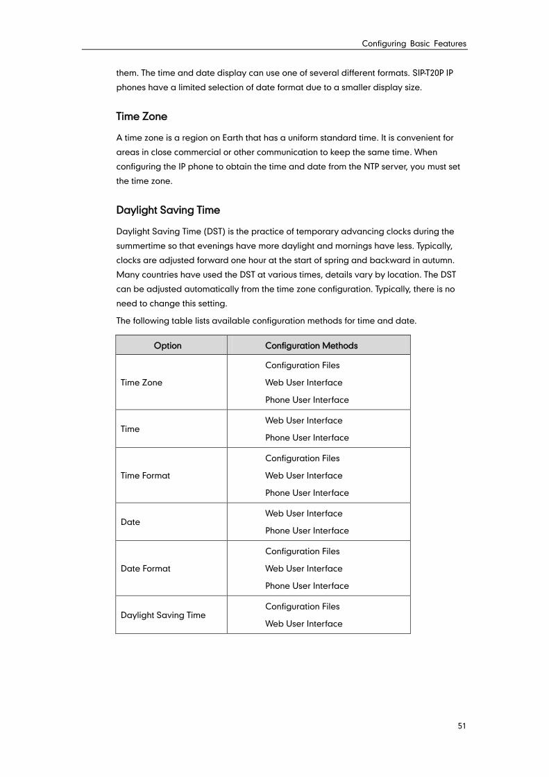
Configuring Basic Features
51
them. The time and date display can use one of several different formats. SIP-T20P IP
phones have a limited selection of date format due to a smaller display size.
Time Zone
A time zone is a region on Earth that has a uniform standard time. It is convenient for
areas in close commercial or other communication to keep the same time. When
configuring the IP phone to obtain the time and date from the NTP server, you must set
the time zone.
Daylight Saving Time
Daylight Saving Time (DST) is the practice of temporary advancing clocks during the
summertime so that evenings have more daylight and mornings have less. Typically,
clocks are adjusted forward one hour at the start of spring and backward in autumn.
Many countries have used the DST at various times, details vary by location. The DST
can be adjusted automatically from the time zone configuration. Typically, there is no
need to change this setting.
The following table lists available configuration methods for time and date.
Option Configuration Methods
Time Zone
Configuration Files
Web User Interface
Phone User Interface
Time Web User Interface
Phone User Interface
Time Format
Configuration Files
Web User Interface
Phone User Interface
Date Web User Interface
Phone User Interface
Date Format
Configuration Files
Web User Interface
Phone User Interface
Daylight Saving Time Configuration Files
Web User Interface
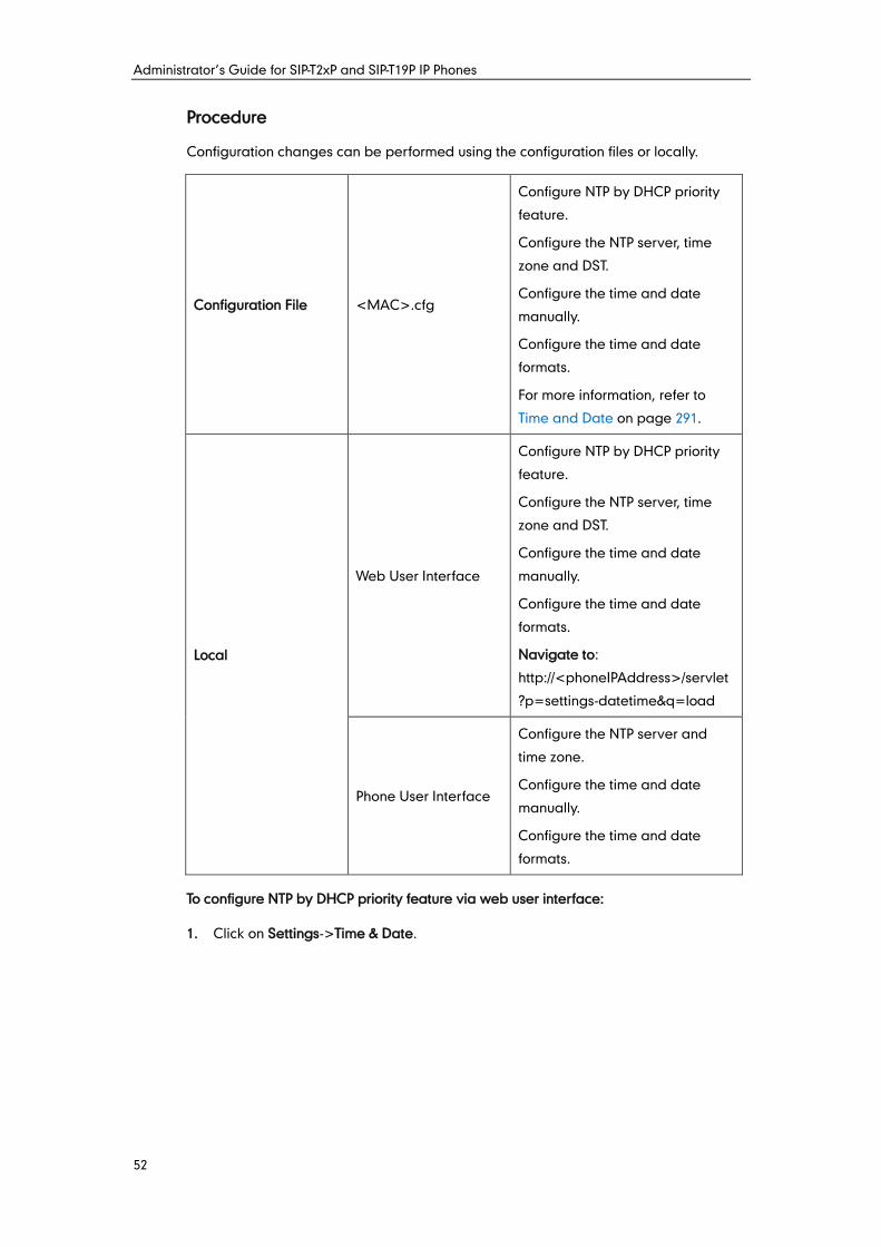
Administrator’s Guide for SIP-T2xP and SIP-T19P IP Phones
52
Procedure
Configuration changes can be performed using the configuration files or locally.
Configuration File <MAC>.cfg
Configure NTP by DHCP priority
feature.
Configure the NTP server, time
zone and DST.
Configure the time and date
manually.
Configure the time and date
formats.
For more information, refer to
Time and Date on page 291.
Local
Web User Interface
Configure NTP by DHCP priority
feature.
Configure the NTP server, time
zone and DST.
Configure the time and date
manually.
Configure the time and date
formats.
Navigate to:
http://<phoneIPAddress>/servlet
?p=settings-datetime&q=load
Phone User Interface
Configure the NTP server and
time zone.
Configure the time and date
manually.
Configure the time and date
formats.
To configure NTP by DHCP priority feature via web user interface:
1. Click on Settings->Time & Date.
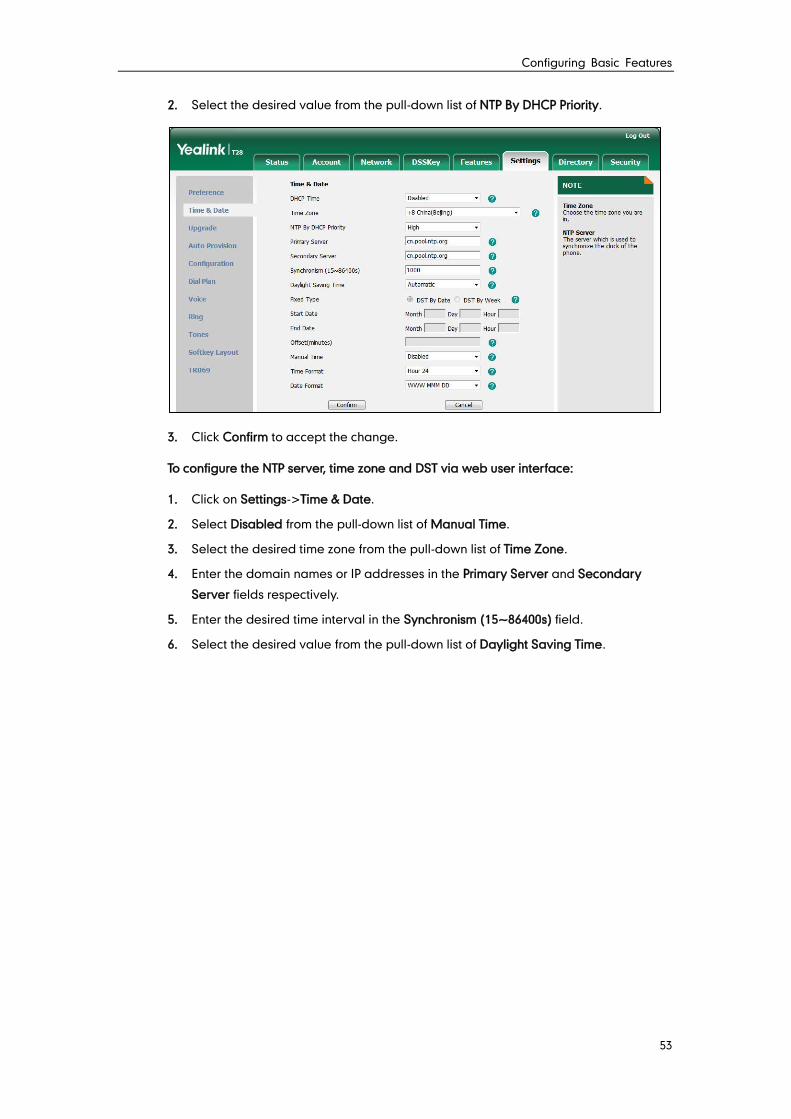
Configuring Basic Features
53
2. Select the desired value from the pull-down list of NTP By DHCP Priority.
3. Click Confirm to accept the change.
To configure the NTP server, time zone and DST via web user interface:
1. Click on Settings->Time & Date.
2. Select Disabled from the pull-down list of Manual Time.
3. Select the desired time zone from the pull-down list of Time Zone.
4. Enter the domain names or IP addresses in the Primary Server and Secondary
Server fields respectively.
5. Enter the desired time interval in the Synchronism (15~86400s) field.
6. Select the desired value from the pull-down list of Daylight Saving Time.
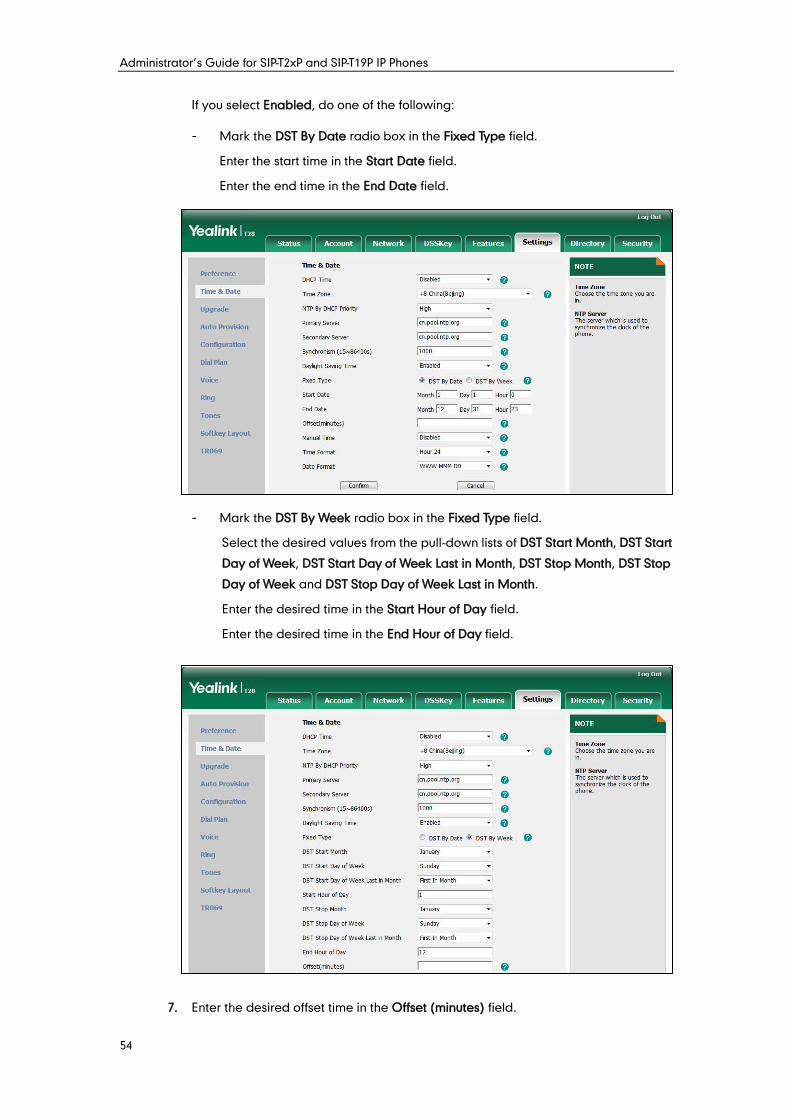
Administrator’s Guide for SIP-T2xP and SIP-T19P IP Phones
54
If you select Enabled, do one of the following:
- Mark the DST By Date radio box in the Fixed Type field.
Enter the start time in the Start Date field.
Enter the end time in the End Date field.
- Mark the DST By Week radio box in the Fixed Type field.
Select the desired values from the pull-down lists of DST Start Month, DST Start
Day of Week, DST Start Day of Week Last in Month, DST Stop Month, DST Stop
Day of Week and DST Stop Day of Week Last in Month.
Enter the desired time in the Start Hour of Day field.
Enter the desired time in the End Hour of Day field.
7. Enter the desired offset time in the Offset (minutes) field.
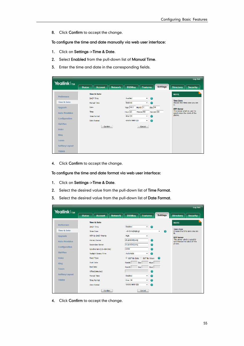
Configuring Basic Features
55
8. Click Confirm to accept the change.
To configure the time and date manually via web user interface:
1. Click on Settings->Time & Date.
2. Select Enabled from the pull-down list of Manual Time.
3. Enter the time and date in the corresponding fields.
4. Click Confirm to accept the change.
To configure the time and date format via web user interface:
1. Click on Settings->Time & Date.
2. Select the desired value from the pull-down list of Time Format.
3. Select the desired value from the pull-down list of Date Format.
4. Click Confirm to accept the change.
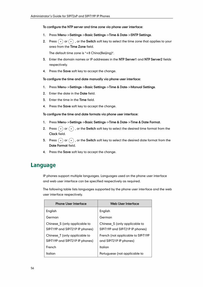
Administrator’s Guide for SIP-T2xP and SIP-T19P IP Phones
56
To configure the NTP server and time zone via phone user interface:
1. Press Menu->Settings->Basic Settings->Time & Date->SNTP Settings.
2. Press or , or the Switch soft key to select the time zone that applies to your
area from the Time Zone field.
The default time zone is "+8 China(Beijing)".
3. Enter the domain names or IP addresses in the NTP Server1 and NTP Server2 fields
respectively.
4. Press the Save soft key to accept the change.
To configure the time and date manually via phone user interface:
1. Press Menu->Settings->Basic Settings->Time & Date->Manual Settings.
2. Enter the date in the Date field.
3. Enter the time in the Time field.
4. Press the Save soft key to accept the change.
To configure the time and date formats via phone user interface:
1. Press Menu->Settings->Basic Settings->Time & Date->Time & Date Format.
2. Press or , or the Switch soft key to select the desired time format from the
Clock field.
3. Press or , or the Switch soft key to select the desired date format from the
Date Format field.
4. Press the Save soft key to accept the change.
IP phones support multiple languages. Languages used on the phone user interface
and web user interface can be specified respectively as required.
The following table lists languages supported by the phone user interface and the web
user interface respectively.
Phone User Interface Web User Interface
English
German
Chinese_S (only applicable to
SIP-T19P and SIP-T21P IP phones)
Chinese_T (only applicable to
SIP-T19P and SIP-T21P IP phones)
French
Italian
English
German
Chinese_S (only applicable to
SIP-T19P and SIP-T21P IP phones)
French (not applicable to SIP-T19P
and SIP-T21P IP phones)
Italian
Portuguese (not applicable to
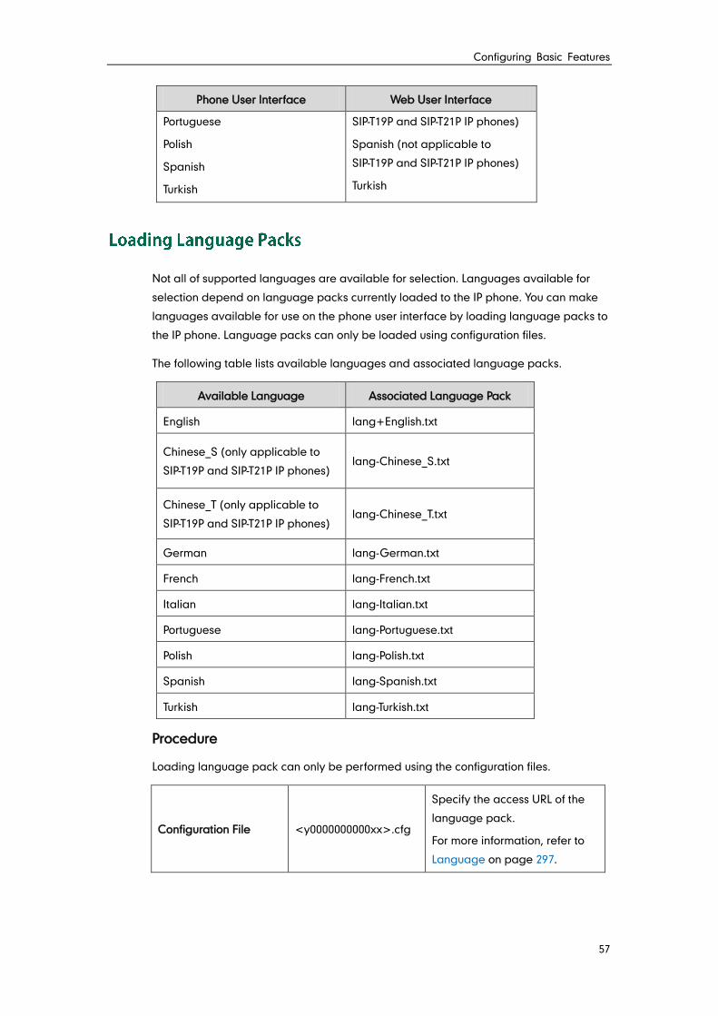
Configuring Basic Features
57
Phone User Interface Web User Interface
Portuguese
Polish
Spanish
Turkish
SIP-T19P and SIP-T21P IP phones)
Spanish (not applicable to
SIP-T19P and SIP-T21P IP phones)
Turkish
Not all of supported languages are available for selection. Languages available for
selection depend on language packs currently loaded to the IP phone. You can make
languages available for use on the phone user interface by loading language packs to
the IP phone. Language packs can only be loaded using configuration files.
The following table lists available languages and associated language packs.
Available Language Associated Language Pack
English lang+English.txt
Chinese_S (only applicable to
SIP-T19P and SIP-T21P IP phones) lang-Chinese_S.txt
Chinese_T (only applicable to
SIP-T19P and SIP-T21P IP phones) lang-Chinese_T.txt
German lang-German.txt
French lang-French.txt
Italian lang-Italian.txt
Portuguese lang-Portuguese.txt
Polish lang-Polish.txt
Spanish lang-Spanish.txt
Turkish lang-Turkish.txt
Procedure
Loading language pack can only be performed using the configuration files.
Configuration File <y0000000000xx>.cfg
Specify the access URL of the
language pack.
For more information, refer to
Language on page 297.
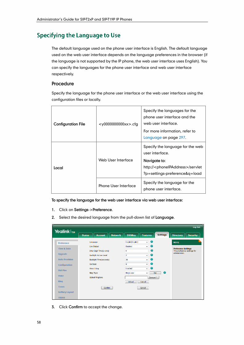
Administrator’s Guide for SIP-T2xP and SIP-T19P IP Phones
58
The default language used on the phone user interface is English. The default language
used on the web user interface depends on the language preferences in the browser (if
the language is not supported by the IP phone, the web user interface uses English). You
can specify the languages for the phone user interface and web user interface
respectively.
Procedure
Specify the language for the phone user interface or the web user interface using the
configuration files or locally.
Configuration File <y0000000000xx>.cfg
Specify the languages for the
phone user interface and the
web user interface.
For more information, refer to
Language on page 297.
Local
Web User Interface
Specify the language for the web
user interface.
Navigate to:
http://<phoneIPAddress>/servlet
?p=settings-preference&q=load
Phone User Interface Specify the language for the
phone user interface.
To specify the language for the web user interface via web user interface:
1. Click on Settings->Preference.
2. Select the desired language from the pull-down list of Language.
3. Click Confirm to accept the change.
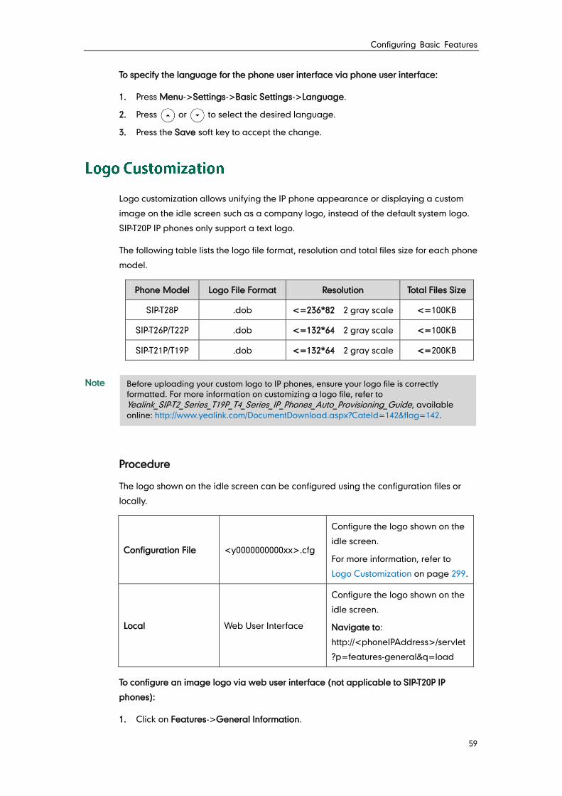
Configuring Basic Features
59
To specify the language for the phone user interface via phone user interface:
1. Press Menu->Settings->Basic Settings->Language.
2. Press or to select the desired language.
3. Press the Save soft key to accept the change.
Logo customization allows unifying the IP phone appearance or displaying a custom
image on the idle screen such as a company logo, instead of the default system logo.
SIP-T20P IP phones only support a text logo.
The following table lists the logo file format, resolution and total files size for each phone
model.
Phone Model Logo File Format Resolution Total Files Size
SIP-T28P .dob <=236*82 2 gray scale <=100KB
SIP-T26P/T22P .dob <=132*64 2 gray scale <=100KB
SIP-T21P/T19P .dob <=132*64 2 gray scale <=200KB
Note
Procedure
The logo shown on the idle screen can be configured using the configuration files or
locally.
Configuration File <y0000000000xx>.cfg
Configure the logo shown on the
idle screen.
For more information, refer to
Logo Customization on page 299.
Local Web User Interface
Configure the logo shown on the
idle screen.
Navigate to:
http://<phoneIPAddress>/servlet
?p=features-general&q=load
To configure an image logo via web user interface (not applicable to SIP-T20P IP
phones):
1. Click on Features->General Information.
Before uploading your custom logo to IP phones, ensure your logo file is correctly
formatted. For more information on customizing a logo file, refer to
Yealink_SIP-T2_Series_T19P_T4_Series_IP_Phones_Auto_Provisioning_Guide, available
online: http://www.yealink.com/DocumentDownload.aspx?CateId=142&flag=142.

Administrator’s Guide for SIP-T2xP and SIP-T19P IP Phones
60
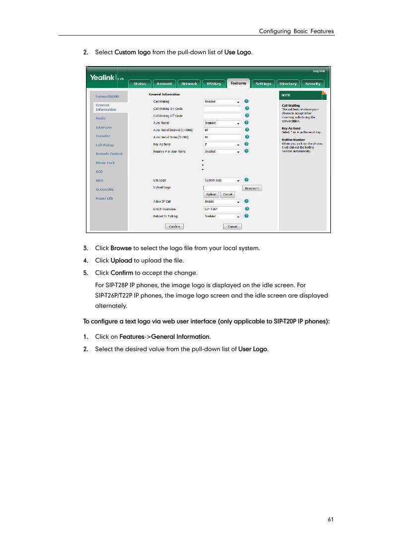
Configuring Basic Features
61
2. Select Custom logo from the pull-down list of Use Logo.
3. Click Browse to select the logo file from your local system.
4. Click Upload to upload the file.
5. Click Confirm to accept the change.
For SIP-T28P IP phones, the image logo is displayed on the idle screen. For
SIP-T26P/T22P IP phones, the image logo screen and the idle screen are displayed
alternately.
To configure a text logo via web user interface (only applicable to SIP-T20P IP phones):
1. Click on Features->General Information.
2. Select the desired value from the pull-down list of User Logo.
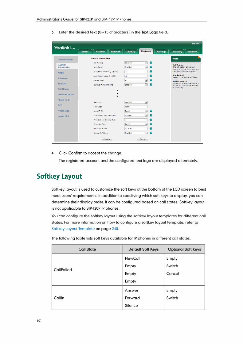
Administrator’s Guide for SIP-T2xP and SIP-T19P IP Phones
62
3. Enter the desired text (0~15 characters) in the Text Logo field.
4. Click Confirm to accept the change.
The registered account and the configured text logo are displayed alternately.
Softkey layout is used to customize the soft keys at the bottom of the LCD screen to best
meet users’ requirements. In addition to specifying which soft keys to display, you can
determine their display order. It can be configured based on call states. Softkey layout
is not applicable to SIP-T20P IP phones.
You can configure the softkey layout using the softkey layout templates for different call
states. For more information on how to configure a softkey layout template, refer to
Softkey Layout Template on page 240.
The following table lists soft keys available for IP phones in different call states.
Call State Default Soft Keys Optional Soft Keys
CallFailed
NewCall
Empty
Empty
Empty
Empty
Switch
Cancel
CallIn
Answer
Forward
Silence
Empty
Switch
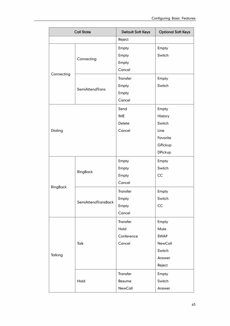
Configuring Basic Features
63
Call State Default Soft Keys Optional Soft Keys
Reject
Connecting
Connecting
Empty
Empty
Empty
Cancel
Empty
Switch
SemiAttendTrans
Transfer
Empty
Empty
Cancel
Empty
Switch
Dialing
Send
IME
Delete
Cancel
Empty
History
Switch
Line
Favorite
GPickup
DPickup
RingBack
RingBack
Empty
Empty
Empty
Cancel
Empty
Switch
CC
SemiAttendTransBack
Transfer
Empty
Empty
Cancel
Empty
Switch
CC
Talking
Talk
Transfer
Hold
Conference
Cancel
Empty
Mute
SWAP
NewCall
Switch
Answer
Reject
Hold
Transfer
Resume
NewCall
Empty
Switch
Answer
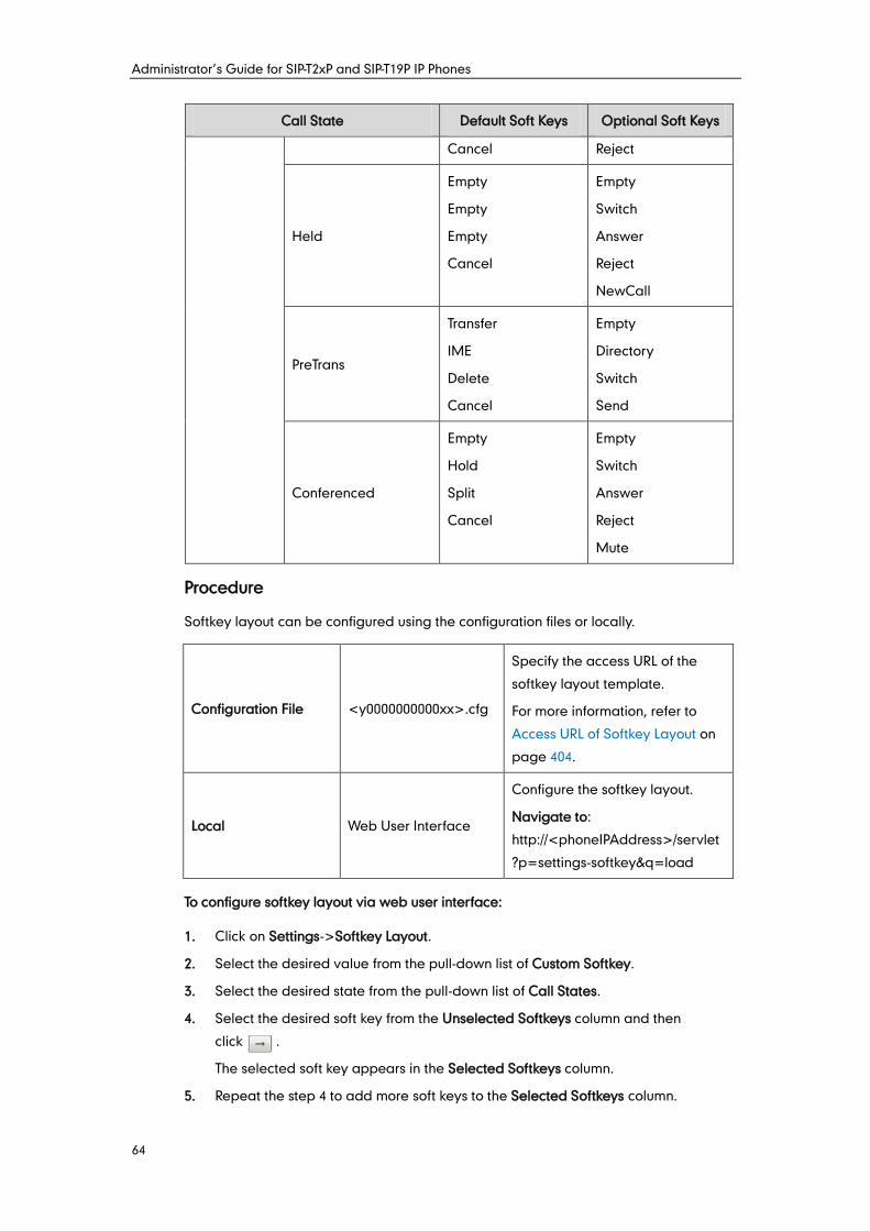
Administrator’s Guide for SIP-T2xP and SIP-T19P IP Phones
64
Call State Default Soft Keys Optional Soft Keys
Cancel Reject
Held
Empty
Empty
Empty
Cancel
Empty
Switch
Answer
Reject
NewCall
PreTrans
Transfer
IME
Delete
Cancel
Empty
Directory
Switch
Send
Conferenced
Empty
Hold
Split
Cancel
Empty
Switch
Answer
Reject
Mute
Procedure
Softkey layout can be configured using the configuration files or locally.
Configuration File <y0000000000xx>.cfg
Specify the access URL of the
softkey layout template.
For more information, refer to
Access URL of Softkey Layout on
page 404.
Local Web User Interface
Configure the softkey layout.
Navigate to:
http://<phoneIPAddress>/servlet
?p=settings-softkey&q=load
To configure softkey layout via web user interface:
1. Click on Settings->Softkey Layout.
2. Select the desired value from the pull-down list of Custom Softkey.
3. Select the desired state from the pull-down list of Call States.
4. Select the desired soft key from the Unselected Softkeys column and then
click .
The selected soft key appears in the Selected Softkeys column.
5. Repeat the step 4 to add more soft keys to the Selected Softkeys column.
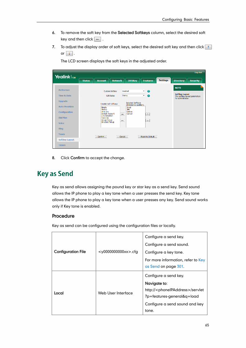
Configuring Basic Features
65
6. To remove the soft key from the Selected Softkeys column, select the desired soft
key and then click .
7. To adjust the display order of soft keys, select the desired soft key and then click
or .
The LCD screen displays the soft keys in the adjusted order.
8. Click Confirm to accept the change.
Key as send allows assigning the pound key or star key as a send key. Send sound
allows the IP phone to play a key tone when a user presses the send key. Key tone
allows the IP phone to play a key tone when a user presses any key. Send sound works
only if Key tone is enabled.
Procedure
Key as send can be configured using the configuration files or locally.
Configuration File <y0000000000xx>.cfg
Configure a send key.
Configure a send sound.
Configure a key tone.
For more information, refer to Key
as Send on page 301.
Local Web User Interface
Configure a send key.
Navigate to:
http://<phoneIPAddress>/servlet
?p=features-general&q=load
Configure a send sound and key
tone.
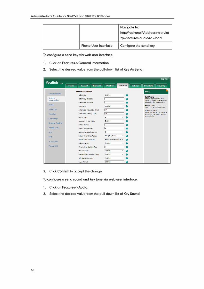
Administrator’s Guide for SIP-T2xP and SIP-T19P IP Phones
66
Navigate to:
http://<phoneIPAddress>/servlet
?p=features-audio&q=load
Phone User Interface Configure the send key.
To configure a send key via web user interface:
1. Click on Features->General Information.
2. Select the desired value from the pull-down list of Key As Send.
3. Click Confirm to accept the change.
To configure a send sound and key tone via web user interface:
1. Click on Features->Audio.
2. Select the desired value from the pull-down list of Key Sound.
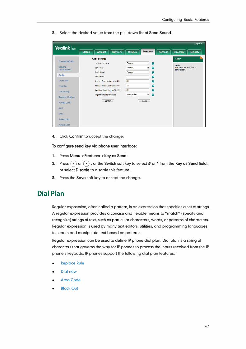
Configuring Basic Features
67
3. Select the desired value from the pull-down list of Send Sound.
4. Click Confirm to accept the change.
To configure send key via phone user interface:
1. Press Menu->Features->Key as Send.
2. Press or , or the Switch soft key to select # or * from the Key as Send field,
or select Disable to disable this feature.
3. Press the Save soft key to accept the change.
Regular expression, often called a pattern, is an expression that specifies a set of strings.
A regular expression provides a concise and flexible means to “match” (specify and
recognize) strings of text, such as particular characters, words, or patterns of characters.
Regular expression is used by many text editors, utilities, and programming languages
to search and manipulate text based on patterns.
Regular expression can be used to define IP phone dial plan. Dial plan is a string of
characters that governs the way for IP phones to process the inputs received from the IP
phone’s keypads. IP phones support the following dial plan features:
Replace Rule
Dial-now
Area Code
Block Out
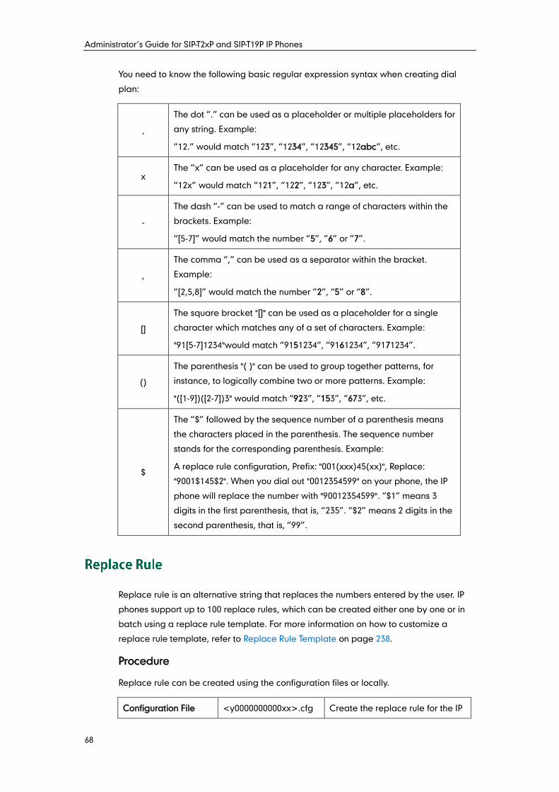
Administrator’s Guide for SIP-T2xP and SIP-T19P IP Phones
68
You need to know the following basic regular expression syntax when creating dial
plan:
.
The dot “.” can be used as a placeholder or multiple placeholders for
any string. Example:
“12.” would match “123”, “1234”, “12345”, “12abc”, etc.
x The “x” can be used as a placeholder for any character. Example:
“12x” would match “121”, “122”, “123”, “12a”, etc.
-
The dash “-” can be used to match a range of characters within the
brackets. Example:
“[5-7]” would match the number “5”, ”6” or ”7”.
,
The comma “,” can be used as a separator within the bracket.
Example:
“[2,5,8]” would match the number ”2”, “5” or “8”.
[]
The square bracket "[]" can be used as a placeholder for a single
character which matches any of a set of characters. Example:
"91[5-7]1234"would match “9151234”, “9161234”, “9171234”.
()
The parenthesis "( )" can be used to group together patterns, for
instance, to logically combine two or more patterns. Example:
"([1-9])([2-7])3" would match “923”, “153”, “673”, etc.
$
The “$” followed by the sequence number of a parenthesis means
the characters placed in the parenthesis. The sequence number
stands for the corresponding parenthesis. Example:
A replace rule configuration, Prefix: "001(xxx)45(xx)", Replace:
"9001$145$2". When you dial out "0012354599" on your phone, the IP
phone will replace the number with "90012354599". “$1” means 3
digits in the first parenthesis, that is, “235”. “$2” means 2 digits in the
second parenthesis, that is, “99”.
Replace rule is an alternative string that replaces the numbers entered by the user. IP
phones support up to 100 replace rules, which can be created either one by one or in
batch using a replace rule template. For more information on how to customize a
replace rule template, refer to Replace Rule Template on page 238.
Procedure
Replace rule can be created using the configuration files or locally.
Configuration File <y0000000000xx>.cfg Create the replace rule for the IP
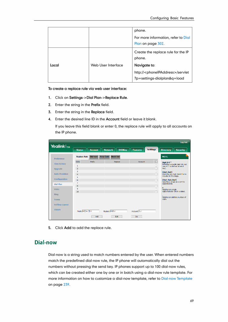
Configuring Basic Features
69
phone.
For more information, refer to Dial
Plan on page 302.
Local Web User Interface
Create the replace rule for the IP
phone.
Navigate to:
http://<phoneIPAddress>/servlet
?p=settings-dialplan&q=load
To create a replace rule via web user interface:
1. Click on Settings->Dial Plan->Replace Rule.
2. Enter the string in the Prefix field.
3. Enter the string in the Replace field.
4. Enter the desired line ID in the Account field or leave it blank.
If you leave this field blank or enter 0, the replace rule will apply to all accounts on
the IP phone.
5. Click Add to add the replace rule.
Dial-now is a string used to match numbers entered by the user. When entered numbers
match the predefined dial-now rule, the IP phone will automatically dial out the
numbers without pressing the send key. IP phones support up to 100 dial-now rules,
which can be created either one by one or in batch using a dial-now rule template. For
more information on how to customize a dial-now template, refer to Dial-now Template
on page 239.
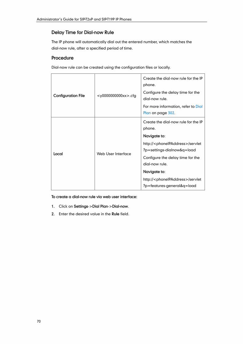
Administrator’s Guide for SIP-T2xP and SIP-T19P IP Phones
70
Delay Time for Dial-now Rule
The IP phone will automatically dial out the entered number, which matches the
dial-now rule, after a specified period of time.
Procedure
Dial-now rule can be created using the configuration files or locally.
Configuration File <y0000000000xx>.cfg
Create the dial-now rule for the IP
phone.
Configure the delay time for the
dial-now rule.
For more information, refer to Dial
Plan on page 302.
Local Web User Interface
Create the dial-now rule for the IP
phone.
Navigate to:
http://<phoneIPAddress>/servlet
?p=settings-dialnow&q=load
Configure the delay time for the
dial-now rule.
Navigate to:
http://<phoneIPAddress>/servlet
?p=features-general&q=load
To create a dial-now rule via web user interface:
1. Click on Settings->Dial Plan->Dial-now.
2. Enter the desired value in the Rule field.
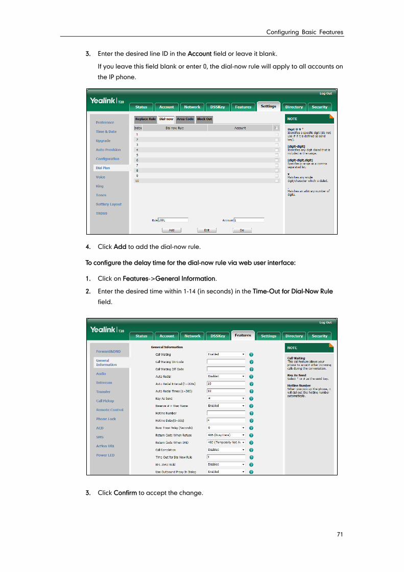
Configuring Basic Features
71
3. Enter the desired line ID in the Account field or leave it blank.
If you leave this field blank or enter 0, the dial-now rule will apply to all accounts on
the IP phone.
4. Click Add to add the dial-now rule.
To configure the delay time for the dial-now rule via web user interface:
1. Click on Features->General Information.
2. Enter the desired time within 1-14 (in seconds) in the Time-Out for Dial-Now Rule
field.
3. Click Confirm to accept the change.
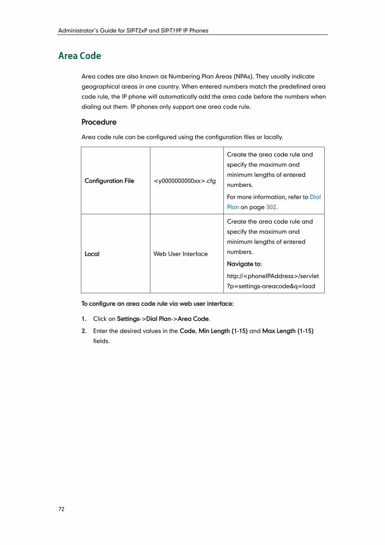
Administrator’s Guide for SIP-T2xP and SIP-T19P IP Phones
72
Area codes are also known as Numbering Plan Areas (NPAs). They usually indicate
geographical areas in one country. When entered numbers match the predefined area
code rule, the IP phone will automatically add the area code before the numbers when
dialing out them. IP phones only support one area code rule.
Procedure
Area code rule can be configured using the configuration files or locally.
Configuration File <y0000000000xx>.cfg
Create the area code rule and
specify the maximum and
minimum lengths of entered
numbers.
For more information, refer to Dial
Plan on page 302.
Local Web User Interface
Create the area code rule and
specify the maximum and
minimum lengths of entered
numbers.
Navigate to:
http://<phoneIPAddress>/servlet
?p=settings-areacode&q=load
To configure an area code rule via web user interface:
1. Click on Settings->Dial Plan->Area Code.
2. Enter the desired values in the Code, Min Length (1-15) and Max Length (1-15)
fields.
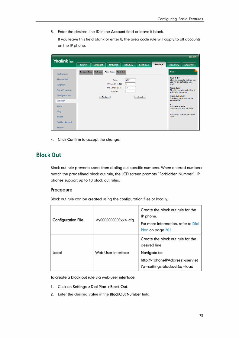
Configuring Basic Features
73
3. Enter the desired line ID in the Account field or leave it blank.
If you leave this field blank or enter 0, the area code rule will apply to all accounts
on the IP phone.
4. Click Confirm to accept the change.
Block out rule prevents users from dialing out specific numbers. When entered numbers
match the predefined block out rule, the LCD screen prompts “Forbidden Number”. IP
phones support up to 10 block out rules.
Procedure
Block out rule can be created using the configuration files or locally.
Configuration File <y0000000000xx>.cfg
Create the block out rule for the
IP phone.
For more information, refer to Dial
Plan on page 302.
Local Web User Interface
Create the block out rule for the
desired line.
Navigate to:
http://<phoneIPAddress>/servlet
?p=settings-blackout&q=load
To create a block out rule via web user interface:
1. Click on Settings->Dial Plan->Block Out.
2. Enter the desired value in the BlockOut Number field.
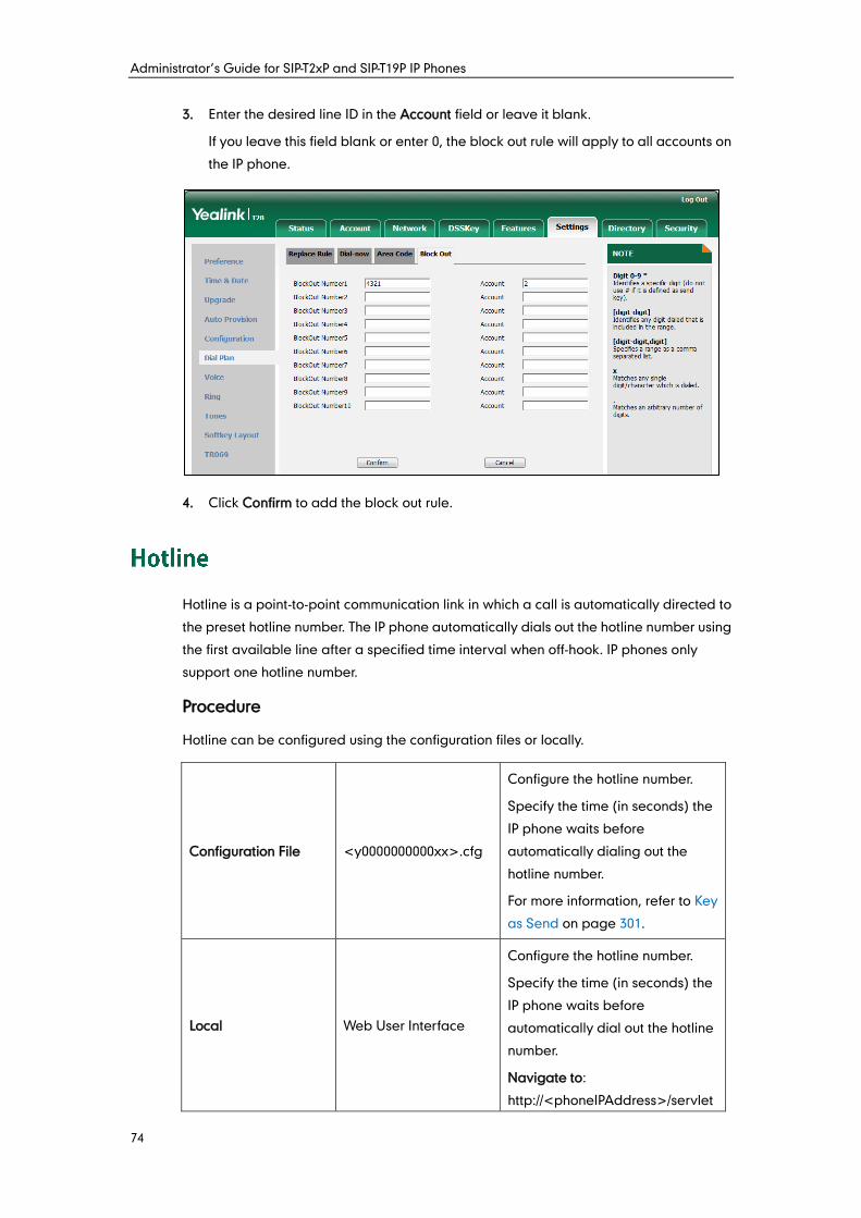
Administrator’s Guide for SIP-T2xP and SIP-T19P IP Phones
74
3. Enter the desired line ID in the Account field or leave it blank.
If you leave this field blank or enter 0, the block out rule will apply to all accounts on
the IP phone.
4. Click Confirm to add the block out rule.
Hotline is a point-to-point communication link in which a call is automatically directed to
the preset hotline number. The IP phone automatically dials out the hotline number using
the first available line after a specified time interval when off-hook. IP phones only
support one hotline number.
Procedure
Hotline can be configured using the configuration files or locally.
Configuration File <y0000000000xx>.cfg
Configure the hotline number.
Specify the time (in seconds) the
IP phone waits before
automatically dialing out the
hotline number.
For more information, refer to Key
as Send on page 301.
Local Web User Interface
Configure the hotline number.
Specify the time (in seconds) the
IP phone waits before
automatically dial out the hotline
number.
Navigate to:
http://<phoneIPAddress>/servlet
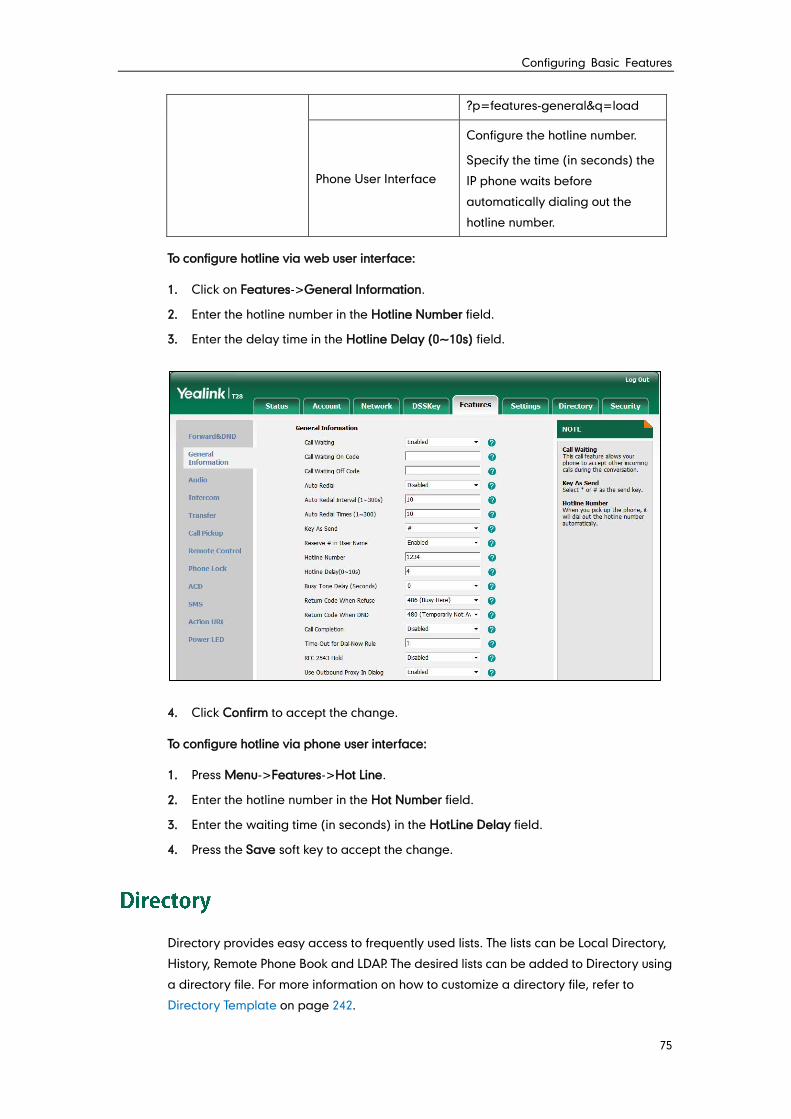
Configuring Basic Features
75
?p=features-general&q=load
Phone User Interface
Configure the hotline number.
Specify the time (in seconds) the
IP phone waits before
automatically dialing out the
hotline number.
To configure hotline via web user interface:
1. Click on Features->General Information.
2. Enter the hotline number in the Hotline Number field.
3. Enter the delay time in the Hotline Delay (0~10s) field.
4. Click Confirm to accept the change.
To configure hotline via phone user interface:
1. Press Menu->Features->Hot Line.
2. Enter the hotline number in the Hot Number field.
3. Enter the waiting time (in seconds) in the HotLine Delay field.
4. Press the Save soft key to accept the change.
Directory provides easy access to frequently used lists. The lists can be Local Directory,
History, Remote Phone Book and LDAP. The desired lists can be added to Directory using
a directory file. For more information on how to customize a directory file, refer to
Directory Template on page 242.
Administrator’s Guide for SIP-T2xP and SIP-T19P IP Phones
76
Procedure
Directory can be configured using the configuration files or locally.
Configuration File <y0000000000xx>.cfg
Specify the access URL of the
Directory file.
For more information, refer to
Access URL of Directory Template
on page 407.
Local Web User Interface
Configure the Directory.
Navigate to:
http://<phoneIPAddress>/servlet
?p=contacts-favorite&q=load
To configure the directory via web user interface:
1. Click on Directory->Setting.
2. In the Directory block, select the desired list from the Disabled column and then
click .
The selected list appears in the Enabled column.
3. Repeat step 2 to add more lists to the Enabled column.
4. To remove a list from the Enabled column, select the desired list and then click .
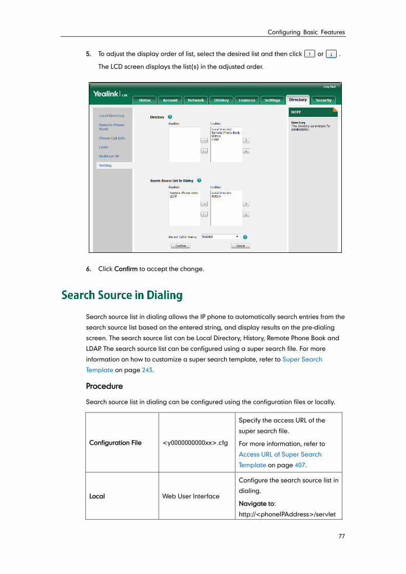
Configuring Basic Features
77
5. To adjust the display order of list, select the desired list and then click or .
The LCD screen displays the list(s) in the adjusted order.
6. Click Confirm to accept the change.
Search source list in dialing allows the IP phone to automatically search entries from the
search source list based on the entered string, and display results on the pre-dialing
screen. The search source list can be Local Directory, History, Remote Phone Book and
LDAP. The search source list can be configured using a super search file. For more
information on how to customize a super search template, refer to Super Search
Template on page 243.
Procedure
Search source list in dialing can be configured using the configuration files or locally.
Configuration File <y0000000000xx>.cfg
Specify the access URL of the
super search file.
For more information, refer to
Access URL of Super Search
Template on page 407.
Local Web User Interface
Configure the search source list in
dialing.
Navigate to:
http://<phoneIPAddress>/servlet
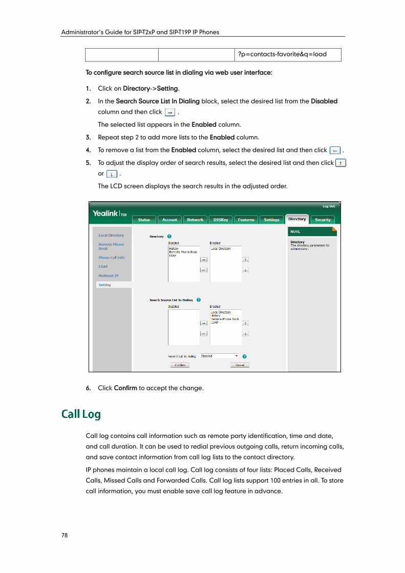
Administrator’s Guide for SIP-T2xP and SIP-T19P IP Phones
78
?p=contacts-favorite&q=load
To configure search source list in dialing via web user interface:
1. Click on Directory->Setting.
2. In the Search Source List In Dialing block, select the desired list from the Disabled
column and then click .
The selected list appears in the Enabled column.
3. Repeat step 2 to add more lists to the Enabled column.
4. To remove a list from the Enabled column, select the desired list and then click .
5. To adjust the display order of search results, select the desired list and then click
or .
The LCD screen displays the search results in the adjusted order.
6. Click Confirm to accept the change.
Call log contains call information such as remote party identification, time and date,
and call duration. It can be used to redial previous outgoing calls, return incoming calls,
and save contact information from call log lists to the contact directory.
IP phones maintain a local call log. Call log consists of four lists: Placed Calls, Received
Calls, Missed Calls and Forwarded Calls. Call log lists support 100 entries in all. To store
call information, you must enable save call log feature in advance.
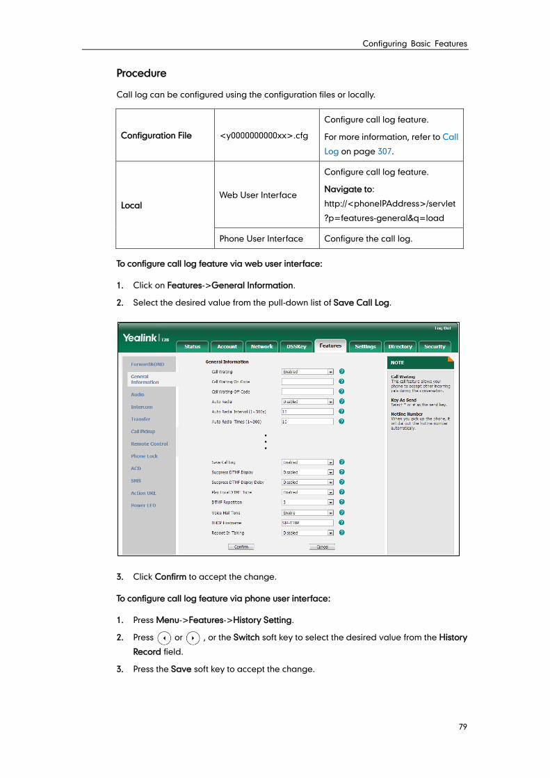
Configuring Basic Features
79
Procedure
Call log can be configured using the configuration files or locally.
Configuration File <y0000000000xx>.cfg
Configure call log feature.
For more information, refer to Call
Log on page 307.
Local Web User Interface
Configure call log feature.
Navigate to:
http://<phoneIPAddress>/servlet
?p=features-general&q=load
Phone User Interface Configure the call log.
To configure call log feature via web user interface:
1. Click on Features->General Information.
2. Select the desired value from the pull-down list of Save Call Log.
3. Click Confirm to accept the change.
To configure call log feature via phone user interface:
1. Press Menu->Features->History Setting.
2. Press or , or the Switch soft key to select the desired value from the History
Record field.
3. Press the Save soft key to accept the change.
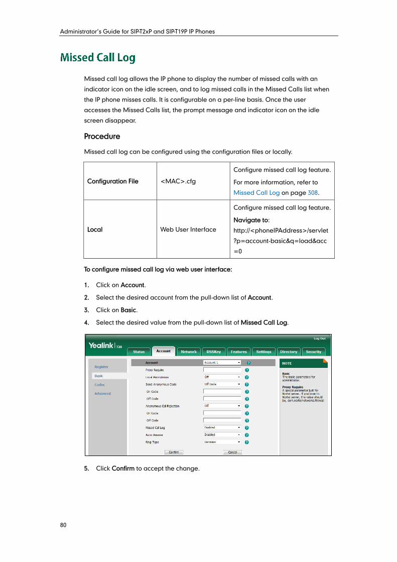
Administrator’s Guide for SIP-T2xP and SIP-T19P IP Phones
80
Missed call log allows the IP phone to display the number of missed calls with an
indicator icon on the idle screen, and to log missed calls in the Missed Calls list when
the IP phone misses calls. It is configurable on a per-line basis. Once the user
accesses the Missed Calls list, the prompt message and indicator icon on the idle
screen disappear.
Procedure
Missed call log can be configured using the configuration files or locally.
Configuration File <MAC>.cfg
Configure missed call log feature.
For more information, refer to
Missed Call Log on page 308.
Local Web User Interface
Configure missed call log feature.
Navigate to:
http://<phoneIPAddress>/servlet
?p=account-basic&q=load&acc
=0
To configure missed call log via web user interface:
1. Click on Account.
2. Select the desired account from the pull-down list of Account.
3. Click on Basic.
4. Select the desired value from the pull-down list of Missed Call Log.
5. Click Confirm to accept the change.
Configuring Basic Features
81
IP phones maintain a local directory. The local directory can store up to 1000 contacts
and 5 groups. When adding a contact to the local directory, in addition to name and
phone numbers, you can also specify the account, ring tone and group for the contact.
Contacts and groups can be added either one by one or in batch using a local contact
file. For more information on how to customize a contact file, refer to Local Contact File
on page 244.
Procedure
Configuration changes can be performed using the configuration files or locally.
Configuration File <y0000000000xx>.cfg
Specify the access URL of the
local contact file.
For more information, refer to
Access URL of Local Contact File
on page 408.
Local
Web User Interface
Add a group and a contact to the
local directory.
Navigate to:
http://<phoneIPAddress>/servlet
?p=contactsbasic&q=load&num
=1&group=
Phone User Interface Add a group and a contact to the
local directory.
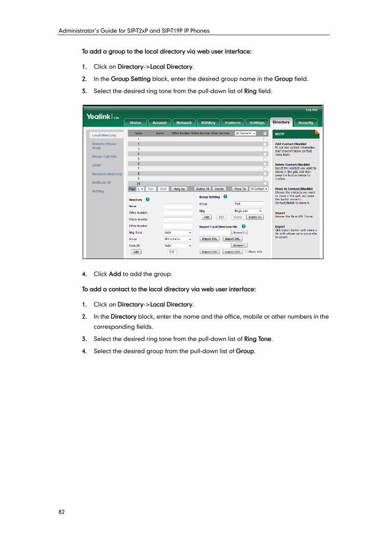
Administrator’s Guide for SIP-T2xP and SIP-T19P IP Phones
82
To add a group to the local directory via web user interface:
1. Click on Directory->Local Directory.
2. In the Group Setting block, enter the desired group name in the Group field.
3. Select the desired ring tone from the pull-down list of Ring field.
4. Click Add to add the group.
To add a contact to the local directory via web user interface:
1. Click on Directory->Local Directory.
2. In the Directory block, enter the name and the office, mobile or other numbers in the
corresponding fields.
3. Select the desired ring tone from the pull-down list of Ring Tone.
4. Select the desired group from the pull-down list of Group.
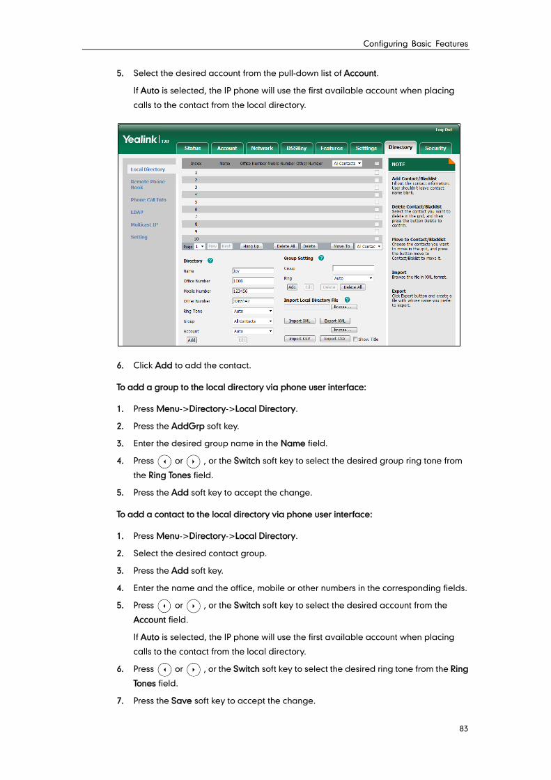
Configuring Basic Features
83
5. Select the desired account from the pull-down list of Account.
If Auto is selected, the IP phone will use the first available account when placing
calls to the contact from the local directory.
6. Click Add to add the contact.
To add a group to the local directory via phone user interface:
1. Press Menu->Directory->Local Directory.
2. Press the AddGrp soft key.
3. Enter the desired group name in the Name field.
4. Press or , or the Switch soft key to select the desired group ring tone from
the Ring Tones field.
5. Press the Add soft key to accept the change.
To add a contact to the local directory via phone user interface:
1. Press Menu->Directory->Local Directory.
2. Select the desired contact group.
3. Press the Add soft key.
4. Enter the name and the office, mobile or other numbers in the corresponding fields.
5. Press or , or the Switch soft key to select the desired account from the
Account field.
If Auto is selected, the IP phone will use the first available account when placing
calls to the contact from the local directory.
6. Press or , or the Switch soft key to select the desired ring tone from the Ring
Tones field.
7. Press the Save soft key to accept the change.
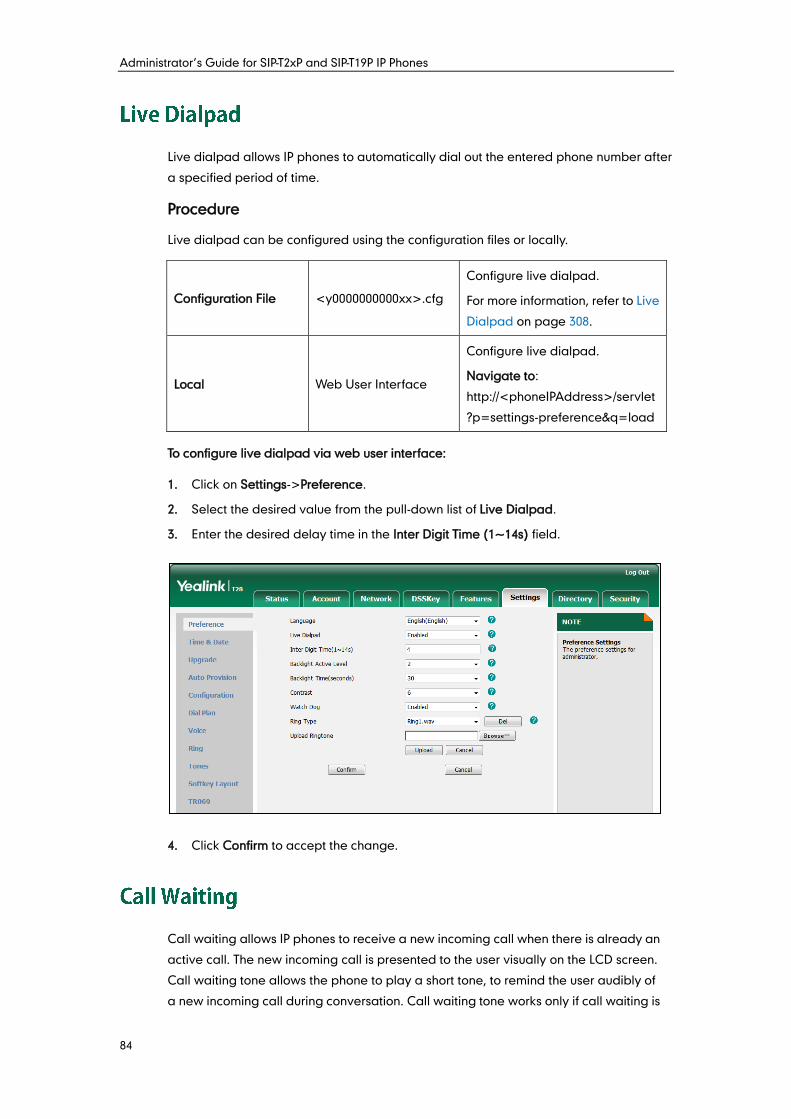
Administrator’s Guide for SIP-T2xP and SIP-T19P IP Phones
84
Live dialpad allows IP phones to automatically dial out the entered phone number after
a specified period of time.
Procedure
Live dialpad can be configured using the configuration files or locally.
Configuration File <y0000000000xx>.cfg
Configure live dialpad.
For more information, refer to Live
Dialpad on page 308.
Local Web User Interface
Configure live dialpad.
Navigate to:
http://<phoneIPAddress>/servlet
?p=settings-preference&q=load
To configure live dialpad via web user interface:
1. Click on Settings->Preference.
2. Select the desired value from the pull-down list of Live Dialpad.
3. Enter the desired delay time in the Inter Digit Time (1~14s) field.
4. Click Confirm to accept the change.
Call waiting allows IP phones to receive a new incoming call when there is already an
active call. The new incoming call is presented to the user visually on the LCD screen.
Call waiting tone allows the phone to play a short tone, to remind the user audibly of
a new incoming call during conversation. Call waiting tone works only if call waiting is
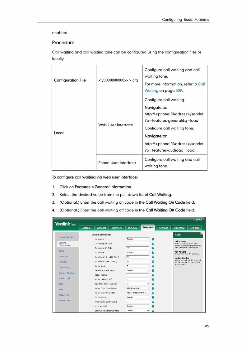
Configuring Basic Features
85
enabled.
Procedure
Call waiting and call waiting tone can be configured using the configuration files or
locally.
Configuration File <y0000000000xx>.cfg
Configure call waiting and call
waiting tone.
For more information, refer to Call
Waiting on page 309.
Local
Web User Interface
Configure call waiting.
Navigate to:
http://<phoneIPAddress>/servlet
?p=features-general&q=load
Configure call waiting tone.
Navigate to:
http://<phoneIPAddress>/servlet
?p=features-audio&q=load
Phone User Interface Configure call waiting and call
waiting tone.
To configure call waiting via web user interface:
1. Click on Features->General Information.
2. Select the desired value from the pull-down list of Call Waiting.
3. (Optional.) Enter the call waiting on code in the Call Waiting On Code field.
4. (Optional.) Enter the call waiting off code in the Call Waiting Off Code field.
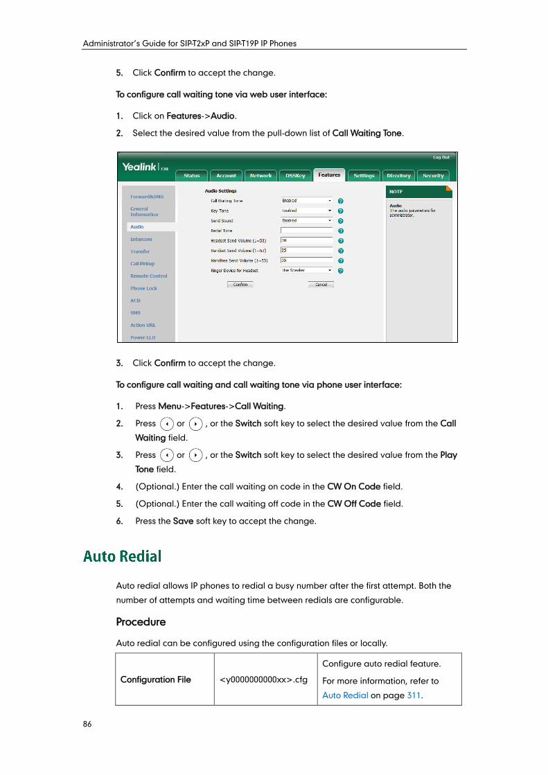
Administrator’s Guide for SIP-T2xP and SIP-T19P IP Phones
86
5. Click Confirm to accept the change.
To configure call waiting tone via web user interface:
1. Click on Features->Audio.
2. Select the desired value from the pull-down list of Call Waiting Tone.
3. Click Confirm to accept the change.
To configure call waiting and call waiting tone via phone user interface:
1. Press Menu->Features->Call Waiting.
2. Press or , or the Switch soft key to select the desired value from the Call
Waiting field.
3. Press or , or the Switch soft key to select the desired value from the Play
Tone field.
4. (Optional.) Enter the call waiting on code in the CW On Code field.
5. (Optional.) Enter the call waiting off code in the CW Off Code field.
6. Press the Save soft key to accept the change.
Auto redial allows IP phones to redial a busy number after the first attempt. Both the
number of attempts and waiting time between redials are configurable.
Procedure
Auto redial can be configured using the configuration files or locally.
Configuration File <y0000000000xx>.cfg
Configure auto redial feature.
For more information, refer to
Auto Redial on page 311.
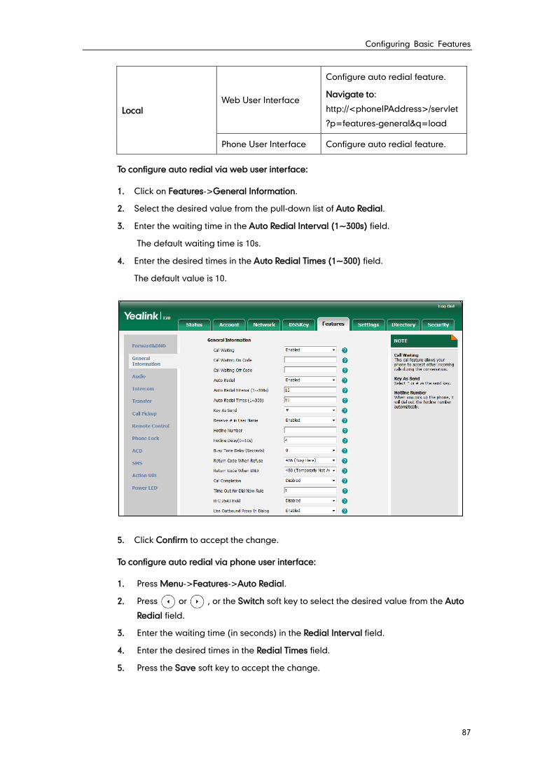
Configuring Basic Features
87
Local Web User Interface
Configure auto redial feature.
Navigate to:
http://<phoneIPAddress>/servlet
?p=features-general&q=load
Phone User Interface Configure auto redial feature.
To configure auto redial via web user interface:
1. Click on Features->General Information.
2. Select the desired value from the pull-down list of Auto Redial.
3. Enter the waiting time in the Auto Redial Interval (1~300s) field.
The default waiting time is 10s.
4. Enter the desired times in the Auto Redial Times (1~300) field.
The default value is 10.
5. Click Confirm to accept the change.
To configure auto redial via phone user interface:
1. Press Menu->Features->Auto Redial.
2. Press or , or the Switch soft key to select the desired value from the Auto
Redial field.
3. Enter the waiting time (in seconds) in the Redial Interval field.
4. Enter the desired times in the Redial Times field.
5. Press the Save soft key to accept the change.
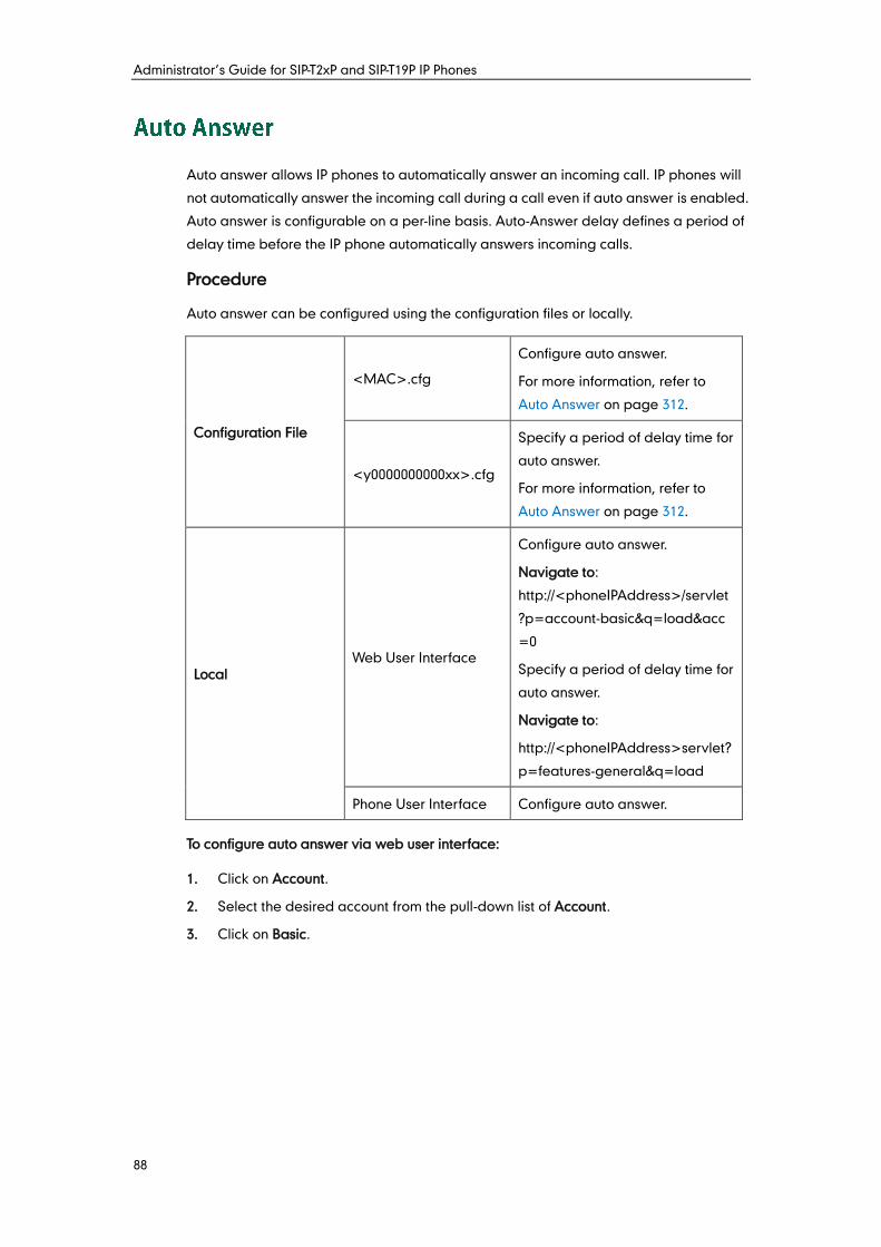
Administrator’s Guide for SIP-T2xP and SIP-T19P IP Phones
88
Auto answer allows IP phones to automatically answer an incoming call. IP phones will
not automatically answer the incoming call during a call even if auto answer is enabled.
Auto answer is configurable on a per-line basis. Auto-Answer delay defines a period of
delay time before the IP phone automatically answers incoming calls.
Procedure
Auto answer can be configured using the configuration files or locally.
Configuration File
<MAC>.cfg
Configure auto answer.
For more information, refer to
Auto Answer on page 312.
<y0000000000xx>.cfg
Specify a period of delay time for
auto answer.
For more information, refer to
Auto Answer on page 312.
Local Web User Interface
Configure auto answer.
Navigate to:
http://<phoneIPAddress>/servlet
?p=account-basic&q=load&acc
=0
Specify a period of delay time for
auto answer.
Navigate to:
http://<phoneIPAddress>servlet?
p=features-general&q=load
Phone User Interface Configure auto answer.
To configure auto answer via web user interface:
1. Click on Account.
2. Select the desired account from the pull-down list of Account.
3. Click on Basic.
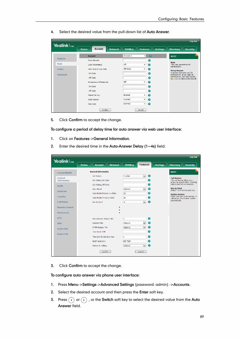
Configuring Basic Features
89
4. Select the desired value from the pull-down list of Auto Answer.
5. Click Confirm to accept the change.
To configure a period of delay time for auto answer via web user interface:
1. Click on Features->General Information.
2. Enter the desired time in the Auto-Answer Delay (1~4s) field.
3. Click Confirm to accept the change.
To configure auto answer via phone user interface:
1. Press Menu->Settings->Advanced Settings (password: admin) ->Accounts.
2. Select the desired account and then press the Enter soft key.
3. Press or , or the Switch soft key to select the desired value from the Auto
Answer field.
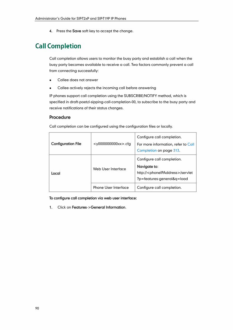
Administrator’s Guide for SIP-T2xP and SIP-T19P IP Phones
90
4. Press the Save soft key to accept the change.
Call completion allows users to monitor the busy party and establish a call when the
busy party becomes available to receive a call. Two factors commonly prevent a call
from connecting successfully:
Callee does not answer
Callee actively rejects the incoming call before answering
IP phones support call completion using the SUBSCRIBE/NOTIFY method, which is
specified in draft-poetzl-sipping-call-completion-00, to subscribe to the busy party and
receive notifications of their status changes.
Procedure
Call completion can be configured using the configuration files or locally.
Configuration File <y0000000000xx>.cfg
Configure call completion.
For more information, refer to Call
Completion on page 313.
Local Web User Interface
Configure call completion.
Navigate to:
http://<phoneIPAddress>/servlet
?p=features-general&q=load
Phone User Interface Configure call completion.
To configure call completion via web user interface:
1. Click on Features->General Information.
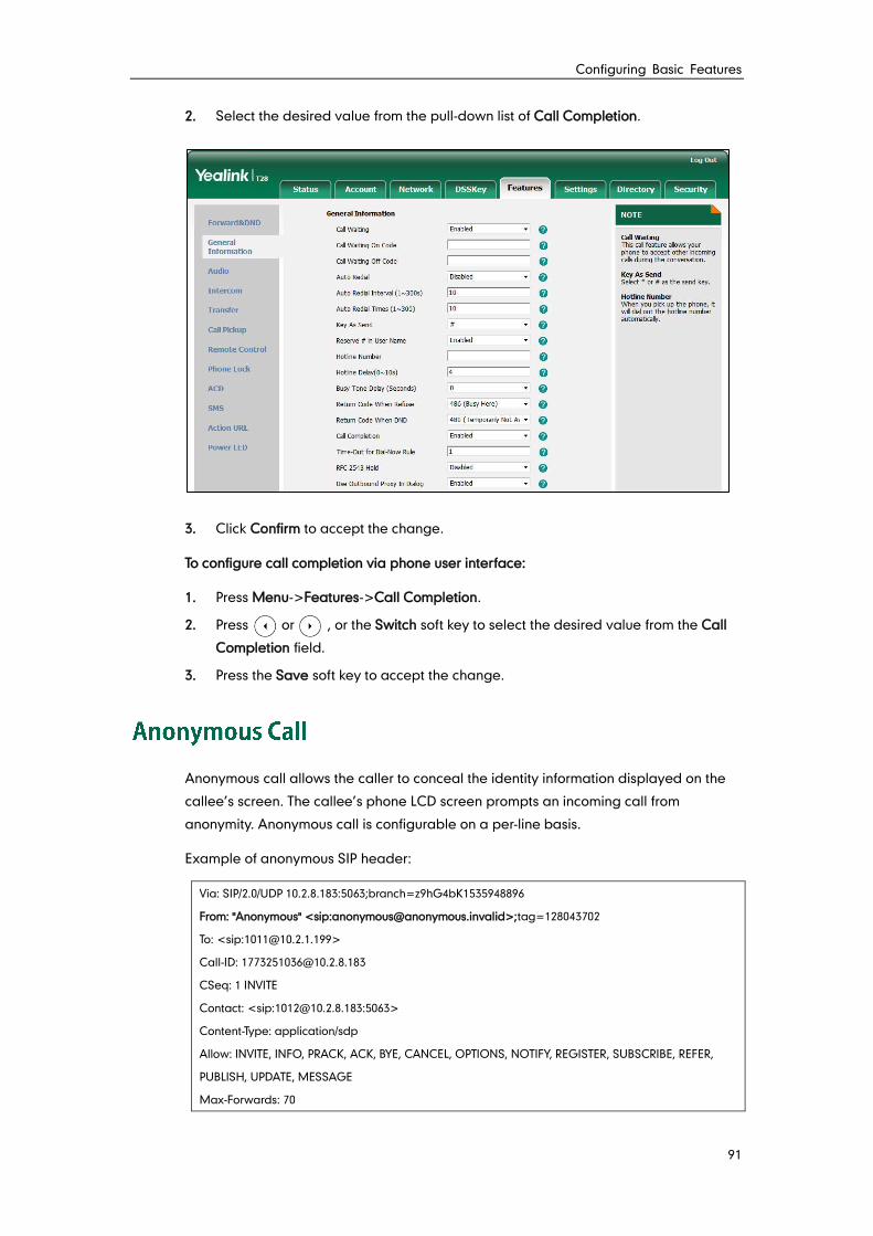
Configuring Basic Features
91
2. Select the desired value from the pull-down list of Call Completion.
3. Click Confirm to accept the change.
To configure call completion via phone user interface:
1. Press Menu->Features->Call Completion.
2. Press or , or the Switch soft key to select the desired value from the Call
Completion field.
3. Press the Save soft key to accept the change.
Anonymous call allows the caller to conceal the identity information displayed on the
callee’s screen. The callee’s phone LCD screen prompts an incoming call from
anonymity. Anonymous call is configurable on a per-line basis.
Example of anonymous SIP header:
Via: SIP/2.0/UDP 10.2.8.183:5063;branch=z9hG4bK1535948896
From: "Anonymous" <sip:[email protected]>;tag=128043702
To: <sip:[email protected]>
Call-ID: [email protected]
CSeq: 1 INVITE
Contact: <sip:[email protected]:5063>
Content-Type: application/sdp
Allow: INVITE, INFO, PRACK, ACK, BYE, CANCEL, OPTIONS, NOTIFY, REGISTER, SUBSCRIBE, REFER,
PUBLISH, UPDATE, MESSAGE
Max-Forwards: 70
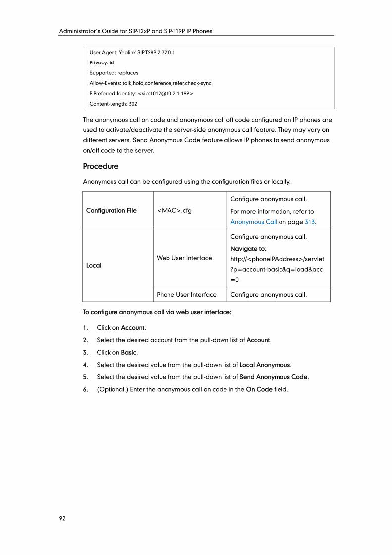
Administrator’s Guide for SIP-T2xP and SIP-T19P IP Phones
92
User-Agent: Yealink SIP-T28P 2.72.0.1
Privacy: id
Supported: replaces
Allow-Events: talk,hold,conference,refer,check-sync
P-Preferred-Identity: <sip:[email protected]>
Content-Length: 302
The anonymous call on code and anonymous call off code configured on IP phones are
used to activate/deactivate the server-side anonymous call feature. They may vary on
different servers. Send Anonymous Code feature allows IP phones to send anonymous
on/off code to the server.
Procedure
Anonymous call can be configured using the configuration files or locally.
Configuration File <MAC>.cfg
Configure anonymous call.
For more information, refer to
Anonymous Call on page 313.
Local Web User Interface
Configure anonymous call.
Navigate to:
http://<phoneIPAddress>/servlet
?p=account-basic&q=load&acc
=0
Phone User Interface Configure anonymous call.
To configure anonymous call via web user interface:
1. Click on Account.
2. Select the desired account from the pull-down list of Account.
3. Click on Basic.
4. Select the desired value from the pull-down list of Local Anonymous.
5. Select the desired value from the pull-down list of Send Anonymous Code.
6. (Optional.) Enter the anonymous call on code in the On Code field.
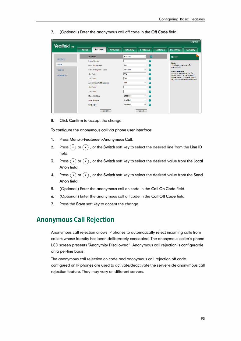
Configuring Basic Features
93
7. (Optional.) Enter the anonymous call off code in the Off Code field.
8. Click Confirm to accept the change.
To configure the anonymous call via phone user interface:
1. Press Menu->Features->Anonymous Call.
2. Press or , or the Switch soft key to select the desired line from the Line ID
field.
3. Press or , or the Switch soft key to select the desired value from the Local
Anon field.
4. Press or , or the Switch soft key to select the desired value from the Send
Anon field.
5. (Optional.) Enter the anonymous call on code in the Call On Code field.
6. (Optional.) Enter the anonymous call off code in the Call Off Code field.
7. Press the Save soft key to accept the change.
Anonymous call rejection allows IP phones to automatically reject incoming calls from
callers whose identity has been deliberately concealed. The anonymous caller’s phone
LCD screen presents “Anonymity Disallowed”. Anonymous call rejection is configurable
on a per-line basis.
The anonymous call rejection on code and anonymous call rejection off code
configured on IP phones are used to activate/deactivate the server-side anonymous call
rejection feature. They may vary on different servers.
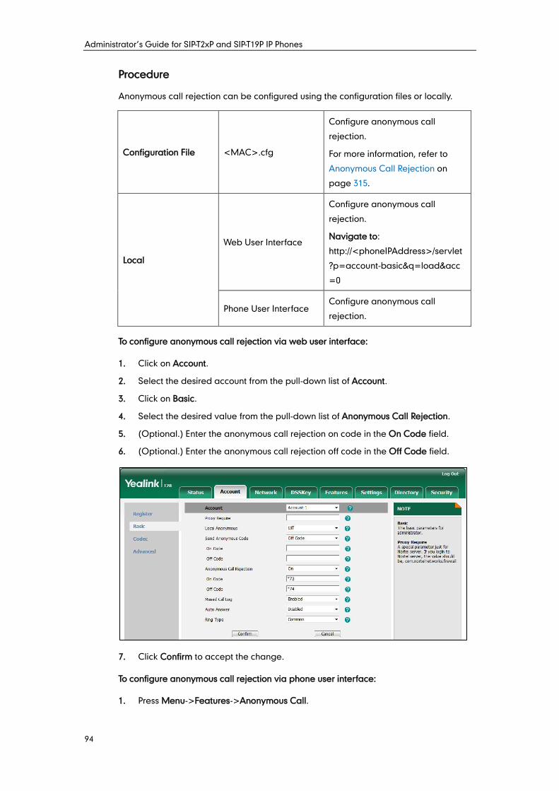
Administrator’s Guide for SIP-T2xP and SIP-T19P IP Phones
94
Procedure
Anonymous call rejection can be configured using the configuration files or locally.
Configuration File <MAC>.cfg
Configure anonymous call
rejection.
For more information, refer to
Anonymous Call Rejection on
page 315.
Local
Web User Interface
Configure anonymous call
rejection.
Navigate to:
http://<phoneIPAddress>/servlet
?p=account-basic&q=load&acc
=0
Phone User Interface Configure anonymous call
rejection.
To configure anonymous call rejection via web user interface:
1. Click on Account.
2. Select the desired account from the pull-down list of Account.
3. Click on Basic.
4. Select the desired value from the pull-down list of Anonymous Call Rejection.
5. (Optional.) Enter the anonymous call rejection on code in the On Code field.
6. (Optional.) Enter the anonymous call rejection off code in the Off Code field.
7. Click Confirm to accept the change.
To configure anonymous call rejection via phone user interface:
1. Press Menu->Features->Anonymous Call.
Configuring Basic Features
95
2. Press or , or the Switch soft key to select the desired line from the Line ID
field.
3. Press or , or the Switch soft key to select the desired value from the Anon
Rejection field.
4. (Optional.) Enter the anonymous call rejection on code in the Reject On Code field.
5. (Optional.) Enter the anonymous call rejection off code in the Reject Off Code field.
6. Press the Save soft key to accept the change.
Do Not Disturb (DND) allows IP phones to ignore incoming calls. DND feature can be
configured on a phone or a per-line basis depending on the DND mode. Two DND
modes:
Phone (default): DND feature is effective for the IP phone.
Custom: DND feature can be configured for each or all accounts.
A user can activate or deactivate DND using the DND key or DND soft key (not
applicable to SIP-T20P IP phones). The server-side DND feature disables the local DND
and call forward settings. If the server-side DND feature is enabled on any of the
phone’s registrations, the other registrations are not affected. For more information on
call forward, refer to Call Forward on page 110.
The DND on code and DND off code configured on IP phones are used to
activate/deactivate the server-side DND feature. They may vary on different servers.
Return Message When DND
This feature defines the return code and the reason of the SIP response message for the
rejected incoming call when DND is enabled on the IP phone. The caller’s phone LCD
screen displays the received return code.
Procedure
DND can be configured using the configuration files or locally.
Configuration File
<MAC>.cfg
Configure DND in the custom
mode.
For more information, refer to Do
Not Disturb on page 316.
<y0000000000xx>.cfg
Assign a DND key.
For more information, refer to DND
Key on page 420.
Configure the DND mode.
Configure DND in the phone
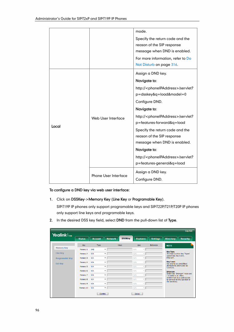
Administrator’s Guide for SIP-T2xP and SIP-T19P IP Phones
96
mode.
Specify the return code and the
reason of the SIP response
message when DND is enabled.
For more information, refer to Do
Not Disturb on page 316.
Local
Web User Interface
Assign a DND key.
Navigate to:
http://<phoneIPAddress>/servlet?
p=dsskey&q=load&model=0
Configure DND.
Navigate to:
http://<phoneIPAddress>/servlet?
p=features-forward&q=load
Specify the return code and the
reason of the SIP response
message when DND is enabled.
Navigate to:
http://<phoneIPAddress>/servlet?
p=features-general&q=load
Phone User Interface Assign a DND key.
Configure DND.
To configure a DND key via web user interface:
1. Click on DSSKey->Memory Key (Line Key or Programable Key).
SIP-T19P IP phones only support programable keys and SIP-T22P/T21P/T20P IP phones
only support line keys and programable keys.
2. In the desired DSS key field, select DND from the pull-down list of Type.
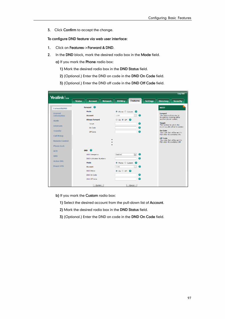
Configuring Basic Features
97
3. Click Confirm to accept the change.
To configure DND feature via web user interface:
1. Click on Features->Forward & DND.
2. In the DND block, mark the desired radio box in the Mode field.
a) If you mark the Phone radio box:
1) Mark the desired radio box in the DND Status field.
2) (Optional.) Enter the DND on code in the DND On Code field.
3) (Optional.) Enter the DND off code in the DND Off Code field.
b) If you mark the Custom radio box:
1) Select the desired account from the pull-down list of Account.
2) Mark the desired radio box in the DND Status field.
3) (Optional.) Enter the DND on code in the DND On Code field.
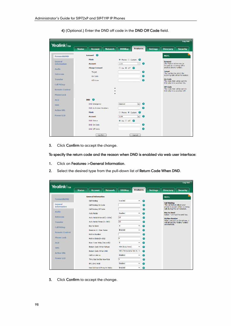
Administrator’s Guide for SIP-T2xP and SIP-T19P IP Phones
98
4) (Optional.) Enter the DND off code in the DND Off Code field.
3. Click Confirm to accept the change.
To specify the return code and the reason when DND is enabled via web user interface:
1. Click on Features->General Information.
2. Select the desired type from the pull-down list of Return Code When DND.
3. Click Confirm to accept the change.
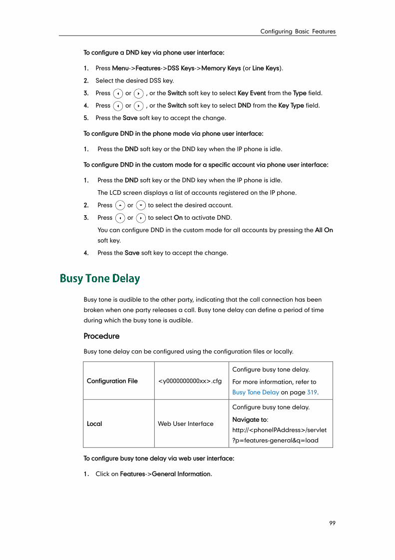
Configuring Basic Features
99
To configure a DND key via phone user interface:
1. Press Menu->Features->DSS Keys->Memory Keys (or Line Keys).
2. Select the desired DSS key.
3. Press or , or the Switch soft key to select Key Event from the Type field.
4. Press or , or the Switch soft key to select DND from the Key Type field.
5. Press the Save soft key to accept the change.
To configure DND in the phone mode via phone user interface:
1. Press the DND soft key or the DND key when the IP phone is idle.
To configure DND in the custom mode for a specific account via phone user interface:
1. Press the DND soft key or the DND key when the IP phone is idle.
The LCD screen displays a list of accounts registered on the IP phone.
2. Press or to select the desired account.
3. Press or to select On to activate DND.
You can configure DND in the custom mode for all accounts by pressing the All On
soft key.
4. Press the Save soft key to accept the change.
Busy tone is audible to the other party, indicating that the call connection has been
broken when one party releases a call. Busy tone delay can define a period of time
during which the busy tone is audible.
Procedure
Busy tone delay can be configured using the configuration files or locally.
Configuration File <y0000000000xx>.cfg
Configure busy tone delay.
For more information, refer to
Busy Tone Delay on page 319.
Local Web User Interface
Configure busy tone delay.
Navigate to:
http://<phoneIPAddress>/servlet
?p=features-general&q=load
To configure busy tone delay via web user interface:
1. Click on Features->General Information.
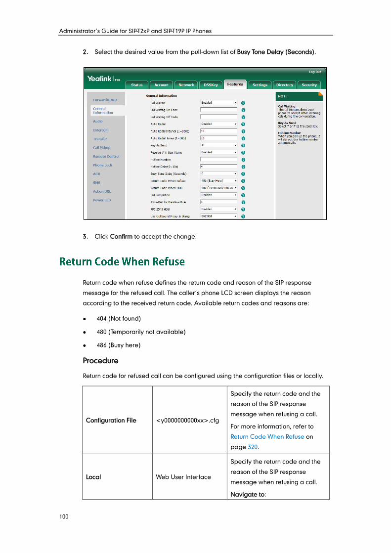
Administrator’s Guide for SIP-T2xP and SIP-T19P IP Phones
100
2. Select the desired value from the pull-down list of Busy Tone Delay (Seconds).
3. Click Confirm to accept the change.
Return code when refuse defines the return code and reason of the SIP response
message for the refused call. The caller’s phone LCD screen displays the reason
according to the received return code. Available return codes and reasons are:
404 (Not found)
480 (Temporarily not available)
486 (Busy here)
Procedure
Return code for refused call can be configured using the configuration files or locally.
Configuration File <y0000000000xx>.cfg
Specify the return code and the
reason of the SIP response
message when refusing a call.
For more information, refer to
Return Code When Refuse on
page 320.
Local Web User Interface
Specify the return code and the
reason of the SIP response
message when refusing a call.
Navigate to:
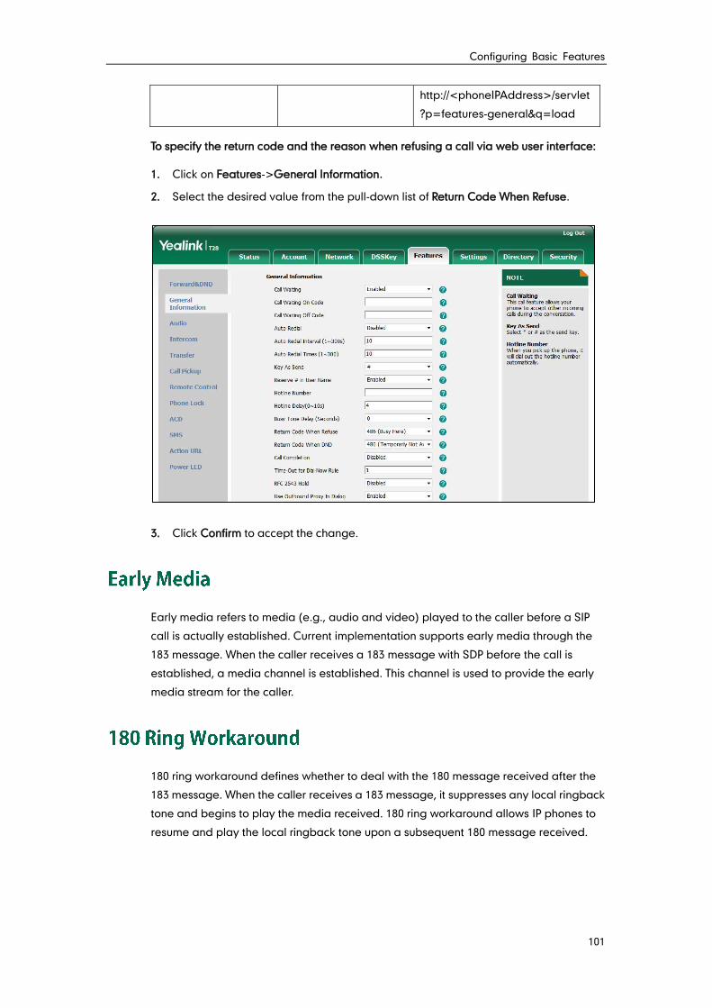
Configuring Basic Features
101
http://<phoneIPAddress>/servlet
?p=features-general&q=load
To specify the return code and the reason when refusing a call via web user interface:
1. Click on Features->General Information.
2. Select the desired value from the pull-down list of Return Code When Refuse.
3. Click Confirm to accept the change.
Early media refers to media (e.g., audio and video) played to the caller before a SIP
call is actually established. Current implementation supports early media through the
183 message. When the caller receives a 183 message with SDP before the call is
established, a media channel is established. This channel is used to provide the early
media stream for the caller.
180 ring workaround defines whether to deal with the 180 message received after the
183 message. When the caller receives a 183 message, it suppresses any local ringback
tone and begins to play the media received. 180 ring workaround allows IP phones to
resume and play the local ringback tone upon a subsequent 180 message received.
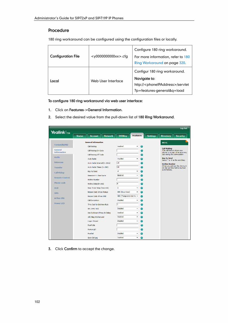
Administrator’s Guide for SIP-T2xP and SIP-T19P IP Phones
102
Procedure
180 ring workaround can be configured using the configuration files or locally.
Configuration File <y0000000000xx>.cfg
Configure 180 ring workaround.
For more information, refer to 180
Ring Workaround on page 320.
Local Web User Interface
Configur 180 ring workaround.
Navigate to:
http://<phoneIPAddress>/servlet
?p=features-general&q=load
To configure 180 ring workaround via web user interface:
1. Click on Features->General Information.
2. Select the desired value from the pull-down list of 180 Ring Workaround.
3. Click Confirm to accept the change.
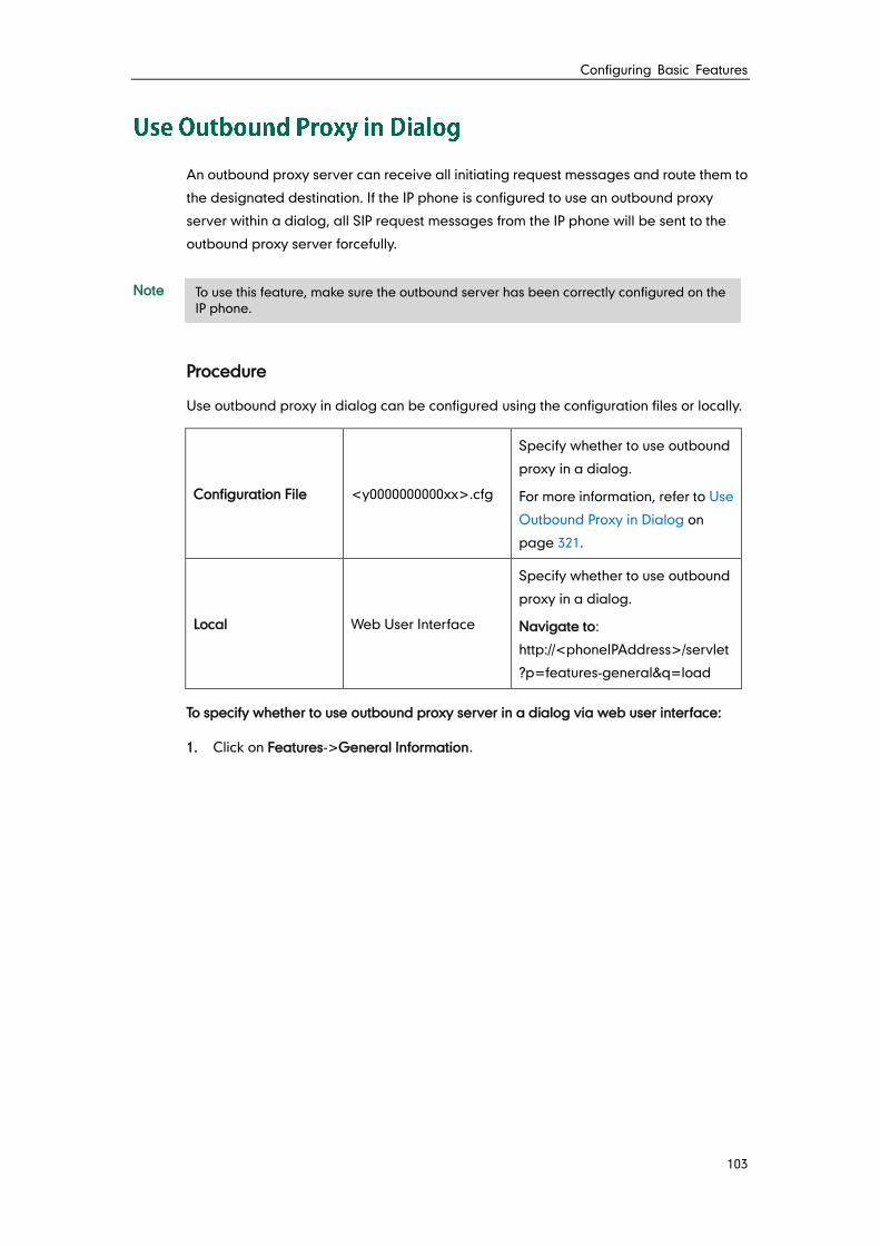
Configuring Basic Features
103
An outbound proxy server can receive all initiating request messages and route them to
the designated destination. If the IP phone is configured to use an outbound proxy
server within a dialog, all SIP request messages from the IP phone will be sent to the
outbound proxy server forcefully.
Note
Procedure
Use outbound proxy in dialog can be configured using the configuration files or locally.
Configuration File <y0000000000xx>.cfg
Specify whether to use outbound
proxy in a dialog.
For more information, refer to Use
Outbound Proxy in Dialog on
page 321.
Local Web User Interface
Specify whether to use outbound
proxy in a dialog.
Navigate to:
http://<phoneIPAddress>/servlet
?p=features-general&q=load
To specify whether to use outbound proxy server in a dialog via web user interface:
1. Click on Features->General Information.
To use this feature, make sure the outbound server has been correctly configured on the
IP phone.
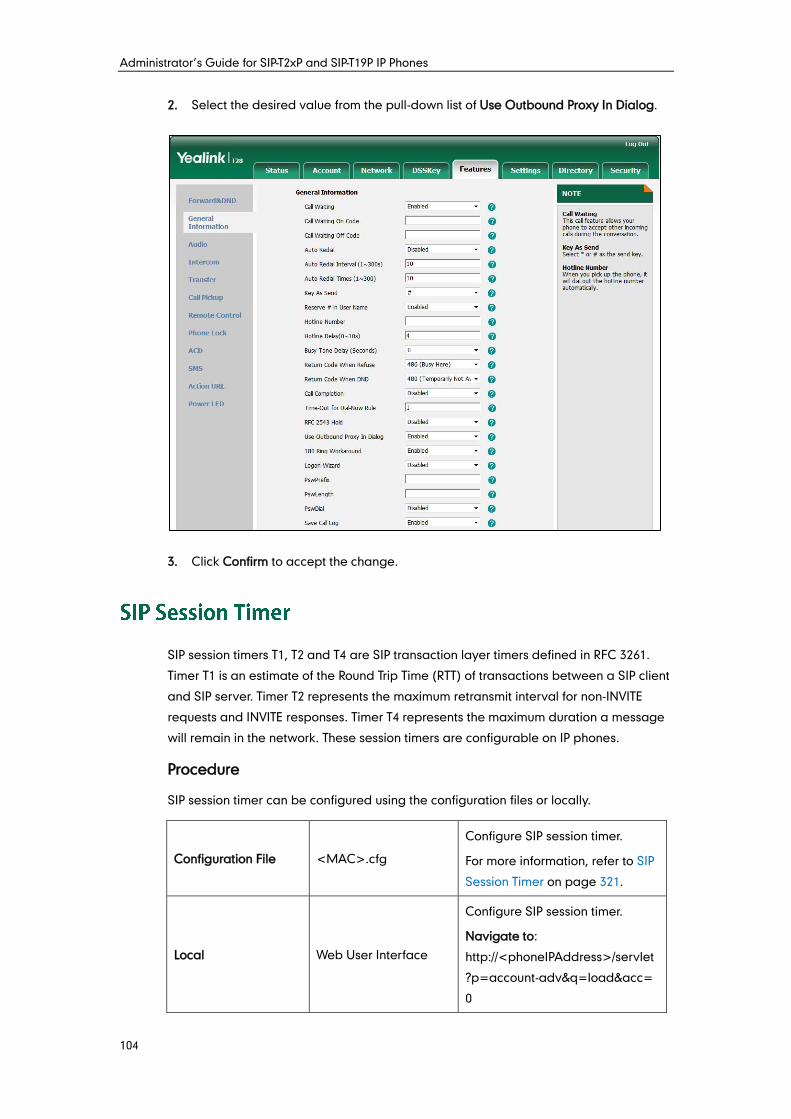
Administrator’s Guide for SIP-T2xP and SIP-T19P IP Phones
104
2. Select the desired value from the pull-down list of Use Outbound Proxy In Dialog.
3. Click Confirm to accept the change.
SIP session timers T1, T2 and T4 are SIP transaction layer timers defined in RFC 3261.
Timer T1 is an estimate of the Round Trip Time (RTT) of transactions between a SIP client
and SIP server. Timer T2 represents the maximum retransmit interval for non-INVITE
requests and INVITE responses. Timer T4 represents the maximum duration a message
will remain in the network. These session timers are configurable on IP phones.
Procedure
SIP session timer can be configured using the configuration files or locally.
Configuration File <MAC>.cfg
Configure SIP session timer.
For more information, refer to SIP
Session Timer on page 321.
Local Web User Interface
Configure SIP session timer.
Navigate to:
http://<phoneIPAddress>/servlet
?p=account-adv&q=load&acc=
0
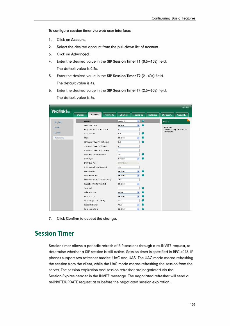
Configuring Basic Features
105
To configure session timer via web user interface:
1. Click on Account.
2. Select the desired account from the pull-down list of Account.
3. Click on Advanced.
4. Enter the desired value in the SIP Session Timer T1 (0.5~10s) field.
The default value is 0.5s.
5. Enter the desired value in the SIP Session Timer T2 (2~40s) field.
The default value is 4s.
6. Enter the desired value in the SIP Session Timer T4 (2.5~60s) field.
The default value is 5s.
7. Click Confirm to accept the change.
Session timer allows a periodic refresh of SIP sessions through a re-INVITE request, to
determine whether a SIP session is still active. Session timer is specified in RFC 4028. IP
phones support two refresher modes: UAC and UAS. The UAC mode means refreshing
the session from the client, while the UAS mode means refreshing the session from the
server. The session expiration and session refresher are negotiated via the
Session-Expires header in the INVITE message. The negotiated refresher will send a
re-INVITE/UPDATE request at or before the negotiated session expiration.
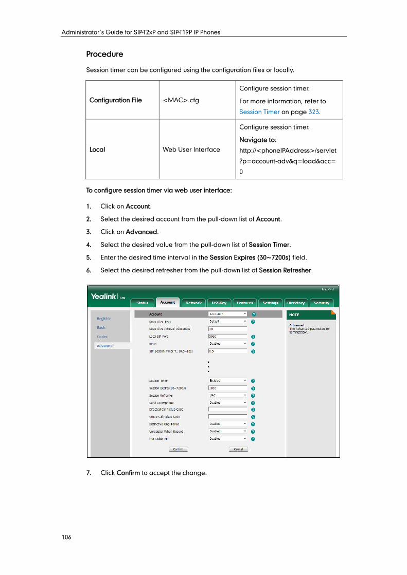
Administrator’s Guide for SIP-T2xP and SIP-T19P IP Phones
106
Procedure
Session timer can be configured using the configuration files or locally.
Configuration File <MAC>.cfg
Configure session timer.
For more information, refer to
Session Timer on page 323.
Local Web User Interface
Configure session timer.
Navigate to:
http://<phoneIPAddress>/servlet
?p=account-adv&q=load&acc=
0
To configure session timer via web user interface:
1. Click on Account.
2. Select the desired account from the pull-down list of Account.
3. Click on Advanced.
4. Select the desired value from the pull-down list of Session Timer.
5. Enter the desired time interval in the Session Expires (30~7200s) field.
6. Select the desired refresher from the pull-down list of Session Refresher.
7. Click Confirm to accept the change.
Configuring Basic Features
107
Call hold provides a service of placing an active call on hold. When a call is placed on
hold, the IP phones send an INVITE request with HOLD SDP to request remote parties to
stop sending media and to inform them that they are being held. IP phones support two
call hold methods, one is RFC 3264, which sets the “a” (media attribute) in the SDP to
sendonly, recvonly or inactive (e.g., a=sendonly). The other is RFC 2543, which sets the
“c” (connection addresses for the media streams) in the SDP to zero (e.g., c=0.0.0.0).
Call hold tone allows IP phones to play a warning tone at regular intervals when there is
a call on hold. The warning tone is played through the speakerphone.
IP phones also support Music on Hold (MoH) feature. MoH is the business practice of
playing recorded music to fill the silence that would be heard by the party who has
been placed on hold. To use this feature, specify a SIP URI pointing to an MoH server
account. When a call is placed on hold, the IP phone will send an INVITE message to the
specified MoH server account according to the SIP URI. The MoH server account
automatically responds to the INVITE message and immediately plays audio from some
source located anywhere (LAN, Internet) to the held party.
Procedure
Call hold can be configured using the configuration files or locally.
Configuration File
<y0000000000xx>.cfg
Configure the call hold tone and
call hold tone delay.
Specify whether RFC 2543
(c=0.0.0.0) outgoing hold
signaling is used.
For more information, refer to Call
Hold on page 324.
<MAC>.cfg
Configure MoH on a per-line
basis.
For more information, refer to Call
Hold on page 324.
Local Web User Interface
Configure the call hold tone and
call hold tone delay.
Specify whether RFC 2543
(c=0.0.0.0) outgoing hold
signaling is used.
Navigate to:
http://<phoneIPAddress>/servlet
?p=features-general&q=load
Configure MoH on a per-line
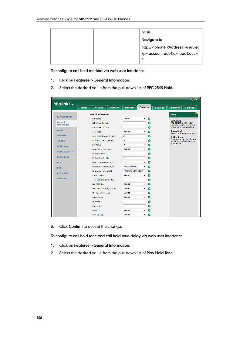
Administrator’s Guide for SIP-T2xP and SIP-T19P IP Phones
108
basis.
Navigate to:
http://<phoneIPAddress>/servlet
?p=account-adv&q=load&acc=
0
To configure call hold method via web user interface:
1. Click on Features->General Information.
2. Select the desired value from the pull-down list of RFC 2543 Hold.
3. Click Confirm to accept the change.
To configure call hold tone and call hold tone delay via web user interface:
1. Click on Features->General Information.
2. Select the desired value from the pull-down list of Play Hold Tone.
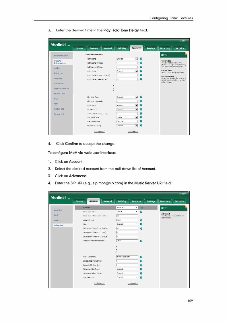
Configuring Basic Features
109
3. Enter the desired time in the Play Hold Tone Delay field.
4. Click Confirm to accept the change.
To configure MoH via web user interface:
1. Click on Account.
2. Select the desired account from the pull-down list of Account.
3. Click on Advanced.
4. Enter the SIP URI (e.g., sip:[email protected]) in the Music Server URI field.
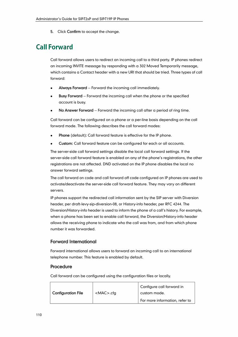
Administrator’s Guide for SIP-T2xP and SIP-T19P IP Phones
110
5. Click Confirm to accept the change.
Call forward allows users to redirect an incoming call to a third party. IP phones redirect
an incoming INVITE message by responding with a 302 Moved Temporarily message,
which contains a Contact header with a new URI that should be tried. Three types of call
forward:
Always Forward -- Forward the incoming call immediately.
Busy Forward -- Forward the incoming call when the phone or the specified
account is busy.
No Answer Forward -- Forward the incoming call after a period of ring time.
Call forward can be configured on a phone or a per-line basis depending on the call
forward mode. The following describes the call forward modes:
Phone (default): Call forward feature is effective for the IP phone.
Custom: Call forward feature can be configured for each or all accounts.
The server-side call forward settings disable the local call forward settings. If the
server-side call forward feature is enabled on any of the phone’s registrations, the other
registrations are not affected. DND activated on the IP phone disables the local no
answer forward settings.
The call forward on code and call forward off code configured on IP phones are used to
activate/deactivate the server-side call forward feature. They may vary on different
servers.
IP phones support the redirected call information sent by the SIP server with Diversion
header, per draft-levy-sip-diversion-08, or History-info header, per RFC 4244. The
Diversion/History-info header is used to inform the phone of a call’s history. For example,
when a phone has been set to enable call forward, the Diversion/History-info header
allows the receiving phone to indicate who the call was from, and from which phone
number it was forwarded.
Forward International
Forward international allows users to forward an incoming call to an international
telephone number. This feature is enabled by default.
Procedure
Call forward can be configured using the configuration files or locally.
Configuration File <MAC>.cfg
Configure call forward in
custom mode.
For more information, refer to
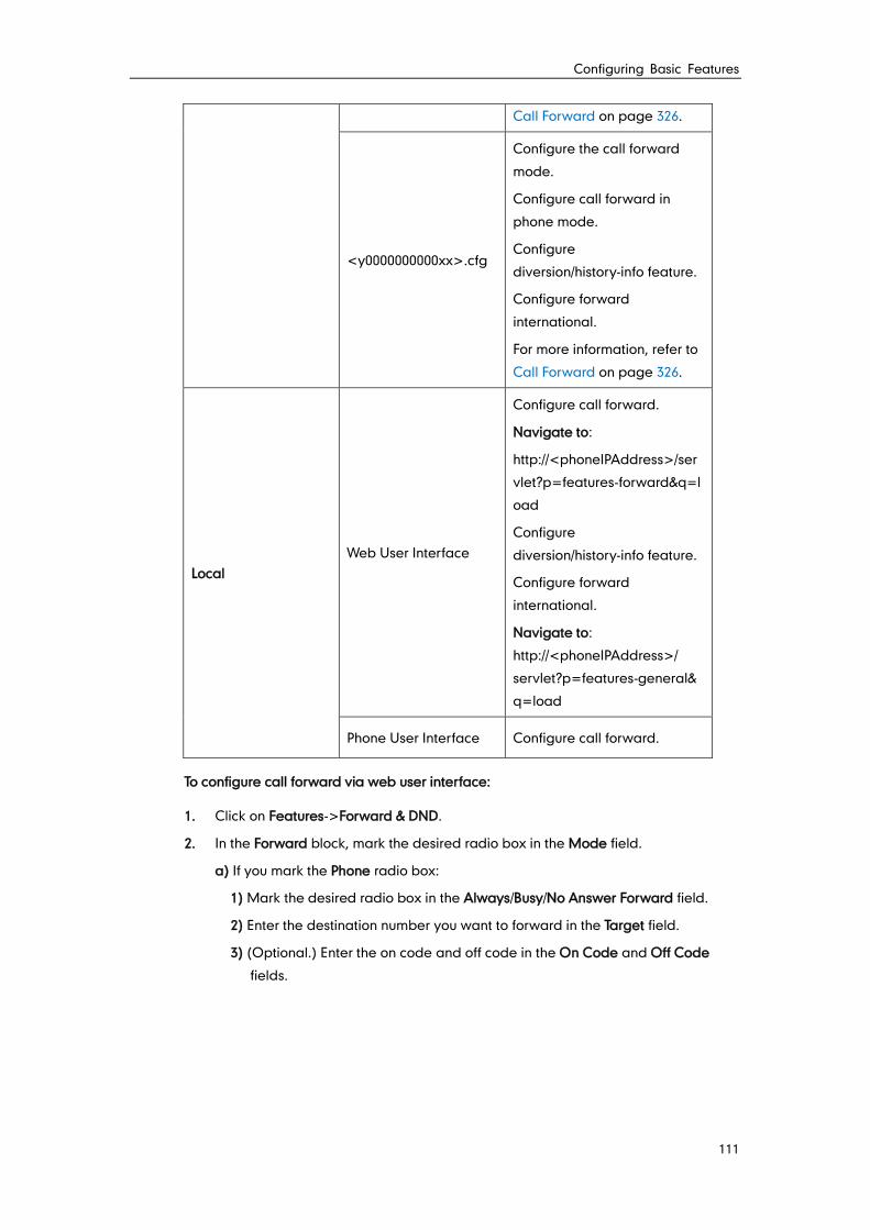
Configuring Basic Features
111
Call Forward on page 326.
<y0000000000xx>.cfg
Configure the call forward
mode.
Configure call forward in
phone mode.
Configure
diversion/history-info feature.
Configure forward
international.
For more information, refer to
Call Forward on page 326.
Local
Web User Interface
Configure call forward.
Navigate to:
http://<phoneIPAddress>/ser
vlet?p=features-forward&q=l
oad
Configure
diversion/history-info feature.
Configure forward
international.
Navigate to:
http://<phoneIPAddress>/
servlet?p=features-general&
q=load
Phone User Interface Configure call forward.
To configure call forward via web user interface:
1. Click on Features->Forward & DND.
2. In the Forward block, mark the desired radio box in the Mode field.
a) If you mark the Phone radio box:
1) Mark the desired radio box in the Always/Busy/No Answer Forward field.
2) Enter the destination number you want to forward in the Target field.
3) (Optional.) Enter the on code and off code in the On Code and Off Code
fields.
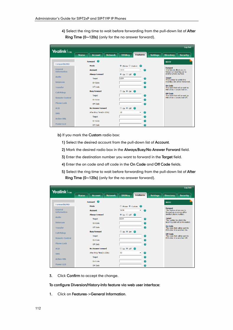
Administrator’s Guide for SIP-T2xP and SIP-T19P IP Phones
112
4) Select the ring time to wait before forwarding from the pull-down list of After
Ring Time (0~120s) (only for the no answer forward).
b) If you mark the Custom radio box:
1) Select the desired account from the pull-down list of Account.
2) Mark the desired radio box in the Always/Busy/No Answer Forward field.
3) Enter the destination number you want to forward in the Target field.
4) Enter the on code and off code in the On Code and Off Code fields.
5) Select the ring time to wait before forwarding from the pull-down list of After
Ring Time (0~120s) (only for the no answer forward).
3. Click Confirm to accept the change.
To configure Diversion/History-Info feature via web user interface:
1. Click on Features->General Information.
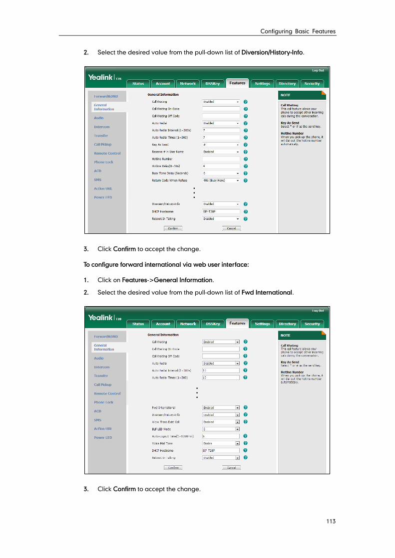
Configuring Basic Features
113
2. Select the desired value from the pull-down list of Diversion/History-Info.
3. Click Confirm to accept the change.
To configure forward international via web user interface:
1. Click on Features->General Information.
2. Select the desired value from the pull-down list of Fwd International.
3. Click Confirm to accept the change.
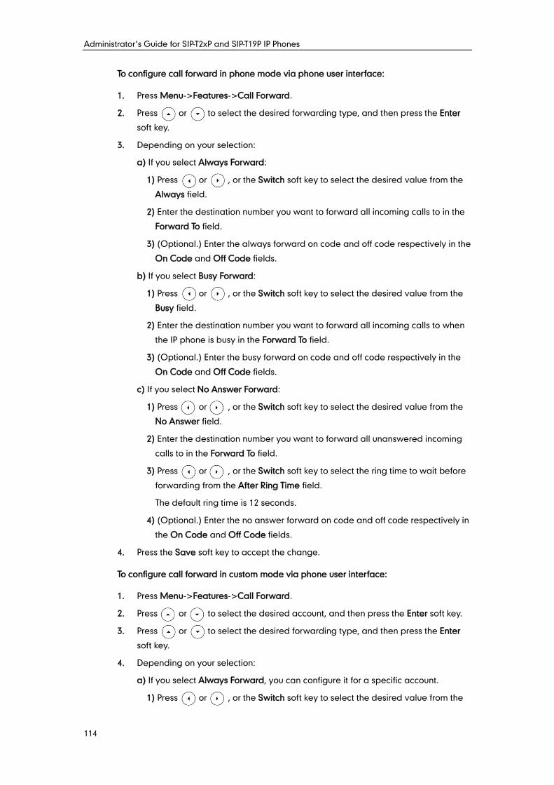
Administrator’s Guide for SIP-T2xP and SIP-T19P IP Phones
114
To configure call forward in phone mode via phone user interface:
1. Press Menu->Features->Call Forward.
2. Press or to select the desired forwarding type, and then press the Enter
soft key.
3. Depending on your selection:
a) If you select Always Forward:
1) Press or , or the Switch soft key to select the desired value from the
Always field.
2) Enter the destination number you want to forward all incoming calls to in the
Forward To field.
3) (Optional.) Enter the always forward on code and off code respectively in the
On Code and Off Code fields.
b) If you select Busy Forward:
1) Press or , or the Switch soft key to select the desired value from the
Busy field.
2) Enter the destination number you want to forward all incoming calls to when
the IP phone is busy in the Forward To field.
3) (Optional.) Enter the busy forward on code and off code respectively in the
On Code and Off Code fields.
c) If you select No Answer Forward:
1) Press or , or the Switch soft key to select the desired value from the
No Answer field.
2) Enter the destination number you want to forward all unanswered incoming
calls to in the Forward To field.
3) Press or , or the Switch soft key to select the ring time to wait before
forwarding from the After Ring Time field.
The default ring time is 12 seconds.
4) (Optional.) Enter the no answer forward on code and off code respectively in
the On Code and Off Code fields.
4. Press the Save soft key to accept the change.
To configure call forward in custom mode via phone user interface:
1. Press Menu->Features->Call Forward.
2. Press or to select the desired account, and then press the Enter soft key.
3. Press or to select the desired forwarding type, and then press the Enter
soft key.
4. Depending on your selection:
a) If you select Always Forward, you can configure it for a specific account.
1) Press or , or the Switch soft key to select the desired value from the
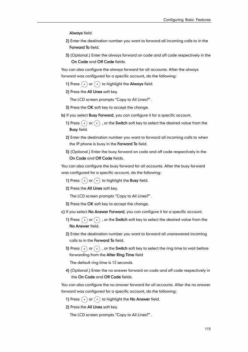
Configuring Basic Features
115
Always field.
2) Enter the destination number you want to forward all incoming calls to in the
Forward To field.
3) (Optional.) Enter the always forward on code and off code respectively in the
On Code and Off Code fields.
You can also configure the always forward for all accounts. After the always
forward was configured for a specific account, do the following:
1) Press or to highlight the Always field.
2) Press the All Lines soft key.
The LCD screen prompts “Copy to All Lines?”.
3) Press the OK soft key to accept the change.
b) If you select Busy Forward, you can configure it for a specific account.
1) Press or , or the Switch soft key to select the desired value from the
Busy field.
2) Enter the destination number you want to forward all incoming calls to when
the IP phone is busy in the Forward To field.
3) (Optional.) Enter the busy forward on code and off code respectively in the
On Code and Off Code fields.
You can also configure the busy forward for all accounts. After the busy forward
was configured for a specific account, do the following:
1) Press or to highlight the Busy field.
2) Press the All Lines soft key.
The LCD screen prompts “Copy to All Lines?”.
3) Press the OK soft key to accept the change.
c) If you select No Answer Forward, you can configure it for a specific account.
1) Press or , or the Switch soft key to select the desired value from the
No Answer field.
2) Enter the destination number you want to forward all unanswered incoming
calls to in the Forward To field.
3) Press or , or the Switch soft key to select the ring time to wait before
forwarding from the After Ring Time field
The default ring time is 12 seconds.
4) (Optional.) Enter the no answer forward on code and off code respectively in
the On Code and Off Code fields.
You can also configure the no answer forward for all accounts. After the no answer
forward was configured for a specific account, do the following:
1) Press or to highlight the No Answer field.
2) Press the All Lines soft key.
The LCD screen prompts “Copy to All Lines?”.
Administrator’s Guide for SIP-T2xP and SIP-T19P IP Phones
116
3) Press the OK soft key to accept the change.
5. Press the Save soft key to accept the change.
Call transfer enables IP phones to transfer an existing call to another party. IP phones
support call transfer using the REFER method specified in RFC 3515 and offer three types
of transfer:
Blind Transfer -- Transfer a call directly to another party without consulting. Blind
transfer is implemented by a simple REFER method without Replaces in the Refer-To
header.
Semi-attended Transfer -- Transfer a call after hearing the ringback tone.
Semi-attended transfer is implemented by a REFER method with Replaces in the
Refer-To header.
Attended Transfer -- Transfer a call with prior consulting. Attended transfer is
implemented by a REFER method with Replaces in the Refer-To header.
Normally, call transfer is completed by pressing the transfer key. Blind transfer on hook
and attended transfer on hook features allow the IP phone to complete the transfer
through on-hook.
When a user performs a semi-attended transfer, semi-attended transfer feature
determines whether to display the prompt "n New Missed Call(s)" ("n" indicates the
number of the missed calls) on the destination party’s phone LCD screen.
Procedure
Call transfer can be configured using the configuration files or locally.
Configuration File <y0000000000xx>.cfg
Specify whether to complete the
transfer through on-hook.
Configure semi-attended transfer
feature.
For more information, refer to Call
Transfer on page 336.
Local Web User Interface
Specify whether to complete the
transfer through on-hook.
Configure semi-attended transfer
feature.
Navigate to:
http://<phoneIPAddress>/servlet
?p=features-transfer&q=load
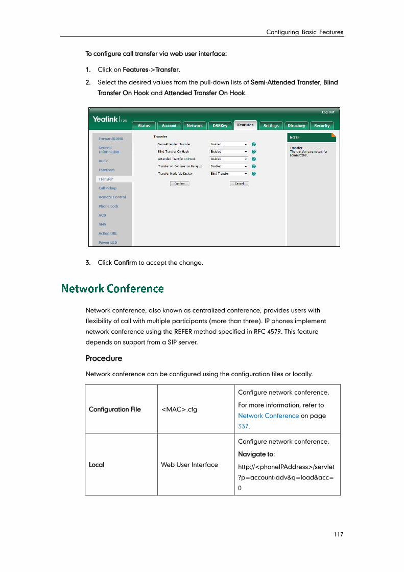
Configuring Basic Features
117
To configure call transfer via web user interface:
1. Click on Features->Transfer.
2. Select the desired values from the pull-down lists of Semi-Attended Transfer, Blind
Transfer On Hook and Attended Transfer On Hook.
3. Click Confirm to accept the change.
Network conference, also known as centralized conference, provides users with
flexibility of call with multiple participants (more than three). IP phones implement
network conference using the REFER method specified in RFC 4579. This feature
depends on support from a SIP server.
Procedure
Network conference can be configured using the configuration files or locally.
Configuration File <MAC>.cfg
Configure network conference.
For more information, refer to
Network Conference on page
337.
Local Web User Interface
Configure network conference.
Navigate to:
http://<phoneIPAddress>/servlet
?p=account-adv&q=load&acc=
0
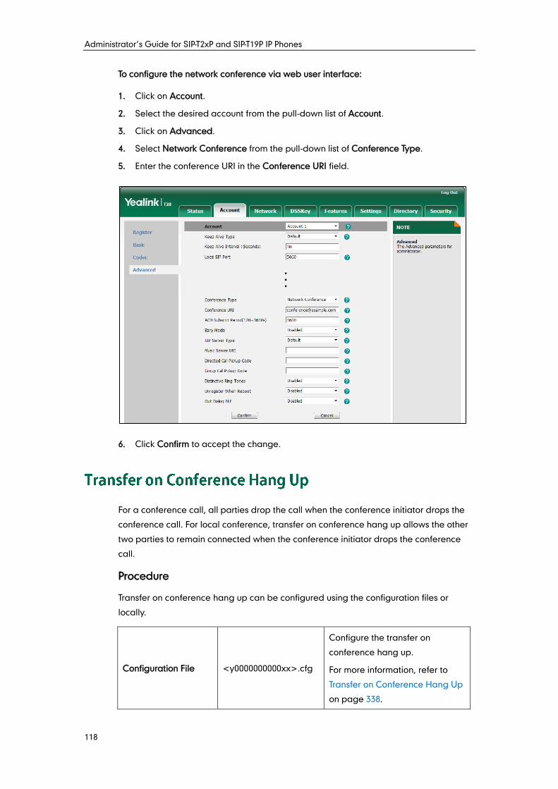
Administrator’s Guide for SIP-T2xP and SIP-T19P IP Phones
118
To configure the network conference via web user interface:
1. Click on Account.
2. Select the desired account from the pull-down list of Account.
3. Click on Advanced.
4. Select Network Conference from the pull-down list of Conference Type.
5. Enter the conference URI in the Conference URI field.
6. Click Confirm to accept the change.
For a conference call, all parties drop the call when the conference initiator drops the
conference call. For local conference, transfer on conference hang up allows the other
two parties to remain connected when the conference initiator drops the conference
call.
Procedure
Transfer on conference hang up can be configured using the configuration files or
locally.
Configuration File <y0000000000xx>.cfg
Configure the transfer on
conference hang up.
For more information, refer to
Transfer on Conference Hang Up
on page 338.
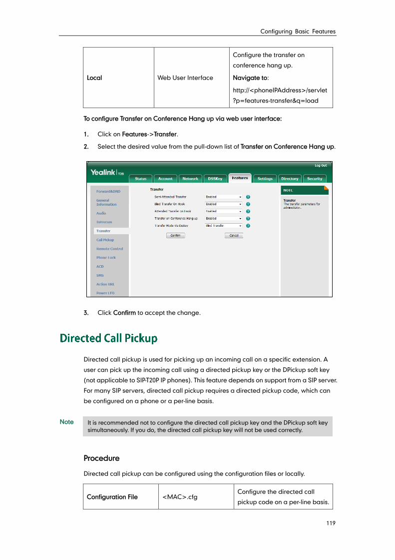
Configuring Basic Features
119
Local Web User Interface
Configure the transfer on
conference hang up.
Navigate to:
http://<phoneIPAddress>/servlet
?p=features-transfer&q=load
To configure Transfer on Conference Hang up via web user interface:
1. Click on Features->Transfer.
2. Select the desired value from the pull-down list of Transfer on Conference Hang up.
3. Click Confirm to accept the change.
Directed call pickup is used for picking up an incoming call on a specific extension. A
user can pick up the incoming call using a directed pickup key or the DPickup soft key
(not applicable to SIP-T20P IP phones). This feature depends on support from a SIP server.
For many SIP servers, directed call pickup requires a directed pickup code, which can
be configured on a phone or a per-line basis.
Note
Procedure
Directed call pickup can be configured using the configuration files or locally.
Configuration File <MAC>.cfg Configure the directed call
pickup code on a per-line basis.
It is recommended not to configure the directed call pickup key and the DPickup soft key
simultaneously. If you do, the directed call pickup key will not be used correctly.
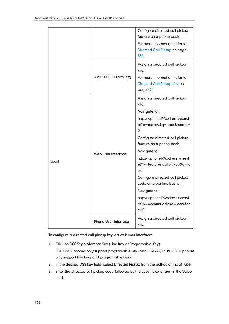
Administrator’s Guide for SIP-T2xP and SIP-T19P IP Phones
120
Configure directed call pickup
feature on a phone basis.
For more information, refer to
Directed Call Pickup on page
338.
<y0000000000xx>.cfg
Assign a directed call pickup
key.
For more information, refer to
Directed Call Pickup Key on
page 421.
Local
Web User Interface
Assign a directed call pickup
key.
Navigate to:
http://<phoneIPAddress>/servl
et?p=dsskey&q=load&model=
0
Configure directed call pickup
feature on a phone basis.
Navigate to:
http://<phoneIPAddress>/servl
et?p=features-callpickup&q=lo
ad
Configure directed call pickup
code on a per-line basis.
Navigate to:
http://<phoneIPAddress>/servl
et?p=account-adv&q=load&ac
c=0
Phone User Interface Assign a directed call pickup
key.
To configure a directed call pickup key via web user interface:
1. Click on DSSKey->Memory Key (Line Key or Programable Key).
SIP-T19P IP phones only support programable keys and SIP-T22P/T21P/T20P IP phones
only support line keys and programable keys.
2. In the desired DSS key field, select Directed Pickup from the pull-down list of Type.
3. Enter the directed call pickup code followed by the specific extension in the Value
field.
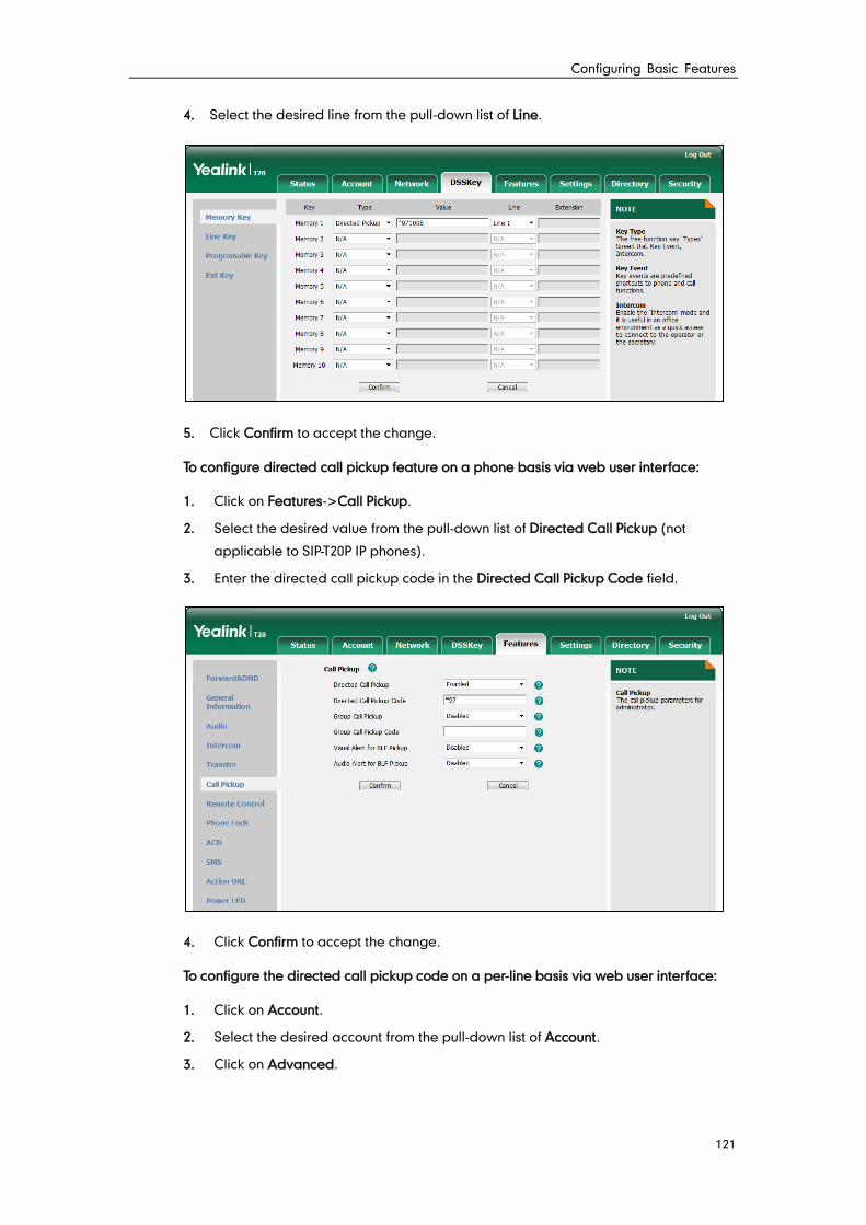
Configuring Basic Features
121
4. Select the desired line from the pull-down list of Line.
5. Click Confirm to accept the change.
To configure directed call pickup feature on a phone basis via web user interface:
1. Click on Features->Call Pickup.
2. Select the desired value from the pull-down list of Directed Call Pickup (not
applicable to SIP-T20P IP phones).
3. Enter the directed call pickup code in the Directed Call Pickup Code field.
4. Click Confirm to accept the change.
To configure the directed call pickup code on a per-line basis via web user interface:
1. Click on Account.
2. Select the desired account from the pull-down list of Account.
3. Click on Advanced.
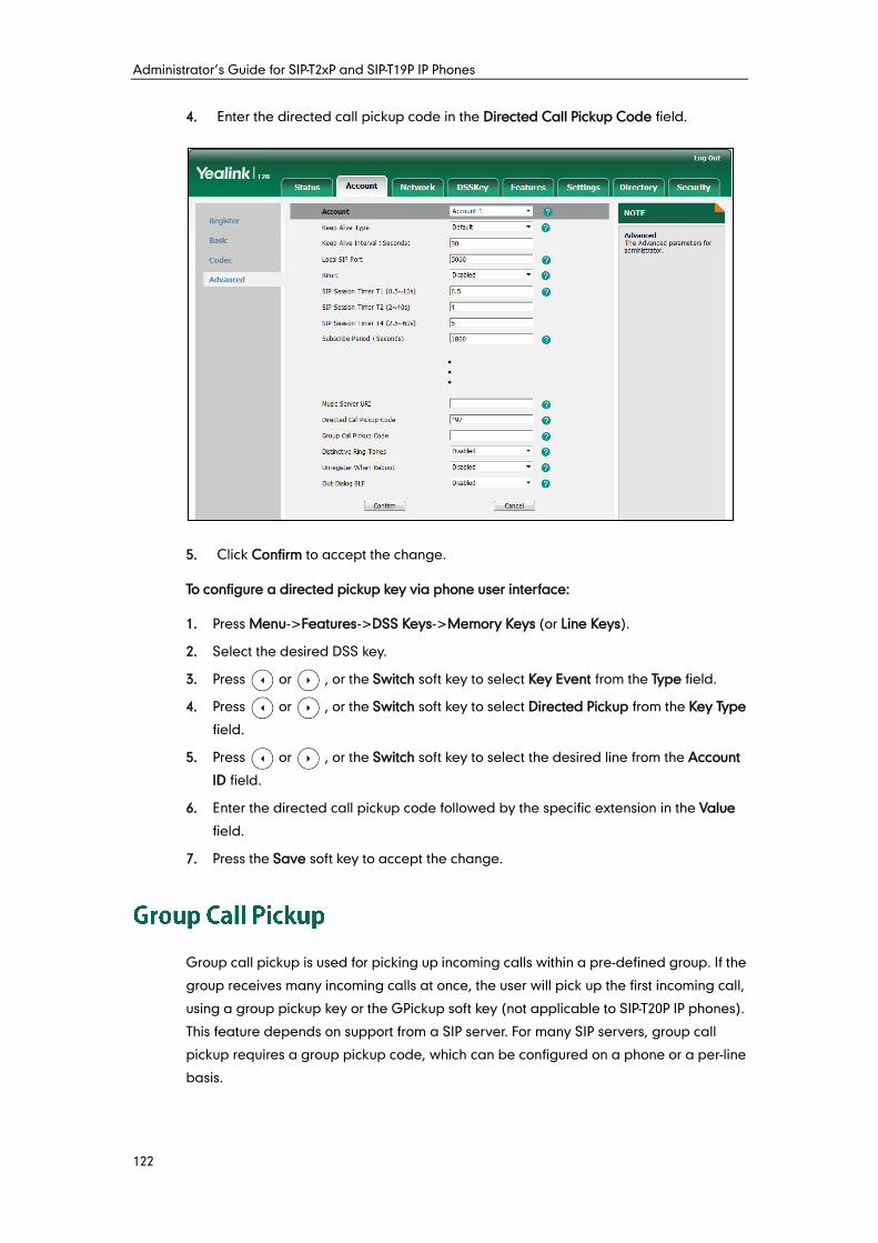
Administrator’s Guide for SIP-T2xP and SIP-T19P IP Phones
122
4. Enter the directed call pickup code in the Directed Call Pickup Code field.
5. Click Confirm to accept the change.
To configure a directed pickup key via phone user interface:
1. Press Menu->Features->DSS Keys->Memory Keys (or Line Keys).
2. Select the desired DSS key.
3. Press or , or the Switch soft key to select Key Event from the Type field.
4. Press or , or the Switch soft key to select Directed Pickup from the Key Type
field.
5. Press or , or the Switch soft key to select the desired line from the Account
ID field.
6. Enter the directed call pickup code followed by the specific extension in the Value
field.
7. Press the Save soft key to accept the change.
Group call pickup is used for picking up incoming calls within a pre-defined group. If the
group receives many incoming calls at once, the user will pick up the first incoming call,
using a group pickup key or the GPickup soft key (not applicable to SIP-T20P IP phones).
This feature depends on support from a SIP server. For many SIP servers, group call
pickup requires a group pickup code, which can be configured on a phone or a per-line
basis.
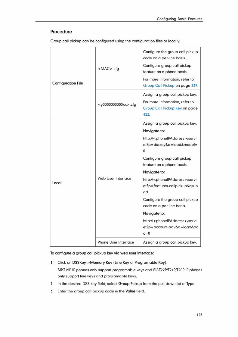
Configuring Basic Features
123
Procedure
Group call pickup can be configured using the configuration files or locally.
Configuration File
<MAC>.cfg
Configure the group call pickup
code on a per-line basis.
Configure group call pickup
feature on a phone basis.
For more information, refer to
Group Call Pickup on page 339.
<y0000000000xx>.cfg
Assign a group call pickup key.
For more information, refer to
Group Call Pickup Key on page
423.
Local Web User Interface
Assign a group call pickup key.
Navigate to:
http://<phoneIPAddress>/servl
et?p=dsskey&q=load&model=
0
Configure group call pickup
feature on a phone basis.
Navigate to:
http://<phoneIPAddress>/servl
et?p=features-callpickup&q=lo
ad
Configure the group call pickup
code on a per-line basis.
Navigate to:
http://<phoneIPAddress>/servl
et?p=account-adv&q=load&ac
c=0
Phone User Interface Assign a group call pickup key.
To configure a group call pickup key via web user interface:
1. Click on DSSKey->Memory Key (Line Key or Programable Key).
SIP-T19P IP phones only support programable keys and SIP-T22P/T21P/T20P IP phones
only support line keys and programable keys.
2. In the desired DSS key field, select Group Pickup from the pull-down list of Type.
3. Enter the group call pickup code in the Value field.
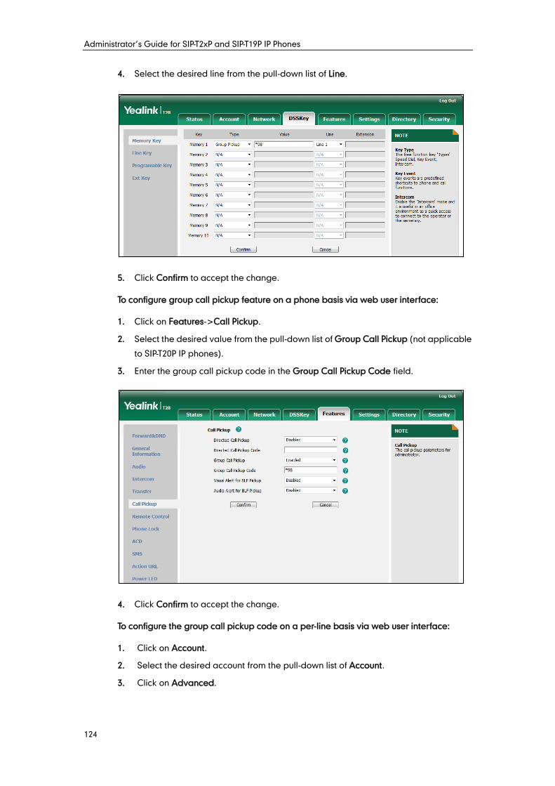
Administrator’s Guide for SIP-T2xP and SIP-T19P IP Phones
124
4. Select the desired line from the pull-down list of Line.
5. Click Confirm to accept the change.
To configure group call pickup feature on a phone basis via web user interface:
1. Click on Features->Call Pickup.
2. Select the desired value from the pull-down list of Group Call Pickup (not applicable
to SIP-T20P IP phones).
3. Enter the group call pickup code in the Group Call Pickup Code field.
4. Click Confirm to accept the change.
To configure the group call pickup code on a per-line basis via web user interface:
1. Click on Account.
2. Select the desired account from the pull-down list of Account.
3. Click on Advanced.
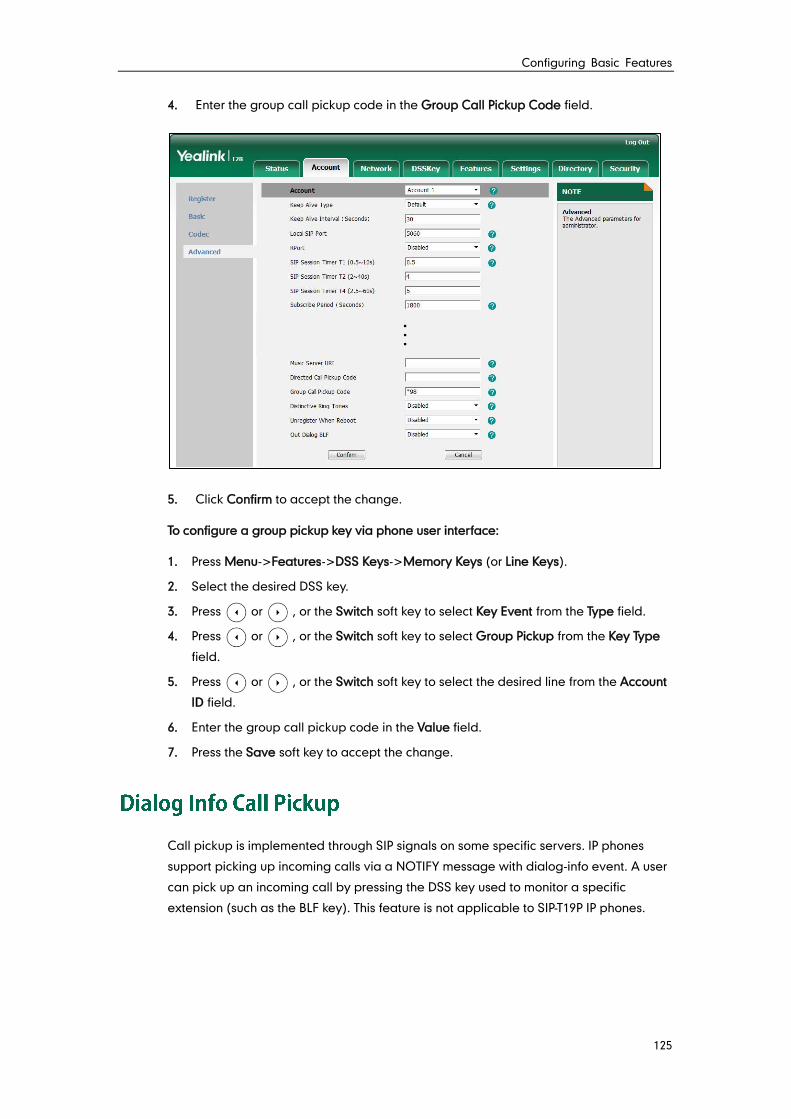
Configuring Basic Features
125
4. Enter the group call pickup code in the Group Call Pickup Code field.
5. Click Confirm to accept the change.
To configure a group pickup key via phone user interface:
1. Press Menu->Features->DSS Keys->Memory Keys (or Line Keys).
2. Select the desired DSS key.
3. Press or , or the Switch soft key to select Key Event from the Type field.
4. Press or , or the Switch soft key to select Group Pickup from the Key Type
field.
5. Press or , or the Switch soft key to select the desired line from the Account
ID field.
6. Enter the group call pickup code in the Value field.
7. Press the Save soft key to accept the change.
Call pickup is implemented through SIP signals on some specific servers. IP phones
support picking up incoming calls via a NOTIFY message with dialog-info event. A user
can pick up an incoming call by pressing the DSS key used to monitor a specific
extension (such as the BLF key). This feature is not applicable to SIP-T19P IP phones.
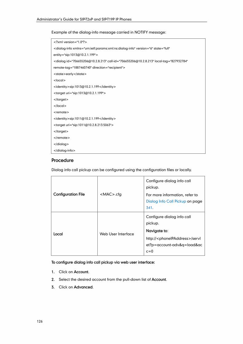
Administrator’s Guide for SIP-T2xP and SIP-T19P IP Phones
126
Example of the dialog-info message carried in NOTIFY message:
<?xml version="1.0"?>
<dialog-info xmlns="urn:ietf:params:xml:ns:dialog-info" version="6" state="full"
entity="sip:[email protected]">
<dialog id="[email protected]" call-id="[email protected]" local-tag="827932784"
remote-tag="1887460740" direction="recipient">
<state>early</state>
<local>
<identity>sip:[email protected]</identity>
<target uri="sip:[email protected]">
</target>
</local>
<remote>
<identity>sip:[email protected]</identity>
<target uri="sip:[email protected]:5063">
</target>
</remote>
</dialog>
</dialog-info>
Procedure
Dialog info call pickup can be configured using the configuration files or locally.
Configuration File <MAC>.cfg
Configure dialog info call
pickup.
For more information, refer to
Dialog Info Call Pickup on page
341.
Local Web User Interface
Configure dialog info call
pickup.
Navigate to:
http://<phoneIPAddress>/servl
et?p=account-adv&q=load&ac
c=0
To configure dialog info call pickup via web user interface:
1. Click on Account.
2. Select the desired account from the pull-down list of Account.
3. Click on Advanced.
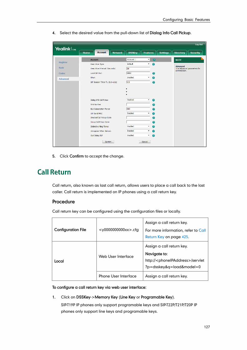
Configuring Basic Features
127
4. Select the desired value from the pull-down list of Dialog Info Call Pickup.
5. Click Confirm to accept the change.
Call return, also known as last call return, allows users to place a call back to the last
caller. Call return is implemented on IP phones using a call return key.
Procedure
Call return key can be configured using the configuration files or locally.
Configuration File <y0000000000xx>.cfg
Assign a call return key.
For more information, refer to Call
Return Key on page 425.
Local Web User Interface
Assign a call return key.
Navigate to:
http://<phoneIPAddress>/servlet
?p=dsskey&q=load&model=0
Phone User Interface Assign a call return key.
To configure a call return key via web user interface:
1. Click on DSSKey->Memory Key (Line Key or Programable Key).
SIP-T19P IP phones only support programable keys and SIP-T22P/T21P/T20P IP
phones only support line keys and programable keys.
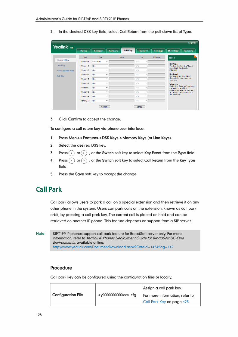
Administrator’s Guide for SIP-T2xP and SIP-T19P IP Phones
128
2. In the desired DSS key field, select Call Return from the pull-down list of Type.
3. Click Confirm to accept the change.
To configure a call return key via phone user interface:
1. Press Menu->Features->DSS Keys->Memory Keys (or Line Keys).
2. Select the desired DSS key.
3. Press or , or the Switch soft key to select Key Event from the Type field.
4. Press or , or the Switch soft key to select Call Return from the Key Type
field.
5. Press the Save soft key to accept the change.
Call park allows users to park a call on a special extension and then retrieve it on any
other phone in the system. Users can park calls on the extension, known as call park
orbit, by pressing a call park key. The current call is placed on hold and can be
retrieved on another IP phone. This feature depends on support from a SIP server.
Note
Procedure
Call park key can be configured using the configuration files or locally.
Configuration File <y0000000000xx>.cfg
Assign a call park key.
For more information, refer to
Call Park Key on page 425.
SIP-T19P IP phones support call park feature for BroadSoft server only. For more
information, refer to Yealink IP Phones Deployment Guide for BroadSoft UC-One Environments, available online:
http://www.yealink.com/DocumentDownload.aspx?CateId=142&flag=142.
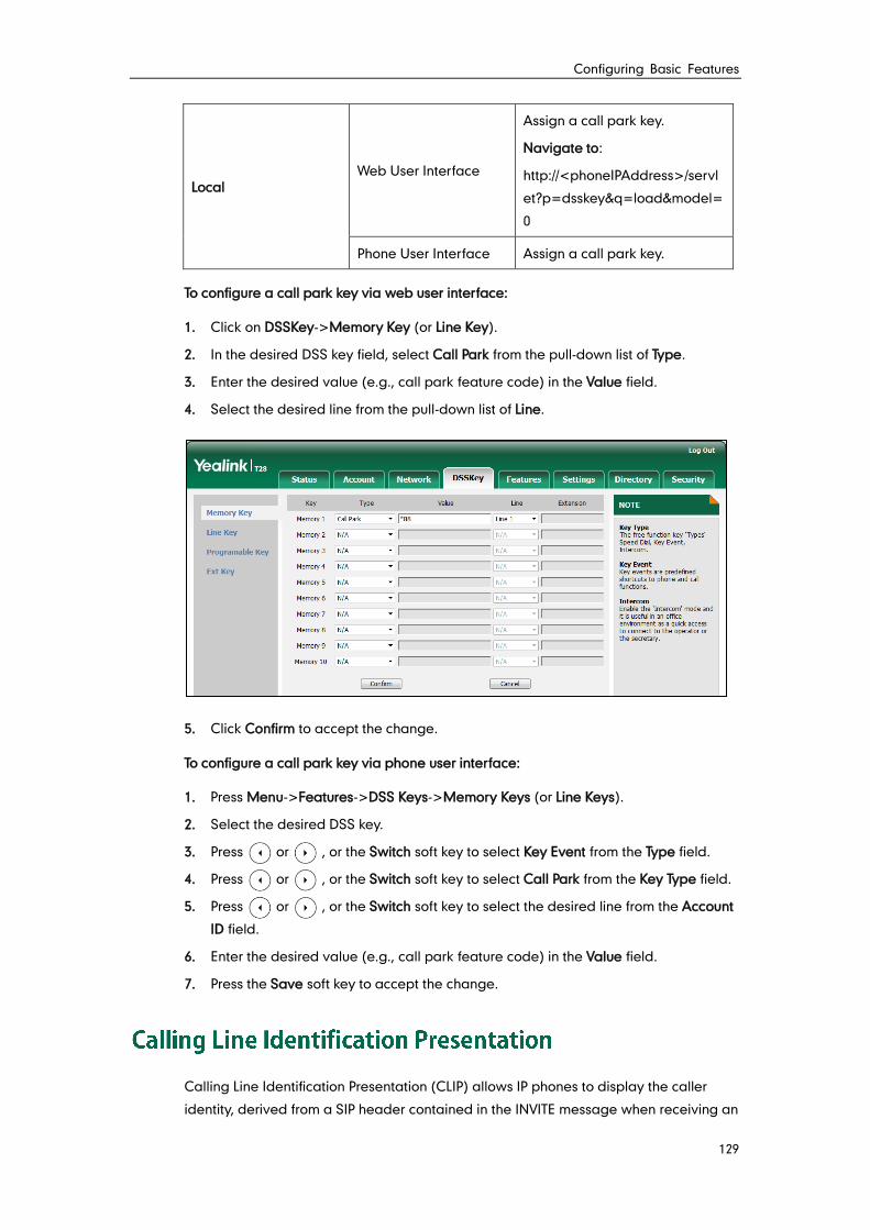
Configuring Basic Features
129
Local Web User Interface
Assign a call park key.
Navigate to:
http://<phoneIPAddress>/servl
et?p=dsskey&q=load&model=
0
Phone User Interface Assign a call park key.
To configure a call park key via web user interface:
1. Click on DSSKey->Memory Key (or Line Key).
2. In the desired DSS key field, select Call Park from the pull-down list of Type.
3. Enter the desired value (e.g., call park feature code) in the Value field.
4. Select the desired line from the pull-down list of Line.
5. Click Confirm to accept the change.
To configure a call park key via phone user interface:
1. Press Menu->Features->DSS Keys->Memory Keys (or Line Keys).
2. Select the desired DSS key.
3. Press or , or the Switch soft key to select Key Event from the Type field.
4. Press or , or the Switch soft key to select Call Park from the Key Type field.
5. Press or , or the Switch soft key to select the desired line from the Account
ID field.
6. Enter the desired value (e.g., call park feature code) in the Value field.
7. Press the Save soft key to accept the change.
Calling Line Identification Presentation (CLIP) allows IP phones to display the caller
identity, derived from a SIP header contained in the INVITE message when receiving an
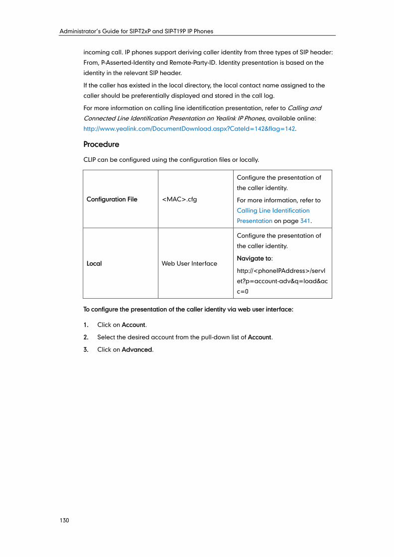
Administrator’s Guide for SIP-T2xP and SIP-T19P IP Phones
130
incoming call. IP phones support deriving caller identity from three types of SIP header:
From, P-Asserted-Identity and Remote-Party-ID. Identity presentation is based on the
identity in the relevant SIP header.
If the caller has existed in the local directory, the local contact name assigned to the
caller should be preferentially displayed and stored in the call log.
For more information on calling line identification presentation, refer to Calling and
Connected Line Identification Presentation on Yealink IP Phones, available online:
http://www.yealink.com/DocumentDownload.aspx?CateId=142&flag=142.
Procedure
CLIP can be configured using the configuration files or locally.
Configuration File <MAC>.cfg
Configure the presentation of
the caller identity.
For more information, refer to
Calling Line Identification
Presentation on page 341.
Local Web User Interface
Configure the presentation of
the caller identity.
Navigate to:
http://<phoneIPAddress>/servl
et?p=account-adv&q=load&ac
c=0
To configure the presentation of the caller identity via web user interface:
1. Click on Account.
2. Select the desired account from the pull-down list of Account.
3. Click on Advanced.
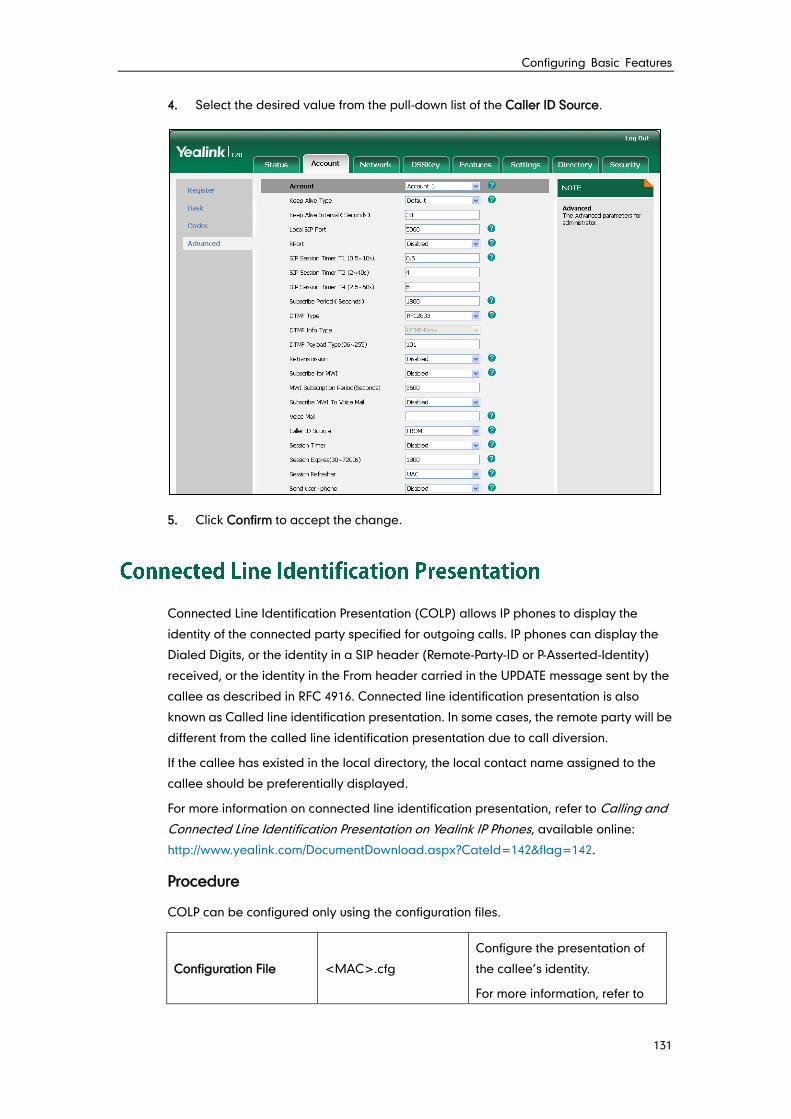
Configuring Basic Features
131
4. Select the desired value from the pull-down list of the Caller ID Source.
5. Click Confirm to accept the change.
Connected Line Identification Presentation (COLP) allows IP phones to display the
identity of the connected party specified for outgoing calls. IP phones can display the
Dialed Digits, or the identity in a SIP header (Remote-Party-ID or P-Asserted-Identity)
received, or the identity in the From header carried in the UPDATE message sent by the
callee as described in RFC 4916. Connected line identification presentation is also
known as Called line identification presentation. In some cases, the remote party will be
different from the called line identification presentation due to call diversion.
If the callee has existed in the local directory, the local contact name assigned to the
callee should be preferentially displayed.
For more information on connected line identification presentation, refer to Calling and
Connected Line Identification Presentation on Yealink IP Phones, available online:
http://www.yealink.com/DocumentDownload.aspx?CateId=142&flag=142.
Procedure
COLP can be configured only using the configuration files.
Configuration File <MAC>.cfg
Configure the presentation of
the callee’s identity.
For more information, refer to
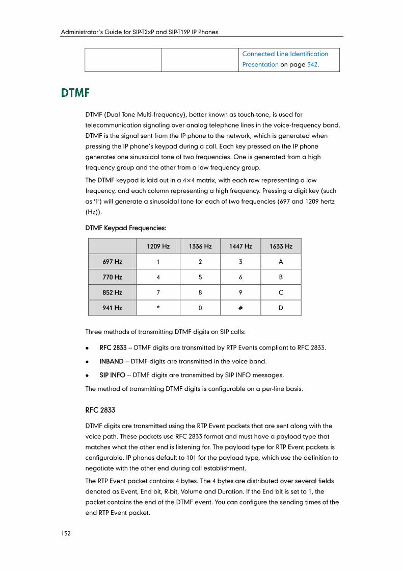
Administrator’s Guide for SIP-T2xP and SIP-T19P IP Phones
132
Connected Line Identification
Presentation on page 342.
DTMF (Dual Tone Multi-frequency), better known as touch-tone, is used for
telecommunication signaling over analog telephone lines in the voice-frequency band.
DTMF is the signal sent from the IP phone to the network, which is generated when
pressing the IP phone’s keypad during a call. Each key pressed on the IP phone
generates one sinusoidal tone of two frequencies. One is generated from a high
frequency group and the other from a low frequency group.
The DTMF keypad is laid out in a 4× 4 matrix, with each row representing a low
frequency, and each column representing a high frequency. Pressing a digit key (such
as '1') will generate a sinusoidal tone for each of two frequencies (697 and 1209 hertz
(Hz)).
DTMF Keypad Frequencies:
1209 Hz 1336 Hz 1447 Hz 1633 Hz
697 Hz 1 2 3 A
770 Hz 4 5 6 B
852 Hz 7 8 9 C
941 Hz * 0 # D
Three methods of transmitting DTMF digits on SIP calls:
RFC 2833 -- DTMF digits are transmitted by RTP Events compliant to RFC 2833.
INBAND -- DTMF digits are transmitted in the voice band.
SIP INFO -- DTMF digits are transmitted by SIP INFO messages.
The method of transmitting DTMF digits is configurable on a per-line basis.
RFC 2833
DTMF digits are transmitted using the RTP Event packets that are sent along with the
voice path. These packets use RFC 2833 format and must have a payload type that
matches what the other end is listening for. The payload type for RTP Event packets is
configurable. IP phones default to 101 for the payload type, which use the definition to
negotiate with the other end during call establishment.
The RTP Event packet contains 4 bytes. The 4 bytes are distributed over several fields
denoted as Event, End bit, R-bit, Volume and Duration. If the End bit is set to 1, the
packet contains the end of the DTMF event. You can configure the sending times of the
end RTP Event packet.
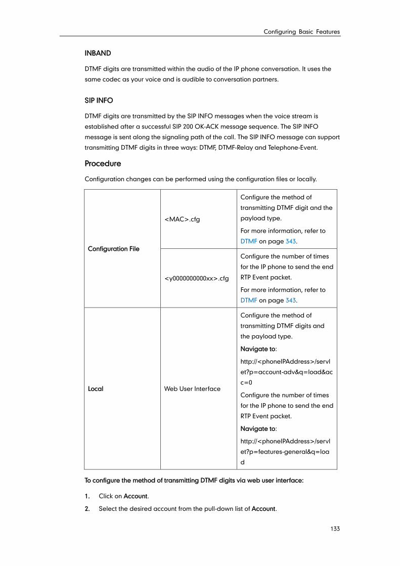
Configuring Basic Features
133
INBAND
DTMF digits are transmitted within the audio of the IP phone conversation. It uses the
same codec as your voice and is audible to conversation partners.
SIP INFO
DTMF digits are transmitted by the SIP INFO messages when the voice stream is
established after a successful SIP 200 OK-ACK message sequence. The SIP INFO
message is sent along the signaling path of the call. The SIP INFO message can support
transmitting DTMF digits in three ways: DTMF, DTMF-Relay and Telephone-Event.
Procedure
Configuration changes can be performed using the configuration files or locally.
Configuration File
<MAC>.cfg
Configure the method of
transmitting DTMF digit and the
payload type.
For more information, refer to
DTMF on page 343.
<y0000000000xx>.cfg
Configure the number of times
for the IP phone to send the end
RTP Event packet.
For more information, refer to
DTMF on page 343.
Local Web User Interface
Configure the method of
transmitting DTMF digits and
the payload type.
Navigate to:
http://<phoneIPAddress>/servl
et?p=account-adv&q=load&ac
c=0
Configure the number of times
for the IP phone to send the end
RTP Event packet.
Navigate to:
http://<phoneIPAddress>/servl
et?p=features-general&q=loa
d
To configure the method of transmitting DTMF digits via web user interface:
1. Click on Account.
2. Select the desired account from the pull-down list of Account.

Administrator’s Guide for SIP-T2xP and SIP-T19P IP Phones
134
3. Click on Advanced.
4. Select the desired value from the pull-down list of DTMF Type.
5. If SIP INFO or AUTO or SIP INFO is selected, select the desired value from the
pull-down list of DTMF Info Type.
6. Enter the desired value in the DTMF Payload Type (96~127) field.
7. Click Confirm to accept the change.
To configure the number of times to send the end RTP Event packet via web user
interface:
1. Click on Features->General Information.
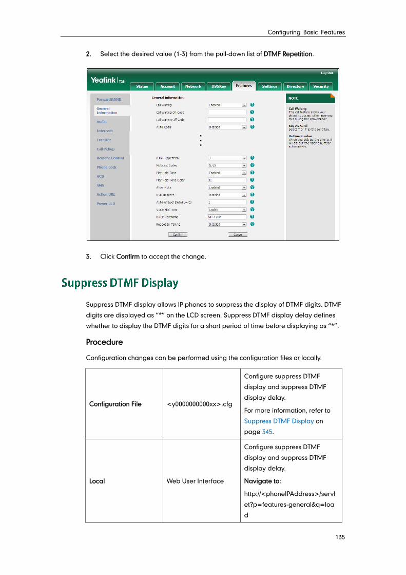
Configuring Basic Features
135
2. Select the desired value (1-3) from the pull-down list of DTMF Repetition.
3. Click Confirm to accept the change.
Suppress DTMF display allows IP phones to suppress the display of DTMF digits. DTMF
digits are displayed as “*” on the LCD screen. Suppress DTMF display delay defines
whether to display the DTMF digits for a short period of time before displaying as “*”.
Procedure
Configuration changes can be performed using the configuration files or locally.
Configuration File <y0000000000xx>.cfg
Configure suppress DTMF
display and suppress DTMF
display delay.
For more information, refer to
Suppress DTMF Display on
page 345.
Local Web User Interface
Configure suppress DTMF
display and suppress DTMF
display delay.
Navigate to:
http://<phoneIPAddress>/servl
et?p=features-general&q=loa
d
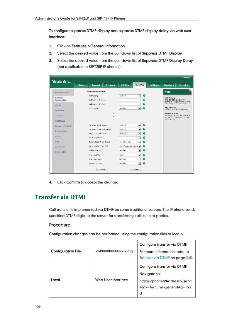
Administrator’s Guide for SIP-T2xP and SIP-T19P IP Phones
136
To configure suppress DTMF display and suppress DTMF display delay via web user
interface:
1. Click on Features->General Information.
2. Select the desired value from the pull-down list of Suppress DTMF Display.
3. Select the desired value from the pull-down list of Suppress DTMF Display Delay
(not applicable to SIP-T20P IP phones).
4. Click Confirm to accept the change.
Call transfer is implemented via DTMF on some traditional servers. The IP phone sends
specified DTMF digits to the server for transferring calls to third parties.
Procedure
Configuration changes can be performed using the configuration files or locally.
Configuration File <y0000000000xx>.cfg
Configure transfer via DTMF.
For more information, refer to
Transfer via DTMF on page 345.
Local Web User Interface
Configure transfer via DTMF.
Navigate to:
http://<phoneIPAddress>/servl
et?p=features-general&q=loa
d
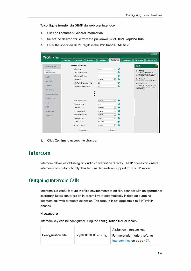
Configuring Basic Features
137
To configure transfer via DTMF via web user interface:
1. Click on Features->General Information.
2. Select the desired value from the pull-down list of DTMF Replace Tran.
3. Enter the specified DTMF digits in the Tran Send DTMF field.
4. Click Confirm to accept the change.
Intercom allows establishing an audio conversation directly. The IP phone can answer
intercom calls automatically. This feature depends on support from a SIP server.
Intercom is a useful feature in office environments to quickly connect with an operator or
secretary. Users can press an intercom key to automatically initiate an outgoing
intercom call with a remote extension. This feature is not applicable to SIP-T19P IP
phones.
Procedure
Intercom key can be configured using the configuration files or locally.
Configuration File <y0000000000xx>.cfg
Assign an intercom key.
For more information, refer to
Intercom Key on page 427.
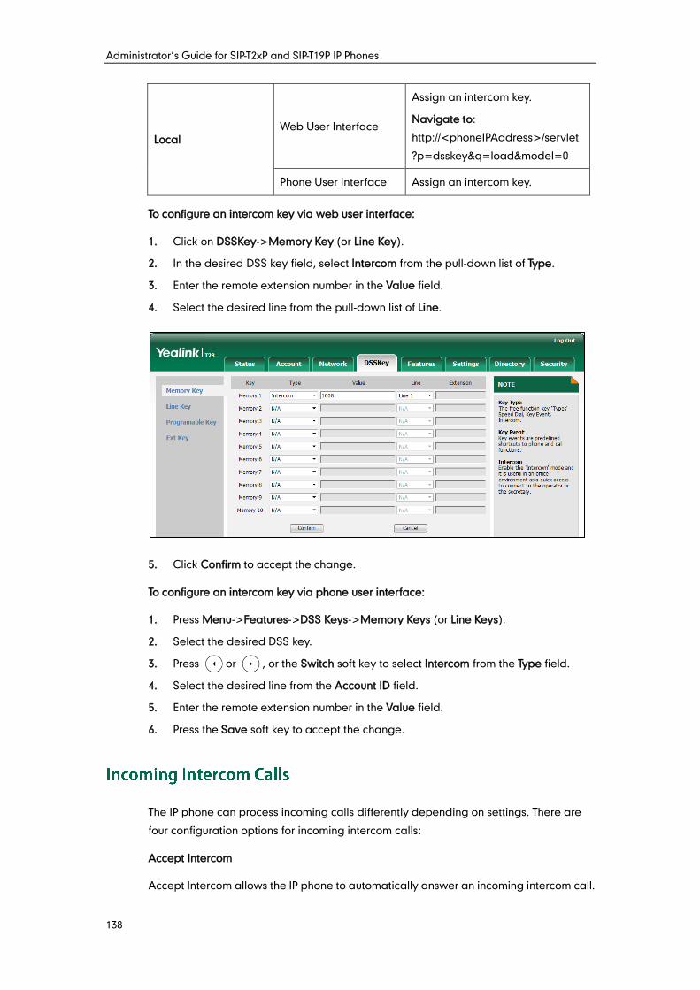
Administrator’s Guide for SIP-T2xP and SIP-T19P IP Phones
138
Local Web User Interface
Assign an intercom key.
Navigate to:
http://<phoneIPAddress>/servlet
?p=dsskey&q=load&model=0
Phone User Interface Assign an intercom key.
To configure an intercom key via web user interface:
1. Click on DSSKey->Memory Key (or Line Key).
2. In the desired DSS key field, select Intercom from the pull-down list of Type.
3. Enter the remote extension number in the Value field.
4. Select the desired line from the pull-down list of Line.
5. Click Confirm to accept the change.
To configure an intercom key via phone user interface:
1. Press Menu->Features->DSS Keys->Memory Keys (or Line Keys).
2. Select the desired DSS key.
3. Press or , or the Switch soft key to select Intercom from the Type field.
4. Select the desired line from the Account ID field.
5. Enter the remote extension number in the Value field.
6. Press the Save soft key to accept the change.
The IP phone can process incoming calls differently depending on settings. There are
four configuration options for incoming intercom calls:
Accept Intercom
Accept Intercom allows the IP phone to automatically answer an incoming intercom call.
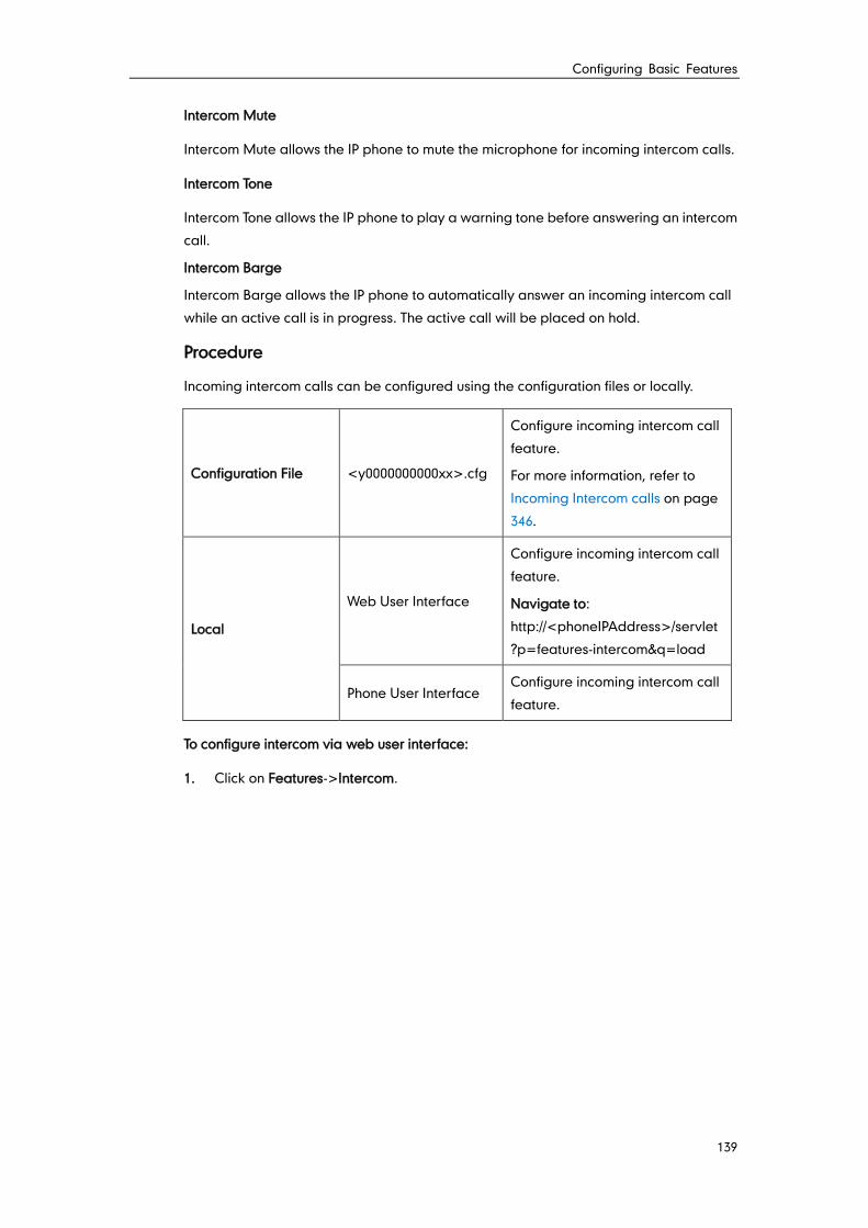
Configuring Basic Features
139
Intercom Mute
Intercom Mute allows the IP phone to mute the microphone for incoming intercom calls.
Intercom Tone
Intercom Tone allows the IP phone to play a warning tone before answering an intercom
call.
Intercom Barge
Intercom Barge allows the IP phone to automatically answer an incoming intercom call
while an active call is in progress. The active call will be placed on hold.
Procedure
Incoming intercom calls can be configured using the configuration files or locally.
Configuration File <y0000000000xx>.cfg
Configure incoming intercom call
feature.
For more information, refer to
Incoming Intercom calls on page
346.
Local
Web User Interface
Configure incoming intercom call
feature.
Navigate to:
http://<phoneIPAddress>/servlet
?p=features-intercom&q=load
Phone User Interface Configure incoming intercom call
feature.
To configure intercom via web user interface:
1. Click on Features->Intercom.
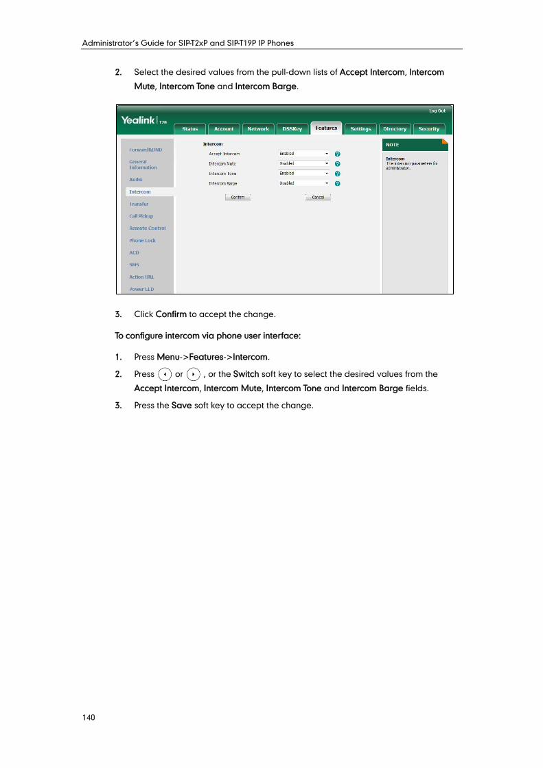
Administrator’s Guide for SIP-T2xP and SIP-T19P IP Phones
140
2. Select the desired values from the pull-down lists of Accept Intercom, Intercom
Mute, Intercom Tone and Intercom Barge.
3. Click Confirm to accept the change.
To configure intercom via phone user interface:
1. Press Menu->Features->Intercom.
2. Press or , or the Switch soft key to select the desired values from the
Accept Intercom, Intercom Mute, Intercom Tone and Intercom Barge fields.
3. Press the Save soft key to accept the change.
Configuring Advanced Features
141
This chapter provides information for making configuration changes for the following
advanced features:
Distinctive Ring Tones
Tones
Remote Phone Book
LDAP
Busy Lamp Field
Automatic Call Distribution
Message Waiting Indicator
Multicast Paging
Call Recording
Hot Desking
Action URL
Action URI
Server Redundancy
LLDP
VLAN
VPN
Quality of Service
Network Address Translation
802.1X Authentication
TR-069 Device Management
IPv6 Support
Distinctive ring tones allows certain incoming calls to trigger IP phones to play distinctive
ring tones. The IP phone inspects the INVITE request for an "Alert-Info" header when
receiving an incoming call. If the INVITE request contains an "Alert-Info" header, the IP
phone strips out the URL and keyword parameter and maps them to the appropriate
ring tone.
Note If the caller has existed in the local directory, the ring tone assigned to the caller should be preferentially played.
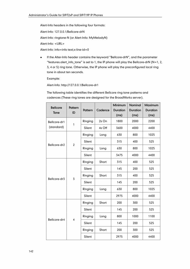
Administrator’s Guide for SIP-T2xP and SIP-T19P IP Phones
142
Alert-Info headers in the following four formats:
Alert-Info: 127.0.0.1/Bellcore-drN
Alert-Info: ringtone-N (or Alert-Info: MyMelodyN)
Alert-Info: <URL>
Alert-Info: info=info text;x-line-id=0
If the Alter-Info header contains the keyword “Bellcore-drN”, and the parameter
“features.alert_info_tone” is set to 1, the IP phone will play the Bellcore-drN (N=1, 2,
3, 4 or 5) ring tone. Otherwise, the IP phone will play the preconfigured local ring
tone in about ten seconds.
Example:
Alert-Info: http://127.0.0.1/Bellcore-dr1
The following table identifies the different Bellcore ring tone patterns and
cadences (These ring tones are designed for the BroadWorks server).
Bellcore
Tone
Pattern
ID Pattern Cadence
Minimum
Duration
(ms)
Nominal
Duration
(ms)
Maximum
Duration
(ms)
Bellcore-dr1
(standard) 1
Ringing 2s On 1800 2000 2200
Silent 4s Off 3600 4000 4400
Bellcore-dr2 2
Ringing Long 630 800 1025
Silent 315 400 525
Ringing Long 630 800 1025
Silent 3475 4000 4400
Bellcore-dr3 3
Ringing Short 315 400 525
Silent 145 200 525
Ringing Short 315 400 525
Silent 145 200 525
Ringing Long 630 800 1025
Silent 2975 4000 4400
Bellcore-dr4 4
Ringing Short 200 300 525
Silent 145 200 525
Ringing Long 800 1000 1100
Silent 145 200 525
Ringing Short 200 300 525
Silent 2975 4000 4400
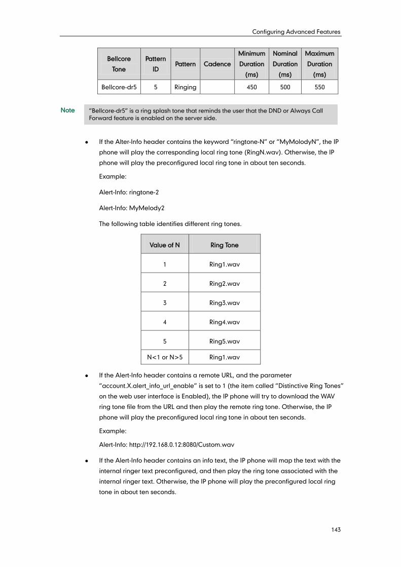
Configuring Advanced Features
143
Bellcore
Tone
Pattern
ID Pattern Cadence
Minimum
Duration
(ms)
Nominal
Duration
(ms)
Maximum
Duration
(ms)
Bellcore-dr5 5 Ringing 450 500 550
Note
If the Alter-Info header contains the keyword “ringtone-N” or “MyMolodyN”, the IP
phone will play the corresponding local ring tone (RingN.wav). Otherwise, the IP
phone will play the preconfigured local ring tone in about ten seconds.
Example:
Alert-Info: ringtone-2
Alert-Info: MyMelody2
The following table identifies different ring tones.
Value of N Ring Tone
1 Ring1.wav
2 Ring2.wav
3 Ring3.wav
4 Ring4.wav
5 Ring5.wav
N<1 or N>5 Ring1.wav
If the Alert-Info header contains a remote URL, and the parameter
“account.X.alert_info_url_enable” is set to 1 (the item called “Distinctive Ring Tones”
on the web user interface is Enabled), the IP phone will try to download the WAV
ring tone file from the URL and then play the remote ring tone. Otherwise, the IP
phone will play the preconfigured local ring tone in about ten seconds.
Example:
Alert-Info: http://192.168.0.12:8080/Custom.wav
If the Alert-Info header contains an info text, the IP phone will map the text with the
internal ringer text preconfigured, and then play the ring tone associated with the
internal ringer text. Otherwise, the IP phone will play the preconfigured local ring
tone in about ten seconds.
“Bellcore-dr5” is a ring splash tone that reminds the user that the DND or Always Call
Forward feature is enabled on the server side.
Administrator’s Guide for SIP-T2xP and SIP-T19P IP Phones
144
Example:
Alert-Info: info=family;x-line-id=0
Procedure
Distinctive ring tones can be configured using the configuration files or locally.
Configuration File
<MAC>.cfg
Configure distinctive ring tones.
For more information, refer to
Distinctive Ring Tones on page
348.
<y0000000000xx>.cfg
Configure the internal ringer
text and internal ringer file.
For more information, refer to
Distinctive Ring Tones on page
348.
Local Web User Interface
Configure distinctive ring tones.
Navigate to:
http://<phoneIPAddress>/servl
et?p=account-adv&q=load&ac
c=0
Configure the internal ringer
text and internal ringer file.
Navigate to:
http://<phoneIPAddress>/servl
et?p=settings-ring&q=load
To configure distinctive ring tones via web user interface:
1. Click on Account.
2. Select the desired account from the pull-down list of Account.
3. Click on Advanced.
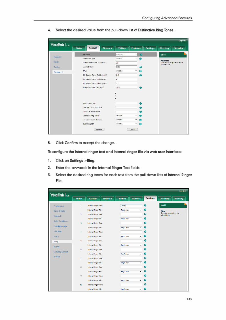
Configuring Advanced Features
145
4. Select the desired value from the pull-down list of Distinctive Ring Tones.
5. Click Confirm to accept the change.
To configure the internal ringer text and internal ringer file via web user interface:
1. Click on Settings->Ring.
2. Enter the keywords in the Internal Ringer Text fields.
3. Select the desired ring tones for each text from the pull-down lists of Internal Ringer
File.
Administrator’s Guide for SIP-T2xP and SIP-T19P IP Phones
146
4. Click Confirm to accept the change.
When receiving a message, the IP phone will play a warning tone. You can customize
tones or select specialized tone sets (vary from country to country) to indicate different
conditions of the IP phone. The default tones used on IP phones are the US tone sets.
Available tone sets for IP phones:
Australia
Austria
Brazil
Belgium
China
Czech
Denmark
Finland
France
Germany
Great Britain
Greece
Hungary
Lithuania
India
Italy
Japan
Mexico
New Zealand
Netherlands
Norway
Portugal
Spain
Switzerland
Sweden
Russia
United States
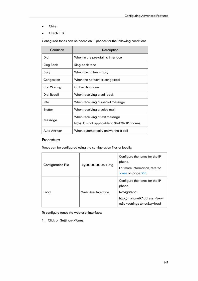
Configuring Advanced Features
147
Chile
Czech ETSI
Configured tones can be heard on IP phones for the following conditions.
Condition Description
Dial When in the pre-dialing interface
Ring Back Ring-back tone
Busy When the callee is busy
Congestion When the network is congested
Call Waiting Call waiting tone
Dial Recall When receiving a call back
Info When receiving a special message
Stutter When receiving a voice mail
Message When receiving a text message
Note: It is not applicable to SIP-T20P IP phones.
Auto Answer When automatically answering a call
Procedure
Tones can be configured using the configuration files or locally.
Configuration File <y0000000000xx>.cfg
Configure the tones for the IP
phone.
For more information, refer to
Tones on page 350.
Local Web User Interface
Configure the tones for the IP
phone.
Navigate to:
http://<phoneIPAddress>/servl
et?p=settings-tones&q=load
To configure tones via web user interface:
1. Click on Settings->Tones.
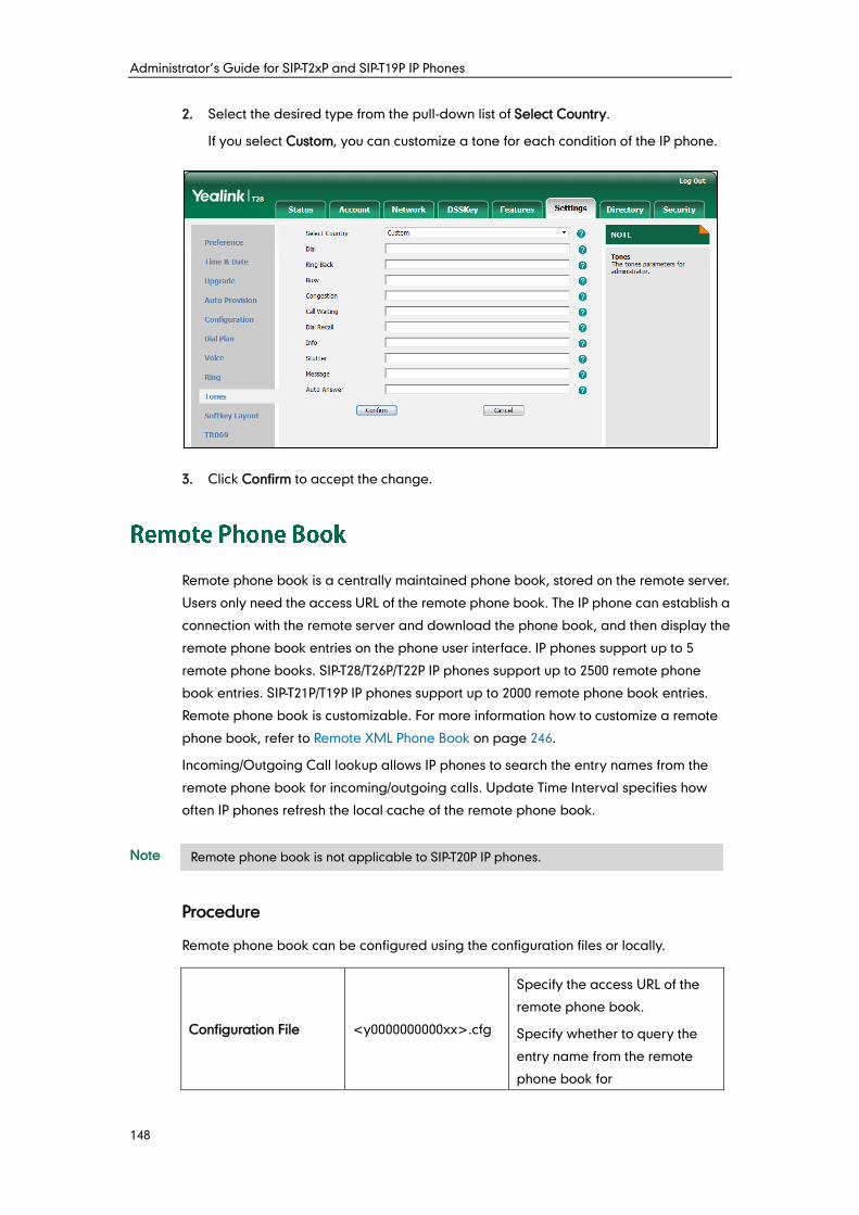
Administrator’s Guide for SIP-T2xP and SIP-T19P IP Phones
148
2. Select the desired type from the pull-down list of Select Country.
If you select Custom, you can customize a tone for each condition of the IP phone.
3. Click Confirm to accept the change.
Remote phone book is a centrally maintained phone book, stored on the remote server.
Users only need the access URL of the remote phone book. The IP phone can establish a
connection with the remote server and download the phone book, and then display the
remote phone book entries on the phone user interface. IP phones support up to 5
remote phone books. SIP-T28/T26P/T22P IP phones support up to 2500 remote phone
book entries. SIP-T21P/T19P IP phones support up to 2000 remote phone book entries.
Remote phone book is customizable. For more information how to customize a remote
phone book, refer to Remote XML Phone Book on page 246.
Incoming/Outgoing Call lookup allows IP phones to search the entry names from the
remote phone book for incoming/outgoing calls. Update Time Interval specifies how
often IP phones refresh the local cache of the remote phone book.
Note
Procedure
Remote phone book can be configured using the configuration files or locally.
Configuration File <y0000000000xx>.cfg
Specify the access URL of the
remote phone book.
Specify whether to query the
entry name from the remote
phone book for
Remote phone book is not applicable to SIP-T20P IP phones.
Configuring Advanced Features
149
outgoing/incoming calls.
Specify how often the IP phone
refreshes the local cache of the
remote phone book.
Specify whether to refresh the
local cache of the remote
phone book at a time when
accessing the remote phone
book.
For more information, refer to
Remote Phone Book on page
352.
Local Web User Interface
Specify the access URL of the
remote phone book.
Navigate to:
http://<phoneIPAddress>/servl
et?p=contacts-remote&q=load
Specify whether to query the
entry name from the remote
phone book for
outgoing/incoming calls.
Specify how often the IP phone
refreshes the local cache of the
remote phone book.
Navigate to:
http://<phoneIPAddress>/servl
et?p=contacts-remote&q=load
To specify access URL of the remote phone book via web user interface:
1. Click on Directory->Remote Phone Book.
2. Enter the access URL in the Remote URL field.
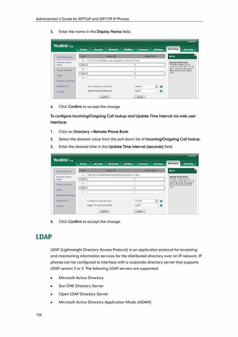
Administrator’s Guide for SIP-T2xP and SIP-T19P IP Phones
150
3. Enter the name in the Display Name field.
4. Click Confirm to accept the change
To configure Incoming/Outgoing Call lookup and Update Time Interval via web user
interface:
1. Click on Directory->Remote Phone Book.
2. Select the desired value from the pull-down list of Incoming/Outgoing Call lookup.
3. Enter the desired time in the Update Time Interval (seconds) field.
4. Click Confirm to accept the change.
LDAP (Lightweight Directory Access Protocol) is an application protocol for accessing
and maintaining information services for the distributed directory over an IP network. IP
phones can be configured to interface with a corporate directory server that supports
LDAP version 2 or 3. The following LDAP servers are supported:
Microsoft Active Directory
Sun ONE Directory Server
Open LDAP Directory Server
Microsoft Active Directory Application Mode (ADAM)
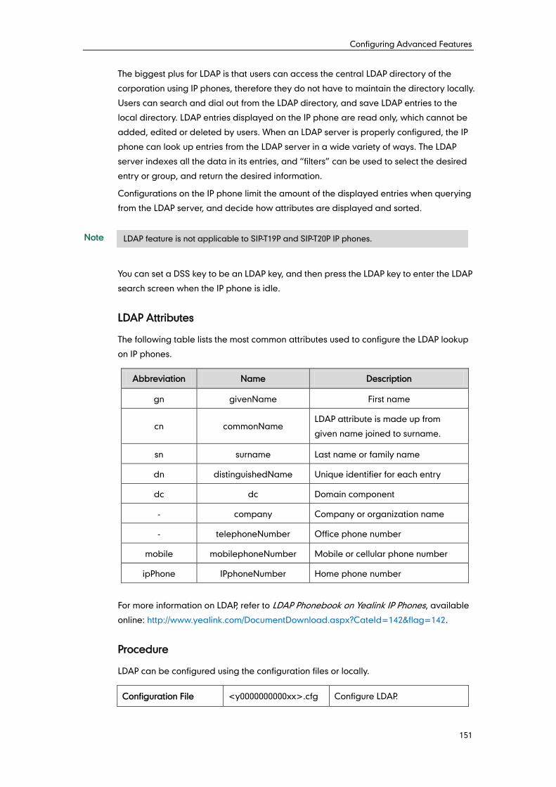
Configuring Advanced Features
151
The biggest plus for LDAP is that users can access the central LDAP directory of the
corporation using IP phones, therefore they do not have to maintain the directory locally.
Users can search and dial out from the LDAP directory, and save LDAP entries to the
local directory. LDAP entries displayed on the IP phone are read only, which cannot be
added, edited or deleted by users. When an LDAP server is properly configured, the IP
phone can look up entries from the LDAP server in a wide variety of ways. The LDAP
server indexes all the data in its entries, and “filters” can be used to select the desired
entry or group, and return the desired information.
Configurations on the IP phone limit the amount of the displayed entries when querying
from the LDAP server, and decide how attributes are displayed and sorted.
Note
You can set a DSS key to be an LDAP key, and then press the LDAP key to enter the LDAP
search screen when the IP phone is idle.
LDAP Attributes
The following table lists the most common attributes used to configure the LDAP lookup
on IP phones.
Abbreviation Name Description
gn givenName First name
cn commonName LDAP attribute is made up from
given name joined to surname.
sn surname Last name or family name
dn distinguishedName Unique identifier for each entry
dc dc Domain component
- company Company or organization name
- telephoneNumber Office phone number
mobile mobilephoneNumber Mobile or cellular phone number
ipPhone IPphoneNumber Home phone number
For more information on LDAP, refer to LDAP Phonebook on Yealink IP Phones, available
online: http://www.yealink.com/DocumentDownload.aspx?CateId=142&flag=142.
Procedure
LDAP can be configured using the configuration files or locally.
Configuration File <y0000000000xx>.cfg Configure LDAP.
LDAP feature is not applicable to SIP-T19P and SIP-T20P IP phones.
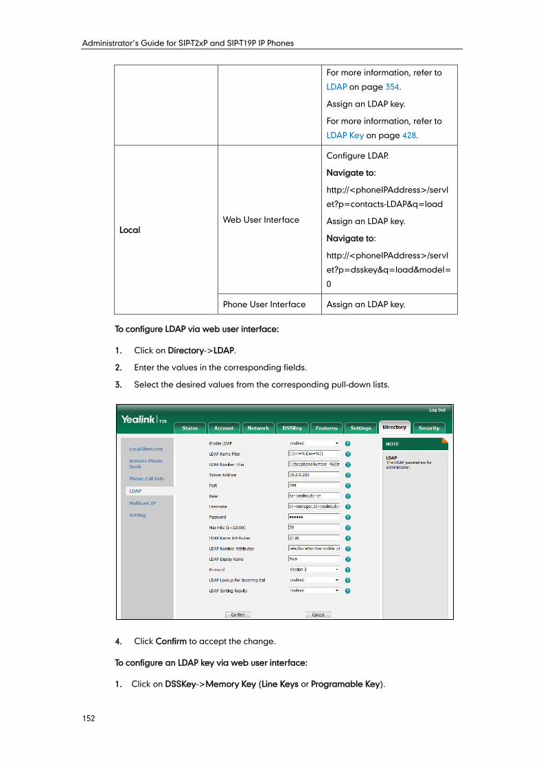
Administrator’s Guide for SIP-T2xP and SIP-T19P IP Phones
152
For more information, refer to
LDAP on page 354.
Assign an LDAP key.
For more information, refer to
LDAP Key on page 428.
Local Web User Interface
Configure LDAP.
Navigate to:
http://<phoneIPAddress>/servl
et?p=contacts-LDAP&q=load
Assign an LDAP key.
Navigate to:
http://<phoneIPAddress>/servl
et?p=dsskey&q=load&model=
0
Phone User Interface Assign an LDAP key.
To configure LDAP via web user interface:
1. Click on Directory->LDAP.
2. Enter the values in the corresponding fields.
3. Select the desired values from the corresponding pull-down lists.
4. Click Confirm to accept the change.
To configure an LDAP key via web user interface:
1. Click on DSSKey->Memory Key (Line Keys or Programable Key).
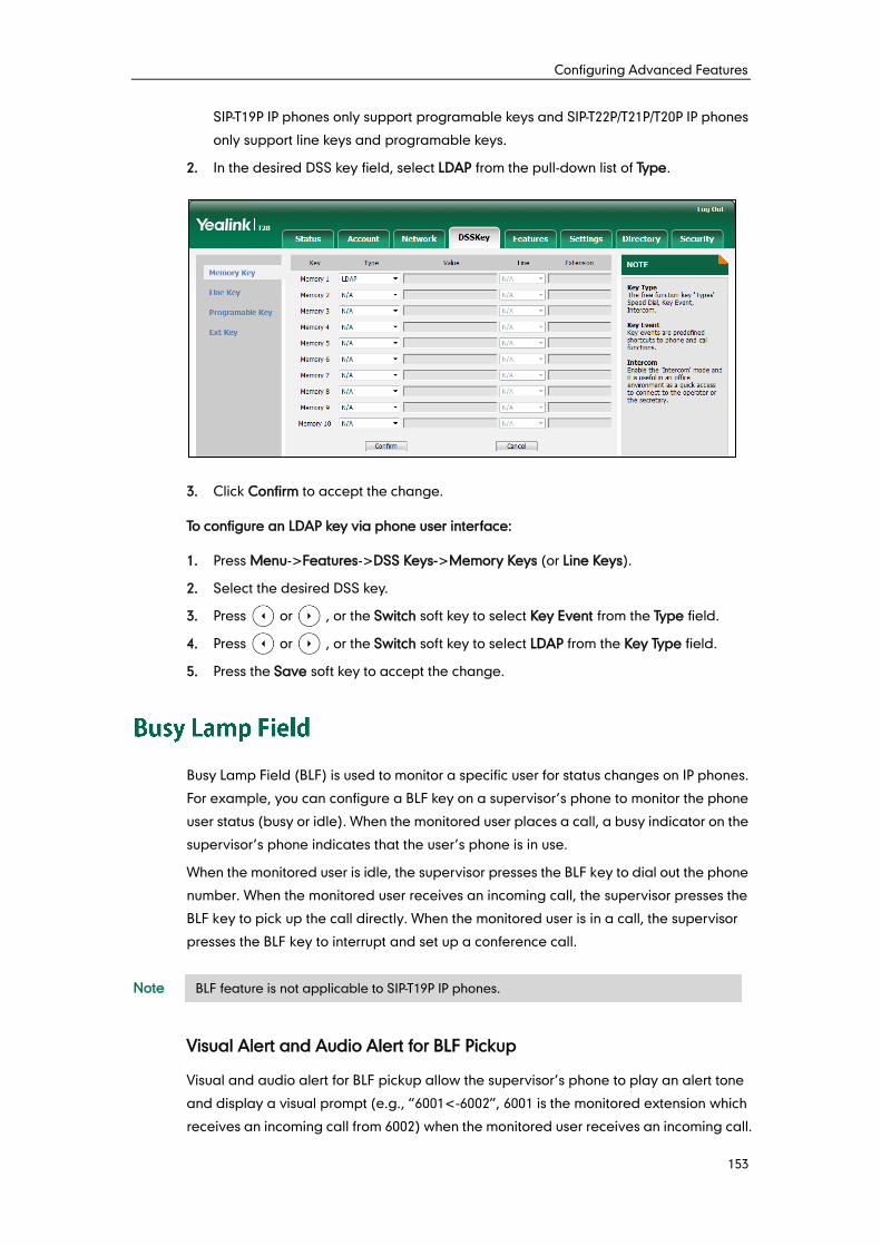
Configuring Advanced Features
153
SIP-T19P IP phones only support programable keys and SIP-T22P/T21P/T20P IP phones
only support line keys and programable keys.
2. In the desired DSS key field, select LDAP from the pull-down list of Type.
3. Click Confirm to accept the change.
To configure an LDAP key via phone user interface:
1. Press Menu->Features->DSS Keys->Memory Keys (or Line Keys).
2. Select the desired DSS key.
3. Press or , or the Switch soft key to select Key Event from the Type field.
4. Press or , or the Switch soft key to select LDAP from the Key Type field.
5. Press the Save soft key to accept the change.
Busy Lamp Field (BLF) is used to monitor a specific user for status changes on IP phones.
For example, you can configure a BLF key on a supervisor’s phone to monitor the phone
user status (busy or idle). When the monitored user places a call, a busy indicator on the
supervisor’s phone indicates that the user’s phone is in use.
When the monitored user is idle, the supervisor presses the BLF key to dial out the phone
number. When the monitored user receives an incoming call, the supervisor presses the
BLF key to pick up the call directly. When the monitored user is in a call, the supervisor
presses the BLF key to interrupt and set up a conference call.
Note
Visual Alert and Audio Alert for BLF Pickup
Visual and audio alert for BLF pickup allow the supervisor’s phone to play an alert tone
and display a visual prompt (e.g., “6001<-6002”, 6001 is the monitored extension which
receives an incoming call from 6002) when the monitored user receives an incoming call.
BLF feature is not applicable to SIP-T19P IP phones.
Administrator’s Guide for SIP-T2xP and SIP-T19P IP Phones
154
In addition to the BLF key, visual alert for BLF pickup feature enables the supervisor to
pick up the monitored user’s incoming call by pressing the Pickup soft key. The directed
call pickup code must be configured in advance. For more information on how to
configure the directed call pickup code for the Pickup soft key, refer to Directed Call
Pickup on page 119.
Note
BLF LED Mode
BLF LED Mode provides four kinds of definition for the BLF key LED status. The following
table lists the LED statuses of the BLF key when BLF LED Mode is set to 0, 1, 2 or 3
respectively. The default value of BLF LED mode is 0.
Line key LED (configured as a BLF key and BLF LED Mode is set to 0)
LED Status Description
Solid green The monitored user is idle.
Fast flashing green (200ms) The monitored user receives an incoming call.
Slow flashing green (500ms)
The monitored user is dialing.
The monitored user is talking.
The monitored user’s conversation is placed on
hold.
Slow flashing green (1s) The call is parked against the monitored user’s
phone number.
Off The monitored user does not exist.
Memory key LED (configured as a BLF key and BLF LED Mode is set to 0)
LED Status Description
Solid green The monitored user is idle.
Fast flashing red (200ms) The monitored user receives an incoming call.
Solid red The monitored user is dialing.
The monitored user is talking.
Slow flashing red (1s)
The call is parked against the monitored user’s
phone number.
The monitored user’s conversation is placed on
hold.
Off The monitored user does not exist.
Visual alert for BLF pickup feature is not applicable to SIP-T20P IP phones.
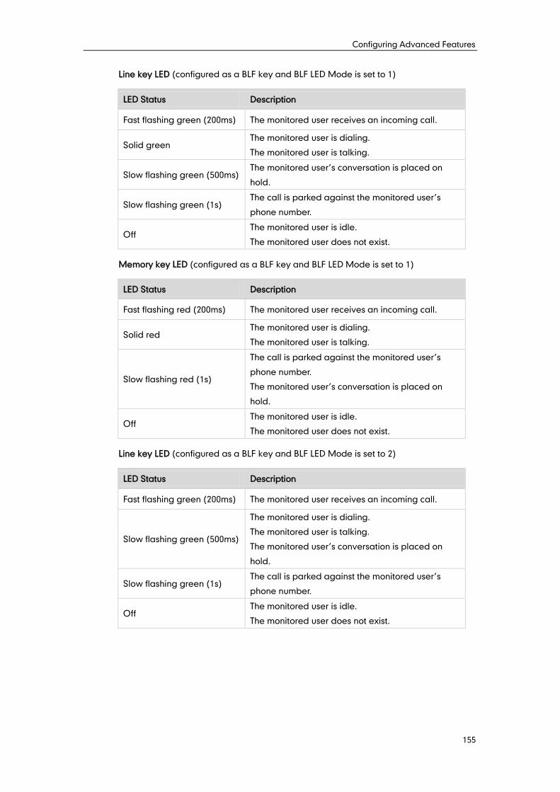
Configuring Advanced Features
155
Line key LED (configured as a BLF key and BLF LED Mode is set to 1)
LED Status Description
Fast flashing green (200ms) The monitored user receives an incoming call.
Solid green The monitored user is dialing.
The monitored user is talking.
Slow flashing green (500ms) The monitored user’s conversation is placed on
hold.
Slow flashing green (1s) The call is parked against the monitored user’s
phone number.
Off The monitored user is idle.
The monitored user does not exist.
Memory key LED (configured as a BLF key and BLF LED Mode is set to 1)
LED Status Description
Fast flashing red (200ms) The monitored user receives an incoming call.
Solid red The monitored user is dialing.
The monitored user is talking.
Slow flashing red (1s)
The call is parked against the monitored user’s
phone number.
The monitored user’s conversation is placed on
hold.
Off The monitored user is idle.
The monitored user does not exist.
Line key LED (configured as a BLF key and BLF LED Mode is set to 2)
LED Status Description
Fast flashing green (200ms) The monitored user receives an incoming call.
Slow flashing green (500ms)
The monitored user is dialing.
The monitored user is talking.
The monitored user’s conversation is placed on
hold.
Slow flashing green (1s) The call is parked against the monitored user’s
phone number.
Off The monitored user is idle.
The monitored user does not exist.
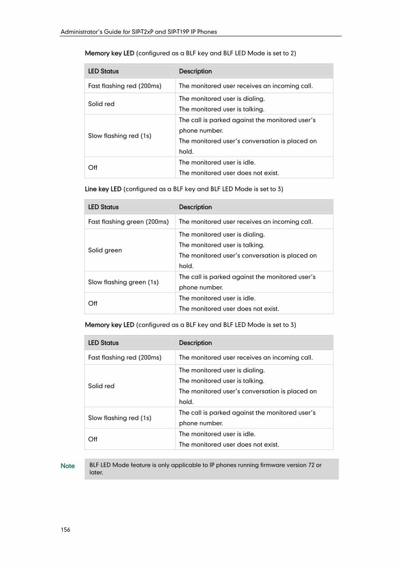
Administrator’s Guide for SIP-T2xP and SIP-T19P IP Phones
156
Memory key LED (configured as a BLF key and BLF LED Mode is set to 2)
LED Status Description
Fast flashing red (200ms) The monitored user receives an incoming call.
Solid red The monitored user is dialing.
The monitored user is talking.
Slow flashing red (1s)
The call is parked against the monitored user’s
phone number.
The monitored user’s conversation is placed on
hold.
Off The monitored user is idle.
The monitored user does not exist.
Line key LED (configured as a BLF key and BLF LED Mode is set to 3)
LED Status Description
Fast flashing green (200ms) The monitored user receives an incoming call.
Solid green
The monitored user is dialing.
The monitored user is talking.
The monitored user’s conversation is placed on
hold.
Slow flashing green (1s) The call is parked against the monitored user’s
phone number.
Off The monitored user is idle.
The monitored user does not exist.
Memory key LED (configured as a BLF key and BLF LED Mode is set to 3)
LED Status Description
Fast flashing red (200ms) The monitored user receives an incoming call.
Solid red
The monitored user is dialing.
The monitored user is talking.
The monitored user’s conversation is placed on
hold.
Slow flashing red (1s) The call is parked against the monitored user’s
phone number.
Off The monitored user is idle.
The monitored user does not exist.
Note
BLF LED Mode feature is only applicable to IP phones running firmware version 72 or
later.
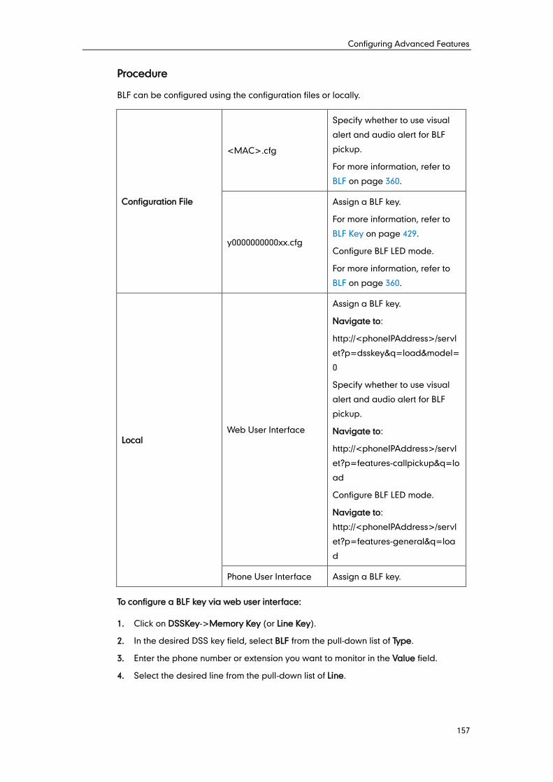
Configuring Advanced Features
157
Procedure
BLF can be configured using the configuration files or locally.
Configuration File
<MAC>.cfg
Specify whether to use visual
alert and audio alert for BLF
pickup.
For more information, refer to
BLF on page 360.
y0000000000xx.cfg
Assign a BLF key.
For more information, refer to
BLF Key on page 429.
Configure BLF LED mode.
For more information, refer to
BLF on page 360.
Local Web User Interface
Assign a BLF key.
Navigate to:
http://<phoneIPAddress>/servl
et?p=dsskey&q=load&model=
0
Specify whether to use visual
alert and audio alert for BLF
pickup.
Navigate to:
http://<phoneIPAddress>/servl
et?p=features-callpickup&q=lo
ad
Configure BLF LED mode.
Navigate to:
http://<phoneIPAddress>/servl
et?p=features-general&q=loa
d
Phone User Interface Assign a BLF key.
To configure a BLF key via web user interface:
1. Click on DSSKey->Memory Key (or Line Key).
2. In the desired DSS key field, select BLF from the pull-down list of Type.
3. Enter the phone number or extension you want to monitor in the Value field.
4. Select the desired line from the pull-down list of Line.
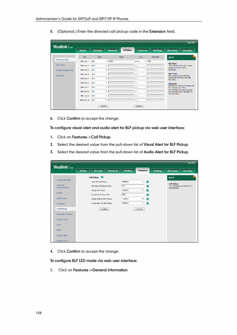
Administrator’s Guide for SIP-T2xP and SIP-T19P IP Phones
158
5. (Optional.) Enter the directed call pickup code in the Extension field.
6. Click Confirm to accept the change.
To configure visual alert and audio alert for BLF pickup via web user interface:
1. Click on Features->Call Pickup.
2. Select the desired value from the pull-down list of Visual Alert for BLF Pickup.
3. Select the desired value from the pull-down list of Audio Alert for BLF Pickup.
4. Click Confirm to accept the change.
To configure BLF LED mode via web user interface:
1. Click on Features->General Information.
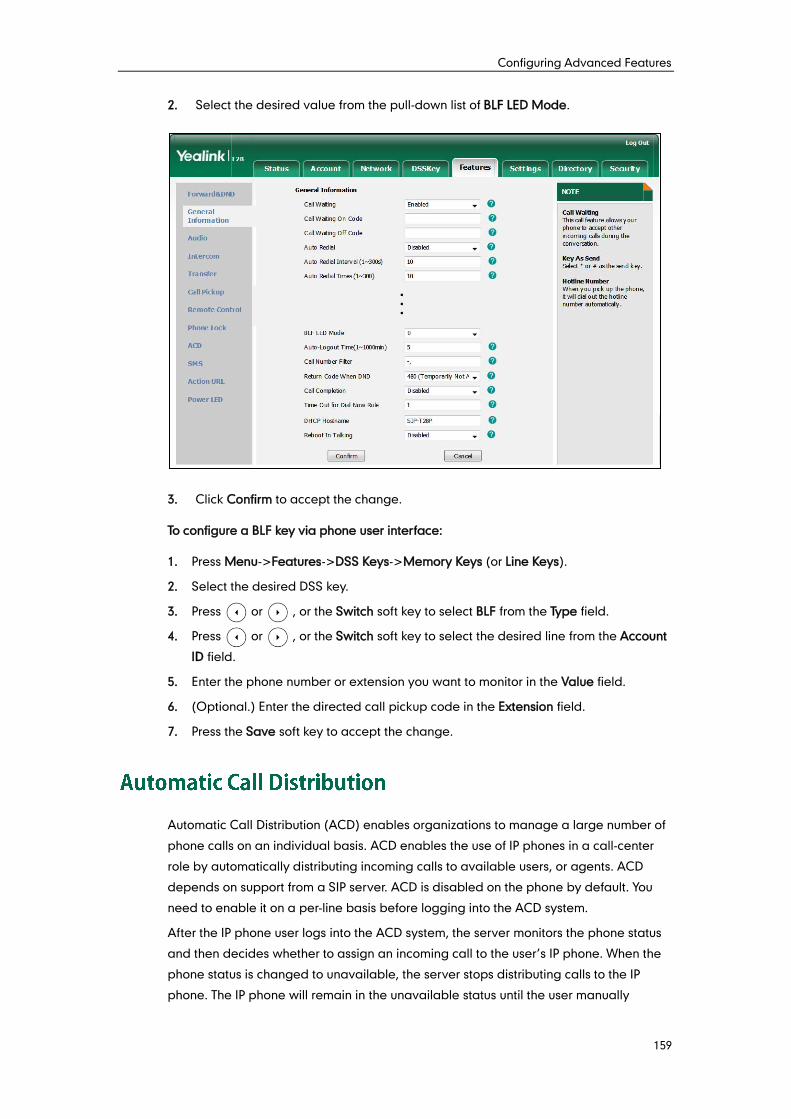
Configuring Advanced Features
159
2. Select the desired value from the pull-down list of BLF LED Mode.
3. Click Confirm to accept the change.
To configure a BLF key via phone user interface:
1. Press Menu->Features->DSS Keys->Memory Keys (or Line Keys).
2. Select the desired DSS key.
3. Press or , or the Switch soft key to select BLF from the Type field.
4. Press or , or the Switch soft key to select the desired line from the Account
ID field.
5. Enter the phone number or extension you want to monitor in the Value field.
6. (Optional.) Enter the directed call pickup code in the Extension field.
7. Press the Save soft key to accept the change.
Automatic Call Distribution (ACD) enables organizations to manage a large number of
phone calls on an individual basis. ACD enables the use of IP phones in a call-center
role by automatically distributing incoming calls to available users, or agents. ACD
depends on support from a SIP server. ACD is disabled on the phone by default. You
need to enable it on a per-line basis before logging into the ACD system.
After the IP phone user logs into the ACD system, the server monitors the phone status
and then decides whether to assign an incoming call to the user’s IP phone. When the
phone status is changed to unavailable, the server stops distributing calls to the IP
phone. The IP phone will remain in the unavailable status until the user manually
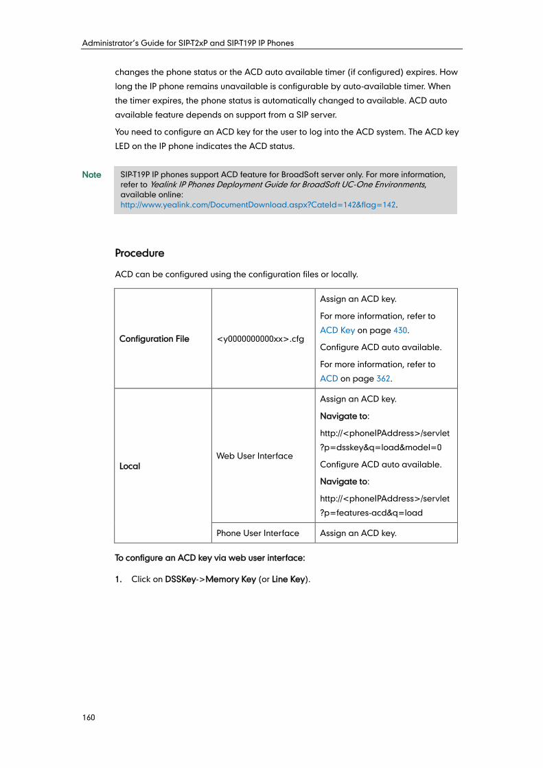
Administrator’s Guide for SIP-T2xP and SIP-T19P IP Phones
160
changes the phone status or the ACD auto available timer (if configured) expires. How
long the IP phone remains unavailable is configurable by auto-available timer. When
the timer expires, the phone status is automatically changed to available. ACD auto
available feature depends on support from a SIP server.
You need to configure an ACD key for the user to log into the ACD system. The ACD key
LED on the IP phone indicates the ACD status.
Note
Procedure
ACD can be configured using the configuration files or locally.
Configuration File <y0000000000xx>.cfg
Assign an ACD key.
For more information, refer to
ACD Key on page 430.
Configure ACD auto available.
For more information, refer to
ACD on page 362.
Local Web User Interface
Assign an ACD key.
Navigate to:
http://<phoneIPAddress>/servlet
?p=dsskey&q=load&model=0
Configure ACD auto available.
Navigate to:
http://<phoneIPAddress>/servlet
?p=features-acd&q=load
Phone User Interface Assign an ACD key.
To configure an ACD key via web user interface:
1. Click on DSSKey->Memory Key (or Line Key).
SIP-T19P IP phones support ACD feature for BroadSoft server only. For more information,
refer to Yealink IP Phones Deployment Guide for BroadSoft UC-One Environments,
available online:
http://www.yealink.com/DocumentDownload.aspx?CateId=142&flag=142.
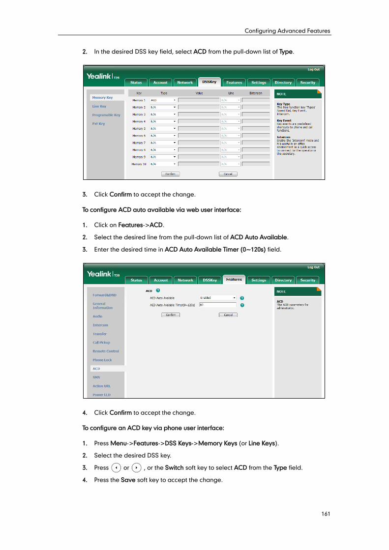
Configuring Advanced Features
161
2. In the desired DSS key field, select ACD from the pull-down list of Type.
3. Click Confirm to accept the change.
To configure ACD auto available via web user interface:
1. Click on Features->ACD.
2. Select the desired line from the pull-down list of ACD Auto Available.
3. Enter the desired time in ACD Auto Available Timer (0~120s) field.
4. Click Confirm to accept the change.
To configure an ACD key via phone user interface:
1. Press Menu->Features->DSS Keys->Memory Keys (or Line Keys).
2. Select the desired DSS key.
3. Press or , or the Switch soft key to select ACD from the Type field.
4. Press the Save soft key to accept the change.
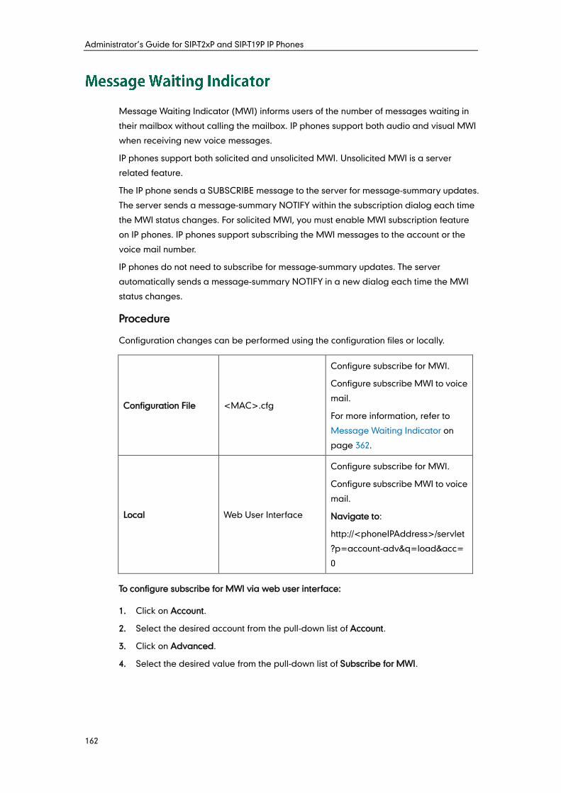
Administrator’s Guide for SIP-T2xP and SIP-T19P IP Phones
162
Message Waiting Indicator (MWI) informs users of the number of messages waiting in
their mailbox without calling the mailbox. IP phones support both audio and visual MWI
when receiving new voice messages.
IP phones support both solicited and unsolicited MWI. Unsolicited MWI is a server
related feature.
The IP phone sends a SUBSCRIBE message to the server for message-summary updates.
The server sends a message-summary NOTIFY within the subscription dialog each time
the MWI status changes. For solicited MWI, you must enable MWI subscription feature
on IP phones. IP phones support subscribing the MWI messages to the account or the
voice mail number.
IP phones do not need to subscribe for message-summary updates. The server
automatically sends a message-summary NOTIFY in a new dialog each time the MWI
status changes.
Procedure
Configuration changes can be performed using the configuration files or locally.
Configuration File <MAC>.cfg
Configure subscribe for MWI.
Configure subscribe MWI to voice
mail.
For more information, refer to
Message Waiting Indicator on
page 362.
Local Web User Interface
Configure subscribe for MWI.
Configure subscribe MWI to voice
mail.
Navigate to:
http://<phoneIPAddress>/servlet
?p=account-adv&q=load&acc=
0
To configure subscribe for MWI via web user interface:
1. Click on Account.
2. Select the desired account from the pull-down list of Account.
3. Click on Advanced.
4. Select the desired value from the pull-down list of Subscribe for MWI.
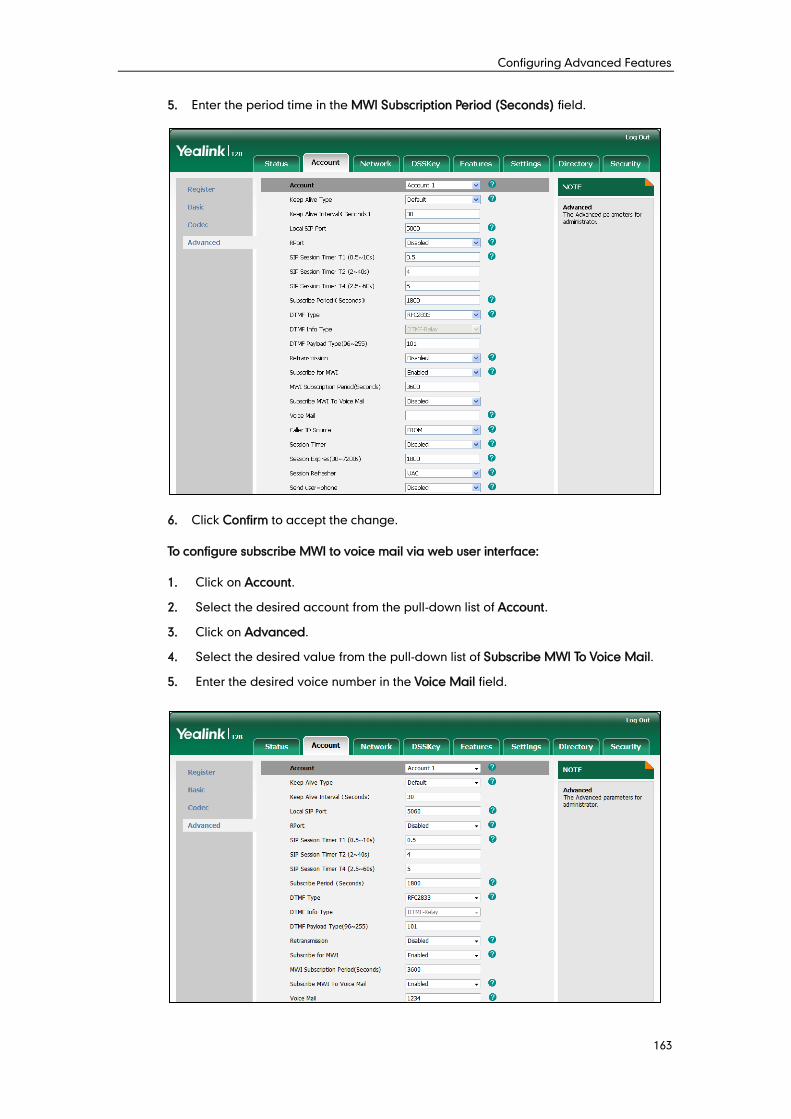
Configuring Advanced Features
163
5. Enter the period time in the MWI Subscription Period (Seconds) field.
6. Click Confirm to accept the change.
To configure subscribe MWI to voice mail via web user interface:
1. Click on Account.
2. Select the desired account from the pull-down list of Account.
3. Click on Advanced.
4. Select the desired value from the pull-down list of Subscribe MWI To Voice Mail.
5. Enter the desired voice number in the Voice Mail field.
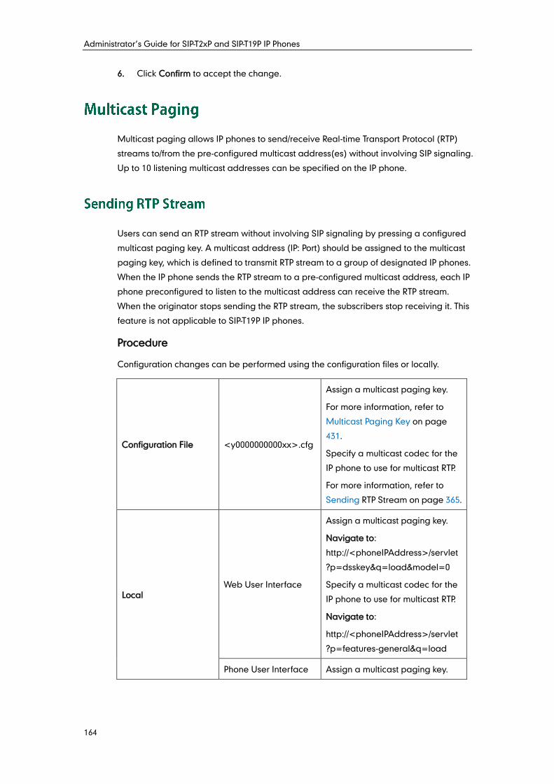
Administrator’s Guide for SIP-T2xP and SIP-T19P IP Phones
164
6. Click Confirm to accept the change.
Multicast paging allows IP phones to send/receive Real-time Transport Protocol (RTP)
streams to/from the pre-configured multicast address(es) without involving SIP signaling.
Up to 10 listening multicast addresses can be specified on the IP phone.
Users can send an RTP stream without involving SIP signaling by pressing a configured
multicast paging key. A multicast address (IP: Port) should be assigned to the multicast
paging key, which is defined to transmit RTP stream to a group of designated IP phones.
When the IP phone sends the RTP stream to a pre-configured multicast address, each IP
phone preconfigured to listen to the multicast address can receive the RTP stream.
When the originator stops sending the RTP stream, the subscribers stop receiving it. This
feature is not applicable to SIP-T19P IP phones.
Procedure
Configuration changes can be performed using the configuration files or locally.
Configuration File <y0000000000xx>.cfg
Assign a multicast paging key.
For more information, refer to
Multicast Paging Key on page
431.
Specify a multicast codec for the
IP phone to use for multicast RTP.
For more information, refer to
Sending RTP Stream on page 365.
Local Web User Interface
Assign a multicast paging key.
Navigate to:
http://<phoneIPAddress>/servlet
?p=dsskey&q=load&model=0
Specify a multicast codec for the
IP phone to use for multicast RTP.
Navigate to:
http://<phoneIPAddress>/servlet
?p=features-general&q=load
Phone User Interface Assign a multicast paging key.
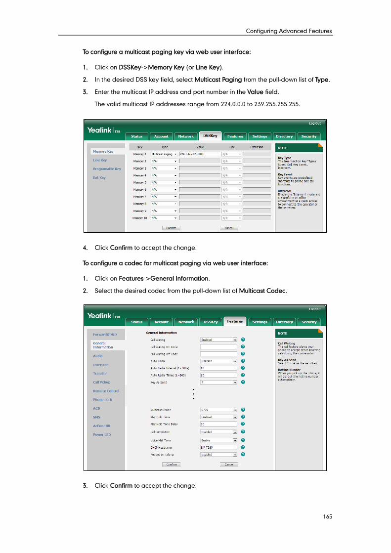
Configuring Advanced Features
165
To configure a multicast paging key via web user interface:
1. Click on DSSKey->Memory Key (or Line Key).
2. In the desired DSS key field, select Multicast Paging from the pull-down list of Type.
3. Enter the multicast IP address and port number in the Value field.
The valid multicast IP addresses range from 224.0.0.0 to 239.255.255.255.
4. Click Confirm to accept the change.
To configure a codec for multicast paging via web user interface:
1. Click on Features->General Information.
2. Select the desired codec from the pull-down list of Multicast Codec.
3. Click Confirm to accept the change.
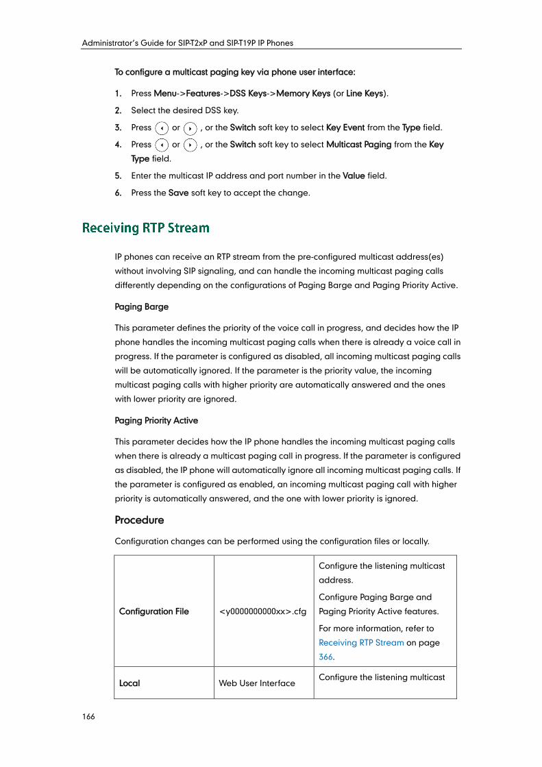
Administrator’s Guide for SIP-T2xP and SIP-T19P IP Phones
166
To configure a multicast paging key via phone user interface:
1. Press Menu->Features->DSS Keys->Memory Keys (or Line Keys).
2. Select the desired DSS key.
3. Press or , or the Switch soft key to select Key Event from the Type field.
4. Press or , or the Switch soft key to select Multicast Paging from the Key
Type field.
5. Enter the multicast IP address and port number in the Value field.
6. Press the Save soft key to accept the change.
IP phones can receive an RTP stream from the pre-configured multicast address(es)
without involving SIP signaling, and can handle the incoming multicast paging calls
differently depending on the configurations of Paging Barge and Paging Priority Active.
Paging Barge
This parameter defines the priority of the voice call in progress, and decides how the IP
phone handles the incoming multicast paging calls when there is already a voice call in
progress. If the parameter is configured as disabled, all incoming multicast paging calls
will be automatically ignored. If the parameter is the priority value, the incoming
multicast paging calls with higher priority are automatically answered and the ones
with lower priority are ignored.
Paging Priority Active
This parameter decides how the IP phone handles the incoming multicast paging calls
when there is already a multicast paging call in progress. If the parameter is configured
as disabled, the IP phone will automatically ignore all incoming multicast paging calls. If
the parameter is configured as enabled, an incoming multicast paging call with higher
priority is automatically answered, and the one with lower priority is ignored.
Procedure
Configuration changes can be performed using the configuration files or locally.
Configuration File <y0000000000xx>.cfg
Configure the listening multicast
address.
Configure Paging Barge and
Paging Priority Active features.
For more information, refer to
Receiving RTP Stream on page
366.
Local Web User Interface Configure the listening multicast
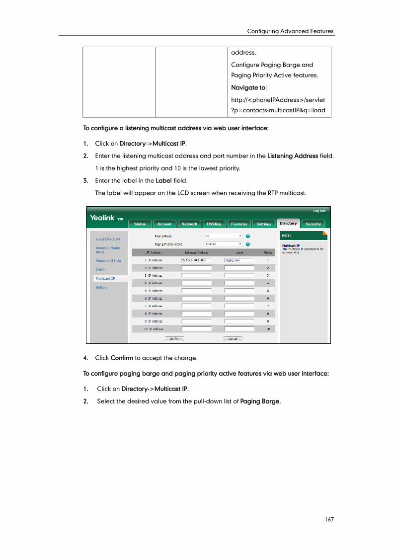
Configuring Advanced Features
167
address.
Configure Paging Barge and
Paging Priority Active features.
Navigate to:
http://<phoneIPAddress>/servlet
?p=contacts-multicastIP&q=load
To configure a listening multicast address via web user interface:
1. Click on Directory->Multicast IP.
2. Enter the listening multicast address and port number in the Listening Address field.
1 is the highest priority and 10 is the lowest priority.
3. Enter the label in the Label field.
The label will appear on the LCD screen when receiving the RTP multicast.
4. Click Confirm to accept the change.
To configure paging barge and paging priority active features via web user interface:
1. Click on Directory->Multicast IP.
2. Select the desired value from the pull-down list of Paging Barge.
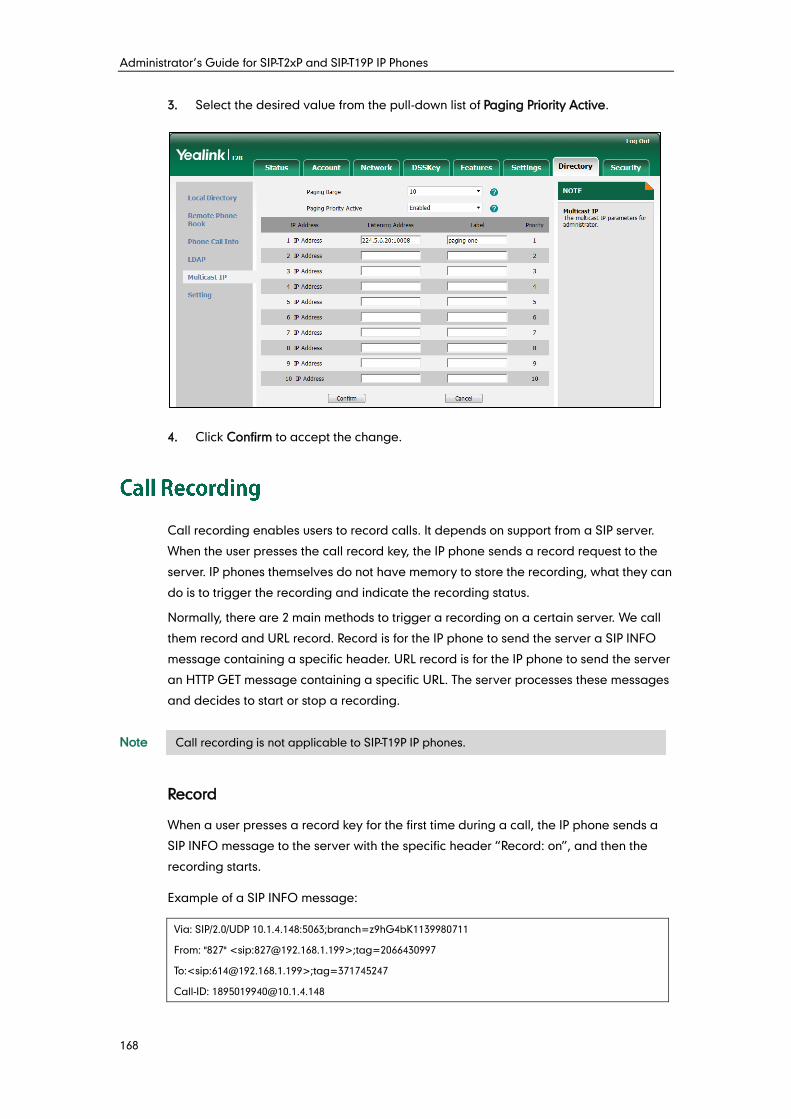
Administrator’s Guide for SIP-T2xP and SIP-T19P IP Phones
168
3. Select the desired value from the pull-down list of Paging Priority Active.
4. Click Confirm to accept the change.
Call recording enables users to record calls. It depends on support from a SIP server.
When the user presses the call record key, the IP phone sends a record request to the
server. IP phones themselves do not have memory to store the recording, what they can
do is to trigger the recording and indicate the recording status.
Normally, there are 2 main methods to trigger a recording on a certain server. We call
them record and URL record. Record is for the IP phone to send the server a SIP INFO
message containing a specific header. URL record is for the IP phone to send the server
an HTTP GET message containing a specific URL. The server processes these messages
and decides to start or stop a recording.
Note
Record
When a user presses a record key for the first time during a call, the IP phone sends a
SIP INFO message to the server with the specific header “Record: on”, and then the
recording starts.
Example of a SIP INFO message:
Via: SIP/2.0/UDP 10.1.4.148:5063;branch=z9hG4bK1139980711
From: "827" <sip:[email protected]>;tag=2066430997
To:<sip:[email protected]>;tag=371745247
Call-ID: [email protected]
Call recording is not applicable to SIP-T19P IP phones.
Configuring Advanced Features
169
CSeq: 2 INFO
Contact: <sip:[email protected]:5063>
Max-Forwards: 70
User-Agent: Yealink SIP-T28P 2.72.0.1
Record: on
Content-Length: 0
When the user presses the record key for the second time, the IP phone sends a SIP
INFO message to the server with the specific header “Record: off”, and then the
recording stops.
Example of a SIP INFO message:
Via: SIP/2.0/UDP 10.1.4.148:5063;branch=z9hG4bK1619489730
From: "827" <sip:[email protected]>;tag=1831694891
To:<sip:[email protected]>;tag=2228378244
Call-ID: [email protected]
CSeq: 3 INFO
Contact: <sip:[email protected]:5063>
Max-Forwards: 70
User-Agent: Yealink SIP-T28P 2.72.0.1
Record: off
Content-Length: 0
URL Record
When a user presses a URL record key for the first time during a call, the IP phone sends
an HTTP GET message to the server.
Example of an HTTP GET message:
Get /phonerecording.cgi?model=yealink HTTP/1.0\r\n
Request Method: GET
Request URI: /phonerecording.cgi?model=yealink
Request version: HTTP/1.0
Host: 10.1.2.224\r\n
User-agent: yealink SIP-T28P 2.72.0.1 00:16:65:11:30:68\r\n
If the recording is successfully started, the server will respond with a 200 OK message.
Example of a 200 OK message:
<YealinkIPPhoneText>
<Title>
</Title>
<Text>
The recording session is successfully started.
</Text>
Administrator’s Guide for SIP-T2xP and SIP-T19P IP Phones
170
<YealinkIPPhoneText>
If the recording fails for some reasons, for example, the recording box is full, the server
will respond with a 200 OK message.
Example of a 200 OK message:
<YealinkIPPhoneText>
<Title>
</Title>
<Text>
Probably the recording box is full.
</Text>
<YealinkIPPhoneText>
When the user presses the URL record key for the second time, the IP phone sends an
HTTP GET message to the server, and then the server will respond with a 200 OK
message.
Example of a 200 OK message:
<YealinkIPPhoneText>
<Title>
</Title>
<Text>
The recording session is successfully stopped.
</Text>
<YealinkIPPhoneText>
Procedure
Call recording key can be configured using the configuration files or locally.
Configuration File <y0000000000xx>.cfg
Assign a record key.
For more information, refer to
Record Key on page 432.
Assign a URL record key.
For more information, refer to URL
Record Key on page 432.
Local
Web User Interface
Assign a record key and URL
record key.
Navigate to:
http://<phoneIPAddress>/servlet
?p=dsskey&q=load&model=0
Phone User Interface Assign a record key and URL
record key.
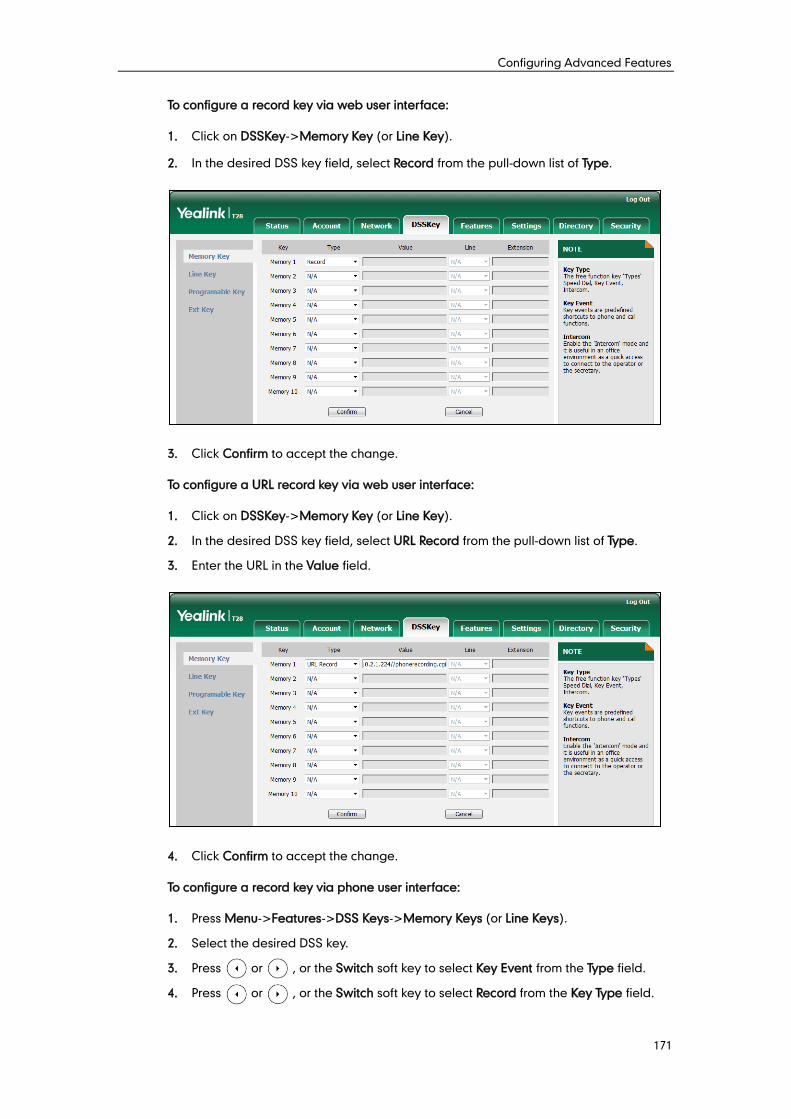
Configuring Advanced Features
171
To configure a record key via web user interface:
1. Click on DSSKey->Memory Key (or Line Key).
2. In the desired DSS key field, select Record from the pull-down list of Type.
3. Click Confirm to accept the change.
To configure a URL record key via web user interface:
1. Click on DSSKey->Memory Key (or Line Key).
2. In the desired DSS key field, select URL Record from the pull-down list of Type.
3. Enter the URL in the Value field.
4. Click Confirm to accept the change.
To configure a record key via phone user interface:
1. Press Menu->Features->DSS Keys->Memory Keys (or Line Keys).
2. Select the desired DSS key.
3. Press or , or the Switch soft key to select Key Event from the Type field.
4. Press or , or the Switch soft key to select Record from the Key Type field.
Administrator’s Guide for SIP-T2xP and SIP-T19P IP Phones
172
5. Press the Save soft key to accept the change.
To configure a URL record key via phone user interface:
1. Press Menu->Features->DSS Keys->Memory Keys (or Line Keys).
2. Select the desired DSS key.
3. Press or , or the Switch soft key to select URL Record from the Type field.
4. Enter the URL in the Value field.
5. Press the Save soft key to accept the change.
Hot desking originates from the definition of being the temporary physical occupant of
a work station or surface by a particular employee. A primary motivation for hot
desking is cost reduction. Hot desking is regularly used in places where not all
employees are in the office at the same time, or not in the office for a long time, which
means actual personal offices would often be vacant, consuming valuable space and
resources.
Hot desking allows a user to clear registration configurations of all accounts on the IP
phone, and then register his account on line 1. In order to use this feature, you need to
assign a hot desking key.
Procedure
Hot desking key can be configured using the configuration files or locally.
Configuration File <y0000000000xx>.cfg
Assign a hot desking key.
For more information, refer to Hot
Desking Key on page 433.
Local
Web User Interface
Assign a hot desking key.
Navigate to:
http://<phoneIPAddress>/servlet
?p=dsskey&q=load&model=0
Phone User Interface Assign a hot desking key.
To configure a hot desking key via web user interface:
1. Click on DSSKey->Memory Keys (Line Key or Programable Key).
SIP-T19P IP phones only support programable keys and SIP-T22P/T21P/T20P IP phones
only support line keys and programable keys.
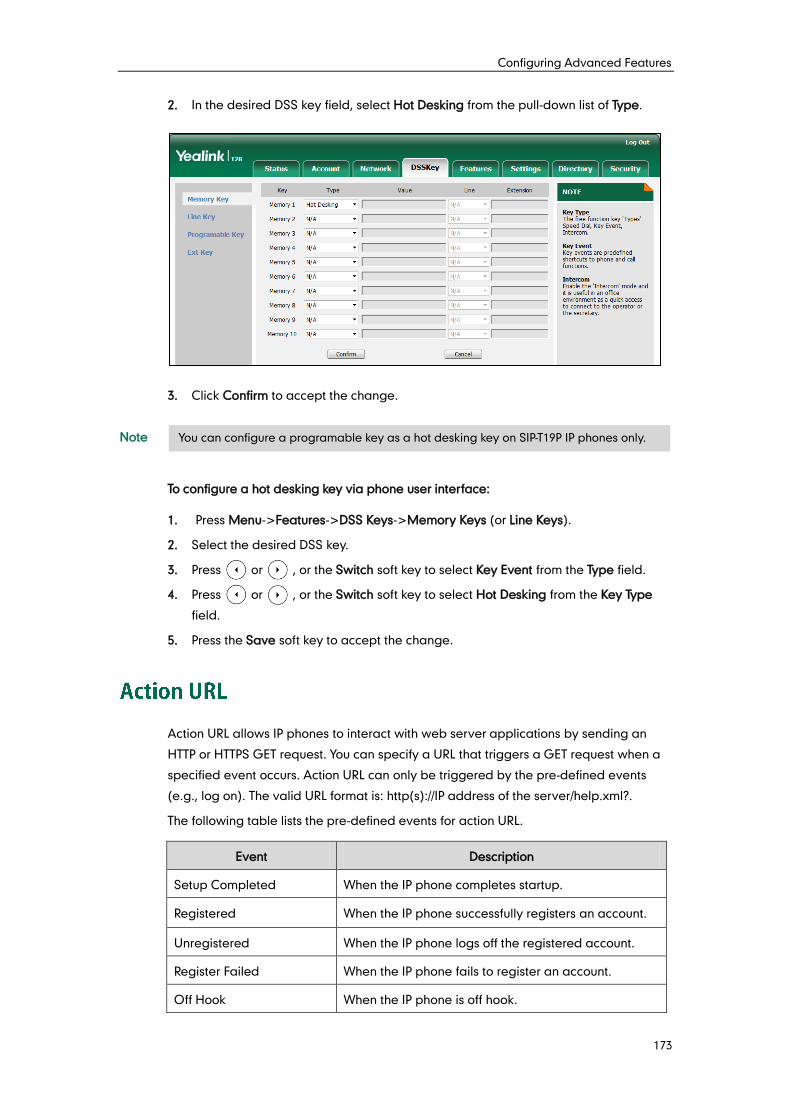
Configuring Advanced Features
173
2. In the desired DSS key field, select Hot Desking from the pull-down list of Type.
3. Click Confirm to accept the change.
Note
To configure a hot desking key via phone user interface:
1. Press Menu->Features->DSS Keys->Memory Keys (or Line Keys).
2. Select the desired DSS key.
3. Press or , or the Switch soft key to select Key Event from the Type field.
4. Press or , or the Switch soft key to select Hot Desking from the Key Type
field.
5. Press the Save soft key to accept the change.
Action URL allows IP phones to interact with web server applications by sending an
HTTP or HTTPS GET request. You can specify a URL that triggers a GET request when a
specified event occurs. Action URL can only be triggered by the pre-defined events
(e.g., log on). The valid URL format is: http(s)://IP address of the server/help.xml?.
The following table lists the pre-defined events for action URL.
Event Description
Setup Completed When the IP phone completes startup.
Registered When the IP phone successfully registers an account.
Unregistered When the IP phone logs off the registered account.
Register Failed When the IP phone fails to register an account.
Off Hook When the IP phone is off hook.
You can configure a programable key as a hot desking key on SIP-T19P IP phones only.
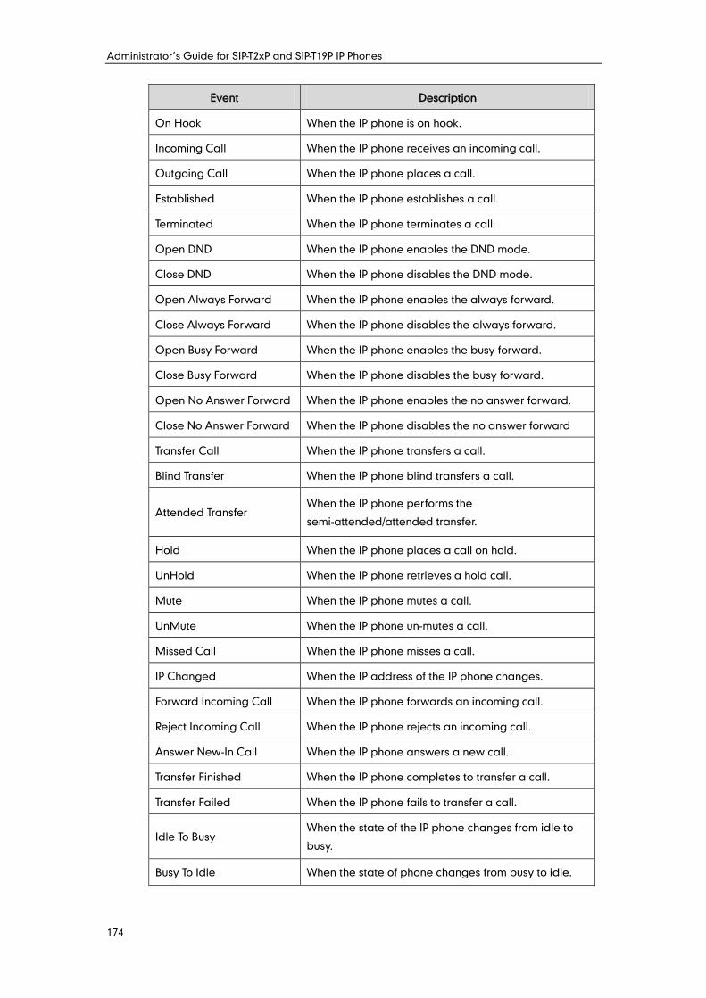
Administrator’s Guide for SIP-T2xP and SIP-T19P IP Phones
174
Event Description
On Hook When the IP phone is on hook.
Incoming Call When the IP phone receives an incoming call.
Outgoing Call When the IP phone places a call.
Established When the IP phone establishes a call.
Terminated When the IP phone terminates a call.
Open DND When the IP phone enables the DND mode.
Close DND When the IP phone disables the DND mode.
Open Always Forward When the IP phone enables the always forward.
Close Always Forward When the IP phone disables the always forward.
Open Busy Forward When the IP phone enables the busy forward.
Close Busy Forward When the IP phone disables the busy forward.
Open No Answer Forward When the IP phone enables the no answer forward.
Close No Answer Forward When the IP phone disables the no answer forward
Transfer Call When the IP phone transfers a call.
Blind Transfer When the IP phone blind transfers a call.
Attended Transfer When the IP phone performs the
semi-attended/attended transfer.
Hold When the IP phone places a call on hold.
UnHold When the IP phone retrieves a hold call.
Mute When the IP phone mutes a call.
UnMute When the IP phone un-mutes a call.
Missed Call When the IP phone misses a call.
IP Changed When the IP address of the IP phone changes.
Forward Incoming Call When the IP phone forwards an incoming call.
Reject Incoming Call When the IP phone rejects an incoming call.
Answer New-In Call When the IP phone answers a new call.
Transfer Finished When the IP phone completes to transfer a call.
Transfer Failed When the IP phone fails to transfer a call.
Idle To Busy When the state of the IP phone changes from idle to
busy.
Busy To Idle When the state of phone changes from busy to idle.
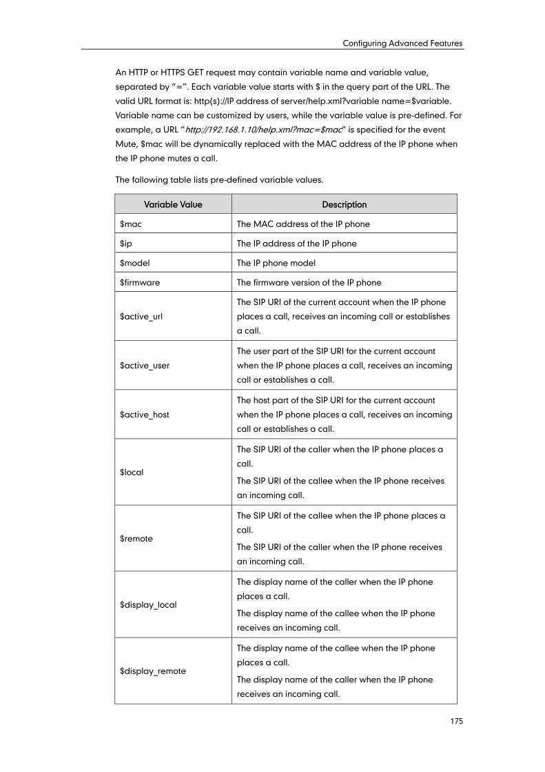
Configuring Advanced Features
175
An HTTP or HTTPS GET request may contain variable name and variable value,
separated by “=”. Each variable value starts with $ in the query part of the URL. The
valid URL format is: http(s)://IP address of server/help.xml?variable name=$variable.
Variable name can be customized by users, while the variable value is pre-defined. For
example, a URL “http://192.168.1.10/help.xml?mac=$mac” is specified for the event
Mute, $mac will be dynamically replaced with the MAC address of the IP phone when
the IP phone mutes a call.
The following table lists pre-defined variable values.
Variable Value Description
$mac The MAC address of the IP phone
$ip The IP address of the IP phone
$model The IP phone model
$firmware The firmware version of the IP phone
$active_url
The SIP URI of the current account when the IP phone
places a call, receives an incoming call or establishes
a call.
$active_user
The user part of the SIP URI for the current account
when the IP phone places a call, receives an incoming
call or establishes a call.
$active_host
The host part of the SIP URI for the current account
when the IP phone places a call, receives an incoming
call or establishes a call.
$local
The SIP URI of the caller when the IP phone places a
call.
The SIP URI of the callee when the IP phone receives
an incoming call.
$remote
The SIP URI of the callee when the IP phone places a
call.
The SIP URI of the caller when the IP phone receives
an incoming call.
$display_local
The display name of the caller when the IP phone
places a call.
The display name of the callee when the IP phone
receives an incoming call.
$display_remote
The display name of the callee when the IP phone
places a call.
The display name of the caller when the IP phone
receives an incoming call.
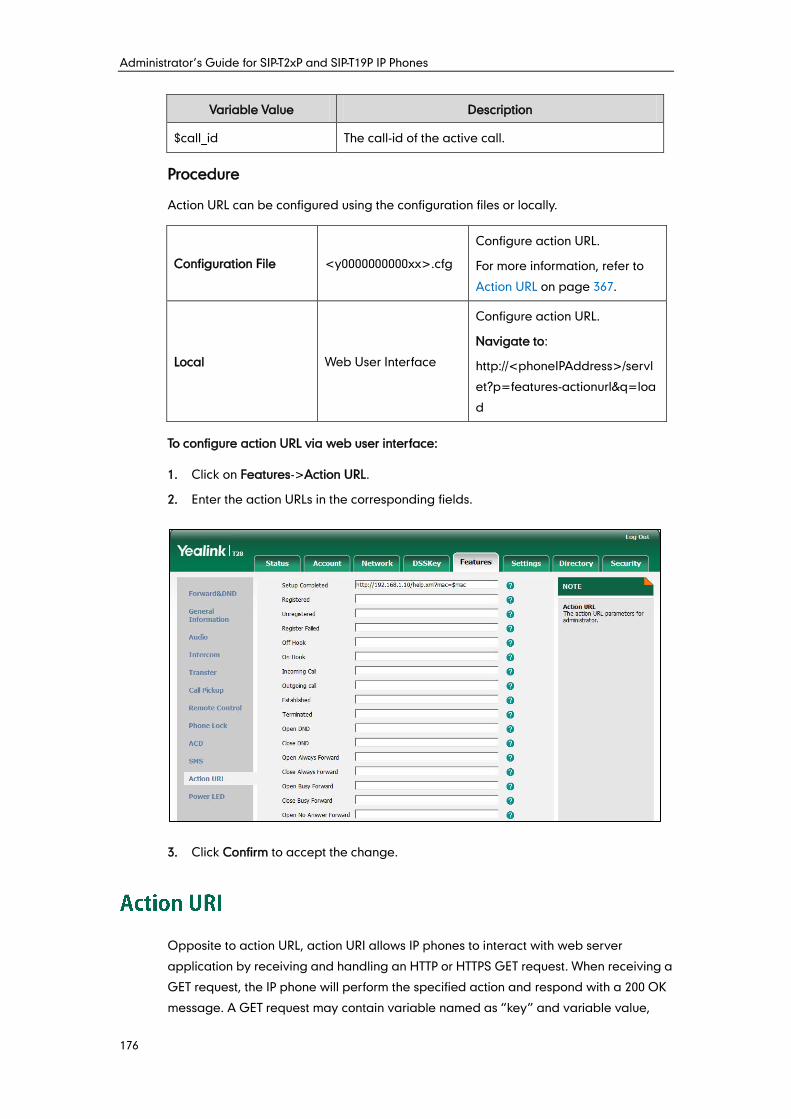
Administrator’s Guide for SIP-T2xP and SIP-T19P IP Phones
176
Variable Value Description
$call_id The call-id of the active call.
Procedure
Action URL can be configured using the configuration files or locally.
Configuration File <y0000000000xx>.cfg
Configure action URL.
For more information, refer to
Action URL on page 367.
Local Web User Interface
Configure action URL.
Navigate to:
http://<phoneIPAddress>/servl
et?p=features-actionurl&q=loa
d
To configure action URL via web user interface:
1. Click on Features->Action URL.
2. Enter the action URLs in the corresponding fields.
3. Click Confirm to accept the change.
Opposite to action URL, action URI allows IP phones to interact with web server
application by receiving and handling an HTTP or HTTPS GET request. When receiving a
GET request, the IP phone will perform the specified action and respond with a 200 OK
message. A GET request may contain variable named as “key” and variable value,
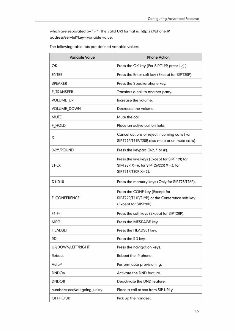
Configuring Advanced Features
177
which are separated by “=”. The valid URI format is: http(s)://phone IP
address/servlet?key=variable value.
The following table lists pre-defined variable values:
Variable Value Phone Action
OK Press the OK key (For SIP-T19P, press ).
ENTER Press the Enter soft key (Except for SIP-T20P).
SPEAKER Press the Speakerphone key.
F_TRANSFER Transfers a call to another party.
VOLUME_UP Increase the volume.
VOLUME_DOWN Decrease the volume.
MUTE Mute the call.
F_HOLD Place an active call on hold.
X Cancel actions or reject incoming calls (For
SIP-T22P/T21P/T20P, also mute or un-mute calls).
0-9/*/POUND Press the keypad (0-9, * or #).
L1-LX
Press the line keys (Except for SIP-T19P, for
SIP-T28P, X=6, for SIP-T26/22P, X=3, for
SIP-T21P/T20P, X=2).
D1-D10 Press the memory keys (Only for SIP-T28/T26P).
F_CONFERENCE
Press the CONF key (Except for
SIP-T22P/T21P/T19P) or the Conference soft key
(Except for SIP-T20P).
F1-F4 Press the soft keys (Except for SIP-T20P).
MSG Press the MESSAGE key.
HEADSET Press the HEADSET key.
RD Press the RD key.
UP/DOWN/LEFT/RIGHT Press the navigation keys.
Reboot Reboot the IP phone.
AutoP Perform auto provisioning.
DNDOn Activate the DND feature.
DNDOff Deactivate the DND feature.
number=xxx&outgoing_uri=y Place a call to xxx from SIP URI y.
OFFHOOK Pick up the handset.
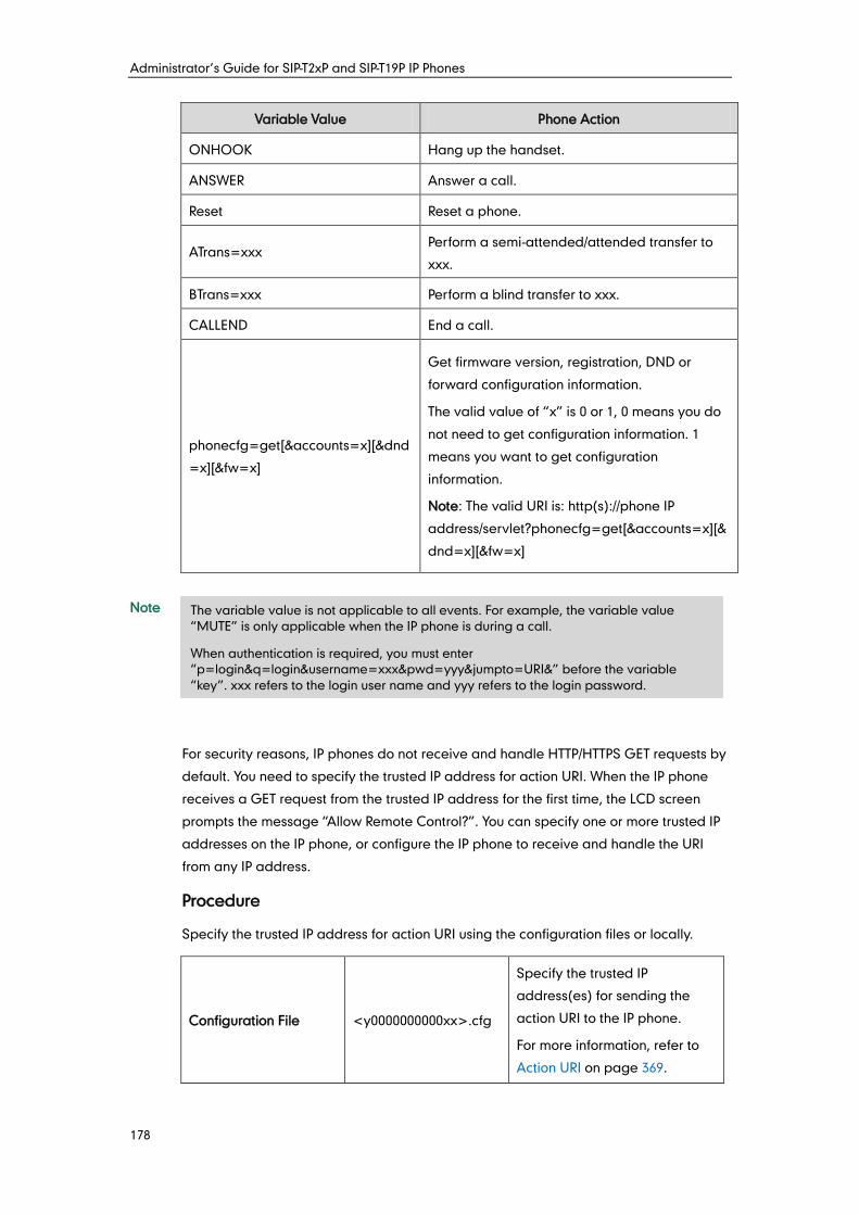
Administrator’s Guide for SIP-T2xP and SIP-T19P IP Phones
178
Variable Value Phone Action
ONHOOK Hang up the handset.
ANSWER Answer a call.
Reset Reset a phone.
ATrans=xxx Perform a semi-attended/attended transfer to
xxx.
BTrans=xxx Perform a blind transfer to xxx.
CALLEND End a call.
phonecfg=get[&accounts=x][&dnd
=x][&fw=x]
Get firmware version, registration, DND or
forward configuration information.
The valid value of “x” is 0 or 1, 0 means you do
not need to get configuration information. 1
means you want to get configuration
information.
Note: The valid URI is: http(s)://phone IP
address/servlet?phonecfg=get[&accounts=x][&
dnd=x][&fw=x]
Note
For security reasons, IP phones do not receive and handle HTTP/HTTPS GET requests by
default. You need to specify the trusted IP address for action URI. When the IP phone
receives a GET request from the trusted IP address for the first time, the LCD screen
prompts the message “Allow Remote Control?”. You can specify one or more trusted IP
addresses on the IP phone, or configure the IP phone to receive and handle the URI
from any IP address.
Procedure
Specify the trusted IP address for action URI using the configuration files or locally.
Configuration File <y0000000000xx>.cfg
Specify the trusted IP
address(es) for sending the
action URI to the IP phone.
For more information, refer to
Action URI on page 369.
The variable value is not applicable to all events. For example, the variable value
“MUTE” is only applicable when the IP phone is during a call.
When authentication is required, you must enter
“p=login&q=login&username=xxx&pwd=yyy&jumpto=URI&” before the variable
“key”. xxx refers to the login user name and yyy refers to the login password.
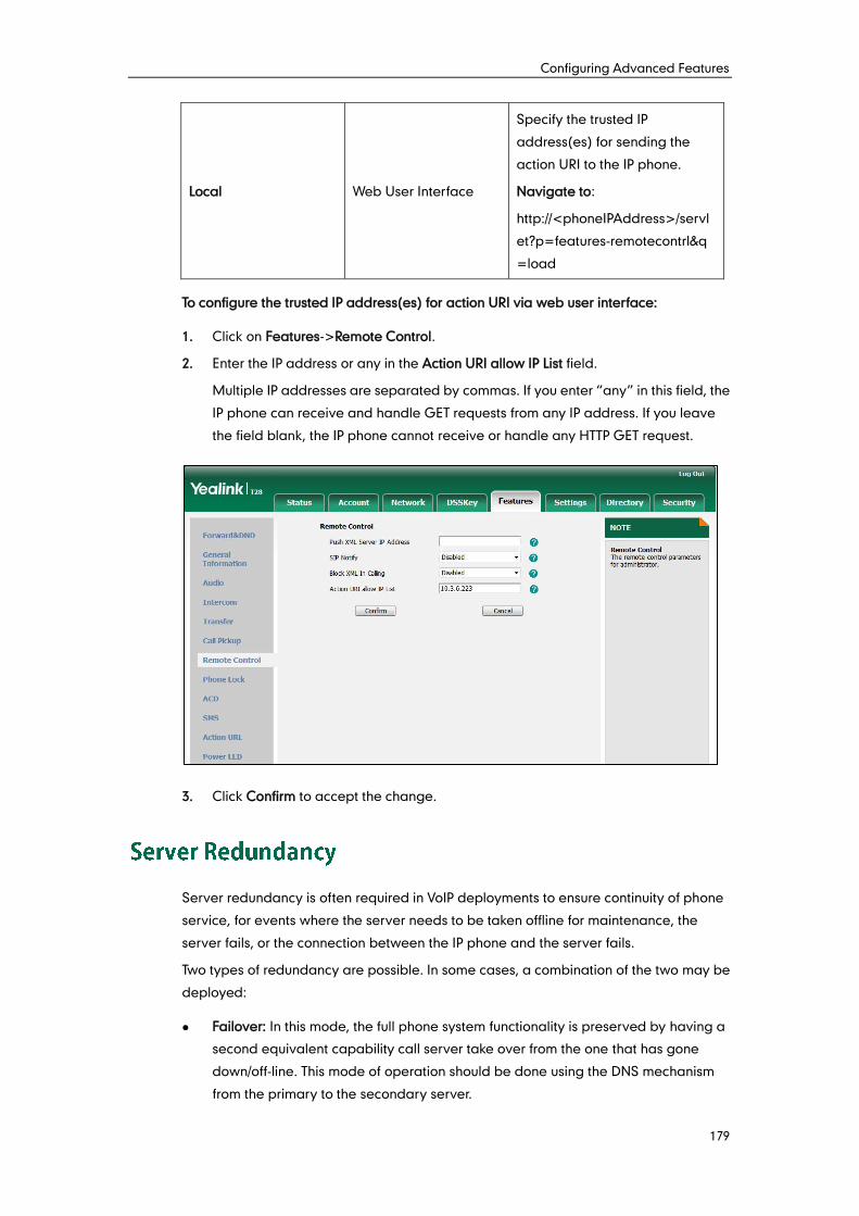
Configuring Advanced Features
179
Local Web User Interface
Specify the trusted IP
address(es) for sending the
action URI to the IP phone.
Navigate to:
http://<phoneIPAddress>/servl
et?p=features-remotecontrl&q
=load
To configure the trusted IP address(es) for action URI via web user interface:
1. Click on Features->Remote Control.
2. Enter the IP address or any in the Action URI allow IP List field.
Multiple IP addresses are separated by commas. If you enter “any” in this field, the
IP phone can receive and handle GET requests from any IP address. If you leave
the field blank, the IP phone cannot receive or handle any HTTP GET request.
3. Click Confirm to accept the change.
Server redundancy is often required in VoIP deployments to ensure continuity of phone
service, for events where the server needs to be taken offline for maintenance, the
server fails, or the connection between the IP phone and the server fails.
Two types of redundancy are possible. In some cases, a combination of the two may be
deployed:
Failover: In this mode, the full phone system functionality is preserved by having a
second equivalent capability call server take over from the one that has gone
down/off-line. This mode of operation should be done using the DNS mechanism
from the primary to the secondary server.
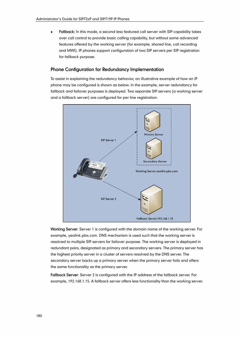
Administrator’s Guide for SIP-T2xP and SIP-T19P IP Phones
180
Fallback: In this mode, a second less featured call server with SIP capability takes
over call control to provide basic calling capability, but without some advanced
features offered by the working server (for example, shared line, call recording
and MWI). IP phones support configuration of two SIP servers per SIP registration
for fallback purpose.
Phone Configuration for Redundancy Implementation
To assist in explaining the redundancy behavior, an illustrative example of how an IP
phone may be configured is shown as below. In the example, server redundancy for
fallback and failover purposes is deployed. Two separate SIP servers (a working server
and a fallback server) are configured for per line registration.
Working Server: Server 1 is configured with the domain name of the working server. For
example, yealink.pbx.com. DNS mechanism is used such that the working server is
resolved to multiple SIP servers for failover purpose. The working server is deployed in
redundant pairs, designated as primary and secondary servers. The primary server has
the highest priority server in a cluster of servers resolved by the DNS server. The
secondary server backs up a primary server when the primary server fails and offers
the same functionality as the primary server.
Fallback Server: Server 2 is configured with the IP address of the fallback server. For
example, 192.168.1.15. A fallback server offers less functionality than the working server.
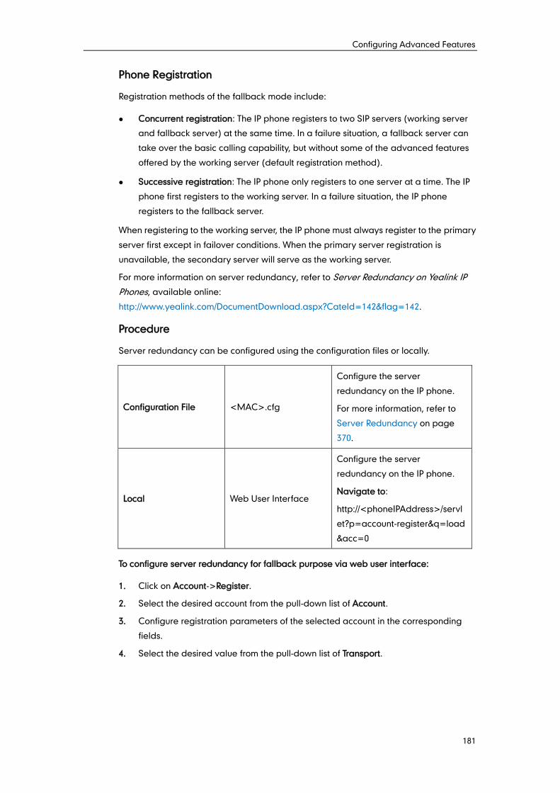
Configuring Advanced Features
181
Phone Registration
Registration methods of the fallback mode include:
Concurrent registration: The IP phone registers to two SIP servers (working server
and fallback server) at the same time. In a failure situation, a fallback server can
take over the basic calling capability, but without some of the advanced features
offered by the working server (default registration method).
Successive registration: The IP phone only registers to one server at a time. The IP
phone first registers to the working server. In a failure situation, the IP phone
registers to the fallback server.
When registering to the working server, the IP phone must always register to the primary
server first except in failover conditions. When the primary server registration is
unavailable, the secondary server will serve as the working server.
For more information on server redundancy, refer to Server Redundancy on Yealink IP
Phones, available online:
http://www.yealink.com/DocumentDownload.aspx?CateId=142&flag=142.
Procedure
Server redundancy can be configured using the configuration files or locally.
Configuration File <MAC>.cfg
Configure the server
redundancy on the IP phone.
For more information, refer to
Server Redundancy on page
370.
Local Web User Interface
Configure the server
redundancy on the IP phone.
Navigate to:
http://<phoneIPAddress>/servl
et?p=account-register&q=load
&acc=0
To configure server redundancy for fallback purpose via web user interface:
1. Click on Account->Register.
2. Select the desired account from the pull-down list of Account.
3. Configure registration parameters of the selected account in the corresponding
fields.
4. Select the desired value from the pull-down list of Transport.
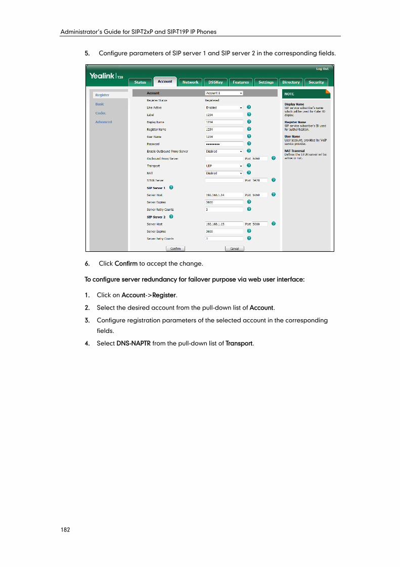
Administrator’s Guide for SIP-T2xP and SIP-T19P IP Phones
182
5. Configure parameters of SIP server 1 and SIP server 2 in the corresponding fields.
6. Click Confirm to accept the change.
To configure server redundancy for failover purpose via web user interface:
1. Click on Account->Register.
2. Select the desired account from the pull-down list of Account.
3. Configure registration parameters of the selected account in the corresponding
fields.
4. Select DNS-NAPTR from the pull-down list of Transport.
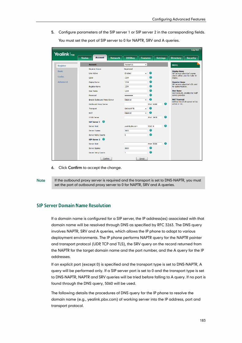
Configuring Advanced Features
183
5. Configure parameters of the SIP server 1 or SIP server 2 in the corresponding fields.
You must set the port of SIP server to 0 for NAPTR, SRV and A queries.
6. Click Confirm to accept the change.
Note
If a domain name is configured for a SIP server, the IP address(es) associated with that
domain name will be resolved through DNS as specified by RFC 3263. The DNS query
involves NAPTR, SRV and A queries, which allows the IP phone to adapt to various
deployment environments. The IP phone performs NAPTR query for the NAPTR pointer
and transport protocol (UDP, TCP and TLS), the SRV query on the record returned from
the NAPTR for the target domain name and the port number, and the A query for the IP
addresses.
If an explicit port (except 0) is specified and the transport type is set to DNS-NAPTR, A
query will be performed only. If a SIP server port is set to 0 and the transport type is set
to DNS-NAPTR, NAPTR and SRV queries will be tried before falling to A query. If no port is
found through the DNS query, 5060 will be used.
The following details the procedures of DNS query for the IP phone to resolve the
domain name (e.g., yealink.pbx.com) of working server into the IP address, port and
transport protocol.
If the outbound proxy server is required and the transport is set to DNS-NAPTR, you must
set the port of outbound proxy server to 0 for NAPTR, SRV and A queries.
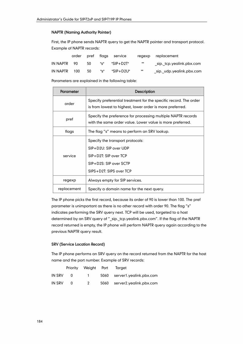
Administrator’s Guide for SIP-T2xP and SIP-T19P IP Phones
184
NAPTR (Naming Authority Pointer)
First, the IP phone sends NAPTR query to get the NAPTR pointer and transport protocol.
Example of NAPTR records:
order pref flags service regexp replacement
IN NAPTR 90 50 "s" "SIP+D2T" "" _sip._tcp.yealink.pbx.com
IN NAPTR 100 50 "s" "SIP+D2U" "" _sip._udp.yealink.pbx.com
Parameters are explained in the following table:
Parameter Description
order Specify preferential treatment for the specific record. The order
is from lowest to highest, lower order is more preferred.
pref Specify the preference for processing multiple NAPTR records
with the same order value. Lower value is more preferred.
flags The flag “s” means to perform an SRV lookup.
service
Specify the transport protocols:
SIP+D2U: SIP over UDP
SIP+D2T: SIP over TCP
SIP+D2S: SIP over SCTP
SIPS+D2T: SIPS over TCP
regexp Always empty for SIP services.
replacement Specify a domain name for the next query.
The IP phone picks the first record, because its order of 90 is lower than 100. The pref
parameter is unimportant as there is no other record with order 90. The flag “s”
indicates performing the SRV query next. TCP will be used, targeted to a host
determined by an SRV query of “_sip._tcp.yealink.pbx.com”. If the flag of the NAPTR
record returned is empty, the IP phone will perform NAPTR query again according to the
previous NAPTR query result.
SRV (Service Location Record)
The IP phone performs an SRV query on the record returned from the NAPTR for the host
name and the port number. Example of SRV records:
Priority Weight Port Target
IN SRV 0 1 5060 server1.yealink.pbx.com
IN SRV 0 2 5060 server2.yealink.pbx.com
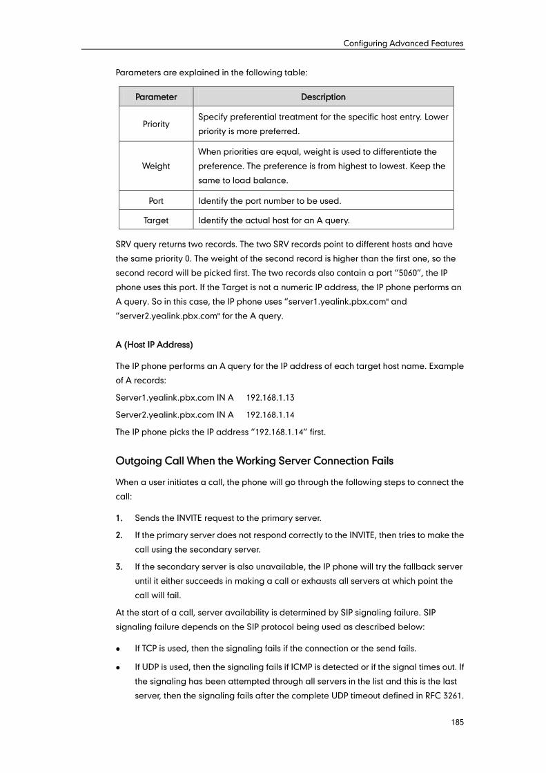
Configuring Advanced Features
185
Parameters are explained in the following table:
Parameter Description
Priority Specify preferential treatment for the specific host entry. Lower
priority is more preferred.
Weight
When priorities are equal, weight is used to differentiate the
preference. The preference is from highest to lowest. Keep the
same to load balance.
Port Identify the port number to be used.
Target Identify the actual host for an A query.
SRV query returns two records. The two SRV records point to different hosts and have
the same priority 0. The weight of the second record is higher than the first one, so the
second record will be picked first. The two records also contain a port “5060”, the IP
phone uses this port. If the Target is not a numeric IP address, the IP phone performs an
A query. So in this case, the IP phone uses “server1.yealink.pbx.com" and
“server2.yealink.pbx.com" for the A query.
A (Host IP Address)
The IP phone performs an A query for the IP address of each target host name. Example
of A records:
Server1.yealink.pbx.com IN A 192.168.1.13
Server2.yealink.pbx.com IN A 192.168.1.14
The IP phone picks the IP address “192.168.1.14” first.
Outgoing Call When the Working Server Connection Fails
When a user initiates a call, the phone will go through the following steps to connect the
call:
1. Sends the INVITE request to the primary server.
2. If the primary server does not respond correctly to the INVITE, then tries to make the
call using the secondary server.
3. If the secondary server is also unavailable, the IP phone will try the fallback server
until it either succeeds in making a call or exhausts all servers at which point the
call will fail.
At the start of a call, server availability is determined by SIP signaling failure. SIP
signaling failure depends on the SIP protocol being used as described below:
If TCP is used, then the signaling fails if the connection or the send fails.
If UDP is used, then the signaling fails if ICMP is detected or if the signal times out. If
the signaling has been attempted through all servers in the list and this is the last
server, then the signaling fails after the complete UDP timeout defined in RFC 3261.
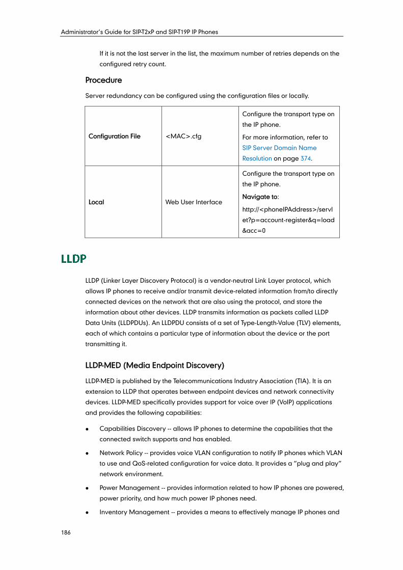
Administrator’s Guide for SIP-T2xP and SIP-T19P IP Phones
186
If it is not the last server in the list, the maximum number of retries depends on the
configured retry count.
Procedure
Server redundancy can be configured using the configuration files or locally.
Configuration File <MAC>.cfg
Configure the transport type on
the IP phone.
For more information, refer to
SIP Server Domain Name
Resolution on page 374.
Local Web User Interface
Configure the transport type on
the IP phone.
Navigate to:
http://<phoneIPAddress>/servl
et?p=account-register&q=load
&acc=0
LLDP (Linker Layer Discovery Protocol) is a vendor-neutral Link Layer protocol, which
allows IP phones to receive and/or transmit device-related information from/to directly
connected devices on the network that are also using the protocol, and store the
information about other devices. LLDP transmits information as packets called LLDP
Data Units (LLDPDUs). An LLDPDU consists of a set of Type-Length-Value (TLV) elements,
each of which contains a particular type of information about the device or the port
transmitting it.
LLDP-MED (Media Endpoint Discovery)
LLDP-MED is published by the Telecommunications Industry Association (TIA). It is an
extension to LLDP that operates between endpoint devices and network connectivity
devices. LLDP-MED specifically provides support for voice over IP (VoIP) applications
and provides the following capabilities:
Capabilities Discovery -- allows IP phones to determine the capabilities that the
connected switch supports and has enabled.
Network Policy -- provides voice VLAN configuration to notify IP phones which VLAN
to use and QoS-related configuration for voice data. It provides a “plug and play”
network environment.
Power Management -- provides information related to how IP phones are powered,
power priority, and how much power IP phones need.
Inventory Management -- provides a means to effectively manage IP phones and
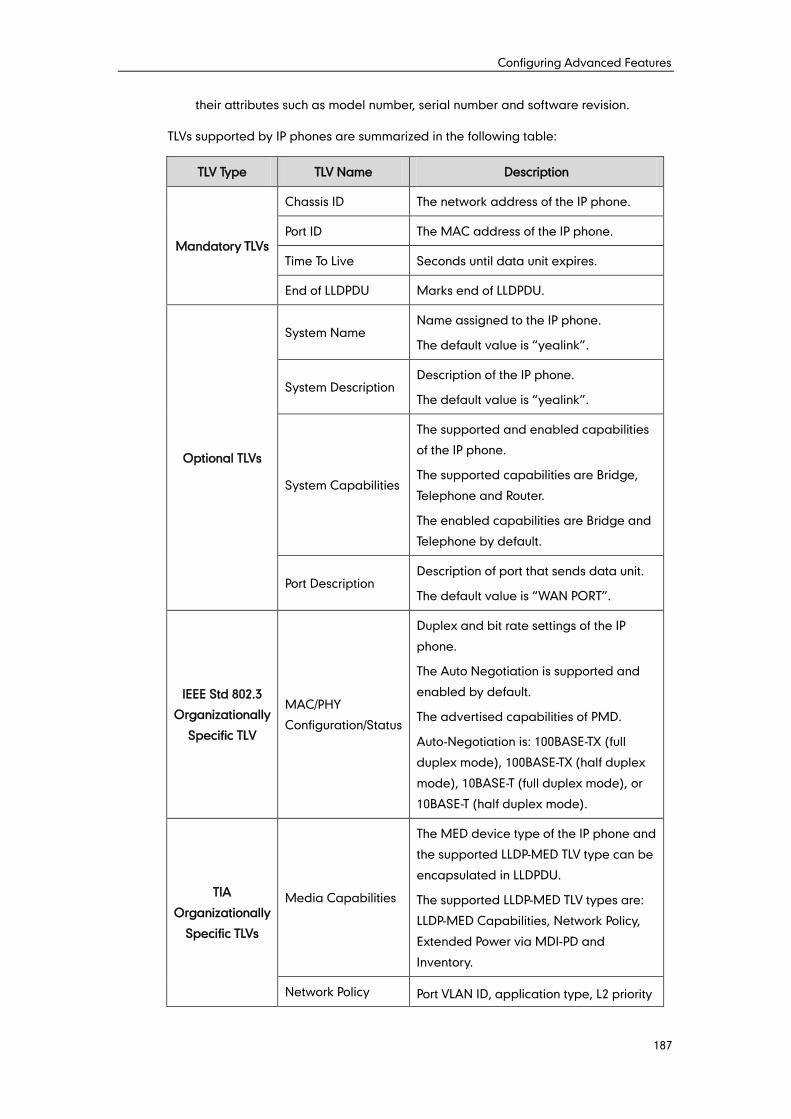
Configuring Advanced Features
187
their attributes such as model number, serial number and software revision.
TLVs supported by IP phones are summarized in the following table:
TLV Type TLV Name Description
Mandatory TLVs
Chassis ID The network address of the IP phone.
Port ID The MAC address of the IP phone.
Time To Live Seconds until data unit expires.
End of LLDPDU Marks end of LLDPDU.
Optional TLVs
System Name Name assigned to the IP phone.
The default value is “yealink”.
System Description Description of the IP phone.
The default value is “yealink”.
System Capabilities
The supported and enabled capabilities
of the IP phone.
The supported capabilities are Bridge,
Telephone and Router.
The enabled capabilities are Bridge and
Telephone by default.
Port Description Description of port that sends data unit.
The default value is “WAN PORT”.
IEEE Std 802.3
Organizationally
Specific TLV
MAC/PHY
Configuration/Status
Duplex and bit rate settings of the IP
phone.
The Auto Negotiation is supported and
enabled by default.
The advertised capabilities of PMD.
Auto-Negotiation is: 100BASE-TX (full
duplex mode), 100BASE-TX (half duplex
mode), 10BASE-T (full duplex mode), or
10BASE-T (half duplex mode).
TIA
Organizationally
Specific TLVs
Media Capabilities
The MED device type of the IP phone and
the supported LLDP-MED TLV type can be
encapsulated in LLDPDU.
The supported LLDP-MED TLV types are:
LLDP-MED Capabilities, Network Policy,
Extended Power via MDI-PD and
Inventory.
Network Policy Port VLAN ID, application type, L2 priority
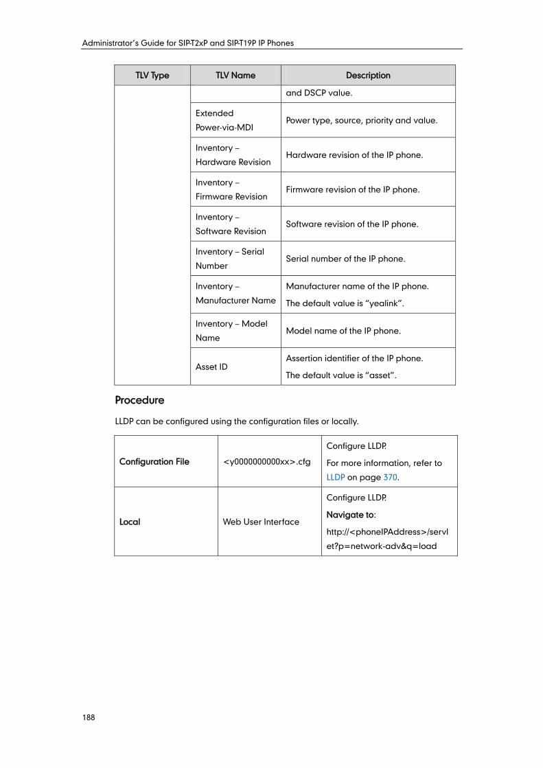
Administrator’s Guide for SIP-T2xP and SIP-T19P IP Phones
188
TLV Type TLV Name Description
and DSCP value.
Extended
Power-via-MDI Power type, source, priority and value.
Inventory –
Hardware Revision Hardware revision of the IP phone.
Inventory –
Firmware Revision Firmware revision of the IP phone.
Inventory –
Software Revision Software revision of the IP phone.
Inventory – Serial
Number Serial number of the IP phone.
Inventory –
Manufacturer Name
Manufacturer name of the IP phone.
The default value is “yealink”.
Inventory – Model
Name Model name of the IP phone.
Asset ID Assertion identifier of the IP phone.
The default value is “asset”.
Procedure
LLDP can be configured using the configuration files or locally.
Configuration File <y0000000000xx>.cfg
Configure LLDP.
For more information, refer to
LLDP on page 370.
Local Web User Interface
Configure LLDP.
Navigate to:
http://<phoneIPAddress>/servl
et?p=network-adv&q=load
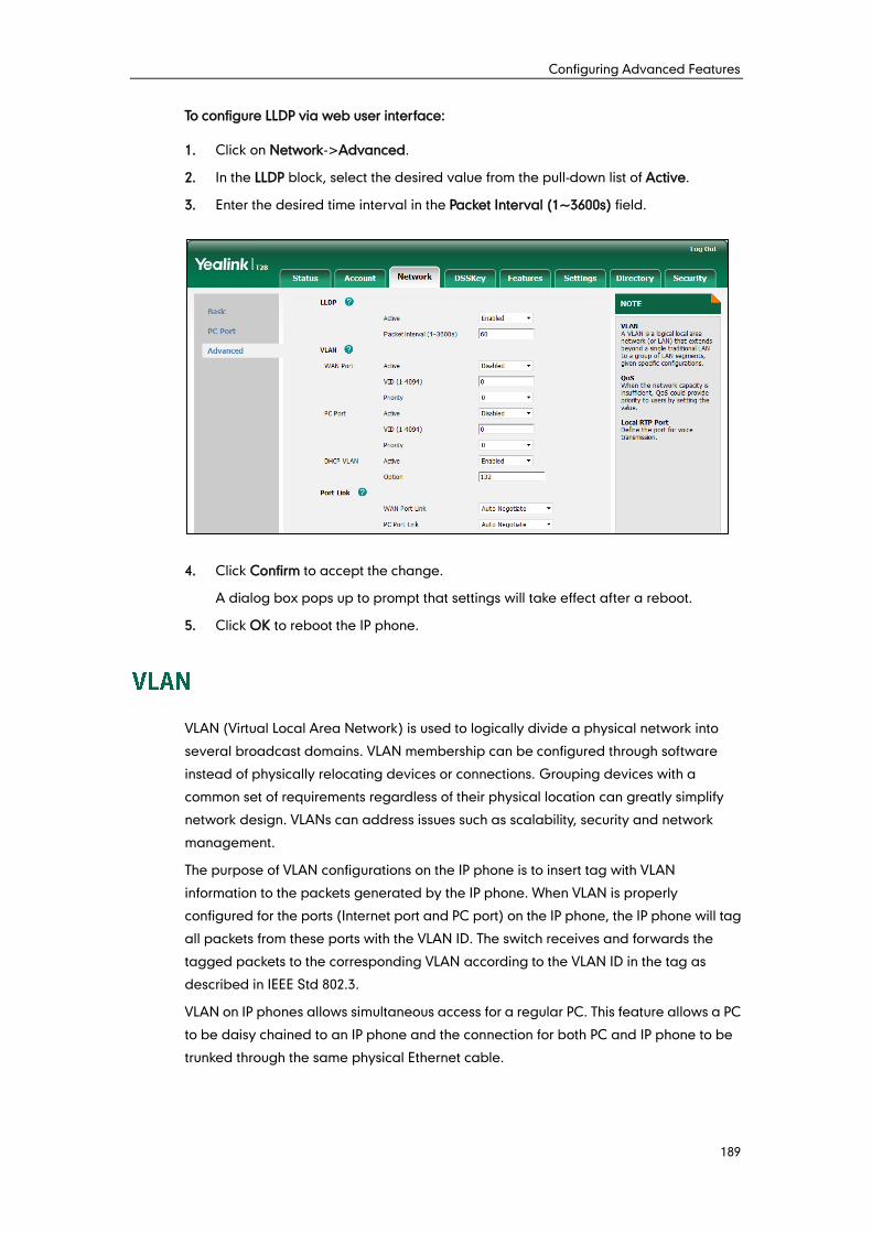
Configuring Advanced Features
189
To configure LLDP via web user interface:
1. Click on Network->Advanced.
2. In the LLDP block, select the desired value from the pull-down list of Active.
3. Enter the desired time interval in the Packet Interval (1~3600s) field.
4. Click Confirm to accept the change.
A dialog box pops up to prompt that settings will take effect after a reboot.
5. Click OK to reboot the IP phone.
VLAN (Virtual Local Area Network) is used to logically divide a physical network into
several broadcast domains. VLAN membership can be configured through software
instead of physically relocating devices or connections. Grouping devices with a
common set of requirements regardless of their physical location can greatly simplify
network design. VLANs can address issues such as scalability, security and network
management.
The purpose of VLAN configurations on the IP phone is to insert tag with VLAN
information to the packets generated by the IP phone. When VLAN is properly
configured for the ports (Internet port and PC port) on the IP phone, the IP phone will tag
all packets from these ports with the VLAN ID. The switch receives and forwards the
tagged packets to the corresponding VLAN according to the VLAN ID in the tag as
described in IEEE Std 802.3.
VLAN on IP phones allows simultaneous access for a regular PC. This feature allows a PC
to be daisy chained to an IP phone and the connection for both PC and IP phone to be
trunked through the same physical Ethernet cable.
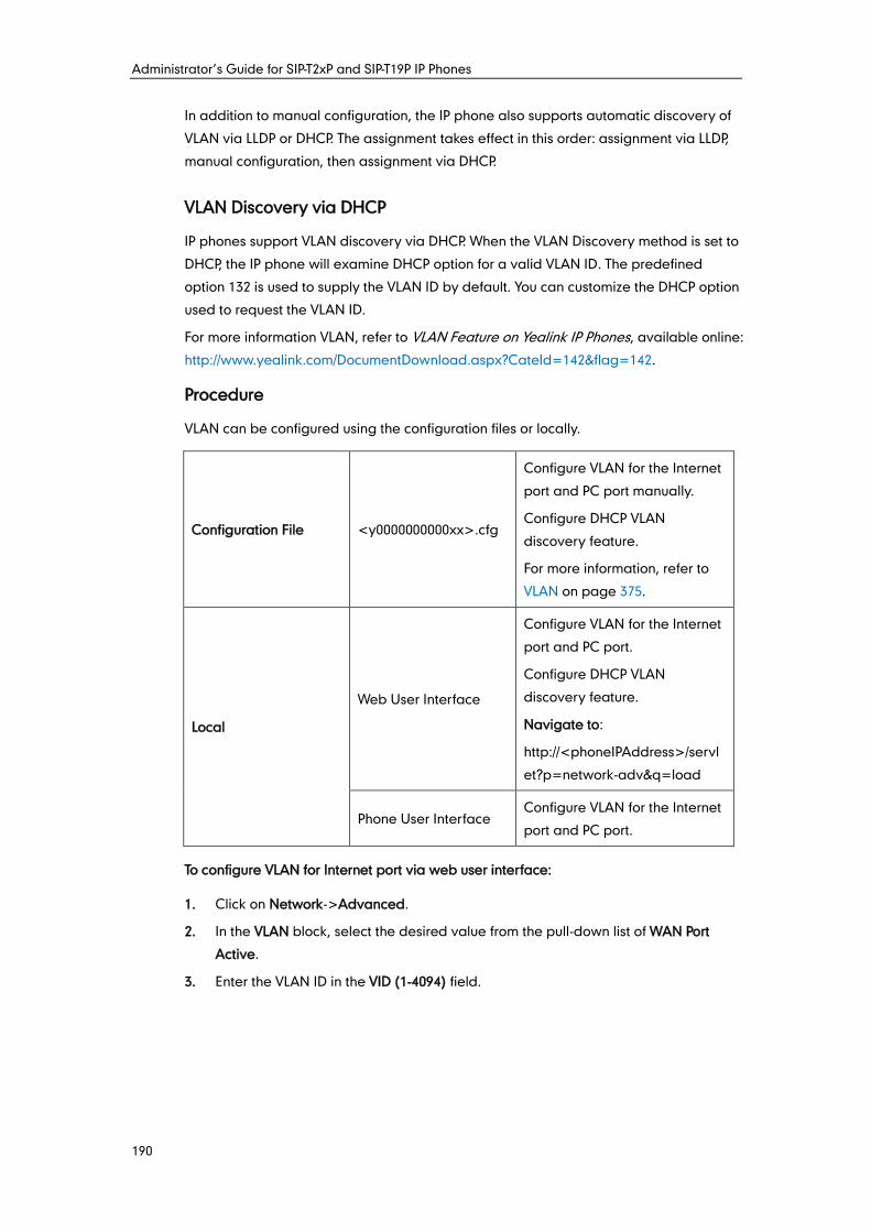
Administrator’s Guide for SIP-T2xP and SIP-T19P IP Phones
190
In addition to manual configuration, the IP phone also supports automatic discovery of
VLAN via LLDP or DHCP. The assignment takes effect in this order: assignment via LLDP,
manual configuration, then assignment via DHCP.
VLAN Discovery via DHCP
IP phones support VLAN discovery via DHCP. When the VLAN Discovery method is set to
DHCP, the IP phone will examine DHCP option for a valid VLAN ID. The predefined
option 132 is used to supply the VLAN ID by default. You can customize the DHCP option
used to request the VLAN ID.
For more information VLAN, refer to VLAN Feature on Yealink IP Phones, available online:
http://www.yealink.com/DocumentDownload.aspx?CateId=142&flag=142.
Procedure
VLAN can be configured using the configuration files or locally.
Configuration File <y0000000000xx>.cfg
Configure VLAN for the Internet
port and PC port manually.
Configure DHCP VLAN
discovery feature.
For more information, refer to
VLAN on page 375.
Local
Web User Interface
Configure VLAN for the Internet
port and PC port.
Configure DHCP VLAN
discovery feature.
Navigate to:
http://<phoneIPAddress>/servl
et?p=network-adv&q=load
Phone User Interface Configure VLAN for the Internet
port and PC port.
To configure VLAN for Internet port via web user interface:
1. Click on Network->Advanced.
2. In the VLAN block, select the desired value from the pull-down list of WAN Port
Active.
3. Enter the VLAN ID in the VID (1-4094) field.
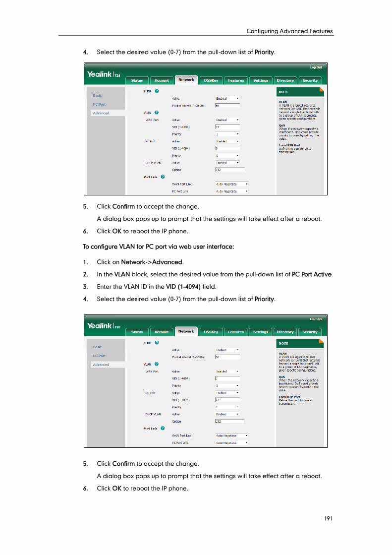
Configuring Advanced Features
191
4. Select the desired value (0-7) from the pull-down list of Priority.
5. Click Confirm to accept the change.
A dialog box pops up to prompt that the settings will take effect after a reboot.
6. Click OK to reboot the IP phone.
To configure VLAN for PC port via web user interface:
1. Click on Network->Advanced.
2. In the VLAN block, select the desired value from the pull-down list of PC Port Active.
3. Enter the VLAN ID in the VID (1-4094) field.
4. Select the desired value (0-7) from the pull-down list of Priority.
5. Click Confirm to accept the change.
A dialog box pops up to prompt that the settings will take effect after a reboot.
6. Click OK to reboot the IP phone.
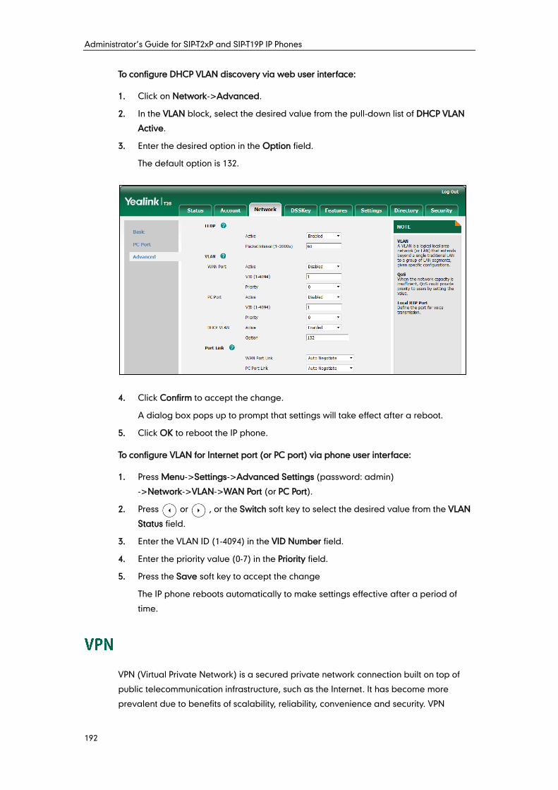
Administrator’s Guide for SIP-T2xP and SIP-T19P IP Phones
192
To configure DHCP VLAN discovery via web user interface:
1. Click on Network->Advanced.
2. In the VLAN block, select the desired value from the pull-down list of DHCP VLAN
Active.
3. Enter the desired option in the Option field.
The default option is 132.
4. Click Confirm to accept the change.
A dialog box pops up to prompt that settings will take effect after a reboot.
5. Click OK to reboot the IP phone.
To configure VLAN for Internet port (or PC port) via phone user interface:
1. Press Menu->Settings->Advanced Settings (password: admin)
->Network->VLAN->WAN Port (or PC Port).
2. Press or , or the Switch soft key to select the desired value from the VLAN
Status field.
3. Enter the VLAN ID (1-4094) in the VID Number field.
4. Enter the priority value (0-7) in the Priority field.
5. Press the Save soft key to accept the change
The IP phone reboots automatically to make settings effective after a period of
time.
VPN (Virtual Private Network) is a secured private network connection built on top of
public telecommunication infrastructure, such as the Internet. It has become more
prevalent due to benefits of scalability, reliability, convenience and security. VPN
Configuring Advanced Features
193
provides remote offices or individual users with secure access to their organization's
network. There are two types of VPN access: remote-access VPN (connecting an
individual device to a network) and site-to-site VPN (connecting two networks together).
Remote-access VPN allows employees to access their company's intranet from home or
outside the office, and site-to-site VPN allows employees in geographically separated
offices to share one cohesive virtual network. VPN can be also classified by the
protocols used to tunnel the traffic. It provides security through tunneling protocols:
IPSec, SSL, L2TP and PPTP.
IP phones support SSL VPN, which provides remote-access VPN capabilities through SSL.
OpenVPN is a full featured SSL VPN software solution that creates secure connections in
remote access facilities, designed to work with the TUN/TAP virtual network interface.
TUN and TAP are virtual network kernel devices. TAP simulates a link layer device and
provides a virtual point-to-point connection, while TUN simulates a network layer device
and provides a virtual network segment. IP phones use OpenVPN to achieve VPN
feature. To prevent disclosure of private information, tunnel endpoints must authenticate
each other before secure VPN tunnel is established. After VPN feature is configured
properly on the IP phone, the IP phone acts as a VPN client and uses the certificates to
authenticate the VPN server.
To use VPN, the compressed package of VPN-related files should be uploaded to the IP
phone in advance. The file format of the compressed package must be *.tar. For
SIP-T28/T26P/T22P IP phones, the maximum file size is 100KB. For SIP-T21P/T19P IP phones,
the maximum file size is 200KB. The related VPN files are: certificates (ca.crt and
client.crt), key (client.key) and the configuration file (vpn.cnf) of the VPN client. For more
information on how to package a TAR file, refer to OpenVPN Feature on Yealink IP
Phones, available online:
http://www.yealink.com/DocumentDownload.aspx?CateId=142&flag=142.
Note
Procedure
VPN can be configured using the configuration files or locally.
Configuration File <y0000000000xx>.cfg
Configure VPN feature and
upload a TAR file to the IP
phone.
For more information, refer to
VPN on page 379.
Local Web User Interface
Configure VPN feature and
upload a TAR package to the IP
phone.
Navigate to:
http://<phoneIPAddress>/servl
VPN feature is not applicable to SIP-T19P IP phones.
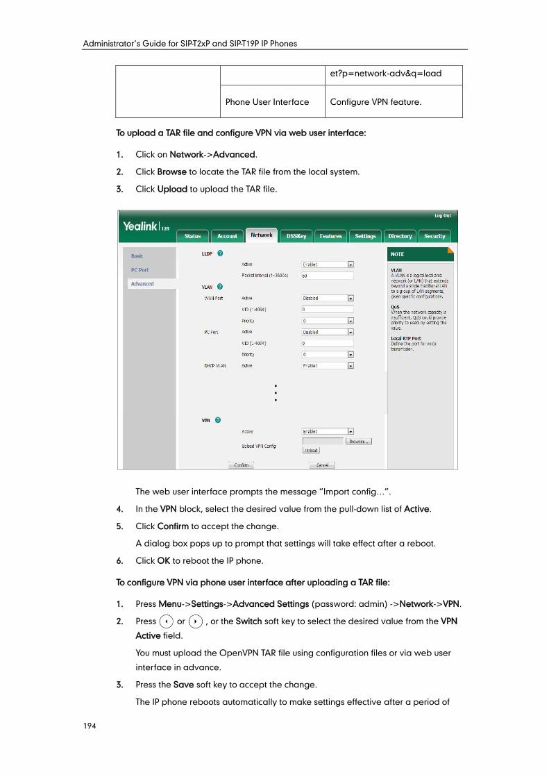
Administrator’s Guide for SIP-T2xP and SIP-T19P IP Phones
194
et?p=network-adv&q=load
Phone User Interface Configure VPN feature.
To upload a TAR file and configure VPN via web user interface:
1. Click on Network->Advanced.
2. Click Browse to locate the TAR file from the local system.
3. Click Upload to upload the TAR file.
The web user interface prompts the message “Import config…”.
4. In the VPN block, select the desired value from the pull-down list of Active.
5. Click Confirm to accept the change.
A dialog box pops up to prompt that settings will take effect after a reboot.
6. Click OK to reboot the IP phone.
To configure VPN via phone user interface after uploading a TAR file:
1. Press Menu->Settings->Advanced Settings (password: admin) ->Network->VPN.
2. Press or , or the Switch soft key to select the desired value from the VPN
Active field.
You must upload the OpenVPN TAR file using configuration files or via web user
interface in advance.
3. Press the Save soft key to accept the change.
The IP phone reboots automatically to make settings effective after a period of
Configuring Advanced Features
195
time.
Quality of Service (QoS) is the ability to provide different priorities for different packets
in the network, allowing the transport of traffic with special requirements. QoS
guarantees are important for applications that require fixed bit rate and are delay
sensitive when the network capacity is insufficient. There are four major QoS factors to
be considered when configuring a modern QoS implementation: bandwidth, delay,
jitter and loss.
QoS provides better network service through the following features:
Supporting dedicated bandwidth
Improving loss characteristics
Avoiding and managing network congestion
Shaping network traffic
Setting traffic priorities across the network
The Best-Effort service is the default QoS model in IP networks. It provides no
guarantees for data delivering, which means delay, jitter, packet loss and bandwidth
allocation are unpredictable. Differentiated Services (DiffServ or DS) is the most widely
used QoS model. It provides a simple and scalable mechanism for classifying and
managing network traffic and providing QoS on modern IP networks. Differentiated
Services Code Point (DSCP) is used to define DiffServ classes and stored in the first six
bits of the ToS (Type of Service) field. Each router on the network can provide QoS
simply based on the DiffServ class. The DSCP value ranges from 0 to 63 with each DSCP
specifying a particular per-hop behavior (PHB) applicable to a packet. A PHB refers to
the packet scheduling, queuing, policing, or shaping behavior of a node on any given
packet.
Four standard PHBs available to construct a DiffServ-enabled network and achieve
QoS:
Class Selector PHB -- backwards compatible with IP precedence. Class Selector
code points are of the form “xxx000”. The first three bits are the IP precedence bits.
These class selector PHBs retain almost the same forwarding behavior as nodes
that implement IP precedence-based classification and forwarding.
Expedited Forwarding PHB -- the key ingredient in DiffServ model for providing a
low-loss, low-latency, low-jitter and assured bandwidth service.
Assured Forwarding PHB -- defines a method by which BAs (Bandwidth Allocations)
can be given different forwarding assurances.
Default PHB -- specifies that a packet marked with a DSCP value of “000000” gets
the traditional best effort service from a DS-compliant node.
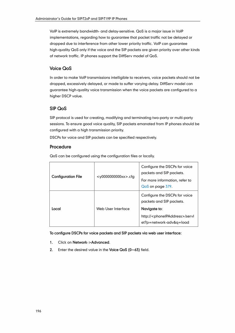
Administrator’s Guide for SIP-T2xP and SIP-T19P IP Phones
196
VoIP is extremely bandwidth- and delay-sensitive. QoS is a major issue in VoIP
implementations, regarding how to guarantee that packet traffic not be delayed or
dropped due to interference from other lower priority traffic. VoIP can guarantee
high-quality QoS only if the voice and the SIP packets are given priority over other kinds
of network traffic. IP phones support the DiffServ model of QoS.
Voice QoS
In order to make VoIP transmissions intelligible to receivers, voice packets should not be
dropped, excessively delayed, or made to suffer varying delay. DiffServ model can
guarantee high-quality voice transmission when the voice packets are configured to a
higher DSCP value.
SIP QoS
SIP protocol is used for creating, modifying and terminating two-party or multi-party
sessions. To ensure good voice quality, SIP packets emanated from IP phones should be
configured with a high transmission priority.
DSCPs for voice and SIP packets can be specified respectively.
Procedure
QoS can be configured using the configuration files or locally.
Configuration File <y0000000000xx>.cfg
Configure the DSCPs for voice
packets and SIP packets.
For more information, refer to
QoS on page 379.
Local Web User Interface
Configure the DSCPs for voice
packets and SIP packets.
Navigate to:
http://<phoneIPAddress>/servl
et?p=network-adv&q=load
To configure DSCPs for voice packets and SIP packets via web user interface:
1. Click on Network->Advanced.
2. Enter the desired value in the Voice QoS (0~63) field.
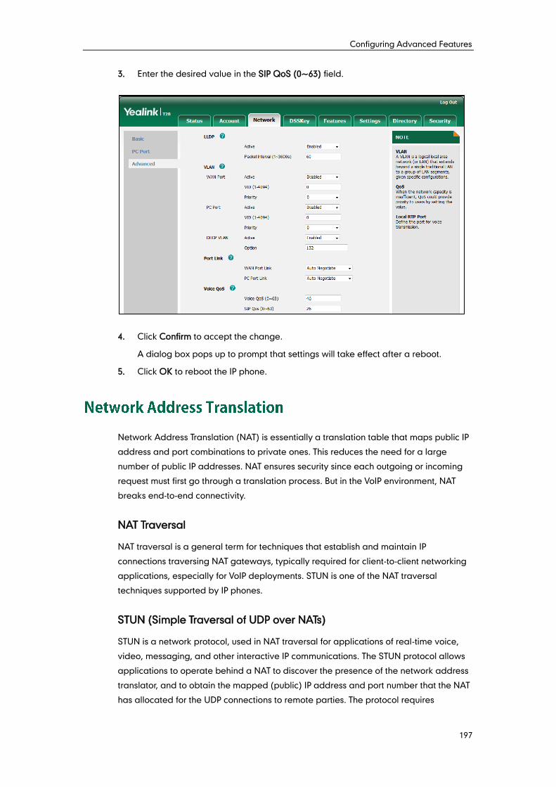
Configuring Advanced Features
197
3. Enter the desired value in the SIP QoS (0~63) field.
4. Click Confirm to accept the change.
A dialog box pops up to prompt that settings will take effect after a reboot.
5. Click OK to reboot the IP phone.
Network Address Translation (NAT) is essentially a translation table that maps public IP
address and port combinations to private ones. This reduces the need for a large
number of public IP addresses. NAT ensures security since each outgoing or incoming
request must first go through a translation process. But in the VoIP environment, NAT
breaks end-to-end connectivity.
NAT Traversal
NAT traversal is a general term for techniques that establish and maintain IP
connections traversing NAT gateways, typically required for client-to-client networking
applications, especially for VoIP deployments. STUN is one of the NAT traversal
techniques supported by IP phones.
STUN (Simple Traversal of UDP over NATs)
STUN is a network protocol, used in NAT traversal for applications of real-time voice,
video, messaging, and other interactive IP communications. The STUN protocol allows
applications to operate behind a NAT to discover the presence of the network address
translator, and to obtain the mapped (public) IP address and port number that the NAT
has allocated for the UDP connections to remote parties. The protocol requires
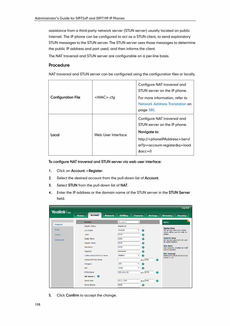
Administrator’s Guide for SIP-T2xP and SIP-T19P IP Phones
198
assistance from a third-party network server (STUN server) usually located on public
Internet. The IP phone can be configured to act as a STUN client, to send exploratory
STUN messages to the STUN server. The STUN server uses those messages to determine
the public IP address and port used, and then informs the client.
The NAT traversal and STUN server are configurable on a per-line basis.
Procedure
NAT traversal and STUN server can be configured using the configuration files or locally.
Configuration File <MAC>.cfg
Configure NAT traversal and
STUN server on the IP phone.
For more information, refer to
Network Address Translation on
page 380.
Local Web User Interface
Configure NAT traversal and
STUN server on the IP phone.
Navigate to:
http://<phoneIPAddress>/servl
et?p=account-register&q=load
&acc=0
To configure NAT traversal and STUN server via web user interface:
1. Click on Account->Register.
2. Select the desired account from the pull-down list of Account.
3. Select STUN from the pull-down list of NAT.
4. Enter the IP address or the domain name of the STUN server in the STUN Server
field.
5. Click Confirm to accept the change.
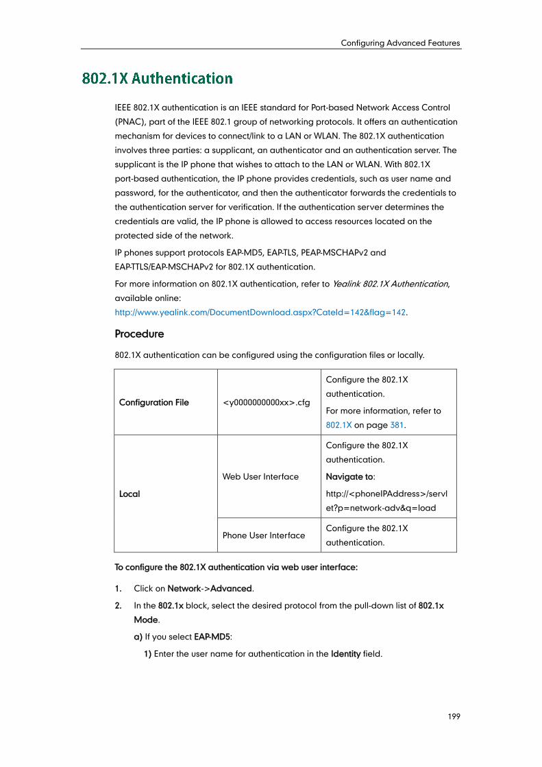
Configuring Advanced Features
199
IEEE 802.1X authentication is an IEEE standard for Port-based Network Access Control
(PNAC), part of the IEEE 802.1 group of networking protocols. It offers an authentication
mechanism for devices to connect/link to a LAN or WLAN. The 802.1X authentication
involves three parties: a supplicant, an authenticator and an authentication server. The
supplicant is the IP phone that wishes to attach to the LAN or WLAN. With 802.1X
port-based authentication, the IP phone provides credentials, such as user name and
password, for the authenticator, and then the authenticator forwards the credentials to
the authentication server for verification. If the authentication server determines the
credentials are valid, the IP phone is allowed to access resources located on the
protected side of the network.
IP phones support protocols EAP-MD5, EAP-TLS, PEAP-MSCHAPv2 and
EAP-TTLS/EAP-MSCHAPv2 for 802.1X authentication.
For more information on 802.1X authentication, refer to Yealink 802.1X Authentication,
available online:
http://www.yealink.com/DocumentDownload.aspx?CateId=142&flag=142.
Procedure
802.1X authentication can be configured using the configuration files or locally.
Configuration File <y0000000000xx>.cfg
Configure the 802.1X
authentication.
For more information, refer to
802.1X on page 381.
Local
Web User Interface
Configure the 802.1X
authentication.
Navigate to:
http://<phoneIPAddress>/servl
et?p=network-adv&q=load
Phone User Interface Configure the 802.1X
authentication.
To configure the 802.1X authentication via web user interface:
1. Click on Network->Advanced.
2. In the 802.1x block, select the desired protocol from the pull-down list of 802.1x
Mode.
a) If you select EAP-MD5:
1) Enter the user name for authentication in the Identity field.
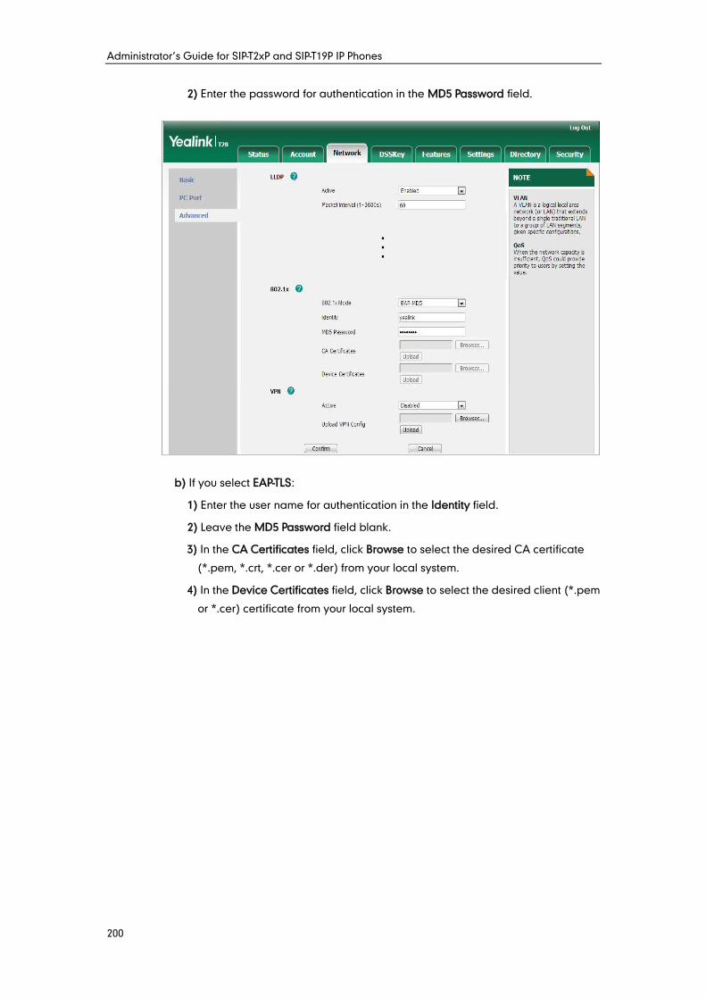
Administrator’s Guide for SIP-T2xP and SIP-T19P IP Phones
200
2) Enter the password for authentication in the MD5 Password field.
b) If you select EAP-TLS:
1) Enter the user name for authentication in the Identity field.
2) Leave the MD5 Password field blank.
3) In the CA Certificates field, click Browse to select the desired CA certificate
(*.pem, *.crt, *.cer or *.der) from your local system.
4) In the Device Certificates field, click Browse to select the desired client (*.pem
or *.cer) certificate from your local system.
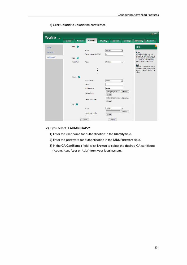
Configuring Advanced Features
201
5) Click Upload to upload the certificates.
c) If you select PEAP-MSCHAPv2:
1) Enter the user name for authentication in the Identity field.
2) Enter the password for authentication in the MD5 Password field.
3) In the CA Certificates field, click Browse to select the desired CA certificate
(*.pem, *.crt, *.cer or *.der) from your local system.
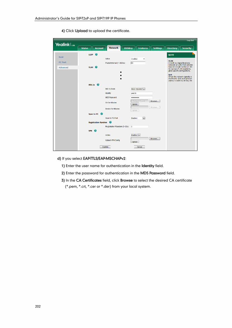
Administrator’s Guide for SIP-T2xP and SIP-T19P IP Phones
202
4) Click Upload to upload the certificate.
d) If you select EAP-TTLS/EAP-MSCHAPv2:
1) Enter the user name for authentication in the Identity field.
2) Enter the password for authentication in the MD5 Password field.
3) In the CA Certificates field, click Browse to select the desired CA certificate
(*.pem, *.crt, *.cer or *.der) from your local system.
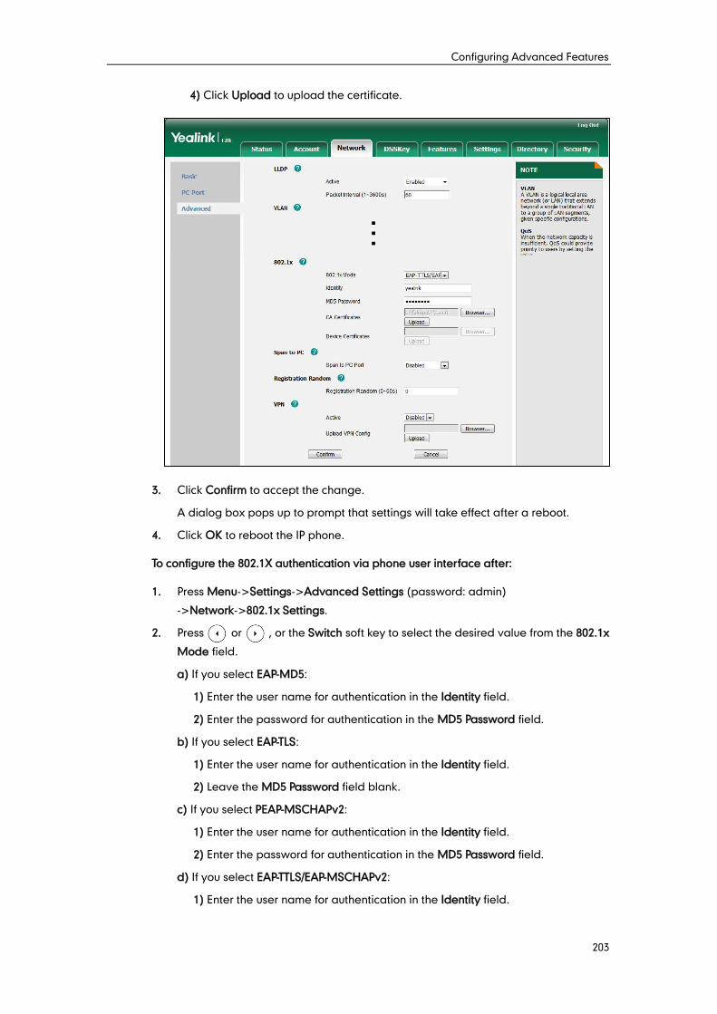
Configuring Advanced Features
203
4) Click Upload to upload the certificate.
3. Click Confirm to accept the change.
A dialog box pops up to prompt that settings will take effect after a reboot.
4. Click OK to reboot the IP phone.
To configure the 802.1X authentication via phone user interface after:
1. Press Menu->Settings->Advanced Settings (password: admin)
->Network->802.1x Settings.
2. Press or , or the Switch soft key to select the desired value from the 802.1x
Mode field.
a) If you select EAP-MD5:
1) Enter the user name for authentication in the Identity field.
2) Enter the password for authentication in the MD5 Password field.
b) If you select EAP-TLS:
1) Enter the user name for authentication in the Identity field.
2) Leave the MD5 Password field blank.
c) If you select PEAP-MSCHAPv2:
1) Enter the user name for authentication in the Identity field.
2) Enter the password for authentication in the MD5 Password field.
d) If you select EAP-TTLS/EAP-MSCHAPv2:
1) Enter the user name for authentication in the Identity field.
Administrator’s Guide for SIP-T2xP and SIP-T19P IP Phones
204
2) Enter the password for authentication in the MD5 Password field.
3. Click Save to accept the change.
The IP phone reboots automatically to make the settings effective after a period of
time.
TR-069 is a technical specification defined by the Broadband Forum, which defines a
mechanism that encompasses secure auto-configuration of a CPE (Customer-Premises
Equipment), and incorporates other CPE management functions into a common
framework. TR-069 uses common transport mechanisms (HTTP and HTTPS) for
communication between CPE and ACS (Auto Configuration Servers). The HTTP(S)
messages contain XML-RPC methods defined in the standard for configuration and
management of the CPE.
TR-069 is intended to support a variety of functionalities to manage a collection of CPEs,
including the following primary capabilities:
Auto-configuration and dynamic service provisioning
Software or firmware image management
Status and performance monitoring
Diagnostics
The following table provides a description of RPC methods supported by IP phones.
RPC Method Description
GetRPCMethods This method is used to discover the set of methods
supported by the CPE.
SetParameterValues This method is used to modify the value of one or
more CPE parameters.
GetParameterValues This method is used to obtain the value of one or
more CPE parameters.
GetParameterNames This method is used to discover the parameters
accessible on a particular CPE.
GetParameterAttributes This method is used to read the attributes associated
with one or more CPE parameters.
SetParameterAttributes This method is used to modify attributes associated
with one or more CPE parameters.
Reboot This method causes the CPE to reboot.
Download This method is used to cause the CPE to download a
specified file from the designated location.
Configuring Advanced Features
205
RPC Method Description
File types supported by IP phones are:
Firmware Image
Configuration File
Upload
This method is used to cause the CPE to upload a
specified file to the designated location.
File types supported by IP phones are:
Configuration File
Log File
ScheduleInform
This method is used to request the CPE to schedule a
one-time Inform method call (separate from its
periodic Inform method calls) sometime in the future.
FactoryReset This method resets the CPE to its factory default state.
TransferComplete
This method informs the ACS of the completion
(either successful or unsuccessful) of a file transfer
initiated by an earlier Download or Upload method
call.
AddObject This method is used to add a new instance of an
object defined on the CPE.
DeleteObject This method is used to remove a particular instance
of an object.
For more information on TR-069, refer to Yealink TR-069 Technote, available online:
http://www.yealink.com/DocumentDownload.aspx?CateId=142&flag=142.
Procedure
TR-069 can be configured using the configuration files or locally.
Configuration File <y0000000000xx>.cfg
Configure TR-069 feature.
For more information, refer to
TR-069 on page 383.
Local Web User Interface
Configure TR-069 feature.
Navigate to:
http://<phoneIPAddress>/servl
et?p=settings-preference&q=lo
ad
To configure TR-069 via web user interface:
1. Click on Settings->TR069.
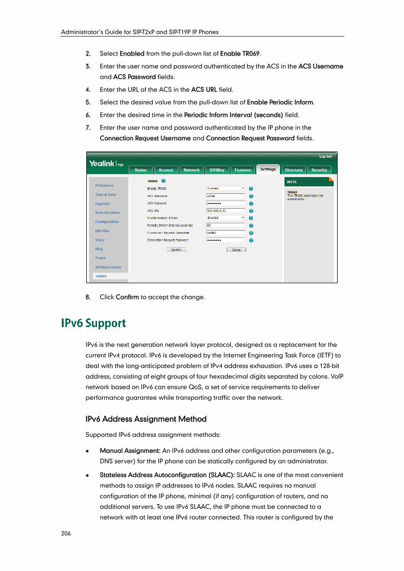
Administrator’s Guide for SIP-T2xP and SIP-T19P IP Phones
206
2. Select Enabled from the pull-down list of Enable TR069.
3. Enter the user name and password authenticated by the ACS in the ACS Username
and ACS Password fields.
4. Enter the URL of the ACS in the ACS URL field.
5. Select the desired value from the pull-down list of Enable Periodic Inform.
6. Enter the desired time in the Periodic Inform Interval (seconds) field.
7. Enter the user name and password authenticated by the IP phone in the
Connection Request Username and Connection Request Password fields.
8. Click Confirm to accept the change.
IPv6 is the next generation network layer protocol, designed as a replacement for the
current IPv4 protocol. IPv6 is developed by the Internet Engineering Task Force (IETF) to
deal with the long-anticipated problem of IPv4 address exhaustion. IPv6 uses a 128-bit
address, consisting of eight groups of four hexadecimal digits separated by colons. VoIP
network based on IPv6 can ensure QoS, a set of service requirements to deliver
performance guarantee while transporting traffic over the network.
IPv6 Address Assignment Method
Supported IPv6 address assignment methods:
Manual Assignment: An IPv6 address and other configuration parameters (e.g.,
DNS server) for the IP phone can be statically configured by an administrator.
Stateless Address Autoconfiguration (SLAAC): SLAAC is one of the most convenient
methods to assign IP addresses to IPv6 nodes. SLAAC requires no manual
configuration of the IP phone, minimal (if any) configuration of routers, and no
additional servers. To use IPv6 SLAAC, the IP phone must be connected to a
network with at least one IPv6 router connected. This router is configured by the
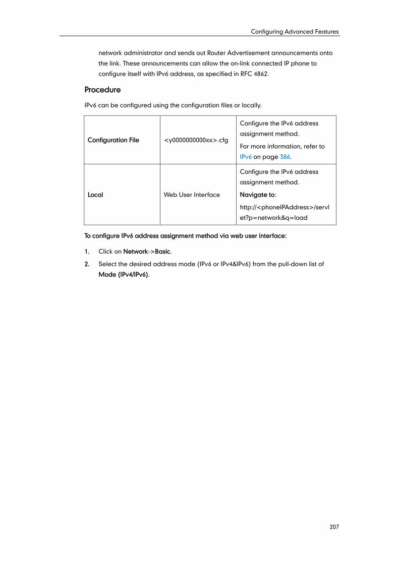
Configuring Advanced Features
207
network administrator and sends out Router Advertisement announcements onto
the link. These announcements can allow the on-link connected IP phone to
configure itself with IPv6 address, as specified in RFC 4862.
Procedure
IPv6 can be configured using the configuration files or locally.
Configuration File <y0000000000xx>.cfg
Configure the IPv6 address
assignment method.
For more information, refer to
IPv6 on page 386.
Local Web User Interface
Configure the IPv6 address
assignment method.
Navigate to:
http://<phoneIPAddress>/servl
et?p=network&q=load
To configure IPv6 address assignment method via web user interface:
1. Click on Network->Basic.
2. Select the desired address mode (IPv6 or IPv4&IPv6) from the pull-down list of
Mode (IPv4/IPv6).
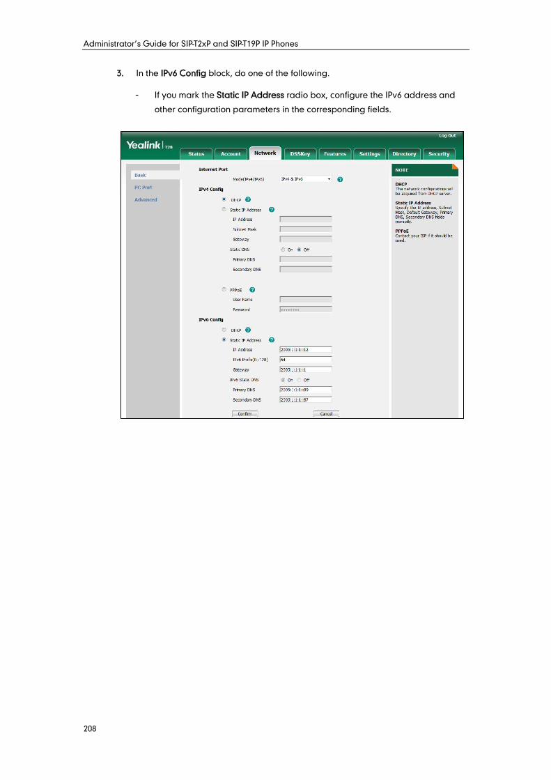
Administrator’s Guide for SIP-T2xP and SIP-T19P IP Phones
208
3. In the IPv6 Config block, do one of the following.
- If you mark the Static IP Address radio box, configure the IPv6 address and
other configuration parameters in the corresponding fields.
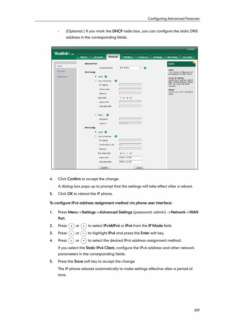
Configuring Advanced Features
209
- (Optional.) If you mark the DHCP radio box, you can configure the static DNS
address in the corresponding fields.
4. Click Confirm to accept the change.
A dialog box pops up to prompt that the settings will take effect after a reboot.
5. Click OK to reboot the IP phone.
To configure IPv6 address assignment method via phone user interface:
1. Press Menu->Settings->Advanced Settings (password: admin) ->Network->WAN
Port.
2. Press or to select IPv4&IPv6 or IPv6 from the IP Mode field.
3. Press or to highlight IPv6 and press the Enter soft key.
4. Press or to select the desired IPv6 address assignment method.
If you select the Static IPv6 Client, configure the IPv6 address and other network
parameters in the corresponding fields.
5. Press the Save soft key to accept the change
The IP phone reboots automatically to make settings effective after a period of
time.

Administrator’s Guide for SIP-T2xP and SIP-T19P IP Phones
210
Configuring Audio Features
211
This chapter provides information for making configuration changes for the following
audio features:
Headset Prior
Dual Headset
Audio Codecs
Acoustic Clarity Technology
Headset prior allows users to use headset preferentially if a headset is physically
connected to the IP phone. This feature is especially useful for permanent or full-time
headset users.
Procedure
Headset prior can be configured using the configuration files or locally.
Configuration File <y0000000000xx>.cfg
Configure headset prior.
For more information, refer to
Head Prior on page 390.
Local Web User Interface
Configure headset prior.
Navigate to:
http://<phoneIPAddress>/servlet
?p=features-general&q=load
To configure headset prior via web user interface:
1. Click on Features->General Information.
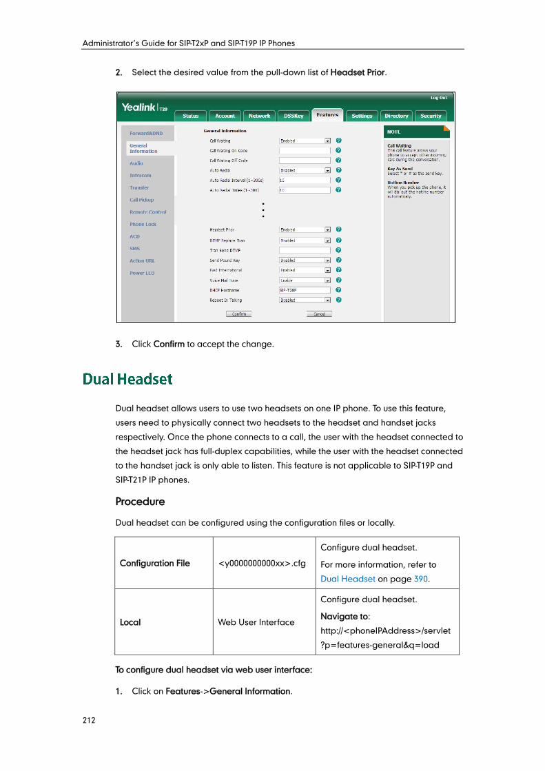
Administrator’s Guide for SIP-T2xP and SIP-T19P IP Phones
212
2. Select the desired value from the pull-down list of Headset Prior.
3. Click Confirm to accept the change.
Dual headset allows users to use two headsets on one IP phone. To use this feature,
users need to physically connect two headsets to the headset and handset jacks
respectively. Once the phone connects to a call, the user with the headset connected to
the headset jack has full-duplex capabilities, while the user with the headset connected
to the handset jack is only able to listen. This feature is not applicable to SIP-T19P and
SIP-T21P IP phones.
Procedure
Dual headset can be configured using the configuration files or locally.
Configuration File <y0000000000xx>.cfg
Configure dual headset.
For more information, refer to
Dual Headset on page 390.
Local Web User Interface
Configure dual headset.
Navigate to:
http://<phoneIPAddress>/servlet
?p=features-general&q=load
To configure dual headset via web user interface:
1. Click on Features->General Information.
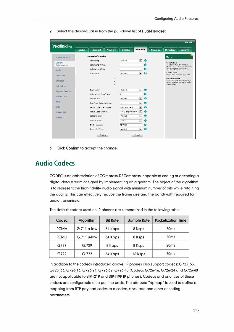
Configuring Audio Features
213
2. Select the desired value from the pull-down list of Dual-Headset.
3. Click Confirm to accept the change.
CODEC is an abbreviation of COmpress-DECompress, capable of coding or decoding a
digital data stream or signal by implementing an algorithm. The object of the algorithm
is to represent the high-fidelity audio signal with minimum number of bits while retaining
the quality. This can effectively reduce the frame size and the bandwidth required for
audio transmission.
The default codecs used on IP phones are summarized in the following table:
Codec Algorithm Bit Rate Sample Rate Packetization Time
PCMA G.711 a-law 64 Kbps 8 Ksps 20ms
PCMU G.711 u-law 64 Kbps 8 Ksps 20ms
G729 G.729 8 Kbps 8 Ksps 20ms
G722 G.722 64 Kbps 16 Ksps 20ms
In addition to the codecs introduced above, IP phones also support codecs: G723_53,
G723_63, G726-16, G726-24, G726-32, G726-40 (Codecs G726-16, G726-24 and G726-40
are not applicable to SIP-T21P and SIP-T19P IP phones). Codecs and priorities of these
codecs are configurable on a per-line basis. The attribute “rtpmap” is used to define a
mapping from RTP payload codes to a codec, clock rate and other encoding
parameters.
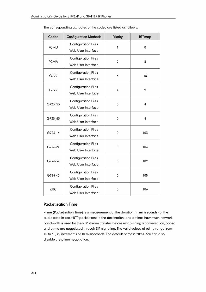
Administrator’s Guide for SIP-T2xP and SIP-T19P IP Phones
214
The corresponding attributes of the codec are listed as follows:
Codec Configuration Methods Priority RTPmap
PCMU Configuration Files
Web User Interface 1 0
PCMA Configuration Files
Web User Interface 2 8
G729 Configuration Files
Web User Interface 3 18
G722 Configuration Files
Web User Interface 4 9
G723_53 Configuration Files
Web User Interface 0 4
G723_63 Configuration Files
Web User Interface 0 4
G726-16 Configuration Files
Web User Interface 0 103
G726-24 Configuration Files
Web User Interface 0 104
G726-32 Configuration Files
Web User Interface 0 102
G726-40 Configuration Files
Web User Interface 0 105
iLBC Configuration Files
Web User Interface 0 106
Packetization Time
Ptime (Packetization Time) is a measurement of the duration (in milliseconds) of the
audio data in each RTP packet sent to the destination, and defines how much network
bandwidth is used for the RTP stream transfer. Before establishing a conversation, codec
and ptime are negotiated through SIP signaling. The valid values of ptime range from
10 to 60, in increments of 10 milliseconds. The default ptime is 20ms. You can also
disable the ptime negotiation.
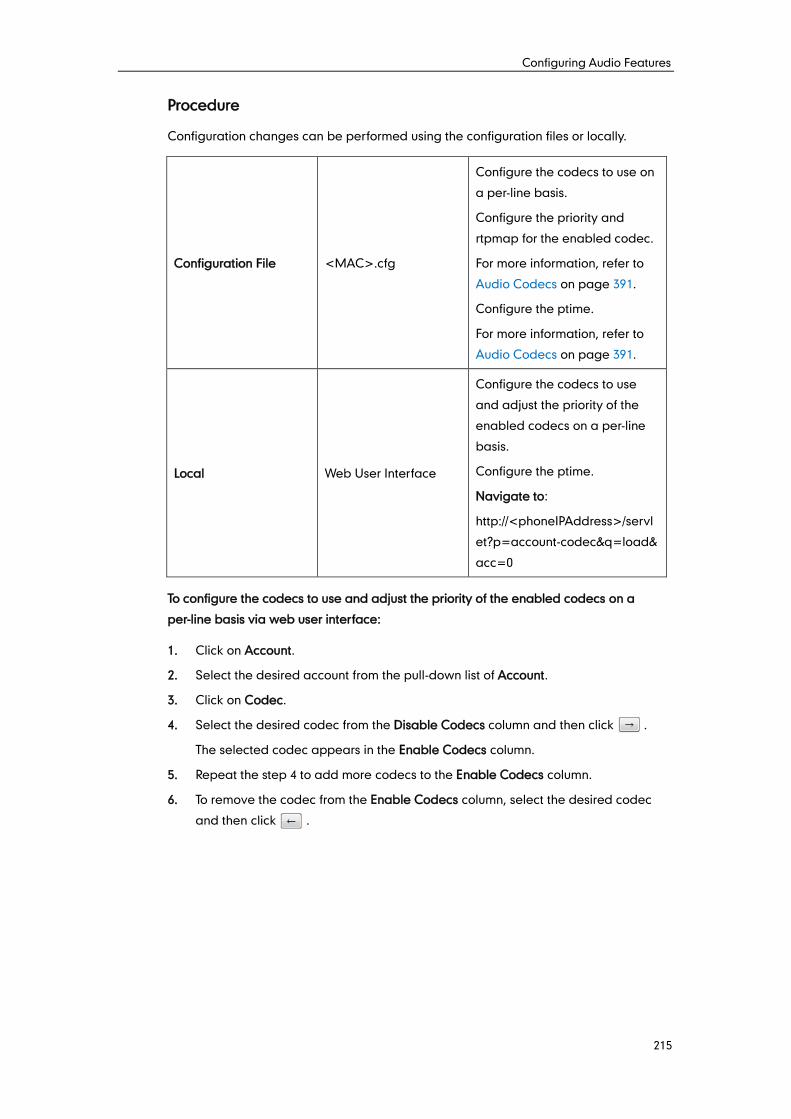
Configuring Audio Features
215
Procedure
Configuration changes can be performed using the configuration files or locally.
Configuration File <MAC>.cfg
Configure the codecs to use on
a per-line basis.
Configure the priority and
rtpmap for the enabled codec.
For more information, refer to
Audio Codecs on page 391.
Configure the ptime.
For more information, refer to
Audio Codecs on page 391.
Local Web User Interface
Configure the codecs to use
and adjust the priority of the
enabled codecs on a per-line
basis.
Configure the ptime.
Navigate to:
http://<phoneIPAddress>/servl
et?p=account-codec&q=load&
acc=0
To configure the codecs to use and adjust the priority of the enabled codecs on a
per-line basis via web user interface:
1. Click on Account.
2. Select the desired account from the pull-down list of Account.
3. Click on Codec.
4. Select the desired codec from the Disable Codecs column and then click .
The selected codec appears in the Enable Codecs column.
5. Repeat the step 4 to add more codecs to the Enable Codecs column.
6. To remove the codec from the Enable Codecs column, select the desired codec
and then click .
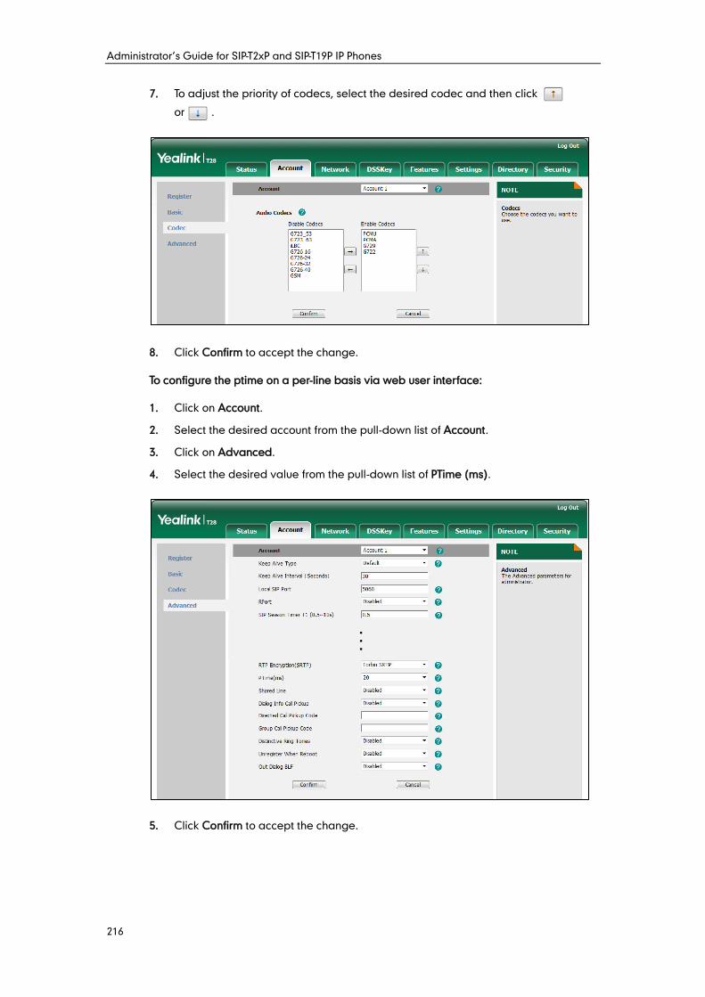
Administrator’s Guide for SIP-T2xP and SIP-T19P IP Phones
216
7. To adjust the priority of codecs, select the desired codec and then click
or .
8. Click Confirm to accept the change.
To configure the ptime on a per-line basis via web user interface:
1. Click on Account.
2. Select the desired account from the pull-down list of Account.
3. Click on Advanced.
4. Select the desired value from the pull-down list of PTime (ms).
5. Click Confirm to accept the change.
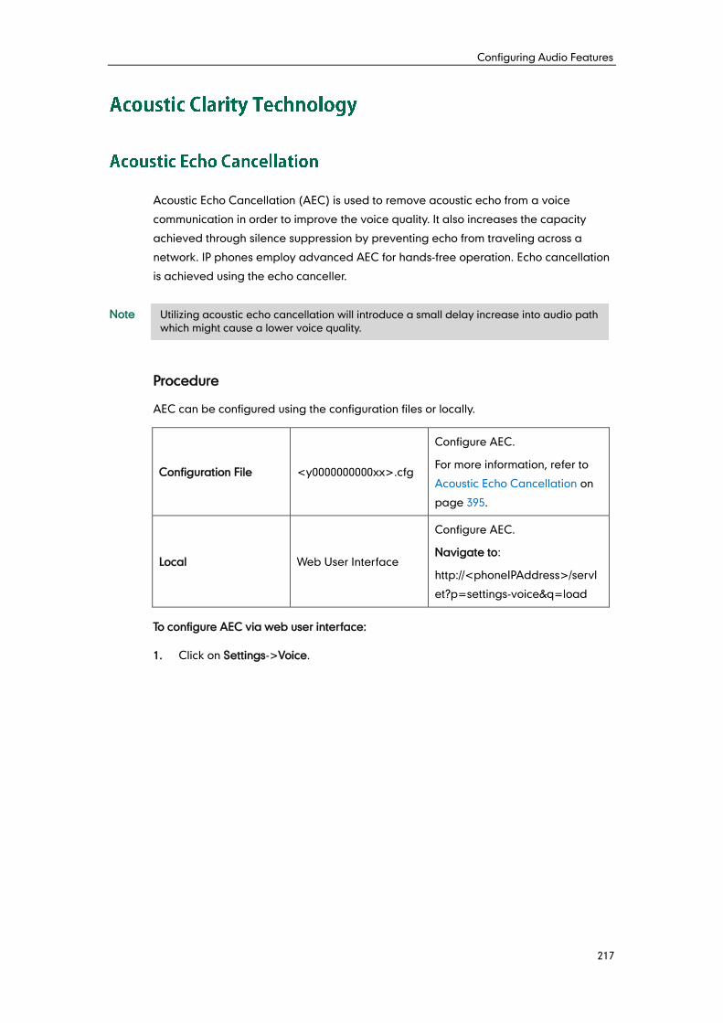
Configuring Audio Features
217
Acoustic Echo Cancellation (AEC) is used to remove acoustic echo from a voice
communication in order to improve the voice quality. It also increases the capacity
achieved through silence suppression by preventing echo from traveling across a
network. IP phones employ advanced AEC for hands-free operation. Echo cancellation
is achieved using the echo canceller.
Note
Procedure
AEC can be configured using the configuration files or locally.
Configuration File <y0000000000xx>.cfg
Configure AEC.
For more information, refer to
Acoustic Echo Cancellation on
page 395.
Local Web User Interface
Configure AEC.
Navigate to:
http://<phoneIPAddress>/servl
et?p=settings-voice&q=load
To configure AEC via web user interface:
1. Click on Settings->Voice.
Utilizing acoustic echo cancellation will introduce a small delay increase into audio path
which might cause a lower voice quality.
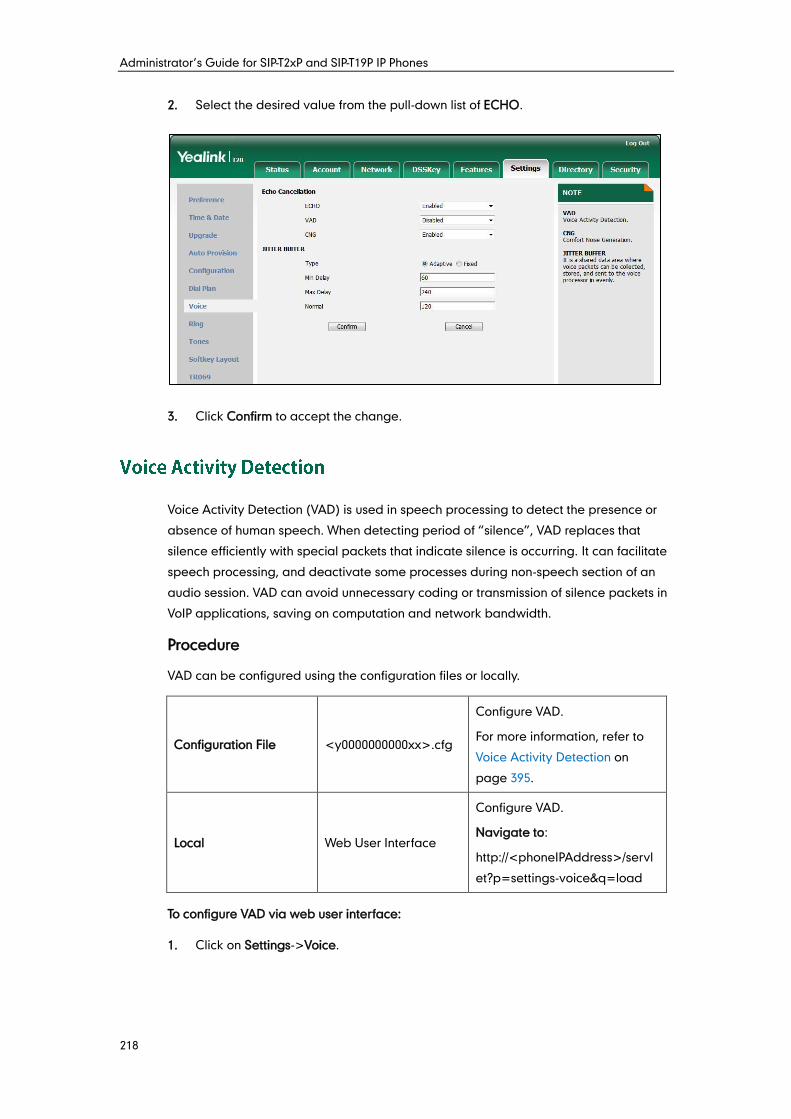
Administrator’s Guide for SIP-T2xP and SIP-T19P IP Phones
218
2. Select the desired value from the pull-down list of ECHO.
3. Click Confirm to accept the change.
Voice Activity Detection (VAD) is used in speech processing to detect the presence or
absence of human speech. When detecting period of “silence”, VAD replaces that
silence efficiently with special packets that indicate silence is occurring. It can facilitate
speech processing, and deactivate some processes during non-speech section of an
audio session. VAD can avoid unnecessary coding or transmission of silence packets in
VoIP applications, saving on computation and network bandwidth.
Procedure
VAD can be configured using the configuration files or locally.
Configuration File <y0000000000xx>.cfg
Configure VAD.
For more information, refer to
Voice Activity Detection on
page 395.
Local Web User Interface
Configure VAD.
Navigate to:
http://<phoneIPAddress>/servl
et?p=settings-voice&q=load
To configure VAD via web user interface:
1. Click on Settings->Voice.
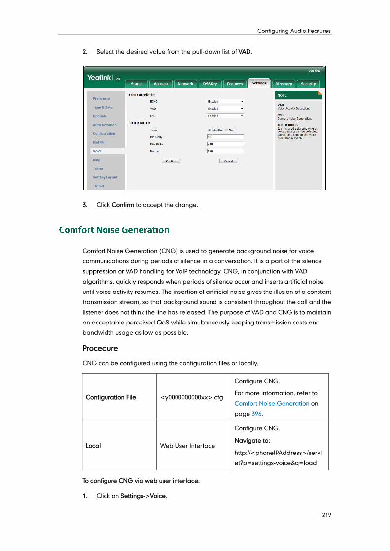
Configuring Audio Features
219
2. Select the desired value from the pull-down list of VAD.
3. Click Confirm to accept the change.
Comfort Noise Generation (CNG) is used to generate background noise for voice
communications during periods of silence in a conversation. It is a part of the silence
suppression or VAD handling for VoIP technology. CNG, in conjunction with VAD
algorithms, quickly responds when periods of silence occur and inserts artificial noise
until voice activity resumes. The insertion of artificial noise gives the illusion of a constant
transmission stream, so that background sound is consistent throughout the call and the
listener does not think the line has released. The purpose of VAD and CNG is to maintain
an acceptable perceived QoS while simultaneously keeping transmission costs and
bandwidth usage as low as possible.
Procedure
CNG can be configured using the configuration files or locally.
Configuration File <y0000000000xx>.cfg
Configure CNG.
For more information, refer to
Comfort Noise Generation on
page 396.
Local Web User Interface
Configure CNG.
Navigate to:
http://<phoneIPAddress>/servl
et?p=settings-voice&q=load
To configure CNG via web user interface:
1. Click on Settings->Voice.
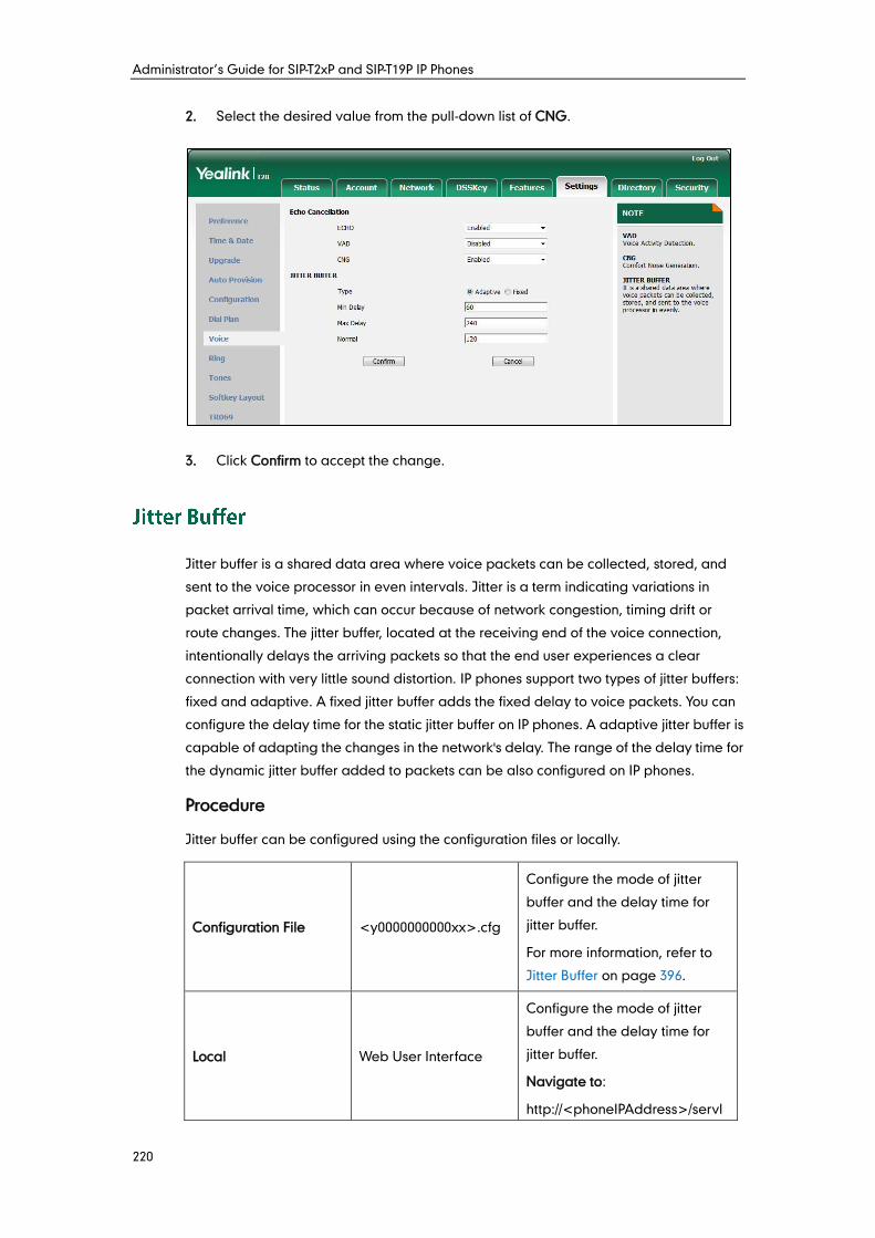
Administrator’s Guide for SIP-T2xP and SIP-T19P IP Phones
220
2. Select the desired value from the pull-down list of CNG.
3. Click Confirm to accept the change.
Jitter buffer is a shared data area where voice packets can be collected, stored, and
sent to the voice processor in even intervals. Jitter is a term indicating variations in
packet arrival time, which can occur because of network congestion, timing drift or
route changes. The jitter buffer, located at the receiving end of the voice connection,
intentionally delays the arriving packets so that the end user experiences a clear
connection with very little sound distortion. IP phones support two types of jitter buffers:
fixed and adaptive. A fixed jitter buffer adds the fixed delay to voice packets. You can
configure the delay time for the static jitter buffer on IP phones. A adaptive jitter buffer is
capable of adapting the changes in the network's delay. The range of the delay time for
the dynamic jitter buffer added to packets can be also configured on IP phones.
Procedure
Jitter buffer can be configured using the configuration files or locally.
Configuration File <y0000000000xx>.cfg
Configure the mode of jitter
buffer and the delay time for
jitter buffer.
For more information, refer to
Jitter Buffer on page 396.
Local Web User Interface
Configure the mode of jitter
buffer and the delay time for
jitter buffer.
Navigate to:
http://<phoneIPAddress>/servl
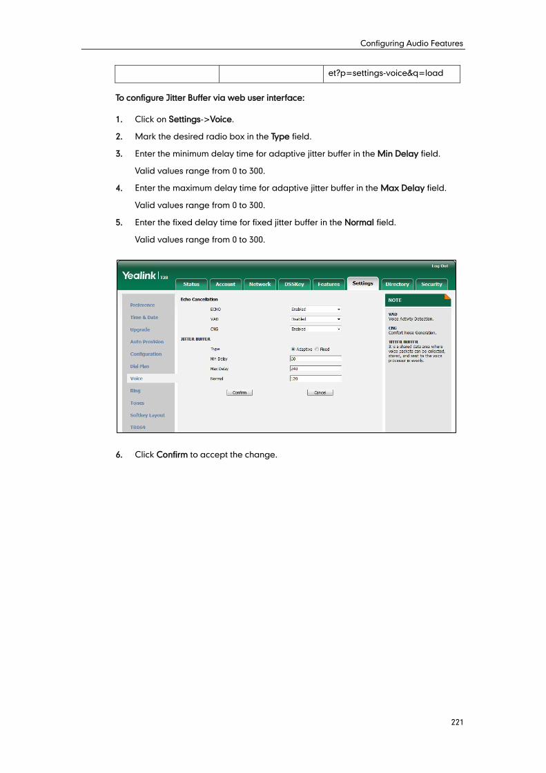
Configuring Audio Features
221
et?p=settings-voice&q=load
To configure Jitter Buffer via web user interface:
1. Click on Settings->Voice.
2. Mark the desired radio box in the Type field.
3. Enter the minimum delay time for adaptive jitter buffer in the Min Delay field.
Valid values range from 0 to 300.
4. Enter the maximum delay time for adaptive jitter buffer in the Max Delay field.
Valid values range from 0 to 300.
5. Enter the fixed delay time for fixed jitter buffer in the Normal field.
Valid values range from 0 to 300.
6. Click Confirm to accept the change.

Administrator’s Guide for SIP-T2xP and SIP-T19P IP Phones
222
Configuring Security Features
223
This chapter provides information for making configuration changes for the following
security-related features:
Transport Layer Security
Secure Real-Time Transport Protocol
Encrypting Configuration Files
TLS is a commonly-used protocol for providing communications privacy and managing
the security of message transmission, allowing IP phones to communicate with other
remote parties and connect to the HTTPS URL for provisioning in a way that is designed
to prevent eavesdropping and tampering.
TLS protocol is composed of two layers: TLS Record Protocol and TLS Handshake
Protocol. The TLS Record Protocol completes the actual data transmission and ensures
the integrity and privacy of the data. The TLS Handshake Protocol allows the server and
client to authenticate each other and negotiate an encryption algorithm and
cryptographic keys before data is exchanged.
The TLS protocol uses asymmetric encryption for authentication of key exchange,
symmetric encryption for confidentiality, and message authentication codes for
integrity.
Symmetric encryption: For symmetric encryption, the encryption key and the
corresponding decryption key can be told by each other. In most cases, the
encryption key is the same as the decryption key.
Asymmetric encryption: For asymmetric encryption, each user has a pair of
cryptographic keys – a public encryption key and a private decryption key. The
information encrypted by the public key can only be decrypted by the
corresponding private key and vice versa. Usually, the receiver keeps its private
key. The public key is known by the sender, so the sender sends the information
encrypted by the known public key, and then the receiver uses the private key to
decrypt it.
IP phones support TLS version 1.0. A cipher suite is a named combination of
authentication, encryption, and message authentication code (MAC) algorithms used
to negotiate the security settings for a network connection using the TLS/SSL network
protocol. IP phones support the following cipher suites:
DHE-RSA-AES256-SHA
DHE-DSS-AES256-SHA
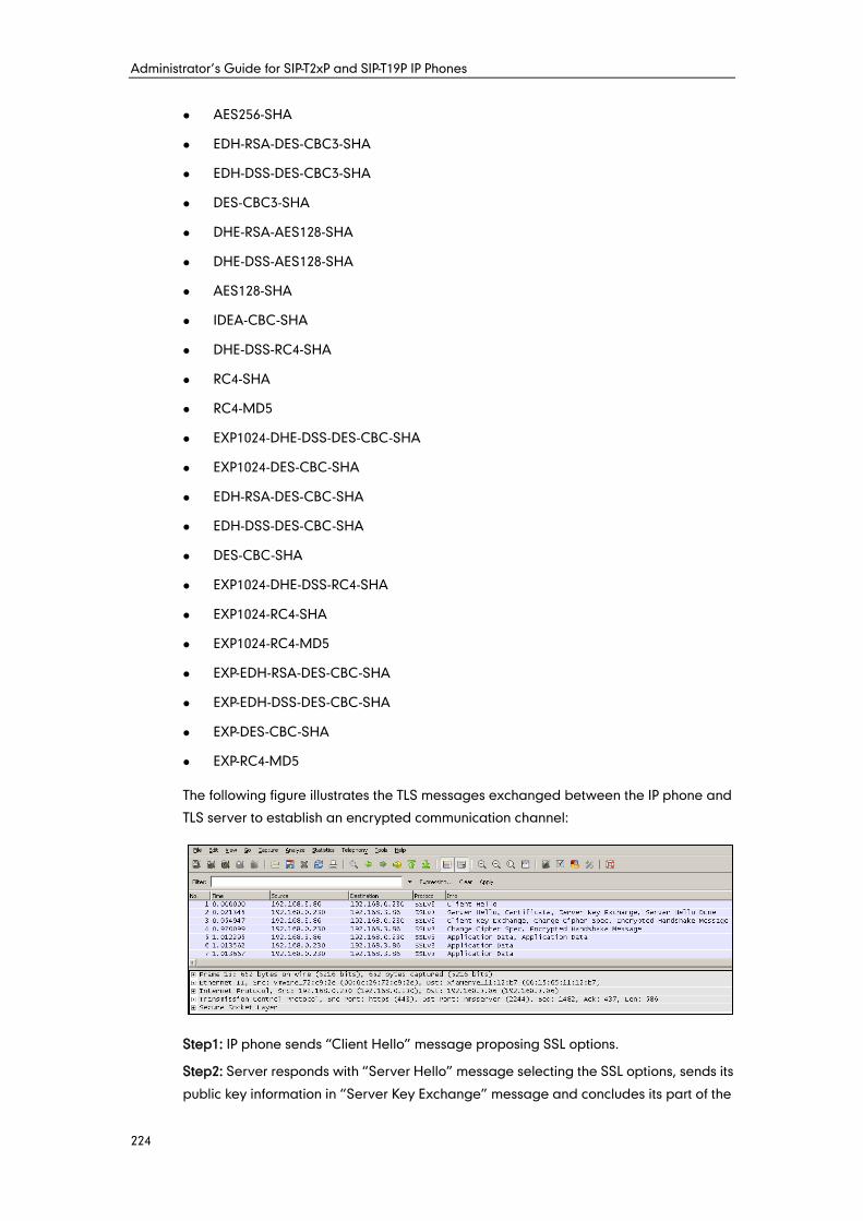
Administrator’s Guide for SIP-T2xP and SIP-T19P IP Phones
224
AES256-SHA
EDH-RSA-DES-CBC3-SHA
EDH-DSS-DES-CBC3-SHA
DES-CBC3-SHA
DHE-RSA-AES128-SHA
DHE-DSS-AES128-SHA
AES128-SHA
IDEA-CBC-SHA
DHE-DSS-RC4-SHA
RC4-SHA
RC4-MD5
EXP1024-DHE-DSS-DES-CBC-SHA
EXP1024-DES-CBC-SHA
EDH-RSA-DES-CBC-SHA
EDH-DSS-DES-CBC-SHA
DES-CBC-SHA
EXP1024-DHE-DSS-RC4-SHA
EXP1024-RC4-SHA
EXP1024-RC4-MD5
EXP-EDH-RSA-DES-CBC-SHA
EXP-EDH-DSS-DES-CBC-SHA
EXP-DES-CBC-SHA
EXP-RC4-MD5
The following figure illustrates the TLS messages exchanged between the IP phone and
TLS server to establish an encrypted communication channel:
Step1: IP phone sends “Client Hello” message proposing SSL options.
Step2: Server responds with “Server Hello” message selecting the SSL options, sends its
public key information in “Server Key Exchange” message and concludes its part of the
Configuring Security Features
225
negotiation with “Server Hello Done” message.
Step3: IP phone sends session key information (encrypted by server’s public key) in the
“Client Key Exchange” message.
Step4: Server sends “Change Cipher Spec” message to activate the negotiated options
for all future messages it will send.
IP phones can encrypt SIP with TLS, which is called SIPS. When TLS is enabled for an
account, the SIP message of this account will be encrypted, and a lock icon appears on
the LCD screen after the successful TLS negotiation.
Certificates
The IP phone can serve as a TLS client or a TLS server. The TLS requires the following
security certificates to perform the TLS handshake:
Trusted Certificate: When the IP phone requests a TLS connection with a server, the
IP phone should verify the certificate sent by the server to decide whether it is
trusted based on the trusted certificates list. The IP phone has 30 built-in trusted
certificates. You can upload 10 custom certificates at most. The format of the trusted
certificate files must be *.pem,*.cer,*.crt and *.der and the maximum file size is
5MB. For more information on 30 trusted certificates, refer to Appendix C: Trusted
Certificates on page 268.
Server Certificate: When clients request a TLS connection with the IP phone, the IP
phone sends the server certificate to the clients for authentication. The IP phone
has two types of built-in server certificates: a unique server certificate and a
generic server certificate. You can only upload one server certificate to the IP
phone. The old server certificate will be overridden by the new one. The format of
the server certificate files must be *.pem and *.cer and the maximum file size is
5MB.
- A unique server certificate: It is unique to an IP phone (based on the MAC
address) and issued by the Yealink Certificate Authority (CA).
- A generic server certificate: It issued by the Yealink Certificate Authority (CA).
Only if no unique certificate exists, the IP phone may send a generic certificate
for authentication.
The IP phone can authenticate the server certificate based on the trusted certificates list.
The trusted certificates list and the server certificates list contain the default and custom
certificates. You can specify the type of certificates the IP phone accepts: default
certificates, custom certificates or all certificates.
Administrator’s Guide for SIP-T2xP and SIP-T19P IP Phones
226
Common Name Validation feature enables the IP phone to mandatorily validate the
common name of the certificate sent by the connecting server.
Note
Procedure
Configuration changes can be performed using the configuration files or locally.
Configuration File
<MAC>.cfg
Configure TLS on a per-line
basis.
For more information, refer to
TLS on page 398.
<y0000000000xx>.cfg
Configure trusted certificates
feature.
Configure server certificates
feature.
For more information, refer to
TLS on page 398.
Upload the trusted certificates.
Upload the server certificates.
For more information, refer to
Uploading Certificates on page
400.
Local Web User Interface
Configure TLS on a per-line
basis.
Navigate to:
http://<phoneIPAddress>/servl
et?p=account-register&q=load
&acc=0
Configure trusted certificates
feature.
In TLS feature, we use the terms trusted and server certificate. These are also known as
CA and device certificates.
Firmware upgrade from version 71 to 72 will result in update of the generic server
certificates.
We strongly recommend that you do not downgrade the firmware. For
SIP-T20P/T22P/T26P/T28P IP phones, firmware downgrade will result in damage to the
unique server certificate.
Resetting the IP phone to factory defaults will delete custom certificates by default. But
this feature is configurable using the configuration files. For more information on the
configuration parameter, refer to TLS on page 398.
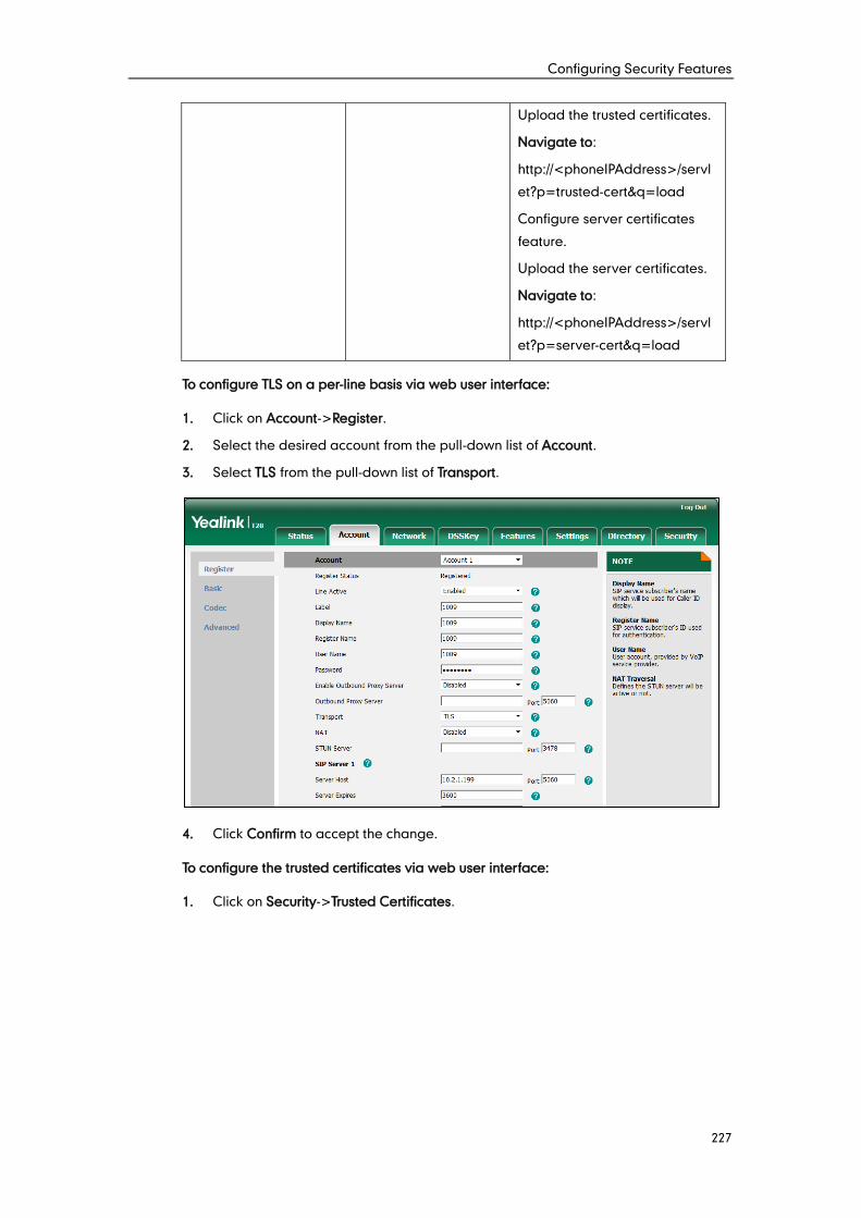
Configuring Security Features
227
Upload the trusted certificates.
Navigate to:
http://<phoneIPAddress>/servl
et?p=trusted-cert&q=load
Configure server certificates
feature.
Upload the server certificates.
Navigate to:
http://<phoneIPAddress>/servl
et?p=server-cert&q=load
To configure TLS on a per-line basis via web user interface:
1. Click on Account->Register.
2. Select the desired account from the pull-down list of Account.
3. Select TLS from the pull-down list of Transport.
4. Click Confirm to accept the change.
To configure the trusted certificates via web user interface:
1. Click on Security->Trusted Certificates.
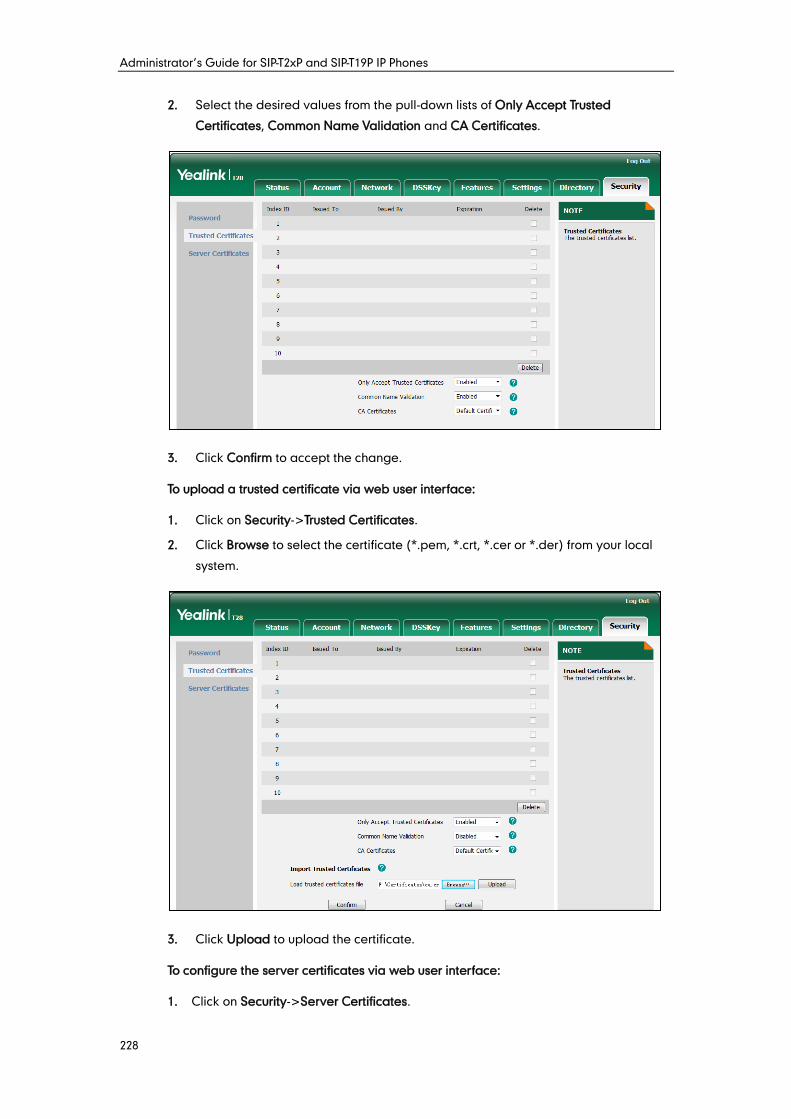
Administrator’s Guide for SIP-T2xP and SIP-T19P IP Phones
228
2. Select the desired values from the pull-down lists of Only Accept Trusted
Certificates, Common Name Validation and CA Certificates.
3. Click Confirm to accept the change.
To upload a trusted certificate via web user interface:
1. Click on Security->Trusted Certificates.
2. Click Browse to select the certificate (*.pem, *.crt, *.cer or *.der) from your local
system.
3. Click Upload to upload the certificate.
To configure the server certificates via web user interface:
1. Click on Security->Server Certificates.
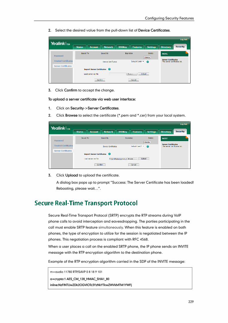
Configuring Security Features
229
2. Select the desired value from the pull-down list of Device Certificates.
3. Click Confirm to accept the change.
To upload a server certificate via web user interface:
1. Click on Security->Server Certificates.
2. Click Browse to select the certificate (*.pem and *.cer) from your local system.
3. Click Upload to upload the certificate.
A dialog box pops up to prompt “Success: The Server Certificate has been loaded!
Rebooting, please wait…”.
Secure Real-Time Transport Protocol (SRTP) encrypts the RTP streams during VoIP
phone calls to avoid interception and eavesdropping. The parties participating in the
call must enable SRTP feature simultaneously. When this feature is enabled on both
phones, the type of encryption to utilize for the session is negotiated between the IP
phones. This negotiation process is compliant with RFC 4568.
When a user places a call on the enabled SRTP phone, the IP phone sends an INVITE
message with the RTP encryption algorithm to the destination phone.
Example of the RTP encryption algorithm carried in the SDP of the INVITE message:
m=audio 11780 RTP/SAVP 0 8 18 9 101
a=crypto:1 AES_CM_128_HMAC_SHA1_80
inline:NzFlNTUwZDk2OGVlOTc3YzNkYTkwZWVkMTM1YWFj
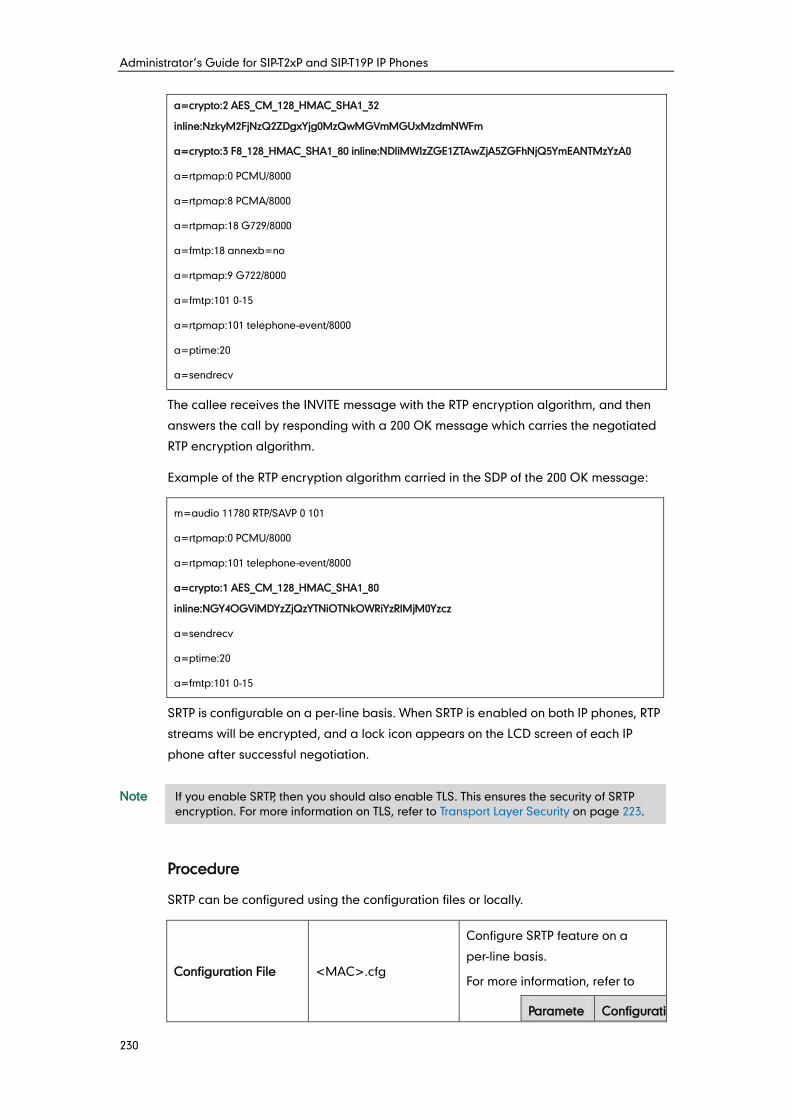
Administrator’s Guide for SIP-T2xP and SIP-T19P IP Phones
230
a=crypto:2 AES_CM_128_HMAC_SHA1_32
inline:NzkyM2FjNzQ2ZDgxYjg0MzQwMGVmMGUxMzdmNWFm
a=crypto:3 F8_128_HMAC_SHA1_80 inline:NDliMWIzZGE1ZTAwZjA5ZGFhNjQ5YmEANTMzYzA0
a=rtpmap:0 PCMU/8000
a=rtpmap:8 PCMA/8000
a=rtpmap:18 G729/8000
a=fmtp:18 annexb=no
a=rtpmap:9 G722/8000
a=fmtp:101 0-15
a=rtpmap:101 telephone-event/8000
a=ptime:20
a=sendrecv
The callee receives the INVITE message with the RTP encryption algorithm, and then
answers the call by responding with a 200 OK message which carries the negotiated
RTP encryption algorithm.
Example of the RTP encryption algorithm carried in the SDP of the 200 OK message:
m=audio 11780 RTP/SAVP 0 101
a=rtpmap:0 PCMU/8000
a=rtpmap:101 telephone-event/8000
a=crypto:1 AES_CM_128_HMAC_SHA1_80
inline:NGY4OGViMDYzZjQzYTNiOTNkOWRiYzRlMjM0Yzcz
a=sendrecv
a=ptime:20
a=fmtp:101 0-15
SRTP is configurable on a per-line basis. When SRTP is enabled on both IP phones, RTP
streams will be encrypted, and a lock icon appears on the LCD screen of each IP
phone after successful negotiation.
Note
Procedure
SRTP can be configured using the configuration files or locally.
Configuration File <MAC>.cfg
Configure SRTP feature on a
per-line basis.
For more information, refer to
Paramete Configuratio
If you enable SRTP, then you should also enable TLS. This ensures the security of SRTP
encryption. For more information on TLS, refer to Transport Layer Security on page 223.
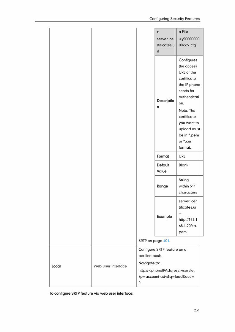
Configuring Security Features
231
r-
server_ce
rtificates.u
rl
n File
<y00000000
00xx>.cfg
Descriptio
n
Configures
the access
URL of the
certificate
the IP phone
sends for
authenticati
on.
Note: The
certificate
you want to
upload must
be in *.pem
or *.cer
format.
Format URL
Default
Value
Blank
Range
String
within 511
characters
Example
server_cer
tificates.url
=
http://192.1
68.1.20/ca.
pem
SRTP on page 401.
Local Web User Interface
Configure SRTP feature on a
per-line basis.
Navigate to:
http://<phoneIPAddress>/servlet
?p=account-adv&q=load&acc=
0
To configure SRTP feature via web user interface:
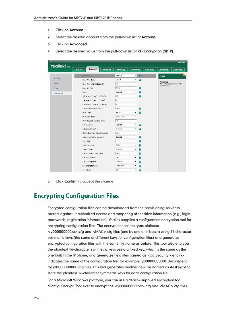
Administrator’s Guide for SIP-T2xP and SIP-T19P IP Phones
232
1. Click on Account.
2. Select the desired account from the pull-down list of Account.
3. Click on Advanced.
4. Select the desired value from the pull-down list of RTP Encryption (SRTP).
5. Click Confirm to accept the change.
Encrypted configuration files can be downloaded from the provisioning server to
protect against unauthorized access and tampering of sensitive information (e.g., login
passwords, registration information). Yealink supplies a configuration encryption tool for
encrypting configuration files. The encryption tool encrypts plaintext
<y0000000000xx>.cfg and <MAC>.cfg files (one by one or in batch) using 16-character
symmetric keys (the same or different keys for configuration files) and generates
encrypted configuration files with the same file name as before. This tool also encrypts
the plaintext 16-character symmetric keys using a fixed key, which is the same as the
one built in the IP phone, and generates new files named as <xx_Security>.enc (xx
indicates the name of the configuration file, for example, y000000000000_Security.enc
for y000000000000.cfg file). This tool generates another new file named as Aeskey.txt to
store the plaintext 16-character symmetric keys for each configuration file.
For a Microsoft Windows platform, you can use a Yealink-supplied encryption tool
"Config_Encrypt_Tool.exe" to encrypt the <y0000000000xx>.cfg and <MAC>.cfg files
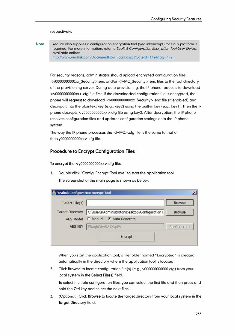
Configuring Security Features
233
respectively.
Note
For security reasons, administrator should upload encrypted configuration files,
<y0000000000xx_Security>.enc and/or <MAC_Security>.enc files to the root directory
of the provisioning server. During auto provisioning, the IP phone requests to download
<y0000000000xx>.cfg file first. If the downloaded configuration file is encrypted, the
phone will request to download <y0000000000xx_Security>.enc file (if enabled) and
decrypt it into the plaintext key (e.g., key2) using the built-in key (e.g., key1). Then the IP
phone decrypts <y0000000000xx>.cfg file using key2. After decryption, the IP phone
resolves configuration files and updates configuration settings onto the IP phone
system.
The way the IP phone processes the <MAC>.cfg file is the same to that of
the<y0000000000xx>.cfg file.
Procedure to Encrypt Configuration Files
To encrypt the <y0000000000xx>.cfg file:
1. Double click “Config_Encrypt_Tool.exe” to start the application tool.
The screenshot of the main page is shown as below:
When you start the application tool, a file folder named “Encrypted” is created
automatically in the directory where the application tool is located.
2. Click Browse to locate configuration file(s) (e.g., y000000000000.cfg) from your
local system in the Select File(s) field.
To select multiple configuration files, you can select the first file and then press and
hold the Ctrl key and select the next files.
3. (Optional.) Click Browse to locate the target directory from your local system in the
Target Directory field.
Yealink also supplies a configuration encryption tool (yealinkencrypt) for Linux platform if
required. For more information, refer to Yealink Configuration Encryption Tool User Guide,
available online:
http://www.yealink.com/DocumentDownload.aspx?CateId=142&flag=142.
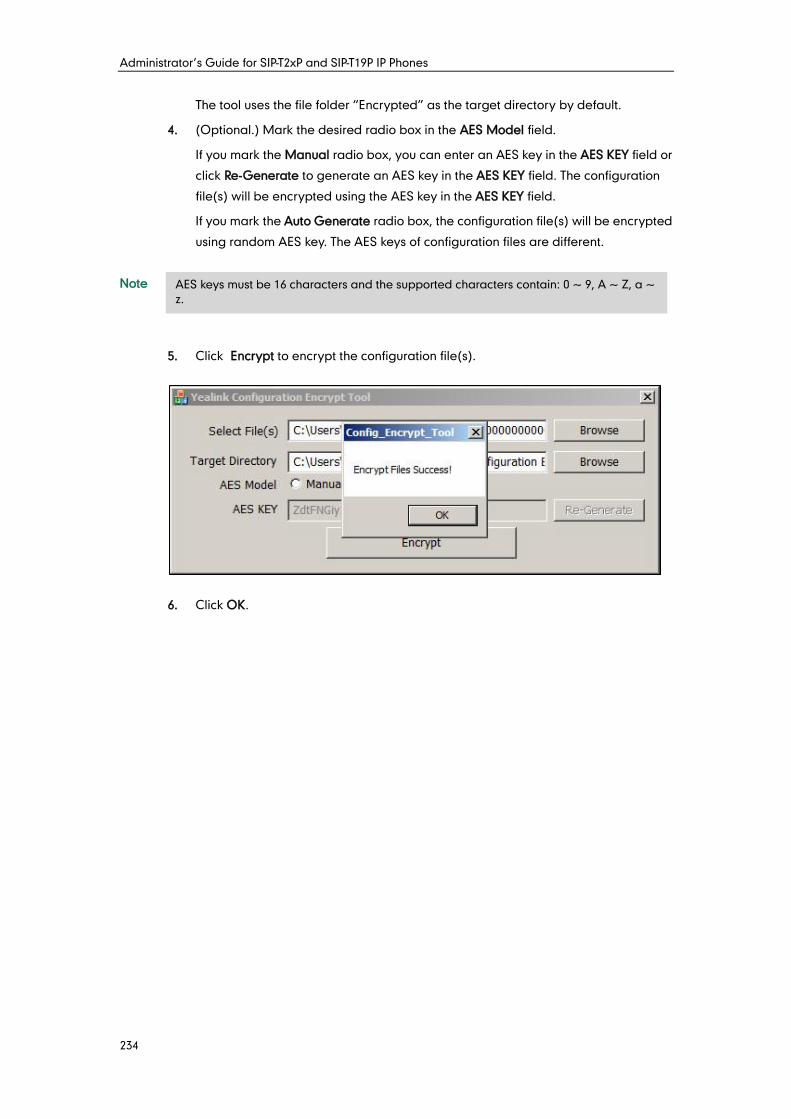
Administrator’s Guide for SIP-T2xP and SIP-T19P IP Phones
234
The tool uses the file folder “Encrypted” as the target directory by default.
4. (Optional.) Mark the desired radio box in the AES Model field.
If you mark the Manual radio box, you can enter an AES key in the AES KEY field or
click Re-Generate to generate an AES key in the AES KEY field. The configuration
file(s) will be encrypted using the AES key in the AES KEY field.
If you mark the Auto Generate radio box, the configuration file(s) will be encrypted
using random AES key. The AES keys of configuration files are different.
Note
5. Click Encrypt to encrypt the configuration file(s).
6. Click OK.
AES keys must be 16 characters and the supported characters contain: 0 ~ 9, A ~ Z, a ~
z.
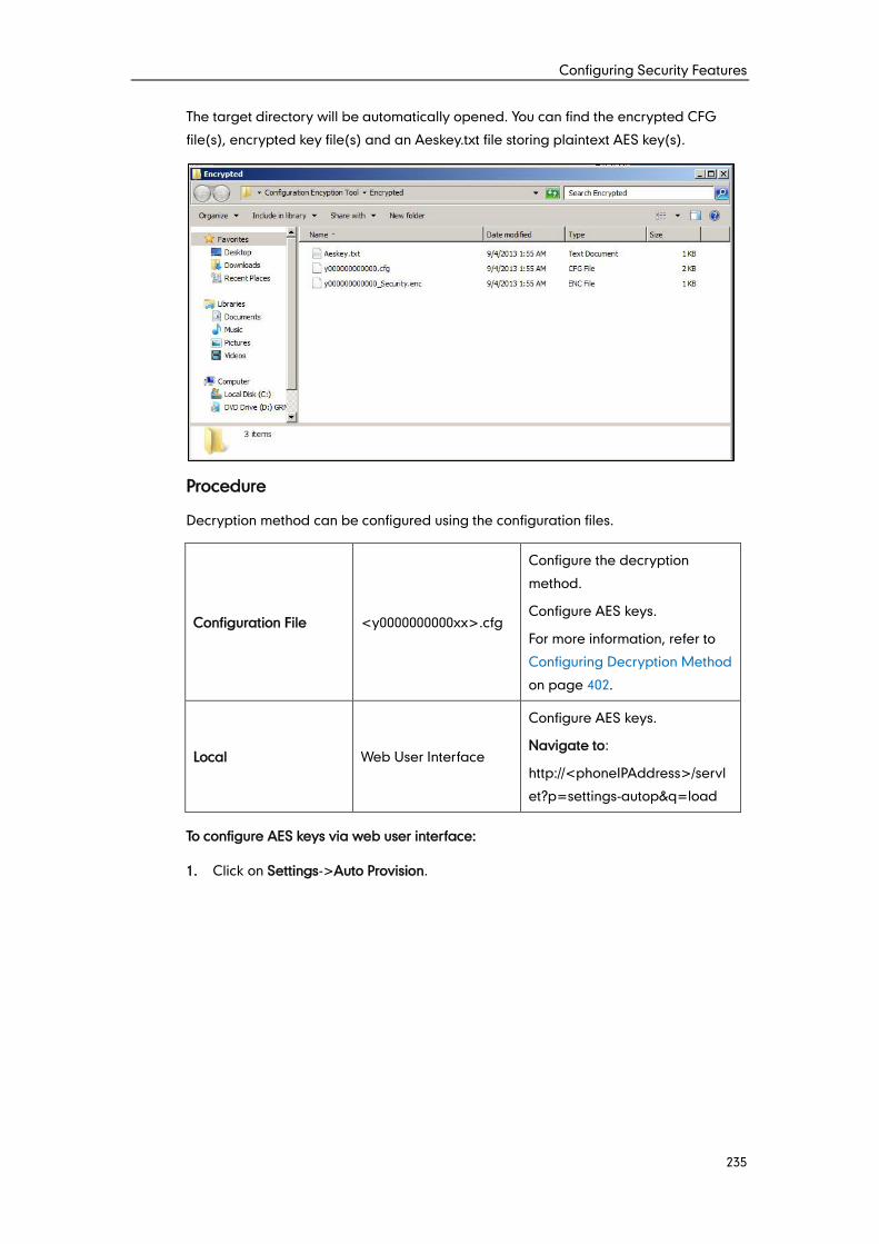
Configuring Security Features
235
The target directory will be automatically opened. You can find the encrypted CFG
file(s), encrypted key file(s) and an Aeskey.txt file storing plaintext AES key(s).
Procedure
Decryption method can be configured using the configuration files.
Configuration File <y0000000000xx>.cfg
Configure the decryption
method.
Configure AES keys.
For more information, refer to
Configuring Decryption Method
on page 402.
Local Web User Interface
Configure AES keys.
Navigate to:
http://<phoneIPAddress>/servl
et?p=settings-autop&q=load
To configure AES keys via web user interface:
1. Click on Settings->Auto Provision.
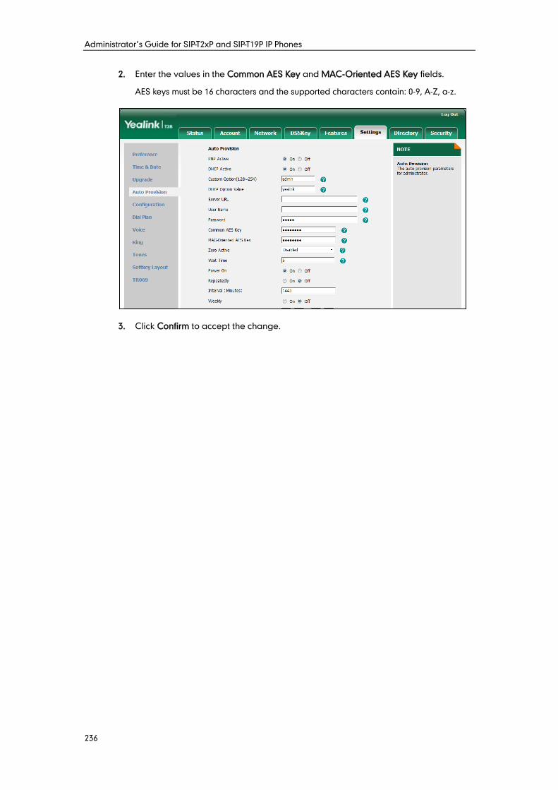
Administrator’s Guide for SIP-T2xP and SIP-T19P IP Phones
236
2. Enter the values in the Common AES Key and MAC-Oriented AES Key fields.
AES keys must be 16 characters and the supported characters contain: 0-9, A-Z, a-z.
3. Click Confirm to accept the change.

Configuring Security Features
237
Administrator’s Guide for SIP-T2xP and SIP-T19P IP Phones
238
When configuring particular features, you may need to upload resource files (e.g., local
contact directory, remote phone book) to IP phones. The resources files can be local
contact directory, remote phone book and so on. Ask Yealink field application engineer
for resource file templates. If the resource file is to be used for all IP phones of the same
model, the resource file access URL is best specified in the <y0000000000xx>.cfg file.
However, if you want to specify the desired phone to use the resource file, the resource
file access URL should be specified in the <MAC>.cfg file.
This chapter provides the detailed information on how to customize the following
resource files and specify the access URL:
Replace Rule Template
Dial-now Template
Softkey Layout Template
Directory Template
Super Search Template
Local Contact File
Remote XML Phone Book
Specifying the Access URL of Resource Files
The replace rule template helps with the creation of multiple replace rules. After setup,
place the replace rule template to the provisioning server and specify the access URL in
the configuration files.
When editing a replace rule template, learn the following:
<DialRule> indicates the start of a template and </DialRule> indicates the end of
a template.
Create replace rules between <DialRule> and </DialRule>.
When specifying the desired line(s) to apply the replace rule, the valid values are 0
and line ID. The digit 0 stands for all lines. Multiple line IDs are separated by
commas. This is not applicable to SIP-T19P IP phones.
At most 100 replace rules can be added to the IP phone.
The expression syntax in the replace rule template is the same as that introduced
in the section Dial Plan on page 67.
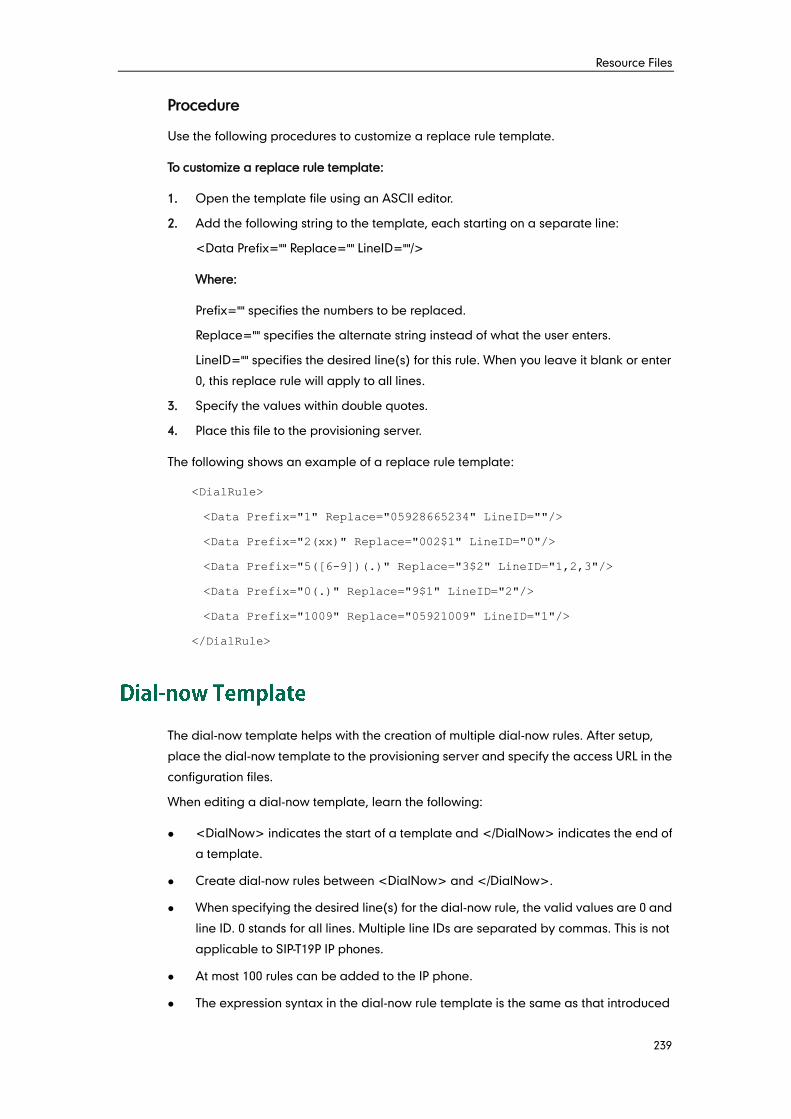
Resource Files
239
Procedure
Use the following procedures to customize a replace rule template.
To customize a replace rule template:
1. Open the template file using an ASCII editor.
2. Add the following string to the template, each starting on a separate line:
<Data Prefix="" Replace="" LineID=""/>
Where:
Prefix="" specifies the numbers to be replaced.
Replace="" specifies the alternate string instead of what the user enters.
LineID="" specifies the desired line(s) for this rule. When you leave it blank or enter
0, this replace rule will apply to all lines.
3. Specify the values within double quotes.
4. Place this file to the provisioning server.
The following shows an example of a replace rule template:
<DialRule>
<Data Prefix="1" Replace="05928665234" LineID=""/>
<Data Prefix="2(xx)" Replace="002$1" LineID="0"/>
<Data Prefix="5([6-9])(.)" Replace="3$2" LineID="1,2,3"/>
<Data Prefix="0(.)" Replace="9$1" LineID="2"/>
<Data Prefix="1009" Replace="05921009" LineID="1"/>
</DialRule>
The dial-now template helps with the creation of multiple dial-now rules. After setup,
place the dial-now template to the provisioning server and specify the access URL in the
configuration files.
When editing a dial-now template, learn the following:
<DialNow> indicates the start of a template and </DialNow> indicates the end of
a template.
Create dial-now rules between <DialNow> and </DialNow>.
When specifying the desired line(s) for the dial-now rule, the valid values are 0 and
line ID. 0 stands for all lines. Multiple line IDs are separated by commas. This is not
applicable to SIP-T19P IP phones.
At most 100 rules can be added to the IP phone.
The expression syntax in the dial-now rule template is the same as that introduced
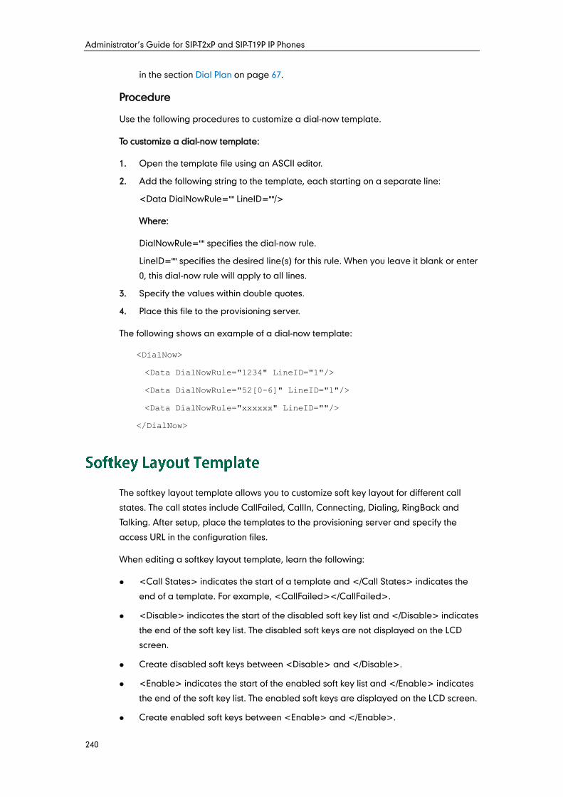
Administrator’s Guide for SIP-T2xP and SIP-T19P IP Phones
240
in the section Dial Plan on page 67.
Procedure
Use the following procedures to customize a dial-now template.
To customize a dial-now template:
1. Open the template file using an ASCII editor.
2. Add the following string to the template, each starting on a separate line:
<Data DialNowRule="" LineID=""/>
Where:
DialNowRule="" specifies the dial-now rule.
LineID="" specifies the desired line(s) for this rule. When you leave it blank or enter
0, this dial-now rule will apply to all lines.
3. Specify the values within double quotes.
4. Place this file to the provisioning server.
The following shows an example of a dial-now template:
<DialNow>
<Data DialNowRule="1234" LineID="1"/>
<Data DialNowRule="52[0-6]" LineID="1"/>
<Data DialNowRule="xxxxxx" LineID=""/>
</DialNow>
The softkey layout template allows you to customize soft key layout for different call
states. The call states include CallFailed, CallIn, Connecting, Dialing, RingBack and
Talking. After setup, place the templates to the provisioning server and specify the
access URL in the configuration files.
When editing a softkey layout template, learn the following:
<Call States> indicates the start of a template and </Call States> indicates the
end of a template. For example, <CallFailed></CallFailed>.
<Disable> indicates the start of the disabled soft key list and </Disable> indicates
the end of the soft key list. The disabled soft keys are not displayed on the LCD
screen.
Create disabled soft keys between <Disable> and </Disable>.
<Enable> indicates the start of the enabled soft key list and </Enable> indicates
the end of the soft key list. The enabled soft keys are displayed on the LCD screen.
Create enabled soft keys between <Enable> and </Enable>.
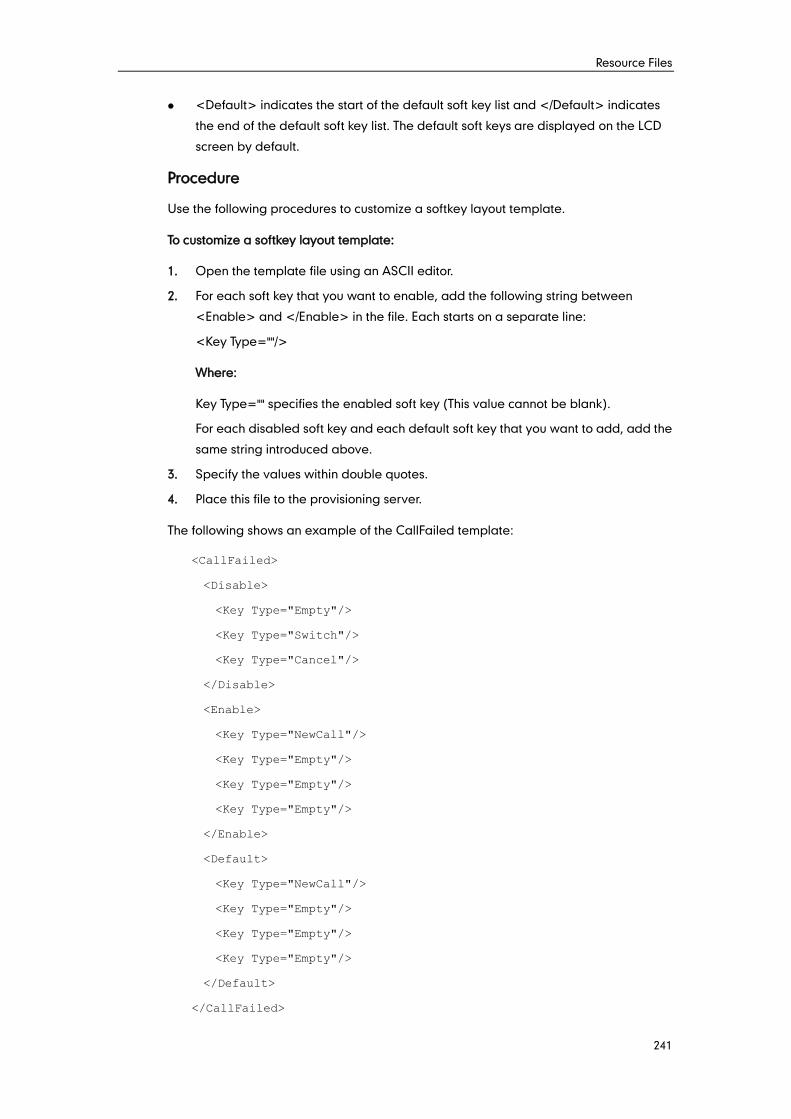
Resource Files
241
<Default> indicates the start of the default soft key list and </Default> indicates
the end of the default soft key list. The default soft keys are displayed on the LCD
screen by default.
Procedure
Use the following procedures to customize a softkey layout template.
To customize a softkey layout template:
1. Open the template file using an ASCII editor.
2. For each soft key that you want to enable, add the following string between
<Enable> and </Enable> in the file. Each starts on a separate line:
<Key Type=""/>
Where:
Key Type="" specifies the enabled soft key (This value cannot be blank).
For each disabled soft key and each default soft key that you want to add, add the
same string introduced above.
3. Specify the values within double quotes.
4. Place this file to the provisioning server.
The following shows an example of the CallFailed template:
<CallFailed>
<Disable>
<Key Type="Empty"/>
<Key Type="Switch"/>
<Key Type="Cancel"/>
</Disable>
<Enable>
<Key Type="NewCall"/>
<Key Type="Empty"/>
<Key Type="Empty"/>
<Key Type="Empty"/>
</Enable>
<Default>
<Key Type="NewCall"/>
<Key Type="Empty"/>
<Key Type="Empty"/>
<Key Type="Empty"/>
</Default>
</CallFailed>
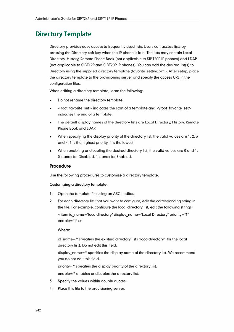
Administrator’s Guide for SIP-T2xP and SIP-T19P IP Phones
242
Directory provides easy access to frequently used lists. Users can access lists by
pressing the Directory soft key when the IP phone is idle. The lists may contain Local
Directory, History, Remote Phone Book (not applicable to SIP-T20P IP phones) and LDAP
(not applicable to SIP-T19P and SIP-T20P IP phones). You can add the desired list(s) to
Directory using the supplied directory template (favorite_setting.xml). After setup, place
the directory template to the provisioning server and specify the access URL in the
configuration files.
When editing a directory template, learn the following:
Do not rename the directory template.
<root_favorite_set> indicates the start of a template and </root_favorite_set>
indicates the end of a template.
The default display names of the directory lists are Local Directory, History, Remote
Phone Book and LDAP.
When specifying the display priority of the directory list, the valid values are 1, 2, 3
and 4. 1 is the highest priority, 4 is the lowest.
When enabling or disabling the desired directory list, the valid values are 0 and 1.
0 stands for Disabled, 1 stands for Enabled.
Procedure
Use the following procedures to customize a directory template.
Customizing a directory template:
1. Open the template file using an ASCII editor.
2. For each directory list that you want to configure, edit the corresponding string in
the file. For example, configure the local directory list, edit the following strings:
<item id_name="localdirectory" display_name="Local Directory" priority="1"
enable="1" />
Where:
id_name="" specifies the existing directory list (“localdirectory” for the local
directory list). Do not edit this field.
display_name="" specifies the display name of the directory list. We recommend
you do not edit this field.
priority="" specifies the display priority of the directory list.
enable="" enables or disables the directory list.
3. Specify the values within double quotes.
4. Place this file to the provisioning server.
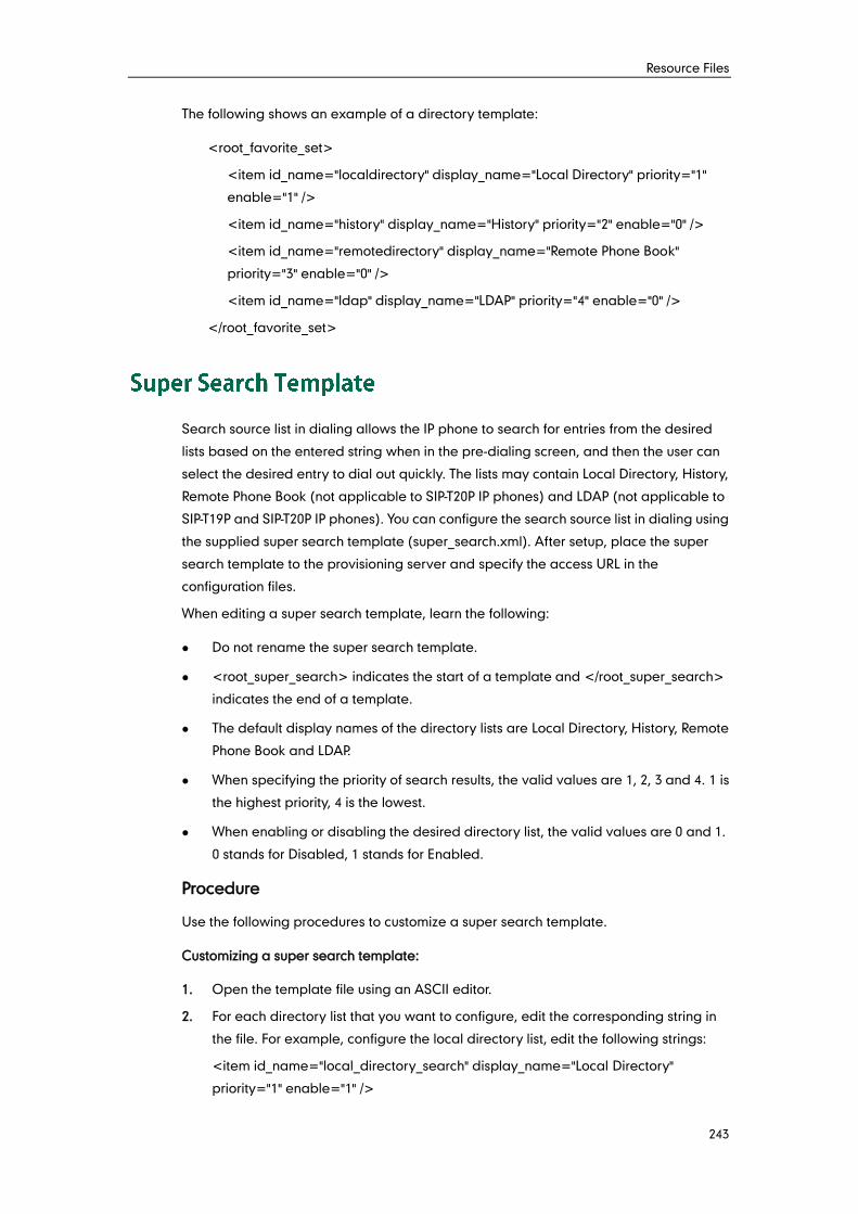
Resource Files
243
The following shows an example of a directory template:
<root_favorite_set>
<item id_name="localdirectory" display_name="Local Directory" priority="1"
enable="1" />
<item id_name="history" display_name="History" priority="2" enable="0" />
<item id_name="remotedirectory" display_name="Remote Phone Book"
priority="3" enable="0" />
<item id_name="ldap" display_name="LDAP" priority="4" enable="0" />
</root_favorite_set>
Search source list in dialing allows the IP phone to search for entries from the desired
lists based on the entered string when in the pre-dialing screen, and then the user can
select the desired entry to dial out quickly. The lists may contain Local Directory, History,
Remote Phone Book (not applicable to SIP-T20P IP phones) and LDAP (not applicable to
SIP-T19P and SIP-T20P IP phones). You can configure the search source list in dialing using
the supplied super search template (super_search.xml). After setup, place the super
search template to the provisioning server and specify the access URL in the
configuration files.
When editing a super search template, learn the following:
Do not rename the super search template.
<root_super_search> indicates the start of a template and </root_super_search>
indicates the end of a template.
The default display names of the directory lists are Local Directory, History, Remote
Phone Book and LDAP.
When specifying the priority of search results, the valid values are 1, 2, 3 and 4. 1 is
the highest priority, 4 is the lowest.
When enabling or disabling the desired directory list, the valid values are 0 and 1.
0 stands for Disabled, 1 stands for Enabled.
Procedure
Use the following procedures to customize a super search template.
Customizing a super search template:
1. Open the template file using an ASCII editor.
2. For each directory list that you want to configure, edit the corresponding string in
the file. For example, configure the local directory list, edit the following strings:
<item id_name="local_directory_search" display_name="Local Directory"
priority="1" enable="1" />
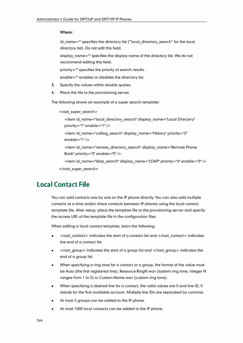
Administrator’s Guide for SIP-T2xP and SIP-T19P IP Phones
244
Where:
id_name="" specifies the directory list (“local_directory_search” for the local
directory list). Do not edit this field.
display_name="" specifies the display name of the directory list. We do not
recommend editing this field.
priority="" specifies the priority of search results.
enable="" enables or disables the directory list.
3. Specify the values within double quotes.
4. Place this file to the provisioning server.
The following shows an example of a super search template:
<root_super_search>
<item id_name="local_directory_search" display_name="Local Directory"
priority="1" enable="1" />
<item id_name="calllog_search" display_name="History" priority="2"
enable="1" />
<item id_name="remote_directory_search" display_name="Remote Phone
Book" priority="3" enable="0" />
<item id_name="ldap_search" display_name="LDAP" priority="4" enable="0" />
</root_super_search>
You can add contacts one by one on the IP phone directly. You can also add multiple
contacts at a time and/or share contacts between IP phones using the local contact
template file. After setup, place the template file to the provisioning server and specify
the access URL of the template file in the configuration files.
When editing a local contact template, learn the following:
<root_contact> indicates the start of a contact list and </root_contact> indicates
the end of a contact list.
<root_group> indicates the start of a group list and </root_group> indicates the
end of a group list.
When specifying a ring tone for a contact or a group, the format of the value must
be Auto (the first registered line), Resource:RingN.wav (system ring tone, integer N
ranges from 1 to 5) or Custom:Name.wav (custom ring tone).
When specifying a desired line for a contact, the valid values are 0 and line ID, 0
stands for the first available account. Multiple line IDs are separated by commas.
At most 5 groups can be added to the IP phone.
At most 1000 local contacts can be added to the IP phone.
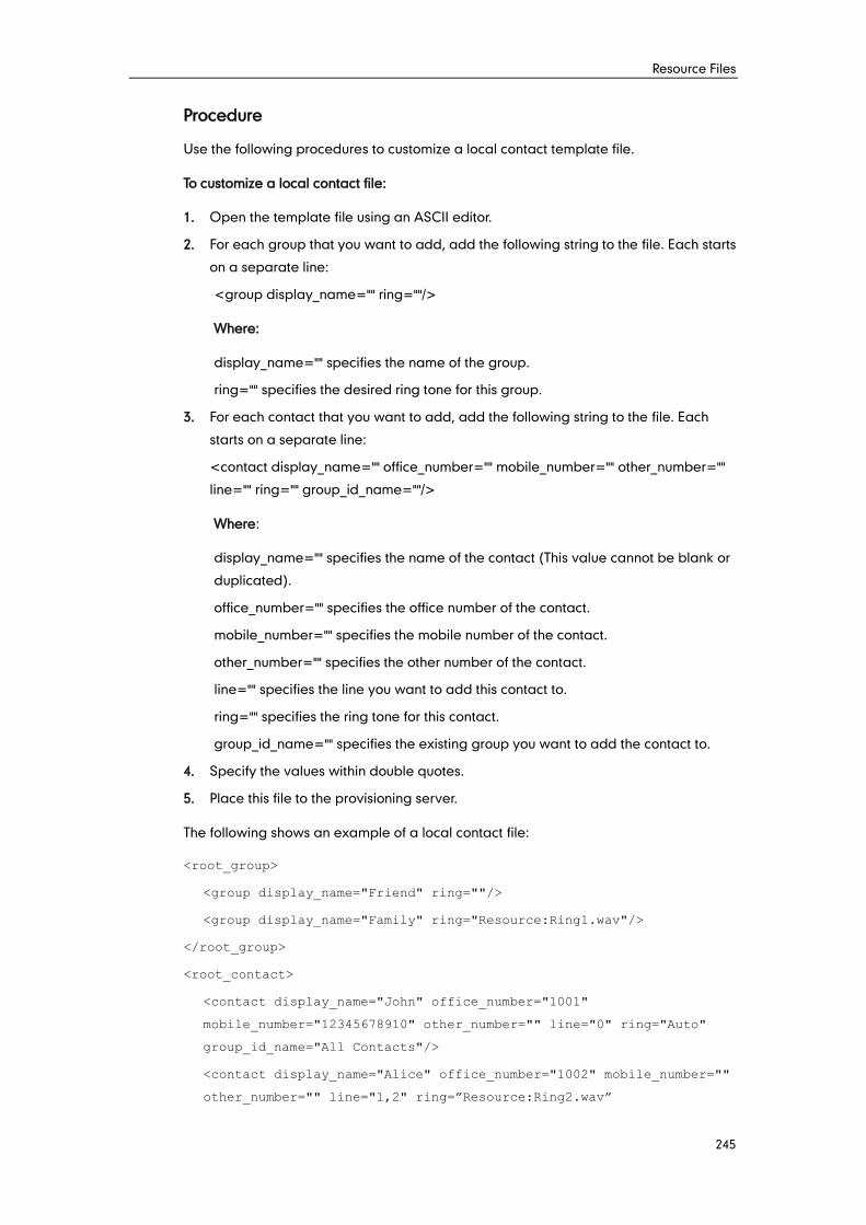
Resource Files
245
Procedure
Use the following procedures to customize a local contact template file.
To customize a local contact file:
1. Open the template file using an ASCII editor.
2. For each group that you want to add, add the following string to the file. Each starts
on a separate line:
<group display_name="" ring=""/>
Where:
display_name="" specifies the name of the group.
ring="" specifies the desired ring tone for this group.
3. For each contact that you want to add, add the following string to the file. Each
starts on a separate line:
<contact display_name="" office_number="" mobile_number="" other_number=""
line="" ring="" group_id_name=""/>
Where:
display_name="" specifies the name of the contact (This value cannot be blank or
duplicated).
office_number="" specifies the office number of the contact.
mobile_number="" specifies the mobile number of the contact.
other_number="" specifies the other number of the contact.
line="" specifies the line you want to add this contact to.
ring="" specifies the ring tone for this contact.
group_id_name="" specifies the existing group you want to add the contact to.
4. Specify the values within double quotes.
5. Place this file to the provisioning server.
The following shows an example of a local contact file:
<root_group>
<group display_name="Friend" ring=""/>
<group display_name="Family" ring="Resource:Ring1.wav"/>
</root_group>
<root_contact>
<contact display_name="John" office_number="1001"
mobile_number="12345678910" other_number="" line="0" ring="Auto"
group_id_name="All Contacts"/>
<contact display_name="Alice" office_number="1002" mobile_number=""
other_number="" line="1,2" ring=”Resource:Ring2.wav”
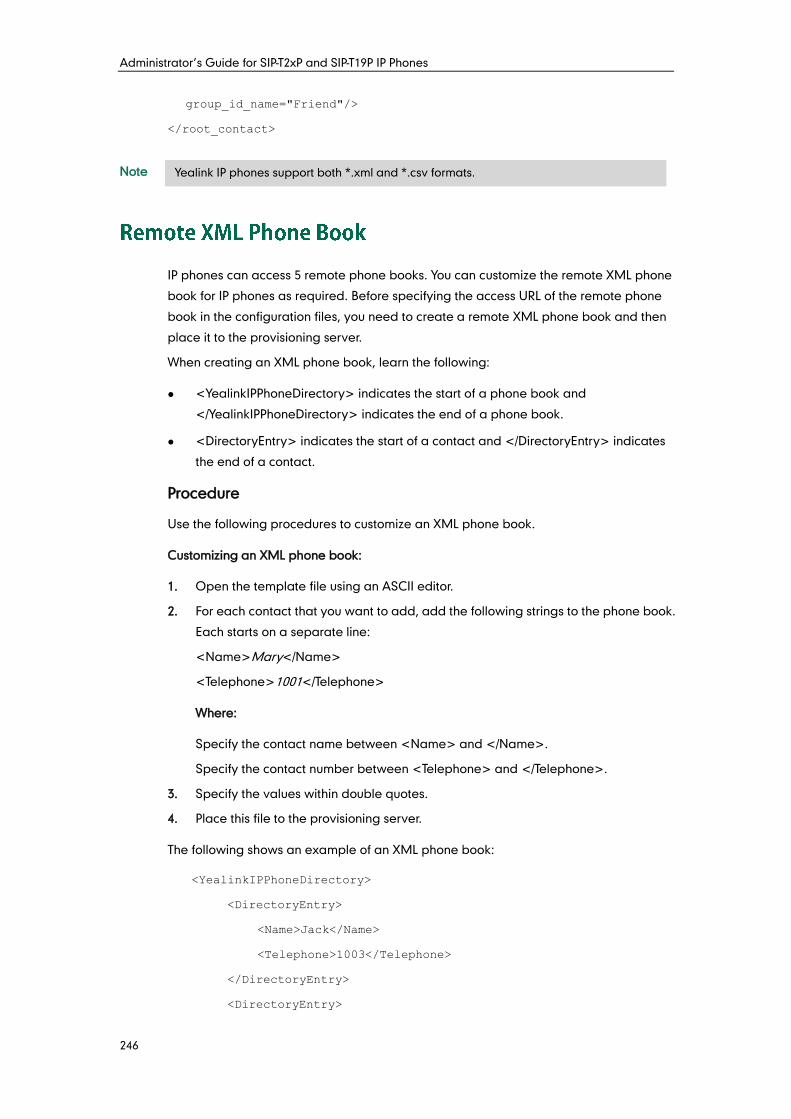
Administrator’s Guide for SIP-T2xP and SIP-T19P IP Phones
246
group_id_name="Friend"/>
</root_contact>
Note
IP phones can access 5 remote phone books. You can customize the remote XML phone
book for IP phones as required. Before specifying the access URL of the remote phone
book in the configuration files, you need to create a remote XML phone book and then
place it to the provisioning server.
When creating an XML phone book, learn the following:
<YealinkIPPhoneDirectory> indicates the start of a phone book and
</YealinkIPPhoneDirectory> indicates the end of a phone book.
<DirectoryEntry> indicates the start of a contact and </DirectoryEntry> indicates
the end of a contact.
Procedure
Use the following procedures to customize an XML phone book.
Customizing an XML phone book:
1. Open the template file using an ASCII editor.
2. For each contact that you want to add, add the following strings to the phone book.
Each starts on a separate line:
<Name>Mary</Name>
<Telephone>1001</Telephone>
Where:
Specify the contact name between <Name> and </Name>.
Specify the contact number between <Telephone> and </Telephone>.
3. Specify the values within double quotes.
4. Place this file to the provisioning server.
The following shows an example of an XML phone book:
<YealinkIPPhoneDirectory>
<DirectoryEntry>
<Name>Jack</Name>
<Telephone>1003</Telephone>
</DirectoryEntry>
<DirectoryEntry>
Yealink IP phones support both *.xml and *.csv formats.
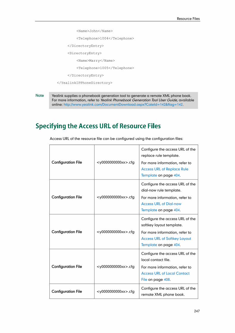
Resource Files
247
<Name>John</Name>
<Telephone>1004</Telephone>
</DirectoryEntry>
<DirectoryEntry>
<Name>Marry</Name>
<Telephone>1005</Telephone>
</DirectoryEntry>
</YealinkIPPhoneDirectory>
Note
Access URL of the resource file can be configured using the configuration files:
Configuration File <y0000000000xx>.cfg
Configure the access URL of the
replace rule template.
For more information, refer to
Access URL of Replace Rule
Template on page 404.
Configuration File <y0000000000xx>.cfg
Configure the access URL of the
dial-now rule template.
For more information, refer to
Access URL of Dial-now
Template on page 404.
Configuration File <y0000000000xx>.cfg
Configure the access URL of the
softkey layout template.
For more information, refer to
Access URL of Softkey Layout
Template on page 404.
Configuration File <y0000000000xx>.cfg
Configure the access URL of the
local contact file.
For more information, refer to
Access URL of Local Contact
File on page 408.
Configuration File <y0000000000xx>.cfg Configure the access URL of the
remote XML phone book.
Yealink supplies a phonebook generation tool to generate a remote XML phone book.
For more information, refer to Yealink Phonebook Generation Tool User Guide, available
online: http://www.yealink.com/DocumentDownload.aspx?CateId=142&flag=142.
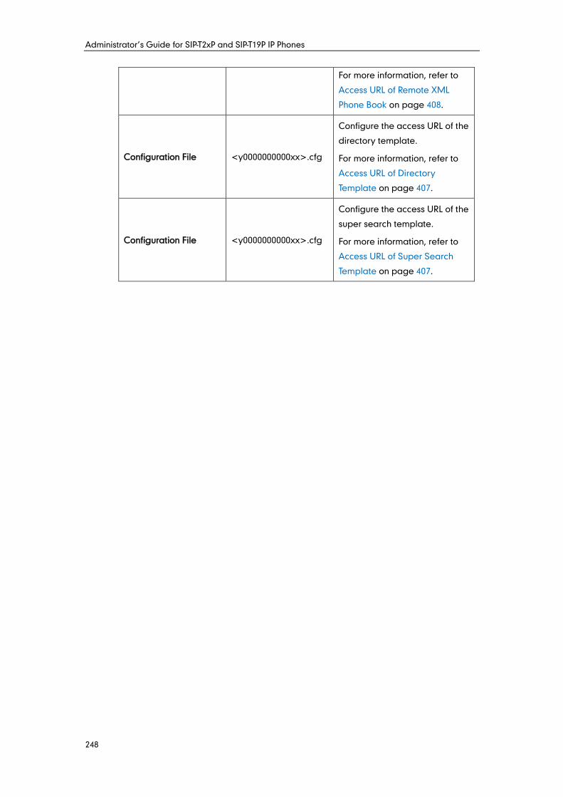
Administrator’s Guide for SIP-T2xP and SIP-T19P IP Phones
248
For more information, refer to
Access URL of Remote XML
Phone Book on page 408.
Configuration File <y0000000000xx>.cfg
Configure the access URL of the
directory template.
For more information, refer to
Access URL of Directory
Template on page 407.
Configuration File <y0000000000xx>.cfg
Configure the access URL of the
super search template.
For more information, refer to
Access URL of Super Search
Template on page 407.

Resource Files
249
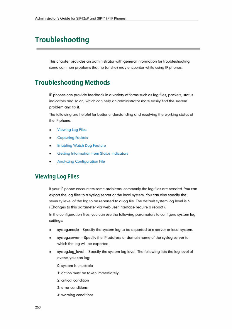
Administrator’s Guide for SIP-T2xP and SIP-T19P IP Phones
250
This chapter provides an administrator with general information for troubleshooting
some common problems that he (or she) may encounter while using IP phones.
IP phones can provide feedback in a variety of forms such as log files, packets, status
indicators and so on, which can help an administrator more easily find the system
problem and fix it.
The following are helpful for better understanding and resolving the working status of
the IP phone.
Viewing Log Files
Capturing Packets
Enabling Watch Dog Feature
Getting Information from Status Indicators
Analyzing Configuration File
If your IP phone encounters some problems, commonly the log files are needed. You can
export the log files to a syslog server or the local system. You can also specify the
severity level of the log to be reported to a log file. The default system log level is 3
(Changes to this parameter via web user interface require a reboot).
In the configuration files, you can use the following parameters to configure system log
settings:
syslog.mode – Specify the system log to be exported to a server or local system.
syslog.server -- Specify the IP address or domain name of the syslog server to
which the log will be exported.
syslog.log_level -- Specify the system log level. The following lists the log level of
events you can log:
0: system is unusable
1: action must be taken immediately
2: critical condition
3: error conditions
4: warning conditions
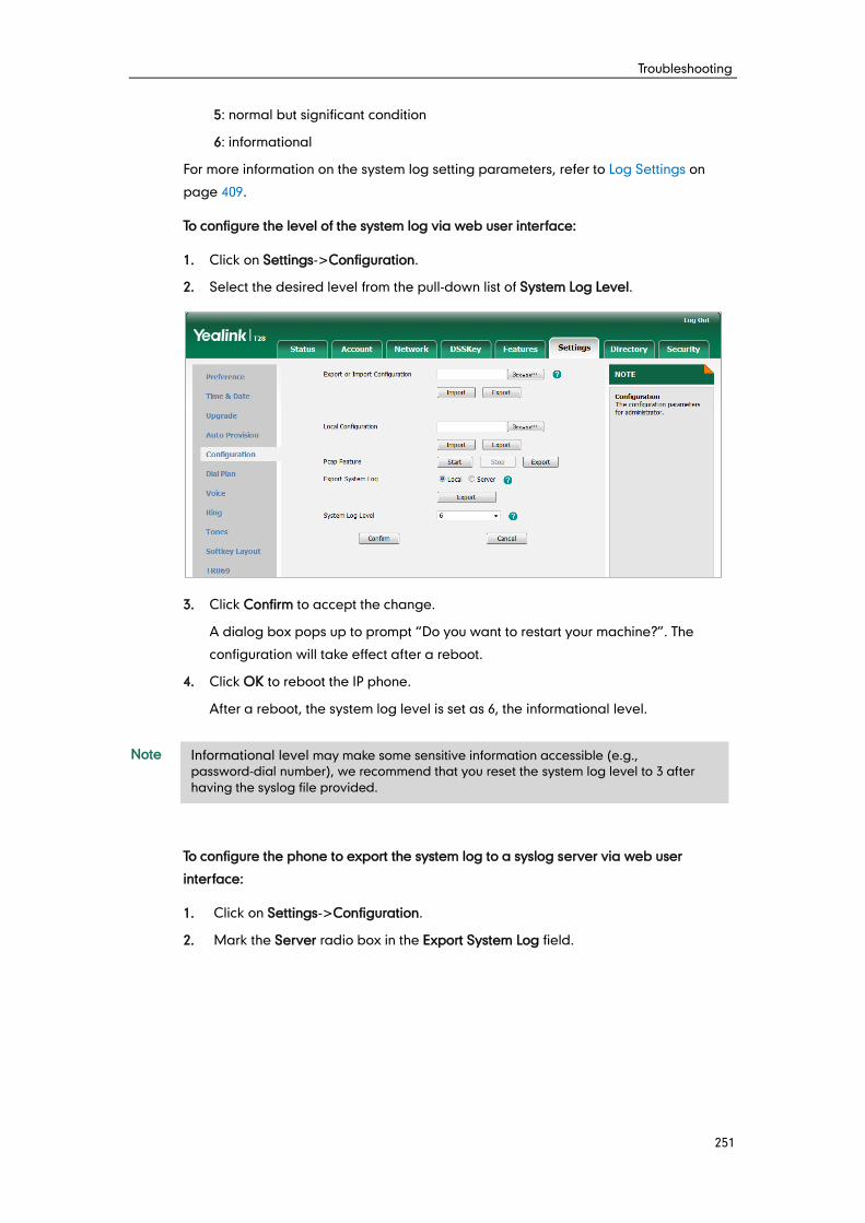
Troubleshooting
251
5: normal but significant condition
6: informational
For more information on the system log setting parameters, refer to Log Settings on
page 409.
To configure the level of the system log via web user interface:
1. Click on Settings->Configuration.
2. Select the desired level from the pull-down list of System Log Level.
3. Click Confirm to accept the change.
A dialog box pops up to prompt “Do you want to restart your machine?”. The
configuration will take effect after a reboot.
4. Click OK to reboot the IP phone.
After a reboot, the system log level is set as 6, the informational level.
Note
To configure the phone to export the system log to a syslog server via web user
interface:
1. Click on Settings->Configuration.
2. Mark the Server radio box in the Export System Log field.
Informational level may make some sensitive information accessible (e.g.,
password-dial number), we recommend that you reset the system log level to 3 after
having the syslog file provided.
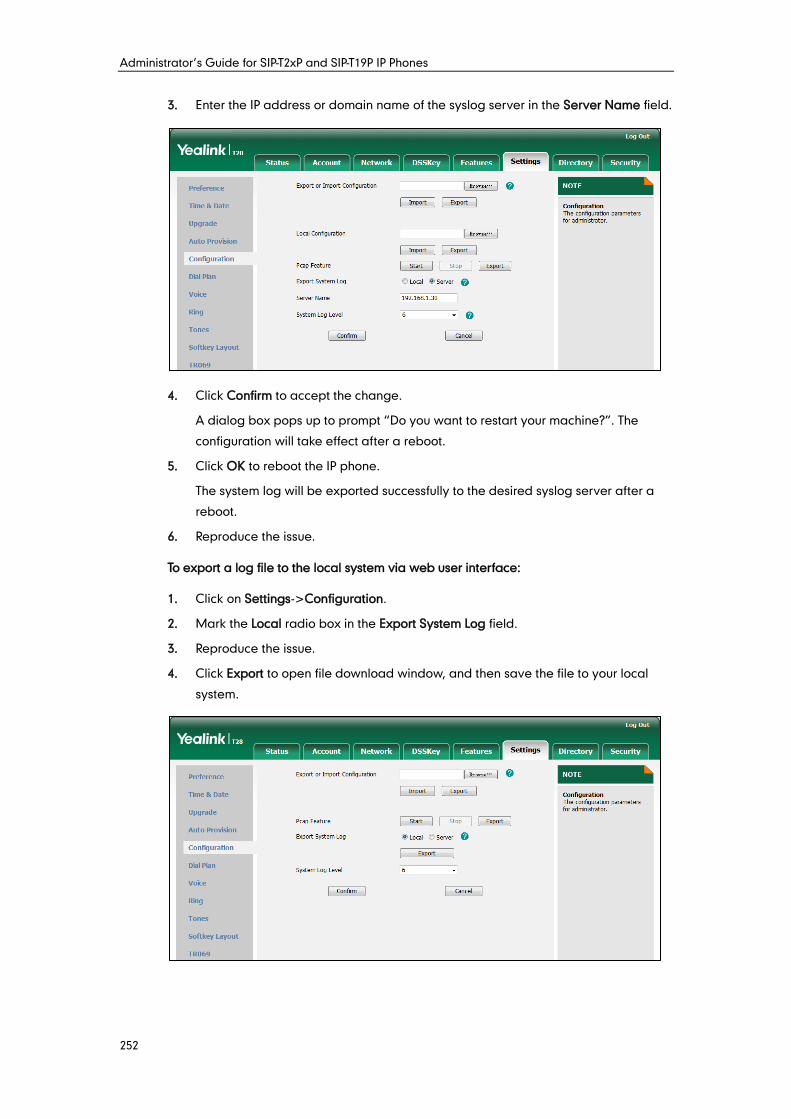
Administrator’s Guide for SIP-T2xP and SIP-T19P IP Phones
252
3. Enter the IP address or domain name of the syslog server in the Server Name field.
4. Click Confirm to accept the change.
A dialog box pops up to prompt “Do you want to restart your machine?”. The
configuration will take effect after a reboot.
5. Click OK to reboot the IP phone.
The system log will be exported successfully to the desired syslog server after a
reboot.
6. Reproduce the issue.
To export a log file to the local system via web user interface:
1. Click on Settings->Configuration.
2. Mark the Local radio box in the Export System Log field.
3. Reproduce the issue.
4. Click Export to open file download window, and then save the file to your local
system.
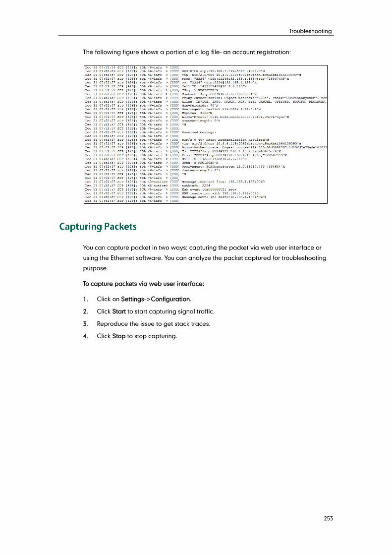
Troubleshooting
253
The following figure shows a portion of a log file- an account registration:
You can capture packet in two ways: capturing the packet via web user interface or
using the Ethernet software. You can analyze the packet captured for troubleshooting
purpose.
To capture packets via web user interface:
1. Click on Settings->Configuration.
2. Click Start to start capturing signal traffic.
3. Reproduce the issue to get stack traces.
4. Click Stop to stop capturing.
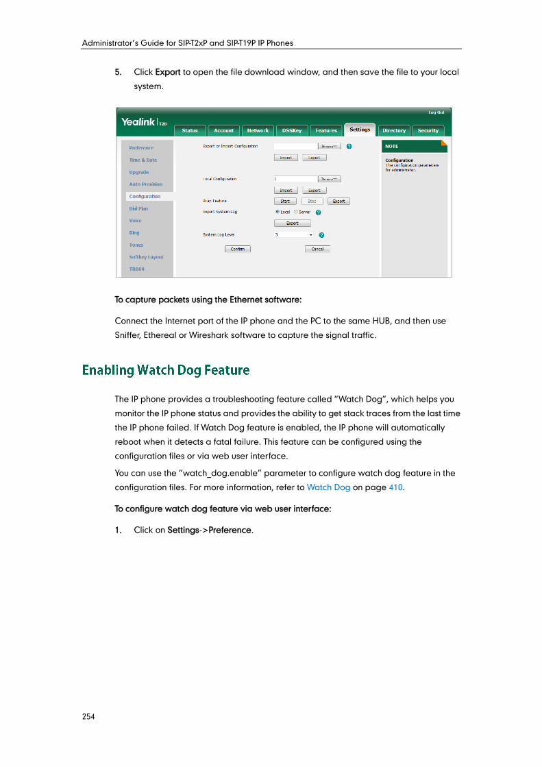
Administrator’s Guide for SIP-T2xP and SIP-T19P IP Phones
254
5. Click Export to open the file download window, and then save the file to your local
system.
To capture packets using the Ethernet software:
Connect the Internet port of the IP phone and the PC to the same HUB, and then use
Sniffer, Ethereal or Wireshark software to capture the signal traffic.
The IP phone provides a troubleshooting feature called “Watch Dog”, which helps you
monitor the IP phone status and provides the ability to get stack traces from the last time
the IP phone failed. If Watch Dog feature is enabled, the IP phone will automatically
reboot when it detects a fatal failure. This feature can be configured using the
configuration files or via web user interface.
You can use the “watch_dog.enable” parameter to configure watch dog feature in the
configuration files. For more information, refer to Watch Dog on page 410.
To configure watch dog feature via web user interface:
1. Click on Settings->Preference.
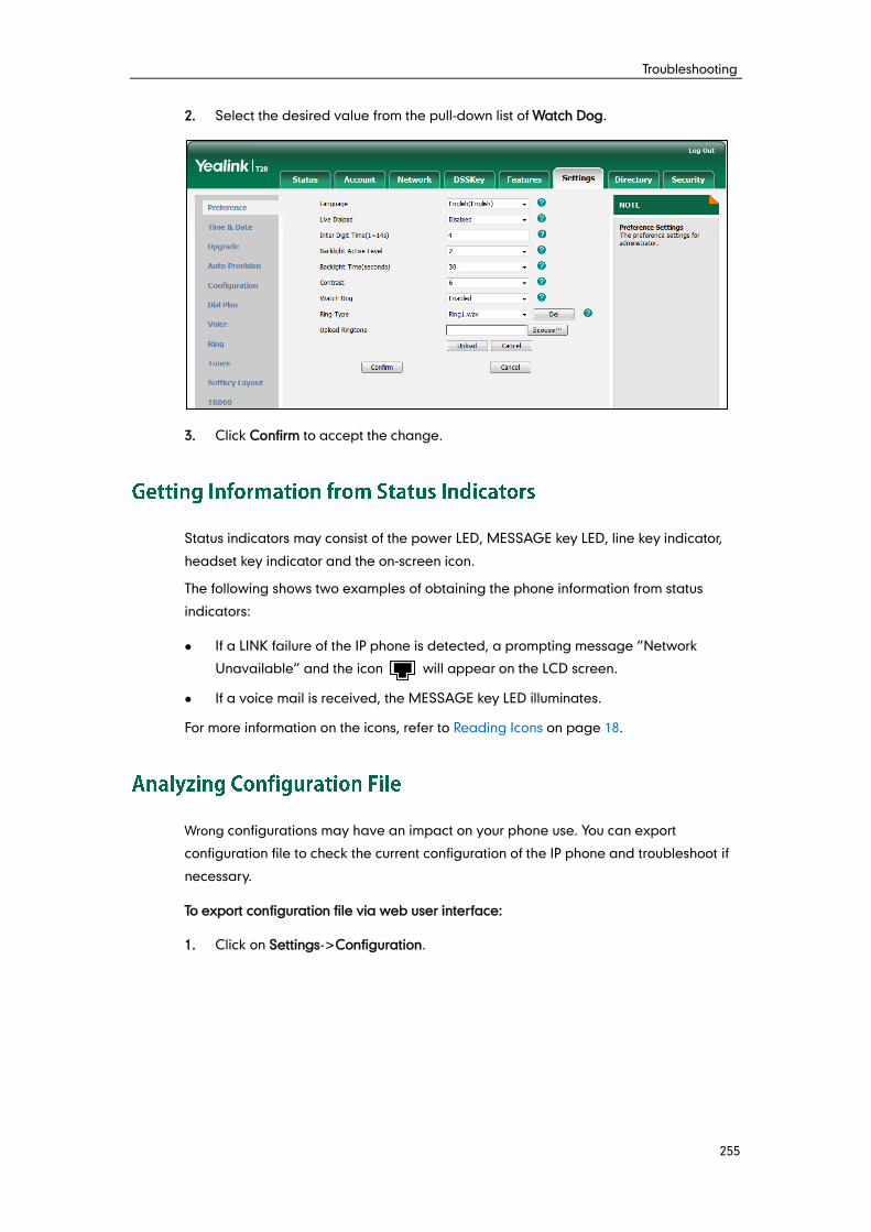
Troubleshooting
255
2. Select the desired value from the pull-down list of Watch Dog.
3. Click Confirm to accept the change.
Status indicators may consist of the power LED, MESSAGE key LED, line key indicator,
headset key indicator and the on-screen icon.
The following shows two examples of obtaining the phone information from status
indicators:
If a LINK failure of the IP phone is detected, a prompting message “Network
Unavailable” and the icon will appear on the LCD screen.
If a voice mail is received, the MESSAGE key LED illuminates.
For more information on the icons, refer to Reading Icons on page 18.
Wrong configurations may have an impact on your phone use. You can export
configuration file to check the current configuration of the IP phone and troubleshoot if
necessary.
To export configuration file via web user interface:
1. Click on Settings->Configuration.
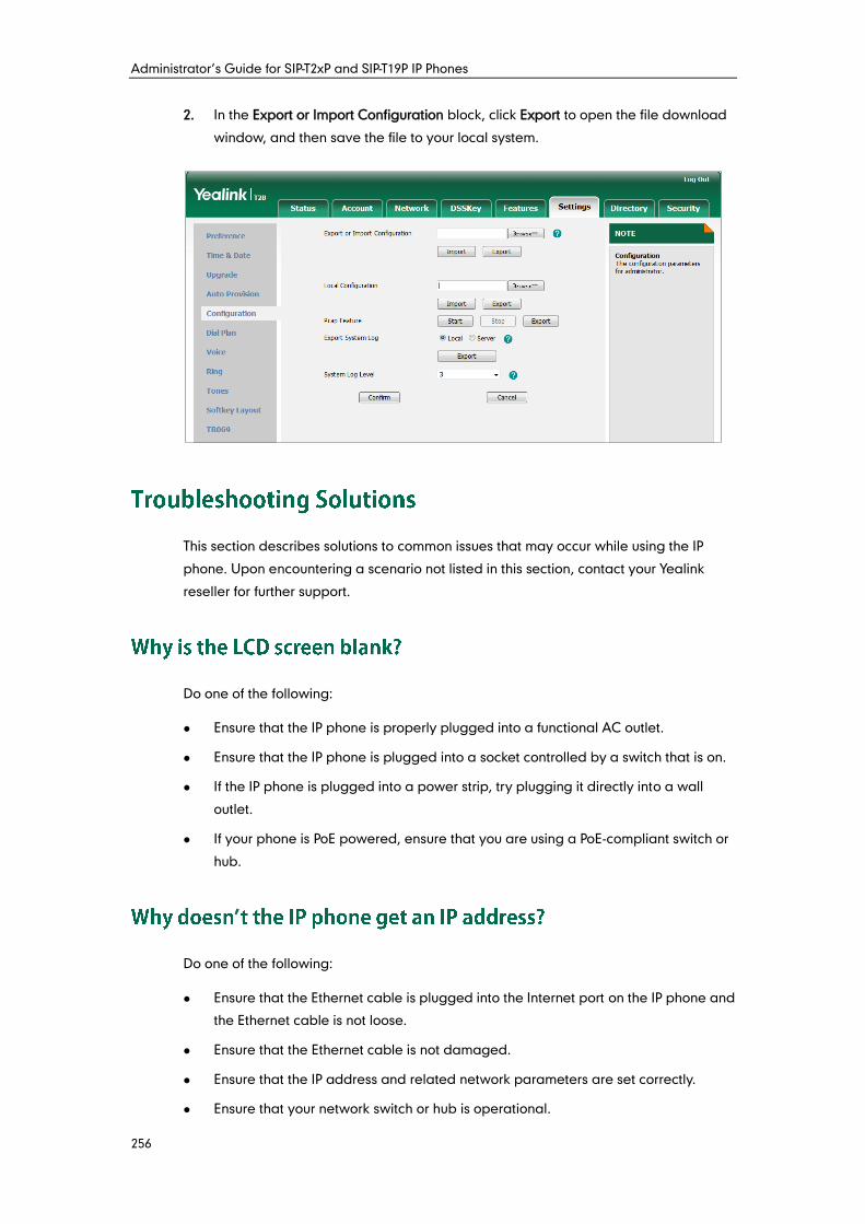
Administrator’s Guide for SIP-T2xP and SIP-T19P IP Phones
256
2. In the Export or Import Configuration block, click Export to open the file download
window, and then save the file to your local system.
This section describes solutions to common issues that may occur while using the IP
phone. Upon encountering a scenario not listed in this section, contact your Yealink
reseller for further support.
Do one of the following:
Ensure that the IP phone is properly plugged into a functional AC outlet.
Ensure that the IP phone is plugged into a socket controlled by a switch that is on.
If the IP phone is plugged into a power strip, try plugging it directly into a wall
outlet.
If your phone is PoE powered, ensure that you are using a PoE-compliant switch or
hub.
’
Do one of the following:
Ensure that the Ethernet cable is plugged into the Internet port on the IP phone and
the Ethernet cable is not loose.
Ensure that the Ethernet cable is not damaged.
Ensure that the IP address and related network parameters are set correctly.
Ensure that your network switch or hub is operational.
Troubleshooting
257
“ ”
The LCD screen prompts “No Service” message when there is no available SIP account
on the IP phone.
Do one of the following:
Ensure that an account is actively registered on the IP phone at the path
Menu->Status->More->Accounts.
Ensure that the SIP account parameters have been configured correctly.
Press the OK key when the IP phone is idle to check the basic information (e.g., IP
address, MAC address and firmware version).
’
Do one of the following:
Ensure that the target firmware is not the same as the current firmware.
Ensure that the target firmware is applicable to the IP phone model.
Ensure that the current or the target firmware is not protected.
Ensure that the power is on and the network is available in the process of
upgrading.
Ensure that the web browser is not closed or refreshed when upgrading firmware
via web user interface.
’
Check if the IP phone is configured to obtain the time and date from the NTP server
automatically. If your phone is unable to access the NTP server, configure the time and
date manually.
If you have poor sound quality/acoustics like intermittent voice, low volume, echo or
other noises, the possible reasons could be:
Users are seated too far out of recommended microphone range and sound faint,
or are seated too close to sensitive microphones and cause echo.
Intermittent voice is mainly caused by packet loss, due to network congestion, and
Administrator’s Guide for SIP-T2xP and SIP-T19P IP Phones
258
jitter, due to message recombination of transmission or receiving equipment (e.g.,
timeout handling, retransmission mechanism, buffer under run).
Noisy equipment, such as a computer or a fan, may cause voice interference. Turn
off any noisy equipment.
Line issues can also cause this problem; disconnect the old line and redial the call
to ensure another line may provide better connection.
A remote phone book is placed on a server, while a local phone book is placed on the
IP phone flash. A remote phone book can be used by everyone that can access the
server, while a local phone book can only be used by a specific phone. A remote phone
book is always used as a central phone book for a company; each employee can load
it to obtain the real-time data from the same server.
Both user name and register name are defined by the server. User name identifies the
account, while register name matched with a password is for authentication purposes.
Display name is the caller ID that will be displayed on the callee’s phone LCD screen.
Server configurations may override the local ones.
IP phones support remote reboot by a SIP NOTIFY message with “Event: check-sync”
header. When receiving a NOTIFY message with the parameter “reboot=true”, the IP
phone reboots immediately. The NOTIFY message is formed as shown:
NOTIFY sip:<user>@<dsthost> SIP/2.0
To: sip:<user>@<dsthost>
From: sip:sipsak@<srchost>
CSeq: 10 NOTIFY
Call-ID: 1234@<srchost>
Event: check-sync;reboot=true
Troubleshooting
259
The IP phone only uses logo file in DOB format, as the DOB format file has a high
compression ratio (the size of the uncompressed file compared to that of the
compressed file) and can be stored in smaller space. Tools for converting BMP format to
DOB format are available. For more information, refer to
Yealink_SIP-T2_Series_T19P_T4_Series_IP_Phones_Auto_Provisioning_Guide, available
online: http://www.yealink.com/DocumentDownload.aspx?CateId=142&flag=142.
Press the volume key to increase or decrease the ringer volume when the phone is idle,
or to adjust the volume of engaged audio device (handset, speakerphone or headset)
when there is an active call in progress.
IP phones manufactured before February 2010 will use the power adapter preferentially,
while those made later will use PoE preferentially.
Auto provisioning refers to the update of IP phones, including update on configuration
parameters, local phone book, firmware and so on. You can use auto provisioning on a
single phone, but it makes more sense in mass deployment.
Plug and Play (PnP) is a method for IP phones to acquire the provisioning server address.
With PnP enabled, the IP phone broadcasts the PnP SUBSCRIBE message to obtain a
provisioning server address during startup. Any SIP server recognizing the message will
respond with the preconfigured provisioning server address, so the IP phone will be
able to download the CFG files from the provisioning server. PnP depends on support
from a SIP server.

Administrator’s Guide for SIP-T2xP and SIP-T19P IP Phones
260
’
Do one of the following:
Ensure that the configuration is set correctly.
Reboot the IP phone. Some configurations require a reboot to take effect.
Ensure that the configuration is applicable to the IP phone model.
The configuration may depend on support from a server.
“ ” “ ”
They are codes that the IP phone sends to the server when a certain action takes place.
On code is used to activate a feature on the server side, while off code is used to
deactivate a feature on the server side.
For example, if you set the Always Forward on code to be *78 (may vary on different
servers), and the target number to be 201. When you enable Always Forward on the IP
phone, the IP phone sends *78201 to the server, and then the server will enable Always
Forward feature on the server side, hence being able to get the right status of the
extension.
Do one of the following:
Reset another available IP address for the IP phone.
Check network configuration via phone user interface at the path
Menu->Settings->Advanced Settings->Network->WAN Port->IPv4. If Static IP
Client is selected, select DHCP IP Client instead.
Reset your phone to factory configurations after you have tried all troubleshooting
suggestions but do not solve the problem. Note that all custom settings will be
overwritten after resetting.
To reset the IP phone via web user interface:
1. Click on Settings->Upgrade.
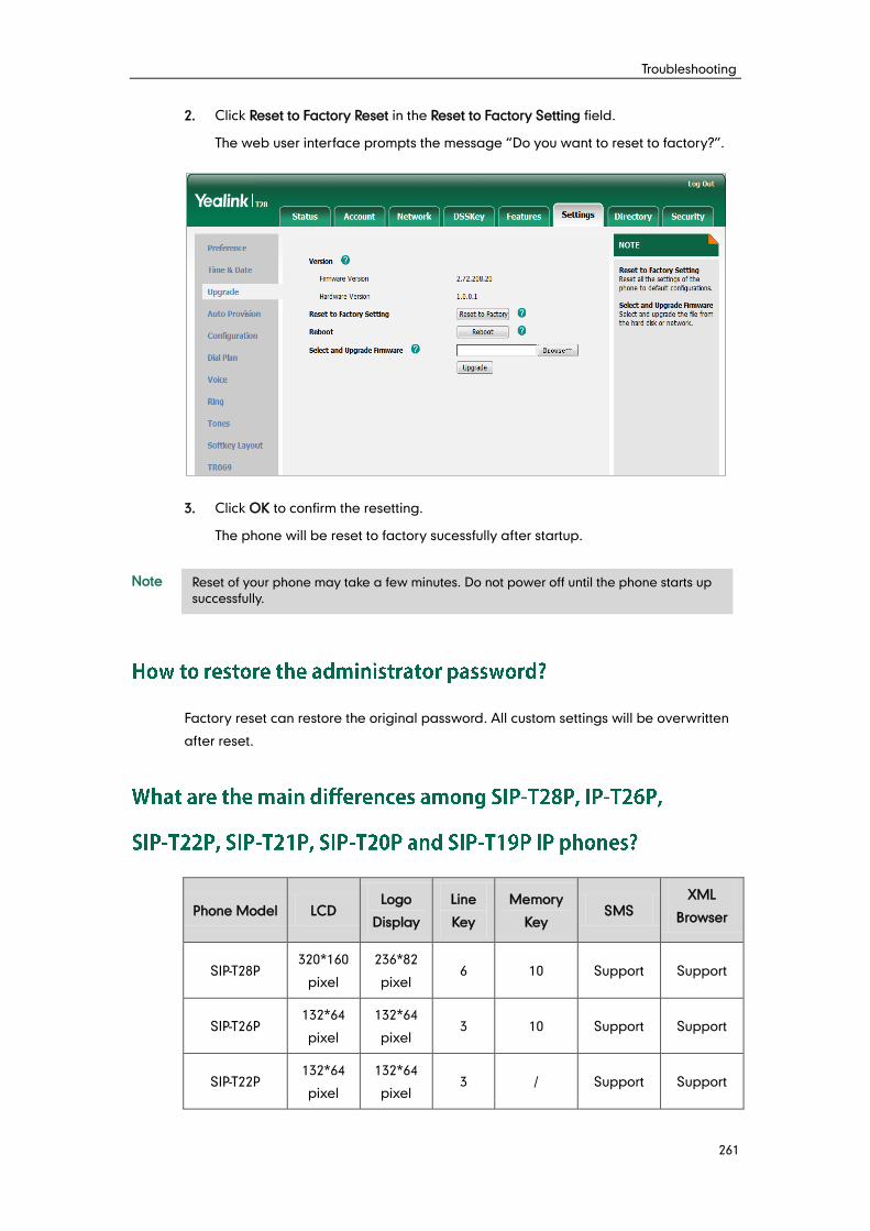
Troubleshooting
261
2. Click Reset to Factory Reset in the Reset to Factory Setting field.
The web user interface prompts the message “Do you want to reset to factory?”.
3. Click OK to confirm the resetting.
The phone will be reset to factory sucessfully after startup.
Note
Factory reset can restore the original password. All custom settings will be overwritten
after reset.
Phone Model LCD Logo
Display
Line
Key
Memory
Key SMS
XML
Browser
SIP-T28P 320*160
pixel
236*82
pixel 6 10 Support Support
SIP-T26P 132*64
pixel
132*64
pixel 3 10 Support Support
SIP-T22P 132*64
pixel
132*64
pixel 3 / Support Support
Reset of your phone may take a few minutes. Do not power off until the phone starts up
successfully.
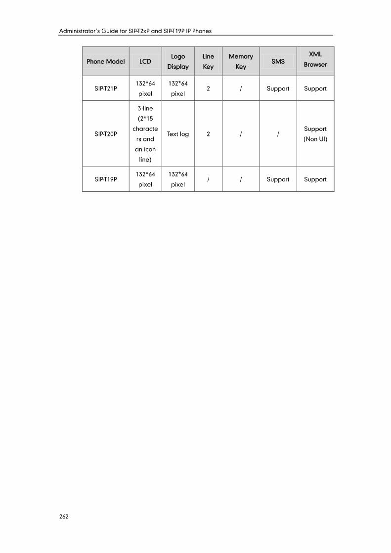
Administrator’s Guide for SIP-T2xP and SIP-T19P IP Phones
262
Phone Model LCD Logo
Display
Line
Key
Memory
Key SMS
XML
Browser
SIP-T21P 132*64
pixel
132*64
pixel 2 / Support Support
SIP-T20P
3-line
(2*15
characte
rs and
an icon
line)
Text log 2 / / Support
(Non UI)
SIP-T19P 132*64
pixel
132*64
pixel / / Support Support

Troubleshooting
263
Administrator’s Guide for SIP-T2xP and SIP-T19P IP Phones
264
802.1x--an IEEE Standard for port-based Network Access Control (PNAC). It is a part of
the IEEE 802.1 group of networking protocols. It provides an authentication mechanism
to devices wishing to attach to a LAN or WLAN.
ACD (Automatic Call Distribution)--used to distribute calls from large volumes of
incoming calls to the registered IP phone users.
ACS (Auto Configuration server)--responsible for auto-configuration of the Central
Processing Element (CPE).
Cryptographic Key--a piece of variable data that is fed as input into a cryptographic
algorithm to perform operations such as encryption and decryption, or signing and
verification.
DHCP (Dynamic Host Configuration Protocol)--built on a client-server model, where
designated DHCP server hosts allocate network addresses and deliver configuration
parameters to dynamically configured hosts.
DHCP Option--can be configured for specific values and enabled for assignment and
distribution to DHCP clients based on server, scope, class or client-specific levels.
DNS (Domain Name System)--a hierarchical distributed naming system for computers,
services, or any resource connected to the Internet or a private network.
EAP-MD5 (Extensible Authentication Protocol-Message Digest Algorithm 5)--only
provides authentication of the EAP peer to the EAP server but not mutual authentication.
EAP-TLS (Extensible Authentication Protocol-Transport Layer Security) –provides for
mutual authentication, integrity-protected cipher suite negotiation between two
endpoints.
PEAP-MSCHAPv2 (Protected Extensible Authentication Protocol-Microsoft Challenge
Handshake Authentication Protocol version 2) –provides for mutual authentication, but
does not require a client certificate on the IP phone.
FAC (Feature Access Code)--special patterns of characters that are dialed from a
phone keypad to invoke particular features.
HTTP (Hypertext Transfer Protocol)--used to request and transmit data on the World
Wide Web.
HTTPS (Hypertext Transfer Protocol over Secure Socket Layer)--a widely-used
communications protocol for secure communication over a network.
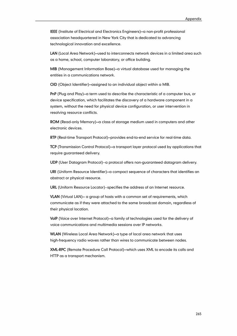
Appendix
265
IEEE (Institute of Electrical and Electronics Engineers)--a non-profit professional
association headquartered in New York City that is dedicated to advancing
technological innovation and excellence.
LAN (Local Area Network)--used to interconnects network devices in a limited area such
as a home, school, computer laboratory, or office building.
MIB (Management Information Base)--a virtual database used for managing the
entities in a communications network.
OID (Object Identifier)--assigned to an individual object within a MIB.
PnP (Plug and Play)--a term used to describe the characteristic of a computer bus, or
device specification, which facilitates the discovery of a hardware component in a
system, without the need for physical device configuration, or user intervention in
resolving resource conflicts.
ROM (Read-only Memory)--a class of storage medium used in computers and other
electronic devices.
RTP (Real-time Transport Protocol)--provides end-to-end service for real-time data.
TCP (Transmission Control Protocol)--a transport layer protocol used by applications that
require guaranteed delivery.
UDP (User Datagram Protocol)--a protocol offers non-guaranteed datagram delivery.
URI (Uniform Resource Identifier)--a compact sequence of characters that identifies an
abstract or physical resource.
URL (Uniform Resource Locator)--specifies the address of an Internet resource.
VLAN (Virtual LAN)-- a group of hosts with a common set of requirements, which
communicate as if they were attached to the same broadcast domain, regardless of
their physical location.
VoIP (Voice over Internet Protocol)--a family of technologies used for the delivery of
voice communications and multimedia sessions over IP networks.
WLAN (Wireless Local Area Network)--a type of local area network that uses
high-frequency radio waves rather than wires to communicate between nodes.
XML-RPC (Remote Procedure Call Protocol)--which uses XML to encode its calls and
HTTP as a transport mechanism.
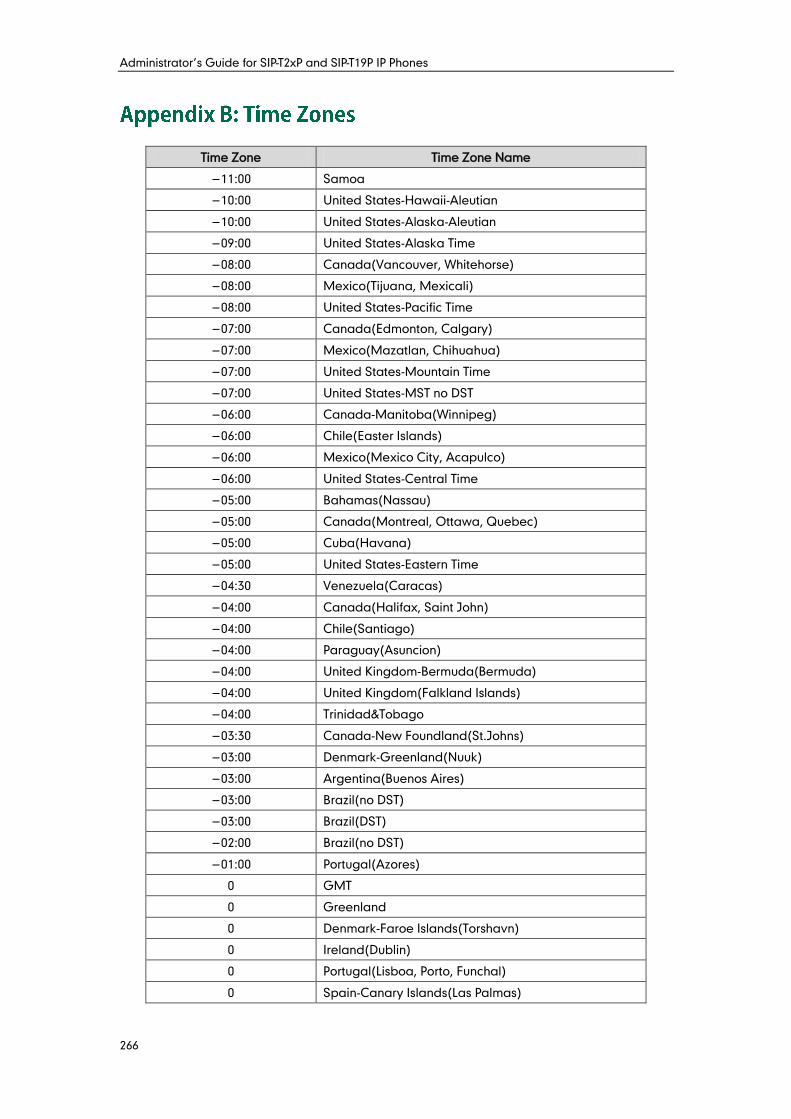
Administrator’s Guide for SIP-T2xP and SIP-T19P IP Phones
266
Time Zone Time Zone Name
−11:00 Samoa
−10:00 United States-Hawaii-Aleutian
−10:00 United States-Alaska-Aleutian
−09:00 United States-Alaska Time
−08:00 Canada(Vancouver, Whitehorse)
−08:00 Mexico(Tijuana, Mexicali)
−08:00 United States-Pacific Time
−07:00 Canada(Edmonton, Calgary)
−07:00 Mexico(Mazatlan, Chihuahua)
−07:00 United States-Mountain Time
−07:00 United States-MST no DST
−06:00 Canada-Manitoba(Winnipeg)
−06:00 Chile(Easter Islands)
−06:00 Mexico(Mexico City, Acapulco)
−06:00 United States-Central Time
−05:00 Bahamas(Nassau)
−05:00 Canada(Montreal, Ottawa, Quebec)
−05:00 Cuba(Havana)
−05:00 United States-Eastern Time
−04:30 Venezuela(Caracas)
−04:00 Canada(Halifax, Saint John)
−04:00 Chile(Santiago)
−04:00 Paraguay(Asuncion)
−04:00 United Kingdom-Bermuda(Bermuda)
−04:00 United Kingdom(Falkland Islands)
−04:00 Trinidad&Tobago
−03:30 Canada-New Foundland(St.Johns)
−03:00 Denmark-Greenland(Nuuk)
−03:00 Argentina(Buenos Aires)
−03:00 Brazil(no DST)
−03:00 Brazil(DST)
−02:00 Brazil(no DST)
−01:00 Portugal(Azores)
0 GMT
0 Greenland
0 Denmark-Faroe Islands(Torshavn)
0 Ireland(Dublin)
0 Portugal(Lisboa, Porto, Funchal)
0 Spain-Canary Islands(Las Palmas)
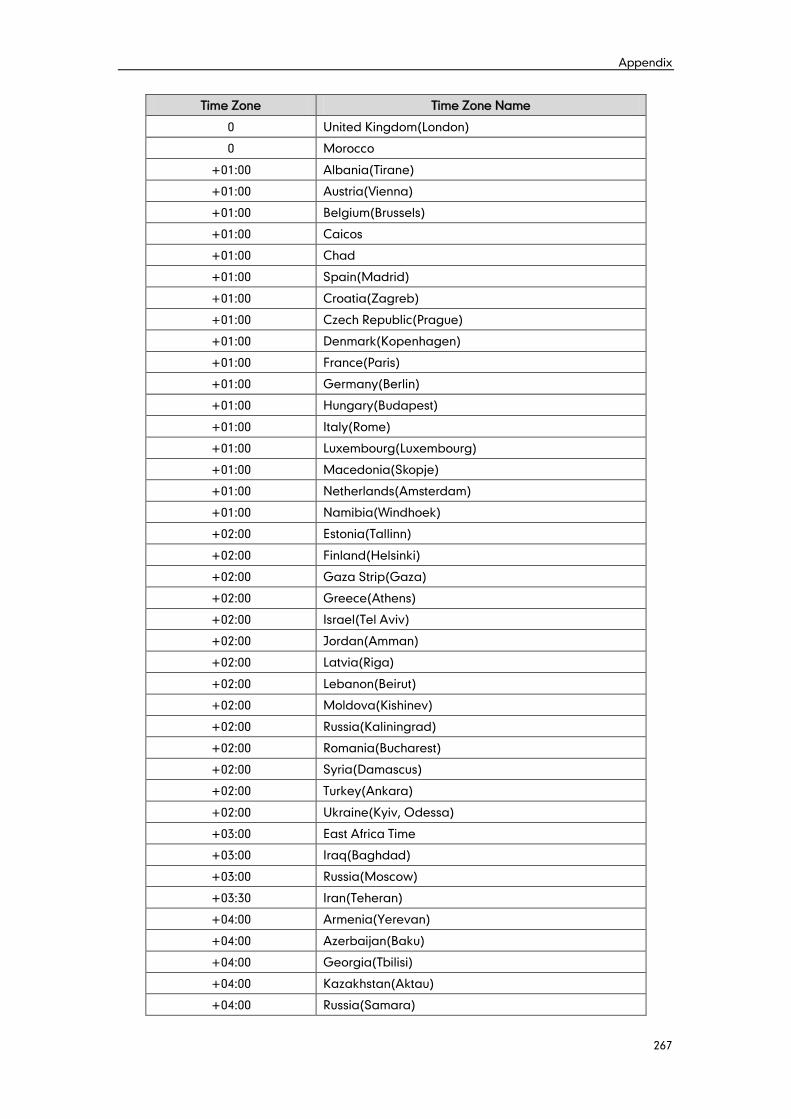
Appendix
267
Time Zone Time Zone Name
0 United Kingdom(London)
0 Morocco
+01:00 Albania(Tirane)
+01:00 Austria(Vienna)
+01:00 Belgium(Brussels)
+01:00 Caicos
+01:00 Chad
+01:00 Spain(Madrid)
+01:00 Croatia(Zagreb)
+01:00 Czech Republic(Prague)
+01:00 Denmark(Kopenhagen)
+01:00 France(Paris)
+01:00 Germany(Berlin)
+01:00 Hungary(Budapest)
+01:00 Italy(Rome)
+01:00 Luxembourg(Luxembourg)
+01:00 Macedonia(Skopje)
+01:00 Netherlands(Amsterdam)
+01:00 Namibia(Windhoek)
+02:00 Estonia(Tallinn)
+02:00 Finland(Helsinki)
+02:00 Gaza Strip(Gaza)
+02:00 Greece(Athens)
+02:00 Israel(Tel Aviv)
+02:00 Jordan(Amman)
+02:00 Latvia(Riga)
+02:00 Lebanon(Beirut)
+02:00 Moldova(Kishinev)
+02:00 Russia(Kaliningrad)
+02:00 Romania(Bucharest)
+02:00 Syria(Damascus)
+02:00 Turkey(Ankara)
+02:00 Ukraine(Kyiv, Odessa)
+03:00 East Africa Time
+03:00 Iraq(Baghdad)
+03:00 Russia(Moscow)
+03:30 Iran(Teheran)
+04:00 Armenia(Yerevan)
+04:00 Azerbaijan(Baku)
+04:00 Georgia(Tbilisi)
+04:00 Kazakhstan(Aktau)
+04:00 Russia(Samara)
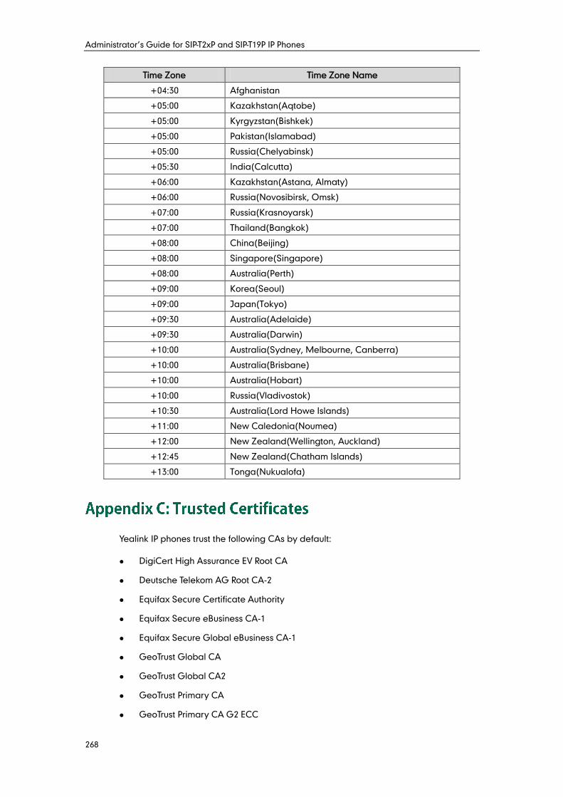
Administrator’s Guide for SIP-T2xP and SIP-T19P IP Phones
268
Time Zone Time Zone Name
+04:30 Afghanistan
+05:00 Kazakhstan(Aqtobe)
+05:00 Kyrgyzstan(Bishkek)
+05:00 Pakistan(Islamabad)
+05:00 Russia(Chelyabinsk)
+05:30 India(Calcutta)
+06:00 Kazakhstan(Astana, Almaty)
+06:00 Russia(Novosibirsk, Omsk)
+07:00 Russia(Krasnoyarsk)
+07:00 Thailand(Bangkok)
+08:00 China(Beijing)
+08:00 Singapore(Singapore)
+08:00 Australia(Perth)
+09:00 Korea(Seoul)
+09:00 Japan(Tokyo)
+09:30 Australia(Adelaide)
+09:30 Australia(Darwin)
+10:00 Australia(Sydney, Melbourne, Canberra)
+10:00 Australia(Brisbane)
+10:00 Australia(Hobart)
+10:00 Russia(Vladivostok)
+10:30 Australia(Lord Howe Islands)
+11:00 New Caledonia(Noumea)
+12:00 New Zealand(Wellington, Auckland)
+12:45 New Zealand(Chatham Islands)
+13:00 Tonga(Nukualofa)
Yealink IP phones trust the following CAs by default:
DigiCert High Assurance EV Root CA
Deutsche Telekom AG Root CA-2
Equifax Secure Certificate Authority
Equifax Secure eBusiness CA-1
Equifax Secure Global eBusiness CA-1
GeoTrust Global CA
GeoTrust Global CA2
GeoTrust Primary CA
GeoTrust Primary CA G2 ECC
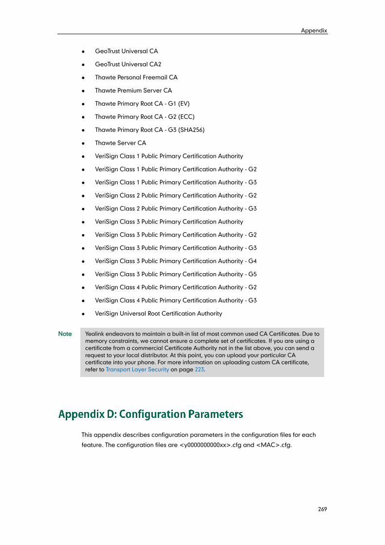
Appendix
269
GeoTrust Universal CA
GeoTrust Universal CA2
Thawte Personal Freemail CA
Thawte Premium Server CA
Thawte Primary Root CA - G1 (EV)
Thawte Primary Root CA - G2 (ECC)
Thawte Primary Root CA - G3 (SHA256)
Thawte Server CA
VeriSign Class 1 Public Primary Certification Authority
VeriSign Class 1 Public Primary Certification Authority - G2
VeriSign Class 1 Public Primary Certification Authority - G3
VeriSign Class 2 Public Primary Certification Authority - G2
VeriSign Class 2 Public Primary Certification Authority - G3
VeriSign Class 3 Public Primary Certification Authority
VeriSign Class 3 Public Primary Certification Authority - G2
VeriSign Class 3 Public Primary Certification Authority - G3
VeriSign Class 3 Public Primary Certification Authority - G4
VeriSign Class 3 Public Primary Certification Authority - G5
VeriSign Class 4 Public Primary Certification Authority - G2
VeriSign Class 4 Public Primary Certification Authority - G3
VeriSign Universal Root Certification Authority
Note
This appendix describes configuration parameters in the configuration files for each
feature. The configuration files are <y0000000000xx>.cfg and <MAC>.cfg.
Yealink endeavors to maintain a built-in list of most common used CA Certificates. Due to
memory constraints, we cannot ensure a complete set of certificates. If you are using a
certificate from a commercial Certificate Authority not in the list above, you can send a
request to your local distributor. At this point, you can upload your particular CA
certificate into your phone. For more information on uploading custom CA certificate,
refer to Transport Layer Security on page 223.
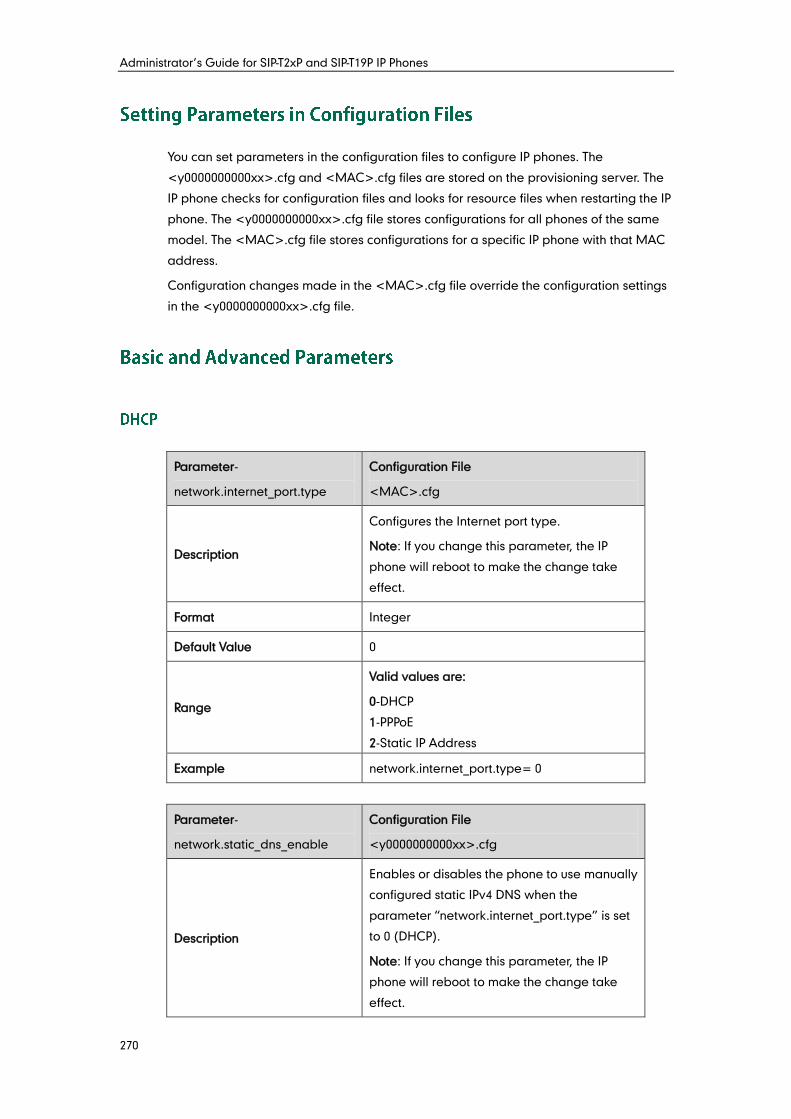
Administrator’s Guide for SIP-T2xP and SIP-T19P IP Phones
270
You can set parameters in the configuration files to configure IP phones. The
<y0000000000xx>.cfg and <MAC>.cfg files are stored on the provisioning server. The
IP phone checks for configuration files and looks for resource files when restarting the IP
phone. The <y0000000000xx>.cfg file stores configurations for all phones of the same
model. The <MAC>.cfg file stores configurations for a specific IP phone with that MAC
address.
Configuration changes made in the <MAC>.cfg file override the configuration settings
in the <y0000000000xx>.cfg file.
Parameter-
network.internet_port.type
Configuration File
<MAC>.cfg
Description
Configures the Internet port type.
Note: If you change this parameter, the IP
phone will reboot to make the change take
effect.
Format Integer
Default Value 0
Range
Valid values are:
0-DHCP
1-PPPoE
2-Static IP Address
Example network.internet_port.type= 0
Parameter-
network.static_dns_enable
Configuration File
<y0000000000xx>.cfg
Description
Enables or disables the phone to use manually
configured static IPv4 DNS when the
parameter “network.internet_port.type” is set
to 0 (DHCP).
Note: If you change this parameter, the IP
phone will reboot to make the change take
effect.
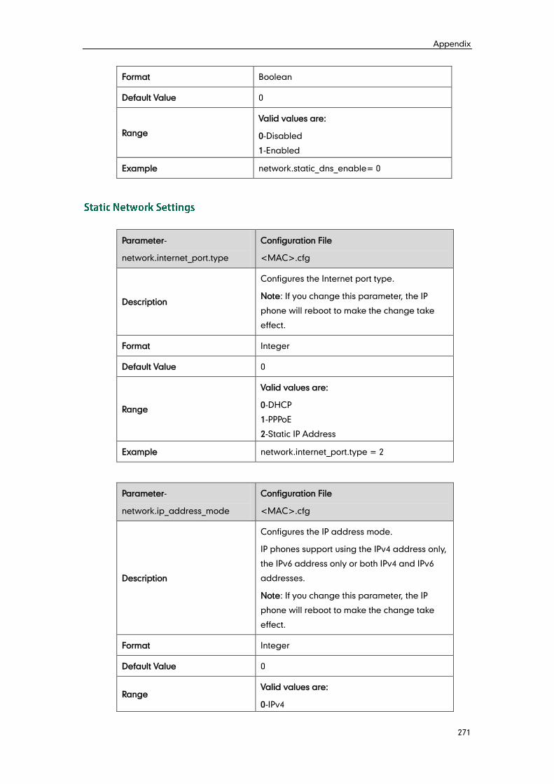
Appendix
271
Format Boolean
Default Value 0
Range
Valid values are:
0-Disabled
1-Enabled
Example network.static_dns_enable= 0
Parameter-
network.internet_port.type
Configuration File
<MAC>.cfg
Description
Configures the Internet port type.
Note: If you change this parameter, the IP
phone will reboot to make the change take
effect.
Format Integer
Default Value 0
Range
Valid values are:
0-DHCP
1-PPPoE
2-Static IP Address
Example network.internet_port.type = 2
Parameter-
network.ip_address_mode
Configuration File
<MAC>.cfg
Description
Configures the IP address mode.
IP phones support using the IPv4 address only,
the IPv6 address only or both IPv4 and IPv6
addresses.
Note: If you change this parameter, the IP
phone will reboot to make the change take
effect.
Format Integer
Default Value 0
Range Valid values are:
0-IPv4
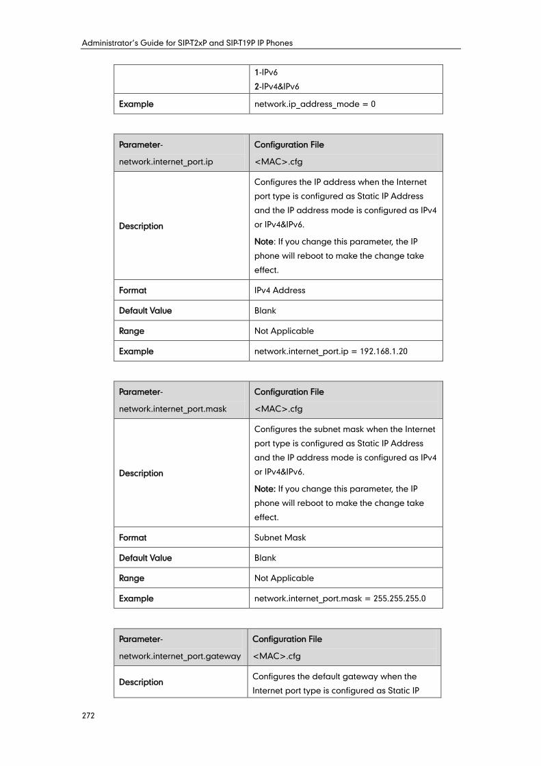
Administrator’s Guide for SIP-T2xP and SIP-T19P IP Phones
272
1-IPv6
2-IPv4&IPv6
Example network.ip_address_mode = 0
Parameter-
network.internet_port.ip
Configuration File
<MAC>.cfg
Description
Configures the IP address when the Internet
port type is configured as Static IP Address
and the IP address mode is configured as IPv4
or IPv4&IPv6.
Note: If you change this parameter, the IP
phone will reboot to make the change take
effect.
Format IPv4 Address
Default Value Blank
Range Not Applicable
Example network.internet_port.ip = 192.168.1.20
Parameter-
network.internet_port.mask
Configuration File
<MAC>.cfg
Description
Configures the subnet mask when the Internet
port type is configured as Static IP Address
and the IP address mode is configured as IPv4
or IPv4&IPv6.
Note: If you change this parameter, the IP
phone will reboot to make the change take
effect.
Format Subnet Mask
Default Value Blank
Range Not Applicable
Example network.internet_port.mask = 255.255.255.0
Parameter-
network.internet_port.gateway
Configuration File
<MAC>.cfg
Description Configures the default gateway when the
Internet port type is configured as Static IP
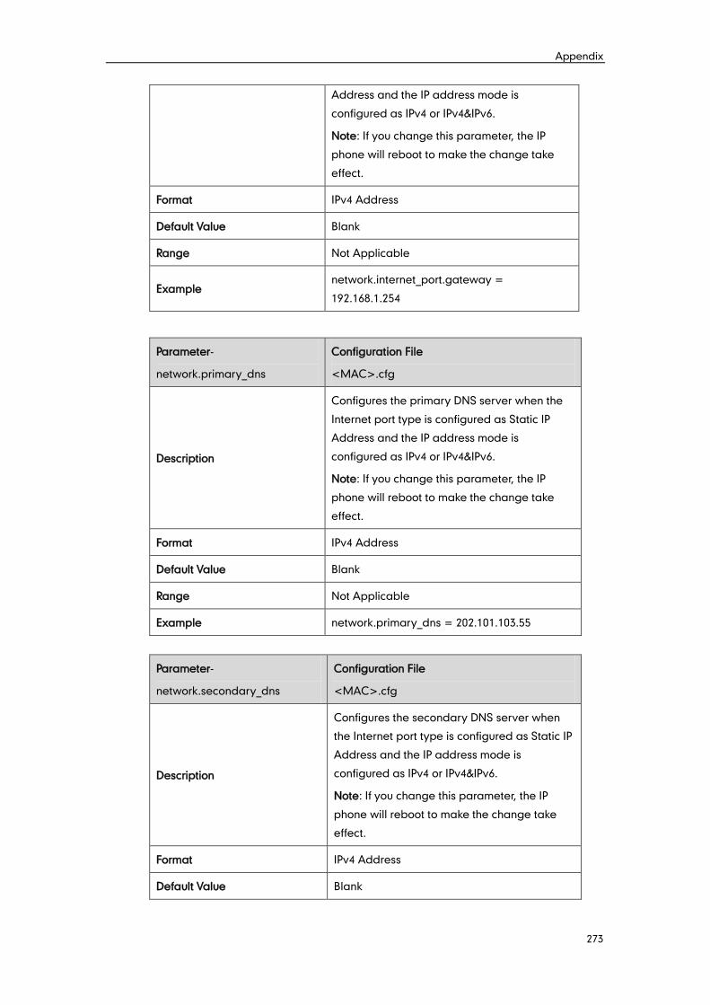
Appendix
273
Address and the IP address mode is
configured as IPv4 or IPv4&IPv6.
Note: If you change this parameter, the IP
phone will reboot to make the change take
effect.
Format IPv4 Address
Default Value Blank
Range Not Applicable
Example network.internet_port.gateway =
192.168.1.254
Parameter-
network.primary_dns
Configuration File
<MAC>.cfg
Description
Configures the primary DNS server when the
Internet port type is configured as Static IP
Address and the IP address mode is
configured as IPv4 or IPv4&IPv6.
Note: If you change this parameter, the IP
phone will reboot to make the change take
effect.
Format IPv4 Address
Default Value Blank
Range Not Applicable
Example network.primary_dns = 202.101.103.55
Parameter-
network.secondary_dns
Configuration File
<MAC>.cfg
Description
Configures the secondary DNS server when
the Internet port type is configured as Static IP
Address and the IP address mode is
configured as IPv4 or IPv4&IPv6.
Note: If you change this parameter, the IP
phone will reboot to make the change take
effect.
Format IPv4 Address
Default Value Blank
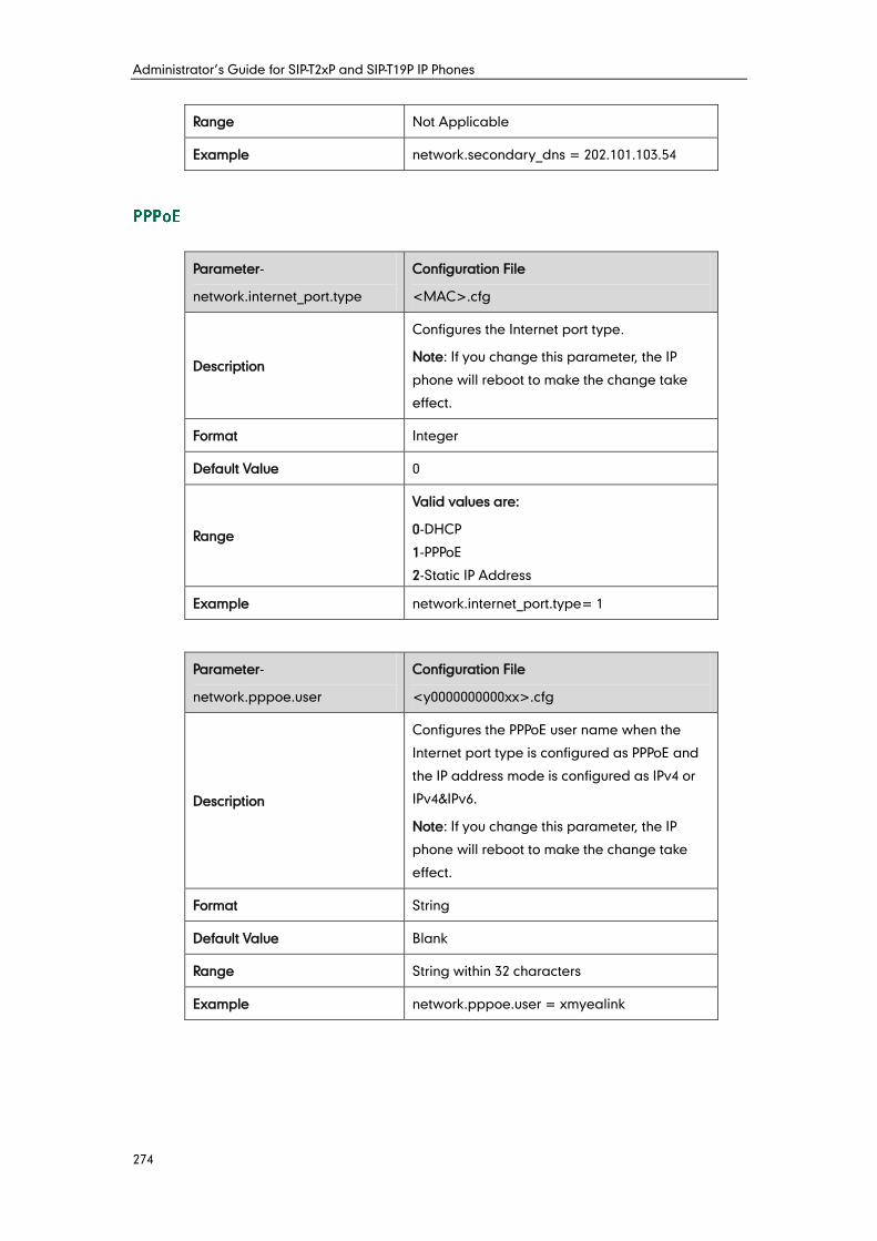
Administrator’s Guide for SIP-T2xP and SIP-T19P IP Phones
274
Range Not Applicable
Example network.secondary_dns = 202.101.103.54
Parameter-
network.internet_port.type
Configuration File
<MAC>.cfg
Description
Configures the Internet port type.
Note: If you change this parameter, the IP
phone will reboot to make the change take
effect.
Format Integer
Default Value 0
Range
Valid values are:
0-DHCP
1-PPPoE
2-Static IP Address
Example network.internet_port.type= 1
Parameter-
network.pppoe.user
Configuration File
<y0000000000xx>.cfg
Description
Configures the PPPoE user name when the
Internet port type is configured as PPPoE and
the IP address mode is configured as IPv4 or
IPv4&IPv6.
Note: If you change this parameter, the IP
phone will reboot to make the change take
effect.
Format String
Default Value Blank
Range String within 32 characters
Example network.pppoe.user = xmyealink
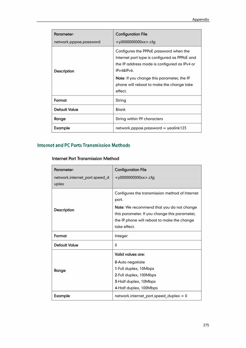
Appendix
275
Parameter-
network.pppoe.password
Configuration File
<y0000000000xx>.cfg
Description
Configures the PPPoE password when the
Internet port type is configured as PPPoE and
the IP address mode is configured as IPv4 or
IPv4&IPv6.
Note: If you change this parameter, the IP
phone will reboot to make the change take
effect.
Format String
Default Value Blank
Range String within 99 characters
Example network.pppoe.password = yealink123
Internet Port Transmission Method
Parameter-
network.internet_port.speed_d
uplex
Configuration File
<y0000000000xx>.cfg
Description
Configures the transmission method of Internet
port.
Note: We recommend that you do not change
this parameter. If you change this parameter,
the IP phone will reboot to make the change
take effect.
Format Integer
Default Value 0
Range
Valid values are:
0-Auto negotiate
1-Full duplex, 10Mbps
2-Full duplex, 100Mbps
3-Half duplex, 10Mbps
4-Half duplex, 100Mbps
Example network.internet_port.speed_duplex = 0
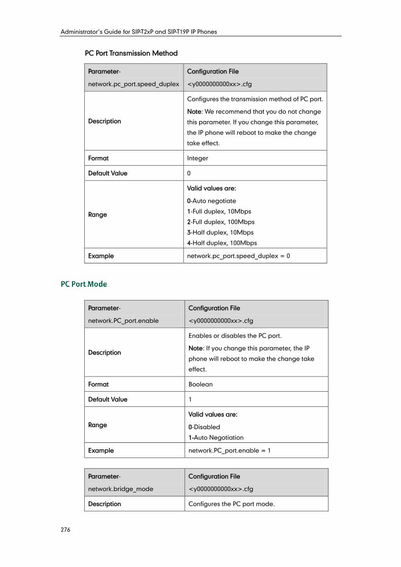
Administrator’s Guide for SIP-T2xP and SIP-T19P IP Phones
276
PC Port Transmission Method
Parameter-
network.pc_port.speed_duplex
Configuration File
<y0000000000xx>.cfg
Description
Configures the transmission method of PC port.
Note: We recommend that you do not change
this parameter. If you change this parameter,
the IP phone will reboot to make the change
take effect.
Format Integer
Default Value 0
Range
Valid values are:
0-Auto negotiate
1-Full duplex, 10Mbps
2-Full duplex, 100Mbps
3-Half duplex, 10Mbps
4-Half duplex, 100Mbps
Example network.pc_port.speed_duplex = 0
Parameter-
network.PC_port.enable
Configuration File
<y0000000000xx>.cfg
Description
Enables or disables the PC port.
Note: If you change this parameter, the IP
phone will reboot to make the change take
effect.
Format Boolean
Default Value 1
Range
Valid values are:
0-Disabled
1-Auto Negotiation
Example network.PC_port.enable = 1
Parameter-
network.bridge_mode
Configuration File
<y0000000000xx>.cfg
Description Configures the PC port mode.
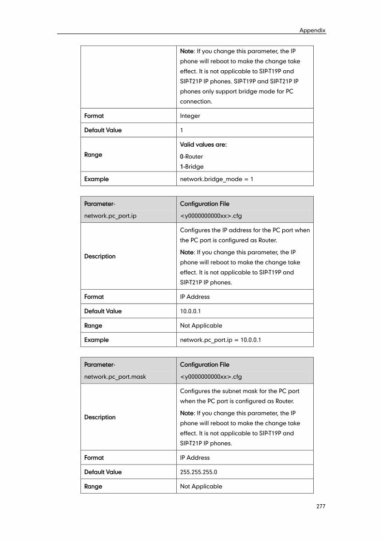
Appendix
277
Note: If you change this parameter, the IP
phone will reboot to make the change take
effect. It is not applicable to SIP-T19P and
SIP-T21P IP phones. SIP-T19P and SIP-T21P IP
phones only support bridge mode for PC
connection.
Format Integer
Default Value 1
Range
Valid values are:
0-Router
1-Bridge
Example network.bridge_mode = 1
Parameter-
network.pc_port.ip
Configuration File
<y0000000000xx>.cfg
Description
Configures the IP address for the PC port when
the PC port is configured as Router.
Note: If you change this parameter, the IP
phone will reboot to make the change take
effect. It is not applicable to SIP-T19P and
SIP-T21P IP phones.
Format IP Address
Default Value 10.0.0.1
Range Not Applicable
Example network.pc_port.ip = 10.0.0.1
Parameter-
network.pc_port.mask
Configuration File
<y0000000000xx>.cfg
Description
Configures the subnet mask for the PC port
when the PC port is configured as Router.
Note: If you change this parameter, the IP
phone will reboot to make the change take
effect. It is not applicable to SIP-T19P and
SIP-T21P IP phones.
Format IP Address
Default Value 255.255.255.0
Range Not Applicable
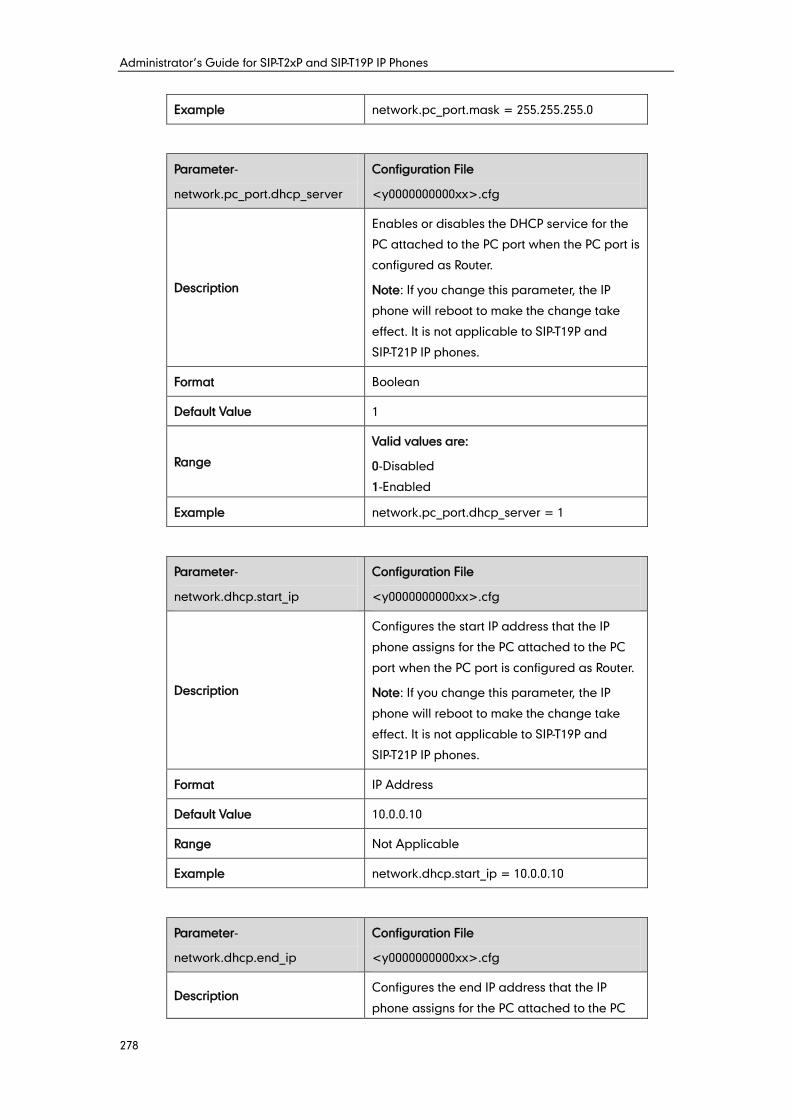
Administrator’s Guide for SIP-T2xP and SIP-T19P IP Phones
278
Example network.pc_port.mask = 255.255.255.0
Parameter-
network.pc_port.dhcp_server
Configuration File
<y0000000000xx>.cfg
Description
Enables or disables the DHCP service for the
PC attached to the PC port when the PC port is
configured as Router.
Note: If you change this parameter, the IP
phone will reboot to make the change take
effect. It is not applicable to SIP-T19P and
SIP-T21P IP phones.
Format Boolean
Default Value 1
Range
Valid values are:
0-Disabled
1-Enabled
Example network.pc_port.dhcp_server = 1
Parameter-
network.dhcp.start_ip
Configuration File
<y0000000000xx>.cfg
Description
Configures the start IP address that the IP
phone assigns for the PC attached to the PC
port when the PC port is configured as Router.
Note: If you change this parameter, the IP
phone will reboot to make the change take
effect. It is not applicable to SIP-T19P and
SIP-T21P IP phones.
Format IP Address
Default Value 10.0.0.10
Range Not Applicable
Example network.dhcp.start_ip = 10.0.0.10
Parameter-
network.dhcp.end_ip
Configuration File
<y0000000000xx>.cfg
Description Configures the end IP address that the IP
phone assigns for the PC attached to the PC
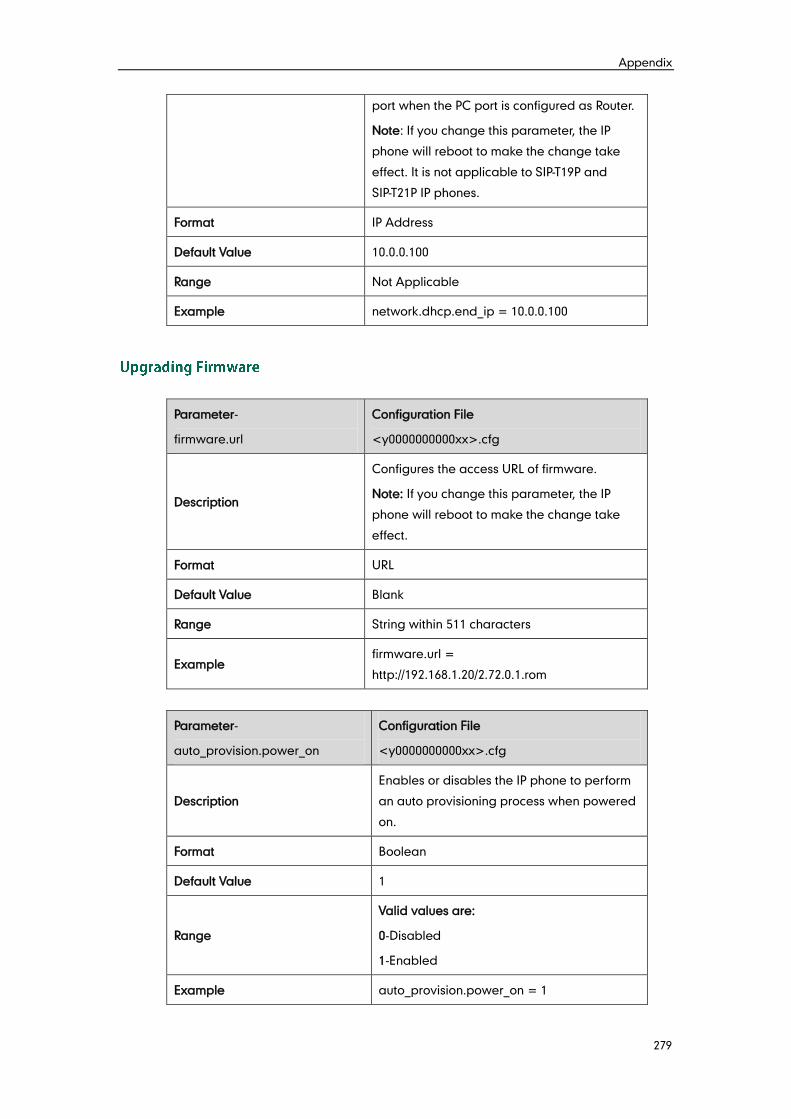
Appendix
279
port when the PC port is configured as Router.
Note: If you change this parameter, the IP
phone will reboot to make the change take
effect. It is not applicable to SIP-T19P and
SIP-T21P IP phones.
Format IP Address
Default Value 10.0.0.100
Range Not Applicable
Example network.dhcp.end_ip = 10.0.0.100
Parameter-
firmware.url
Configuration File
<y0000000000xx>.cfg
Description
Configures the access URL of firmware.
Note: If you change this parameter, the IP
phone will reboot to make the change take
effect.
Format URL
Default Value Blank
Range String within 511 characters
Example firmware.url =
http://192.168.1.20/2.72.0.1.rom
Parameter-
auto_provision.power_on
Configuration File
<y0000000000xx>.cfg
Description
Enables or disables the IP phone to perform
an auto provisioning process when powered
on.
Format Boolean
Default Value 1
Range
Valid values are:
0-Disabled
1-Enabled
Example auto_provision.power_on = 1
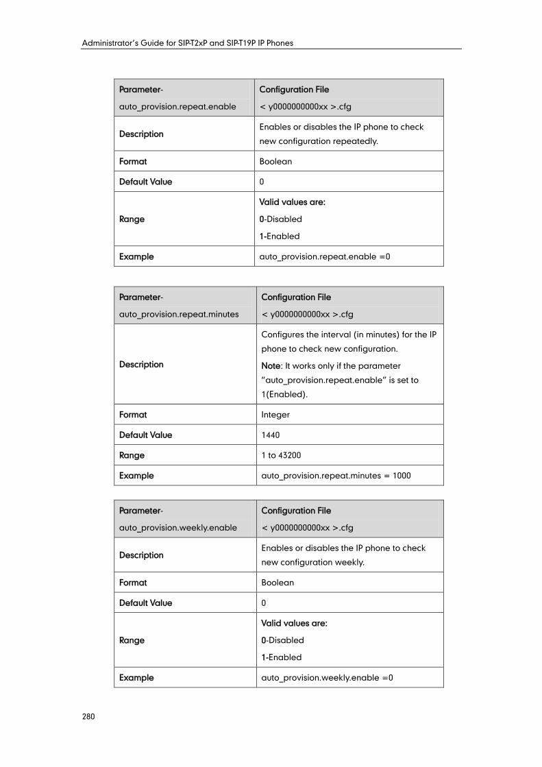
Administrator’s Guide for SIP-T2xP and SIP-T19P IP Phones
280
Parameter-
auto_provision.repeat.enable
Configuration File
< y0000000000xx >.cfg
Description Enables or disables the IP phone to check
new configuration repeatedly.
Format Boolean
Default Value 0
Range
Valid values are:
0-Disabled
1-Enabled
Example auto_provision.repeat.enable =0
Parameter-
auto_provision.repeat.minutes
Configuration File
< y0000000000xx >.cfg
Description
Configures the interval (in minutes) for the IP
phone to check new configuration.
Note: It works only if the parameter
“auto_provision.repeat.enable” is set to
1(Enabled).
Format Integer
Default Value 1440
Range 1 to 43200
Example auto_provision.repeat.minutes = 1000
Parameter-
auto_provision.weekly.enable
Configuration File
< y0000000000xx >.cfg
Description Enables or disables the IP phone to check
new configuration weekly.
Format Boolean
Default Value 0
Range
Valid values are:
0-Disabled
1-Enabled
Example auto_provision.weekly.enable =0
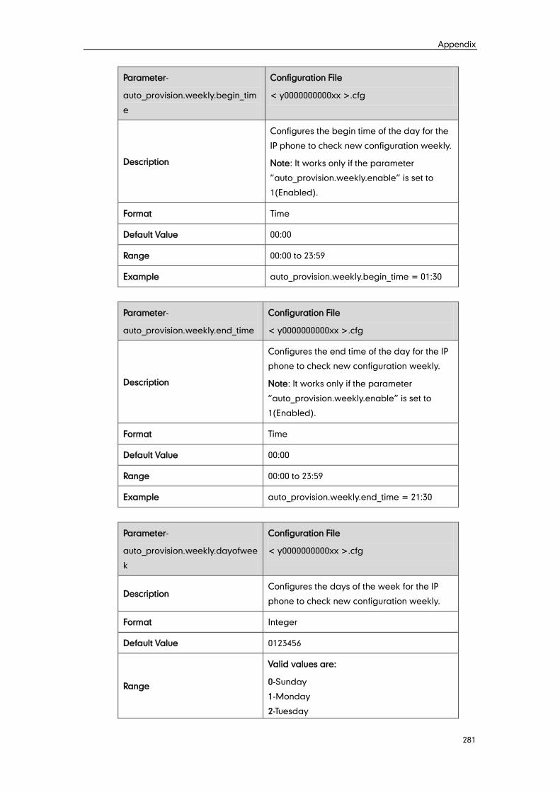
Appendix
281
Parameter-
auto_provision.weekly.begin_tim
e
Configuration File
< y0000000000xx >.cfg
Description
Configures the begin time of the day for the
IP phone to check new configuration weekly.
Note: It works only if the parameter
“auto_provision.weekly.enable” is set to
1(Enabled).
Format Time
Default Value 00:00
Range 00:00 to 23:59
Example auto_provision.weekly.begin_time = 01:30
Parameter-
auto_provision.weekly.end_time
Configuration File
< y0000000000xx >.cfg
Description
Configures the end time of the day for the IP
phone to check new configuration weekly.
Note: It works only if the parameter
“auto_provision.weekly.enable” is set to
1(Enabled).
Format Time
Default Value 00:00
Range 00:00 to 23:59
Example auto_provision.weekly.end_time = 21:30
Parameter-
auto_provision.weekly.dayofwee
k
Configuration File
< y0000000000xx >.cfg
Description Configures the days of the week for the IP
phone to check new configuration weekly.
Format Integer
Default Value 0123456
Range
Valid values are:
0-Sunday
1-Monday
2-Tuesday
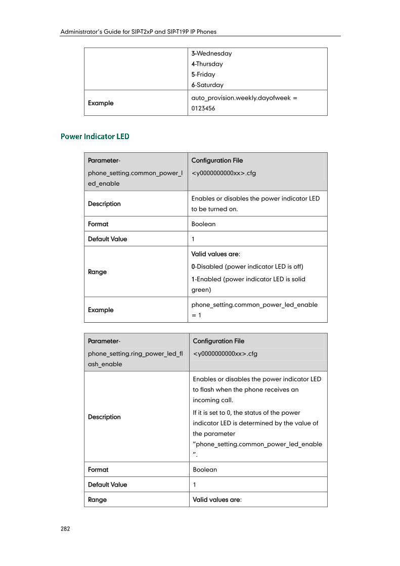
Administrator’s Guide for SIP-T2xP and SIP-T19P IP Phones
282
3-Wednesday
4-Thursday
5-Friday
6-Saturday
Example auto_provision.weekly.dayofweek =
0123456
Parameter-
phone_setting.common_power_l
ed_enable
Configuration File
<y0000000000xx>.cfg
Description Enables or disables the power indicator LED
to be turned on.
Format Boolean
Default Value 1
Range
Valid values are:
0-Disabled (power indicator LED is off)
1-Enabled (power indicator LED is solid
green)
Example phone_setting.common_power_led_enable
= 1
Parameter-
phone_setting.ring_power_led_fl
ash_enable
Configuration File
<y0000000000xx>.cfg
Description
Enables or disables the power indicator LED
to flash when the phone receives an
incoming call.
If it is set to 0, the status of the power
indicator LED is determined by the value of
the parameter
“phone_setting.common_power_led_enable
”.
Format Boolean
Default Value 1
Range Valid values are:
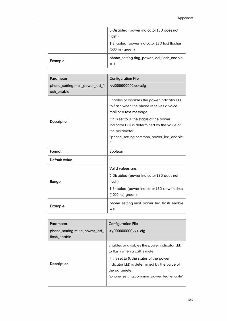
Appendix
283
0-Disabled (power indicator LED does not
flash)
1-Enabled (power indicator LED fast flashes
(300ms) green)
Example phone_setting.ring_power_led_flash_enable
= 1
Parameter-
phone_setting.mail_power_led_fl
ash_enable
Configuration File
<y0000000000xx>.cfg
Description
Enables or disables the power indicator LED
to flash when the phone receives a voice
mail or a text message.
If it is set to 0, the status of the power
indicator LED is determined by the value of
the parameter
“phone_setting.common_power_led_enable
”.
Format Boolean
Default Value 0
Range
Valid values are:
0-Disabled (power indicator LED does not
flash)
1-Enabled (power indicator LED slow flashes
(1000ms) green)
Example phone_setting.mail_power_led_flash_enable
= 0
Parameter-
phone_setting.mute_power_led_
flash_enable
Configuration File
<y0000000000xx>.cfg
Description
Enables or disables the power indicator LED
to flash when a call is mute.
If it is set to 0, the status of the power
indicator LED is determined by the value of
the parameter
“phone_setting.common_power_led_enable”
.

Administrator’s Guide for SIP-T2xP and SIP-T19P IP Phones
284
Format Boolean
Default Value 1
Range
Valid values are:
0-Disabled (power indicator LED does not
flash)
1-Enabled (power indicator LED fast flashes
(300ms) green)
Example phone_setting.mute_power_led_flash_enabl
e = 1
Parameter-
phone_setting.hold_and_held_p
ower_led_flash_enable
Configuration File
<y0000000000xx>.cfg
Description
Enables or disables the power indicator LED
to flash when a call is placed on hold or is
held.
If it is set to 0, the status of the power
indicator LED is determined by the value of
the parameter
“phone_setting.common_power_led_enable”
.
Format Boolean
Default Value 0
Range
Valid values are:
0-Disabled (power indicator LED does not
flash)
1-Enabled (power indicator LED fast flashes
(500ms) green)
Example phone_setting.hold_and_held_power_led_fla
sh_enable = 0
Parameter-
phone_setting.talk_and_dial_po
wer_led_enable
Configuration File
<y0000000000xx>.cfg
Description
Enables or disables the power indicator LED
to be turned on when the phone is busy.
If it is set to 0, the status of the power
indicator LED is determined by the value of
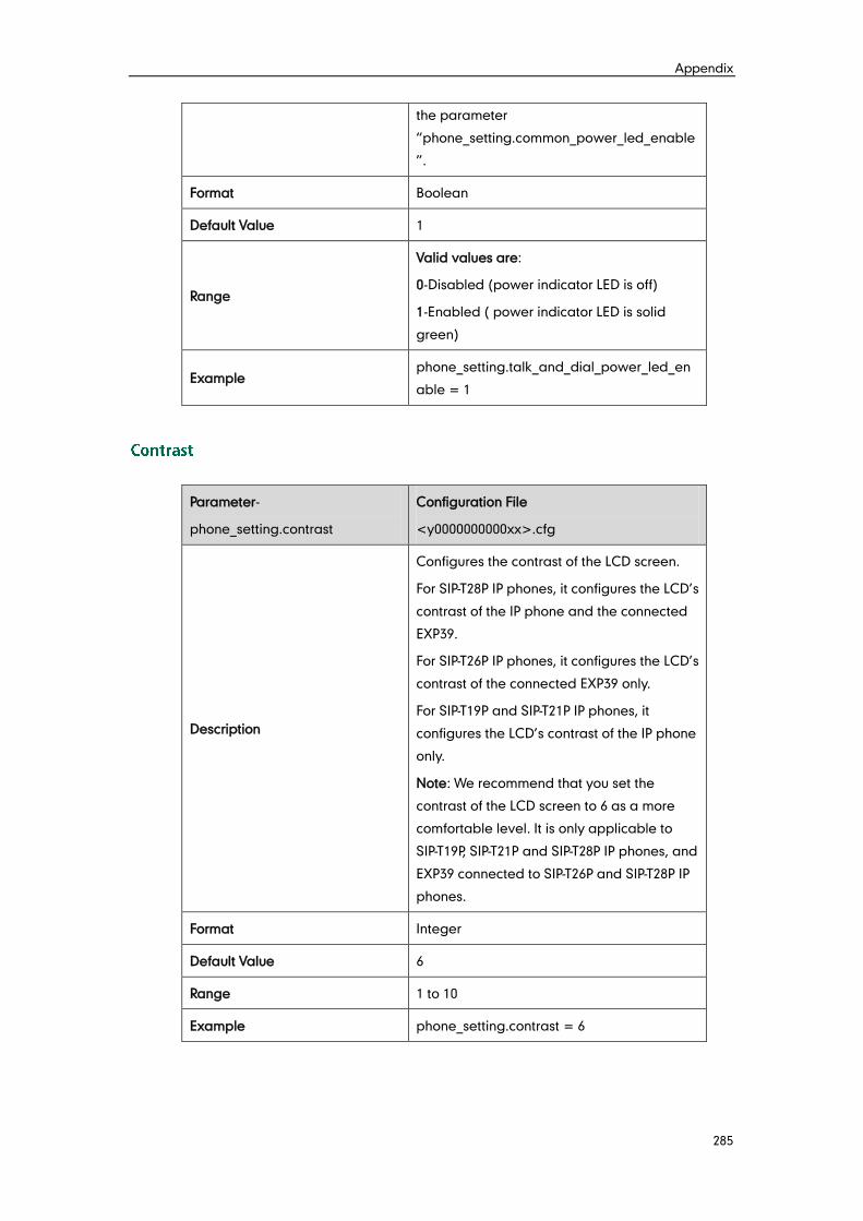
Appendix
285
the parameter
“phone_setting.common_power_led_enable
”.
Format Boolean
Default Value 1
Range
Valid values are:
0-Disabled (power indicator LED is off)
1-Enabled ( power indicator LED is solid
green)
Example phone_setting.talk_and_dial_power_led_en
able = 1
Parameter-
phone_setting.contrast
Configuration File
<y0000000000xx>.cfg
Description
Configures the contrast of the LCD screen.
For SIP-T28P IP phones, it configures the LCD’s
contrast of the IP phone and the connected
EXP39.
For SIP-T26P IP phones, it configures the LCD’s
contrast of the connected EXP39 only.
For SIP-T19P and SIP-T21P IP phones, it
configures the LCD’s contrast of the IP phone
only.
Note: We recommend that you set the
contrast of the LCD screen to 6 as a more
comfortable level. It is only applicable to
SIP-T19P, SIP-T21P and SIP-T28P IP phones, and
EXP39 connected to SIP-T26P and SIP-T28P IP
phones.
Format Integer
Default Value 6
Range 1 to 10
Example phone_setting.contrast = 6
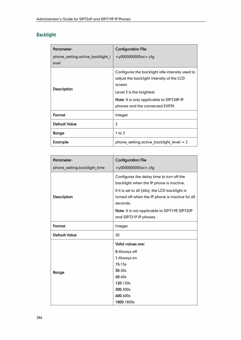
Administrator’s Guide for SIP-T2xP and SIP-T19P IP Phones
286
Parameter-
phone_setting.active_backlight_l
evel
Configuration File
<y0000000000xx>.cfg
Description
Configures the backlight idle intensity used to
adjust the backlight intensity of the LCD
screen
Level 3 is the brightest.
Note: It is only applicable to SIP-T28P IP
phones and the connected EXP39.
Format Integer
Default Value 2
Range 1 to 3
Example phone_setting.active_backlight_level = 2
Parameter-
phone_setting.backlight_time
Configuration File
<y0000000000xx>.cfg
Description
Configures the delay time to turn off the
backlight when the IP phone is inactive.
If it is set to 60 (60s), the LCD backlight is
turned off when the IP phone is inactive for 60
seconds.
Note: It is not applicable to SIP-T19P, SIP-T20P
and SIP-T21P IP phones.
Format Integer
Default Value 30
Range
Valid values are:
0-Always off
1-Always on
15-15s
30-30s
60-60s
120-120s
300-300s
600-600s
1800-1800s
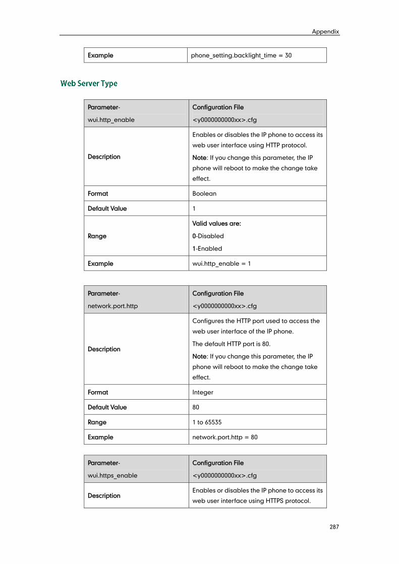
Appendix
287
Example phone_setting.backlight_time = 30
Parameter-
wui.http_enable
Configuration File
<y0000000000xx>.cfg
Description
Enables or disables the IP phone to access its
web user interface using HTTP protocol.
Note: If you change this parameter, the IP
phone will reboot to make the change take
effect.
Format Boolean
Default Value 1
Range
Valid values are:
0-Disabled
1-Enabled
Example wui.http_enable = 1
Parameter-
network.port.http
Configuration File
<y0000000000xx>.cfg
Description
Configures the HTTP port used to access the
web user interface of the IP phone.
The default HTTP port is 80.
Note: If you change this parameter, the IP
phone will reboot to make the change take
effect.
Format Integer
Default Value 80
Range 1 to 65535
Example network.port.http = 80
Parameter-
wui.https_enable
Configuration File
<y0000000000xx>.cfg
Description Enables or disables the IP phone to access its
web user interface using HTTPS protocol.
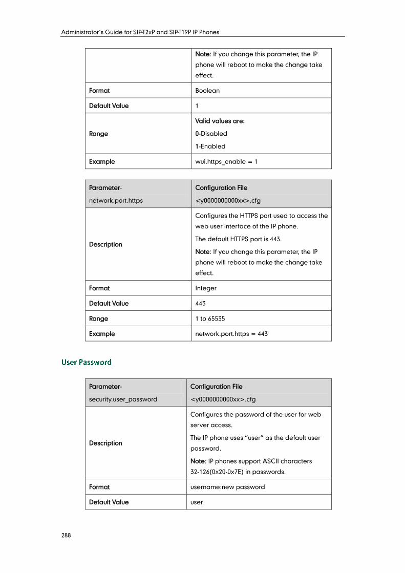
Administrator’s Guide for SIP-T2xP and SIP-T19P IP Phones
288
Note: If you change this parameter, the IP
phone will reboot to make the change take
effect.
Format Boolean
Default Value 1
Range
Valid values are:
0-Disabled
1-Enabled
Example wui.https_enable = 1
Parameter-
network.port.https
Configuration File
<y0000000000xx>.cfg
Description
Configures the HTTPS port used to access the
web user interface of the IP phone.
The default HTTPS port is 443.
Note: If you change this parameter, the IP
phone will reboot to make the change take
effect.
Format Integer
Default Value 443
Range 1 to 65535
Example network.port.https = 443
Parameter-
security.user_password
Configuration File
<y0000000000xx>.cfg
Description
Configures the password of the user for web
server access.
The IP phone uses “user” as the default user
password.
Note: IP phones support ASCII characters
32-126(0x20-0x7E) in passwords.
Format username:new password
Default Value user

Appendix
289
Range String within 32 characters
Example security.user_password = user:password123
Parameter-
security.user_password
Configuration File
<y0000000000xx>.cfg
Description
Configures the password of the administrator
for web server access.
The IP phone uses “admin” as the default
administrator password.
Note: IP phones support ASCII characters
32-126(0x20-0x7E) in passwords.
Format administrator username:new password
Default Value admin
Range String within 32 characters
Example security.user_password = admin:password000
Parameter-
phone_setting.lock
Configuration File
<y0000000000xx>.cfg
Description
Configures the type of phone lock.
Menu Key: The Menu soft key and MESSAGE
key are locked (For SIP-T20P, the MENU key is
locked).
Function Keys: MESSAGE, RD, CONF, HOLD,
MUTE, TRAN, OK, X, navigation keys, soft keys,
line keys and memory keys are locked (For
SIP-T22P/T21P, CONF, HOLD, MUTE and
memory keys do not exist; For SIP-T20P, the
MUTE key, soft keys and memory keys do not
exist, but the additional MENU and Directory
keys are locked; For SIP-T19P, CONF, HOLD, OK,
X, memory keys and line keys do not exist, but
the additional √ key is locked).
All Keys: All keys are locked except the volume
key. You are only allowed to dial emergency

Administrator’s Guide for SIP-T2xP and SIP-T19P IP Phones
290
numbers, reject incoming calls by pressing the
X key, answer incoming calls by lifting the
handset, pressing the Speakerphone key, the
HEADSET key or the OK key, place an active
call on hold by pressing the Hold soft key or
the HOLD key, resume the held call by
pressing the Resume soft key or the HOLD key,
and end the call by hanging up the handset,
pressing the Speakerphone key or pressing
the X key (pressing the X key to end the call is
not applicable to SIP-T22P/T21P/T20P). For
SIP-T22P/T21P, HOLD key does not exist; For
SIP-T20P, soft keys do not exist. For SIP-T19P,
HOLD and X keys do not exist.
If it is set to 0 (Disabled), IP phone lock feature
is disabled.
Format Integer
Default Value 0
Range
Valid values are:
0-Disabled
1-Menu Key
2-Function Keys
3-All Keys
Example phone_setting.lock = 1
Parameter-
phone_setting.phone_lock.unlo
ck_pin
Configuration File
<y0000000000xx>.cfg
Description
Configures a new unlock PIN. Once the IP
phone is locked, you can use the default
password “123” to unlock it.
Format numeric characters
Default Value 123
Range characters within 15 digits
Example phone_setting.phone_lock.unlock_pin = 123
Parameter-
phone_setting.phone_lock.lock
Configuration File
<y0000000000xx>.cfg
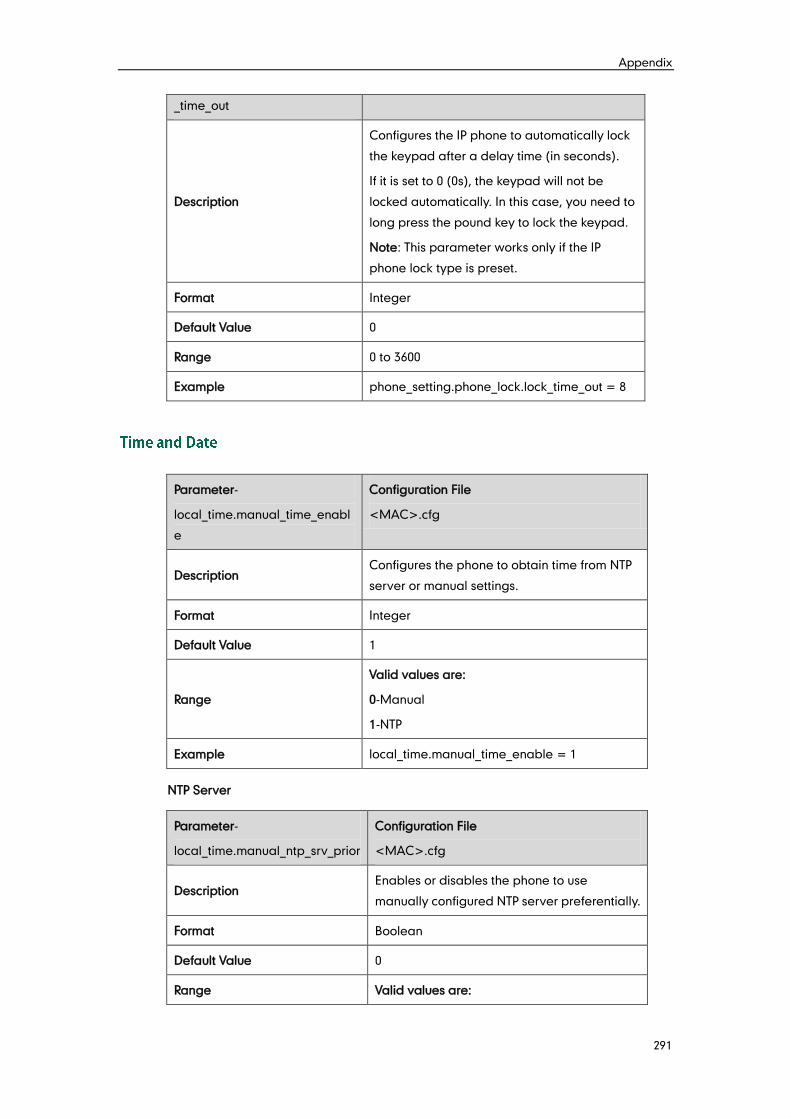
Appendix
291
_time_out
Description
Configures the IP phone to automatically lock
the keypad after a delay time (in seconds).
If it is set to 0 (0s), the keypad will not be
locked automatically. In this case, you need to
long press the pound key to lock the keypad.
Note: This parameter works only if the IP
phone lock type is preset.
Format Integer
Default Value 0
Range 0 to 3600
Example phone_setting.phone_lock.lock_time_out = 8
Parameter-
local_time.manual_time_enabl
e
Configuration File
<MAC>.cfg
Description Configures the phone to obtain time from NTP
server or manual settings.
Format Integer
Default Value 1
Range
Valid values are:
0-Manual
1-NTP
Example local_time.manual_time_enable = 1
NTP Server
Parameter-
local_time.manual_ntp_srv_prior
Configuration File
<MAC>.cfg
Description Enables or disables the phone to use
manually configured NTP server preferentially.
Format Boolean
Default Value 0
Range Valid values are:
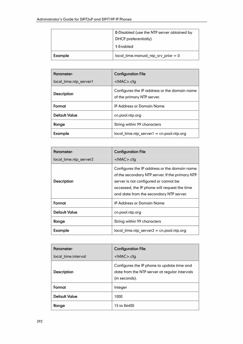
Administrator’s Guide for SIP-T2xP and SIP-T19P IP Phones
292
0-Disabled (use the NTP server obtained by
DHCP preferentially)
1-Enabled
Example local_time.manual_ntp_srv_prior = 0
Parameter-
local_time.ntp_server1
Configuration File
<MAC>.cfg
Description Configures the IP address or the domain name
of the primary NTP server.
Format IP Address or Domain Name
Default Value cn.pool.ntp.org
Range String within 99 characters
Example local_time.ntp_server1 = cn.pool.ntp.org
Parameter-
local_time.ntp_server2
Configuration File
<MAC>.cfg
Description
Configures the IP address or the domain name
of the secondary NTP server. If the primary NTP
server is not configured or cannot be
accessed, the IP phone will request the time
and date from the secondary NTP server.
Format IP Address or Domain Name
Default Value cn.pool.ntp.org
Range String within 99 characters
Example local_time.ntp_server2 = cn.pool.ntp.org
Parameter-
local_time.interval
Configuration File
<MAC>.cfg
Description
Configures the IP phone to update time and
date from the NTP server at regular intervals
(in seconds).
Format Integer
Default Value 1000
Range 15 to 86400
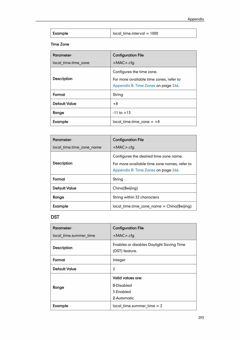
Appendix
293
Example local_time.interval = 1000
Time Zone
Parameter-
local_time.time_zone
Configuration File
<MAC>.cfg
Description
Configures the time zone.
For more available time zones, refer to
Appendix B: Time Zones on page 266.
Format String
Default Value +8
Range -11 to +13
Example local_time.time_zone = +8
Parameter-
local_time.time_zone_name
Configuration File
<MAC>.cfg
Description
Configures the desired time zone name.
For more available time zone names, refer to
Appendix B: Time Zones on page 266.
Format String
Default Value China(Beijing)
Range String within 32 characters
Example local_time.time_zone_name = China(Beijing)
DST
Parameter-
local_time.summer_time
Configuration File
<MAC>.cfg
Description Enables or disables Daylight Saving Time
(DST) feature.
Format Integer
Default Value 2
Range
Valid values are:
0-Disabled
1-Enabled
2-Automatic
Example local_time.summer_time = 2
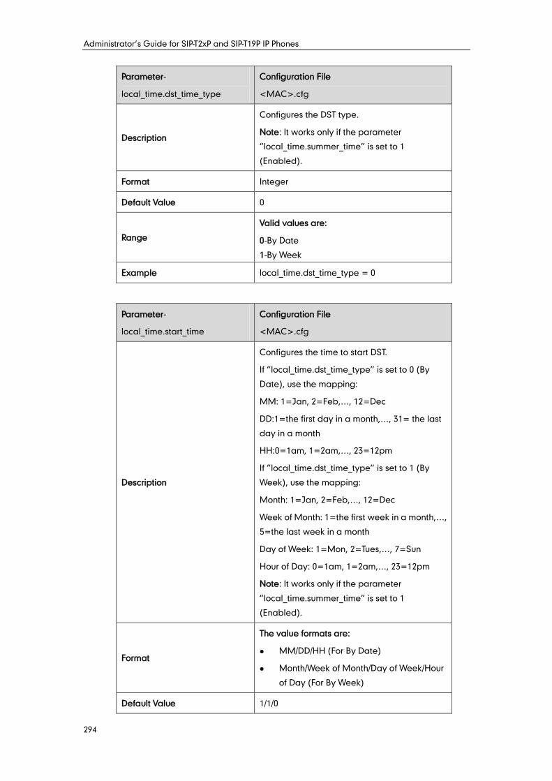
Administrator’s Guide for SIP-T2xP and SIP-T19P IP Phones
294
Parameter-
local_time.dst_time_type
Configuration File
<MAC>.cfg
Description
Configures the DST type.
Note: It works only if the parameter
“local_time.summer_time” is set to 1
(Enabled).
Format Integer
Default Value 0
Range
Valid values are:
0-By Date
1-By Week
Example local_time.dst_time_type = 0
Parameter-
local_time.start_time
Configuration File
<MAC>.cfg
Description
Configures the time to start DST.
If “local_time.dst_time_type” is set to 0 (By
Date), use the mapping:
MM: 1=Jan, 2=Feb,…, 12=Dec
DD:1=the first day in a month,…, 31= the last
day in a month
HH:0=1am, 1=2am,…, 23=12pm
If “local_time.dst_time_type” is set to 1 (By
Week), use the mapping:
Month: 1=Jan, 2=Feb,…, 12=Dec
Week of Month: 1=the first week in a month,…,
5=the last week in a month
Day of Week: 1=Mon, 2=Tues,…, 7=Sun
Hour of Day: 0=1am, 1=2am,…, 23=12pm
Note: It works only if the parameter
“local_time.summer_time” is set to 1
(Enabled).
Format
The value formats are:
MM/DD/HH (For By Date)
Month/Week of Month/Day of Week/Hour
of Day (For By Week)
Default Value 1/1/0
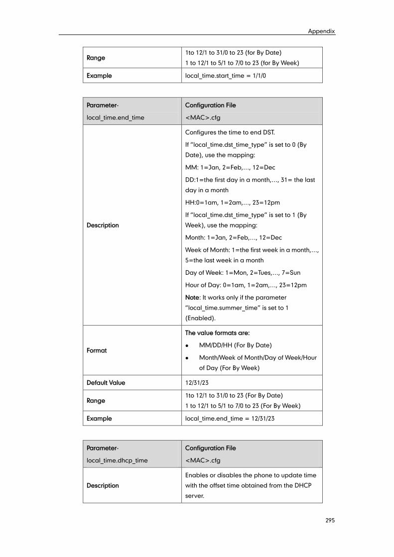
Appendix
295
Range 1to 12/1 to 31/0 to 23 (for By Date)
1 to 12/1 to 5/1 to 7/0 to 23 (for By Week)
Example local_time.start_time = 1/1/0
Parameter-
local_time.end_time
Configuration File
<MAC>.cfg
Description
Configures the time to end DST.
If “local_time.dst_time_type” is set to 0 (By
Date), use the mapping:
MM: 1=Jan, 2=Feb,…, 12=Dec
DD:1=the first day in a month,…, 31= the last
day in a month
HH:0=1am, 1=2am,…, 23=12pm
If “local_time.dst_time_type” is set to 1 (By
Week), use the mapping:
Month: 1=Jan, 2=Feb,…, 12=Dec
Week of Month: 1=the first week in a month,…,
5=the last week in a month
Day of Week: 1=Mon, 2=Tues,…, 7=Sun
Hour of Day: 0=1am, 1=2am,…, 23=12pm
Note: It works only if the parameter
“local_time.summer_time” is set to 1
(Enabled).
Format
The value formats are:
MM/DD/HH (For By Date)
Month/Week of Month/Day of Week/Hour
of Day (For By Week)
Default Value 12/31/23
Range 1to 12/1 to 31/0 to 23 (For By Date)
1 to 12/1 to 5/1 to 7/0 to 23 (For By Week)
Example local_time.end_time = 12/31/23
Parameter-
local_time.dhcp_time
Configuration File
<MAC>.cfg
Description
Enables or disables the phone to update time
with the offset time obtained from the DHCP
server.
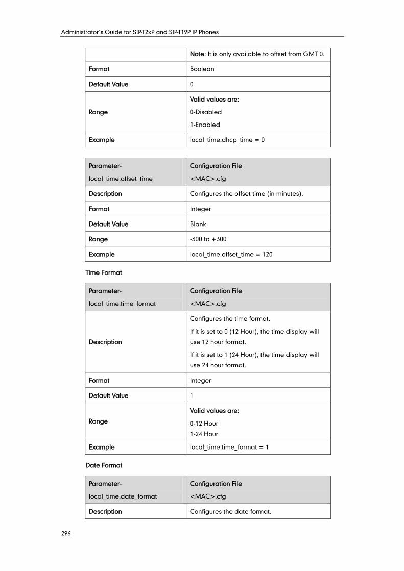
Administrator’s Guide for SIP-T2xP and SIP-T19P IP Phones
296
Note: It is only available to offset from GMT 0.
Format Boolean
Default Value 0
Range
Valid values are:
0-Disabled
1-Enabled
Example local_time.dhcp_time = 0
Parameter-
local_time.offset_time
Configuration File
<MAC>.cfg
Description Configures the offset time (in minutes).
Format Integer
Default Value Blank
Range -300 to +300
Example local_time.offset_time = 120
Time Format
Parameter-
local_time.time_format
Configuration File
<MAC>.cfg
Description
Configures the time format.
If it is set to 0 (12 Hour), the time display will
use 12 hour format.
If it is set to 1 (24 Hour), the time display will
use 24 hour format.
Format Integer
Default Value 1
Range
Valid values are:
0-12 Hour
1-24 Hour
Example local_time.time_format = 1
Date Format
Parameter-
local_time.date_format
Configuration File
<MAC>.cfg
Description Configures the date format.
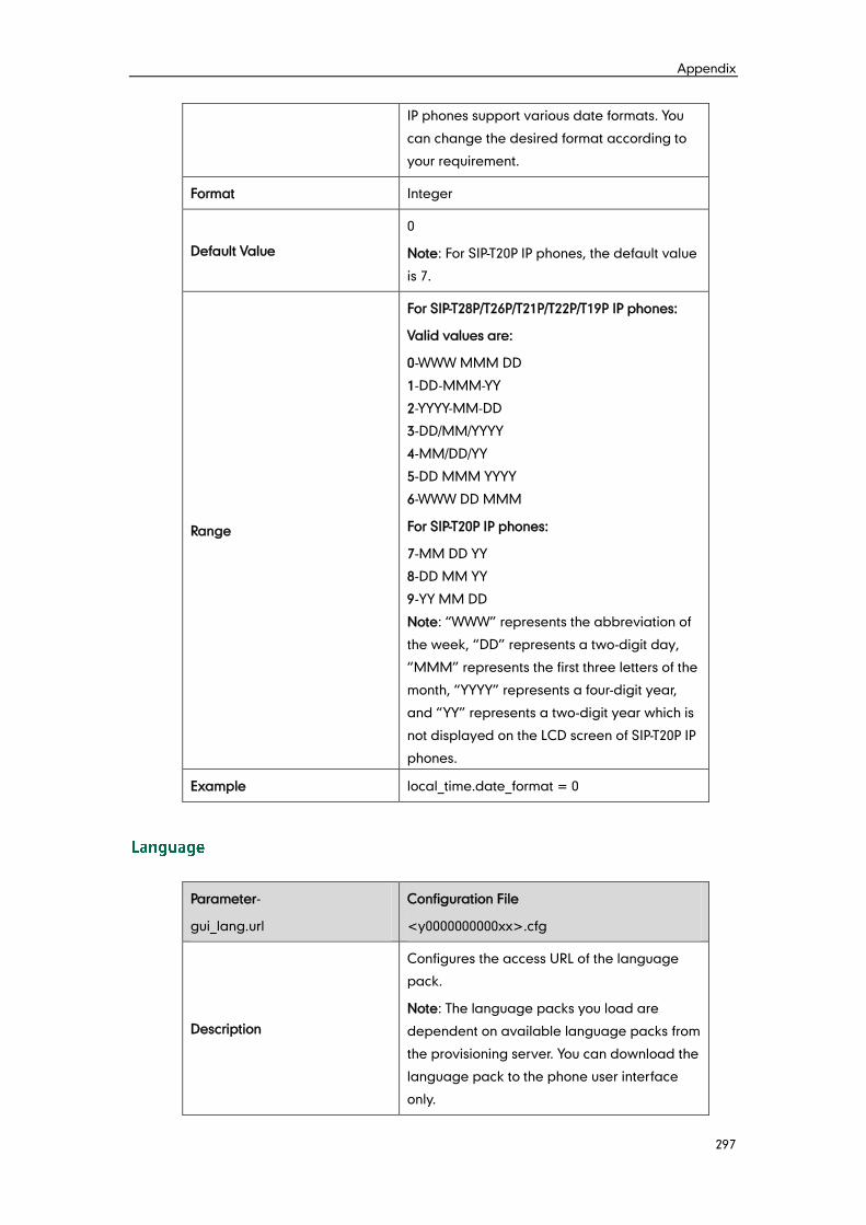
Appendix
297
IP phones support various date formats. You
can change the desired format according to
your requirement.
Format Integer
Default Value
0
Note: For SIP-T20P IP phones, the default value
is 7.
Range
For SIP-T28P/T26P/T21P/T22P/T19P IP phones:
Valid values are:
0-WWW MMM DD
1-DD-MMM-YY
2-YYYY-MM-DD
3-DD/MM/YYYY
4-MM/DD/YY
5-DD MMM YYYY
6-WWW DD MMM
For SIP-T20P IP phones:
7-MM DD YY
8-DD MM YY
9-YY MM DD
Note: “WWW” represents the abbreviation of
the week, “DD” represents a two-digit day,
“MMM” represents the first three letters of the
month, “YYYY” represents a four-digit year,
and “YY” represents a two-digit year which is
not displayed on the LCD screen of SIP-T20P IP
phones.
Example local_time.date_format = 0
Parameter-
gui_lang.url
Configuration File
<y0000000000xx>.cfg
Description
Configures the access URL of the language
pack.
Note: The language packs you load are
dependent on available language packs from
the provisioning server. You can download the
language pack to the phone user interface
only.
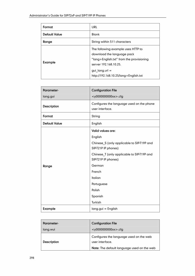
Administrator’s Guide for SIP-T2xP and SIP-T19P IP Phones
298
Format URL
Default Value Blank
Range String within 511 characters
Example
The following example uses HTTP to
download the language pack
“lang+English.txt” from the provisioning
server 192.168.10.25.
gui_lang.url =
http://192.168.10.25/lang+English.txt
Parameter-
lang.gui
Configuration File
<y0000000000xx>.cfg
Description Configures the language used on the phone
user interface.
Format String
Default Value English
Range
Valid values are:
English
Chinese_S (only applicable to SIP-T19P and
SIP-T21P IP phones)
Chinese_T (only applicable to SIP-T19P and
SIP-T21P IP phones)
German
French
Italian
Portuguese
Polish
Spanish
Turkish
Example lang.gui = English
Parameter-
lang.wui
Configuration File
<y0000000000xx>.cfg
Description
Configures the language used on the web
user interface.
Note: The default language used on the web
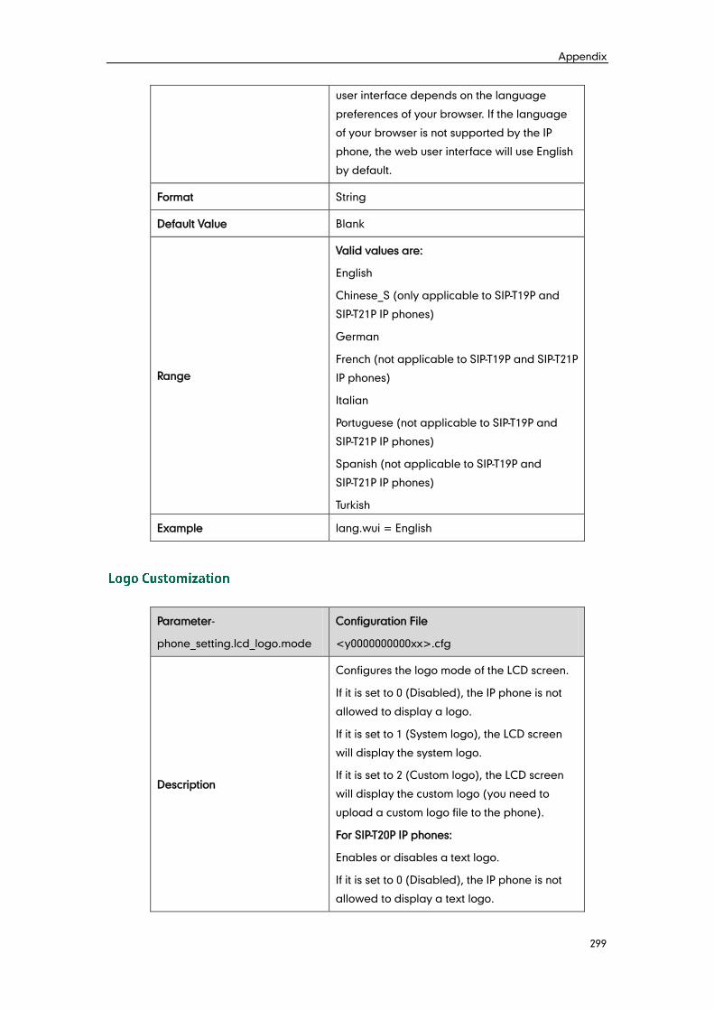
Appendix
299
user interface depends on the language
preferences of your browser. If the language
of your browser is not supported by the IP
phone, the web user interface will use English
by default.
Format String
Default Value Blank
Range
Valid values are:
English
Chinese_S (only applicable to SIP-T19P and
SIP-T21P IP phones)
German
French (not applicable to SIP-T19P and SIP-T21P
IP phones)
Italian
Portuguese (not applicable to SIP-T19P and
SIP-T21P IP phones)
Spanish (not applicable to SIP-T19P and
SIP-T21P IP phones)
Turkish
Example lang.wui = English
Parameter-
phone_setting.lcd_logo.mode
Configuration File
<y0000000000xx>.cfg
Description
Configures the logo mode of the LCD screen.
If it is set to 0 (Disabled), the IP phone is not
allowed to display a logo.
If it is set to 1 (System logo), the LCD screen
will display the system logo.
If it is set to 2 (Custom logo), the LCD screen
will display the custom logo (you need to
upload a custom logo file to the phone).
For SIP-T20P IP phones:
Enables or disables a text logo.
If it is set to 0 (Disabled), the IP phone is not
allowed to display a text logo.
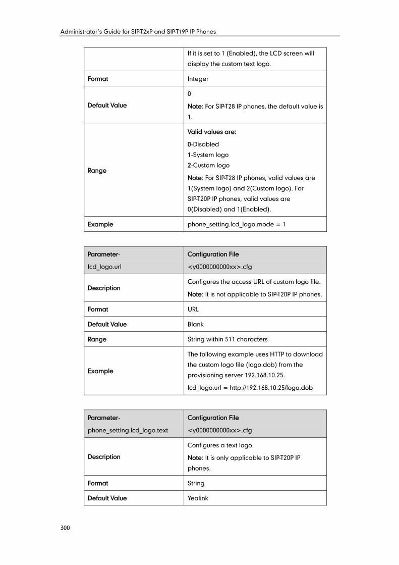
Administrator’s Guide for SIP-T2xP and SIP-T19P IP Phones
300
If it is set to 1 (Enabled), the LCD screen will
display the custom text logo.
Format Integer
Default Value
0
Note: For SIP-T28 IP phones, the default value is
1.
Range
Valid values are:
0-Disabled
1-System logo
2-Custom logo
Note: For SIP-T28 IP phones, valid values are
1(System logo) and 2(Custom logo). For
SIP-T20P IP phones, valid values are
0(Disabled) and 1(Enabled).
Example phone_setting.lcd_logo.mode = 1
Parameter-
lcd_logo.url
Configuration File
<y0000000000xx>.cfg
Description Configures the access URL of custom logo file.
Note: It is not applicable to SIP-T20P IP phones.
Format URL
Default Value Blank
Range String within 511 characters
Example
The following example uses HTTP to download
the custom logo file (logo.dob) from the
provisioning server 192.168.10.25.
lcd_logo.url = http://192.168.10.25/logo.dob
Parameter-
phone_setting.lcd_logo.text
Configuration File
<y0000000000xx>.cfg
Description
Configures a text logo.
Note: It is only applicable to SIP-T20P IP
phones.
Format String
Default Value Yealink
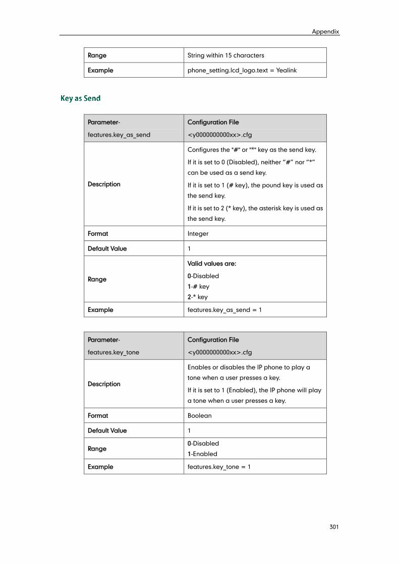
Appendix
301
Range String within 15 characters
Example phone_setting.lcd_logo.text = Yealink
Parameter-
features.key_as_send
Configuration File
<y0000000000xx>.cfg
Description
Configures the "#" or "*" key as the send key.
If it is set to 0 (Disabled), neither “#” nor “*”
can be used as a send key.
If it is set to 1 (# key), the pound key is used as
the send key.
If it is set to 2 (* key), the asterisk key is used as
the send key.
Format Integer
Default Value 1
Range
Valid values are:
0-Disabled
1-# key
2-* key
Example features.key_as_send = 1
Parameter-
features.key_tone
Configuration File
<y0000000000xx>.cfg
Description
Enables or disables the IP phone to play a
tone when a user presses a key.
If it is set to 1 (Enabled), the IP phone will play
a tone when a user presses a key.
Format Boolean
Default Value 1
Range 0-Disabled
1-Enabled
Example features.key_tone = 1
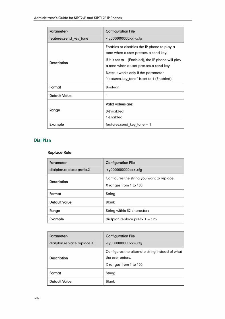
Administrator’s Guide for SIP-T2xP and SIP-T19P IP Phones
302
Parameter-
features.send_key_tone
Configuration File
<y0000000000xx>.cfg
Description
Enables or disables the IP phone to play a
tone when a user presses a send key.
If it is set to 1 (Enabled), the IP phone will play
a tone when a user presses a send key.
Note: It works only if the parameter
“features.key_tone” is set to 1 (Enabled).
Format Boolean
Default Value 1
Range
Valid values are:
0-Disabled
1-Enabled
Example features.send_key_tone = 1
Replace Rule
Parameter-
dialplan.replace.prefix.X
Configuration File
<y0000000000xx>.cfg
Description Configures the string you want to replace.
X ranges from 1 to 100.
Format String
Default Value Blank
Range String within 32 characters
Example dialplan.replace.prefix.1 = 123
Parameter-
dialplan.replace.replace.X
Configuration File
<y0000000000xx>.cfg
Description
Configures the alternate string instead of what
the user enters.
X ranges from 1 to 100.
Format String
Default Value Blank
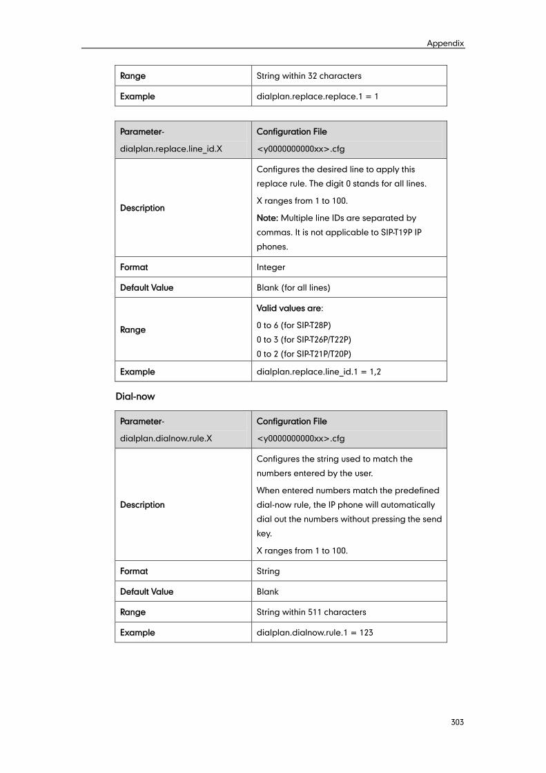
Appendix
303
Range String within 32 characters
Example dialplan.replace.replace.1 = 1
Parameter-
dialplan.replace.line_id.X
Configuration File
<y0000000000xx>.cfg
Description
Configures the desired line to apply this
replace rule. The digit 0 stands for all lines.
X ranges from 1 to 100.
Note: Multiple line IDs are separated by
commas. It is not applicable to SIP-T19P IP
phones.
Format Integer
Default Value Blank (for all lines)
Range
Valid values are:
0 to 6 (for SIP-T28P)
0 to 3 (for SIP-T26P/T22P)
0 to 2 (for SIP-T21P/T20P)
Example dialplan.replace.line_id.1 = 1,2
Dial-now
Parameter-
dialplan.dialnow.rule.X
Configuration File
<y0000000000xx>.cfg
Description
Configures the string used to match the
numbers entered by the user.
When entered numbers match the predefined
dial-now rule, the IP phone will automatically
dial out the numbers without pressing the send
key.
X ranges from 1 to 100.
Format String
Default Value Blank
Range String within 511 characters
Example dialplan.dialnow.rule.1 = 123
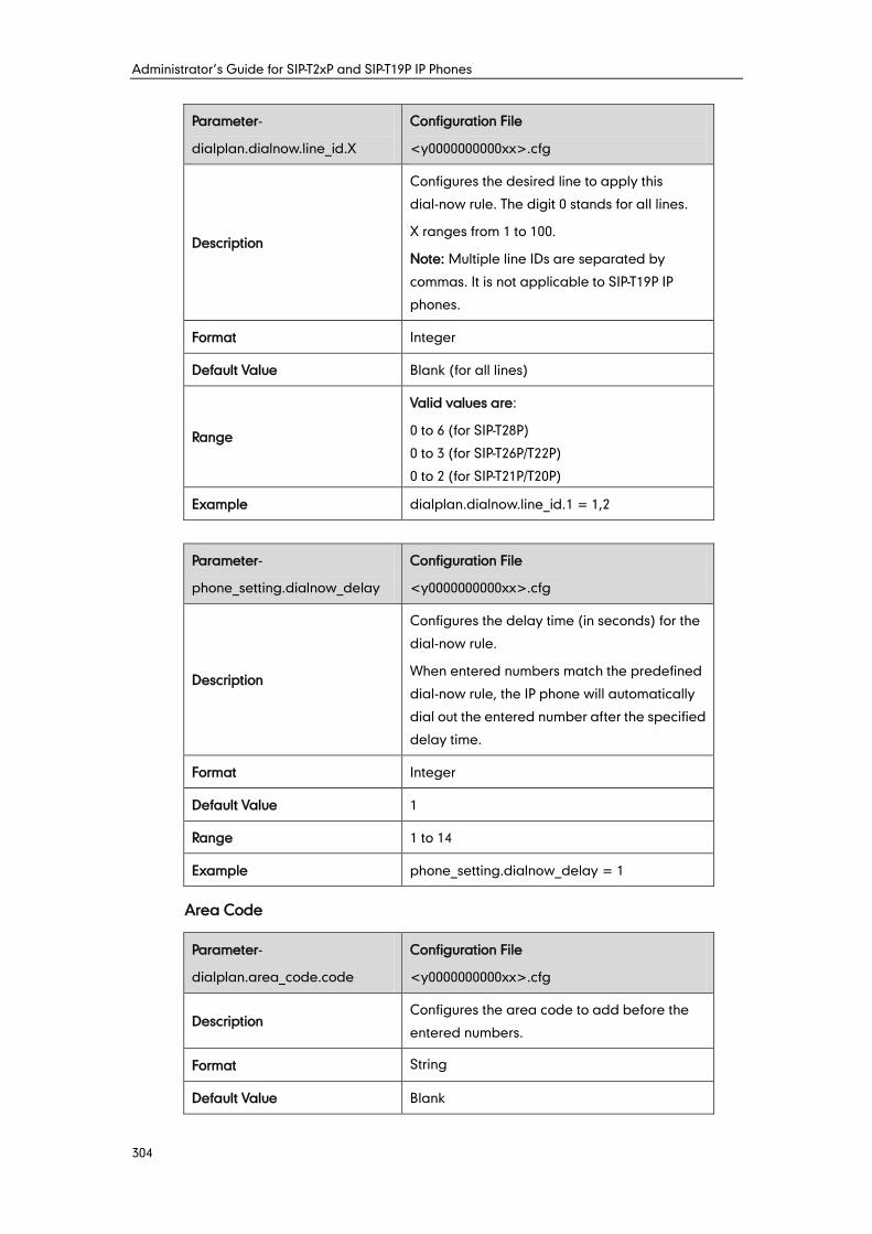
Administrator’s Guide for SIP-T2xP and SIP-T19P IP Phones
304
Parameter-
dialplan.dialnow.line_id.X
Configuration File
<y0000000000xx>.cfg
Description
Configures the desired line to apply this
dial-now rule. The digit 0 stands for all lines.
X ranges from 1 to 100.
Note: Multiple line IDs are separated by
commas. It is not applicable to SIP-T19P IP
phones.
Format Integer
Default Value Blank (for all lines)
Range
Valid values are:
0 to 6 (for SIP-T28P)
0 to 3 (for SIP-T26P/T22P)
0 to 2 (for SIP-T21P/T20P)
Example dialplan.dialnow.line_id.1 = 1,2
Parameter-
phone_setting.dialnow_delay
Configuration File
<y0000000000xx>.cfg
Description
Configures the delay time (in seconds) for the
dial-now rule.
When entered numbers match the predefined
dial-now rule, the IP phone will automatically
dial out the entered number after the specified
delay time.
Format Integer
Default Value 1
Range 1 to 14
Example phone_setting.dialnow_delay = 1
Area Code
Parameter-
dialplan.area_code.code
Configuration File
<y0000000000xx>.cfg
Description Configures the area code to add before the
entered numbers.
Format String
Default Value Blank
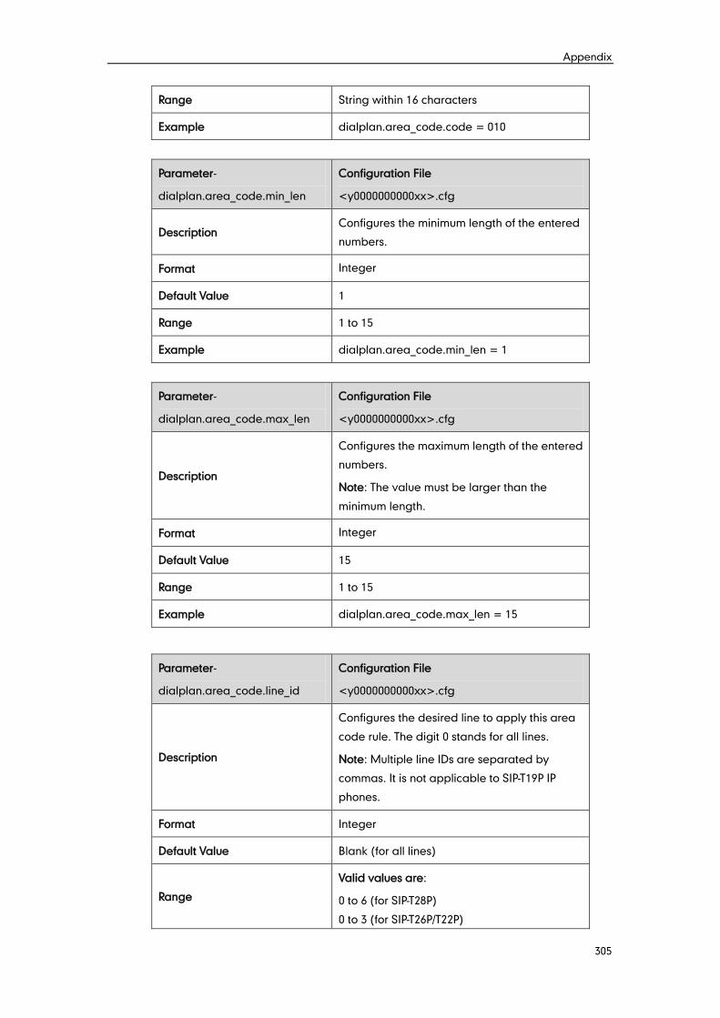
Appendix
305
Range String within 16 characters
Example dialplan.area_code.code = 010
Parameter-
dialplan.area_code.min_len
Configuration File
<y0000000000xx>.cfg
Description Configures the minimum length of the entered
numbers.
Format Integer
Default Value 1
Range 1 to 15
Example dialplan.area_code.min_len = 1
Parameter-
dialplan.area_code.max_len
Configuration File
<y0000000000xx>.cfg
Description
Configures the maximum length of the entered
numbers.
Note: The value must be larger than the
minimum length.
Format Integer
Default Value 15
Range 1 to 15
Example dialplan.area_code.max_len = 15
Parameter-
dialplan.area_code.line_id
Configuration File
<y0000000000xx>.cfg
Description
Configures the desired line to apply this area
code rule. The digit 0 stands for all lines.
Note: Multiple line IDs are separated by
commas. It is not applicable to SIP-T19P IP
phones.
Format Integer
Default Value Blank (for all lines)
Range
Valid values are:
0 to 6 (for SIP-T28P)
0 to 3 (for SIP-T26P/T22P)
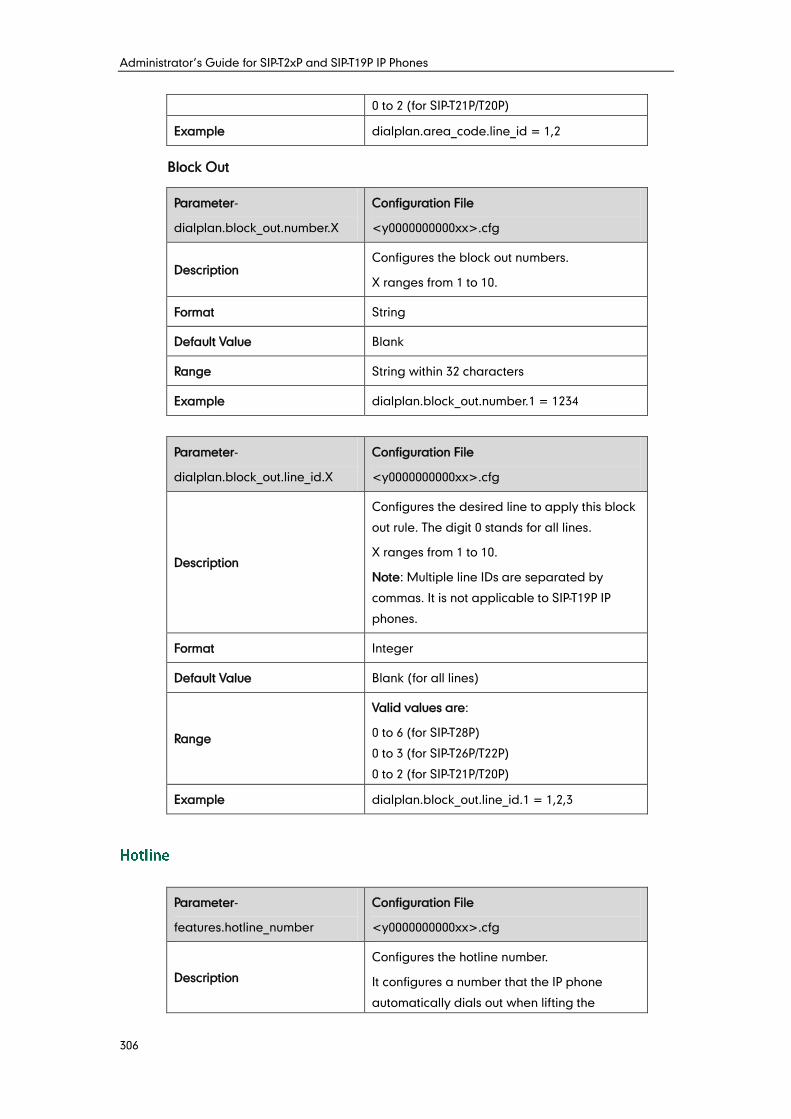
Administrator’s Guide for SIP-T2xP and SIP-T19P IP Phones
306
0 to 2 (for SIP-T21P/T20P)
Example dialplan.area_code.line_id = 1,2
Block Out
Parameter-
dialplan.block_out.number.X
Configuration File
<y0000000000xx>.cfg
Description Configures the block out numbers.
X ranges from 1 to 10.
Format String
Default Value Blank
Range String within 32 characters
Example dialplan.block_out.number.1 = 1234
Parameter-
dialplan.block_out.line_id.X
Configuration File
<y0000000000xx>.cfg
Description
Configures the desired line to apply this block
out rule. The digit 0 stands for all lines.
X ranges from 1 to 10.
Note: Multiple line IDs are separated by
commas. It is not applicable to SIP-T19P IP
phones.
Format Integer
Default Value Blank (for all lines)
Range
Valid values are:
0 to 6 (for SIP-T28P)
0 to 3 (for SIP-T26P/T22P)
0 to 2 (for SIP-T21P/T20P)
Example dialplan.block_out.line_id.1 = 1,2,3
Parameter-
features.hotline_number
Configuration File
<y0000000000xx>.cfg
Description
Configures the hotline number.
It configures a number that the IP phone
automatically dials out when lifting the
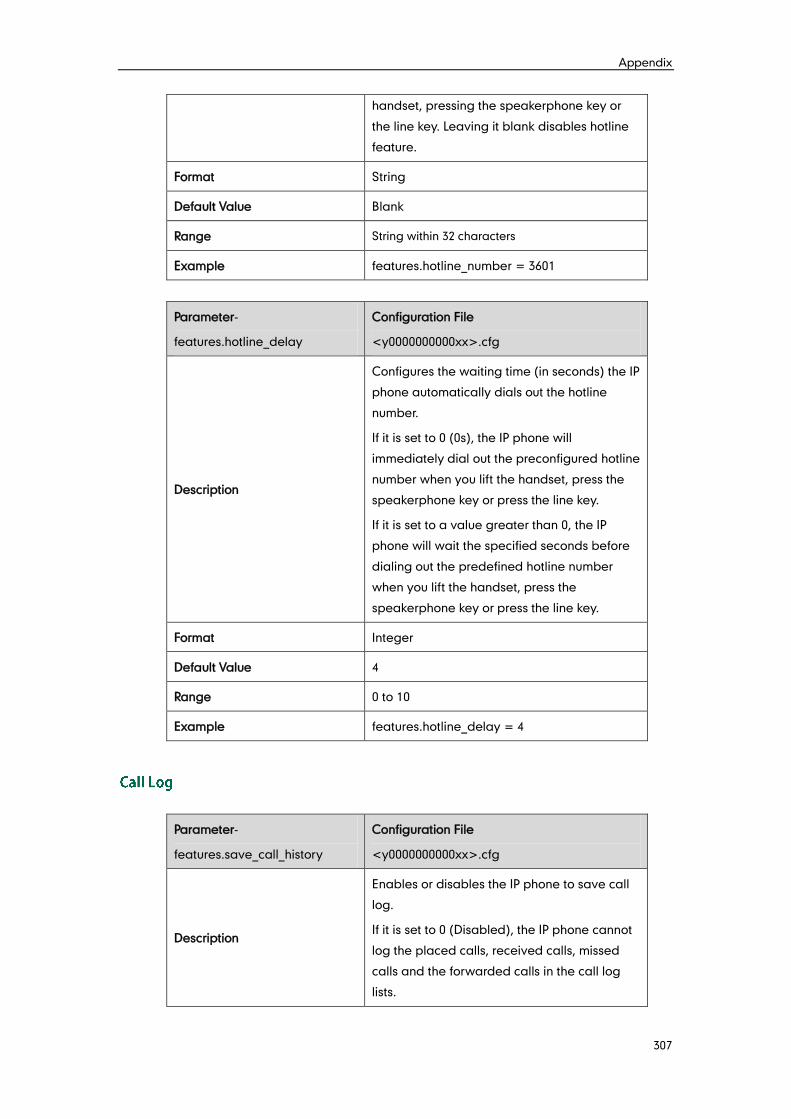
Appendix
307
handset, pressing the speakerphone key or
the line key. Leaving it blank disables hotline
feature.
Format String
Default Value Blank
Range String within 32 characters
Example features.hotline_number = 3601
Parameter-
features.hotline_delay
Configuration File
<y0000000000xx>.cfg
Description
Configures the waiting time (in seconds) the IP
phone automatically dials out the hotline
number.
If it is set to 0 (0s), the IP phone will
immediately dial out the preconfigured hotline
number when you lift the handset, press the
speakerphone key or press the line key.
If it is set to a value greater than 0, the IP
phone will wait the specified seconds before
dialing out the predefined hotline number
when you lift the handset, press the
speakerphone key or press the line key.
Format Integer
Default Value 4
Range 0 to 10
Example features.hotline_delay = 4
Parameter-
features.save_call_history
Configuration File
<y0000000000xx>.cfg
Description
Enables or disables the IP phone to save call
log.
If it is set to 0 (Disabled), the IP phone cannot
log the placed calls, received calls, missed
calls and the forwarded calls in the call log
lists.
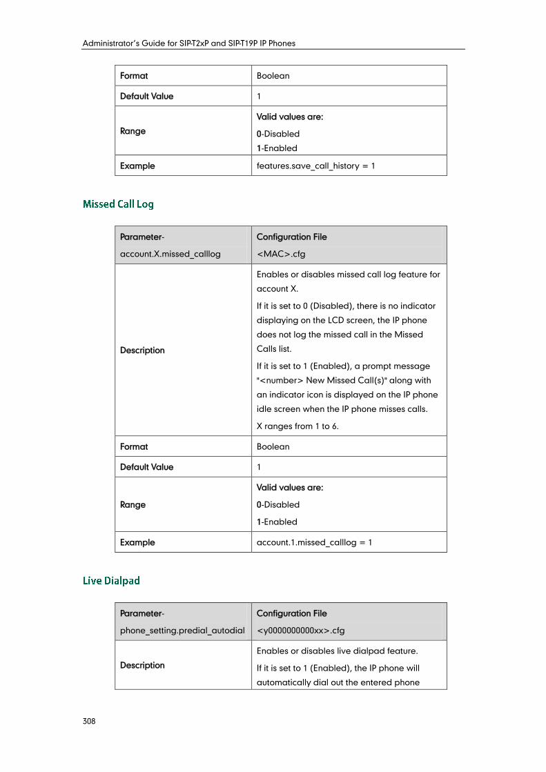
Administrator’s Guide for SIP-T2xP and SIP-T19P IP Phones
308
Format Boolean
Default Value 1
Range
Valid values are:
0-Disabled
1-Enabled
Example features.save_call_history = 1
Parameter-
account.X.missed_calllog
Configuration File
<MAC>.cfg
Description
Enables or disables missed call log feature for
account X.
If it is set to 0 (Disabled), there is no indicator
displaying on the LCD screen, the IP phone
does not log the missed call in the Missed
Calls list.
If it is set to 1 (Enabled), a prompt message
"<number> New Missed Call(s)" along with
an indicator icon is displayed on the IP phone
idle screen when the IP phone misses calls.
X ranges from 1 to 6.
Format Boolean
Default Value 1
Range
Valid values are:
0-Disabled
1-Enabled
Example account.1.missed_calllog = 1
Parameter-
phone_setting.predial_autodial
Configuration File
<y0000000000xx>.cfg
Description
Enables or disables live dialpad feature.
If it is set to 1 (Enabled), the IP phone will
automatically dial out the entered phone
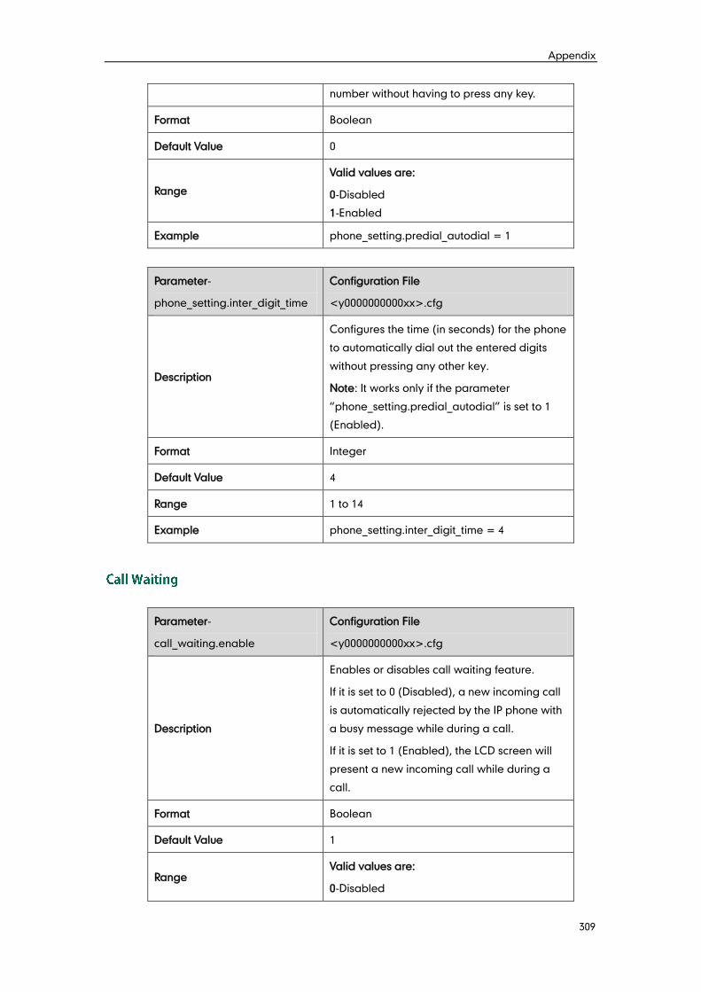
Appendix
309
number without having to press any key.
Format Boolean
Default Value 0
Range
Valid values are:
0-Disabled
1-Enabled
Example phone_setting.predial_autodial = 1
Parameter-
phone_setting.inter_digit_time
Configuration File
<y0000000000xx>.cfg
Description
Configures the time (in seconds) for the phone
to automatically dial out the entered digits
without pressing any other key.
Note: It works only if the parameter
“phone_setting.predial_autodial” is set to 1
(Enabled).
Format Integer
Default Value 4
Range 1 to 14
Example phone_setting.inter_digit_time = 4
Parameter-
call_waiting.enable
Configuration File
<y0000000000xx>.cfg
Description
Enables or disables call waiting feature.
If it is set to 0 (Disabled), a new incoming call
is automatically rejected by the IP phone with
a busy message while during a call.
If it is set to 1 (Enabled), the LCD screen will
present a new incoming call while during a
call.
Format Boolean
Default Value 1
Range Valid values are:
0-Disabled
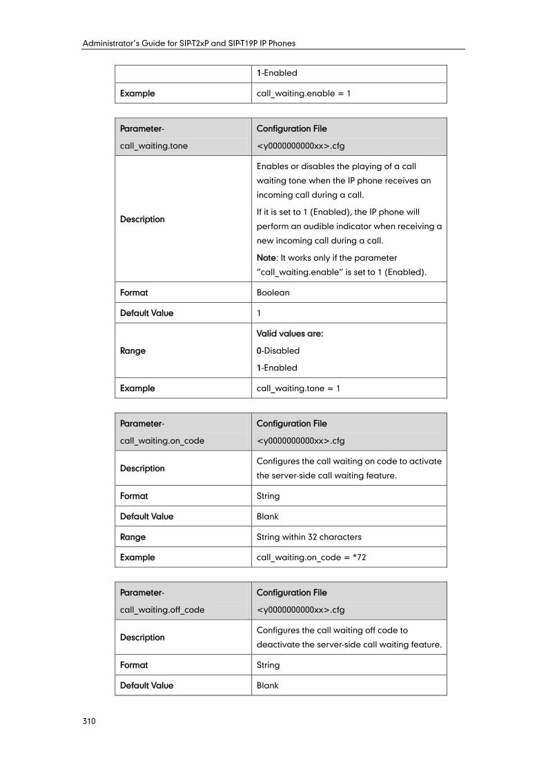
Administrator’s Guide for SIP-T2xP and SIP-T19P IP Phones
310
1-Enabled
Example call_waiting.enable = 1
Parameter-
call_waiting.tone
Configuration File
<y0000000000xx>.cfg
Description
Enables or disables the playing of a call
waiting tone when the IP phone receives an
incoming call during a call.
If it is set to 1 (Enabled), the IP phone will
perform an audible indicator when receiving a
new incoming call during a call.
Note: It works only if the parameter
“call_waiting.enable” is set to 1 (Enabled).
Format Boolean
Default Value 1
Range
Valid values are:
0-Disabled
1-Enabled
Example call_waiting.tone = 1
Parameter-
call_waiting.on_code
Configuration File
<y0000000000xx>.cfg
Description Configures the call waiting on code to activate
the server-side call waiting feature.
Format String
Default Value Blank
Range String within 32 characters
Example call_waiting.on_code = *72
Parameter-
call_waiting.off_code
Configuration File
<y0000000000xx>.cfg
Description Configures the call waiting off code to
deactivate the server-side call waiting feature.
Format String
Default Value Blank
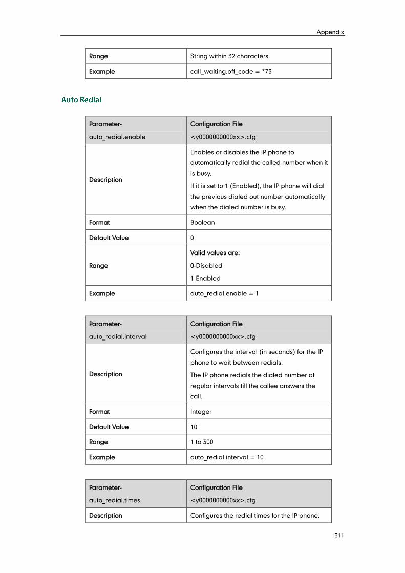
Appendix
311
Range String within 32 characters
Example call_waiting.off_code = *73
Parameter-
auto_redial.enable
Configuration File
<y0000000000xx>.cfg
Description
Enables or disables the IP phone to
automatically redial the called number when it
is busy.
If it is set to 1 (Enabled), the IP phone will dial
the previous dialed out number automatically
when the dialed number is busy.
Format Boolean
Default Value 0
Range
Valid values are:
0-Disabled
1-Enabled
Example auto_redial.enable = 1
Parameter-
auto_redial.interval
Configuration File
<y0000000000xx>.cfg
Description
Configures the interval (in seconds) for the IP
phone to wait between redials.
The IP phone redials the dialed number at
regular intervals till the callee answers the
call.
Format Integer
Default Value 10
Range 1 to 300
Example auto_redial.interval = 10
Parameter-
auto_redial.times
Configuration File
<y0000000000xx>.cfg
Description Configures the redial times for the IP phone.
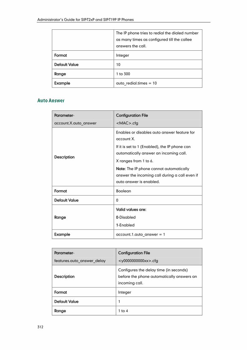
Administrator’s Guide for SIP-T2xP and SIP-T19P IP Phones
312
The IP phone tries to redial the dialed number
as many times as configured till the callee
answers the call.
Format Integer
Default Value 10
Range 1 to 300
Example auto_redial.times = 10
Parameter-
account.X.auto_answer
Configuration File
<MAC>.cfg
Description
Enables or disables auto answer feature for
account X.
If it is set to 1 (Enabled), the IP phone can
automatically answer an incoming call.
X ranges from 1 to 6.
Note: The IP phone cannot automatically
answer the incoming call during a call even if
auto answer is enabled.
Format Boolean
Default Value 0
Range
Valid values are:
0-Disabled
1-Enabled
Example account.1.auto_answer = 1
Parameter-
features.auto_answer_delay
Configuration File
<y0000000000xx>.cfg
Description
Configures the delay time (in seconds)
before the phone automatically answers an
incoming call.
Format Integer
Default Value 1
Range 1 to 4
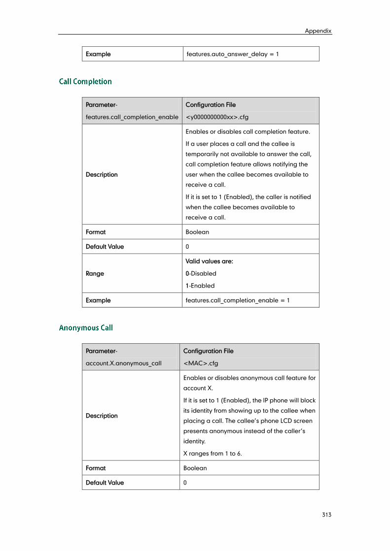
Appendix
313
Example features.auto_answer_delay = 1
Parameter-
features.call_completion_enable
Configuration File
<y0000000000xx>.cfg
Description
Enables or disables call completion feature.
If a user places a call and the callee is
temporarily not available to answer the call,
call completion feature allows notifying the
user when the callee becomes available to
receive a call.
If it is set to 1 (Enabled), the caller is notified
when the callee becomes available to
receive a call.
Format Boolean
Default Value 0
Range
Valid values are:
0-Disabled
1-Enabled
Example features.call_completion_enable = 1
Parameter-
account.X.anonymous_call
Configuration File
<MAC>.cfg
Description
Enables or disables anonymous call feature for
account X.
If it is set to 1 (Enabled), the IP phone will block
its identity from showing up to the callee when
placing a call. The callee’s phone LCD screen
presents anonymous instead of the caller’s
identity.
X ranges from 1 to 6.
Format Boolean
Default Value 0
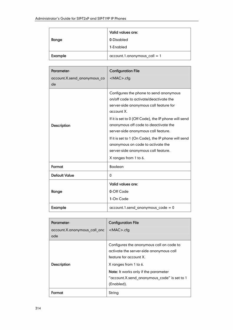
Administrator’s Guide for SIP-T2xP and SIP-T19P IP Phones
314
Range
Valid values are:
0-Disabled
1-Enabled
Example account.1.anonymous_call = 1
Parameter-
account.X.send_anonymous_co
de
Configuration File
<MAC>.cfg
Description
Configures the phone to send anonymous
on/off code to activate/deactivate the
server-side anonymous call feature for
account X.
If it is set to 0 (Off Code), the IP phone will send
anonymous off code to deactivate the
server-side anonymous call feature.
If it is set to 1 (On Code), the IP phone will send
anonymous on code to activate the
server-side anonymous call feature.
X ranges from 1 to 6.
Format Boolean
Default Value 0
Range
Valid values are:
0-Off Code
1-On Code
Example account.1.send_anonymous_code = 0
Parameter-
account.X.anonymous_call_onc
ode
Configuration File
<MAC>.cfg
Description
Configures the anonymous call on code to
activate the server-side anonymous call
feature for account X.
X ranges from 1 to 6.
Note: It works only if the parameter
“account.X.send_anonymous_code” is set to 1
(Enabled).
Format String
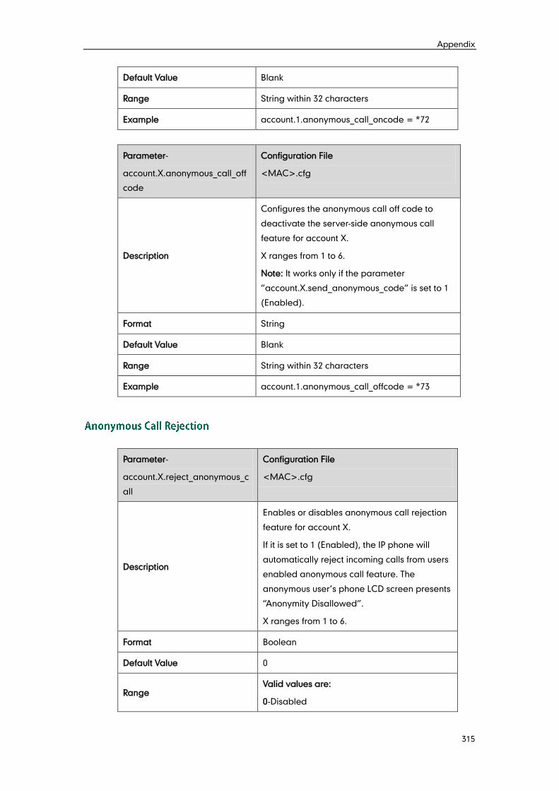
Appendix
315
Default Value Blank
Range String within 32 characters
Example account.1.anonymous_call_oncode = *72
Parameter-
account.X.anonymous_call_off
code
Configuration File
<MAC>.cfg
Description
Configures the anonymous call off code to
deactivate the server-side anonymous call
feature for account X.
X ranges from 1 to 6.
Note: It works only if the parameter
“account.X.send_anonymous_code” is set to 1
(Enabled).
Format String
Default Value Blank
Range String within 32 characters
Example account.1.anonymous_call_offcode = *73
Parameter-
account.X.reject_anonymous_c
all
Configuration File
<MAC>.cfg
Description
Enables or disables anonymous call rejection
feature for account X.
If it is set to 1 (Enabled), the IP phone will
automatically reject incoming calls from users
enabled anonymous call feature. The
anonymous user’s phone LCD screen presents
“Anonymity Disallowed”.
X ranges from 1 to 6.
Format Boolean
Default Value 0
Range Valid values are:
0-Disabled
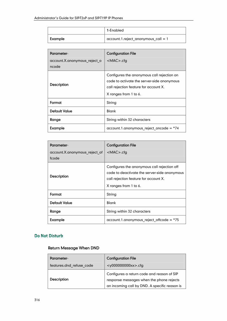
Administrator’s Guide for SIP-T2xP and SIP-T19P IP Phones
316
1-Enabled
Example account.1.reject_anonymous_call = 1
Parameter-
account.X.anonymous_reject_o
ncode
Configuration File
<MAC>.cfg
Description
Configures the anonymous call rejection on
code to activate the server-side anonymous
call rejection feature for account X.
X ranges from 1 to 6.
Format String
Default Value Blank
Range String within 32 characters
Example account.1.anonymous_reject_oncode = *74
Parameter-
account.X.anonymous_reject_of
fcode
Configuration File
<MAC>.cfg
Description
Configures the anonymous call rejection off
code to deactivate the server-side anonymous
call rejection feature for account X.
X ranges from 1 to 6.
Format String
Default Value Blank
Range String within 32 characters
Example account.1.anonymous_reject_offcode = *75
Return Message When DND
Parameter-
features.dnd_refuse_code
Configuration File
<y0000000000xx>.cfg
Description
Configures a return code and reason of SIP
response messages when the phone rejects
an incoming call by DND. A specific reason is
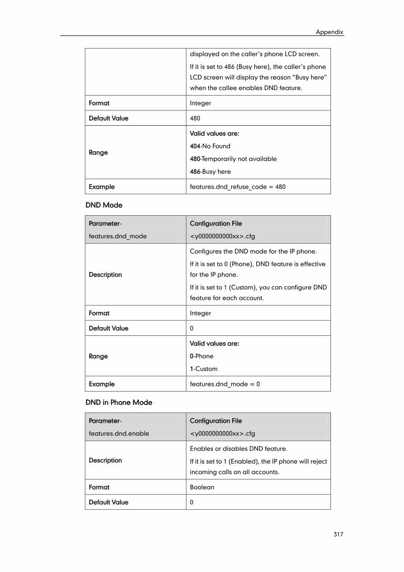
Appendix
317
displayed on the caller’s phone LCD screen.
If it is set to 486 (Busy here), the caller’s phone
LCD screen will display the reason “Busy here”
when the callee enables DND feature.
Format Integer
Default Value 480
Range
Valid values are:
404-No Found
480-Temporarily not available
486-Busy here
Example features.dnd_refuse_code = 480
DND Mode
Parameter-
features.dnd_mode
Configuration File
<y0000000000xx>.cfg
Description
Configures the DND mode for the IP phone.
If it is set to 0 (Phone), DND feature is effective
for the IP phone.
If it is set to 1 (Custom), you can configure DND
feature for each account.
Format Integer
Default Value 0
Range
Valid values are:
0-Phone
1-Custom
Example features.dnd_mode = 0
DND in Phone Mode
Parameter-
features.dnd.enable
Configuration File
<y0000000000xx>.cfg
Description
Enables or disables DND feature.
If it is set to 1 (Enabled), the IP phone will reject
incoming calls on all accounts.
Format Boolean
Default Value 0
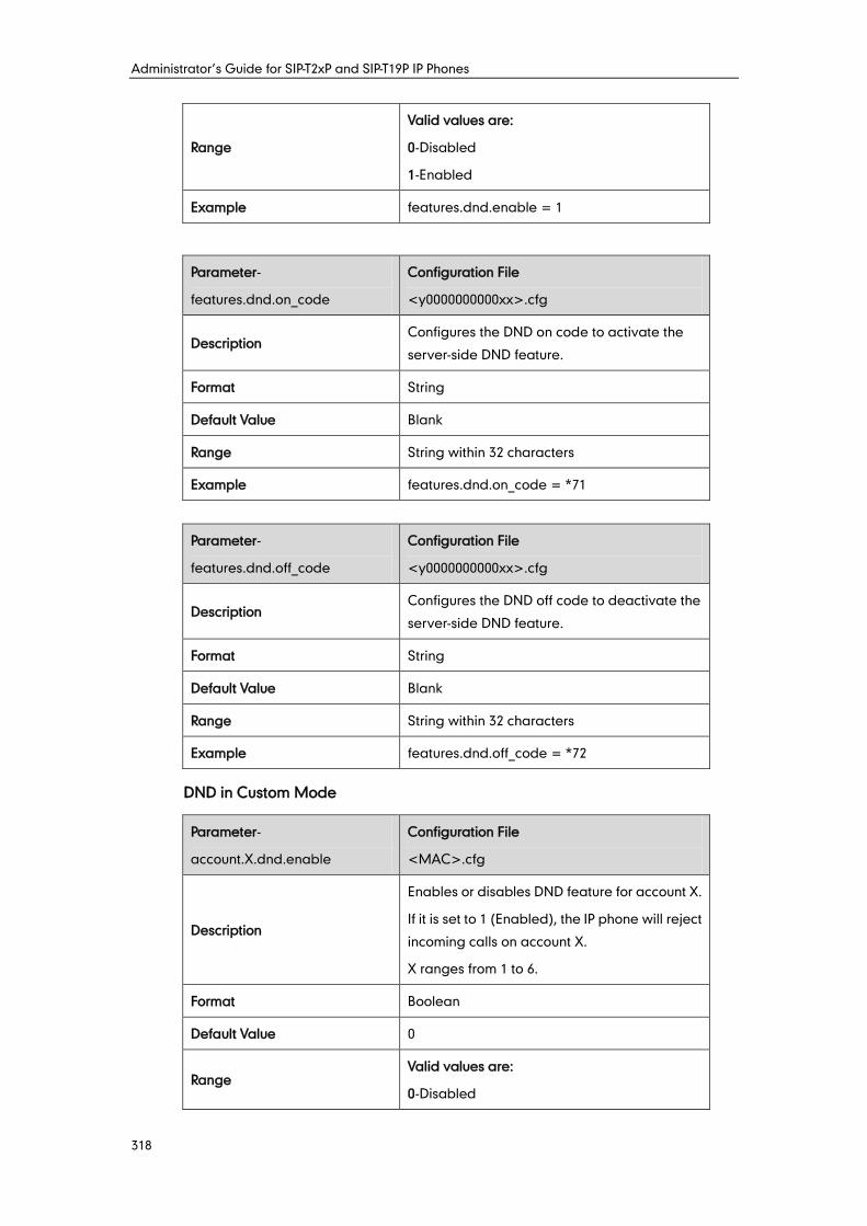
Administrator’s Guide for SIP-T2xP and SIP-T19P IP Phones
318
Range
Valid values are:
0-Disabled
1-Enabled
Example features.dnd.enable = 1
Parameter-
features.dnd.on_code
Configuration File
<y0000000000xx>.cfg
Description Configures the DND on code to activate the
server-side DND feature.
Format String
Default Value Blank
Range String within 32 characters
Example features.dnd.on_code = *71
Parameter-
features.dnd.off_code
Configuration File
<y0000000000xx>.cfg
Description Configures the DND off code to deactivate the
server-side DND feature.
Format String
Default Value Blank
Range String within 32 characters
Example features.dnd.off_code = *72
DND in Custom Mode
Parameter-
account.X.dnd.enable
Configuration File
<MAC>.cfg
Description
Enables or disables DND feature for account X.
If it is set to 1 (Enabled), the IP phone will reject
incoming calls on account X.
X ranges from 1 to 6.
Format Boolean
Default Value 0
Range Valid values are:
0-Disabled
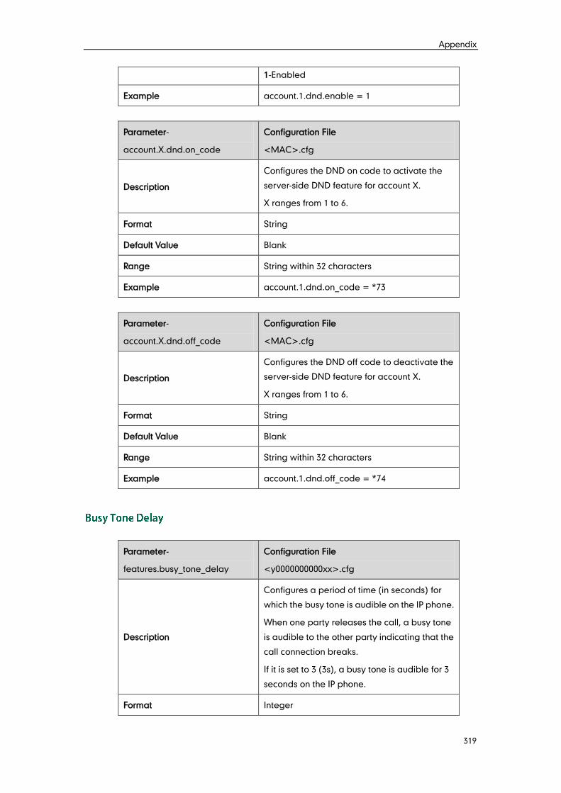
Appendix
319
1-Enabled
Example account.1.dnd.enable = 1
Parameter-
account.X.dnd.on_code
Configuration File
<MAC>.cfg
Description
Configures the DND on code to activate the
server-side DND feature for account X.
X ranges from 1 to 6.
Format String
Default Value Blank
Range String within 32 characters
Example account.1.dnd.on_code = *73
Parameter-
account.X.dnd.off_code
Configuration File
<MAC>.cfg
Description
Configures the DND off code to deactivate the
server-side DND feature for account X.
X ranges from 1 to 6.
Format String
Default Value Blank
Range String within 32 characters
Example account.1.dnd.off_code = *74
Parameter-
features.busy_tone_delay
Configuration File
<y0000000000xx>.cfg
Description
Configures a period of time (in seconds) for
which the busy tone is audible on the IP phone.
When one party releases the call, a busy tone
is audible to the other party indicating that the
call connection breaks.
If it is set to 3 (3s), a busy tone is audible for 3
seconds on the IP phone.
Format Integer
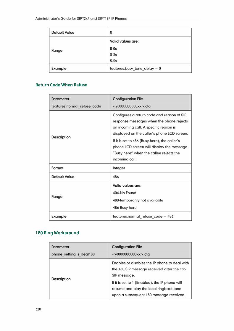
Administrator’s Guide for SIP-T2xP and SIP-T19P IP Phones
320
Default Value 0
Range
Valid values are:
0-0s
3-3s
5-5s
Example features.busy_tone_delay = 0
Parameter-
features.normal_refuse_code
Configuration File
<y0000000000xx>.cfg
Description
Configures a return code and reason of SIP
response messages when the phone rejects
an incoming call. A specific reason is
displayed on the caller’s phone LCD screen.
If it is set to 486 (Busy here), the caller’s
phone LCD screen will display the message
“Busy here” when the callee rejects the
incoming call.
Format Integer
Default Value 486
Range
Valid values are:
404-No Found
480-Temporarily not available
486-Busy here
Example features.normal_refuse_code = 486
Parameter-
phone_setting.is_deal180
Configuration File
<y0000000000xx>.cfg
Description
Enables or disables the IP phone to deal with
the 180 SIP message received after the 183
SIP message.
If it is set to 1 (Enabled), the IP phone will
resume and play the local ringback tone
upon a subsequent 180 message received.
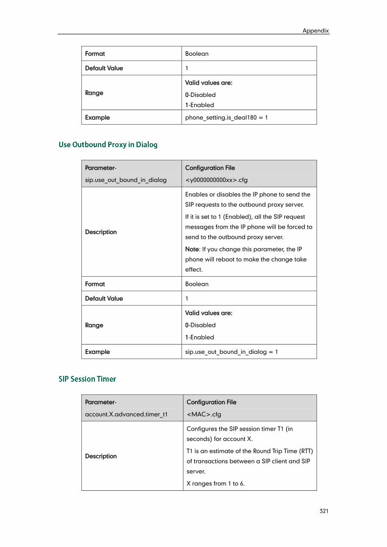
Appendix
321
Format Boolean
Default Value 1
Range
Valid values are:
0-Disabled
1-Enabled
Example phone_setting.is_deal180 = 1
Parameter-
sip.use_out_bound_in_dialog
Configuration File
<y0000000000xx>.cfg
Description
Enables or disables the IP phone to send the
SIP requests to the outbound proxy server.
If it is set to 1 (Enabled), all the SIP request
messages from the IP phone will be forced to
send to the outbound proxy server.
Note: If you change this parameter, the IP
phone will reboot to make the change take
effect.
Format Boolean
Default Value 1
Range
Valid values are:
0-Disabled
1-Enabled
Example sip.use_out_bound_in_dialog = 1
Parameter-
account.X.advanced.timer_t1
Configuration File
<MAC>.cfg
Description
Configures the SIP session timer T1 (in
seconds) for account X.
T1 is an estimate of the Round Trip Time (RTT)
of transactions between a SIP client and SIP
server.
X ranges from 1 to 6.
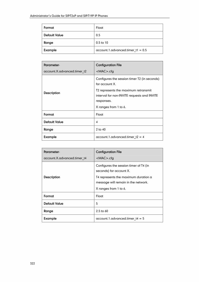
Administrator’s Guide for SIP-T2xP and SIP-T19P IP Phones
322
Format Float
Default Value 0.5
Range 0.5 to 10
Example account.1.advanced.timer_t1 = 0.5
Parameter-
account.X.advanced.timer_t2
Configuration File
<MAC>.cfg
Description
Configures the session timer T2 (in seconds)
for account X.
T2 represents the maximum retransmit
interval for non-INVITE requests and INVITE
responses.
X ranges from 1 to 6.
Format Float
Default Value 4
Range 2 to 40
Example account.1.advanced.timer_t2 = 4
Parameter-
account.X.advanced.timer_t4
Configuration File
<MAC>.cfg
Description
Configures the session timer of T4 (in
seconds) for account X.
T4 represents the maximum duration a
message will remain in the network.
X ranges from 1 to 6.
Format Float
Default Value 5
Range 2.5 to 60
Example account.1.advanced.timer_t4 = 5
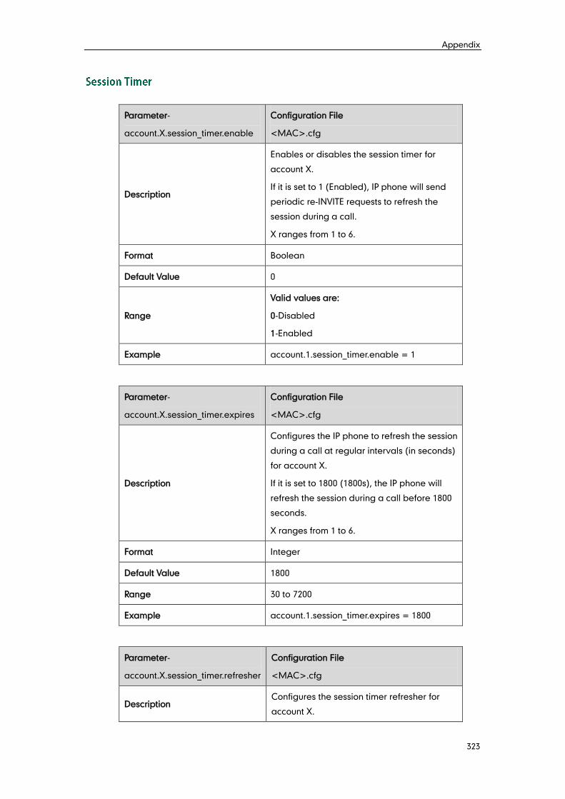
Appendix
323
Parameter-
account.X.session_timer.enable
Configuration File
<MAC>.cfg
Description
Enables or disables the session timer for
account X.
If it is set to 1 (Enabled), IP phone will send
periodic re-INVITE requests to refresh the
session during a call.
X ranges from 1 to 6.
Format Boolean
Default Value 0
Range
Valid values are:
0-Disabled
1-Enabled
Example account.1.session_timer.enable = 1
Parameter-
account.X.session_timer.expires
Configuration File
<MAC>.cfg
Description
Configures the IP phone to refresh the session
during a call at regular intervals (in seconds)
for account X.
If it is set to 1800 (1800s), the IP phone will
refresh the session during a call before 1800
seconds.
X ranges from 1 to 6.
Format Integer
Default Value 1800
Range 30 to 7200
Example account.1.session_timer.expires = 1800
Parameter-
account.X.session_timer.refresher
Configuration File
<MAC>.cfg
Description Configures the session timer refresher for
account X.
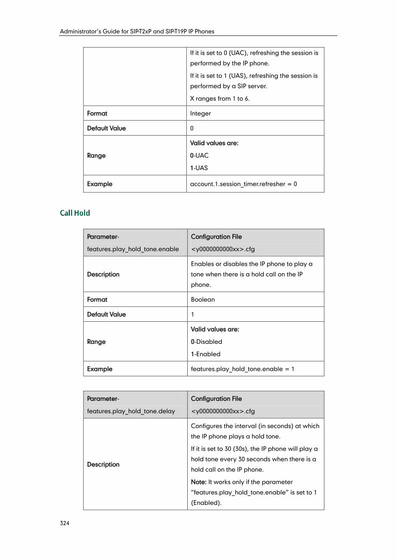
Administrator’s Guide for SIP-T2xP and SIP-T19P IP Phones
324
If it is set to 0 (UAC), refreshing the session is
performed by the IP phone.
If it is set to 1 (UAS), refreshing the session is
performed by a SIP server.
X ranges from 1 to 6.
Format Integer
Default Value 0
Range
Valid values are:
0-UAC
1-UAS
Example account.1.session_timer.refresher = 0
Parameter-
features.play_hold_tone.enable
Configuration File
<y0000000000xx>.cfg
Description
Enables or disables the IP phone to play a
tone when there is a hold call on the IP
phone.
Format Boolean
Default Value 1
Range
Valid values are:
0-Disabled
1-Enabled
Example features.play_hold_tone.enable = 1
Parameter-
features.play_hold_tone.delay
Configuration File
<y0000000000xx>.cfg
Description
Configures the interval (in seconds) at which
the IP phone plays a hold tone.
If it is set to 30 (30s), the IP phone will play a
hold tone every 30 seconds when there is a
hold call on the IP phone.
Note: It works only if the parameter
“features.play_hold_tone.enable” is set to 1
(Enabled).
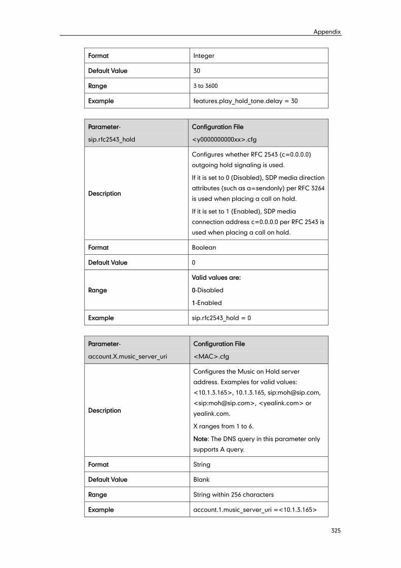
Appendix
325
Format Integer
Default Value 30
Range 3 to 3600
Example features.play_hold_tone.delay = 30
Parameter-
sip.rfc2543_hold
Configuration File
<y0000000000xx>.cfg
Description
Configures whether RFC 2543 (c=0.0.0.0)
outgoing hold signaling is used.
If it is set to 0 (Disabled), SDP media direction
attributes (such as a=sendonly) per RFC 3264
is used when placing a call on hold.
If it is set to 1 (Enabled), SDP media
connection address c=0.0.0.0 per RFC 2543 is
used when placing a call on hold.
Format Boolean
Default Value 0
Range
Valid values are:
0-Disabled
1-Enabled
Example sip.rfc2543_hold = 0
Parameter-
account.X.music_server_uri
Configuration File
<MAC>.cfg
Description
Configures the Music on Hold server
address. Examples for valid values:
<10.1.3.165>, 10.1.3.165, sip:[email protected],
<sip:[email protected]>, <yealink.com> or
yealink.com.
X ranges from 1 to 6.
Note: The DNS query in this parameter only
supports A query.
Format String
Default Value Blank
Range String within 256 characters
Example account.1.music_server_uri =<10.1.3.165>
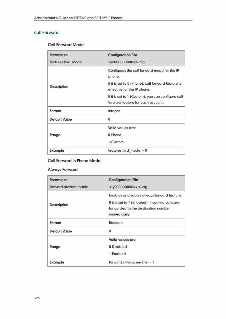
Administrator’s Guide for SIP-T2xP and SIP-T19P IP Phones
326
Call Forward Mode
Parameter-
features.fwd_mode
Configuration File
<y0000000000xx>.cfg
Description
Configures the call forward mode for the IP
phone.
If it is set to 0 (Phone), call forward feature is
effective for the IP phone.
If it is set to 1 (Custom), you can configure call
forward feature for each account.
Format Integer
Default Value 0
Range
Valid values are:
0-Phone
1-Custom
Example features.fwd_mode = 0
Call Forward in Phone Mode
Always Forward
Parameter-
forward.always.enable
Configuration File
< y0000000000xx >.cfg
Description
Enables or disables always forward feature.
If it is set to 1 (Enabled), incoming calls are
forwarded to the destination number
immediately.
Format Boolean
Default Value 0
Range
Valid values are:
0-Disabled
1-Enabled
Example forward.always.enable = 1
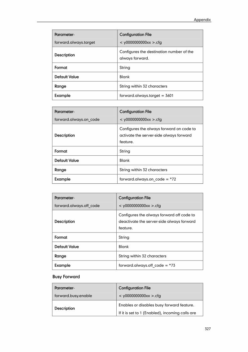
Appendix
327
Parameter-
forward.always.target
Configuration File
< y0000000000xx >.cfg
Description Configures the destination number of the
always forward.
Format String
Default Value Blank
Range String within 32 characters
Example forward.always.target = 3601
Parameter-
forward.always.on_code
Configuration File
< y0000000000xx >.cfg
Description
Configures the always forward on code to
activate the server-side always forward
feature.
Format String
Default Value Blank
Range String within 32 characters
Example forward.always.on_code = *72
Parameter-
forward.always.off_code
Configuration File
< y0000000000xx >.cfg
Description
Configures the always forward off code to
deactivate the server-side always forward
feature.
Format String
Default Value Blank
Range String within 32 characters
Example forward.always.off_code = *73
Busy Forward
Parameter-
forward.busy.enable
Configuration File
< y0000000000xx >.cfg
Description Enables or disables busy forward feature.
If it is set to 1 (Enabled), incoming calls are
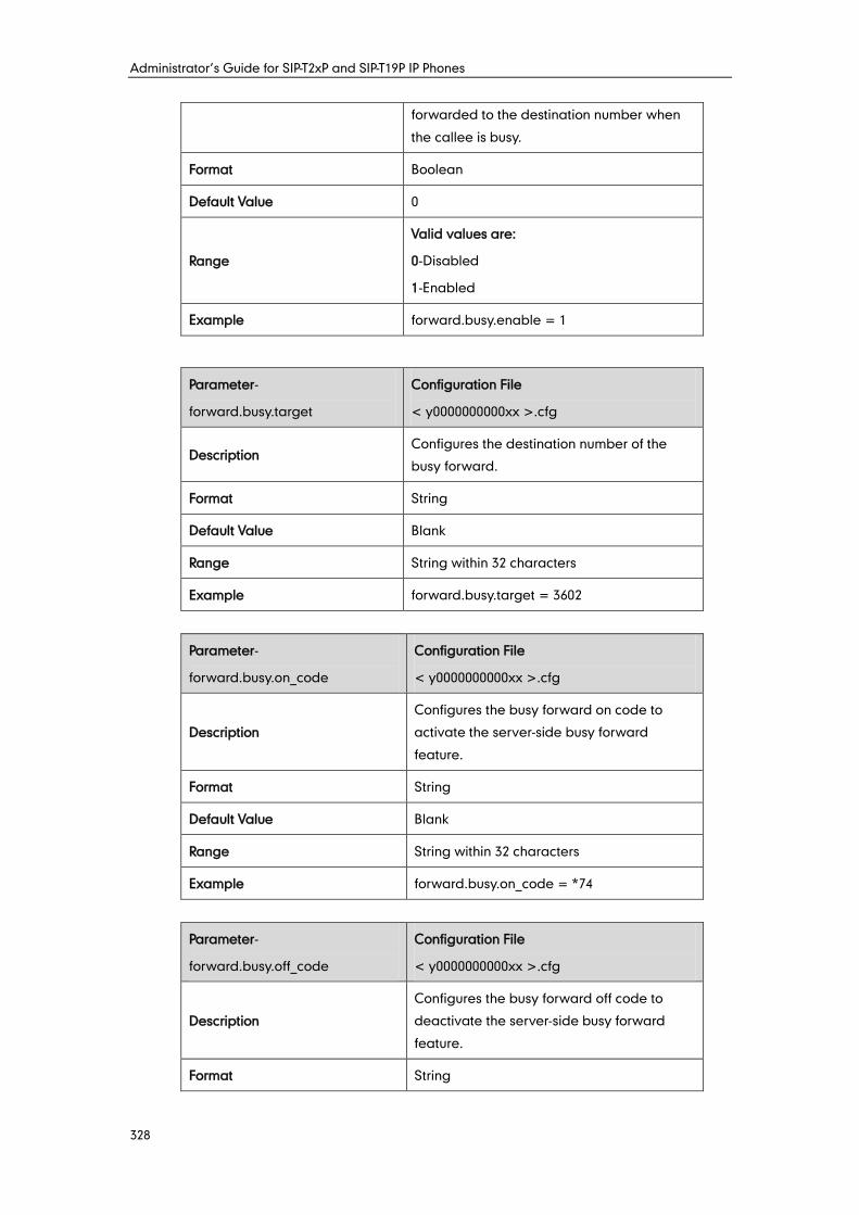
Administrator’s Guide for SIP-T2xP and SIP-T19P IP Phones
328
forwarded to the destination number when
the callee is busy.
Format Boolean
Default Value 0
Range
Valid values are:
0-Disabled
1-Enabled
Example forward.busy.enable = 1
Parameter-
forward.busy.target
Configuration File
< y0000000000xx >.cfg
Description Configures the destination number of the
busy forward.
Format String
Default Value Blank
Range String within 32 characters
Example forward.busy.target = 3602
Parameter-
forward.busy.on_code
Configuration File
< y0000000000xx >.cfg
Description
Configures the busy forward on code to
activate the server-side busy forward
feature.
Format String
Default Value Blank
Range String within 32 characters
Example forward.busy.on_code = *74
Parameter-
forward.busy.off_code
Configuration File
< y0000000000xx >.cfg
Description
Configures the busy forward off code to
deactivate the server-side busy forward
feature.
Format String
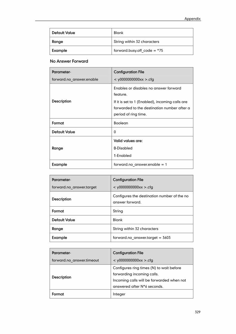
Appendix
329
Default Value Blank
Range String within 32 characters
Example forward.busy.off_code = *75
No Answer Forward
Parameter-
forward.no_answer.enable
Configuration File
< y0000000000xx >.cfg
Description
Enables or disables no answer forward
feature.
If it is set to 1 (Enabled), incoming calls are
forwarded to the destination number after a
period of ring time.
Format Boolean
Default Value 0
Range
Valid values are:
0-Disabled
1-Enabled
Example forward.no_answer.enable = 1
Parameter-
forward.no_answer.target
Configuration File
< y0000000000xx >.cfg
Description Configures the destination number of the no
answer forward.
Format String
Default Value Blank
Range String within 32 characters
Example forward.no_answer.target = 3603
Parameter-
forward.no_answer.timeout
Configuration File
< y0000000000xx >.cfg
Description
Configures ring times (N) to wait before
forwarding incoming calls.
Incoming calls will be forwarded when not
answered after N*6 seconds.
Format Integer
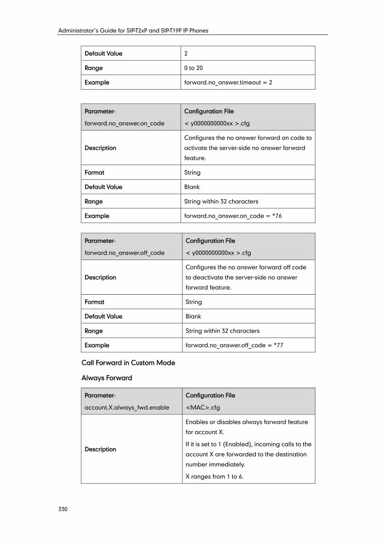
Administrator’s Guide for SIP-T2xP and SIP-T19P IP Phones
330
Default Value 2
Range 0 to 20
Example forward.no_answer.timeout = 2
Parameter-
forward.no_answer.on_code
Configuration File
< y0000000000xx >.cfg
Description
Configures the no answer forward on code to
activate the server-side no answer forward
feature.
Format String
Default Value Blank
Range String within 32 characters
Example forward.no_answer.on_code = *76
Parameter-
forward.no_answer.off_code
Configuration File
< y0000000000xx >.cfg
Description
Configures the no answer forward off code
to deactivate the server-side no answer
forward feature.
Format String
Default Value Blank
Range String within 32 characters
Example forward.no_answer.off_code = *77
Call Forward in Custom Mode
Always Forward
Parameter-
account.X.always_fwd.enable
Configuration File
<MAC>.cfg
Description
Enables or disables always forward feature
for account X.
If it is set to 1 (Enabled), incoming calls to the
account X are forwarded to the destination
number immediately.
X ranges from 1 to 6.
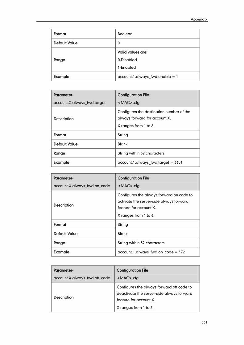
Appendix
331
Format Boolean
Default Value 0
Range
Valid values are:
0-Disabled
1-Enabled
Example account.1.always_fwd.enable = 1
Parameter-
account.X.always_fwd.target
Configuration File
<MAC>.cfg
Description
Configures the destination number of the
always forward for account X.
X ranges from 1 to 6.
Format String
Default Value Blank
Range String within 32 characters
Example account.1.always_fwd.target = 3601
Parameter-
account.X.always_fwd.on_code
Configuration File
<MAC>.cfg
Description
Configures the always forward on code to
activate the server-side always forward
feature for account X.
X ranges from 1 to 6.
Format String
Default Value Blank
Range String within 32 characters
Example account.1.always_fwd.on_code = *72
Parameter-
account.X.always_fwd.off_code
Configuration File
<MAC>.cfg
Description
Configures the always forward off code to
deactivate the server-side always forward
feature for account X.
X ranges from 1 to 6.

Administrator’s Guide for SIP-T2xP and SIP-T19P IP Phones
332
Format String
Default Value Blank
Range String within 32 characters
Example account.1.busy_fwd.off_code = *73
Busy Forward
Parameter-
account.X.busy_fwd.enable
Configuration File
<MAC>.cfg
Description
Enables or disables busy forward feature for
account X.
If it is set to 1 (Enabled), incoming calls to the
account X are forwarded to the destination
number when the callee is busy.
X ranges from 1 to 6.
Format Boolean
Default Value 0
Range
Valid values are:
0-Disabled
1-Enabled
Example account.1.busy_fwd.enable = 1
Parameter-
account.X.busy_fwd.target
Configuration File
<MAC>.cfg
Description
Configures the destination number of the
busy forward for account X.
X ranges from 1 to 6.
Format String
Default Value Blank
Range String within 32 characters
Example account.1.busy_fwd.target = 3602
Parameter-
account.X.busy_fwd.on_code
Configuration File
<MAC>.cfg
Description Configures the busy forward on code to
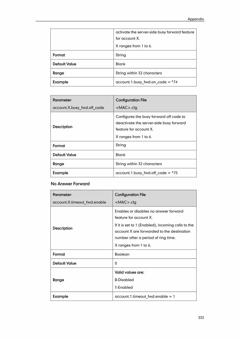
Appendix
333
activate the server-side busy forward feature
for account X.
X ranges from 1 to 6.
Format String
Default Value Blank
Range String within 32 characters
Example account.1.busy_fwd.on_code = *74
Parameter-
account.X.busy_fwd.off_code
Configuration File
<MAC>.cfg
Description
Configures the busy forward off code to
deactivate the server-side busy forward
feature for account X.
X ranges from 1 to 6.
Format String
Default Value Blank
Range String within 32 characters
Example account.1.busy_fwd.off_code = *75
No Answer Forward
Parameter-
account.X.timeout_fwd.enable
Configuration File
<MAC>.cfg
Description
Enables or disables no answer forward
feature for account X.
If it is set to 1 (Enabled), incoming calls to the
account X are forwarded to the destination
number after a period of ring time.
X ranges from 1 to 6.
Format Boolean
Default Value 0
Range
Valid values are:
0-Disabled
1-Enabled
Example account.1.timeout_fwd.enable = 1
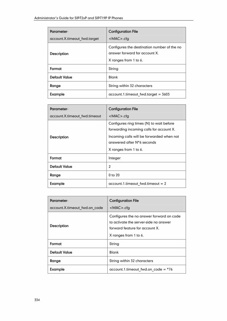
Administrator’s Guide for SIP-T2xP and SIP-T19P IP Phones
334
Parameter-
account.X.timeout_fwd.target
Configuration File
<MAC>.cfg
Description
Configures the destination number of the no
answer forward for account X.
X ranges from 1 to 6.
Format String
Default Value Blank
Range String within 32 characters
Example account.1.timeout_fwd.target = 3603
Parameter-
account.X.timeout_fwd.timeout
Configuration File
<MAC>.cfg
Description
Configures ring times (N) to wait before
forwarding incoming calls for account X.
Incoming calls will be forwarded when not
answered after N*6 seconds
X ranges from 1 to 6.
Format Integer
Default Value 2
Range 0 to 20
Example account.1.timeout_fwd.timeout = 2
Parameter-
account.X.timeout_fwd.on_code
Configuration File
<MAC>.cfg
Description
Configures the no answer forward on code
to activate the server-side no answer
forward feature for account X.
X ranges from 1 to 6.
Format String
Default Value Blank
Range String within 32 characters
Example account.1.timeout_fwd.on_code = *76
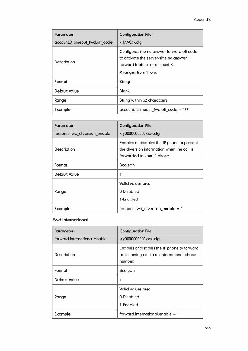
Appendix
335
Parameter-
account.X.timeout_fwd.off_code
Configuration File
<MAC>.cfg
Description
Configures the no answer forward off code
to activate the server-side no answer
forward feature for account X.
X ranges from 1 to 6.
Format String
Default Value Blank
Range String within 32 characters
Example account.1.timeout_fwd.off_code = *77
Parameter-
features.fwd_diversion_enable
Configuration File
<y0000000000xx>.cfg
Description
Enables or disables the IP phone to present
the diversion information when the call is
forwarded to your IP phone.
Format Boolean
Default Value 1
Range
Valid values are:
0-Disabled
1-Enabled
Example features.fwd_diversion_enable = 1
Fwd International
Parameter-
forward.international.enable
Configuration File
<y0000000000xx>.cfg
Description
Enables or disables the IP phone to forward
an incoming call to an international phone
number.
Format Boolean
Default Value 1
Range
Valid values are:
0-Disabled
1-Enabled
Example forward.international.enable = 1
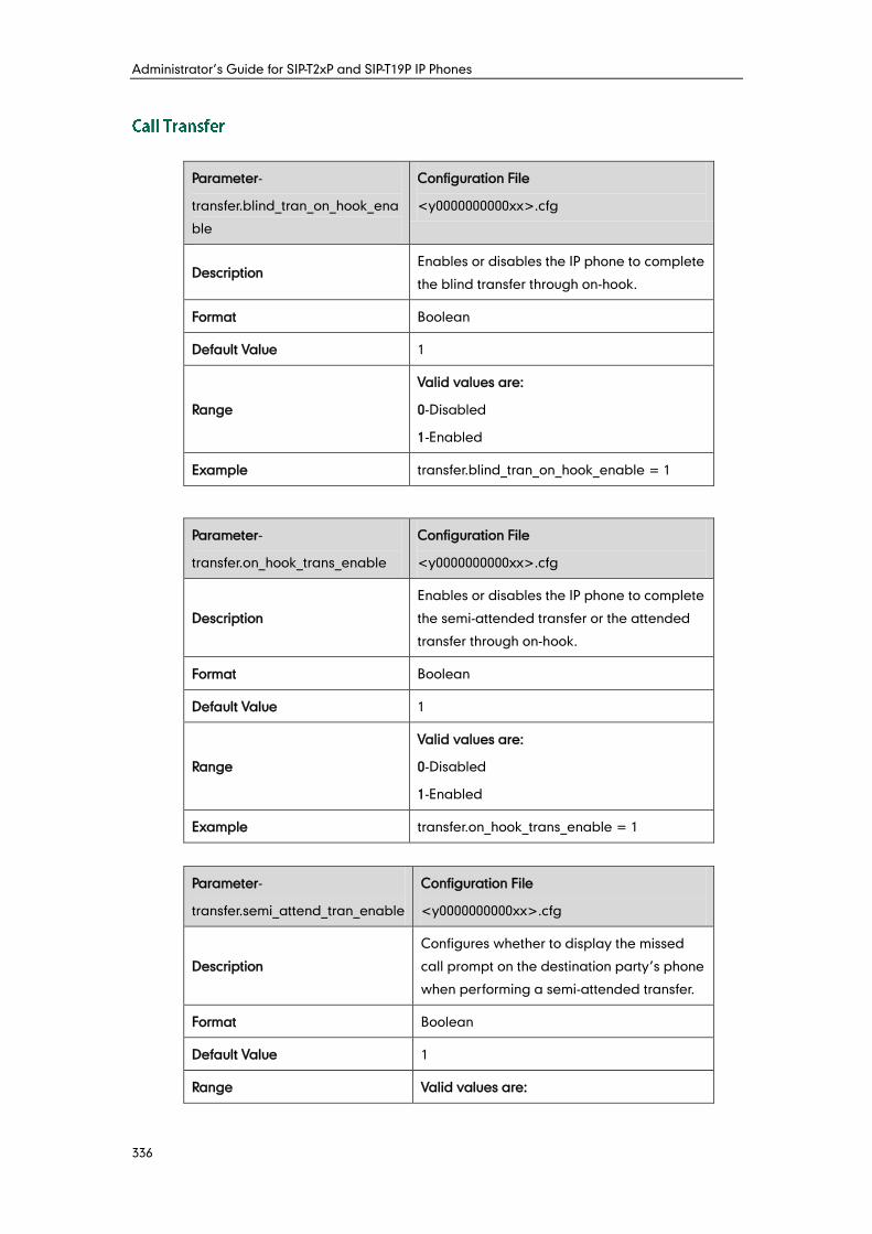
Administrator’s Guide for SIP-T2xP and SIP-T19P IP Phones
336
Parameter-
transfer.blind_tran_on_hook_ena
ble
Configuration File
<y0000000000xx>.cfg
Description Enables or disables the IP phone to complete
the blind transfer through on-hook.
Format Boolean
Default Value 1
Range
Valid values are:
0-Disabled
1-Enabled
Example transfer.blind_tran_on_hook_enable = 1
Parameter-
transfer.on_hook_trans_enable
Configuration File
<y0000000000xx>.cfg
Description
Enables or disables the IP phone to complete
the semi-attended transfer or the attended
transfer through on-hook.
Format Boolean
Default Value 1
Range
Valid values are:
0-Disabled
1-Enabled
Example transfer.on_hook_trans_enable = 1
Parameter-
transfer.semi_attend_tran_enable
Configuration File
<y0000000000xx>.cfg
Description
Configures whether to display the missed
call prompt on the destination party’s phone
when performing a semi-attended transfer.
Format Boolean
Default Value 1
Range Valid values are:
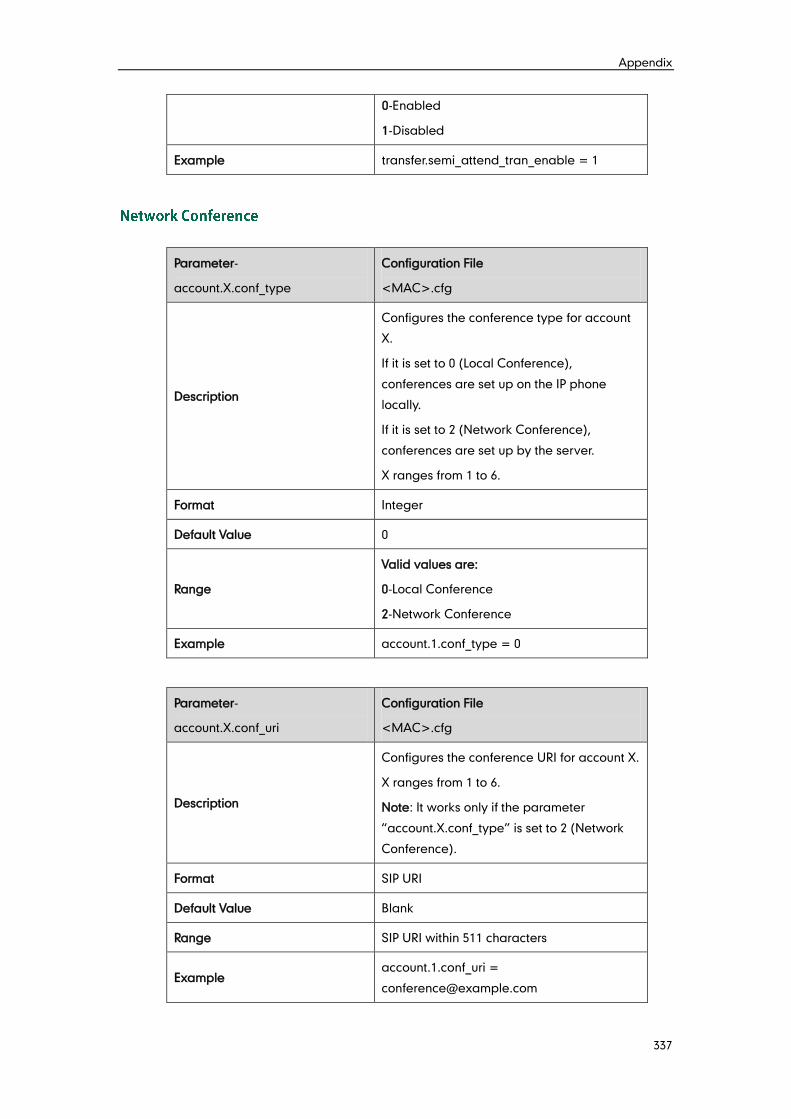
Appendix
337
0-Enabled
1-Disabled
Example transfer.semi_attend_tran_enable = 1
Parameter-
account.X.conf_type
Configuration File
<MAC>.cfg
Description
Configures the conference type for account
X.
If it is set to 0 (Local Conference),
conferences are set up on the IP phone
locally.
If it is set to 2 (Network Conference),
conferences are set up by the server.
X ranges from 1 to 6.
Format Integer
Default Value 0
Range
Valid values are:
0-Local Conference
2-Network Conference
Example account.1.conf_type = 0
Parameter-
account.X.conf_uri
Configuration File
<MAC>.cfg
Description
Configures the conference URI for account X.
X ranges from 1 to 6.
Note: It works only if the parameter
“account.X.conf_type” is set to 2 (Network
Conference).
Format SIP URI
Default Value Blank
Range SIP URI within 511 characters
Example account.1.conf_uri =
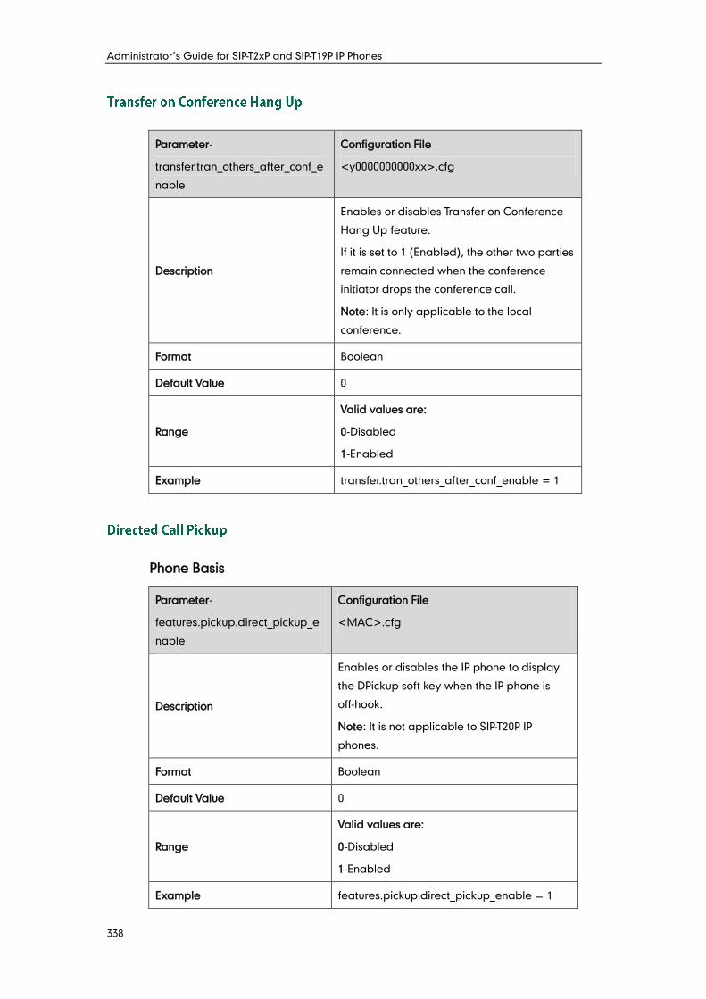
Administrator’s Guide for SIP-T2xP and SIP-T19P IP Phones
338
Parameter-
transfer.tran_others_after_conf_e
nable
Configuration File
<y0000000000xx>.cfg
Description
Enables or disables Transfer on Conference
Hang Up feature.
If it is set to 1 (Enabled), the other two parties
remain connected when the conference
initiator drops the conference call.
Note: It is only applicable to the local
conference.
Format Boolean
Default Value 0
Range
Valid values are:
0-Disabled
1-Enabled
Example transfer.tran_others_after_conf_enable = 1
Phone Basis
Parameter-
features.pickup.direct_pickup_e
nable
Configuration File
<MAC>.cfg
Description
Enables or disables the IP phone to display
the DPickup soft key when the IP phone is
off-hook.
Note: It is not applicable to SIP-T20P IP
phones.
Format Boolean
Default Value 0
Range
Valid values are:
0-Disabled
1-Enabled
Example features.pickup.direct_pickup_enable = 1
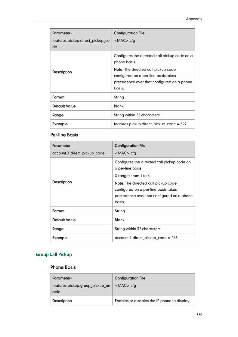
Appendix
339
Parameter-
features.pickup.direct_pickup_co
de
Configuration File
<MAC>.cfg
Description
Configures the directed call pickup code on a
phone basis.
Note: The directed call pickup code
configured on a per-line basis takes
precedence over that configured on a phone
basis.
Format String
Default Value Blank
Range String within 32 characters
Example features.pickup.direct_pickup_code = *97
Per-line Basis
Parameter-
account.X.direct_pickup_code
Configuration File
<MAC>.cfg
Description
Configures the directed call pickup code on
a per-line basis.
X ranges from 1 to 6.
Note: The directed call pickup code
configured on a per-line basis takes
precedence over that configured on a phone
basis.
Format String
Default Value Blank
Range String within 32 characters
Example account.1.direct_pickup_code = *68
Phone Basis
Parameter-
features.pickup.group_pickup_en
able
Configuration File
<MAC>.cfg
Description Enables or disables the IP phone to display
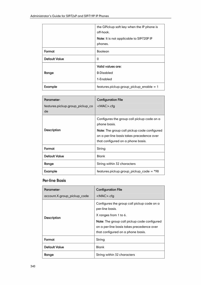
Administrator’s Guide for SIP-T2xP and SIP-T19P IP Phones
340
the GPickup soft key when the IP phone is
off-hook.
Note: It is not applicable to SIP-T20P IP
phones.
Format Boolean
Default Value 0
Range
Valid values are:
0-Disabled
1-Enabled
Example features.pickup.group_pickup_enable = 1
Parameter-
features.pickup.group_pickup_co
de
Configuration File
<MAC>.cfg
Description
Configures the group call pickup code on a
phone basis.
Note: The group call pickup code configured
on a per-line basis takes precedence over
that configured on a phone basis.
Format String
Default Value Blank
Range String within 32 characters
Example features.pickup.group_pickup_code = *98
Per-line Basis
Parameter-
account.X.group_pickup_code
Configuration File
<MAC>.cfg
Description
Configures the group call pickup code on a
per-line basis.
X ranges from 1 to 6.
Note: The group call pickup code configured
on a per-line basis takes precedence over
that configured on a phone basis.
Format String
Default Value Blank
Range String within 32 characters
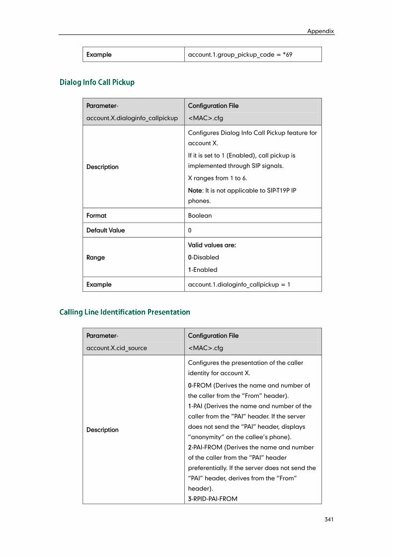
Appendix
341
Example account.1.group_pickup_code = *69
Parameter-
account.X.dialoginfo_callpickup
Configuration File
<MAC>.cfg
Description
Configures Dialog Info Call Pickup feature for
account X.
If it is set to 1 (Enabled), call pickup is
implemented through SIP signals.
X ranges from 1 to 6.
Note: It is not applicable to SIP-T19P IP
phones.
Format Boolean
Default Value 0
Range
Valid values are:
0-Disabled
1-Enabled
Example account.1.dialoginfo_callpickup = 1
Parameter-
account.X.cid_source
Configuration File
<MAC>.cfg
Description
Configures the presentation of the caller
identity for account X.
0-FROM (Derives the name and number of
the caller from the “From” header).
1-PAI (Derives the name and number of the
caller from the “PAI” header. If the server
does not send the “PAI” header, displays
“anonymity” on the callee’s phone).
2-PAI-FROM (Derives the name and number
of the caller from the “PAI” header
preferentially. If the server does not send the
“PAI” header, derives from the “From”
header).
3-RPID-PAI-FROM
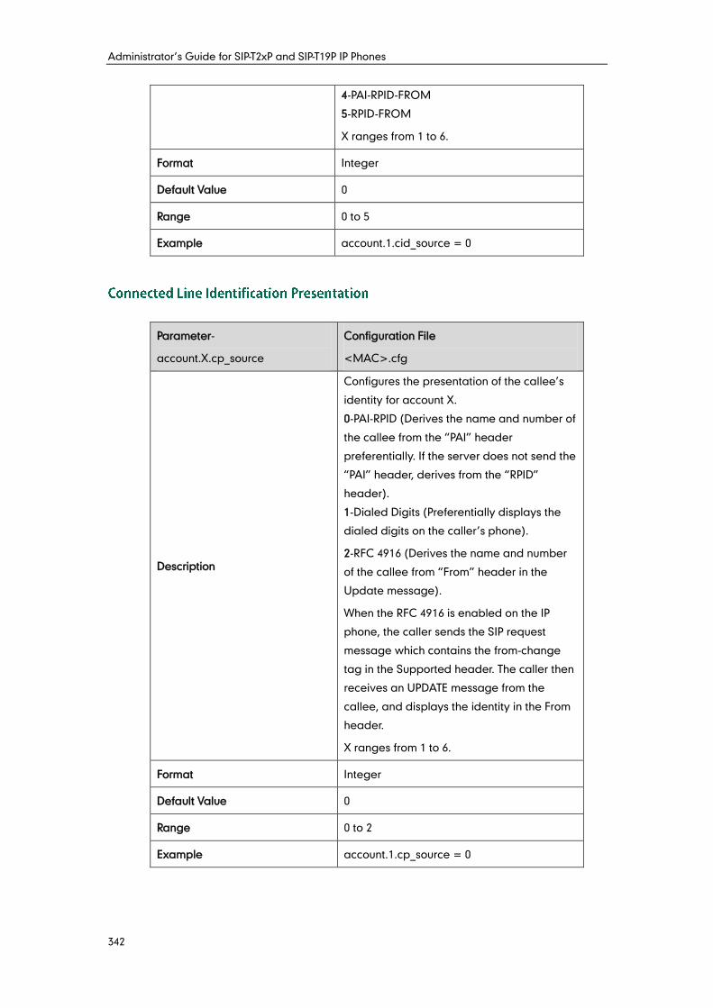
Administrator’s Guide for SIP-T2xP and SIP-T19P IP Phones
342
4-PAI-RPID-FROM
5-RPID-FROM
X ranges from 1 to 6.
Format Integer
Default Value 0
Range 0 to 5
Example account.1.cid_source = 0
Parameter-
account.X.cp_source
Configuration File
<MAC>.cfg
Description
Configures the presentation of the callee’s
identity for account X.
0-PAI-RPID (Derives the name and number of
the callee from the “PAI” header
preferentially. If the server does not send the
“PAI” header, derives from the “RPID”
header).
1-Dialed Digits (Preferentially displays the
dialed digits on the caller’s phone).
2-RFC 4916 (Derives the name and number
of the callee from “From” header in the
Update message).
When the RFC 4916 is enabled on the IP
phone, the caller sends the SIP request
message which contains the from-change
tag in the Supported header. The caller then
receives an UPDATE message from the
callee, and displays the identity in the From
header.
X ranges from 1 to 6.
Format Integer
Default Value 0
Range 0 to 2
Example account.1.cp_source = 0
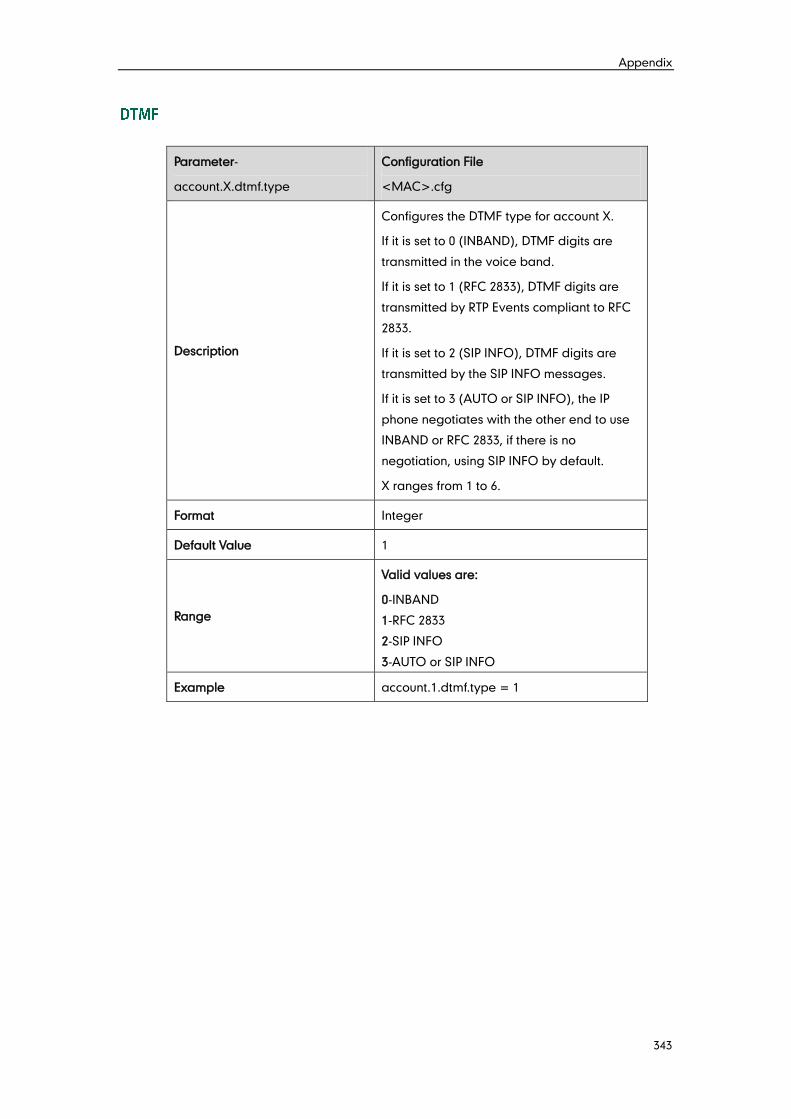
Appendix
343
Parameter-
account.X.dtmf.type
Configuration File
<MAC>.cfg
Description
Configures the DTMF type for account X.
If it is set to 0 (INBAND), DTMF digits are
transmitted in the voice band.
If it is set to 1 (RFC 2833), DTMF digits are
transmitted by RTP Events compliant to RFC
2833.
If it is set to 2 (SIP INFO), DTMF digits are
transmitted by the SIP INFO messages.
If it is set to 3 (AUTO or SIP INFO), the IP
phone negotiates with the other end to use
INBAND or RFC 2833, if there is no
negotiation, using SIP INFO by default.
X ranges from 1 to 6.
Format Integer
Default Value 1
Range
Valid values are:
0-INBAND
1-RFC 2833
2-SIP INFO
3-AUTO or SIP INFO
Example account.1.dtmf.type = 1
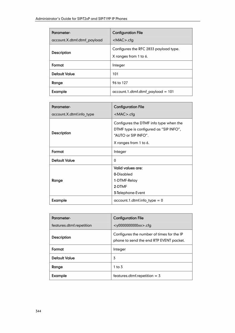
Administrator’s Guide for SIP-T2xP and SIP-T19P IP Phones
344
Parameter-
account.X.dtmf.dtmf_payload
Configuration File
<MAC>.cfg
Description Configures the RFC 2833 payload type.
X ranges from 1 to 6.
Format Integer
Default Value 101
Range 96 to 127
Example account.1.dtmf.dtmf_payload = 101
Parameter-
account.X.dtmf.info_type
Configuration File
<MAC>.cfg
Description
Configures the DTMF info type when the
DTMF type is configured as “SIP INFO”,
“AUTO or SIP INFO”.
X ranges from 1 to 6.
Format Integer
Default Value 0
Range
Valid values are:
0-Disabled
1-DTMF-Relay
2-DTMF
3-Telephone-Event
Example account.1.dtmf.info_type = 0
Parameter-
features.dtmf.repetition
Configuration File
<y0000000000xx>.cfg
Description Configures the number of times for the IP
phone to send the end RTP EVENT packet.
Format Integer
Default Value 3
Range 1 to 3
Example features.dtmf.repetition = 3
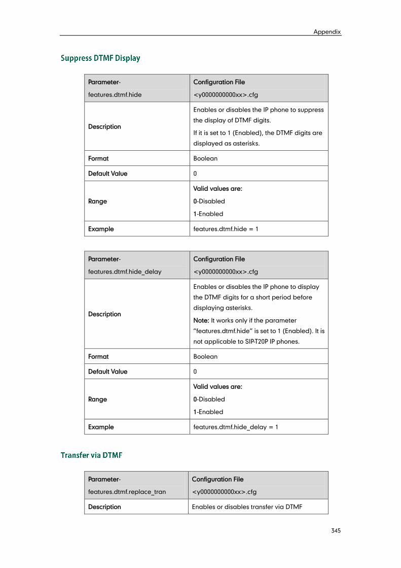
Appendix
345
Parameter-
features.dtmf.hide
Configuration File
<y0000000000xx>.cfg
Description
Enables or disables the IP phone to suppress
the display of DTMF digits.
If it is set to 1 (Enabled), the DTMF digits are
displayed as asterisks.
Format Boolean
Default Value 0
Range
Valid values are:
0-Disabled
1-Enabled
Example features.dtmf.hide = 1
Parameter-
features.dtmf.hide_delay
Configuration File
<y0000000000xx>.cfg
Description
Enables or disables the IP phone to display
the DTMF digits for a short period before
displaying asterisks.
Note: It works only if the parameter
“features.dtmf.hide” is set to 1 (Enabled). It is
not applicable to SIP-T20P IP phones.
Format Boolean
Default Value 0
Range
Valid values are:
0-Disabled
1-Enabled
Example features.dtmf.hide_delay = 1
Parameter-
features.dtmf.replace_tran
Configuration File
<y0000000000xx>.cfg
Description Enables or disables transfer via DTMF
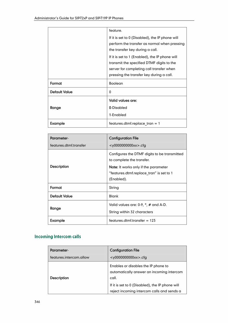
Administrator’s Guide for SIP-T2xP and SIP-T19P IP Phones
346
feature.
If it is set to 0 (Disabled), the IP phone will
perform the transfer as normal when pressing
the transfer key during a call.
If it is set to 1 (Enabled), the IP phone will
transmit the specified DTMF digits to the
server for completing call transfer when
pressing the transfer key during a call.
Format Boolean
Default Value 0
Range
Valid values are:
0-Disabled
1-Enabled
Example features.dtmf.replace_tran = 1
Parameter-
features.dtmf.transfer
Configuration File
<y0000000000xx>.cfg
Description
Configures the DTMF digits to be transmitted
to complete the transfer.
Note: It works only if the parameter
“features.dtmf.replace_tran” is set to 1
(Enabled).
Format String
Default Value Blank
Range Valid values are: 0-9, *, # and A-D.
String within 32 characters
Example features.dtmf.transfer = 123
Parameter-
features.intercom.allow
Configuration File
<y0000000000xx>.cfg
Description
Enables or disables the IP phone to
automatically answer an incoming intercom
call.
If it is set to 0 (Disabled), the IP phone will
reject incoming intercom calls and sends a
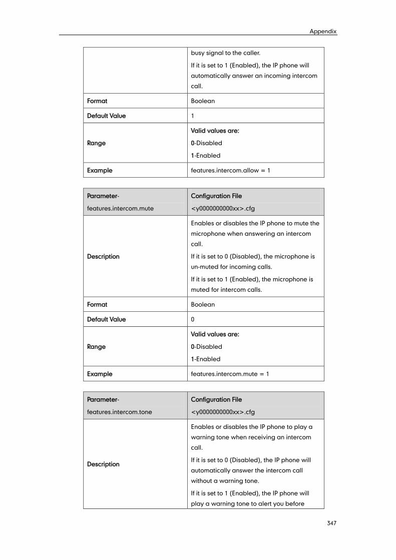
Appendix
347
busy signal to the caller.
If it is set to 1 (Enabled), the IP phone will
automatically answer an incoming intercom
call.
Format Boolean
Default Value 1
Range
Valid values are:
0-Disabled
1-Enabled
Example features.intercom.allow = 1
Parameter-
features.intercom.mute
Configuration File
<y0000000000xx>.cfg
Description
Enables or disables the IP phone to mute the
microphone when answering an intercom
call.
If it is set to 0 (Disabled), the microphone is
un-muted for incoming calls.
If it is set to 1 (Enabled), the microphone is
muted for intercom calls.
Format Boolean
Default Value 0
Range
Valid values are:
0-Disabled
1-Enabled
Example features.intercom.mute = 1
Parameter-
features.intercom.tone
Configuration File
<y0000000000xx>.cfg
Description
Enables or disables the IP phone to play a
warning tone when receiving an intercom
call.
If it is set to 0 (Disabled), the IP phone will
automatically answer the intercom call
without a warning tone.
If it is set to 1 (Enabled), the IP phone will
play a warning tone to alert you before
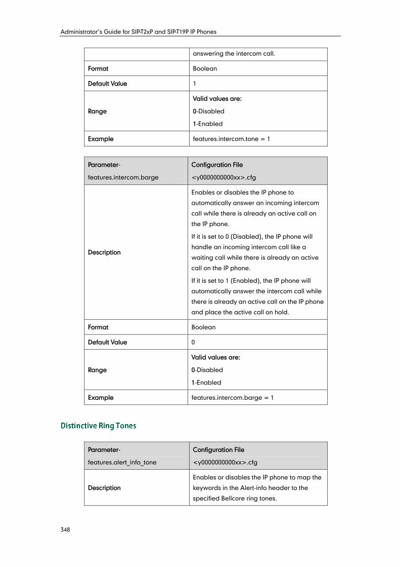
Administrator’s Guide for SIP-T2xP and SIP-T19P IP Phones
348
answering the intercom call.
Format Boolean
Default Value 1
Range
Valid values are:
0-Disabled
1-Enabled
Example features.intercom.tone = 1
Parameter-
features.intercom.barge
Configuration File
<y0000000000xx>.cfg
Description
Enables or disables the IP phone to
automatically answer an incoming intercom
call while there is already an active call on
the IP phone.
If it is set to 0 (Disabled), the IP phone will
handle an incoming intercom call like a
waiting call while there is already an active
call on the IP phone.
If it is set to 1 (Enabled), the IP phone will
automatically answer the intercom call while
there is already an active call on the IP phone
and place the active call on hold.
Format Boolean
Default Value 0
Range
Valid values are:
0-Disabled
1-Enabled
Example features.intercom.barge = 1
Parameter-
features.alert_info_tone
Configuration File
<y0000000000xx>.cfg
Description
Enables or disables the IP phone to map the
keywords in the Alert-info header to the
specified Bellcore ring tones.
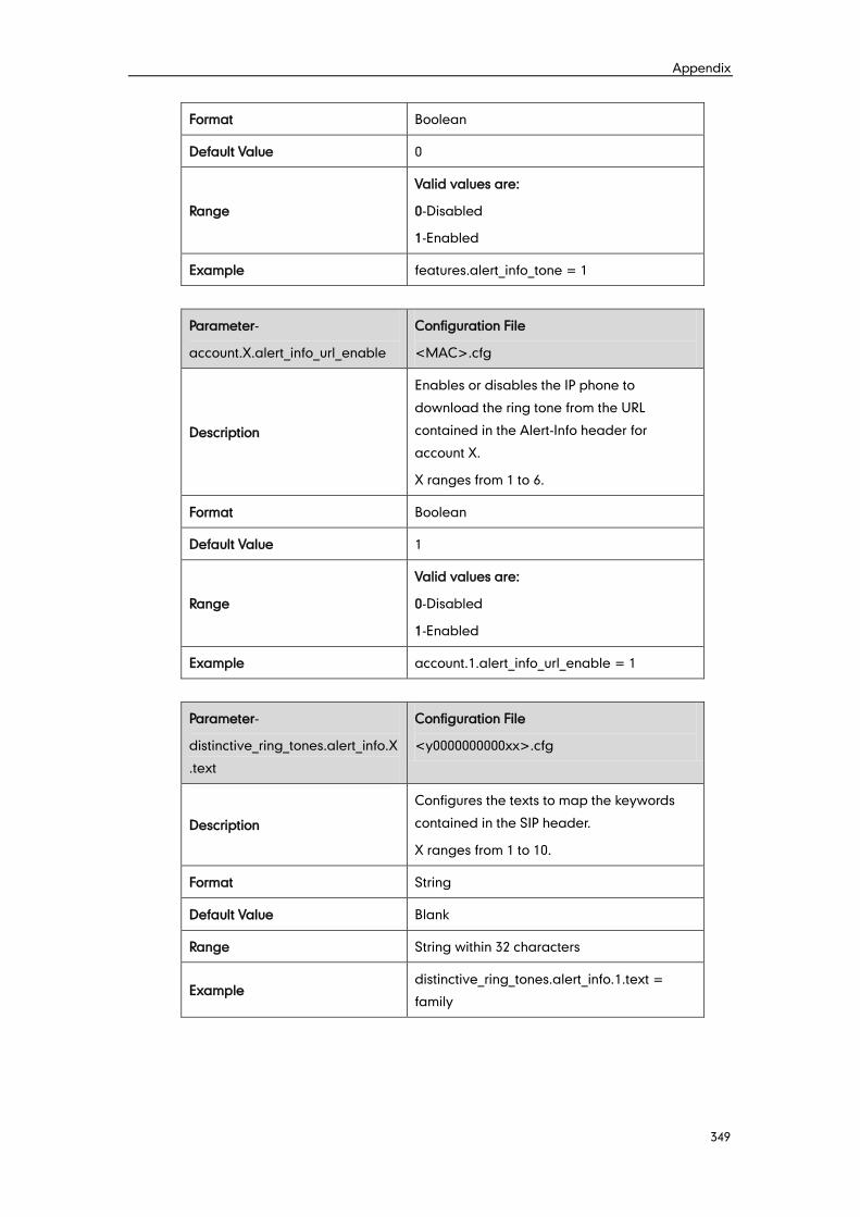
Appendix
349
Format Boolean
Default Value 0
Range
Valid values are:
0-Disabled
1-Enabled
Example features.alert_info_tone = 1
Parameter-
account.X.alert_info_url_enable
Configuration File
<MAC>.cfg
Description
Enables or disables the IP phone to
download the ring tone from the URL
contained in the Alert-Info header for
account X.
X ranges from 1 to 6.
Format Boolean
Default Value 1
Range
Valid values are:
0-Disabled
1-Enabled
Example account.1.alert_info_url_enable = 1
Parameter-
distinctive_ring_tones.alert_info.X
.text
Configuration File
<y0000000000xx>.cfg
Description
Configures the texts to map the keywords
contained in the SIP header.
X ranges from 1 to 10.
Format String
Default Value Blank
Range String within 32 characters
Example distinctive_ring_tones.alert_info.1.text =
family
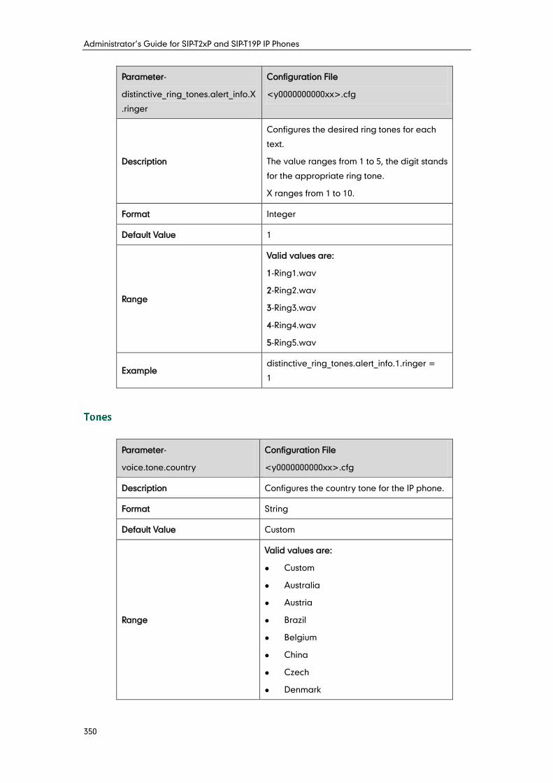
Administrator’s Guide for SIP-T2xP and SIP-T19P IP Phones
350
Parameter-
distinctive_ring_tones.alert_info.X
.ringer
Configuration File
<y0000000000xx>.cfg
Description
Configures the desired ring tones for each
text.
The value ranges from 1 to 5, the digit stands
for the appropriate ring tone.
X ranges from 1 to 10.
Format Integer
Default Value 1
Range
Valid values are:
1-Ring1.wav
2-Ring2.wav
3-Ring3.wav
4-Ring4.wav
5-Ring5.wav
Example distinctive_ring_tones.alert_info.1.ringer =
1
Parameter-
voice.tone.country
Configuration File
<y0000000000xx>.cfg
Description Configures the country tone for the IP phone.
Format String
Default Value Custom
Range
Valid values are:
Custom
Australia
Austria
Brazil
Belgium
China
Czech
Denmark
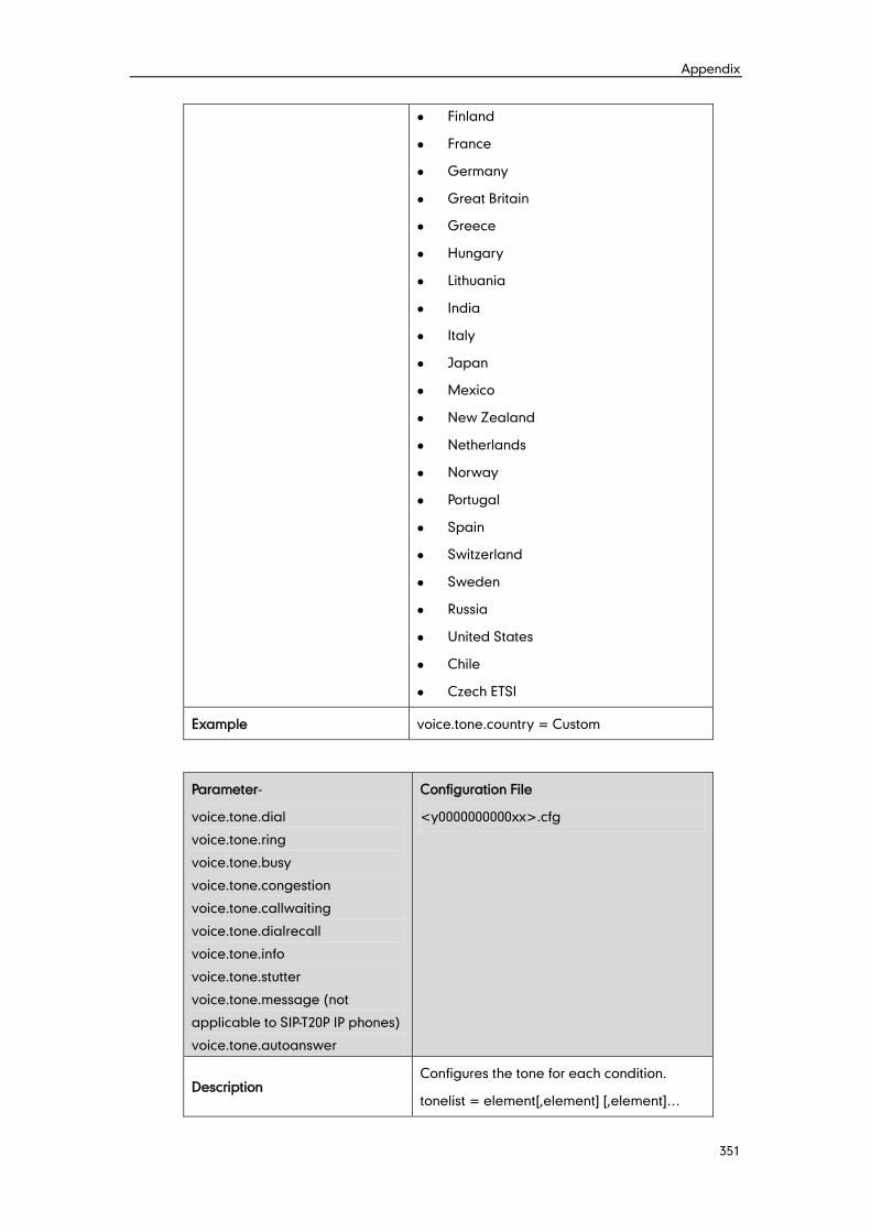
Appendix
351
Finland
France
Germany
Great Britain
Greece
Hungary
Lithuania
India
Italy
Japan
Mexico
New Zealand
Netherlands
Norway
Portugal
Spain
Switzerland
Sweden
Russia
United States
Chile
Czech ETSI
Example voice.tone.country = Custom
Parameter-
voice.tone.dial
voice.tone.ring
voice.tone.busy
voice.tone.congestion
voice.tone.callwaiting
voice.tone.dialrecall
voice.tone.info
voice.tone.stutter
voice.tone.message (not
applicable to SIP-T20P IP phones)
voice.tone.autoanswer
Configuration File
<y0000000000xx>.cfg
Description Configures the tone for each condition.
tonelist = element[,element] [,element]…

Administrator’s Guide for SIP-T2xP and SIP-T19P IP Phones
352
Where
element = [!]Freq1[+Freq2][+Freq3][+Freq4]
/Duration
Freq: the frequency of the tone (ranges from
200 to 7000 Hz). If it is set to 0 (0Hz), it means
the tone is not played. A tone is comprised of
at most four different frequencies.
Duration: the time duration (in milliseconds,
ranges from 0 to 30000ms) of the ring tone.
You can configure at most eight different
tones for one condition, and separate tones
by commas (e.g., 250/200, !0/1000,
200+300/500, 600+700+800+1000/2000). The
exclamation point (!) can be added
optionally, which means these tones are only
played once.
Note: It works only if the parameter
“voice.tone.country” is set to Custom.
Format Refer to the introduction above
Default Value Blank
Range Not Applicable
Example voice.tone.dial = 800+200/1000, 0/100,
500/1200, 500+600+950+1500/5000
Parameter-
remote_phonebook.data.X.url
Configuration File
<y0000000000xx>.cfg
Description
Configures the access URL of the remote
XML phone book.
X ranges from 1 to 5.
Note: It is not applicable to SIP-T20P IP
phones.
Format URL
Default Value Blank
Range String within 511 characters
Example remote_phonebook.data.1.url =
http://192.168.1.20/phonebook.xml
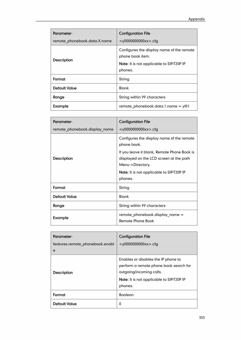
Appendix
353
Parameter-
remote_phonebook.data.X.name
Configuration File
<y0000000000xx>.cfg
Description
Configures the display name of the remote
phone book item.
Note: It is not applicable to SIP-T20P IP
phones.
Format String
Default Value Blank
Range String within 99 characters
Example remote_phonebook.data.1.name = yl01
Parameter-
remote_phonebook.display_name
Configuration File
<y0000000000xx>.cfg
Description
Configures the display name of the remote
phone book.
If you leave it blank, Remote Phone Book is
displayed on the LCD screen at the path
Menu->Directory.
Note: It is not applicable to SIP-T20P IP
phones.
Format String
Default Value Blank
Range String within 99 characters
Example remote_phonebook.display_name =
Remote Phone Book
Parameter-
features.remote_phonebook.enabl
e
Configuration File
<y0000000000xx>.cfg
Description
Enables or disables the IP phone to
perform a remote phone book search for
outgoing/incoming calls.
Note: It is not applicable to SIP-T20P IP
phones.
Format Boolean
Default Value 0
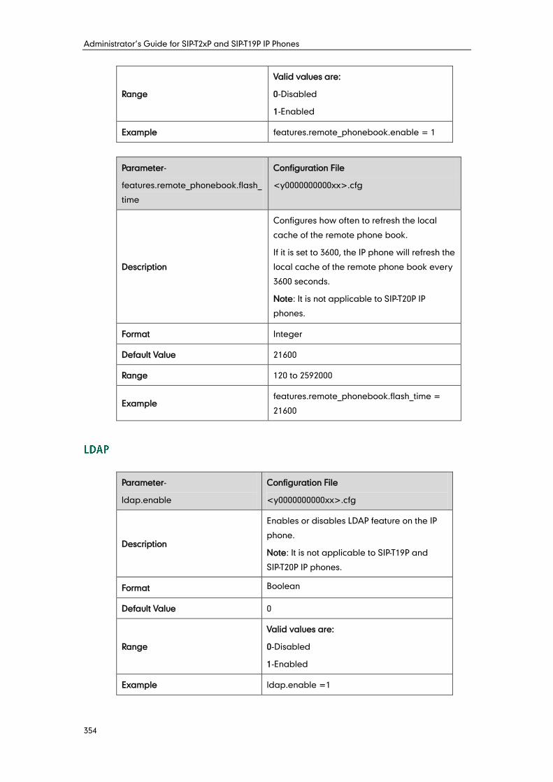
Administrator’s Guide for SIP-T2xP and SIP-T19P IP Phones
354
Range
Valid values are:
0-Disabled
1-Enabled
Example features.remote_phonebook.enable = 1
Parameter-
features.remote_phonebook.flash_
time
Configuration File
<y0000000000xx>.cfg
Description
Configures how often to refresh the local
cache of the remote phone book.
If it is set to 3600, the IP phone will refresh the
local cache of the remote phone book every
3600 seconds.
Note: It is not applicable to SIP-T20P IP
phones.
Format Integer
Default Value 21600
Range 120 to 2592000
Example features.remote_phonebook.flash_time =
21600
Parameter-
ldap.enable
Configuration File
<y0000000000xx>.cfg
Description
Enables or disables LDAP feature on the IP
phone.
Note: It is not applicable to SIP-T19P and
SIP-T20P IP phones.
Format Boolean
Default Value 0
Range
Valid values are:
0-Disabled
1-Enabled
Example ldap.enable =1
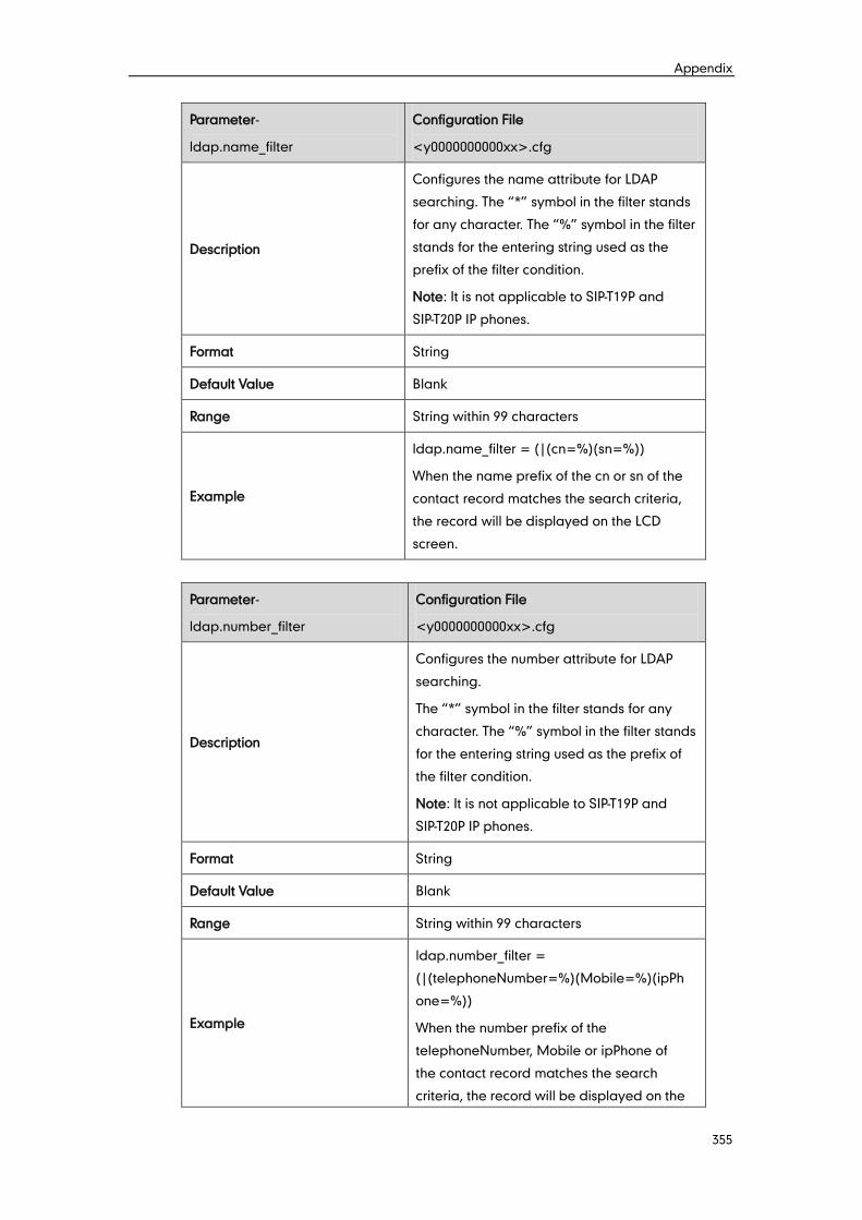
Appendix
355
Parameter-
ldap.name_filter
Configuration File
<y0000000000xx>.cfg
Description
Configures the name attribute for LDAP
searching. The “*” symbol in the filter stands
for any character. The “%” symbol in the filter
stands for the entering string used as the
prefix of the filter condition.
Note: It is not applicable to SIP-T19P and
SIP-T20P IP phones.
Format String
Default Value Blank
Range String within 99 characters
Example
ldap.name_filter = (|(cn=%)(sn=%))
When the name prefix of the cn or sn of the
contact record matches the search criteria,
the record will be displayed on the LCD
screen.
Parameter-
ldap.number_filter
Configuration File
<y0000000000xx>.cfg
Description
Configures the number attribute for LDAP
searching.
The “*” symbol in the filter stands for any
character. The “%” symbol in the filter stands
for the entering string used as the prefix of
the filter condition.
Note: It is not applicable to SIP-T19P and
SIP-T20P IP phones.
Format String
Default Value Blank
Range String within 99 characters
Example
ldap.number_filter =
(|(telephoneNumber=%)(Mobile=%)(ipPh
one=%))
When the number prefix of the
telephoneNumber, Mobile or ipPhone of
the contact record matches the search
criteria, the record will be displayed on the
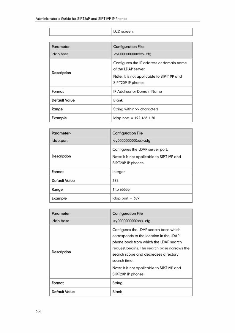
Administrator’s Guide for SIP-T2xP and SIP-T19P IP Phones
356
LCD screen.
Parameter-
ldap.host
Configuration File
<y0000000000xx>.cfg
Description
Configures the IP address or domain name
of the LDAP server.
Note: It is not applicable to SIP-T19P and
SIP-T20P IP phones.
Format IP Address or Domain Name
Default Value Blank
Range String within 99 characters
Example ldap.host = 192.168.1.20
Parameter-
ldap.port
Configuration File
<y0000000000xx>.cfg
Description
Configures the LDAP server port.
Note: It is not applicable to SIP-T19P and
SIP-T20P IP phones.
Format Integer
Default Value 389
Range 1 to 65535
Example ldap.port = 389
Parameter-
ldap.base
Configuration File
<y0000000000xx>.cfg
Description
Configures the LDAP search base which
corresponds to the location in the LDAP
phone book from which the LDAP search
request begins. The search base narrows the
search scope and decreases directory
search time.
Note: It is not applicable to SIP-T19P and
SIP-T20P IP phones.
Format String
Default Value Blank
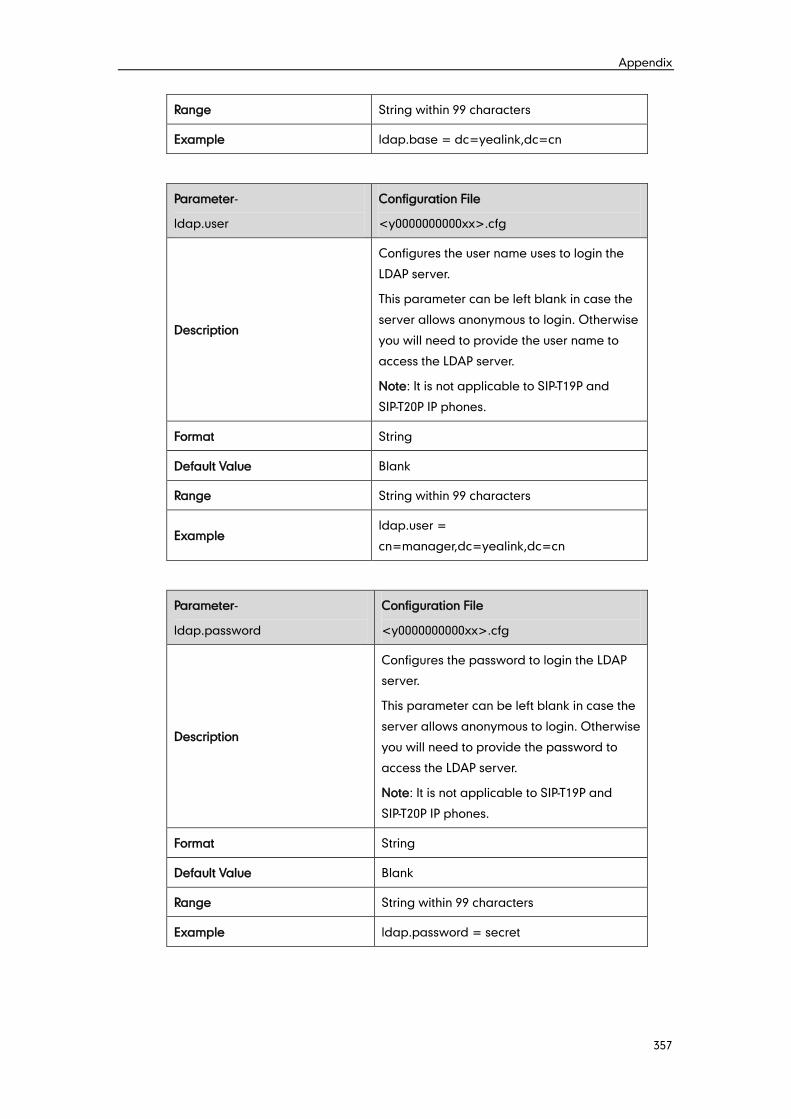
Appendix
357
Range String within 99 characters
Example ldap.base = dc=yealink,dc=cn
Parameter-
ldap.user
Configuration File
<y0000000000xx>.cfg
Description
Configures the user name uses to login the
LDAP server.
This parameter can be left blank in case the
server allows anonymous to login. Otherwise
you will need to provide the user name to
access the LDAP server.
Note: It is not applicable to SIP-T19P and
SIP-T20P IP phones.
Format String
Default Value Blank
Range String within 99 characters
Example ldap.user =
cn=manager,dc=yealink,dc=cn
Parameter-
ldap.password
Configuration File
<y0000000000xx>.cfg
Description
Configures the password to login the LDAP
server.
This parameter can be left blank in case the
server allows anonymous to login. Otherwise
you will need to provide the password to
access the LDAP server.
Note: It is not applicable to SIP-T19P and
SIP-T20P IP phones.
Format String
Default Value Blank
Range String within 99 characters
Example ldap.password = secret
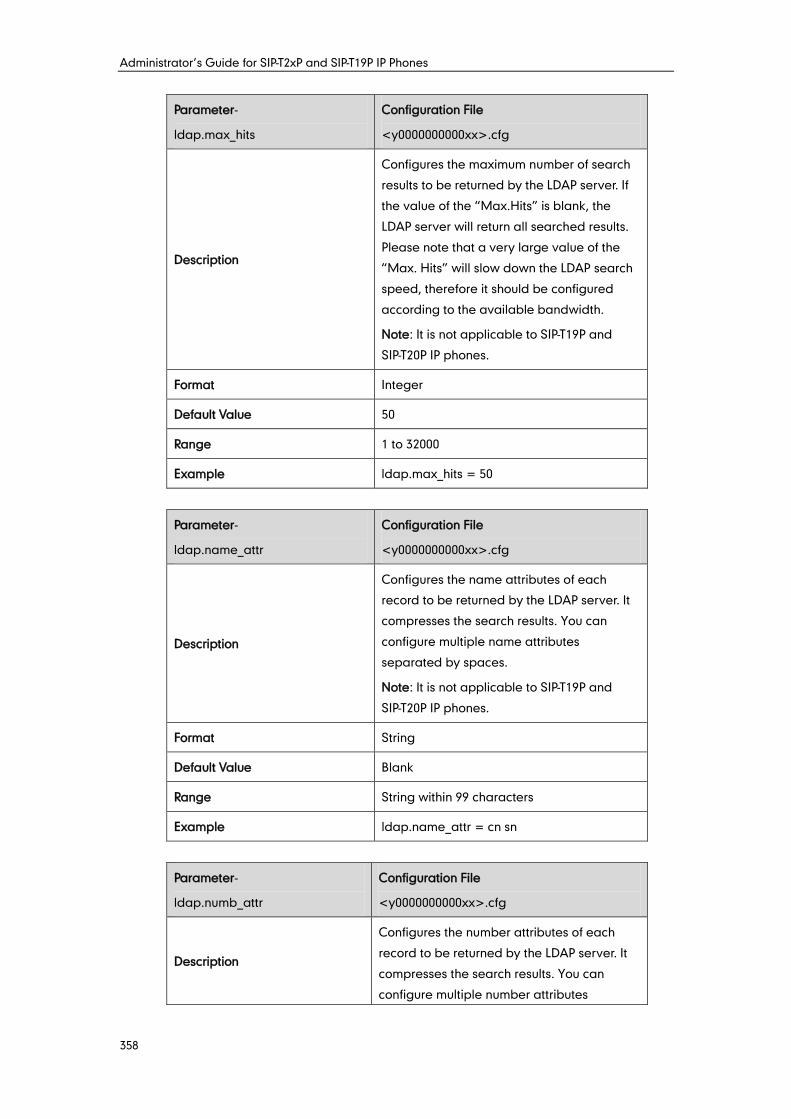
Administrator’s Guide for SIP-T2xP and SIP-T19P IP Phones
358
Parameter-
ldap.max_hits
Configuration File
<y0000000000xx>.cfg
Description
Configures the maximum number of search
results to be returned by the LDAP server. If
the value of the “Max.Hits” is blank, the
LDAP server will return all searched results.
Please note that a very large value of the
“Max. Hits” will slow down the LDAP search
speed, therefore it should be configured
according to the available bandwidth.
Note: It is not applicable to SIP-T19P and
SIP-T20P IP phones.
Format Integer
Default Value 50
Range 1 to 32000
Example ldap.max_hits = 50
Parameter-
ldap.name_attr
Configuration File
<y0000000000xx>.cfg
Description
Configures the name attributes of each
record to be returned by the LDAP server. It
compresses the search results. You can
configure multiple name attributes
separated by spaces.
Note: It is not applicable to SIP-T19P and
SIP-T20P IP phones.
Format String
Default Value Blank
Range String within 99 characters
Example ldap.name_attr = cn sn
Parameter-
ldap.numb_attr
Configuration File
<y0000000000xx>.cfg
Description
Configures the number attributes of each
record to be returned by the LDAP server. It
compresses the search results. You can
configure multiple number attributes
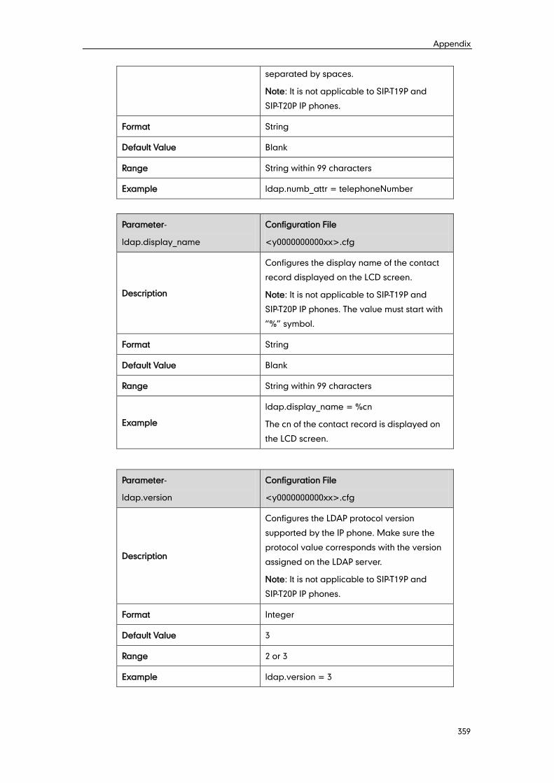
Appendix
359
separated by spaces.
Note: It is not applicable to SIP-T19P and
SIP-T20P IP phones.
Format String
Default Value Blank
Range String within 99 characters
Example ldap.numb_attr = telephoneNumber
Parameter-
ldap.display_name
Configuration File
<y0000000000xx>.cfg
Description
Configures the display name of the contact
record displayed on the LCD screen.
Note: It is not applicable to SIP-T19P and
SIP-T20P IP phones. The value must start with
“%” symbol.
Format String
Default Value Blank
Range String within 99 characters
Example
ldap.display_name = %cn
The cn of the contact record is displayed on
the LCD screen.
Parameter-
ldap.version
Configuration File
<y0000000000xx>.cfg
Description
Configures the LDAP protocol version
supported by the IP phone. Make sure the
protocol value corresponds with the version
assigned on the LDAP server.
Note: It is not applicable to SIP-T19P and
SIP-T20P IP phones.
Format Integer
Default Value 3
Range 2 or 3
Example ldap.version = 3

Administrator’s Guide for SIP-T2xP and SIP-T19P IP Phones
360
Parameter-
ldap.call_in_lookup
Configuration File
<y0000000000xx>.cfg
Description
Enables or disables the IP phone to perform
an LDAP search when receiving an incoming
call.
Note: It is not applicable to SIP-T19P and
SIP-T20P IP phones.
Format Boolean
Default Value 0
Range
Valid values are:
0-Disabled
1-Enabled
Example ldap.call_in_lookup = 1
Parameter-
ldap.ldap_sort
Configuration File
<y0000000000xx>.cfg
Description
Enables or disables the IP phone to sort the
search results in alphabetical order or
numerical order.
Note: It is not applicable to SIP-T19P and
SIP-T20P IP phones.
Format Boolean
Default Value 0
Range
Valid values are:
0-Disabled
1-Enabled
Example ldap.ldap_sort = 1
Visual and Audio Alert for BLF Pickup
Parameter-
features.pickup.blf_visual_enabl
e
Configuration File
<MAC>.cfg
Description Enables or disables the IP phone to display a
visual prompt when the monitored user
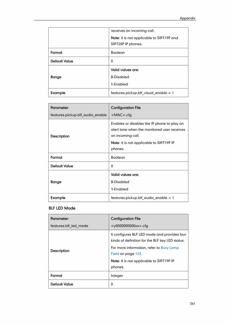
Appendix
361
receives an incoming call.
Note: It is not applicable to SIP-T19P and
SIP-T20P IP phones.
Format Boolean
Default Value 0
Range
Valid values are:
0-Disabled
1-Enabled
Example features.pickup.blf_visual_enable = 1
Parameter-
features.pickup.blf_audio_enable
Configuration File
<MAC>.cfg
Description
Enables or disables the IP phone to play an
alert tone when the monitored user receives
an incoming call.
Note: It is not applicable to SIP-T19P IP
phones.
Format Boolean
Default Value 0
Range
Valid values are:
0-Disabled
1-Enabled
Example features.pickup.blf_audio_enable = 1
BLF LED Mode
Parameter-
features.blf_led_mode
Configuration File
<y0000000000xx>.cfg
Description
It configures BLF LED mode and provides four
kinds of definition for the BLF key LED status.
For more information, refer to Busy Lamp
Field on page 153.
Note: It is not applicable to SIP-T19P IP
phones.
Format Integer
Default Value 0
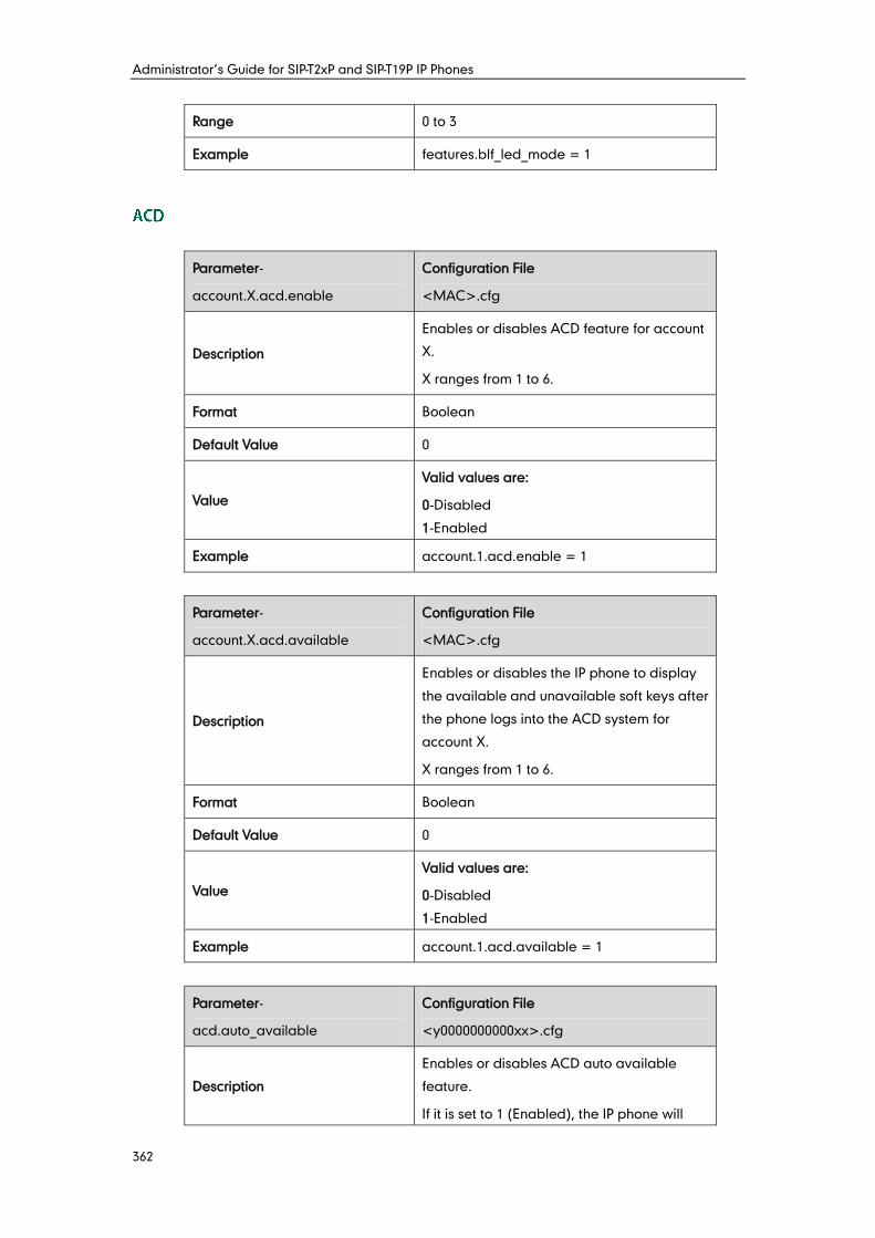
Administrator’s Guide for SIP-T2xP and SIP-T19P IP Phones
362
Range 0 to 3
Example features.blf_led_mode = 1
Parameter-
account.X.acd.enable
Configuration File
<MAC>.cfg
Description
Enables or disables ACD feature for account
X.
X ranges from 1 to 6.
Format Boolean
Default Value 0
Value
Valid values are:
0-Disabled
1-Enabled
Example account.1.acd.enable = 1
Parameter-
account.X.acd.available
Configuration File
<MAC>.cfg
Description
Enables or disables the IP phone to display
the available and unavailable soft keys after
the phone logs into the ACD system for
account X.
X ranges from 1 to 6.
Format Boolean
Default Value 0
Value
Valid values are:
0-Disabled
1-Enabled
Example account.1.acd.available = 1
Parameter-
acd.auto_available
Configuration File
<y0000000000xx>.cfg
Description
Enables or disables ACD auto available
feature.
If it is set to 1 (Enabled), the IP phone will

Appendix
363
automatically change the phone status to
available.
Format Boolean
Default Value 0
Value
Valid values are:
0-Disabled
1-Enabled
Example acd.auto_available = 1
Parameter-
acd.auto_available_timer
Configuration File
<y0000000000xx>.cfg
Description
Configures the length of time (in seconds)
before the IP phone state is automatically
changed to available.
Note: It works only if the parameter
“acd.auto_available” is set to 1 (Enabled).
Format Integer
Default Value 60
Value 0 to 120
Example acd.auto_available_timer = 60
Parameter-
account.X.subscribe_mwi
Configuration File
<MAC>.cfg
Description
Enables or disables the IP phone to
subscribe the message waiting indicator to
the account for account X.
If it is set to 1 (Enabled), the IP phone will
send a SUBSCRIBE message to the server
for message-summary updates.
X ranges from 1 to 6.
Format Boolean
Default Value 0
Value Valid values are:
0-Disabled
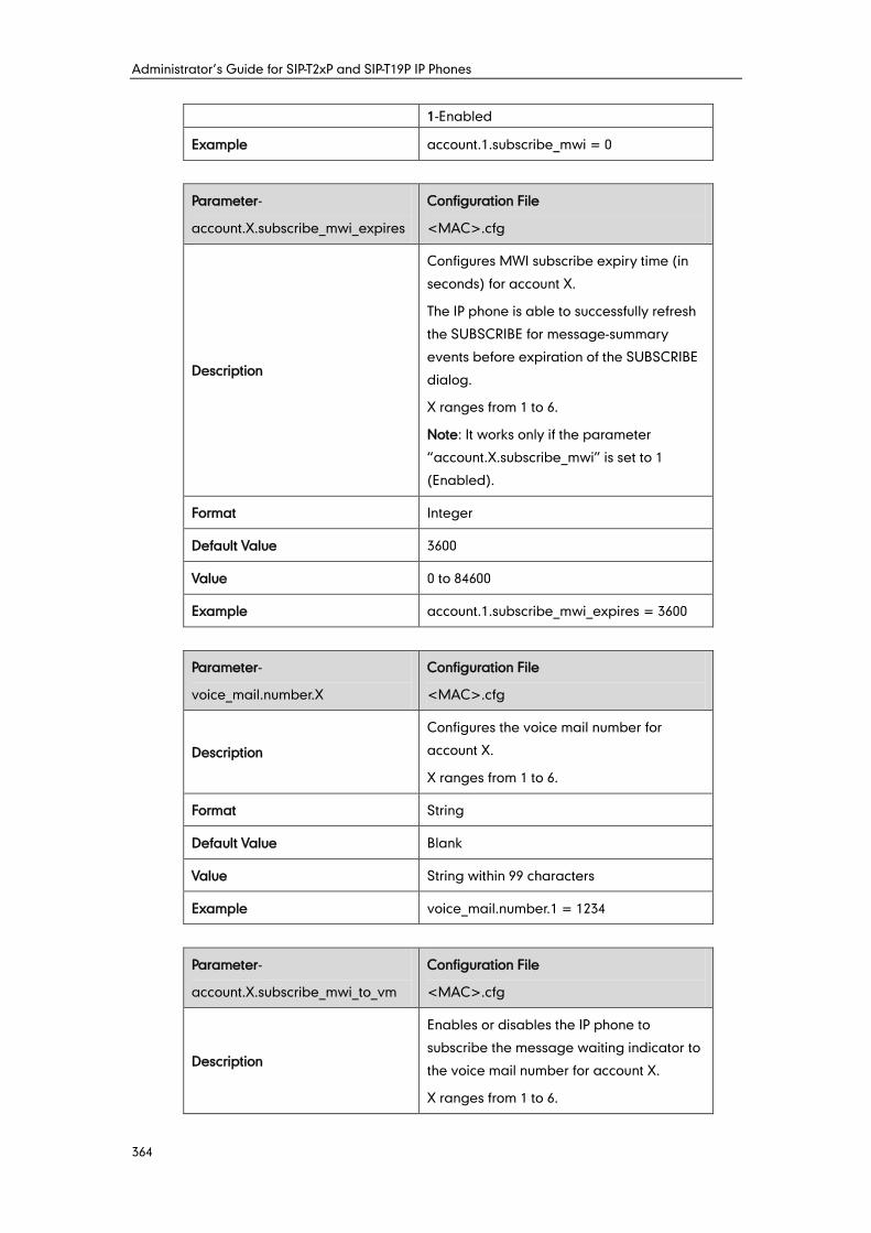
Administrator’s Guide for SIP-T2xP and SIP-T19P IP Phones
364
1-Enabled
Example account.1.subscribe_mwi = 0
Parameter-
account.X.subscribe_mwi_expires
Configuration File
<MAC>.cfg
Description
Configures MWI subscribe expiry time (in
seconds) for account X.
The IP phone is able to successfully refresh
the SUBSCRIBE for message-summary
events before expiration of the SUBSCRIBE
dialog.
X ranges from 1 to 6.
Note: It works only if the parameter
“account.X.subscribe_mwi” is set to 1
(Enabled).
Format Integer
Default Value 3600
Value 0 to 84600
Example account.1.subscribe_mwi_expires = 3600
Parameter-
voice_mail.number.X
Configuration File
<MAC>.cfg
Description
Configures the voice mail number for
account X.
X ranges from 1 to 6.
Format String
Default Value Blank
Value String within 99 characters
Example voice_mail.number.1 = 1234
Parameter-
account.X.subscribe_mwi_to_vm
Configuration File
<MAC>.cfg
Description
Enables or disables the IP phone to
subscribe the message waiting indicator to
the voice mail number for account X.
X ranges from 1 to 6.
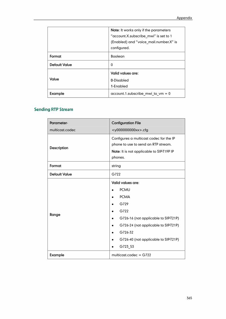
Appendix
365
Note: It works only if the parameters
“account.X.subscribe_mwi” is set to 1
(Enabled) and “voice_mail.number.X” is
configured.
Format Boolean
Default Value 0
Value
Valid values are:
0-Disabled
1-Enabled
Example account.1.subscribe_mwi_to_vm = 0
Parameter-
multicast.codec
Configuration File
<y0000000000xx>.cfg
Description
Configures a multicast codec for the IP
phone to use to send an RTP stream.
Note: It is not applicable to SIP-T19P IP
phones.
Format string
Default Value G722
Range
Valid values are:
PCMU
PCMA
G729
G722
G726-16 (not applicable to SIP-T21P)
G726-24 (not applicable to SIP-T21P)
G726-32
G726-40 (not applicable to SIP-T21P)
G723_53
Example multicast.codec = G722
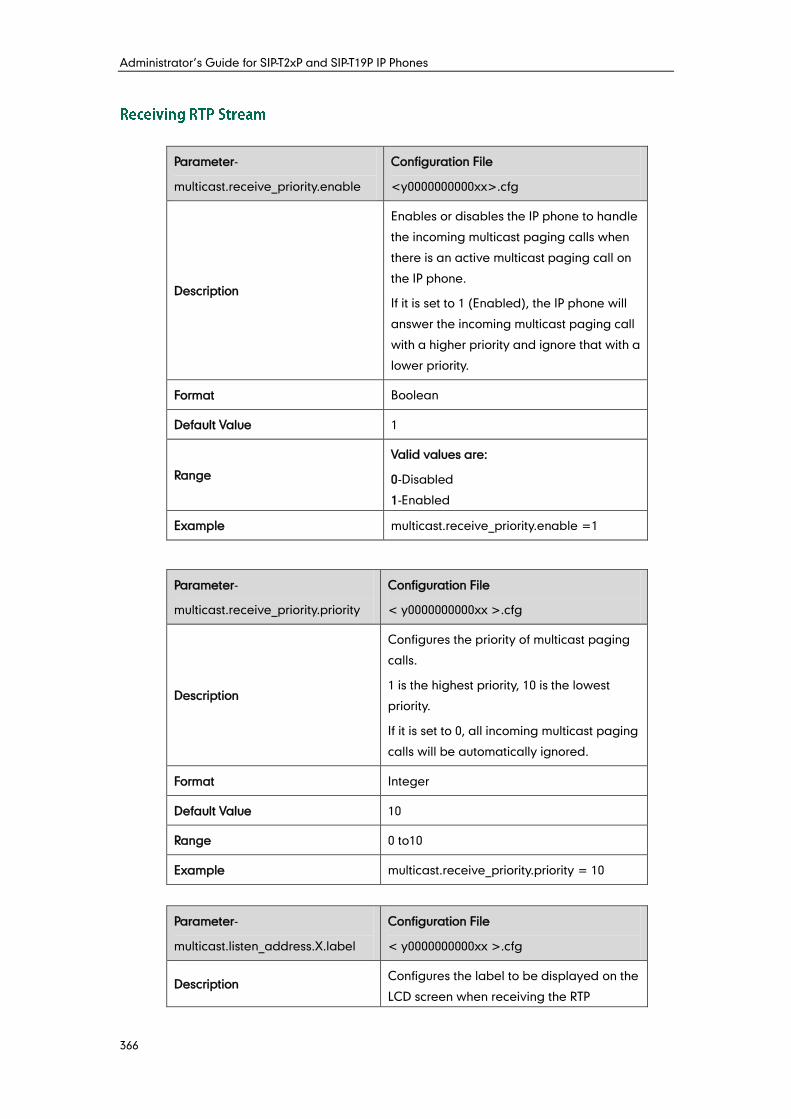
Administrator’s Guide for SIP-T2xP and SIP-T19P IP Phones
366
Parameter-
multicast.receive_priority.enable
Configuration File
<y0000000000xx>.cfg
Description
Enables or disables the IP phone to handle
the incoming multicast paging calls when
there is an active multicast paging call on
the IP phone.
If it is set to 1 (Enabled), the IP phone will
answer the incoming multicast paging call
with a higher priority and ignore that with a
lower priority.
Format Boolean
Default Value 1
Range
Valid values are:
0-Disabled
1-Enabled
Example multicast.receive_priority.enable =1
Parameter-
multicast.receive_priority.priority
Configuration File
< y0000000000xx >.cfg
Description
Configures the priority of multicast paging
calls.
1 is the highest priority, 10 is the lowest
priority.
If it is set to 0, all incoming multicast paging
calls will be automatically ignored.
Format Integer
Default Value 10
Range 0 to10
Example multicast.receive_priority.priority = 10
Parameter-
multicast.listen_address.X.label
Configuration File
< y0000000000xx >.cfg
Description Configures the label to be displayed on the
LCD screen when receiving the RTP
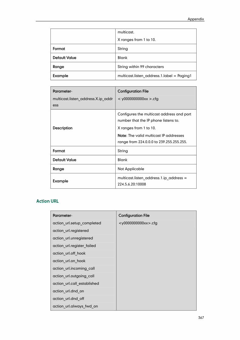
Appendix
367
multicast.
X ranges from 1 to 10.
Format String
Default Value Blank
Range String within 99 characters
Example multicast.listen_address.1.label = Paging1
Parameter-
multicast.listen_address.X.ip_addr
ess
Configuration File
< y0000000000xx >.cfg
Description
Configures the multicast address and port
number that the IP phone listens to.
X ranges from 1 to 10.
Note: The valid multicast IP addresses
range from 224.0.0.0 to 239.255.255.255.
Format String
Default Value Blank
Range Not Applicable
Example multicast.listen_address.1.ip_address =
224.5.6.20:10008
Parameter-
action_url.setup_completed
action_url.registered
action_url.unregistered
action_url.register_failed
action_url.off_hook
action_url.on_hook
action_url.incoming_call
action_url.outgoing_call
action_url.call_established
action_url.dnd_on
action_url.dnd_off
action_url.always_fwd_on
Configuration File
<y0000000000xx>.cfg
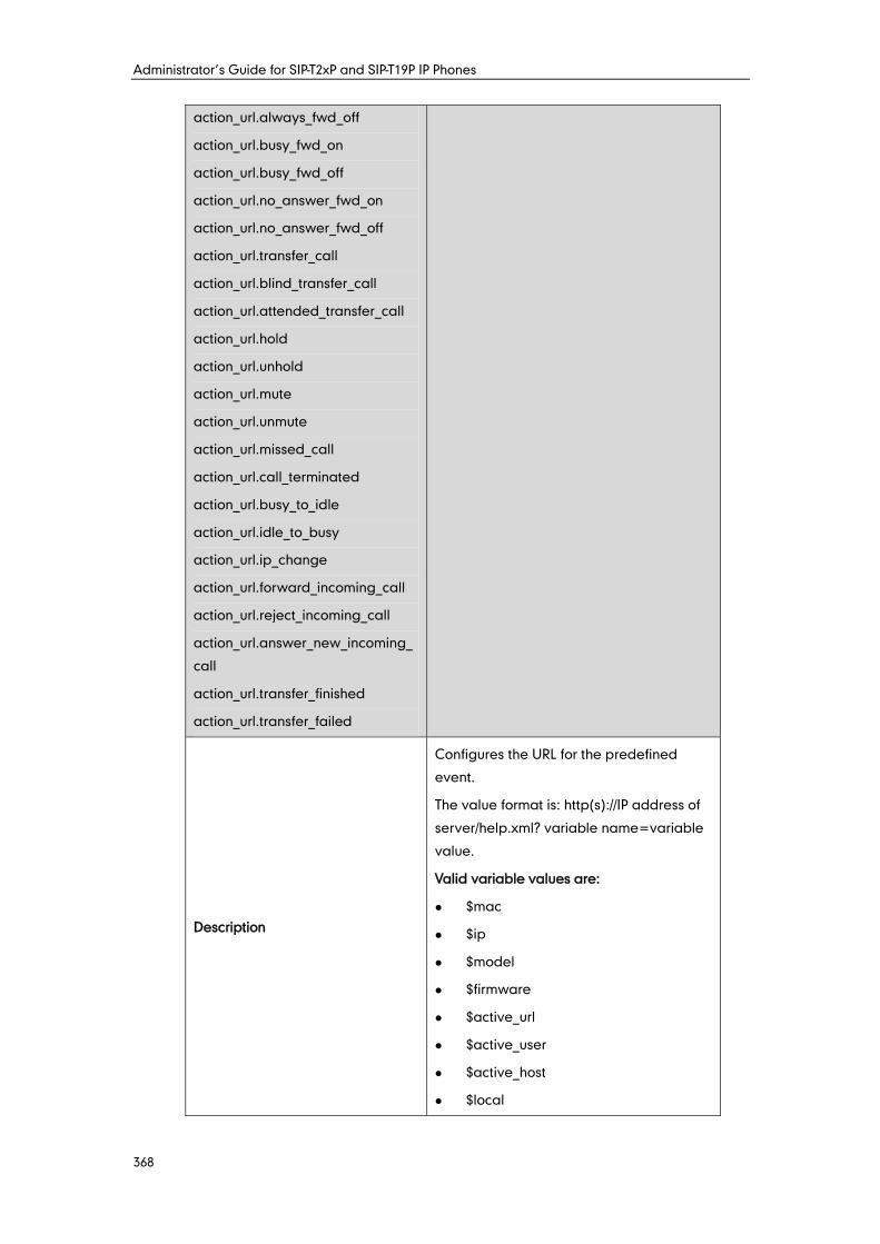
Administrator’s Guide for SIP-T2xP and SIP-T19P IP Phones
368
action_url.always_fwd_off
action_url.busy_fwd_on
action_url.busy_fwd_off
action_url.no_answer_fwd_on
action_url.no_answer_fwd_off
action_url.transfer_call
action_url.blind_transfer_call
action_url.attended_transfer_call
action_url.hold
action_url.unhold
action_url.mute
action_url.unmute
action_url.missed_call
action_url.call_terminated
action_url.busy_to_idle
action_url.idle_to_busy
action_url.ip_change
action_url.forward_incoming_call
action_url.reject_incoming_call
action_url.answer_new_incoming_
call
action_url.transfer_finished
action_url.transfer_failed
Description
Configures the URL for the predefined
event.
The value format is: http(s)://IP address of
server/help.xml? variable name=variable
value.
Valid variable values are:
$mac
$ip
$model
$firmware
$active_url
$active_user
$active_host
$local
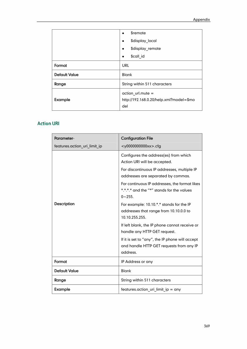
Appendix
369
$remote
$display_local
$display_remote
$call_id
Format URL
Default Value Blank
Range String within 511 characters
Example
action_url.mute =
http://192.168.0.20/help.xml?model=$mo
del
Parameter-
features.action_uri_limit_ip
Configuration File
<y0000000000xx>.cfg
Description
Configures the address(es) from which
Action URI will be accepted.
For discontinuous IP addresses, multiple IP
addresses are separated by commas.
For continuous IP addresses, the format likes
*.*.*.* and the “*” stands for the values
0~255.
For example: 10.10.*.* stands for the IP
addresses that range from 10.10.0.0 to
10.10.255.255.
If left blank, the IP phone cannot receive or
handle any HTTP GET request.
If it is set to “any”, the IP phone will accept
and handle HTTP GET requests from any IP
address.
Format IP Address or any
Default Value Blank
Range String within 511 characters
Example features.action_uri_limit_ip = any
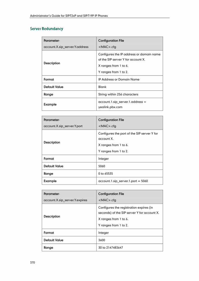
Administrator’s Guide for SIP-T2xP and SIP-T19P IP Phones
370
Parameter-
account.X.sip_server.Y.address
Configuration File
<MAC>.cfg
Description
Configures the IP address or domain name
of the SIP server Y for account X.
X ranges from 1 to 6.
Y ranges from 1 to 2.
Format IP Address or Domain Name
Default Value Blank
Range String within 256 characters
Example account.1.sip_server.1.address =
yealink.pbx.com
Parameter-
account.X.sip_server.Y.port
Configuration File
<MAC>.cfg
Description
Configures the port of the SIP server Y for
account X.
X ranges from 1 to 6.
Y ranges from 1 to 2.
Format Integer
Default Value 5060
Range 0 to 65535
Example account.1.sip_server.1.port = 5060
Parameter-
account.X.sip_server.Y.expires
Configuration File
<MAC>.cfg
Description
Configures the registration expires (in
seconds) of the SIP server Y for account X.
X ranges from 1 to 6.
Y ranges from 1 to 2.
Format Integer
Default Value 3600
Range 30 to 2147483647
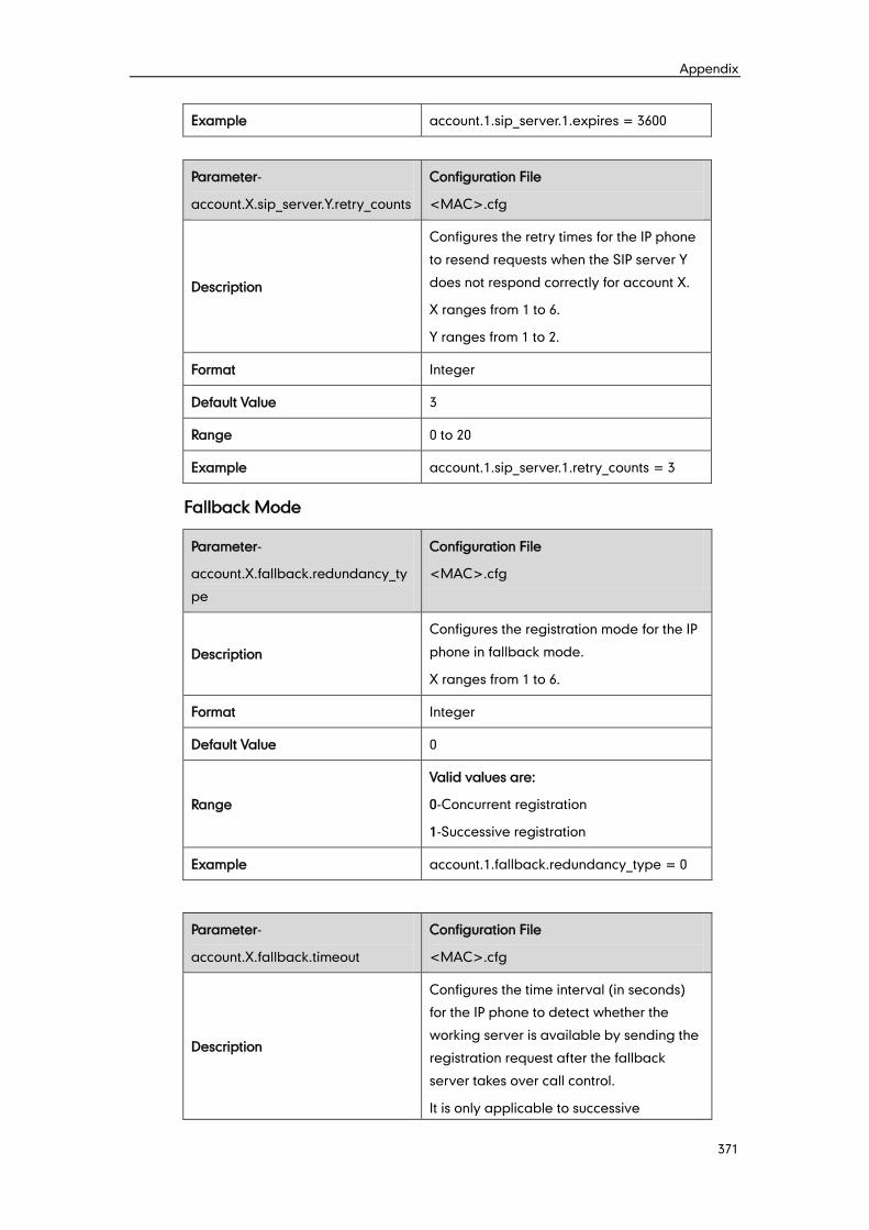
Appendix
371
Example account.1.sip_server.1.expires = 3600
Parameter-
account.X.sip_server.Y.retry_counts
Configuration File
<MAC>.cfg
Description
Configures the retry times for the IP phone
to resend requests when the SIP server Y
does not respond correctly for account X.
X ranges from 1 to 6.
Y ranges from 1 to 2.
Format Integer
Default Value 3
Range 0 to 20
Example account.1.sip_server.1.retry_counts = 3
Fallback Mode
Parameter-
account.X.fallback.redundancy_ty
pe
Configuration File
<MAC>.cfg
Description
Configures the registration mode for the IP
phone in fallback mode.
X ranges from 1 to 6.
Format Integer
Default Value 0
Range
Valid values are:
0-Concurrent registration
1-Successive registration
Example account.1.fallback.redundancy_type = 0
Parameter-
account.X.fallback.timeout
Configuration File
<MAC>.cfg
Description
Configures the time interval (in seconds)
for the IP phone to detect whether the
working server is available by sending the
registration request after the fallback
server takes over call control.
It is only applicable to successive
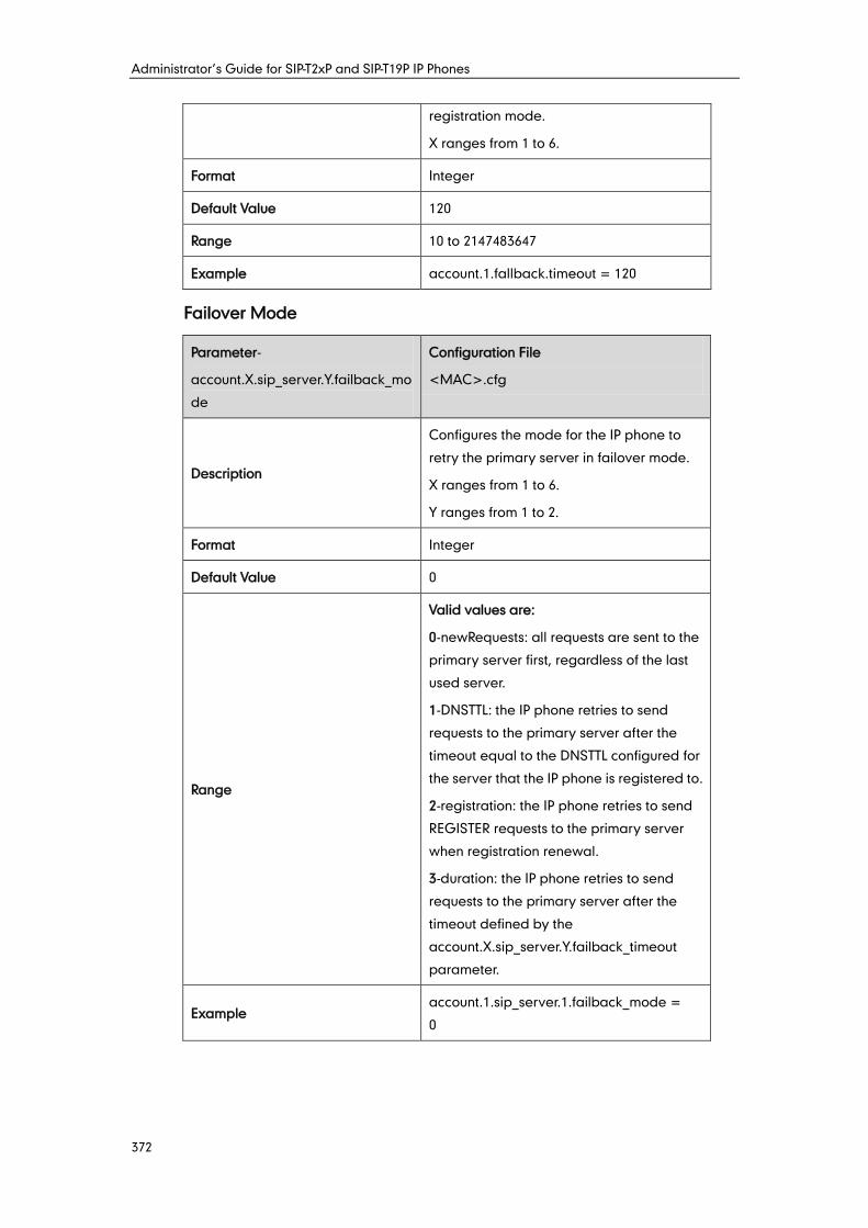
Administrator’s Guide for SIP-T2xP and SIP-T19P IP Phones
372
registration mode.
X ranges from 1 to 6.
Format Integer
Default Value 120
Range 10 to 2147483647
Example account.1.fallback.timeout = 120
Failover Mode
Parameter-
account.X.sip_server.Y.failback_mo
de
Configuration File
<MAC>.cfg
Description
Configures the mode for the IP phone to
retry the primary server in failover mode.
X ranges from 1 to 6.
Y ranges from 1 to 2.
Format Integer
Default Value 0
Range
Valid values are:
0-newRequests: all requests are sent to the
primary server first, regardless of the last
used server.
1-DNSTTL: the IP phone retries to send
requests to the primary server after the
timeout equal to the DNSTTL configured for
the server that the IP phone is registered to.
2-registration: the IP phone retries to send
REGISTER requests to the primary server
when registration renewal.
3-duration: the IP phone retries to send
requests to the primary server after the
timeout defined by the
account.X.sip_server.Y.failback_timeout
parameter.
Example account.1.sip_server.1.failback_mode =
0
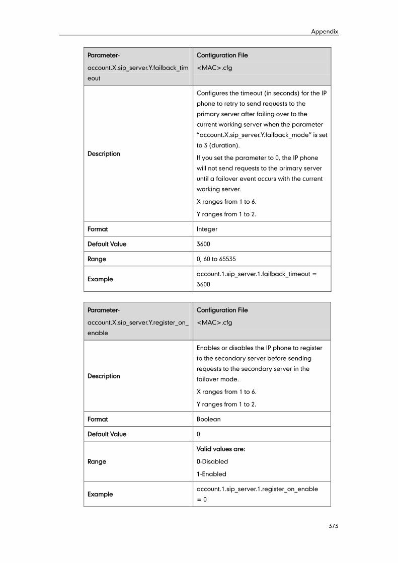
Appendix
373
Parameter-
account.X.sip_server.Y.failback_tim
eout
Configuration File
<MAC>.cfg
Description
Configures the timeout (in seconds) for the IP
phone to retry to send requests to the
primary server after failing over to the
current working server when the parameter
“account.X.sip_server.Y.failback_mode” is set
to 3 (duration).
If you set the parameter to 0, the IP phone
will not send requests to the primary server
until a failover event occurs with the current
working server.
X ranges from 1 to 6.
Y ranges from 1 to 2.
Format Integer
Default Value 3600
Range 0, 60 to 65535
Example account.1.sip_server.1.failback_timeout =
3600
Parameter-
account.X.sip_server.Y.register_on_
enable
Configuration File
<MAC>.cfg
Description
Enables or disables the IP phone to register
to the secondary server before sending
requests to the secondary server in the
failover mode.
X ranges from 1 to 6.
Y ranges from 1 to 2.
Format Boolean
Default Value 0
Range
Valid values are:
0-Disabled
1-Enabled
Example account.1.sip_server.1.register_on_enable
= 0
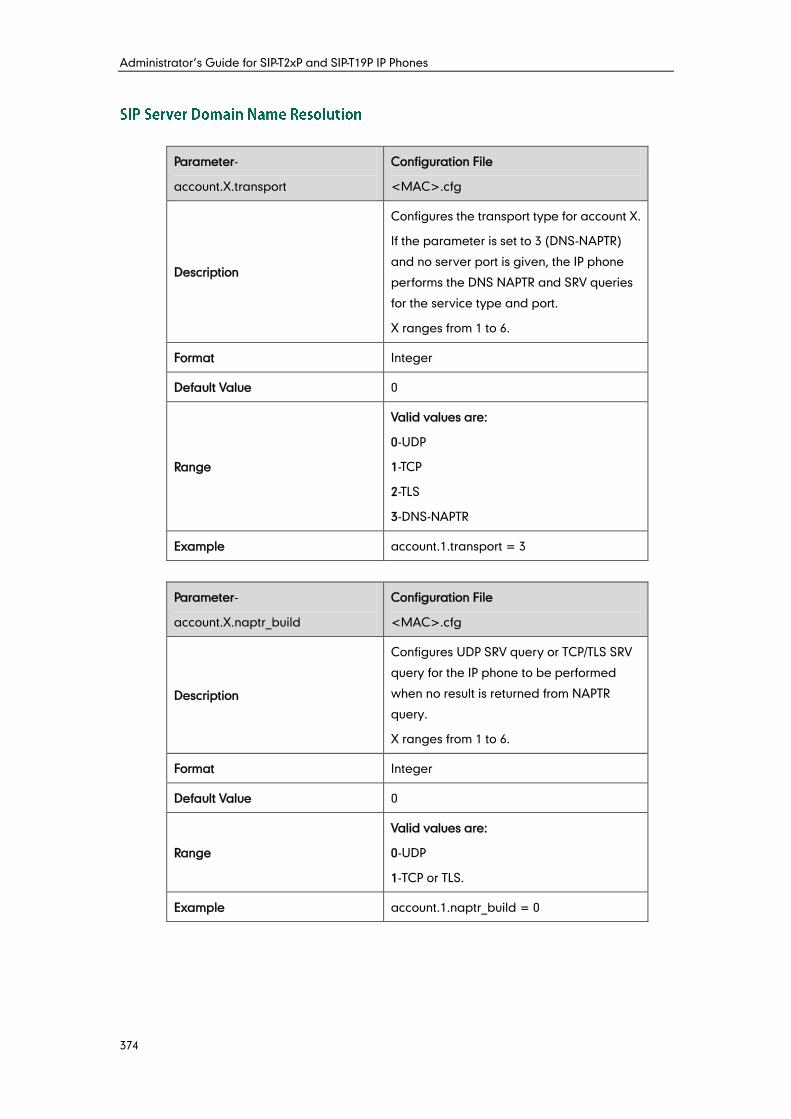
Administrator’s Guide for SIP-T2xP and SIP-T19P IP Phones
374
Parameter-
account.X.transport
Configuration File
<MAC>.cfg
Description
Configures the transport type for account X.
If the parameter is set to 3 (DNS-NAPTR)
and no server port is given, the IP phone
performs the DNS NAPTR and SRV queries
for the service type and port.
X ranges from 1 to 6.
Format Integer
Default Value 0
Range
Valid values are:
0-UDP
1-TCP
2-TLS
3-DNS-NAPTR
Example account.1.transport = 3
Parameter-
account.X.naptr_build
Configuration File
<MAC>.cfg
Description
Configures UDP SRV query or TCP/TLS SRV
query for the IP phone to be performed
when no result is returned from NAPTR
query.
X ranges from 1 to 6.
Format Integer
Default Value 0
Range
Valid values are:
0-UDP
1-TCP or TLS.
Example account.1.naptr_build = 0
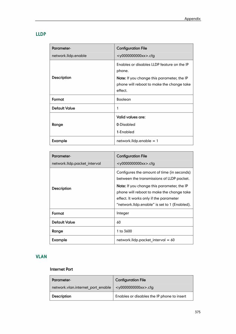
Appendix
375
Parameter-
network.lldp.enable
Configuration File
<y0000000000xx>.cfg
Description
Enables or disables LLDP feature on the IP
phone.
Note: If you change this parameter, the IP
phone will reboot to make the change take
effect.
Format Boolean
Default Value 1
Range
Valid values are:
0-Disabled
1-Enabled
Example network.lldp.enable = 1
Parameter-
network.lldp.packet_interval
Configuration File
<y0000000000xx>.cfg
Description
Configures the amount of time (in seconds)
between the transmissions of LLDP packet.
Note: If you change this parameter, the IP
phone will reboot to make the change take
effect. It works only if the parameter
“network.lldp.enable” is set to 1 (Enabled).
Format Integer
Default Value 60
Range 1 to 3600
Example network.lldp.packet_interval = 60
Internet Port
Parameter-
network.vlan.internet_port_enable
Configuration File
<y0000000000xx>.cfg
Description Enables or disables the IP phone to insert
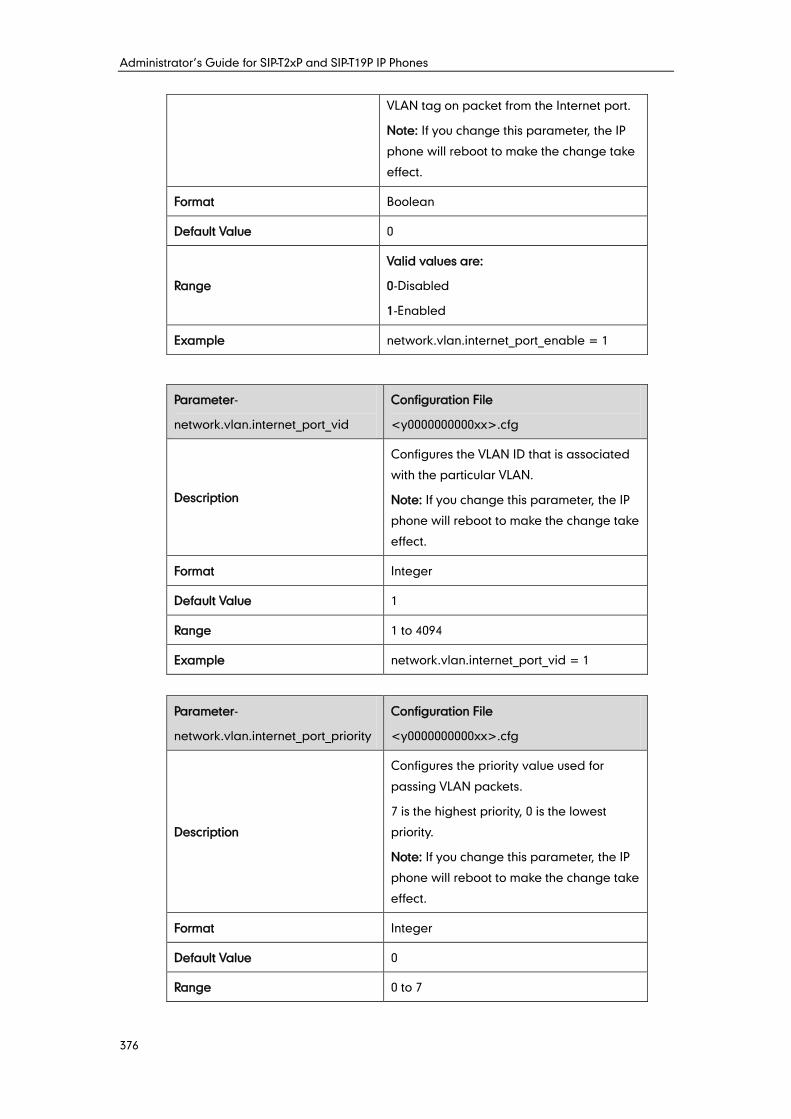
Administrator’s Guide for SIP-T2xP and SIP-T19P IP Phones
376
VLAN tag on packet from the Internet port.
Note: If you change this parameter, the IP
phone will reboot to make the change take
effect.
Format Boolean
Default Value 0
Range
Valid values are:
0-Disabled
1-Enabled
Example network.vlan.internet_port_enable = 1
Parameter-
network.vlan.internet_port_vid
Configuration File
<y0000000000xx>.cfg
Description
Configures the VLAN ID that is associated
with the particular VLAN.
Note: If you change this parameter, the IP
phone will reboot to make the change take
effect.
Format Integer
Default Value 1
Range 1 to 4094
Example network.vlan.internet_port_vid = 1
Parameter-
network.vlan.internet_port_priority
Configuration File
<y0000000000xx>.cfg
Description
Configures the priority value used for
passing VLAN packets.
7 is the highest priority, 0 is the lowest
priority.
Note: If you change this parameter, the IP
phone will reboot to make the change take
effect.
Format Integer
Default Value 0
Range 0 to 7
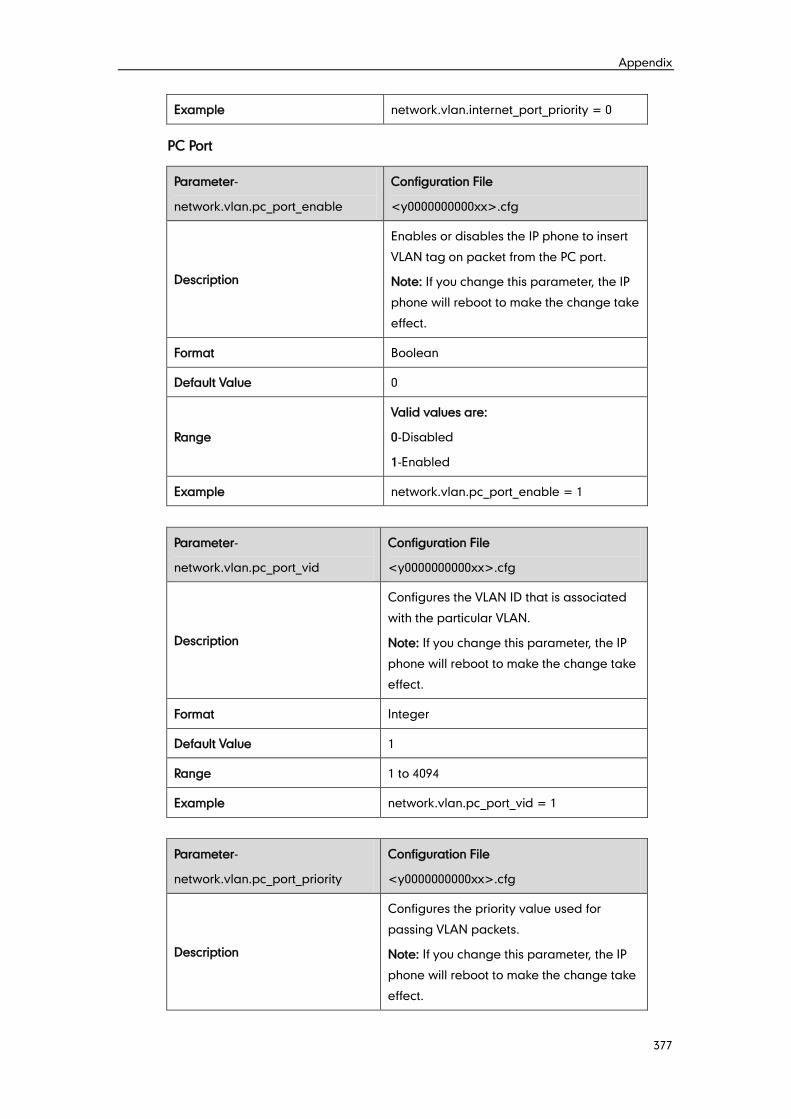
Appendix
377
Example network.vlan.internet_port_priority = 0
PC Port
Parameter-
network.vlan.pc_port_enable
Configuration File
<y0000000000xx>.cfg
Description
Enables or disables the IP phone to insert
VLAN tag on packet from the PC port.
Note: If you change this parameter, the IP
phone will reboot to make the change take
effect.
Format Boolean
Default Value 0
Range
Valid values are:
0-Disabled
1-Enabled
Example network.vlan.pc_port_enable = 1
Parameter-
network.vlan.pc_port_vid
Configuration File
<y0000000000xx>.cfg
Description
Configures the VLAN ID that is associated
with the particular VLAN.
Note: If you change this parameter, the IP
phone will reboot to make the change take
effect.
Format Integer
Default Value 1
Range 1 to 4094
Example network.vlan.pc_port_vid = 1
Parameter-
network.vlan.pc_port_priority
Configuration File
<y0000000000xx>.cfg
Description
Configures the priority value used for
passing VLAN packets.
Note: If you change this parameter, the IP
phone will reboot to make the change take
effect.
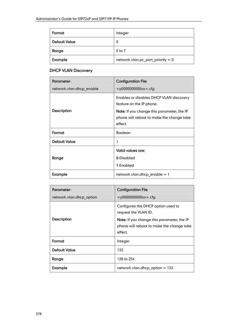
Administrator’s Guide for SIP-T2xP and SIP-T19P IP Phones
378
Format Integer
Default Value 0
Range 0 to 7
Example network.vlan.pc_port_priority = 0
DHCP VLAN Discovery
Parameter-
network.vlan.dhcp_enable
Configuration File
<y0000000000xx>.cfg
Description
Enables or disables DHCP VLAN discovery
feature on the IP phone.
Note: If you change this parameter, the IP
phone will reboot to make the change take
effect.
Format Boolean
Default Value 1
Range
Valid values are:
0-Disabled
1-Enabled
Example network.vlan.dhcp_enable = 1
Parameter-
network.vlan.dhcp_option
Configuration File
<y0000000000xx>.cfg
Description
Configures the DHCP option used to
request the VLAN ID.
Note: If you change this parameter, the IP
phone will reboot to make the change take
effect.
Format Integer
Default Value 132
Range 128 to 254
Example network.vlan.dhcp_option = 132
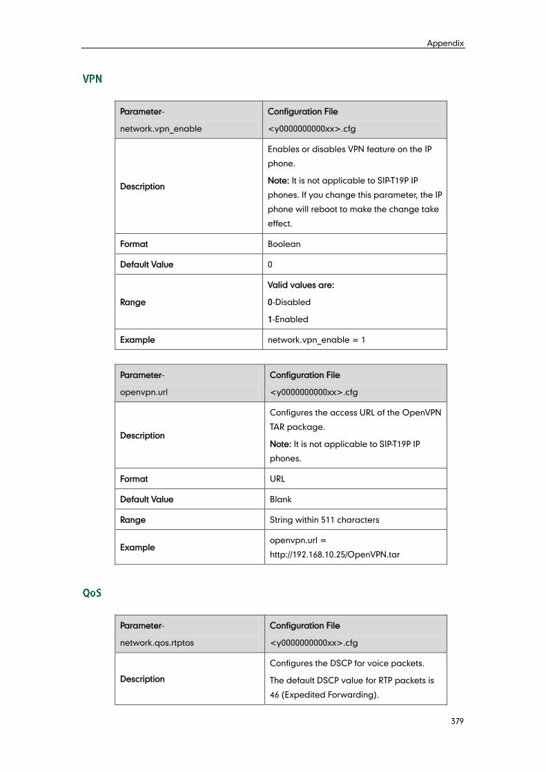
Appendix
379
Parameter-
network.vpn_enable
Configuration File
<y0000000000xx>.cfg
Description
Enables or disables VPN feature on the IP
phone.
Note: It is not applicable to SIP-T19P IP
phones. If you change this parameter, the IP
phone will reboot to make the change take
effect.
Format Boolean
Default Value 0
Range
Valid values are:
0-Disabled
1-Enabled
Example network.vpn_enable = 1
Parameter-
openvpn.url
Configuration File
<y0000000000xx>.cfg
Description
Configures the access URL of the OpenVPN
TAR package.
Note: It is not applicable to SIP-T19P IP
phones.
Format URL
Default Value Blank
Range String within 511 characters
Example openvpn.url =
http://192.168.10.25/OpenVPN.tar
Parameter-
network.qos.rtptos
Configuration File
<y0000000000xx>.cfg
Description
Configures the DSCP for voice packets.
The default DSCP value for RTP packets is
46 (Expedited Forwarding).
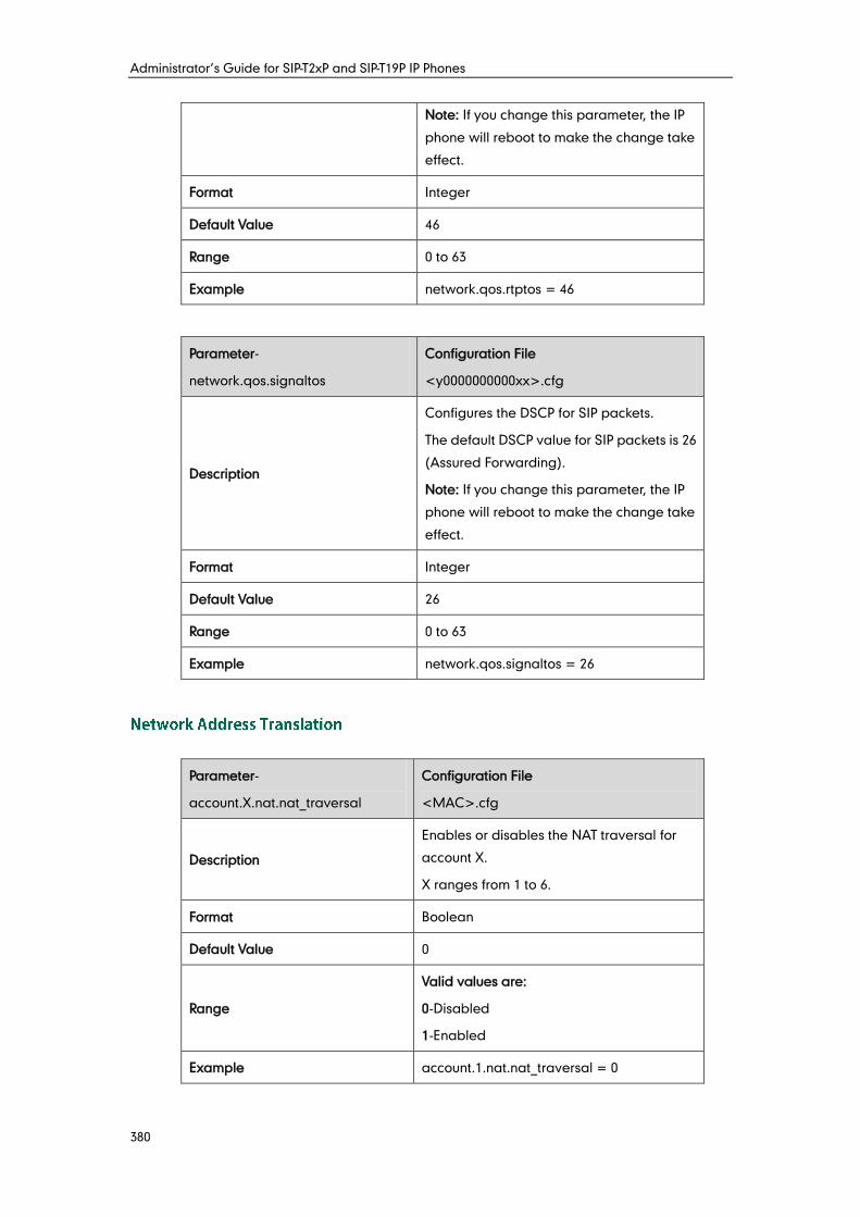
Administrator’s Guide for SIP-T2xP and SIP-T19P IP Phones
380
Note: If you change this parameter, the IP
phone will reboot to make the change take
effect.
Format Integer
Default Value 46
Range 0 to 63
Example network.qos.rtptos = 46
Parameter-
network.qos.signaltos
Configuration File
<y0000000000xx>.cfg
Description
Configures the DSCP for SIP packets.
The default DSCP value for SIP packets is 26
(Assured Forwarding).
Note: If you change this parameter, the IP
phone will reboot to make the change take
effect.
Format Integer
Default Value 26
Range 0 to 63
Example network.qos.signaltos = 26
Parameter-
account.X.nat.nat_traversal
Configuration File
<MAC>.cfg
Description
Enables or disables the NAT traversal for
account X.
X ranges from 1 to 6.
Format Boolean
Default Value 0
Range
Valid values are:
0-Disabled
1-Enabled
Example account.1.nat.nat_traversal = 0
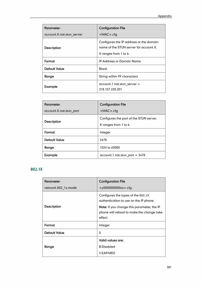
Appendix
381
Parameter-
account.X.nat.stun_server
Configuration File
<MAC>.cfg
Description
Configures the IP address or the domain
name of the STUN server for account X.
X ranges from 1 to 6.
Format IP Address or Domain Name
Default Value Blank
Range String within 99 characters
Example account.1.nat.stun_server =
218.107.220.201
Parameter-
account.X.nat.stun_port
Configuration File
<MAC>.cfg
Description Configures the port of the STUN server.
X ranges from 1 to 6.
Format Integer
Default Value 3478
Range 1024 to 65000
Example account.1.nat.stun_port = 3478
Parameter-
network.802_1x.mode
Configuration File
<y0000000000xx>.cfg
Description
Configures the types of the 802.1X
authentication to use on the IP phone.
Note: If you change this parameter, the IP
phone will reboot to make the change take
effect.
Format Integer
Default Value 0
Range
Valid values are:
0-Disabled
1-EAP-MD5
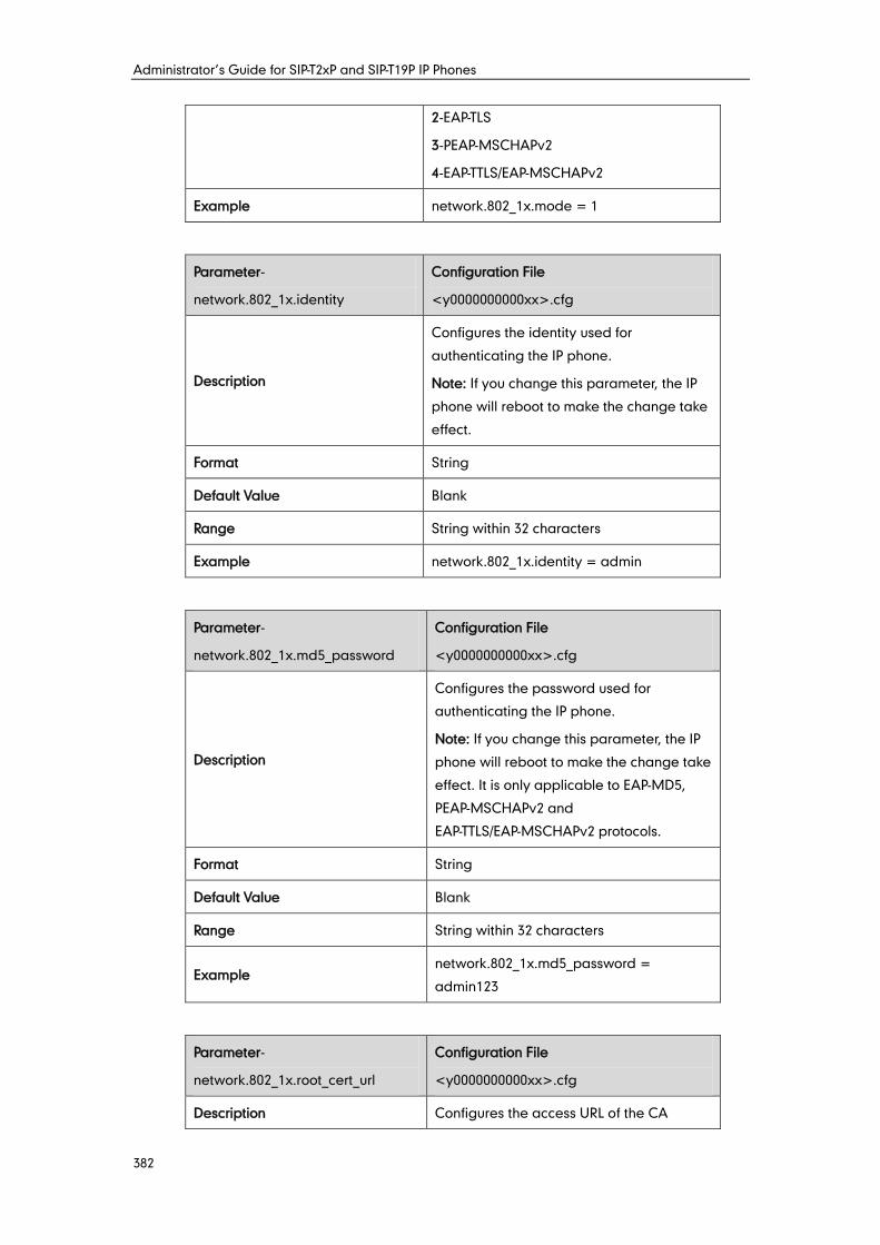
Administrator’s Guide for SIP-T2xP and SIP-T19P IP Phones
382
2-EAP-TLS
3-PEAP-MSCHAPv2
4-EAP-TTLS/EAP-MSCHAPv2
Example network.802_1x.mode = 1
Parameter-
network.802_1x.identity
Configuration File
<y0000000000xx>.cfg
Description
Configures the identity used for
authenticating the IP phone.
Note: If you change this parameter, the IP
phone will reboot to make the change take
effect.
Format String
Default Value Blank
Range String within 32 characters
Example network.802_1x.identity = admin
Parameter-
network.802_1x.md5_password
Configuration File
<y0000000000xx>.cfg
Description
Configures the password used for
authenticating the IP phone.
Note: If you change this parameter, the IP
phone will reboot to make the change take
effect. It is only applicable to EAP-MD5,
PEAP-MSCHAPv2 and
EAP-TTLS/EAP-MSCHAPv2 protocols.
Format String
Default Value Blank
Range String within 32 characters
Example network.802_1x.md5_password =
admin123
Parameter-
network.802_1x.root_cert_url
Configuration File
<y0000000000xx>.cfg
Description Configures the access URL of the CA

Appendix
383
certificate used for authentication.
Note: If you change this parameter, the IP
phone will reboot to make the change take
effect. It is only applicable to EAP-TLS,
PEAP-MSCHAPv2 and
EAP-TTLS/EAP-MSCHAPv2 protocols. The
format of the certificate must be *.pem,
*.crt, *.cer or *.der.
Format URL
Default Value Blank
Range String within 511 characters
Example network.802_1x.root_cert_url =
http://192.168.1.10/ca.pem
Parameter-
network.802_1x.client_cert_url
Configuration File
<y0000000000xx>.cfg
Description
Configures the access URL of the device
certificate used for authentication.
Note: If you change this parameter, the IP
phone will reboot to make the change take
effect. It is only applicable to the EAP-TLS
protocol. The format of the certificate must
be *.pem or *.cer.
Format URL
Default Value Blank
Range String within 511 characters
Example network.802_1x.client_cert_url =
http://192.168.1.10/ client.pem
Parameter-
managementserver.enable
Configuration File
<y0000000000xx>.cfg
Description Enables or disables TR-069 feature on the IP
phone.
Format Integer
Default Value 0
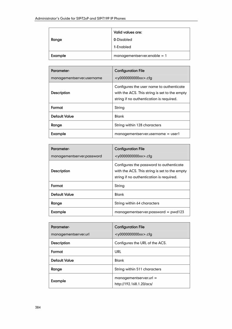
Administrator’s Guide for SIP-T2xP and SIP-T19P IP Phones
384
Range
Valid values are:
0-Disabled
1-Enabled
Example managementserver.enable = 1
Parameter-
managementserver.username
Configuration File
<y0000000000xx>.cfg
Description
Configures the user name to authenticate
with the ACS. This string is set to the empty
string if no authentication is required.
Format String
Default Value Blank
Range String within 128 characters
Example managementserver.username = user1
Parameter-
managementserver.password
Configuration File
<y0000000000xx>.cfg
Description
Configures the password to authenticate
with the ACS. This string is set to the empty
string if no authentication is required.
Format String
Default Value Blank
Range String within 64 characters
Example managementserver.password = pwd123
Parameter-
managementserver.url
Configuration File
<y0000000000xx>.cfg
Description Configures the URL of the ACS.
Format URL
Default Value Blank
Range String within 511 characters
Example managementserver.url =
http://192.168.1.20/acs/
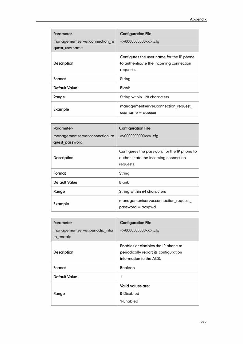
Appendix
385
Parameter-
managementserver.connection_re
quest_username
Configuration File
<y0000000000xx>.cfg
Description
Configures the user name for the IP phone
to authenticate the incoming connection
requests.
Format String
Default Value Blank
Range String within 128 characters
Example managementserver.connection_request_
username = acsuser
Parameter-
managementserver.connection_re
quest_password
Configuration File
<y0000000000xx>.cfg
Description
Configures the password for the IP phone to
authenticate the incoming connection
requests.
Format String
Default Value Blank
Range String within 64 characters
Example managementserver.connection_request_
password = acspwd
Parameter-
managementserver.periodic_infor
m_enable
Configuration File
<y0000000000xx>.cfg
Description
Enables or disables the IP phone to
periodically report its configuration
information to the ACS.
Format Boolean
Default Value 1
Range
Valid values are:
0-Disabled
1-Enabled
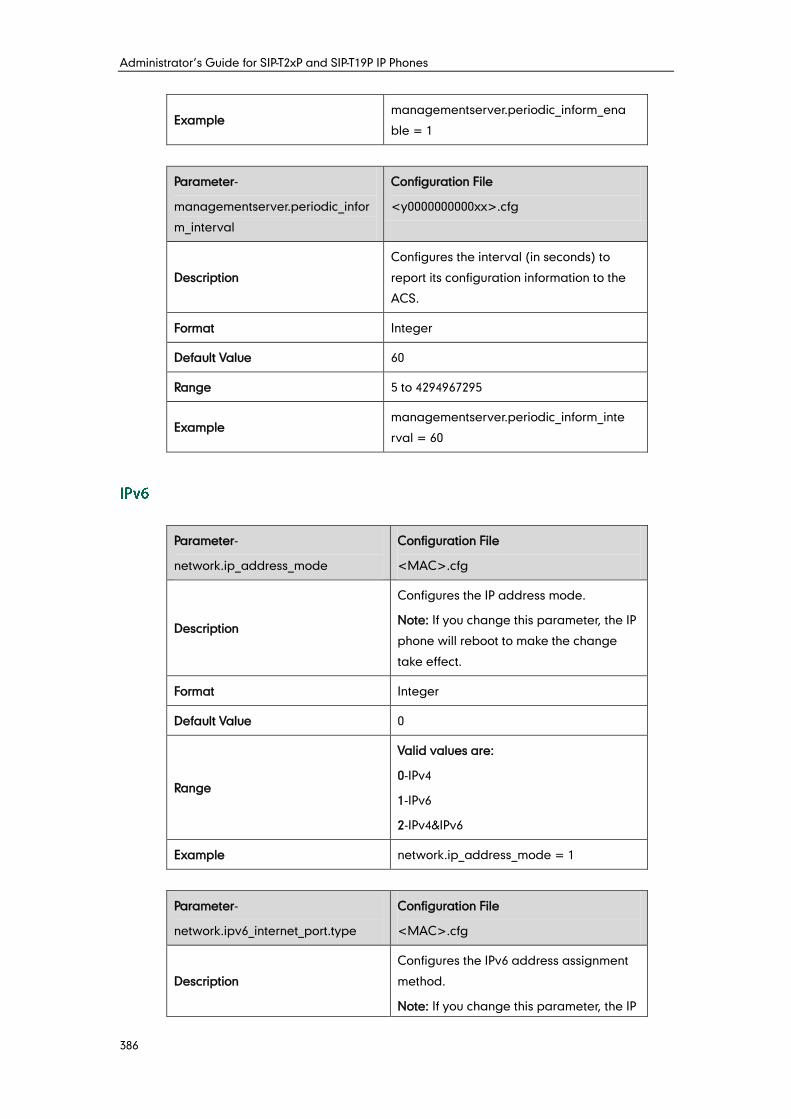
Administrator’s Guide for SIP-T2xP and SIP-T19P IP Phones
386
Example managementserver.periodic_inform_ena
ble = 1
Parameter-
managementserver.periodic_infor
m_interval
Configuration File
<y0000000000xx>.cfg
Description
Configures the interval (in seconds) to
report its configuration information to the
ACS.
Format Integer
Default Value 60
Range 5 to 4294967295
Example managementserver.periodic_inform_inte
rval = 60
Parameter-
network.ip_address_mode
Configuration File
<MAC>.cfg
Description
Configures the IP address mode.
Note: If you change this parameter, the IP
phone will reboot to make the change
take effect.
Format Integer
Default Value 0
Range
Valid values are:
0-IPv4
1-IPv6
2-IPv4&IPv6
Example network.ip_address_mode = 1
Parameter-
network.ipv6_internet_port.type
Configuration File
<MAC>.cfg
Description
Configures the IPv6 address assignment
method.
Note: If you change this parameter, the IP
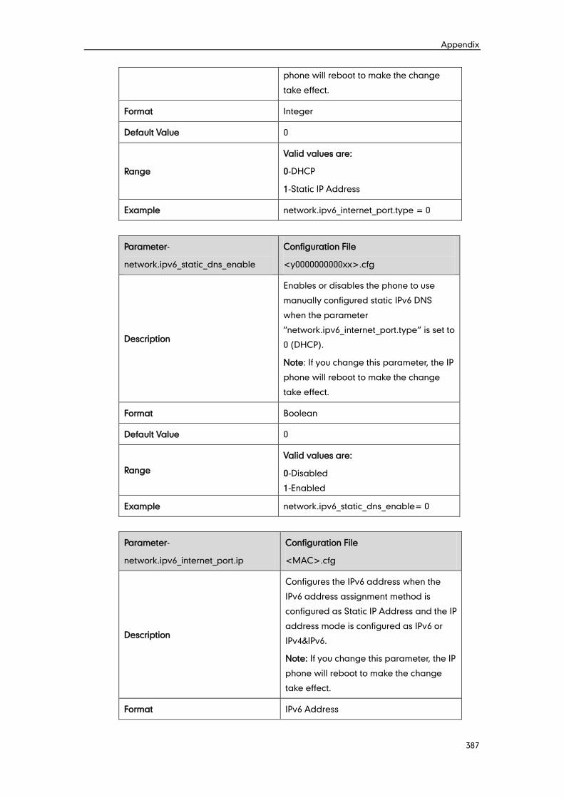
Appendix
387
phone will reboot to make the change
take effect.
Format Integer
Default Value 0
Range
Valid values are:
0-DHCP
1-Static IP Address
Example network.ipv6_internet_port.type = 0
Parameter-
network.ipv6_static_dns_enable
Configuration File
<y0000000000xx>.cfg
Description
Enables or disables the phone to use
manually configured static IPv6 DNS
when the parameter
“network.ipv6_internet_port.type” is set to
0 (DHCP).
Note: If you change this parameter, the IP
phone will reboot to make the change
take effect.
Format Boolean
Default Value 0
Range
Valid values are:
0-Disabled
1-Enabled
Example network.ipv6_static_dns_enable= 0
Parameter-
network.ipv6_internet_port.ip
Configuration File
<MAC>.cfg
Description
Configures the IPv6 address when the
IPv6 address assignment method is
configured as Static IP Address and the IP
address mode is configured as IPv6 or
IPv4&IPv6.
Note: If you change this parameter, the IP
phone will reboot to make the change
take effect.
Format IPv6 Address
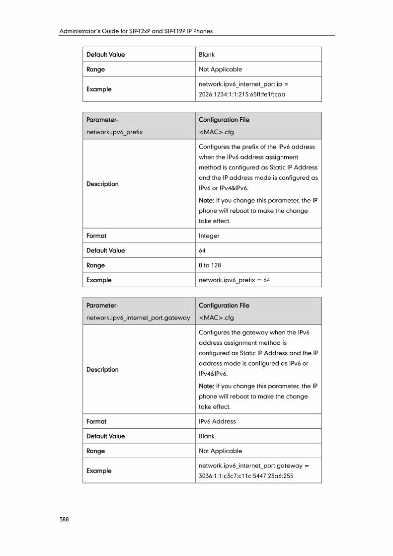
Administrator’s Guide for SIP-T2xP and SIP-T19P IP Phones
388
Default Value Blank
Range Not Applicable
Example network.ipv6_internet_port.ip =
2026:1234:1:1:215:65ff:fe1f:caa
Parameter-
network.ipv6_prefix
Configuration File
<MAC>.cfg
Description
Configures the prefix of the IPv6 address
when the IPv6 address assignment
method is configured as Static IP Address
and the IP address mode is configured as
IPv6 or IPv4&IPv6.
Note: If you change this parameter, the IP
phone will reboot to make the change
take effect.
Format Integer
Default Value 64
Range 0 to 128
Example network.ipv6_prefix = 64
Parameter-
network.ipv6_internet_port.gateway
Configuration File
<MAC>.cfg
Description
Configures the gateway when the IPv6
address assignment method is
configured as Static IP Address and the IP
address mode is configured as IPv6 or
IPv4&IPv6.
Note: If you change this parameter, the IP
phone will reboot to make the change
take effect.
Format IPv6 Address
Default Value Blank
Range Not Applicable
Example network.ipv6_internet_port.gateway =
3036:1:1:c3c7:c11c:5447:23a6:255
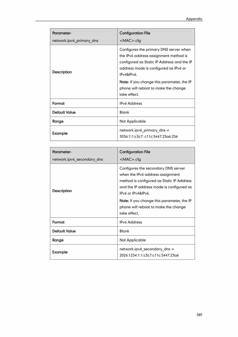
Appendix
389
Parameter-
network.ipv6_primary_dns
Configuration File
<MAC>.cfg
Description
Configures the primary DNS server when
the IPv6 address assignment method is
configured as Static IP Address and the IP
address mode is configured as IPv6 or
IPv4&IPv6.
Note: If you change this parameter, the IP
phone will reboot to make the change
take effect.
Format IPv6 Address
Default Value Blank
Range Not Applicable
Example network.ipv6_primary_dns =
3036:1:1:c3c7: c11c:5447:23a6:256
Parameter-
network.ipv6_secondary_dns
Configuration File
<MAC>.cfg
Description
Configures the secondary DNS server
when the IPv6 address assignment
method is configured as Static IP Address
and the IP address mode is configured as
IPv6 or IPv4&IPv6.
Note: If you change this parameter, the IP
phone will reboot to make the change
take effect.
Format IPv6 Address
Default Value Blank
Range Not Applicable
Example network.ipv6_secondary_dns =
2026:1234:1:1:c3c7:c11c:5447:23a6
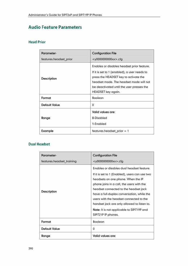
Administrator’s Guide for SIP-T2xP and SIP-T19P IP Phones
390
Parameter-
features.headset_prior
Configuration File
<y0000000000xx>.cfg
Description
Enables or disables headset prior feature.
If it is set to 1 (enabled), a user needs to
press the HEADSET key to activate the
headset mode. The headset mode will not
be deactivated until the user presses the
HEADSET key again.
Format Boolean
Default Value 0
Range
Valid values are:
0-Disabled
1-Enabled
Example features.headset_prior = 1
Parameter-
features.headset_training
Configuration File
<y0000000000xx>.cfg
Description
Enables or disables dual headset feature.
If it is set to 1 (Enabled), users can use two
headsets on one phone. When the IP
phone joins in a call, the users with the
headset connected to the headset jack
have a full-duplex conversation, while the
users with the headset connected to the
handset jack are only allowed to listen to.
Note: It is not applicable to SIP-T19P and
SIP-T21P IP phones.
Format Boolean
Default Value 0
Range Valid values are:
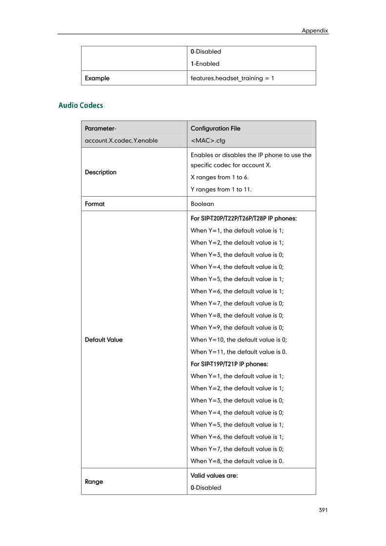
Appendix
391
0-Disabled
1-Enabled
Example features.headset_training = 1
Parameter-
account.X.codec.Y.enable
Configuration File
<MAC>.cfg
Description
Enables or disables the IP phone to use the
specific codec for account X.
X ranges from 1 to 6.
Y ranges from 1 to 11.
Format Boolean
Default Value
For SIP-T20P/T22P/T26P/T28P IP phones:
When Y=1, the default value is 1;
When Y=2, the default value is 1;
When Y=3, the default value is 0;
When Y=4, the default value is 0;
When Y=5, the default value is 1;
When Y=6, the default value is 1;
When Y=7, the default value is 0;
When Y=8, the default value is 0;
When Y=9, the default value is 0;
When Y=10, the default value is 0;
When Y=11, the default value is 0.
For SIP-T19P/T21P IP phones:
When Y=1, the default value is 1;
When Y=2, the default value is 1;
When Y=3, the default value is 0;
When Y=4, the default value is 0;
When Y=5, the default value is 1;
When Y=6, the default value is 1;
When Y=7, the default value is 0;
When Y=8, the default value is 0.
Range Valid values are:
0-Disabled
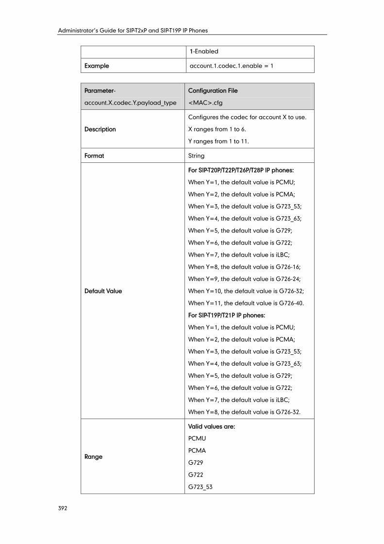
Administrator’s Guide for SIP-T2xP and SIP-T19P IP Phones
392
1-Enabled
Example account.1.codec.1.enable = 1
Parameter-
account.X.codec.Y.payload_type
Configuration File
<MAC>.cfg
Description
Configures the codec for account X to use.
X ranges from 1 to 6.
Y ranges from 1 to 11.
Format String
Default Value
For SIP-T20P/T22P/T26P/T28P IP phones:
When Y=1, the default value is PCMU;
When Y=2, the default value is PCMA;
When Y=3, the default value is G723_53;
When Y=4, the default value is G723_63;
When Y=5, the default value is G729;
When Y=6, the default value is G722;
When Y=7, the default value is iLBC;
When Y=8, the default value is G726-16;
When Y=9, the default value is G726-24;
When Y=10, the default value is G726-32;
When Y=11, the default value is G726-40.
For SIP-T19P/T21P IP phones:
When Y=1, the default value is PCMU;
When Y=2, the default value is PCMA;
When Y=3, the default value is G723_53;
When Y=4, the default value is G723_63;
When Y=5, the default value is G729;
When Y=6, the default value is G722;
When Y=7, the default value is iLBC;
When Y=8, the default value is G726-32.
Range
Valid values are:
PCMU
PCMA
G729
G722
G723_53
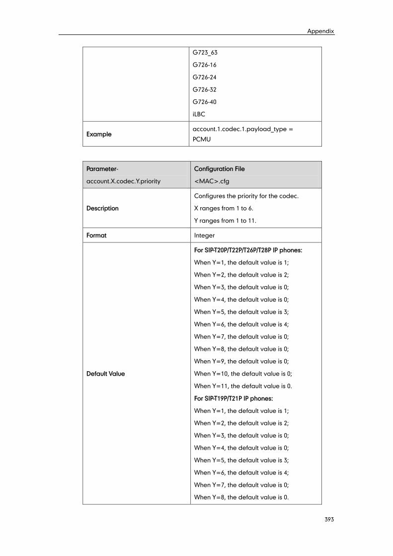
Appendix
393
G723_63
G726-16
G726-24
G726-32
G726-40
iLBC
Example account.1.codec.1.payload_type =
PCMU
Parameter-
account.X.codec.Y.priority
Configuration File
<MAC>.cfg
Description
Configures the priority for the codec.
X ranges from 1 to 6.
Y ranges from 1 to 11.
Format Integer
Default Value
For SIP-T20P/T22P/T26P/T28P IP phones:
When Y=1, the default value is 1;
When Y=2, the default value is 2;
When Y=3, the default value is 0;
When Y=4, the default value is 0;
When Y=5, the default value is 3;
When Y=6, the default value is 4;
When Y=7, the default value is 0;
When Y=8, the default value is 0;
When Y=9, the default value is 0;
When Y=10, the default value is 0;
When Y=11, the default value is 0.
For SIP-T19P/T21P IP phones:
When Y=1, the default value is 1;
When Y=2, the default value is 2;
When Y=3, the default value is 0;
When Y=4, the default value is 0;
When Y=5, the default value is 3;
When Y=6, the default value is 4;
When Y=7, the default value is 0;
When Y=8, the default value is 0.
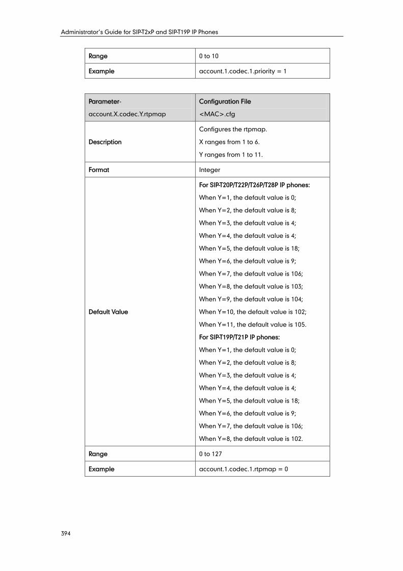
Administrator’s Guide for SIP-T2xP and SIP-T19P IP Phones
394
Range 0 to 10
Example account.1.codec.1.priority = 1
Parameter-
account.X.codec.Y.rtpmap
Configuration File
<MAC>.cfg
Description
Configures the rtpmap.
X ranges from 1 to 6.
Y ranges from 1 to 11.
Format Integer
Default Value
For SIP-T20P/T22P/T26P/T28P IP phones:
When Y=1, the default value is 0;
When Y=2, the default value is 8;
When Y=3, the default value is 4;
When Y=4, the default value is 4;
When Y=5, the default value is 18;
When Y=6, the default value is 9;
When Y=7, the default value is 106;
When Y=8, the default value is 103;
When Y=9, the default value is 104;
When Y=10, the default value is 102;
When Y=11, the default value is 105.
For SIP-T19P/T21P IP phones:
When Y=1, the default value is 0;
When Y=2, the default value is 8;
When Y=3, the default value is 4;
When Y=4, the default value is 4;
When Y=5, the default value is 18;
When Y=6, the default value is 9;
When Y=7, the default value is 106;
When Y=8, the default value is 102.
Range 0 to 127
Example account.1.codec.1.rtpmap = 0
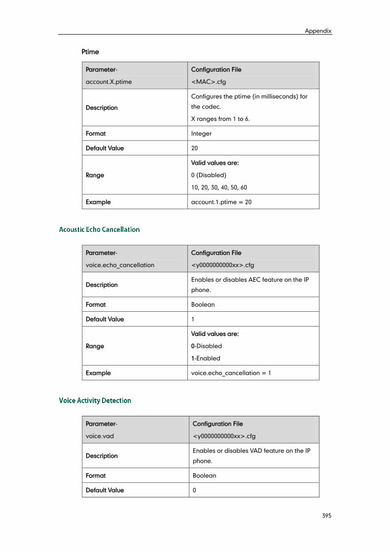
Appendix
395
Ptime
Parameter-
account.X.ptime
Configuration File
<MAC>.cfg
Description
Configures the ptime (in milliseconds) for
the codec.
X ranges from 1 to 6.
Format Integer
Default Value 20
Range
Valid values are:
0 (Disabled)
10, 20, 30, 40, 50, 60
Example account.1.ptime = 20
Parameter-
voice.echo_cancellation
Configuration File
<y0000000000xx>.cfg
Description Enables or disables AEC feature on the IP
phone.
Format Boolean
Default Value 1
Range
Valid values are:
0-Disabled
1-Enabled
Example voice.echo_cancellation = 1
Parameter-
voice.vad
Configuration File
<y0000000000xx>.cfg
Description Enables or disables VAD feature on the IP
phone.
Format Boolean
Default Value 0
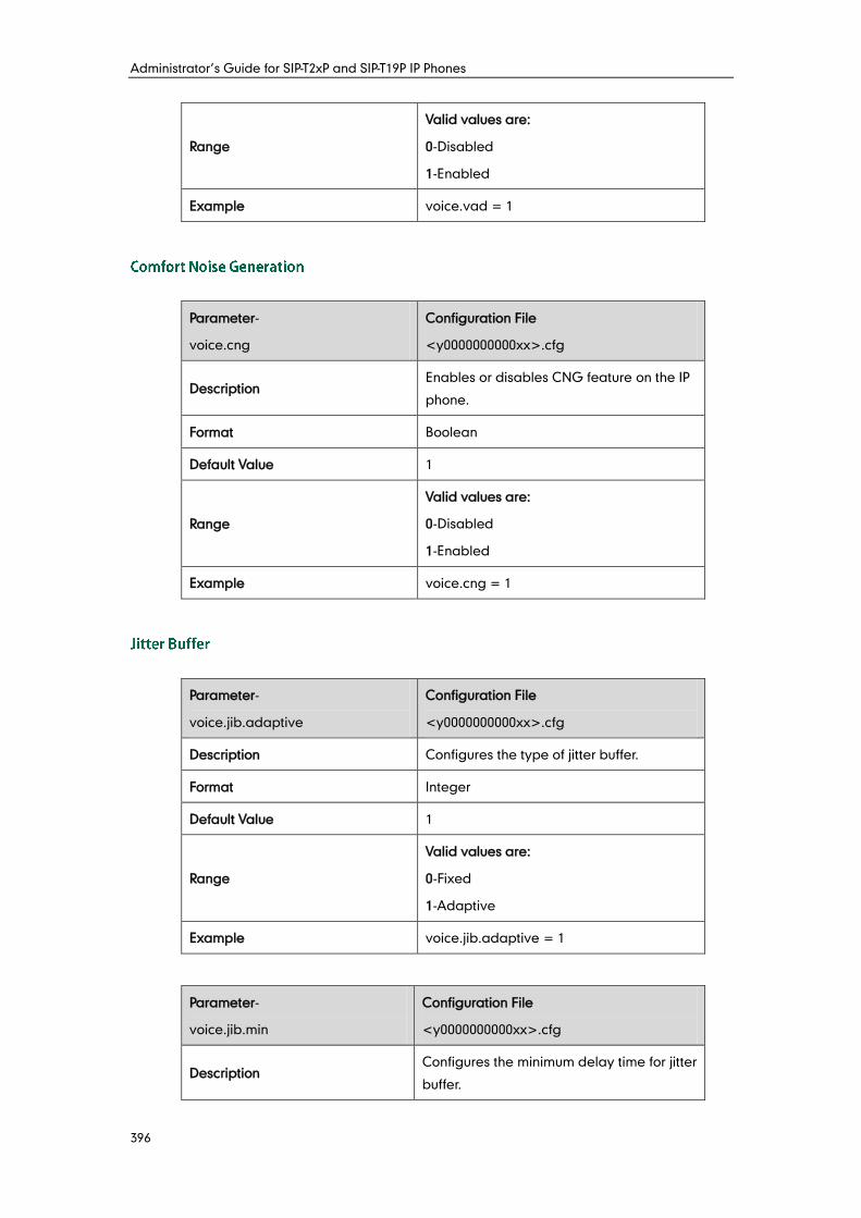
Administrator’s Guide for SIP-T2xP and SIP-T19P IP Phones
396
Range
Valid values are:
0-Disabled
1-Enabled
Example voice.vad = 1
Parameter-
voice.cng
Configuration File
<y0000000000xx>.cfg
Description Enables or disables CNG feature on the IP
phone.
Format Boolean
Default Value 1
Range
Valid values are:
0-Disabled
1-Enabled
Example voice.cng = 1
Parameter-
voice.jib.adaptive
Configuration File
<y0000000000xx>.cfg
Description Configures the type of jitter buffer.
Format Integer
Default Value 1
Range
Valid values are:
0-Fixed
1-Adaptive
Example voice.jib.adaptive = 1
Parameter-
voice.jib.min
Configuration File
<y0000000000xx>.cfg
Description Configures the minimum delay time for jitter
buffer.
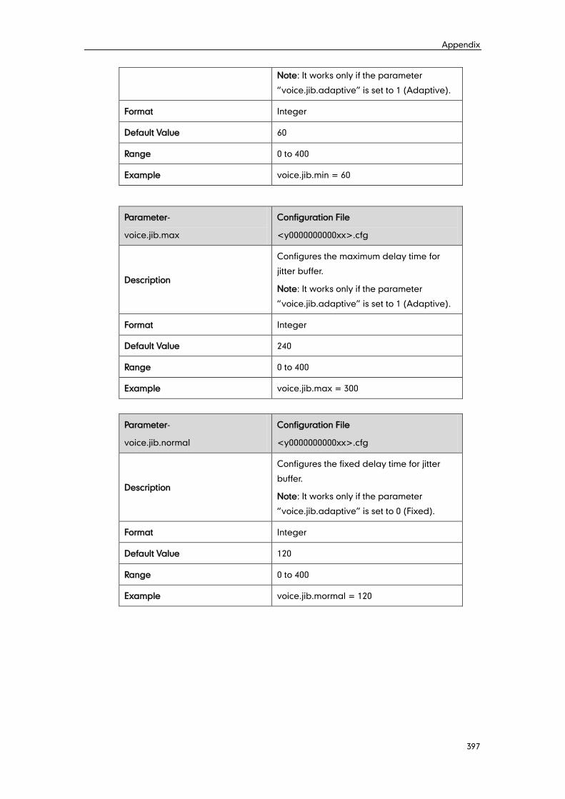
Appendix
397
Note: It works only if the parameter
“voice.jib.adaptive” is set to 1 (Adaptive).
Format Integer
Default Value 60
Range 0 to 400
Example voice.jib.min = 60
Parameter-
voice.jib.max
Configuration File
<y0000000000xx>.cfg
Description
Configures the maximum delay time for
jitter buffer.
Note: It works only if the parameter
“voice.jib.adaptive” is set to 1 (Adaptive).
Format Integer
Default Value 240
Range 0 to 400
Example voice.jib.max = 300
Parameter-
voice.jib.normal
Configuration File
<y0000000000xx>.cfg
Description
Configures the fixed delay time for jitter
buffer.
Note: It works only if the parameter
“voice.jib.adaptive” is set to 0 (Fixed).
Format Integer
Default Value 120
Range 0 to 400
Example voice.jib.mormal = 120
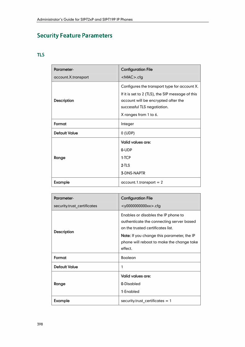
Administrator’s Guide for SIP-T2xP and SIP-T19P IP Phones
398
Parameter-
account.X.transport
Configuration File
<MAC>.cfg
Description
Configures the transport type for account X.
If it is set to 2 (TLS), the SIP message of this
account will be encrypted after the
successful TLS negotiation.
X ranges from 1 to 6.
Format Integer
Default Value 0 (UDP)
Range
Valid values are:
0-UDP
1-TCP
2-TLS
3-DNS-NAPTR
Example account.1.transport = 2
Parameter-
security.trust_certificates
Configuration File
<y0000000000xx>.cfg
Description
Enables or disables the IP phone to
authenticate the connecting server based
on the trusted certificates list.
Note: If you change this parameter, the IP
phone will reboot to make the change take
effect.
Format Boolean
Default Value 1
Range
Valid values are:
0-Disabled
1-Enabled
Example security.trust_certificates = 1
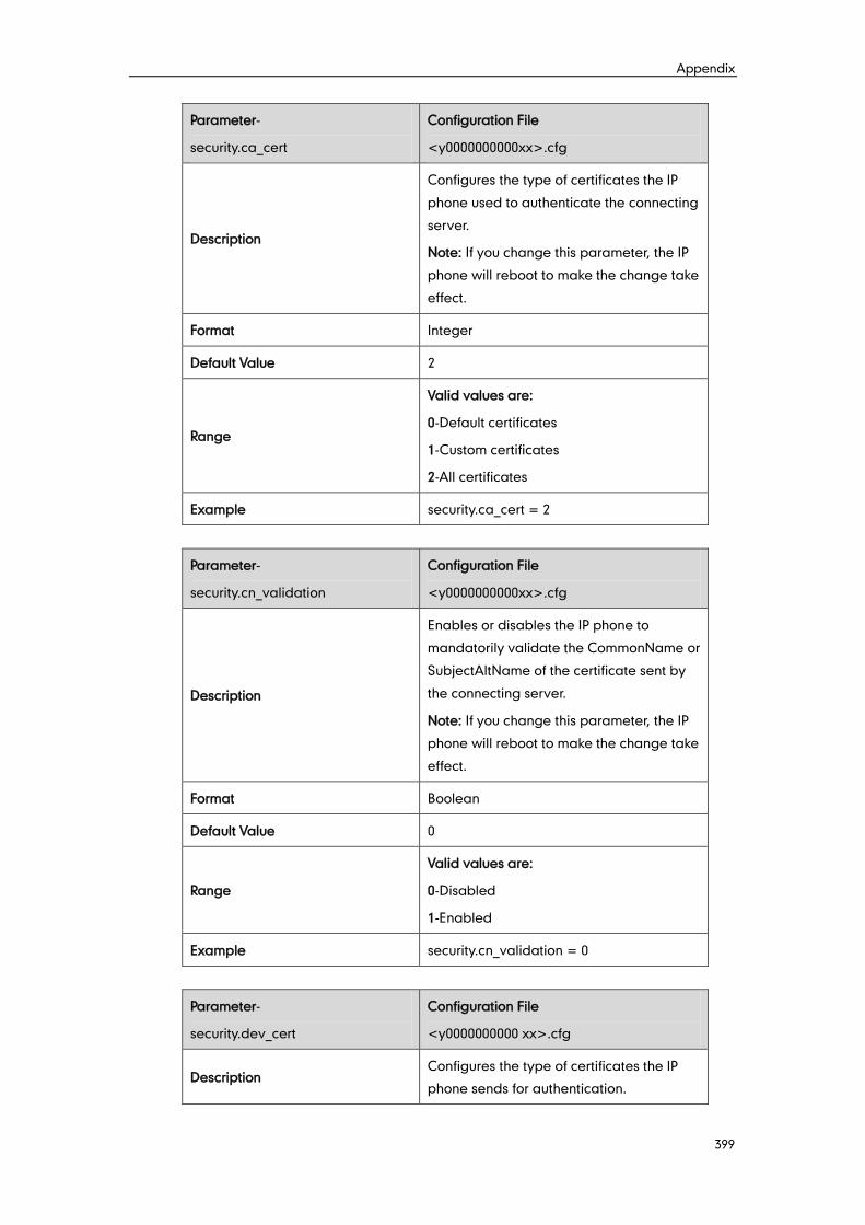
Appendix
399
Parameter-
security.ca_cert
Configuration File
<y0000000000xx>.cfg
Description
Configures the type of certificates the IP
phone used to authenticate the connecting
server.
Note: If you change this parameter, the IP
phone will reboot to make the change take
effect.
Format Integer
Default Value 2
Range
Valid values are:
0-Default certificates
1-Custom certificates
2-All certificates
Example security.ca_cert = 2
Parameter-
security.cn_validation
Configuration File
<y0000000000xx>.cfg
Description
Enables or disables the IP phone to
mandatorily validate the CommonName or
SubjectAltName of the certificate sent by
the connecting server.
Note: If you change this parameter, the IP
phone will reboot to make the change take
effect.
Format Boolean
Default Value 0
Range
Valid values are:
0-Disabled
1-Enabled
Example security.cn_validation = 0
Parameter-
security.dev_cert
Configuration File
<y0000000000 xx>.cfg
Description Configures the type of certificates the IP
phone sends for authentication.
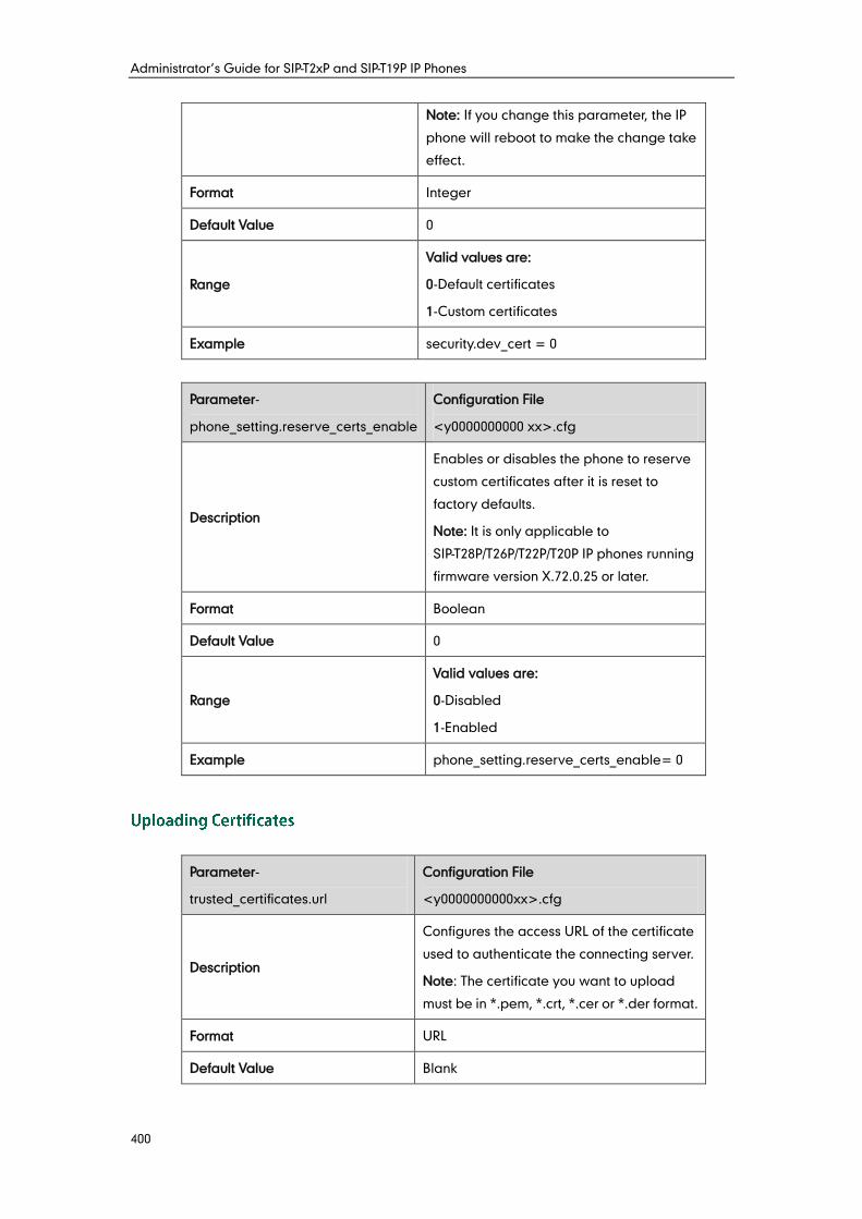
Administrator’s Guide for SIP-T2xP and SIP-T19P IP Phones
400
Note: If you change this parameter, the IP
phone will reboot to make the change take
effect.
Format Integer
Default Value 0
Range
Valid values are:
0-Default certificates
1-Custom certificates
Example security.dev_cert = 0
Parameter-
phone_setting.reserve_certs_enable
Configuration File
<y0000000000 xx>.cfg
Description
Enables or disables the phone to reserve
custom certificates after it is reset to
factory defaults.
Note: It is only applicable to
SIP-T28P/T26P/T22P/T20P IP phones running
firmware version X.72.0.25 or later.
Format Boolean
Default Value 0
Range
Valid values are:
0-Disabled
1-Enabled
Example phone_setting.reserve_certs_enable= 0
Parameter-
trusted_certificates.url
Configuration File
<y0000000000xx>.cfg
Description
Configures the access URL of the certificate
used to authenticate the connecting server.
Note: The certificate you want to upload
must be in *.pem, *.crt, *.cer or *.der format.
Format URL
Default Value Blank
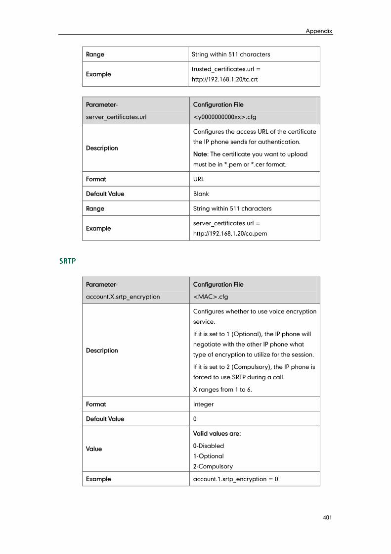
Appendix
401
Range String within 511 characters
Example trusted_certificates.url =
http://192.168.1.20/tc.crt
Parameter-
server_certificates.url
Configuration File
<y0000000000xx>.cfg
Description
Configures the access URL of the certificate
the IP phone sends for authentication.
Note: The certificate you want to upload
must be in *.pem or *.cer format.
Format URL
Default Value Blank
Range String within 511 characters
Example server_certificates.url =
http://192.168.1.20/ca.pem
Parameter-
account.X.srtp_encryption
Configuration File
<MAC>.cfg
Description
Configures whether to use voice encryption
service.
If it is set to 1 (Optional), the IP phone will
negotiate with the other IP phone what
type of encryption to utilize for the session.
If it is set to 2 (Compulsory), the IP phone is
forced to use SRTP during a call.
X ranges from 1 to 6.
Format Integer
Default Value 0
Value
Valid values are:
0-Disabled
1-Optional
2-Compulsory
Example account.1.srtp_encryption = 0
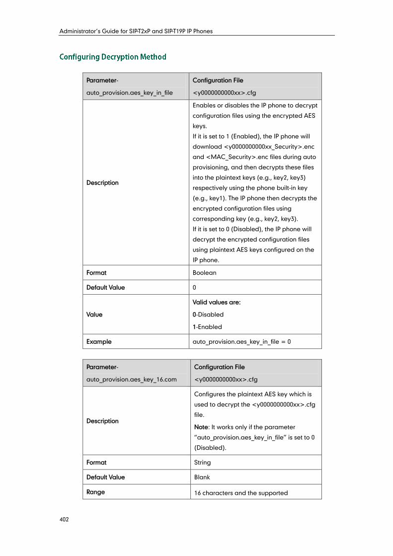
Administrator’s Guide for SIP-T2xP and SIP-T19P IP Phones
402
Parameter-
auto_provision.aes_key_in_file
Configuration File
<y0000000000xx>.cfg
Description
Enables or disables the IP phone to decrypt
configuration files using the encrypted AES
keys.
If it is set to 1 (Enabled), the IP phone will
download <y0000000000xx_Security>.enc
and <MAC_Security>.enc files during auto
provisioning, and then decrypts these files
into the plaintext keys (e.g., key2, key3)
respectively using the phone built-in key
(e.g., key1). The IP phone then decrypts the
encrypted configuration files using
corresponding key (e.g., key2, key3).
If it is set to 0 (Disabled), the IP phone will
decrypt the encrypted configuration files
using plaintext AES keys configured on the
IP phone.
Format Boolean
Default Value 0
Value
Valid values are:
0-Disabled
1-Enabled
Example auto_provision.aes_key_in_file = 0
Parameter-
auto_provision.aes_key_16.com
Configuration File
<y0000000000xx>.cfg
Description
Configures the plaintext AES key which is
used to decrypt the <y0000000000xx>.cfg
file.
Note: It works only if the parameter
“auto_provision.aes_key_in_file” is set to 0
(Disabled).
Format String
Default Value Blank
Range 16 characters and the supported
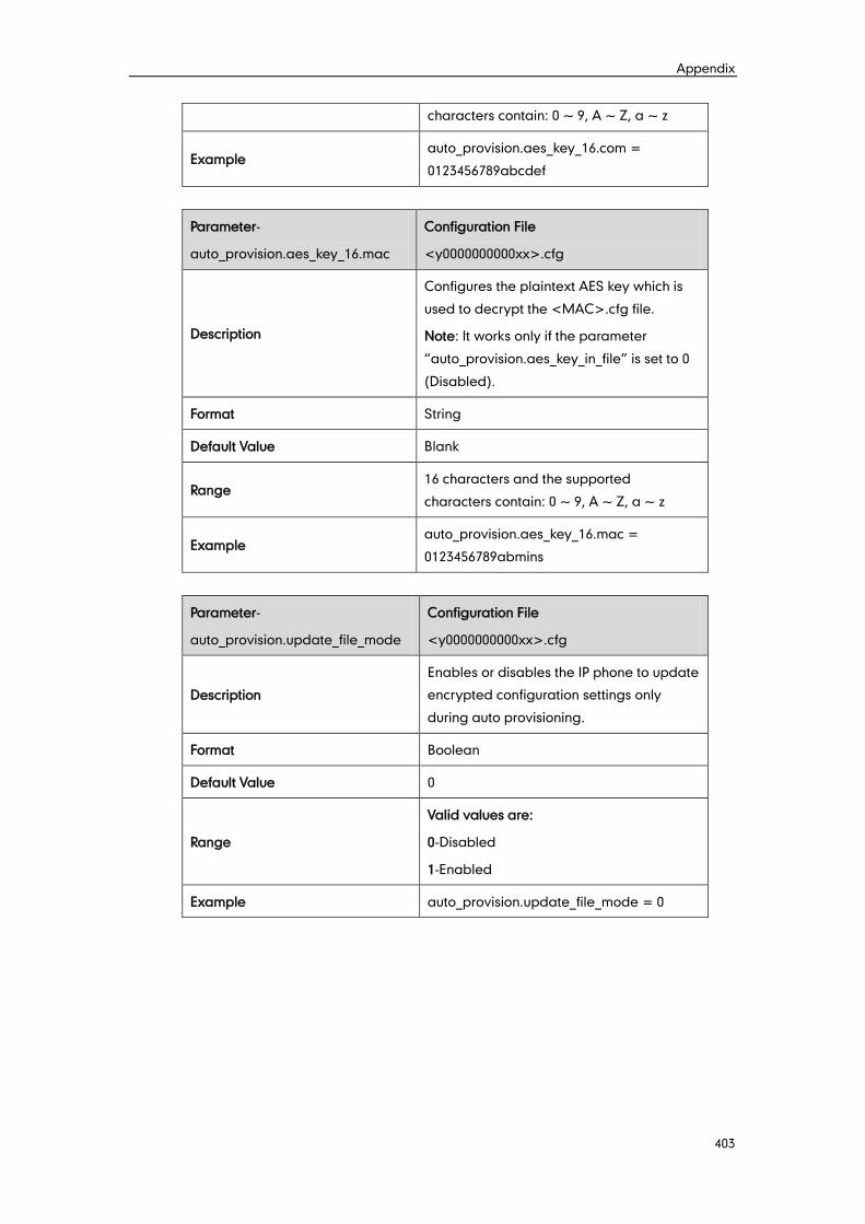
Appendix
403
characters contain: 0 ~ 9, A ~ Z, a ~ z
Example auto_provision.aes_key_16.com =
0123456789abcdef
Parameter-
auto_provision.aes_key_16.mac
Configuration File
<y0000000000xx>.cfg
Description
Configures the plaintext AES key which is
used to decrypt the <MAC>.cfg file.
Note: It works only if the parameter
“auto_provision.aes_key_in_file” is set to 0
(Disabled).
Format String
Default Value Blank
Range 16 characters and the supported
characters contain: 0 ~ 9, A ~ Z, a ~ z
Example auto_provision.aes_key_16.mac =
0123456789abmins
Parameter-
auto_provision.update_file_mode
Configuration File
<y0000000000xx>.cfg
Description
Enables or disables the IP phone to update
encrypted configuration settings only
during auto provisioning.
Format Boolean
Default Value 0
Range
Valid values are:
0-Disabled
1-Enabled
Example auto_provision.update_file_mode = 0
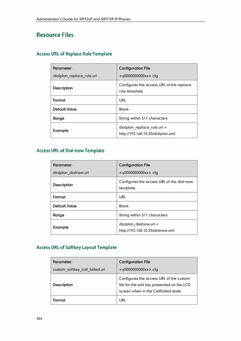
Administrator’s Guide for SIP-T2xP and SIP-T19P IP Phones
404
Parameter-
dialplan_replace_rule.url
Configuration File
<y0000000000xx>.cfg
Description Configures the access URL of the replace
rule template.
Format URL
Default Value Blank
Range String within 511 characters
Example dialplan_replace_rule.url =
http://192.168.10.25/dialplan.xml
Parameter-
dialplan_dialnow.url
Configuration File
<y0000000000xx>.cfg
Description Configures the access URL of the dial-now
template.
Format URL
Default Value Blank
Range String within 511 characters
Example dialplan_dialnow.url =
http://192.168.10.25/dialnow.xml
Parameter-
custom_softkey_call_failed.url
Configuration File
<y0000000000xx>.cfg
Description
Configures the access URL of the custom
file for the soft key presented on the LCD
screen when in the CallFailed state.
Format URL
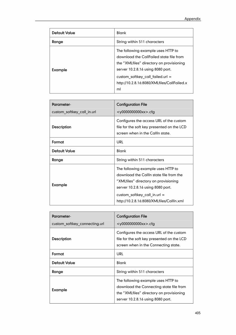
Appendix
405
Default Value Blank
Range String within 511 characters
Example
The following example uses HTTP to
download the CallFailed state file from
the “XMLfiles” directory on provisioning
server 10.2.8.16 using 8080 port.
custom_softkey_call_failed.url =
http://10.2.8.16:8080/XMLfiles/CallFailed.x
ml
Parameter-
custom_softkey_call_in.url
Configuration File
<y0000000000xx>.cfg
Description
Configures the access URL of the custom
file for the soft key presented on the LCD
screen when in the CallIn state.
Format URL
Default Value Blank
Range String within 511 characters
Example
The following example uses HTTP to
download the CallIn state file from the
“XMLfiles” directory on provisioning
server 10.2.8.16 using 8080 port.
custom_softkey_call_in.url =
http://10.2.8.16:8080/XMLfiles/CallIn.xml
Parameter-
custom_softkey_connecting.url
Configuration File
<y0000000000xx>.cfg
Description
Configures the access URL of the custom
file for the soft key presented on the LCD
screen when in the Connecting state.
Format URL
Default Value Blank
Range String within 511 characters
Example
The following example uses HTTP to
download the Connecting state file from
the “XMLfiles” directory on provisioning
server 10.2.8.16 using 8080 port.
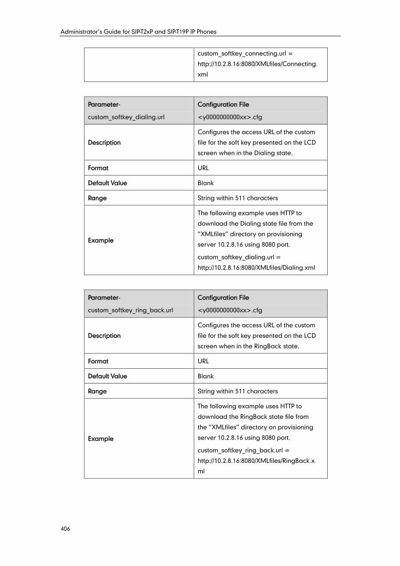
Administrator’s Guide for SIP-T2xP and SIP-T19P IP Phones
406
custom_softkey_connecting.url =
http://10.2.8.16:8080/XMLfiles/Connecting.
xml
Parameter-
custom_softkey_dialing.url
Configuration File
<y0000000000xx>.cfg
Description
Configures the access URL of the custom
file for the soft key presented on the LCD
screen when in the Dialing state.
Format URL
Default Value Blank
Range String within 511 characters
Example
The following example uses HTTP to
download the Dialing state file from the
“XMLfiles” directory on provisioning
server 10.2.8.16 using 8080 port.
custom_softkey_dialing.url =
http://10.2.8.16:8080/XMLfiles/Dialing.xml
Parameter-
custom_softkey_ring_back.url
Configuration File
<y0000000000xx>.cfg
Description
Configures the access URL of the custom
file for the soft key presented on the LCD
screen when in the RingBack state.
Format URL
Default Value Blank
Range String within 511 characters
Example
The following example uses HTTP to
download the RingBack state file from
the “XMLfiles” directory on provisioning
server 10.2.8.16 using 8080 port.
custom_softkey_ring_back.url =
http://10.2.8.16:8080/XMLfiles/RingBack.x
ml
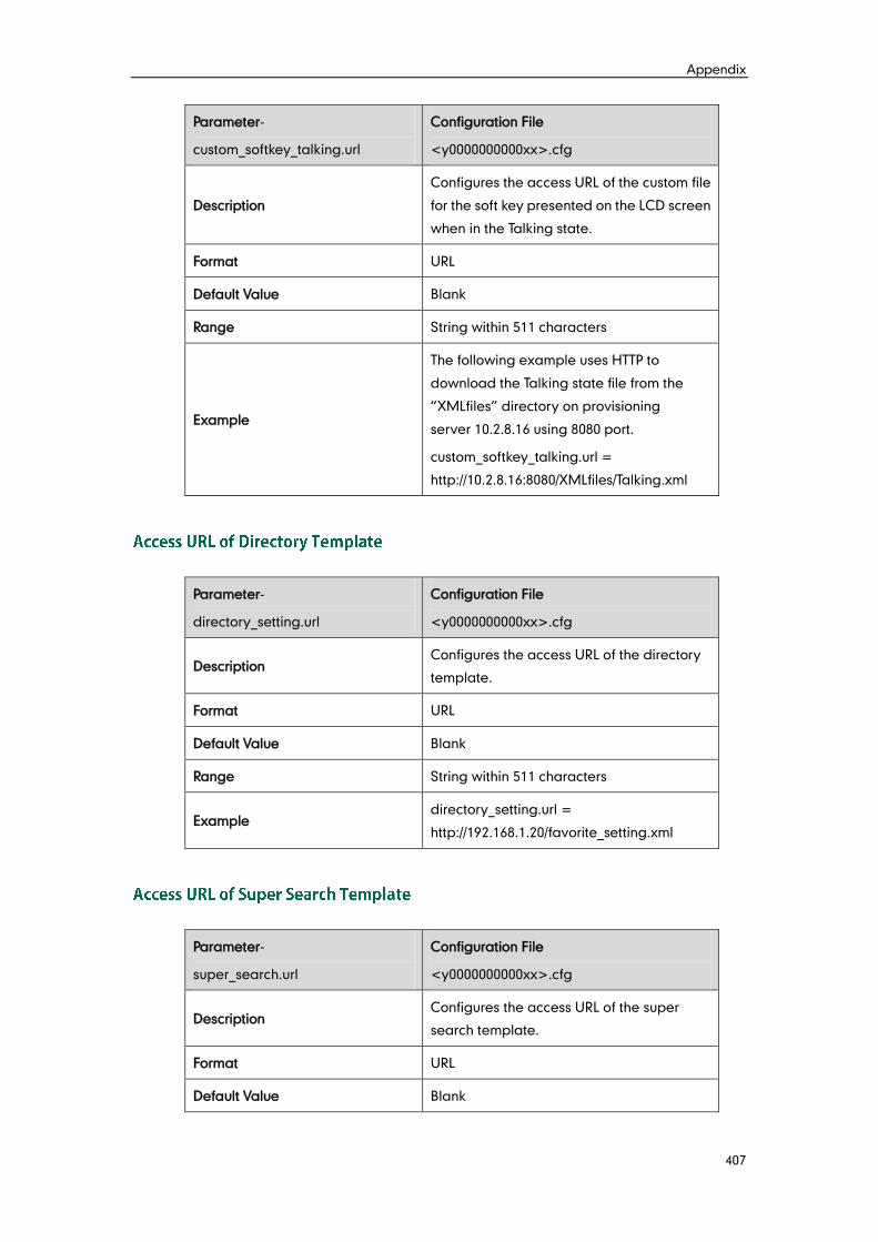
Appendix
407
Parameter-
custom_softkey_talking.url
Configuration File
<y0000000000xx>.cfg
Description
Configures the access URL of the custom file
for the soft key presented on the LCD screen
when in the Talking state.
Format URL
Default Value Blank
Range String within 511 characters
Example
The following example uses HTTP to
download the Talking state file from the
“XMLfiles” directory on provisioning
server 10.2.8.16 using 8080 port.
custom_softkey_talking.url =
http://10.2.8.16:8080/XMLfiles/Talking.xml
Parameter-
directory_setting.url
Configuration File
<y0000000000xx>.cfg
Description Configures the access URL of the directory
template.
Format URL
Default Value Blank
Range String within 511 characters
Example directory_setting.url =
http://192.168.1.20/favorite_setting.xml
Parameter-
super_search.url
Configuration File
<y0000000000xx>.cfg
Description Configures the access URL of the super
search template.
Format URL
Default Value Blank
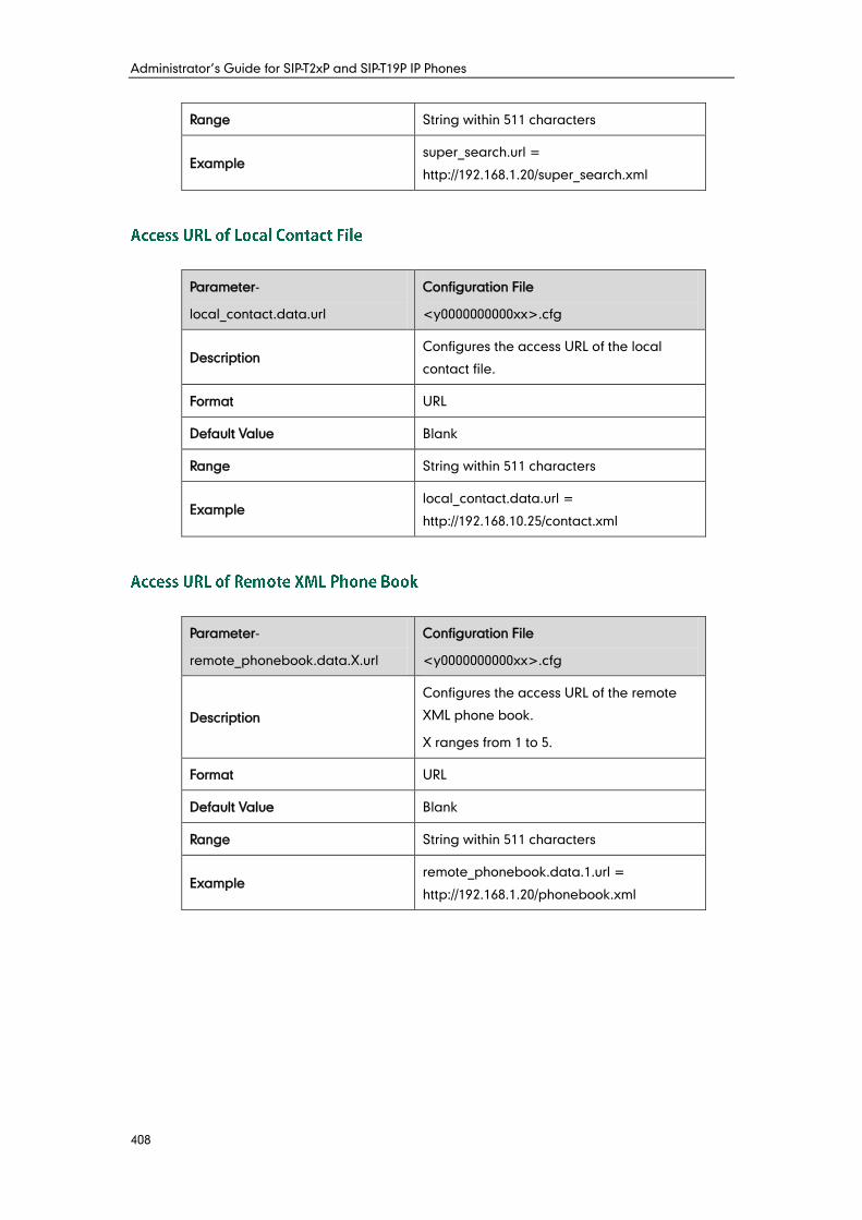
Administrator’s Guide for SIP-T2xP and SIP-T19P IP Phones
408
Range String within 511 characters
Example super_search.url =
http://192.168.1.20/super_search.xml
Parameter-
local_contact.data.url
Configuration File
<y0000000000xx>.cfg
Description Configures the access URL of the local
contact file.
Format URL
Default Value Blank
Range String within 511 characters
Example local_contact.data.url =
http://192.168.10.25/contact.xml
Parameter-
remote_phonebook.data.X.url
Configuration File
<y0000000000xx>.cfg
Description
Configures the access URL of the remote
XML phone book.
X ranges from 1 to 5.
Format URL
Default Value Blank
Range String within 511 characters
Example remote_phonebook.data.1.url =
http://192.168.1.20/phonebook.xml
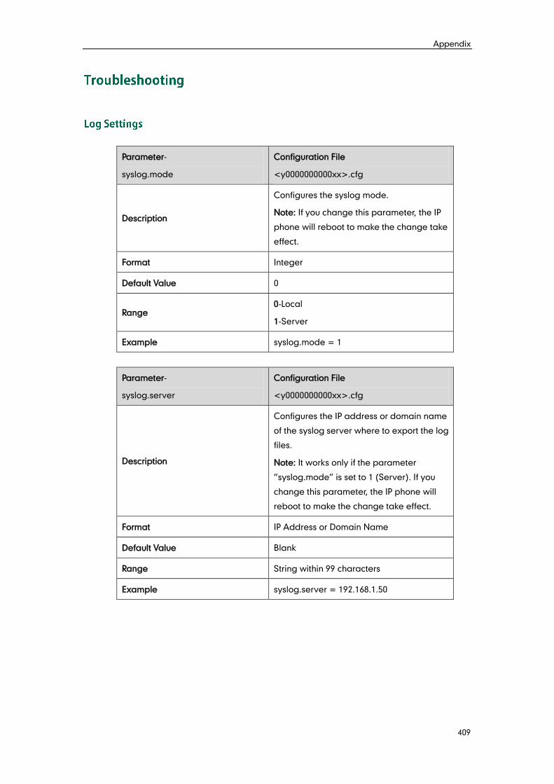
Appendix
409
Parameter-
syslog.mode
Configuration File
<y0000000000xx>.cfg
Description
Configures the syslog mode.
Note: If you change this parameter, the IP
phone will reboot to make the change take
effect.
Format Integer
Default Value 0
Range 0-Local
1-Server
Example syslog.mode = 1
Parameter-
syslog.server
Configuration File
<y0000000000xx>.cfg
Description
Configures the IP address or domain name
of the syslog server where to export the log
files.
Note: It works only if the parameter
“syslog.mode” is set to 1 (Server). If you
change this parameter, the IP phone will
reboot to make the change take effect.
Format IP Address or Domain Name
Default Value Blank
Range String within 99 characters
Example syslog.server = 192.168.1.50
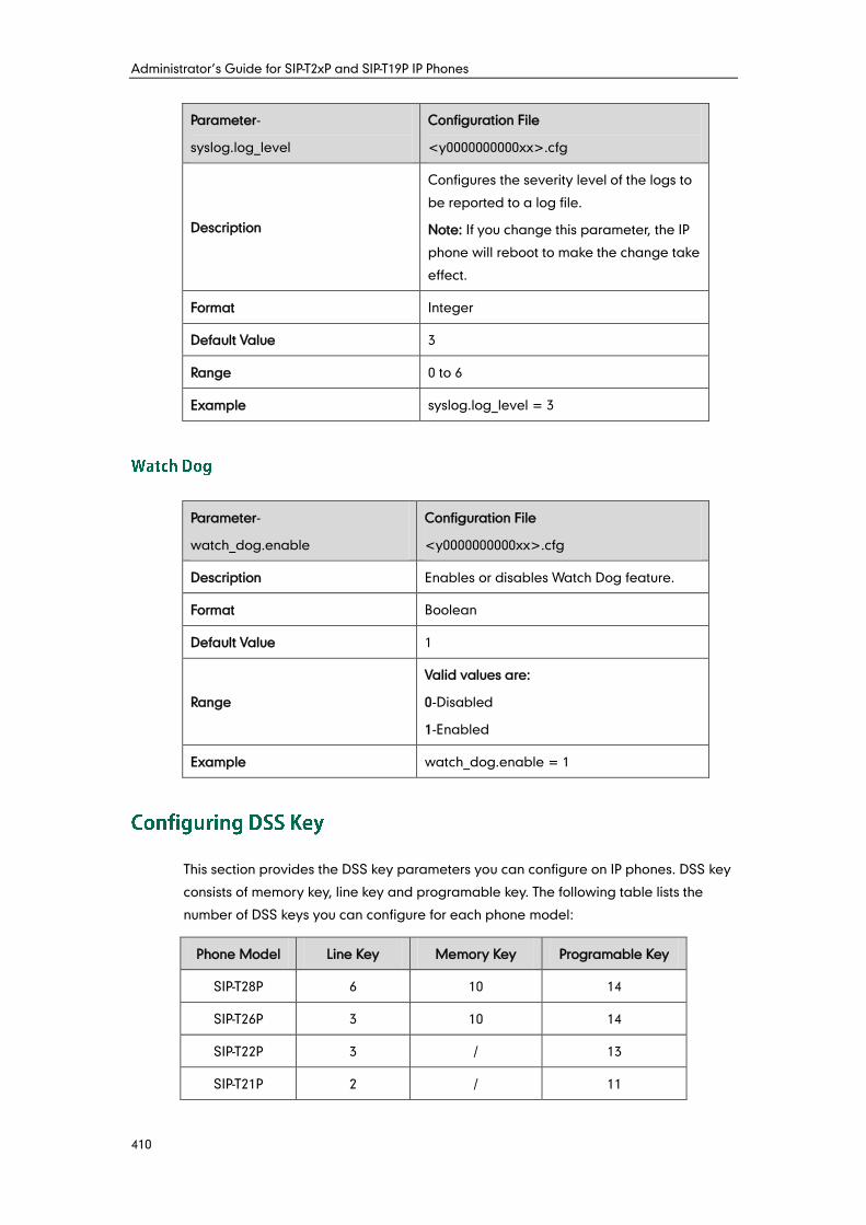
Administrator’s Guide for SIP-T2xP and SIP-T19P IP Phones
410
Parameter-
syslog.log_level
Configuration File
<y0000000000xx>.cfg
Description
Configures the severity level of the logs to
be reported to a log file.
Note: If you change this parameter, the IP
phone will reboot to make the change take
effect.
Format Integer
Default Value 3
Range 0 to 6
Example syslog.log_level = 3
Parameter-
watch_dog.enable
Configuration File
<y0000000000xx>.cfg
Description Enables or disables Watch Dog feature.
Format Boolean
Default Value 1
Range
Valid values are:
0-Disabled
1-Enabled
Example watch_dog.enable = 1
This section provides the DSS key parameters you can configure on IP phones. DSS key
consists of memory key, line key and programable key. The following table lists the
number of DSS keys you can configure for each phone model:
Phone Model Line Key Memory Key Programable Key
SIP-T28P 6 10 14
SIP-T26P 3 10 14
SIP-T22P 3 / 13
SIP-T21P 2 / 11
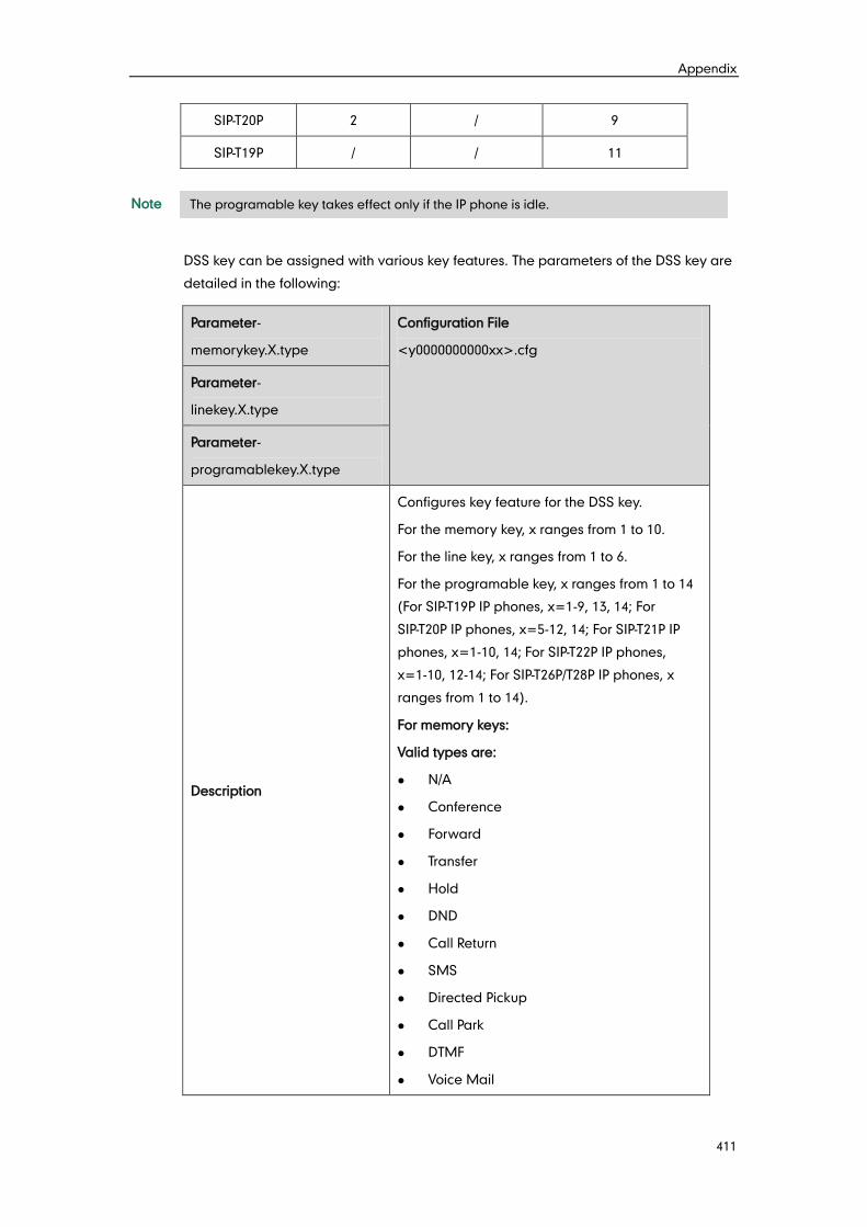
Appendix
411
SIP-T20P 2 / 9
SIP-T19P / / 11
Note
DSS key can be assigned with various key features. The parameters of the DSS key are
detailed in the following:
Parameter-
memorykey.X.type
Configuration File
<y0000000000xx>.cfg
Parameter-
linekey.X.type
Parameter-
programablekey.X.type
Description
Configures key feature for the DSS key.
For the memory key, x ranges from 1 to 10.
For the line key, x ranges from 1 to 6.
For the programable key, x ranges from 1 to 14
(For SIP-T19P IP phones, x=1-9, 13, 14; For
SIP-T20P IP phones, x=5-12, 14; For SIP-T21P IP
phones, x=1-10, 14; For SIP-T22P IP phones,
x=1-10, 12-14; For SIP-T26P/T28P IP phones, x
ranges from 1 to 14).
For memory keys:
Valid types are:
N/A
Conference
Forward
Transfer
Hold
DND
Call Return
SMS
Directed Pickup
Call Park
DTMF
Voice Mail
The programable key takes effect only if the IP phone is idle.
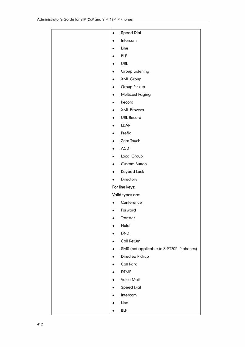
Administrator’s Guide for SIP-T2xP and SIP-T19P IP Phones
412
Speed Dial
Intercom
Line
BLF
URL
Group Listening
XML Group
Group Pickup
Multicast Paging
Record
XML Browser
URL Record
LDAP
Prefix
Zero Touch
ACD
Local Group
Custom Button
Keypad Lock
Directory
For line keys:
Valid types are:
Conference
Forward
Transfer
Hold
DND
Call Return
SMS (not applicable to SIP-T20P IP phones)
Directed Pickup
Call Park
DTMF
Voice Mail
Speed Dial
Intercom
Line
BLF
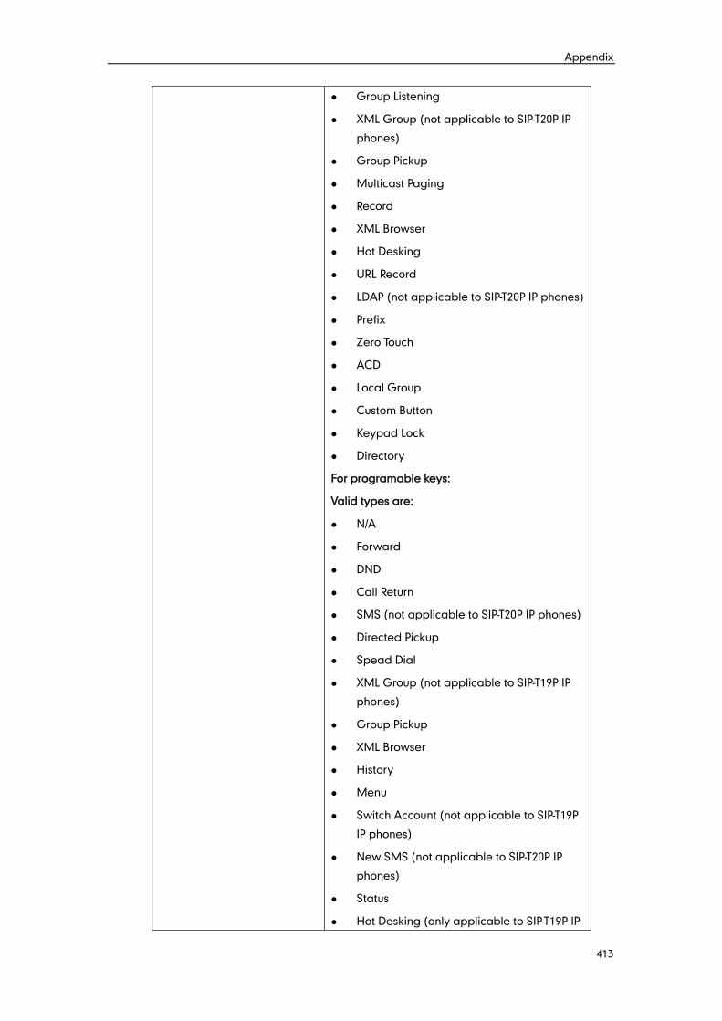
Appendix
413
Group Listening
XML Group (not applicable to SIP-T20P IP
phones)
Group Pickup
Multicast Paging
Record
XML Browser
Hot Desking
URL Record
LDAP (not applicable to SIP-T20P IP phones)
Prefix
Zero Touch
ACD
Local Group
Custom Button
Keypad Lock
Directory
For programable keys:
Valid types are:
N/A
Forward
DND
Call Return
SMS (not applicable to SIP-T20P IP phones)
Directed Pickup
Spead Dial
XML Group (not applicable to SIP-T19P IP
phones)
Group Pickup
XML Browser
History
Menu
Switch Account (not applicable to SIP-T19P
IP phones)
New SMS (not applicable to SIP-T20P IP
phones)
Status
Hot Desking (only applicable to SIP-T19P IP
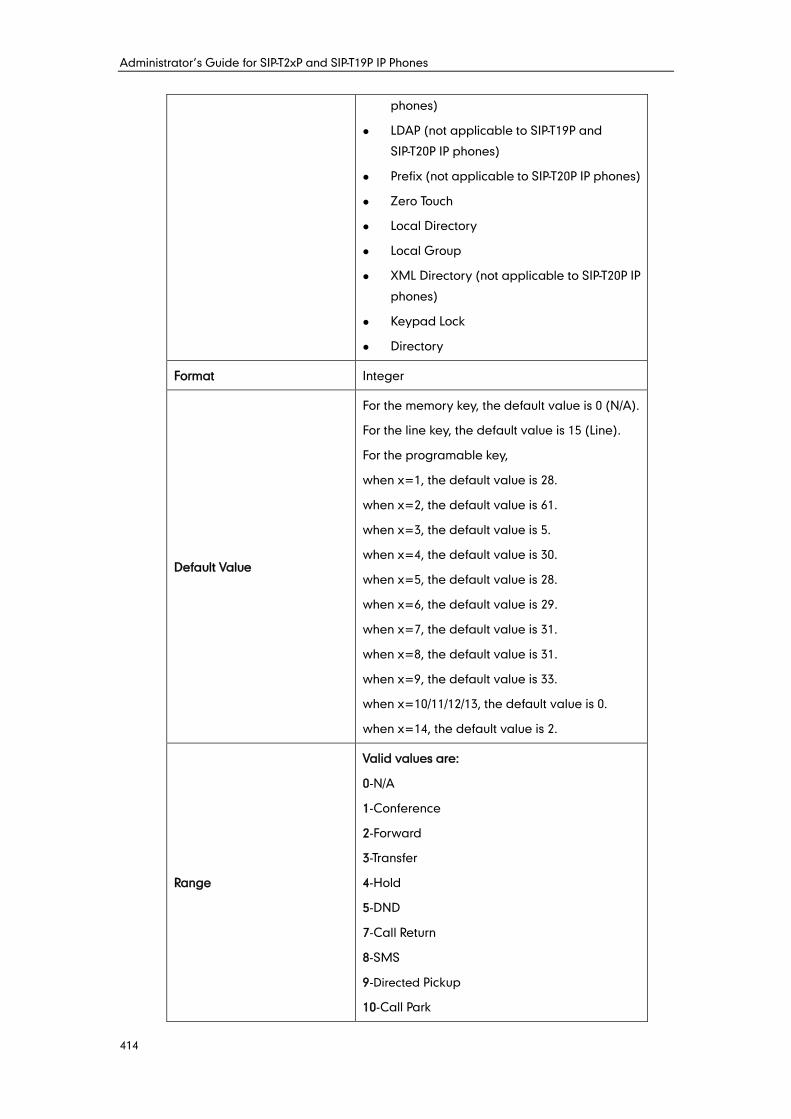
Administrator’s Guide for SIP-T2xP and SIP-T19P IP Phones
414
phones)
LDAP (not applicable to SIP-T19P and
SIP-T20P IP phones)
Prefix (not applicable to SIP-T20P IP phones)
Zero Touch
Local Directory
Local Group
XML Directory (not applicable to SIP-T20P IP
phones)
Keypad Lock
Directory
Format Integer
Default Value
For the memory key, the default value is 0 (N/A).
For the line key, the default value is 15 (Line).
For the programable key,
when x=1, the default value is 28.
when x=2, the default value is 61.
when x=3, the default value is 5.
when x=4, the default value is 30.
when x=5, the default value is 28.
when x=6, the default value is 29.
when x=7, the default value is 31.
when x=8, the default value is 31.
when x=9, the default value is 33.
when x=10/11/12/13, the default value is 0.
when x=14, the default value is 2.
Range
Valid values are:
0-N/A
1-Conference
2-Forward
3-Transfer
4-Hold
5-DND
7-Call Return
8-SMS
9-Directed Pickup
10-Call Park
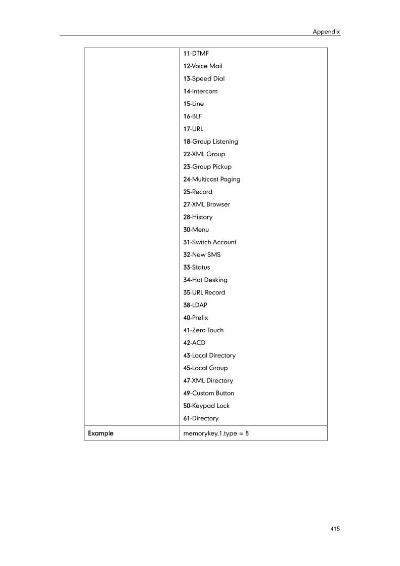
Appendix
415
11-DTMF
12-Voice Mail
13-Speed Dial
14-Intercom
15-Line
16-BLF
17-URL
18-Group Listening
22-XML Group
23-Group Pickup
24-Multicast Paging
25-Record
27-XML Browser
28-History
30-Menu
31-Switch Account
32-New SMS
33-Status
34-Hot Desking
35-URL Record
38-LDAP
40-Prefix
41-Zero Touch
42-ACD
43-Local Directory
45-Local Group
47-XML Directory
49-Custom Button
50-Keypad Lock
61-Directory
Example memorykey.1.type = 8
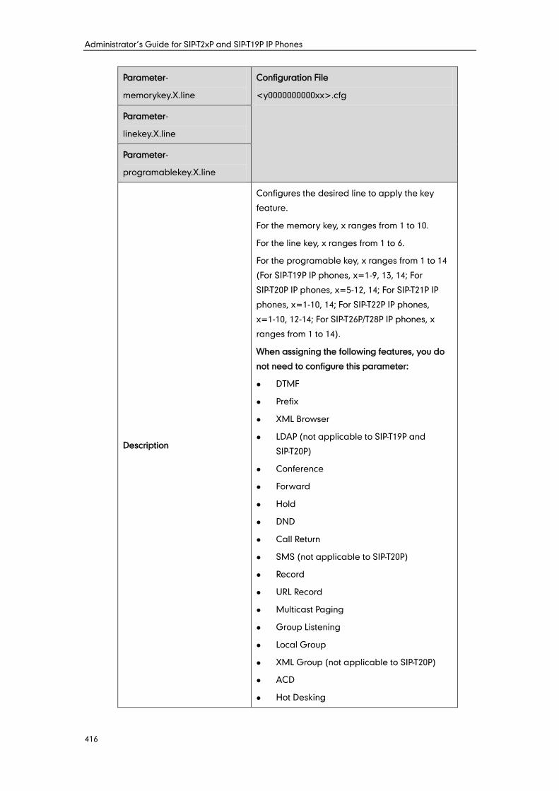
Administrator’s Guide for SIP-T2xP and SIP-T19P IP Phones
416
Parameter-
memorykey.X.line
Configuration File
<y0000000000xx>.cfg
Parameter-
linekey.X.line
Parameter-
programablekey.X.line
Description
Configures the desired line to apply the key
feature.
For the memory key, x ranges from 1 to 10.
For the line key, x ranges from 1 to 6.
For the programable key, x ranges from 1 to 14
(For SIP-T19P IP phones, x=1-9, 13, 14; For
SIP-T20P IP phones, x=5-12, 14; For SIP-T21P IP
phones, x=1-10, 14; For SIP-T22P IP phones,
x=1-10, 12-14; For SIP-T26P/T28P IP phones, x
ranges from 1 to 14).
When assigning the following features, you do
not need to configure this parameter:
DTMF
Prefix
XML Browser
LDAP (not applicable to SIP-T19P and
SIP-T20P)
Conference
Forward
Hold
DND
Call Return
SMS (not applicable to SIP-T20P)
Record
URL Record
Multicast Paging
Group Listening
Local Group
XML Group (not applicable to SIP-T20P)
ACD
Hot Desking
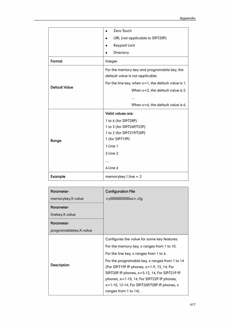
Appendix
417
Zero Touch
URL (not applicable to SIP-T20P)
Keypad Lock
Directory
Format Integer
Default Value
For the memory key and programable key, the
default value is not applicable.
For the line key, when x=1, the default value is 1.
When x=2, the default value is 2.
…
When x=6, the default value is 6.
Range
Valid values are:
1 to 6 (for SIP-T28P)
1 to 3 (for SIP-T26P/T22P)
1 to 2 (for SIP-T21P/T20P)
1 (for SIP-T19P)
1-Line 1
2-Line 2
…
6-Line 6
Example memorykey.1.line = 2
Parameter-
memorykey.X.value
Configuration File
<y0000000000xx>.cfg
Parameter-
linekey.X.value
Parameter-
programablekey.X.value
Description
Configures the value for some key features.
For the memory key, x ranges from 1 to 10.
For the line key, x ranges from 1 to 6.
For the programable key, x ranges from 1 to 14
(For SIP-T19P IP phones, x=1-9, 13, 14; For
SIP-T20P IP phones, x=5-12, 14; For SIP-T21P IP
phones, x=1-10, 14; For SIP-T22P IP phones,
x=1-10, 12-14; For SIP-T26P/T28P IP phones, x
ranges from 1 to 14).
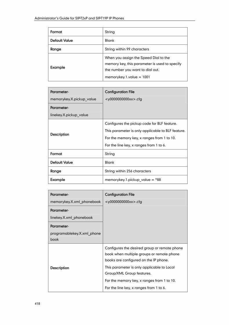
Administrator’s Guide for SIP-T2xP and SIP-T19P IP Phones
418
Format String
Default Value Blank
Range String within 99 characters
Example
When you assign the Speed Dial to the
memory key, this parameter is used to specify
the number you want to dial out.
memorykey.1.value = 1001
Parameter-
memorykey.X.pickup_value
Configuration File
<y0000000000xx>.cfg
Parameter-
linekey.X.pickup_value
Description
Configures the pickup code for BLF feature.
This parameter is only applicable to BLF feature.
For the memory key, x ranges from 1 to 10.
For the line key, x ranges from 1 to 6.
Format String
Default Value Blank
Range String within 256 characters
Example memorykey.1.pickup_value = *88
Parameter-
memorykey.X.xml_phonebook
Configuration File
<y0000000000xx>.cfg
Parameter-
linekey.X.xml_phonebook
Parameter-
programablekey.X.xml_phone
book
Description
Configures the desired group or remote phone
book when multiple groups or remote phone
books are configured on the IP phone.
This parameter is only applicable to Local
Group/XML Group features.
For the memory key, x ranges from 1 to 10.
For the line key, x ranges from 1 to 6.
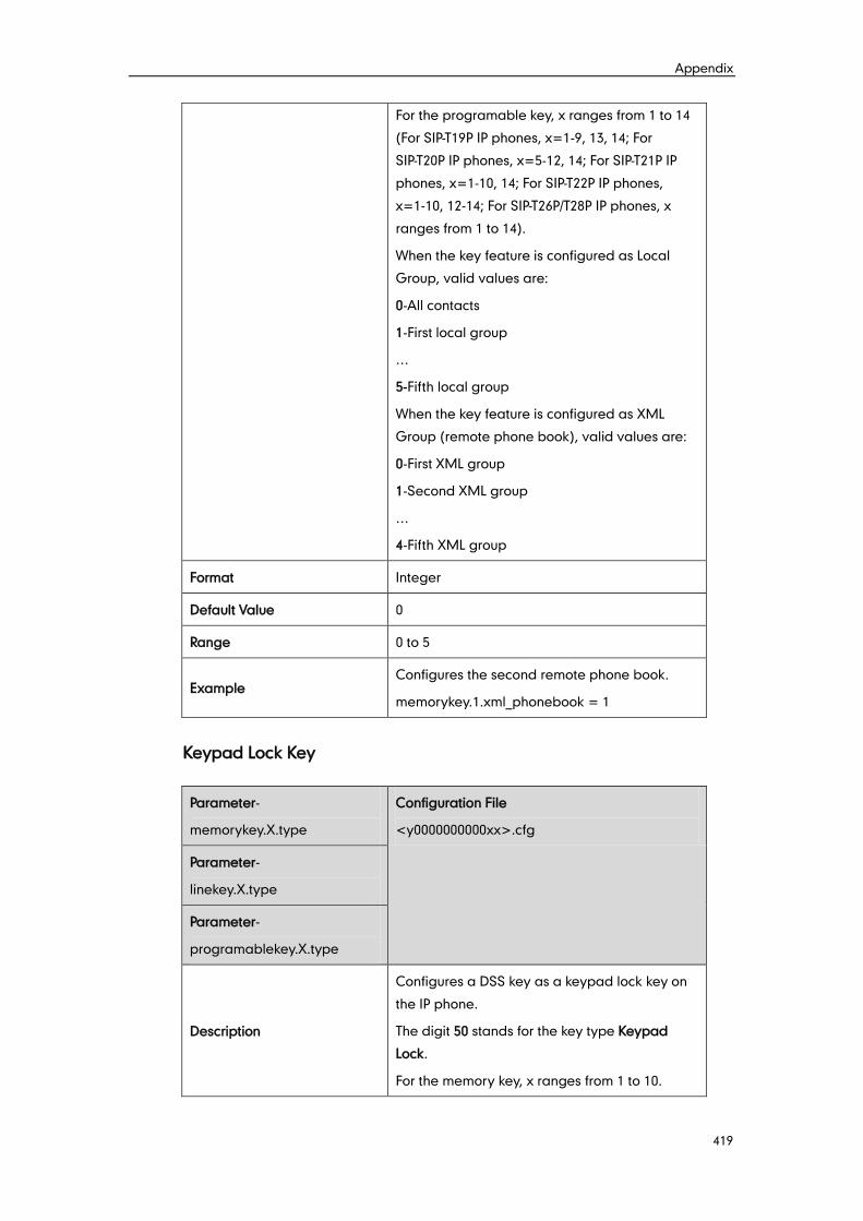
Appendix
419
For the programable key, x ranges from 1 to 14
(For SIP-T19P IP phones, x=1-9, 13, 14; For
SIP-T20P IP phones, x=5-12, 14; For SIP-T21P IP
phones, x=1-10, 14; For SIP-T22P IP phones,
x=1-10, 12-14; For SIP-T26P/T28P IP phones, x
ranges from 1 to 14).
When the key feature is configured as Local
Group, valid values are:
0-All contacts
1-First local group
…
5-Fifth local group
When the key feature is configured as XML
Group (remote phone book), valid values are:
0-First XML group
1-Second XML group
…
4-Fifth XML group
Format Integer
Default Value 0
Range 0 to 5
Example Configures the second remote phone book.
memorykey.1.xml_phonebook = 1
Keypad Lock Key
Parameter-
memorykey.X.type
Configuration File
<y0000000000xx>.cfg
Parameter-
linekey.X.type
Parameter-
programablekey.X.type
Description
Configures a DSS key as a keypad lock key on
the IP phone.
The digit 50 stands for the key type Keypad
Lock.
For the memory key, x ranges from 1 to 10.
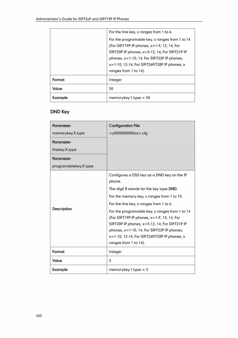
Administrator’s Guide for SIP-T2xP and SIP-T19P IP Phones
420
For the line key, x ranges from 1 to 6.
For the programable key, x ranges from 1 to 14
(For SIP-T19P IP phones, x=1-9, 13, 14; For
SIP-T20P IP phones, x=5-12, 14; For SIP-T21P IP
phones, x=1-10, 14; For SIP-T22P IP phones,
x=1-10, 12-14; For SIP-T26P/T28P IP phones, x
ranges from 1 to 14).
Format Integer
Value 50
Example memorykey.1.type = 50
DND Key
Parameter-
memorykey.X.type
Configuration File
<y0000000000xx>.cfg
Parameter-
linekey.X.type
Parameter-
programablekey.X.type
Description
Configures a DSS key as a DND key on the IP
phone.
The digit 5 stands for the key type DND.
For the memory key, x ranges from 1 to 10.
For the line key, x ranges from 1 to 6.
For the programable key, x ranges from 1 to 14
(For SIP-T19P IP phones, x=1-9, 13, 14; For
SIP-T20P IP phones, x=5-12, 14; For SIP-T21P IP
phones, x=1-10, 14; For SIP-T22P IP phones,
x=1-10, 12-14; For SIP-T26P/T28P IP phones, x
ranges from 1 to 14).
Format Integer
Value 5
Example memorykey.1.type = 5

Appendix
421
Directed Call Pickup Key
Parameter-
memorykey.X.type
Configuration File
<y0000000000xx>.cfg
Parameter-
linekey.X.type
Parameter-
programablekey.X.type
Description
Configures a DSS key as a directed call pickup
key on the IP phone.
The digit 9 stands for the key type Directed
Pickup.
For the memory key, x ranges from 1 to 10.
For the line key, x ranges from 1 to 6.
For the programable key, x ranges from 1 to 14
(For SIP-T19P IP phones, x=1-9, 13, 14; For
SIP-T20P IP phones, x=5-12, 14; For SIP-T21P IP
phones, x=1-10, 14; For SIP-T22P IP phones,
x=1-10, 12-14; For SIP-T26P/T28P IP phones, x
ranges from 1 to 14).
Format Integer
Value 9
Example memorykey.1.type = 9
Parameter-
memorykey.X.line
Configuration File
<y0000000000xx>.cfg
Parameter-
linekey.X.line
Parameter-
programablekey.X.line
Description
Configures the desired line to apply the directed
call pickup key.
For the memory key, x ranges from 1 to 10.
For the line key, x ranges from 1 to 6.
For the programable key, x ranges from 1 to 14
(For SIP-T19P IP phones, x=1-9, 13, 14; For
SIP-T20P IP phones, x=5-12, 14; For SIP-T21P IP
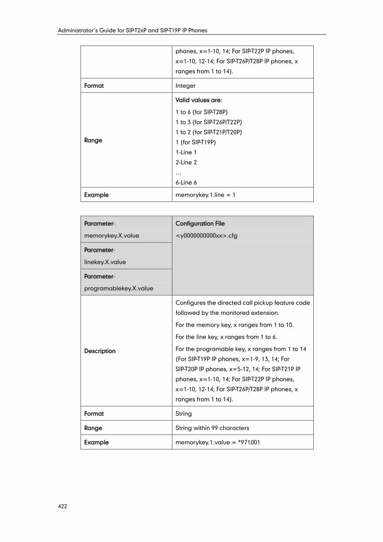
Administrator’s Guide for SIP-T2xP and SIP-T19P IP Phones
422
phones, x=1-10, 14; For SIP-T22P IP phones,
x=1-10, 12-14; For SIP-T26P/T28P IP phones, x
ranges from 1 to 14).
Format Integer
Range
Valid values are:
1 to 6 (for SIP-T28P)
1 to 3 (for SIP-T26P/T22P)
1 to 2 (for SIP-T21P/T20P)
1 (for SIP-T19P)
1-Line 1
2-Line 2
…
6-Line 6
Example memorykey.1.line = 1
Parameter-
memorykey.X.value
Configuration File
<y0000000000xx>.cfg
Parameter-
linekey.X.value
Parameter-
programablekey.X.value
Description
Configures the directed call pickup feature code
followed by the monitored extension.
For the memory key, x ranges from 1 to 10.
For the line key, x ranges from 1 to 6.
For the programable key, x ranges from 1 to 14
(For SIP-T19P IP phones, x=1-9, 13, 14; For
SIP-T20P IP phones, x=5-12, 14; For SIP-T21P IP
phones, x=1-10, 14; For SIP-T22P IP phones,
x=1-10, 12-14; For SIP-T26P/T28P IP phones, x
ranges from 1 to 14).
Format String
Range String within 99 characters
Example memorykey.1.value = *971001
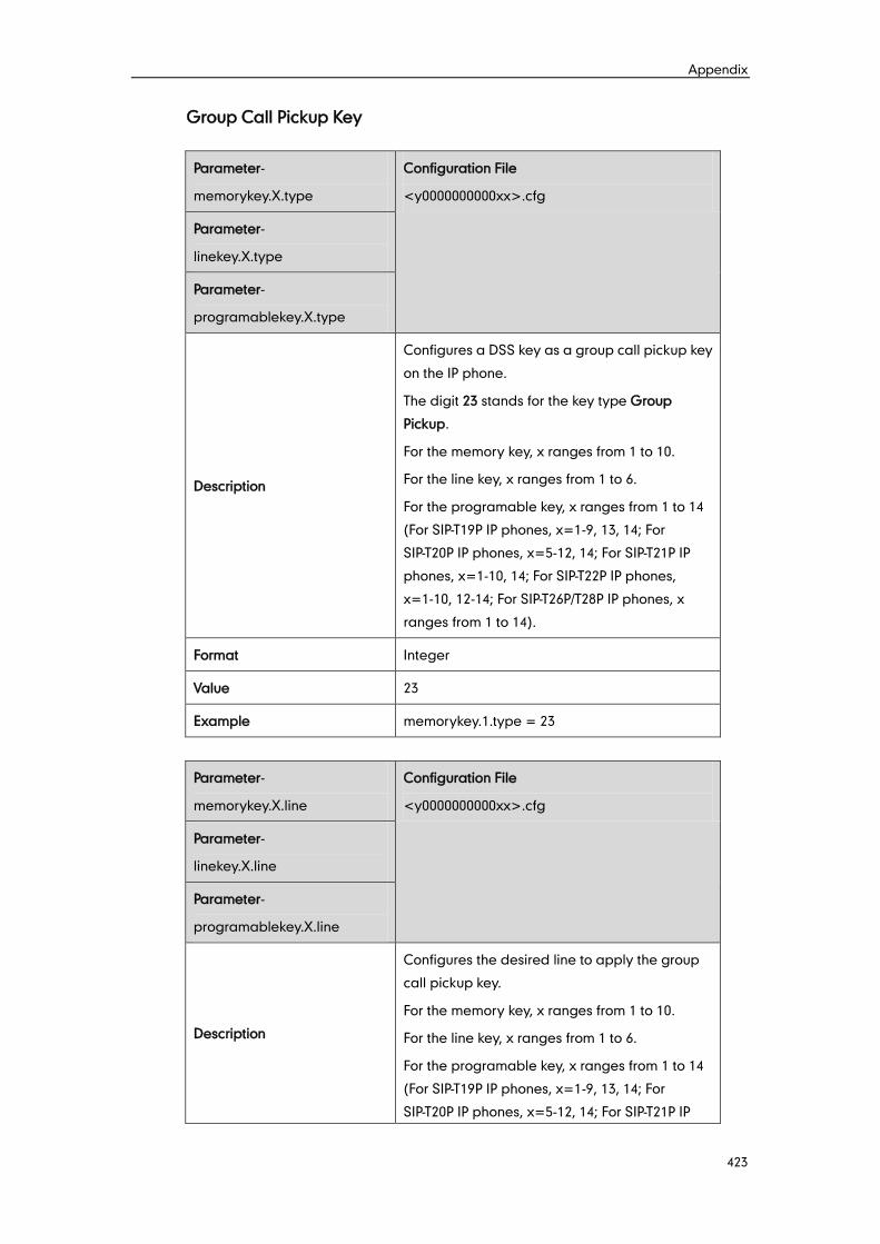
Appendix
423
Group Call Pickup Key
Parameter-
memorykey.X.type
Configuration File
<y0000000000xx>.cfg
Parameter-
linekey.X.type
Parameter-
programablekey.X.type
Description
Configures a DSS key as a group call pickup key
on the IP phone.
The digit 23 stands for the key type Group
Pickup.
For the memory key, x ranges from 1 to 10.
For the line key, x ranges from 1 to 6.
For the programable key, x ranges from 1 to 14
(For SIP-T19P IP phones, x=1-9, 13, 14; For
SIP-T20P IP phones, x=5-12, 14; For SIP-T21P IP
phones, x=1-10, 14; For SIP-T22P IP phones,
x=1-10, 12-14; For SIP-T26P/T28P IP phones, x
ranges from 1 to 14).
Format Integer
Value 23
Example memorykey.1.type = 23
Parameter-
memorykey.X.line
Configuration File
<y0000000000xx>.cfg
Parameter-
linekey.X.line
Parameter-
programablekey.X.line
Description
Configures the desired line to apply the group
call pickup key.
For the memory key, x ranges from 1 to 10.
For the line key, x ranges from 1 to 6.
For the programable key, x ranges from 1 to 14
(For SIP-T19P IP phones, x=1-9, 13, 14; For
SIP-T20P IP phones, x=5-12, 14; For SIP-T21P IP
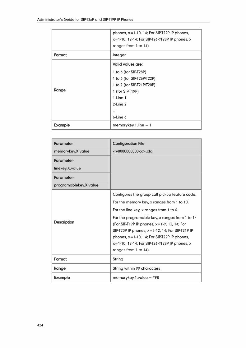
Administrator’s Guide for SIP-T2xP and SIP-T19P IP Phones
424
phones, x=1-10, 14; For SIP-T22P IP phones,
x=1-10, 12-14; For SIP-T26P/T28P IP phones, x
ranges from 1 to 14).
Format Integer
Range
Valid values are:
1 to 6 (for SIP-T28P)
1 to 3 (for SIP-T26P/T22P)
1 to 2 (for SIP-T21P/T20P)
1 (for SIP-T19P)
1-Line 1
2-Line 2
…
6-Line 6
Example memorykey.1.line = 1
Parameter-
memorykey.X.value
Configuration File
<y0000000000xx>.cfg
Parameter-
linekey.X.value
Parameter-
programablekey.X.value
Description
Configures the group call pickup feature code.
For the memory key, x ranges from 1 to 10.
For the line key, x ranges from 1 to 6.
For the programable key, x ranges from 1 to 14
(For SIP-T19P IP phones, x=1-9, 13, 14; For
SIP-T20P IP phones, x=5-12, 14; For SIP-T21P IP
phones, x=1-10, 14; For SIP-T22P IP phones,
x=1-10, 12-14; For SIP-T26P/T28P IP phones, x
ranges from 1 to 14).
Format String
Range String within 99 characters
Example memorykey.1.value = *98
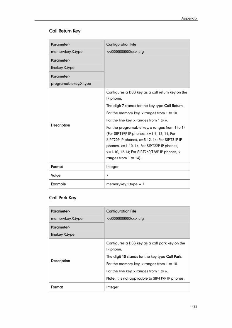
Appendix
425
Call Return Key
Parameter-
memorykey.X.type
Configuration File
<y0000000000xx>.cfg
Parameter-
linekey.X.type
Parameter-
programablekey.X.type
Description
Configures a DSS key as a call return key on the
IP phone.
The digit 7 stands for the key type Call Return.
For the memory key, x ranges from 1 to 10.
For the line key, x ranges from 1 to 6.
For the programable key, x ranges from 1 to 14
(For SIP-T19P IP phones, x=1-9, 13, 14; For
SIP-T20P IP phones, x=5-12, 14; For SIP-T21P IP
phones, x=1-10, 14; For SIP-T22P IP phones,
x=1-10, 12-14; For SIP-T26P/T28P IP phones, x
ranges from 1 to 14).
Format Integer
Value 7
Example memorykey.1.type = 7
Call Park Key
Parameter-
memorykey.X.type
Configuration File
<y0000000000xx>.cfg
Parameter-
linekey.X.type
Description
Configures a DSS key as a call park key on the
IP phone.
The digit 10 stands for the key type Call Park.
For the memory key, x ranges from 1 to 10.
For the line key, x ranges from 1 to 6.
Note: It is not applicable to SIP-T19P IP phones.
Format Integer
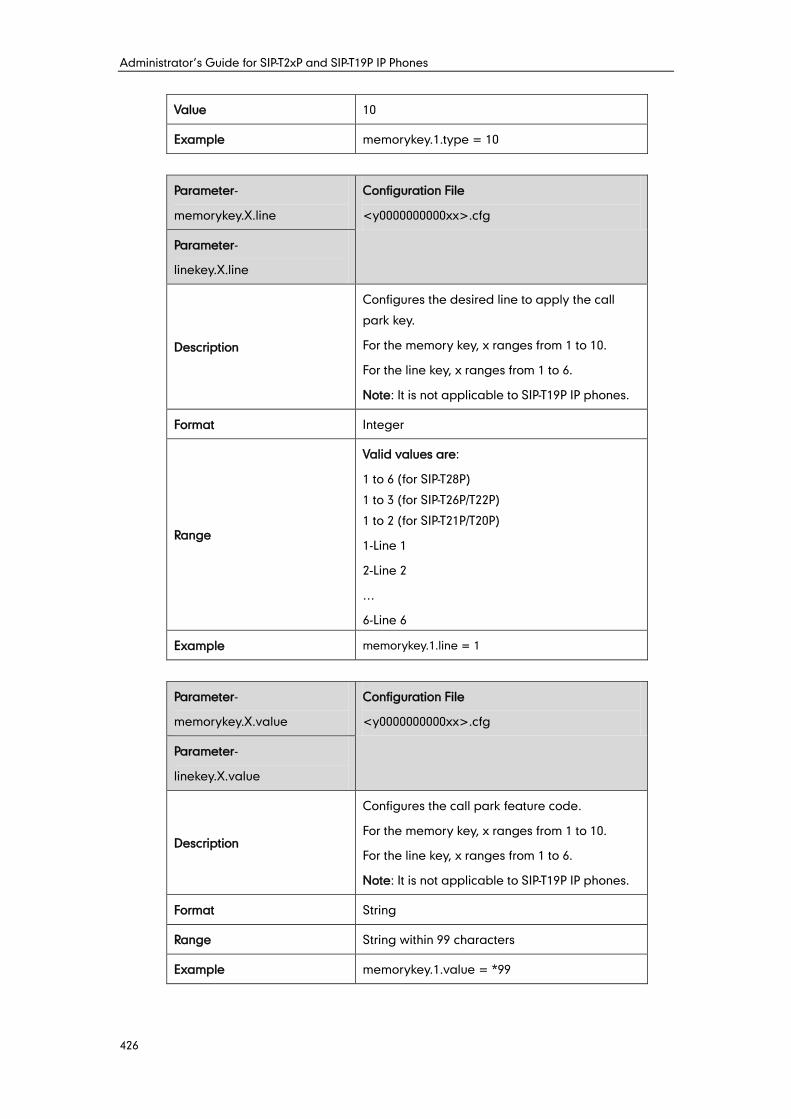
Administrator’s Guide for SIP-T2xP and SIP-T19P IP Phones
426
Value 10
Example memorykey.1.type = 10
Parameter-
memorykey.X.line
Configuration File
<y0000000000xx>.cfg
Parameter-
linekey.X.line
Description
Configures the desired line to apply the call
park key.
For the memory key, x ranges from 1 to 10.
For the line key, x ranges from 1 to 6.
Note: It is not applicable to SIP-T19P IP phones.
Format Integer
Range
Valid values are:
1 to 6 (for SIP-T28P)
1 to 3 (for SIP-T26P/T22P)
1 to 2 (for SIP-T21P/T20P)
1-Line 1
2-Line 2
…
6-Line 6
Example memorykey.1.line = 1
Parameter-
memorykey.X.value
Configuration File
<y0000000000xx>.cfg
Parameter-
linekey.X.value
Description
Configures the call park feature code.
For the memory key, x ranges from 1 to 10.
For the line key, x ranges from 1 to 6.
Note: It is not applicable to SIP-T19P IP phones.
Format String
Range String within 99 characters
Example memorykey.1.value = *99
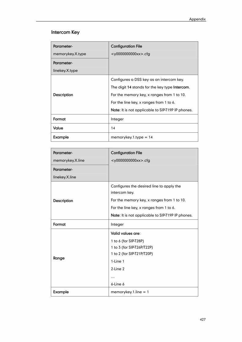
Appendix
427
Intercom Key
Parameter-
memorykey.X.type
Configuration File
<y0000000000xx>.cfg
Parameter-
linekey.X.type
Description
Configures a DSS key as an intercom key.
The digit 14 stands for the key type Intercom.
For the memory key, x ranges from 1 to 10.
For the line key, x ranges from 1 to 6.
Note: It is not applicable to SIP-T19P IP phones.
Format Integer
Value 14
Example memorykey.1.type = 14
Parameter-
memorykey.X.line
Configuration File
<y0000000000xx>.cfg
Parameter-
linekey.X.line
Description
Configures the desired line to apply the
intercom key.
For the memory key, x ranges from 1 to 10.
For the line key, x ranges from 1 to 6.
Note: It is not applicable to SIP-T19P IP phones.
Format Integer
Range
Valid values are:
1 to 6 (for SIP-T28P)
1 to 3 (for SIP-T26P/T22P)
1 to 2 (for SIP-T21P/T20P)
1-Line 1
2-Line 2
…
6-Line 6
Example memorykey.1.line = 1
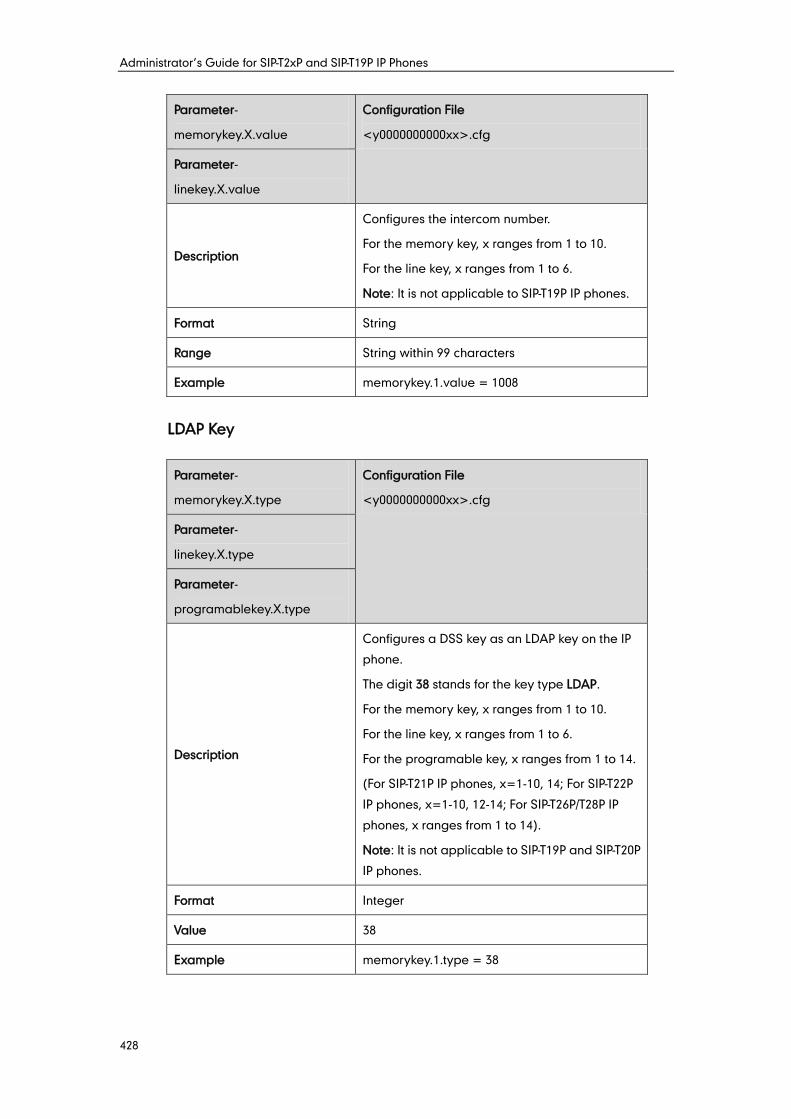
Administrator’s Guide for SIP-T2xP and SIP-T19P IP Phones
428
Parameter-
memorykey.X.value
Configuration File
<y0000000000xx>.cfg
Parameter-
linekey.X.value
Description
Configures the intercom number.
For the memory key, x ranges from 1 to 10.
For the line key, x ranges from 1 to 6.
Note: It is not applicable to SIP-T19P IP phones.
Format String
Range String within 99 characters
Example memorykey.1.value = 1008
LDAP Key
Parameter-
memorykey.X.type
Configuration File
<y0000000000xx>.cfg
Parameter-
linekey.X.type
Parameter-
programablekey.X.type
Description
Configures a DSS key as an LDAP key on the IP
phone.
The digit 38 stands for the key type LDAP.
For the memory key, x ranges from 1 to 10.
For the line key, x ranges from 1 to 6.
For the programable key, x ranges from 1 to 14.
(For SIP-T21P IP phones, x=1-10, 14; For SIP-T22P
IP phones, x=1-10, 12-14; For SIP-T26P/T28P IP
phones, x ranges from 1 to 14).
Note: It is not applicable to SIP-T19P and SIP-T20P
IP phones.
Format Integer
Value 38
Example memorykey.1.type = 38
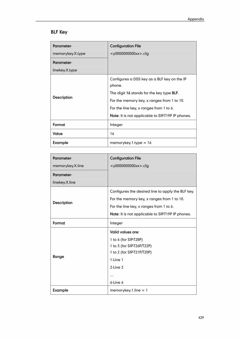
Appendix
429
BLF Key
Parameter-
memorykey.X.type
Configuration File
<y0000000000xx>.cfg
Parameter-
linekey.X.type
Description
Configures a DSS key as a BLF key on the IP
phone.
The digit 16 stands for the key type BLF.
For the memory key, x ranges from 1 to 10.
For the line key, x ranges from 1 to 6.
Note: It is not applicable to SIP-T19P IP phones.
Format Integer
Value 16
Example memorykey.1.type = 16
Parameter-
memorykey.X.line
Configuration File
<y0000000000xx>.cfg
Parameter-
linekey.X.line
Description
Configures the desired line to apply the BLF key.
For the memory key, x ranges from 1 to 10.
For the line key, x ranges from 1 to 6.
Note: It is not applicable to SIP-T19P IP phones.
Format Integer
Range
Valid values are:
1 to 6 (for SIP-T28P)
1 to 3 (for SIP-T26P/T22P)
1 to 2 (for SIP-T21P/T20P)
1-Line 1
2-Line 2
…
6-Line 6
Example memorykey.1.line = 1
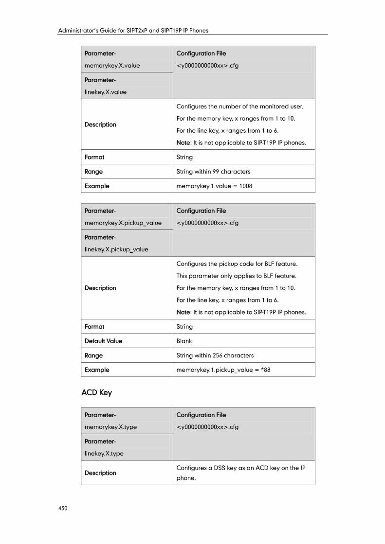
Administrator’s Guide for SIP-T2xP and SIP-T19P IP Phones
430
Parameter-
memorykey.X.value
Configuration File
<y0000000000xx>.cfg
Parameter-
linekey.X.value
Description
Configures the number of the monitored user.
For the memory key, x ranges from 1 to 10.
For the line key, x ranges from 1 to 6.
Note: It is not applicable to SIP-T19P IP phones.
Format String
Range String within 99 characters
Example memorykey.1.value = 1008
Parameter-
memorykey.X.pickup_value
Configuration File
<y0000000000xx>.cfg
Parameter-
linekey.X.pickup_value
Description
Configures the pickup code for BLF feature.
This parameter only applies to BLF feature.
For the memory key, x ranges from 1 to 10.
For the line key, x ranges from 1 to 6.
Note: It is not applicable to SIP-T19P IP phones.
Format String
Default Value Blank
Range String within 256 characters
Example memorykey.1.pickup_value = *88
ACD Key
Parameter-
memorykey.X.type
Configuration File
<y0000000000xx>.cfg
Parameter-
linekey.X.type
Description Configures a DSS key as an ACD key on the IP
phone.
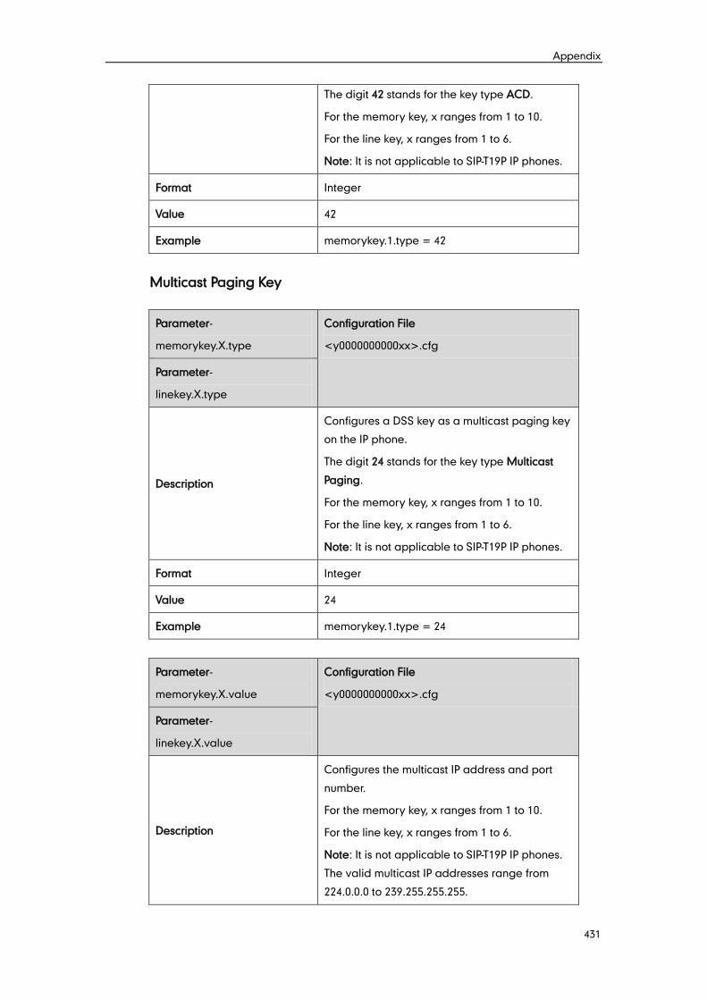
Appendix
431
The digit 42 stands for the key type ACD.
For the memory key, x ranges from 1 to 10.
For the line key, x ranges from 1 to 6.
Note: It is not applicable to SIP-T19P IP phones.
Format Integer
Value 42
Example memorykey.1.type = 42
Multicast Paging Key
Parameter-
memorykey.X.type
Configuration File
<y0000000000xx>.cfg
Parameter-
linekey.X.type
Description
Configures a DSS key as a multicast paging key
on the IP phone.
The digit 24 stands for the key type Multicast
Paging.
For the memory key, x ranges from 1 to 10.
For the line key, x ranges from 1 to 6.
Note: It is not applicable to SIP-T19P IP phones.
Format Integer
Value 24
Example memorykey.1.type = 24
Parameter-
memorykey.X.value
Configuration File
<y0000000000xx>.cfg
Parameter-
linekey.X.value
Description
Configures the multicast IP address and port
number.
For the memory key, x ranges from 1 to 10.
For the line key, x ranges from 1 to 6.
Note: It is not applicable to SIP-T19P IP phones.
The valid multicast IP addresses range from
224.0.0.0 to 239.255.255.255.
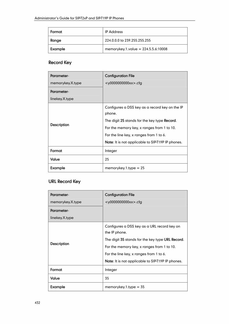
Administrator’s Guide for SIP-T2xP and SIP-T19P IP Phones
432
Format IP Address
Range 224.0.0.0 to 239.255.255.255
Example memorykey.1.value = 224.5.5.6:10008
Record Key
Parameter-
memorykey.X.type
Configuration File
<y0000000000xx>.cfg
Parameter-
linekey.X.type
Description
Configures a DSS key as a record key on the IP
phone.
The digit 25 stands for the key type Record.
For the memory key, x ranges from 1 to 10.
For the line key, x ranges from 1 to 6.
Note: It is not applicable to SIP-T19P IP phones.
Format Integer
Value 25
Example memorykey.1.type = 25
URL Record Key
Parameter-
memorykey.X.type
Configuration File
<y0000000000xx>.cfg
Parameter-
linekey.X.type
Description
Configures a DSS key as a URL record key on
the IP phone.
The digit 35 stands for the key type URL Record.
For the memory key, x ranges from 1 to 10.
For the line key, x ranges from 1 to 6.
Note: It is not applicable to SIP-T19P IP phones.
Format Integer
Value 35
Example memorykey.1.type = 35
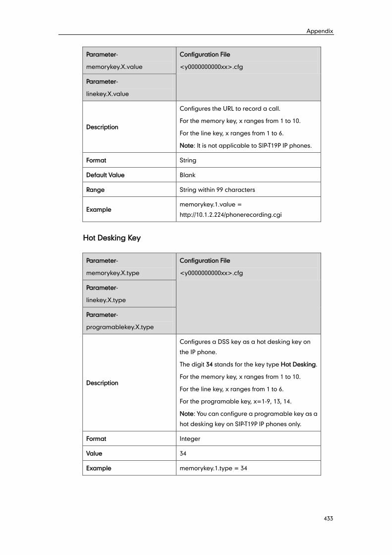
Appendix
433
Parameter-
memorykey.X.value
Configuration File
<y0000000000xx>.cfg
Parameter-
linekey.X.value
Description
Configures the URL to record a call.
For the memory key, x ranges from 1 to 10.
For the line key, x ranges from 1 to 6.
Note: It is not applicable to SIP-T19P IP phones.
Format String
Default Value Blank
Range String within 99 characters
Example memorykey.1.value =
http://10.1.2.224/phonerecording.cgi
Hot Desking Key
Parameter-
memorykey.X.type
Configuration File
<y0000000000xx>.cfg
Parameter-
linekey.X.type
Parameter-
programablekey.X.type
Description
Configures a DSS key as a hot desking key on
the IP phone.
The digit 34 stands for the key type Hot Desking.
For the memory key, x ranges from 1 to 10.
For the line key, x ranges from 1 to 6.
For the programable key, x=1-9, 13, 14.
Note: You can configure a programable key as a
hot desking key on SIP-T19P IP phones only.
Format Integer
Value 34
Example memorykey.1.type = 34
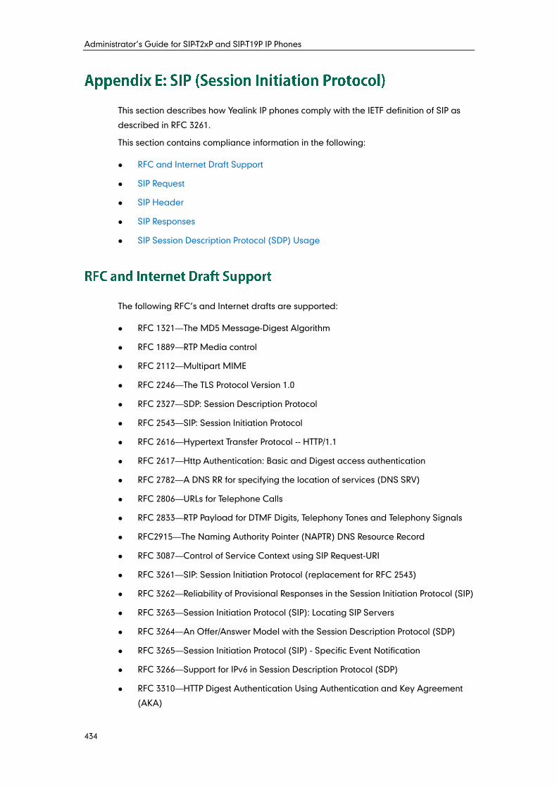
Administrator’s Guide for SIP-T2xP and SIP-T19P IP Phones
434
This section describes how Yealink IP phones comply with the IETF definition of SIP as
described in RFC 3261.
This section contains compliance information in the following:
RFC and Internet Draft Support
SIP Request
SIP Header
SIP Responses
SIP Session Description Protocol (SDP) Usage
The following RFC’s and Internet drafts are supported:
RFC 1321—The MD5 Message-Digest Algorithm
RFC 1889—RTP Media control
RFC 2112—Multipart MIME
RFC 2246—The TLS Protocol Version 1.0
RFC 2327—SDP: Session Description Protocol
RFC 2543—SIP: Session Initiation Protocol
RFC 2616—Hypertext Transfer Protocol -- HTTP/1.1
RFC 2617—Http Authentication: Basic and Digest access authentication
RFC 2782—A DNS RR for specifying the location of services (DNS SRV)
RFC 2806—URLs for Telephone Calls
RFC 2833—RTP Payload for DTMF Digits, Telephony Tones and Telephony Signals
RFC2915—The Naming Authority Pointer (NAPTR) DNS Resource Record
RFC 3087—Control of Service Context using SIP Request-URI
RFC 3261—SIP: Session Initiation Protocol (replacement for RFC 2543)
RFC 3262—Reliability of Provisional Responses in the Session Initiation Protocol (SIP)
RFC 3263—Session Initiation Protocol (SIP): Locating SIP Servers
RFC 3264—An Offer/Answer Model with the Session Description Protocol (SDP)
RFC 3265—Session Initiation Protocol (SIP) - Specific Event Notification
RFC 3266—Support for IPv6 in Session Description Protocol (SDP)
RFC 3310—HTTP Digest Authentication Using Authentication and Key Agreement
(AKA)
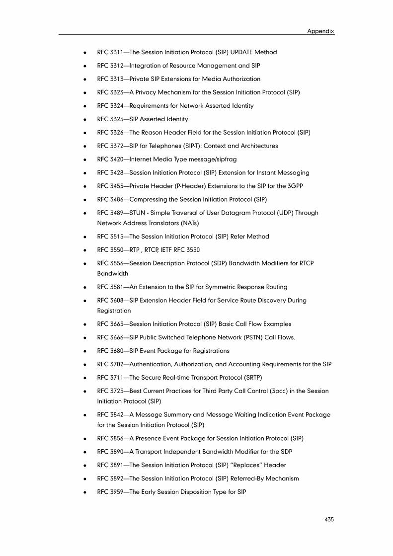
Appendix
435
RFC 3311—The Session Initiation Protocol (SIP) UPDATE Method
RFC 3312—Integration of Resource Management and SIP
RFC 3313—Private SIP Extensions for Media Authorization
RFC 3323—A Privacy Mechanism for the Session Initiation Protocol (SIP)
RFC 3324—Requirements for Network Asserted Identity
RFC 3325—SIP Asserted Identity
RFC 3326—The Reason Header Field for the Session Initiation Protocol (SIP)
RFC 3372—SIP for Telephones (SIP-T): Context and Architectures
RFC 3420—Internet Media Type message/sipfrag
RFC 3428—Session Initiation Protocol (SIP) Extension for Instant Messaging
RFC 3455—Private Header (P-Header) Extensions to the SIP for the 3GPP
RFC 3486—Compressing the Session Initiation Protocol (SIP)
RFC 3489—STUN - Simple Traversal of User Datagram Protocol (UDP) Through
Network Address Translators (NATs)
RFC 3515—The Session Initiation Protocol (SIP) Refer Method
RFC 3550—RTP , RTCP, IETF RFC 3550
RFC 3556—Session Description Protocol (SDP) Bandwidth Modifiers for RTCP
Bandwidth
RFC 3581—An Extension to the SIP for Symmetric Response Routing
RFC 3608—SIP Extension Header Field for Service Route Discovery During
Registration
RFC 3665—Session Initiation Protocol (SIP) Basic Call Flow Examples
RFC 3666—SIP Public Switched Telephone Network (PSTN) Call Flows.
RFC 3680—SIP Event Package for Registrations
RFC 3702—Authentication, Authorization, and Accounting Requirements for the SIP
RFC 3711—The Secure Real-time Transport Protocol (SRTP)
RFC 3725—Best Current Practices for Third Party Call Control (3pcc) in the Session
Initiation Protocol (SIP)
RFC 3842—A Message Summary and Message Waiting Indication Event Package
for the Session Initiation Protocol (SIP)
RFC 3856—A Presence Event Package for Session Initiation Protocol (SIP)
RFC 3890—A Transport Independent Bandwidth Modifier for the SDP
RFC 3891—The Session Initiation Protocol (SIP) “Replaces” Header
RFC 3892—The Session Initiation Protocol (SIP) Referred-By Mechanism
RFC 3959—The Early Session Disposition Type for SIP
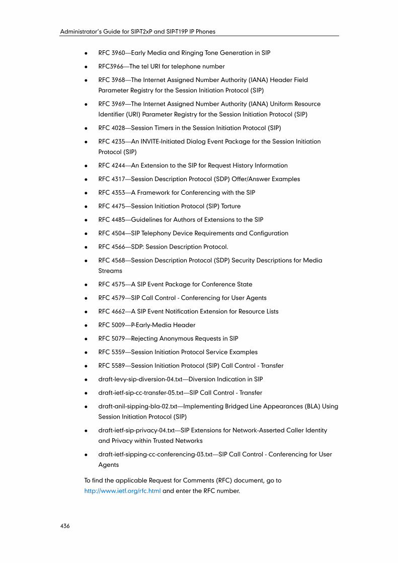
Administrator’s Guide for SIP-T2xP and SIP-T19P IP Phones
436
RFC 3960—Early Media and Ringing Tone Generation in SIP
RFC3966—The tel URI for telephone number
RFC 3968—The Internet Assigned Number Authority (IANA) Header Field
Parameter Registry for the Session Initiation Protocol (SIP)
RFC 3969—The Internet Assigned Number Authority (IANA) Uniform Resource
Identifier (URI) Parameter Registry for the Session Initiation Protocol (SIP)
RFC 4028—Session Timers in the Session Initiation Protocol (SIP)
RFC 4235—An INVITE-Initiated Dialog Event Package for the Session Initiation
Protocol (SIP)
RFC 4244—An Extension to the SIP for Request History Information
RFC 4317—Session Description Protocol (SDP) Offer/Answer Examples
RFC 4353—A Framework for Conferencing with the SIP
RFC 4475—Session Initiation Protocol (SIP) Torture
RFC 4485—Guidelines for Authors of Extensions to the SIP
RFC 4504—SIP Telephony Device Requirements and Configuration
RFC 4566—SDP: Session Description Protocol.
RFC 4568—Session Description Protocol (SDP) Security Descriptions for Media
Streams
RFC 4575—A SIP Event Package for Conference State
RFC 4579—SIP Call Control - Conferencing for User Agents
RFC 4662—A SIP Event Notification Extension for Resource Lists
RFC 5009—P-Early-Media Header
RFC 5079—Rejecting Anonymous Requests in SIP
RFC 5359—Session Initiation Protocol Service Examples
RFC 5589—Session Initiation Protocol (SIP) Call Control - Transfer
draft-levy-sip-diversion-04.txt—Diversion Indication in SIP
draft-ietf-sip-cc-transfer-05.txt—SIP Call Control - Transfer
draft-anil-sipping-bla-02.txt—Implementing Bridged Line Appearances (BLA) Using
Session Initiation Protocol (SIP)
draft-ietf-sip-privacy-04.txt—SIP Extensions for Network-Asserted Caller Identity
and Privacy within Trusted Networks
draft-ietf-sipping-cc-conferencing-03.txt—SIP Call Control - Conferencing for User
Agents
To find the applicable Request for Comments (RFC) document, go to
http://www.ietf.org/rfc.html and enter the RFC number.
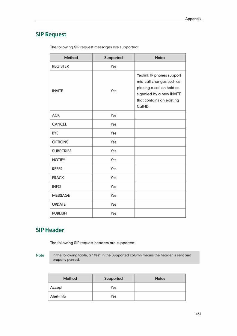
Appendix
437
The following SIP request messages are supported:
Method Supported Notes
REGISTER Yes
INVITE Yes
Yealink IP phones support
mid-call changes such as
placing a call on hold as
signaled by a new INVITE
that contains an existing
Call-ID.
ACK Yes
CANCEL Yes
BYE Yes
OPTIONS Yes
SUBSCRIBE Yes
NOTIFY Yes
REFER Yes
PRACK Yes
INFO Yes
MESSAGE Yes
UPDATE Yes
PUBLISH Yes
The following SIP request headers are supported:
Note
Method Supported Notes
Accept Yes
Alert-Info Yes
In the following table, a “Yes” in the Supported column means the header is sent and
properly parsed.
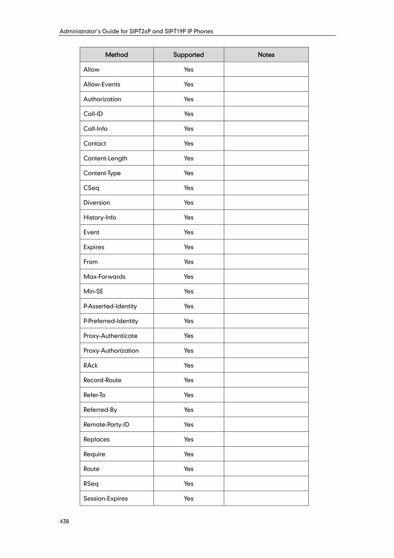
Administrator’s Guide for SIP-T2xP and SIP-T19P IP Phones
438
Method Supported Notes
Allow Yes
Allow-Events Yes
Authorization Yes
Call-ID Yes
Call-Info Yes
Contact Yes
Content-Length Yes
Content-Type Yes
CSeq Yes
Diversion Yes
History-Info Yes
Event Yes
Expires Yes
From Yes
Max-Forwards Yes
Min-SE Yes
P-Asserted-Identity Yes
P-Preferred-Identity Yes
Proxy-Authenticate Yes
Proxy-Authorization Yes
RAck Yes
Record-Route Yes
Refer-To Yes
Referred-By Yes
Remote-Party-ID Yes
Replaces Yes
Require Yes
Route Yes
RSeq Yes
Session-Expires Yes
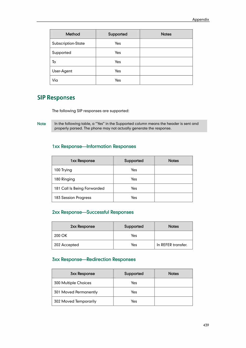
Appendix
439
Method Supported Notes
Subscription-State Yes
Supported Yes
To Yes
User-Agent Yes
Via Yes
The following SIP responses are supported:
Note
1xx Response—Information Responses
1xx Response Supported Notes
100 Trying Yes
180 Ringing Yes
181 Call Is Being Forwarded Yes
183 Session Progress Yes
2xx Response—Successful Responses
2xx Response Supported Notes
200 OK Yes
202 Accepted Yes In REFER transfer.
3xx Response—Redirection Responses
3xx Response Supported Notes
300 Multiple Choices Yes
301 Moved Permanently Yes
302 Moved Temporarily Yes
In the following table, a “Yes” in the Supported column means the header is sent and
properly parsed. The phone may not actually generate the response.
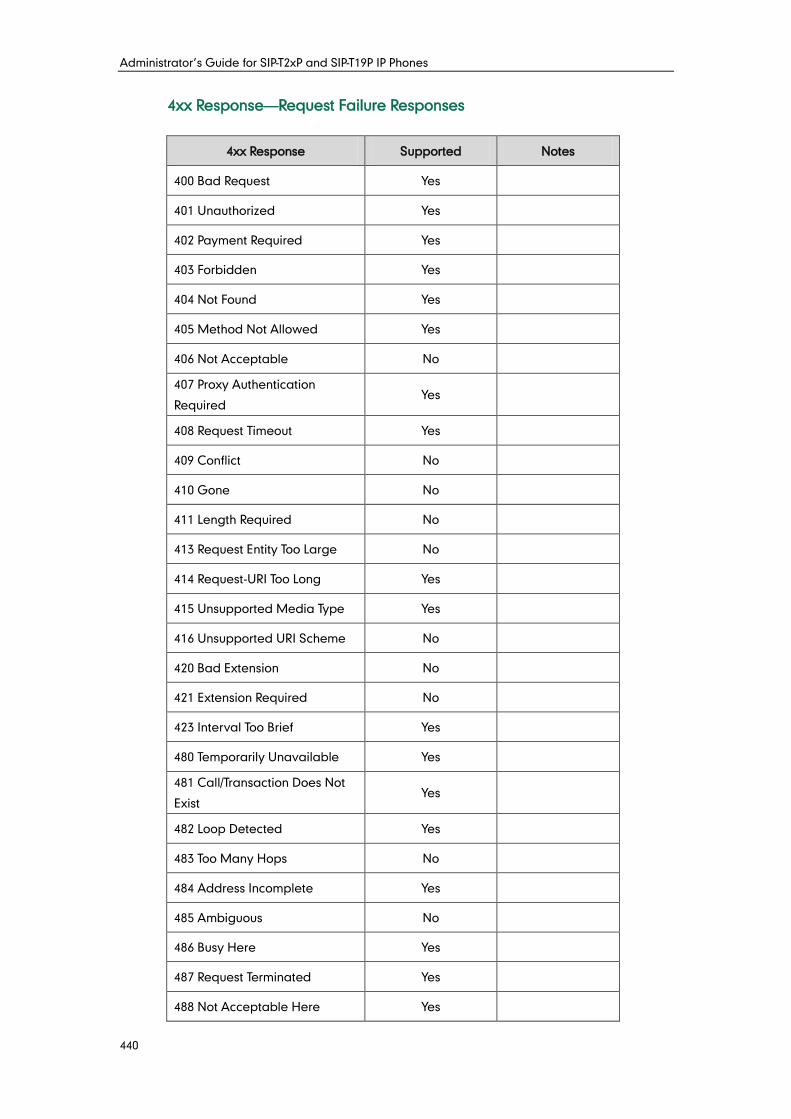
Administrator’s Guide for SIP-T2xP and SIP-T19P IP Phones
440
4xx Response—Request Failure Responses
4xx Response Supported Notes
400 Bad Request Yes
401 Unauthorized Yes
402 Payment Required Yes
403 Forbidden Yes
404 Not Found Yes
405 Method Not Allowed Yes
406 Not Acceptable No
407 Proxy Authentication
Required Yes
408 Request Timeout Yes
409 Conflict No
410 Gone No
411 Length Required No
413 Request Entity Too Large No
414 Request-URI Too Long Yes
415 Unsupported Media Type Yes
416 Unsupported URI Scheme No
420 Bad Extension No
421 Extension Required No
423 Interval Too Brief Yes
480 Temporarily Unavailable Yes
481 Call/Transaction Does Not
Exist Yes
482 Loop Detected Yes
483 Too Many Hops No
484 Address Incomplete Yes
485 Ambiguous No
486 Busy Here Yes
487 Request Terminated Yes
488 Not Acceptable Here Yes
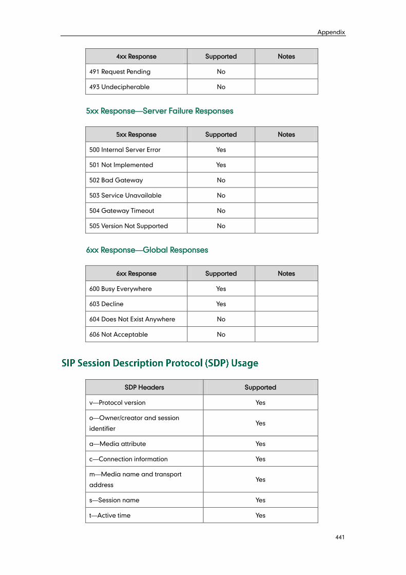
Appendix
441
4xx Response Supported Notes
491 Request Pending No
493 Undecipherable No
5xx Response—Server Failure Responses
5xx Response Supported Notes
500 Internal Server Error Yes
501 Not Implemented Yes
502 Bad Gateway No
503 Service Unavailable No
504 Gateway Timeout No
505 Version Not Supported No
6xx Response—Global Responses
6xx Response Supported Notes
600 Busy Everywhere Yes
603 Decline Yes
604 Does Not Exist Anywhere No
606 Not Acceptable No
SDP Headers Supported
v—Protocol version Yes
o—Owner/creator and session
identifier Yes
a—Media attribute Yes
c—Connection information Yes
m—Media name and transport
address Yes
s—Session name Yes
t—Active time Yes
Administrator’s Guide for SIP-T2xP and SIP-T19P IP Phones
442
SIP uses six request methods:
INVITE—Indicates a user is being invited to participate in a call session.
ACK—Confirms that the client has received a final response to an INVITE request.
BYE—Terminates a call and can be sent by either the caller or the callee.
CANCEL—Cancels any pending searches but does not terminate a call that has
already been accepted.
OPTIONS—Queries the capabilities of servers.
REGISTER—Registers the address listed in the To header field with a SIP server.
The following types of responses are used by SIP and generated by the IP phone or the
SIP server:
SIP 1xx—Informational Responses
SIP 2xx—Successful Responses
SIP 3xx—Redirection Responses
SIP 4xx—Client Failure Responses
SIP 5xx—Server Failure Responses
SIP 6xx—Global Failure Responses
The following figure illustrates the scenario of a successful call. In this scenario, the two
end users are User A and User B. User A and User B are located at Yealink SIP IP
phones.
The call flow scenario is as follows:
1. User A calls User B.
2. User B answers the call.
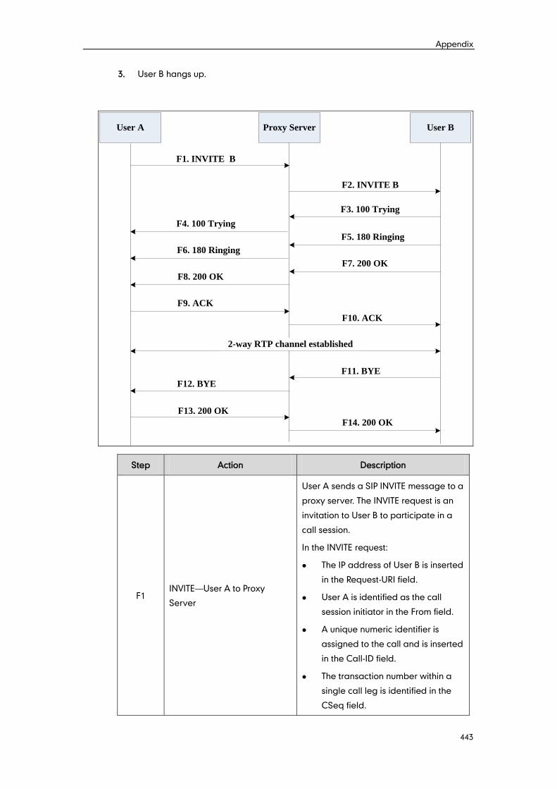
Appendix
443
3. User B hangs up.
User A Proxy Server User B
F1. INVITE B
F2. INVITE B
F3. 100 Trying
F9. ACK
F10. ACK
F5. 180 Ringing
2-way RTP channel established
F8. 200 OK
F7. 200 OK
F6. 180 Ringing
F4. 100 Trying
F11. BYE
F12. BYE
F13. 200 OK
F14. 200 OK
Step Action Description
F1 INVITE—User A to Proxy
Server
User A sends a SIP INVITE message to a
proxy server. The INVITE request is an
invitation to User B to participate in a
call session.
In the INVITE request:
The IP address of User B is inserted
in the Request-URI field.
User A is identified as the call
session initiator in the From field.
A unique numeric identifier is
assigned to the call and is inserted
in the Call-ID field.
The transaction number within a
single call leg is identified in the
CSeq field.
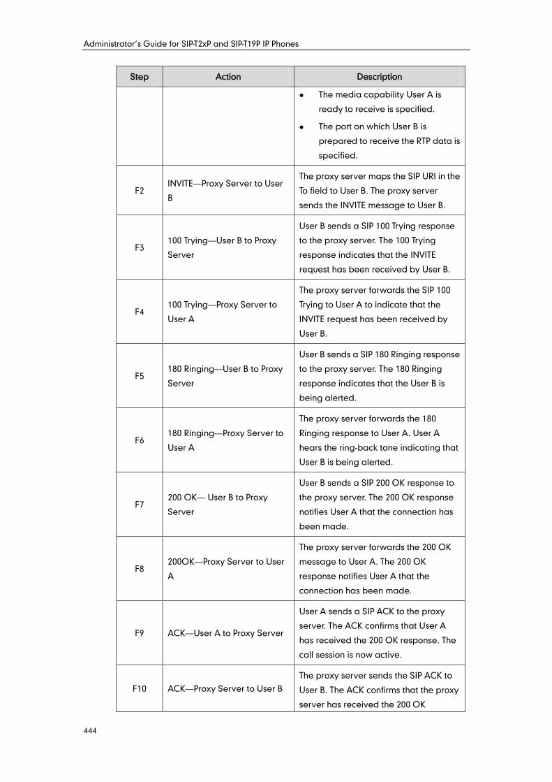
Administrator’s Guide for SIP-T2xP and SIP-T19P IP Phones
444
Step Action Description
The media capability User A is
ready to receive is specified.
The port on which User B is
prepared to receive the RTP data is
specified.
F2 INVITE—Proxy Server to User
B
The proxy server maps the SIP URI in the
To field to User B. The proxy server
sends the INVITE message to User B.
F3 100 Trying—User B to Proxy
Server
User B sends a SIP 100 Trying response
to the proxy server. The 100 Trying
response indicates that the INVITE
request has been received by User B.
F4 100 Trying—Proxy Server to
User A
The proxy server forwards the SIP 100
Trying to User A to indicate that the
INVITE request has been received by
User B.
F5 180 Ringing—User B to Proxy
Server
User B sends a SIP 180 Ringing response
to the proxy server. The 180 Ringing
response indicates that the User B is
being alerted.
F6 180 Ringing—Proxy Server to
User A
The proxy server forwards the 180
Ringing response to User A. User A
hears the ring-back tone indicating that
User B is being alerted.
F7 200 OK— User B to Proxy
Server
User B sends a SIP 200 OK response to
the proxy server. The 200 OK response
notifies User A that the connection has
been made.
F8 200OK—Proxy Server to User
A
The proxy server forwards the 200 OK
message to User A. The 200 OK
response notifies User A that the
connection has been made.
F9 ACK—User A to Proxy Server
User A sends a SIP ACK to the proxy
server. The ACK confirms that User A
has received the 200 OK response. The
call session is now active.
F10 ACK—Proxy Server to User B
The proxy server sends the SIP ACK to
User B. The ACK confirms that the proxy
server has received the 200 OK
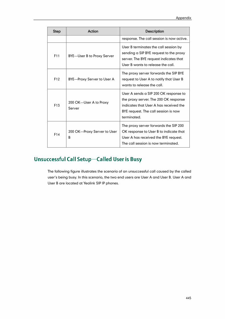
Appendix
445
Step Action Description
response. The call session is now active.
F11 BYE—User B to Proxy Server
User B terminates the call session by
sending a SIP BYE request to the proxy
server. The BYE request indicates that
User B wants to release the call.
F12 BYE—Proxy Server to User A
The proxy server forwards the SIP BYE
request to User A to notify that User B
wants to release the call.
F13 200 OK—User A to Proxy
Server
User A sends a SIP 200 OK response to
the proxy server. The 200 OK response
indicates that User A has received the
BYE request. The call session is now
terminated.
F14 200 OK—Proxy Server to User
B
The proxy server forwards the SIP 200
OK response to User B to indicate that
User A has received the BYE request.
The call session is now terminated.
The following figure illustrates the scenario of an unsuccessful call caused by the called
user’s being busy. In this scenario, the two end users are User A and User B. User A and
User B are located at Yealink SIP IP phones.
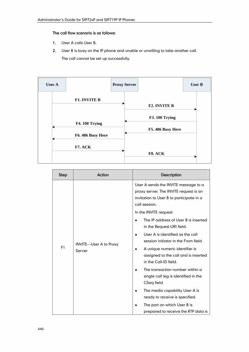
Administrator’s Guide for SIP-T2xP and SIP-T19P IP Phones
446
The call flow scenario is as follows:
1. User A calls User B.
2. User B is busy on the IP phone and unable or unwilling to take another call.
The call cannot be set up successfully.
User A Proxy Server User B
F1. INVITE B
F2. INVITE B
F3. 100 Trying
F4. 100 Trying
F5. 486 Busy Here
F6. 486 Busy Here
F7. ACK
F8. ACK
Step Action Description
F1 INVITE—User A to Proxy
Server
User A sends the INVITE message to a
proxy server. The INVITE request is an
invitation to User B to participate in a
call session.
In the INVITE request:
The IP address of User B is inserted
in the Request-URI field.
User A is identified as the call
session initiator in the From field.
A unique numeric identifier is
assigned to the call and is inserted
in the Call-ID field.
The transaction number within a
single call leg is identified in the
CSeq field.
The media capability User A is
ready to receive is specified.
The port on which User B is
prepared to receive the RTP data is
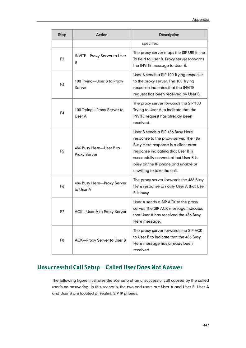
Appendix
447
Step Action Description
specified.
F2 INVITE—Proxy Server to User
B
The proxy server maps the SIP URI in the
To field to User B. Proxy server forwards
the INVITE message to User B.
F3 100 Trying—User B to Proxy
Server
User B sends a SIP 100 Trying response
to the proxy server. The 100 Trying
response indicates that the INVITE
request has been received by User B.
F4 100 Trying—Proxy Server to
User A
The proxy server forwards the SIP 100
Trying to User A to indicate that the
INVITE request has already been
received.
F5 486 Busy Here—User B to
Proxy Server
User B sends a SIP 486 Busy Here
response to the proxy server. The 486
Busy Here response is a client error
response indicating that User B is
successfully connected but User B is
busy on the IP phone and unable or
unwilling to take the call.
F6 486 Busy Here—Proxy Server
to User A
The proxy server forwards the 486 Busy
Here response to notify User A that User
B is busy.
F7 ACK—User A to Proxy Server
User A sends a SIP ACK to the proxy
server. The SIP ACK message indicates
that User A has received the 486 Busy
Here message.
F8 ACK—Proxy Server to User B
The proxy server forwards the SIP ACK
to User B to indicate that the 486 Busy
Here message has already been
received.
The following figure illustrates the scenario of an unsuccessful call caused by the called
user’s no answering. In this scenario, the two end users are User A and User B. User A
and User B are located at Yealink SIP IP phones.
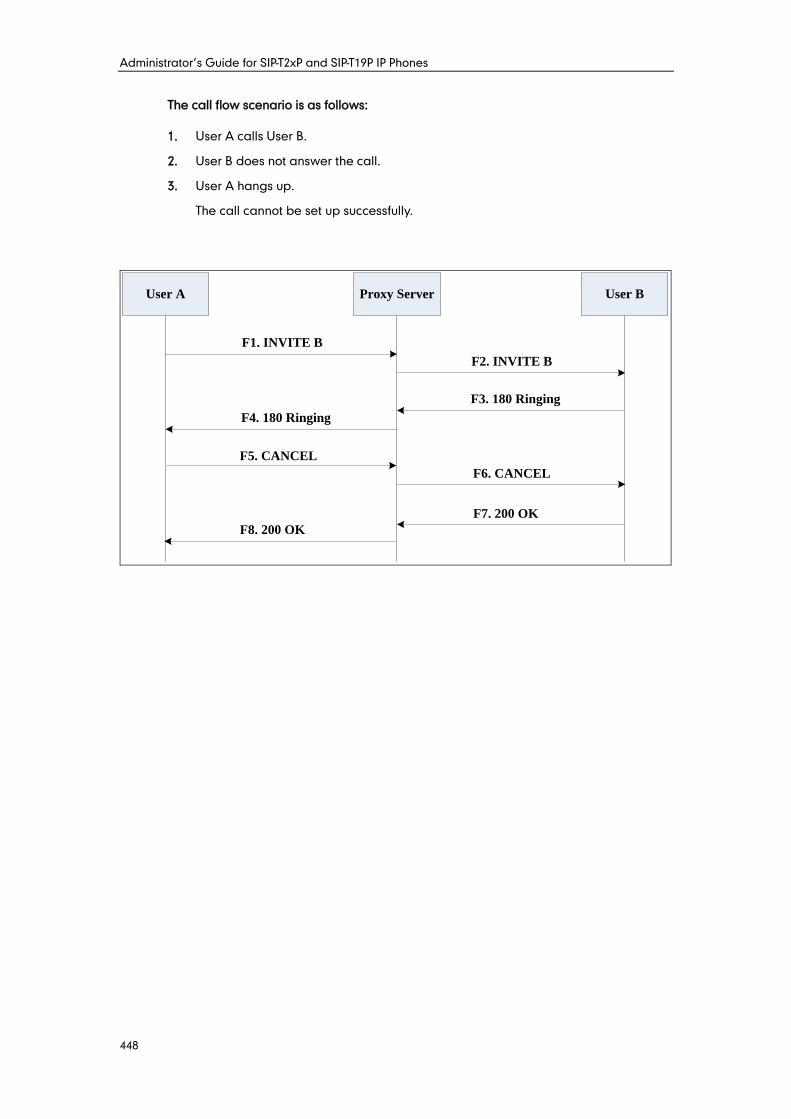
Administrator’s Guide for SIP-T2xP and SIP-T19P IP Phones
448
The call flow scenario is as follows:
1. User A calls User B.
2. User B does not answer the call.
3. User A hangs up.
The call cannot be set up successfully.
User A Proxy Server User B
F1. INVITE B
F2. INVITE B
F3. 180 Ringing
F4. 180 Ringing
F8. 200 OK
F7. 200 OK
F5. CANCEL
F6. CANCEL
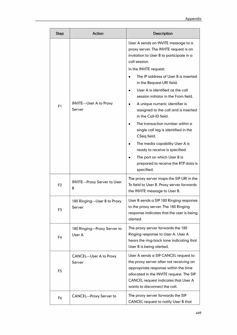
Appendix
449
Step Action Description
F1 INVITE—User A to Proxy
Server
User A sends an INVITE message to a
proxy server. The INVITE request is an
invitation to User B to participate in a
call session.
In the INVITE request:
The IP address of User B is inserted
in the Request-URI field.
User A is identified as the call
session initiator in the From field.
A unique numeric identifier is
assigned to the call and is inserted
in the Call-ID field.
The transaction number within a
single call leg is identified in the
CSeq field.
The media capability User A is
ready to receive is specified.
The port on which User B is
prepared to receive the RTP data is
specified.
F2 INVITE—Proxy Server to User
B
The proxy server maps the SIP URI in the
To field to User B. Proxy server forwards
the INVITE message to User B.
F3
180 Ringing—User B to Proxy
Server
User B sends a SIP 180 Ringing response
to the proxy server. The 180 Ringing
response indicates that the user is being
alerted.
F4
180 Ringing—Proxy Server to
User A
The proxy server forwards the 180
Ringing response to User A. User A
hears the ring-back tone indicating that
User B is being alerted.
F5
CANCEL—User A to Proxy
Server
User A sends a SIP CANCEL request to
the proxy server after not receiving an
appropriate response within the time
allocated in the INVITE request. The SIP
CANCEL request indicates that User A
wants to disconnect the call.
F6 CANCEL—Proxy Server to The proxy server forwards the SIP
CANCEL request to notify User B that
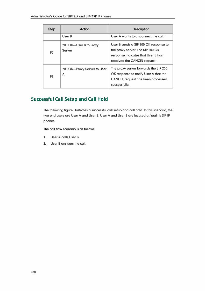
Administrator’s Guide for SIP-T2xP and SIP-T19P IP Phones
450
Step Action Description
User B User A wants to disconnect the call.
F7
200 OK—User B to Proxy
Server
User B sends a SIP 200 OK response to
the proxy server. The SIP 200 OK
response indicates that User B has
received the CANCEL request.
F8
200 OK—Proxy Server to User
A
The proxy server forwards the SIP 200
OK response to notify User A that the
CANCEL request has been processed
successfully.
The following figure illustrates a successful call setup and call hold. In this scenario, the
two end users are User A and User B. User A and User B are located at Yealink SIP IP
phones.
The call flow scenario is as follows:
1. User A calls User B.
2. User B answers the call.
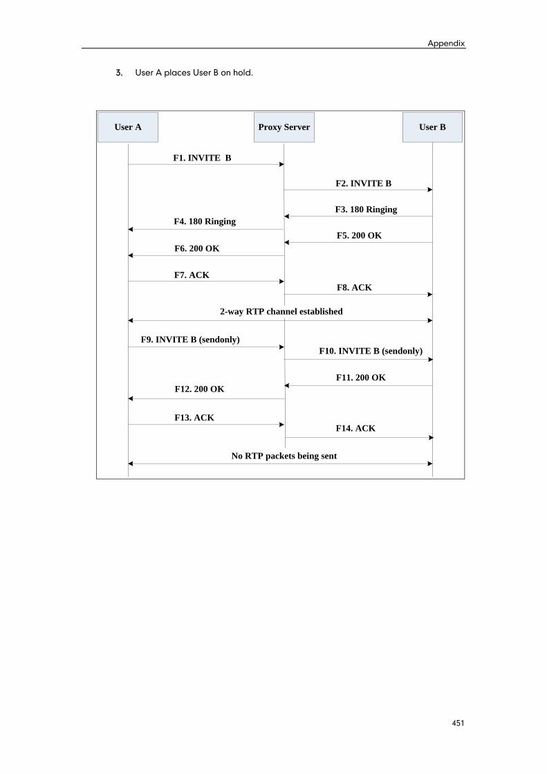
Appendix
451
3. User A places User B on hold.
User A Proxy Server User B
F1. INVITE B
F2. INVITE B
F7. ACK
F8. ACK
F3. 180 Ringing
F6. 200 OK
F5. 200 OK
F4. 180 Ringing
F12. 200 OK
F9. INVITE B (sendonly)
F10. INVITE B (sendonly)
F11. 200 OK
F14. ACK
F13. ACK
No RTP packets being sent
2-way RTP channel established
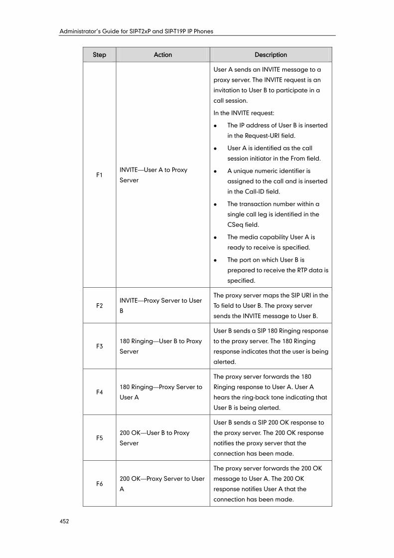
Administrator’s Guide for SIP-T2xP and SIP-T19P IP Phones
452
Step Action Description
F1 INVITE—User A to Proxy
Server
User A sends an INVITE message to a
proxy server. The INVITE request is an
invitation to User B to participate in a
call session.
In the INVITE request:
The IP address of User B is inserted
in the Request-URI field.
User A is identified as the call
session initiator in the From field.
A unique numeric identifier is
assigned to the call and is inserted
in the Call-ID field.
The transaction number within a
single call leg is identified in the
CSeq field.
The media capability User A is
ready to receive is specified.
The port on which User B is
prepared to receive the RTP data is
specified.
F2 INVITE—Proxy Server to User
B
The proxy server maps the SIP URI in the
To field to User B. The proxy server
sends the INVITE message to User B.
F3 180 Ringing—User B to Proxy
Server
User B sends a SIP 180 Ringing response
to the proxy server. The 180 Ringing
response indicates that the user is being
alerted.
F4 180 Ringing—Proxy Server to
User A
The proxy server forwards the 180
Ringing response to User A. User A
hears the ring-back tone indicating that
User B is being alerted.
F5 200 OK—User B to Proxy
Server
User B sends a SIP 200 OK response to
the proxy server. The 200 OK response
notifies the proxy server that the
connection has been made.
F6 200 OK—Proxy Server to User
A
The proxy server forwards the 200 OK
message to User A. The 200 OK
response notifies User A that the
connection has been made.
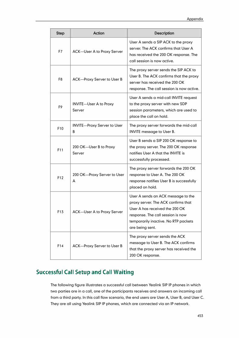
Appendix
453
Step Action Description
F7 ACK—User A to Proxy Server
User A sends a SIP ACK to the proxy
server. The ACK confirms that User A
has received the 200 OK response. The
call session is now active.
F8 ACK—Proxy Server to User B
The proxy server sends the SIP ACK to
User B. The ACK confirms that the proxy
server has received the 200 OK
response. The call session is now active.
F9 INVITE—User A to Proxy
Server
User A sends a mid-call INVITE request
to the proxy server with new SDP
session parameters, which are used to
place the call on hold.
F10 INVITE—Proxy Server to User
B
The proxy server forwards the mid-call
INVITE message to User B.
F11 200 OK—User B to Proxy
Server
User B sends a SIP 200 OK response to
the proxy server. The 200 OK response
notifies User A that the INVITE is
successfully processed.
F12 200 OK—Proxy Server to User
A
The proxy server forwards the 200 OK
response to User A. The 200 OK
response notifies User B is successfully
placed on hold.
F13 ACK—User A to Proxy Server
User A sends an ACK message to the
proxy server. The ACK confirms that
User A has received the 200 OK
response. The call session is now
temporarily inactive. No RTP packets
are being sent.
F14 ACK—Proxy Server to User B
The proxy server sends the ACK
message to User B. The ACK confirms
that the proxy server has received the
200 OK response.
The following figure illustrates a successful call between Yealink SIP IP phones in which
two parties are in a call, one of the participants receives and answers an incoming call
from a third party. In this call flow scenario, the end users are User A, User B, and User C.
They are all using Yealink SIP IP phones, which are connected via an IP network.
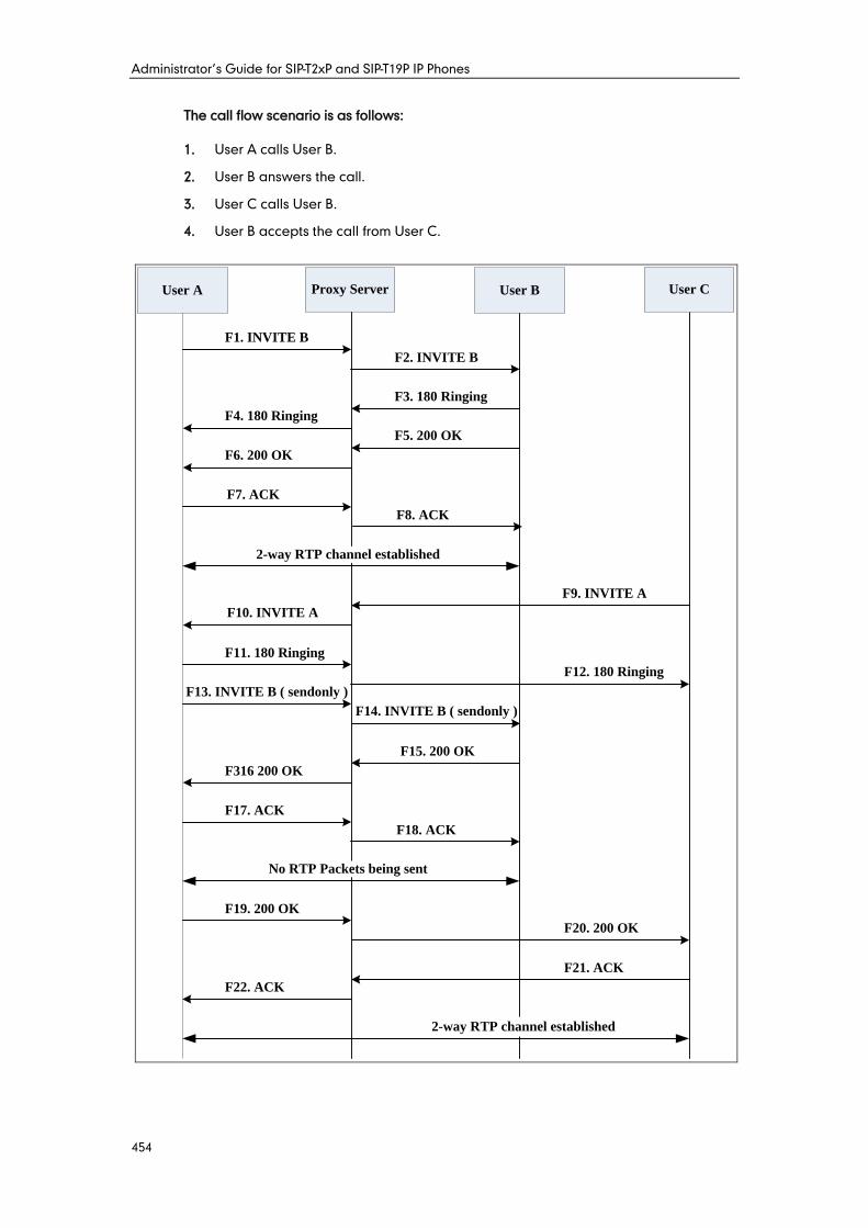
Administrator’s Guide for SIP-T2xP and SIP-T19P IP Phones
454
The call flow scenario is as follows:
1. User A calls User B.
2. User B answers the call.
3. User C calls User B.
4. User B accepts the call from User C.
F9. INVITE A
F11. 180 Ringing
F20. 200 OK
F1. INVITE B
F3. 180 Ringing
F5. 200 OK
F7. ACK
User A User B User CProxy Server
F2. INVITE B
F4. 180 Ringing
F6. 200 OK
F8. ACK
F10. INVITE A
F12. 180 Ringing
F13. INVITE B ( sendonly )
F15. 200 OK
F316 200 OK
F17. ACK
F18. ACK
F19. 200 OK
F21. ACK
F22. ACK
F14. INVITE B ( sendonly )
2-way RTP channel established
No RTP Packets being sent
2-way RTP channel established
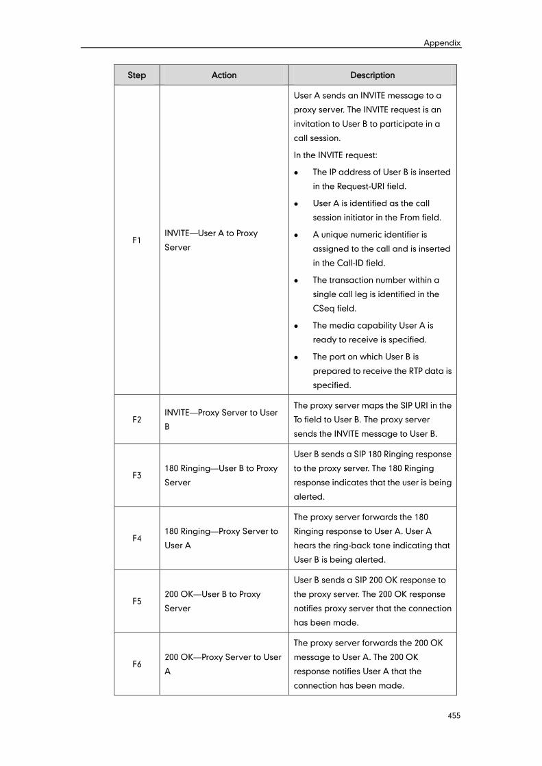
Appendix
455
Step Action Description
F1 INVITE—User A to Proxy
Server
User A sends an INVITE message to a
proxy server. The INVITE request is an
invitation to User B to participate in a
call session.
In the INVITE request:
The IP address of User B is inserted
in the Request-URI field.
User A is identified as the call
session initiator in the From field.
A unique numeric identifier is
assigned to the call and is inserted
in the Call-ID field.
The transaction number within a
single call leg is identified in the
CSeq field.
The media capability User A is
ready to receive is specified.
The port on which User B is
prepared to receive the RTP data is
specified.
F2 INVITE—Proxy Server to User
B
The proxy server maps the SIP URI in the
To field to User B. The proxy server
sends the INVITE message to User B.
F3 180 Ringing—User B to Proxy
Server
User B sends a SIP 180 Ringing response
to the proxy server. The 180 Ringing
response indicates that the user is being
alerted.
F4 180 Ringing—Proxy Server to
User A
The proxy server forwards the 180
Ringing response to User A. User A
hears the ring-back tone indicating that
User B is being alerted.
F5 200 OK—User B to Proxy
Server
User B sends a SIP 200 OK response to
the proxy server. The 200 OK response
notifies proxy server that the connection
has been made.
F6 200 OK—Proxy Server to User
A
The proxy server forwards the 200 OK
message to User A. The 200 OK
response notifies User A that the
connection has been made.
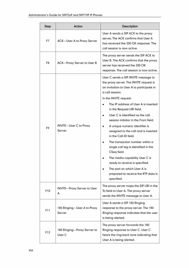
Administrator’s Guide for SIP-T2xP and SIP-T19P IP Phones
456
Step Action Description
F7 ACK—User A to Proxy Server
User A sends a SIP ACK to the proxy
server, The ACK confirms that User A
has received the 200 OK response. The
call session is now active.
F8 ACK—Proxy Server to User B
The proxy server sends the SIP ACK to
User B. The ACK confirms that the proxy
server has received the 200 OK
response. The call session is now active.
F9 INVITE—User C to Proxy
Server
User C sends a SIP INVITE message to
the proxy server. The INVITE request is
an invitation to User A to participate in
a call session.
In the INVITE request:
The IP address of User A is inserted
in the Request-URI field.
User C is identified as the call
session initiator in the From field.
A unique numeric identifier is
assigned to the call and is inserted
in the Call-ID field.
The transaction number within a
single call leg is identified in the
CSeq field.
The media capability User C is
ready to receive is specified.
The port on which User A is
prepared to receive the RTP data is
specified.
F10 INVITE—Proxy Server to User
A
The proxy server maps the SIP URI in the
To field to User A. The proxy server
sends the INVITE message to User A.
F11 180 Ringing—User A to Proxy
Server
User A sends a SIP 180 Ringing
response to the proxy server. The 180
Ringing response indicates that the user
is being alerted.
F12 180 Ringing—Proxy Server to
User C
The proxy server forwards the 180
Ringing response to User C. User C
hears the ring-back tone indicating that
User A is being alerted.

Appendix
457
Step Action Description
F13 INVITE—User A to Proxy
Server
User A sends a mid-call INVITE request
to the proxy server with new SDP
session parameters, which are used to
place the call on hold.
F14 INVITE—Proxy Server to User
B
The proxy server forwards the mid-call
INVITE message to User B.
F15 200 OK—User B to Proxy
Server
User B sends a 200 OK to the proxy
server. The 200 OK response indicates
that the INVITE was successfully
processed.
F16 200 OK—Proxy Server to User
A
The proxy server forwards the 200 OK
response to User A. The 200 OK
response notifies User B is successfully
placed on hold.
F17 ACK—User A to Proxy Server
User A sends an ACK message to the
proxy server. The ACK confirms that
User A has received the 200 OK
response. The call session is now
temporarily inactive. No RTP packets
are being sent.
F18 ACK—Proxy Server to User B
The proxy server sends the ACK
message to User B. The ACK confirms
that the proxy server has received the
200 OK response.
F19 200 OK—User A to Proxy
Server
User A sends a 200 OK response to the
proxy server. The 200 OK response
notifies that the connection has been
made.
F20 200 OK—Proxy Server User C The proxy server forwards the 200 OK
message to User C.
F21 ACK—User C to Proxy Server
User C sends a SIP ACK to the proxy
server. The ACK confirms that User C
has received the 200 OK response. The
call session is now active.
F22 ACK—Proxy Server to User A
The proxy server forwards the SIP ACK
to User A to confirm that User C has
received the 200 OK response.
Administrator’s Guide for SIP-T2xP and SIP-T19P IP Phones
458
The following figure illustrates a successful call between Yealink SIP IP phones in which
two parties are in a call and then one of the parties transfers the call to a third party
without consultation. This is called a blind transfer. In this call flow scenario, the end
users are User A, User B, and User C. They are all using Yealink SIP IP phones, which are
connected via an IP network.
The call flow scenario is as follows:
1. User A calls User B.
2. User B answers the call.
3. User B transfers the call to User C.
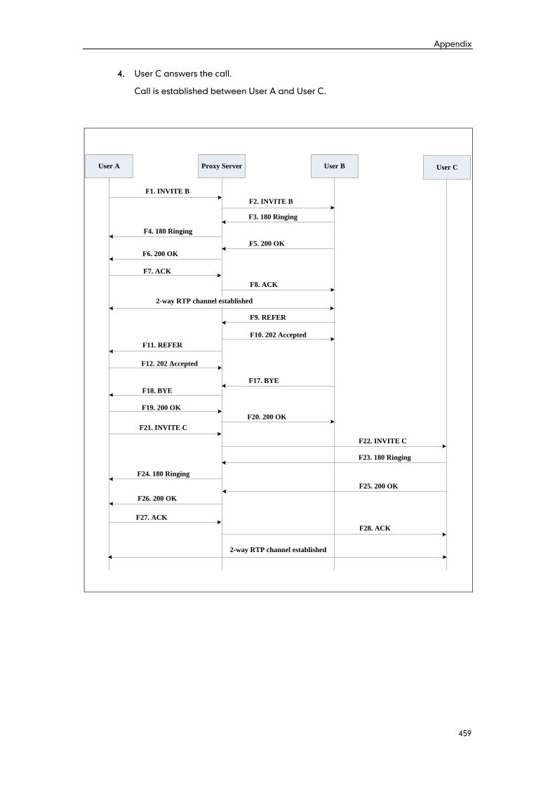
Appendix
459
4. User C answers the call.
Call is established between User A and User C.
User A Proxy Server User B
F1. INVITE B
F4. 180 Ringing
F6. 200 OK
F7. ACK
2-way RTP channel established
F23. 180 Ringing
F11. REFER
F12. 202 Accepted
F26. 200 OK
F2. INVITE B
F3. 180 Ringing
F5. 200 OK
F8. ACK
F22. INVITE C
F19. 200 OK
F27. ACK
F18. BYE
2-way RTP channel established
F9. REFER
F10. 202 Accepted
F17. BYE
F20. 200 OK
F21. INVITE C
F24. 180 Ringing
F25. 200 OK
F28. ACK
User C
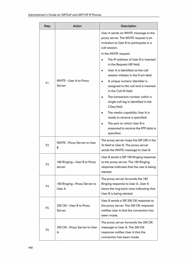
Administrator’s Guide for SIP-T2xP and SIP-T19P IP Phones
460
Step Action Description
F1 INVITE—User A to Proxy
Server
User A sends an INVITE message to the
proxy server. The INVITE request is an
invitation to User B to participate in a
call session.
In the INVITE request:
The IP address of User B is inserted
in the Request-URI field.
User A is identified as the call
session initiator in the From field.
A unique numeric identifier is
assigned to the call and is inserted
in the Call-ID field.
The transaction number within a
single call leg is identified in the
CSeq field.
The media capability User A is
ready to receive is specified.
The port on which User B is
prepared to receive the RTP data is
specified.
F2 INVITE—Proxy Server to User
B
The proxy server maps the SIP URI in the
To field to User B. The proxy server
sends the INVITE message to User B.
F3 180 Ringing—User B to Proxy
server
User B sends a SIP 180 Ringing response
to the proxy server. The 180 Ringing
response indicates that the user is being
alerted.
F4 180 Ringing—Proxy Server to
User A
The proxy server forwards the 180
Ringing response to User A. User A
hears the ring-back tone indicating that
User B is being alerted.
F5 200 OK—User B to Proxy
Server
User B sends a SIP 200 OK response to
the proxy server. The 200 OK response
notifies User A that the connection has
been made.
F6 200 OK—Proxy Server to User
A
The proxy server forwards the 200 OK
message to User A. The 200 OK
response notifies User A that the
connection has been made.
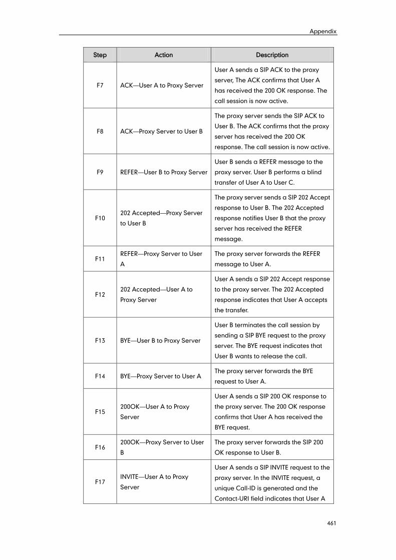
Appendix
461
Step Action Description
F7 ACK—User A to Proxy Server
User A sends a SIP ACK to the proxy
server, The ACK confirms that User A
has received the 200 OK response. The
call session is now active.
F8 ACK—Proxy Server to User B
The proxy server sends the SIP ACK to
User B. The ACK confirms that the proxy
server has received the 200 OK
response. The call session is now active.
F9 REFER—User B to Proxy Server
User B sends a REFER message to the
proxy server. User B performs a blind
transfer of User A to User C.
F10 202 Accepted—Proxy Server
to User B
The proxy server sends a SIP 202 Accept
response to User B. The 202 Accepted
response notifies User B that the proxy
server has received the REFER
message.
F11 REFER—Proxy Server to User
A
The proxy server forwards the REFER
message to User A.
F12 202 Accepted—User A to
Proxy Server
User A sends a SIP 202 Accept response
to the proxy server. The 202 Accepted
response indicates that User A accepts
the transfer.
F13 BYE—User B to Proxy Server
User B terminates the call session by
sending a SIP BYE request to the proxy
server. The BYE request indicates that
User B wants to release the call.
F14 BYE—Proxy Server to User A The proxy server forwards the BYE
request to User A.
F15 200OK—User A to Proxy
Server
User A sends a SIP 200 OK response to
the proxy server. The 200 OK response
confirms that User A has received the
BYE request.
F16 200OK—Proxy Server to User
B
The proxy server forwards the SIP 200
OK response to User B.
F17 INVITE—User A to Proxy
Server
User A sends a SIP INVITE request to the
proxy server. In the INVITE request, a
unique Call-ID is generated and the
Contact-URI field indicates that User A
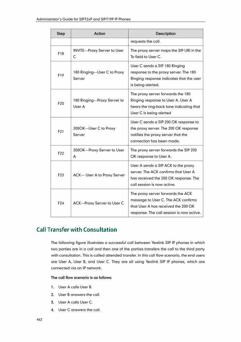
Administrator’s Guide for SIP-T2xP and SIP-T19P IP Phones
462
Step Action Description
requests the call.
F18 INVITE—Proxy Server to User
C
The proxy server maps the SIP URI in the
To field to User C.
F19 180 Ringing—User C to Proxy
Server
User C sends a SIP 180 Ringing
response to the proxy server. The 180
Ringing response indicates that the user
is being alerted.
F20 180 Ringing—Proxy Server to
User A
The proxy server forwards the 180
Ringing response to User A. User A
hears the ring-back tone indicating that
User C is being alerted
F21 200OK—User C to Proxy
Server
User C sends a SIP 200 OK response to
the proxy server. The 200 OK response
notifies the proxy server that the
connection has been made.
F22 200OK—Proxy Server to User
A
The proxy server forwards the SIP 200
OK response to User A.
F23 ACK— User A to Proxy Server
User A sends a SIP ACK to the proxy
server. The ACK confirms that User A
has received the 200 OK response. The
call session is now active.
F24 ACK—Proxy Server to User C
The proxy server forwards the ACK
message to User C. The ACK confirms
that User A has received the 200 OK
response. The call session is now active.
The following figure illustrates a successful call between Yealink SIP IP phones in which
two parties are in a call and then one of the parties transfers the call to the third party
with consultation. This is called attended transfer. In this call flow scenario, the end users
are User A, User B, and User C. They are all using Yealink SIP IP phones, which are
connected via an IP network.
The call flow scenario is as follows:
1. User A calls User B.
2. User B answers the call.
3. User A calls User C.
4. User C answers the call.
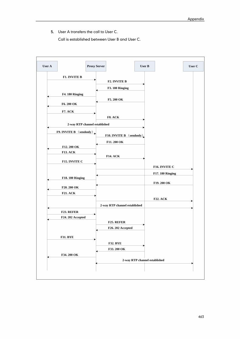
Appendix
463
5. User A transfers the call to User C.
Call is established between User B and User C.
User A Proxy Server User B
F1. INVITE B
F4. 180 Ringing
F6. 200 OK
F7. ACK
2-way RTP channel established
F9. INVITE B (sendonly)
F12. 200 OK
F13. ACK
F15. INVITE C
F17. 180 Ringing
F19. 200 OK
F21. ACK
F23. REFER
F24. 202 Accepted
User C
F2. INVITE B
F3. 180 Ringing
F5. 200 OK
F8. ACK
F10. INVITE B (sendonly)
F11. 200 OK
F14. ACK
F16. INVITE C
F18. 180 Ringing
F20. 200 OK
F22. ACK
2-way RTP channel established
F25. REFER
F26. 202 Accepted
F31. BYE
F32. BYE
F33. 200 OK
F34. 200 OK
2-way RTP channel established

Administrator’s Guide for SIP-T2xP and SIP-T19P IP Phones
464
Step Action Description
F1 INVITE—User A to Proxy
Server
User A sends an INVITE message to a
proxy server. The INVITE request is an
invitation to User B to participate in a
call session.
In the INVITE request:
The IP address of User B is inserted
in the Request-URI field.
User A is identified as the call
session initiator in the From field.
A unique numeric identifier is
assigned to the call and is inserted
in the Call-ID field.
The transaction number within a
single call leg is identified in the
CSeq field.
The media capability User A is
ready to receive is specified.
The port on which User B is
prepared to receive the RTP data is
specified.
F2 INVITE—Proxy Server to User
B
The proxy server maps the SIP URI in the
To field to User B. The proxy server
sends the INVITE message to User B.
F3 180 Ringing—User B to Proxy
Server
User B sends a SIP 180 Ringing response
to the proxy server. The 180 Ringing
response indicates that the user is being
alerted.
F4 180 Ringing—Proxy Server to
User A
The proxy server forwards the 180
Ringing response to User A. User A
hears the ring-back tone indicating that
User B is being alerted.
F5 200 OK—User B to Proxy
Server
User B sends a SIP 200 OK response to
the proxy server. The 200 OK response
notifies User A that the connection has
been made.
F6 200 OK—Proxy Server to User
A
The proxy server forwards the 200 OK
message to User A. The 200 OK
response notifies User A that the
connection has been made.
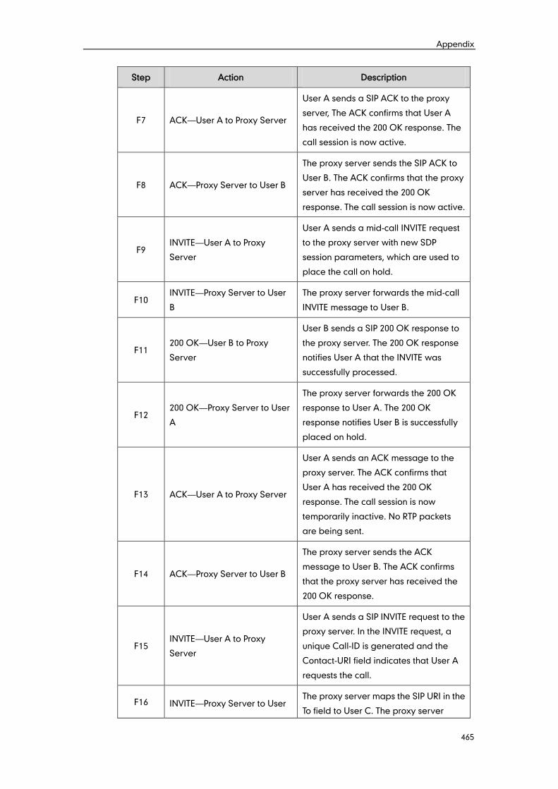
Appendix
465
Step Action Description
F7 ACK—User A to Proxy Server
User A sends a SIP ACK to the proxy
server, The ACK confirms that User A
has received the 200 OK response. The
call session is now active.
F8 ACK—Proxy Server to User B
The proxy server sends the SIP ACK to
User B. The ACK confirms that the proxy
server has received the 200 OK
response. The call session is now active.
F9 INVITE—User A to Proxy
Server
User A sends a mid-call INVITE request
to the proxy server with new SDP
session parameters, which are used to
place the call on hold.
F10 INVITE—Proxy Server to User
B
The proxy server forwards the mid-call
INVITE message to User B.
F11 200 OK—User B to Proxy
Server
User B sends a SIP 200 OK response to
the proxy server. The 200 OK response
notifies User A that the INVITE was
successfully processed.
F12 200 OK—Proxy Server to User
A
The proxy server forwards the 200 OK
response to User A. The 200 OK
response notifies User B is successfully
placed on hold.
F13 ACK—User A to Proxy Server
User A sends an ACK message to the
proxy server. The ACK confirms that
User A has received the 200 OK
response. The call session is now
temporarily inactive. No RTP packets
are being sent.
F14 ACK—Proxy Server to User B
The proxy server sends the ACK
message to User B. The ACK confirms
that the proxy server has received the
200 OK response.
F15 INVITE—User A to Proxy
Server
User A sends a SIP INVITE request to the
proxy server. In the INVITE request, a
unique Call-ID is generated and the
Contact-URI field indicates that User A
requests the call.
F16 INVITE—Proxy Server to User The proxy server maps the SIP URI in the
To field to User C. The proxy server
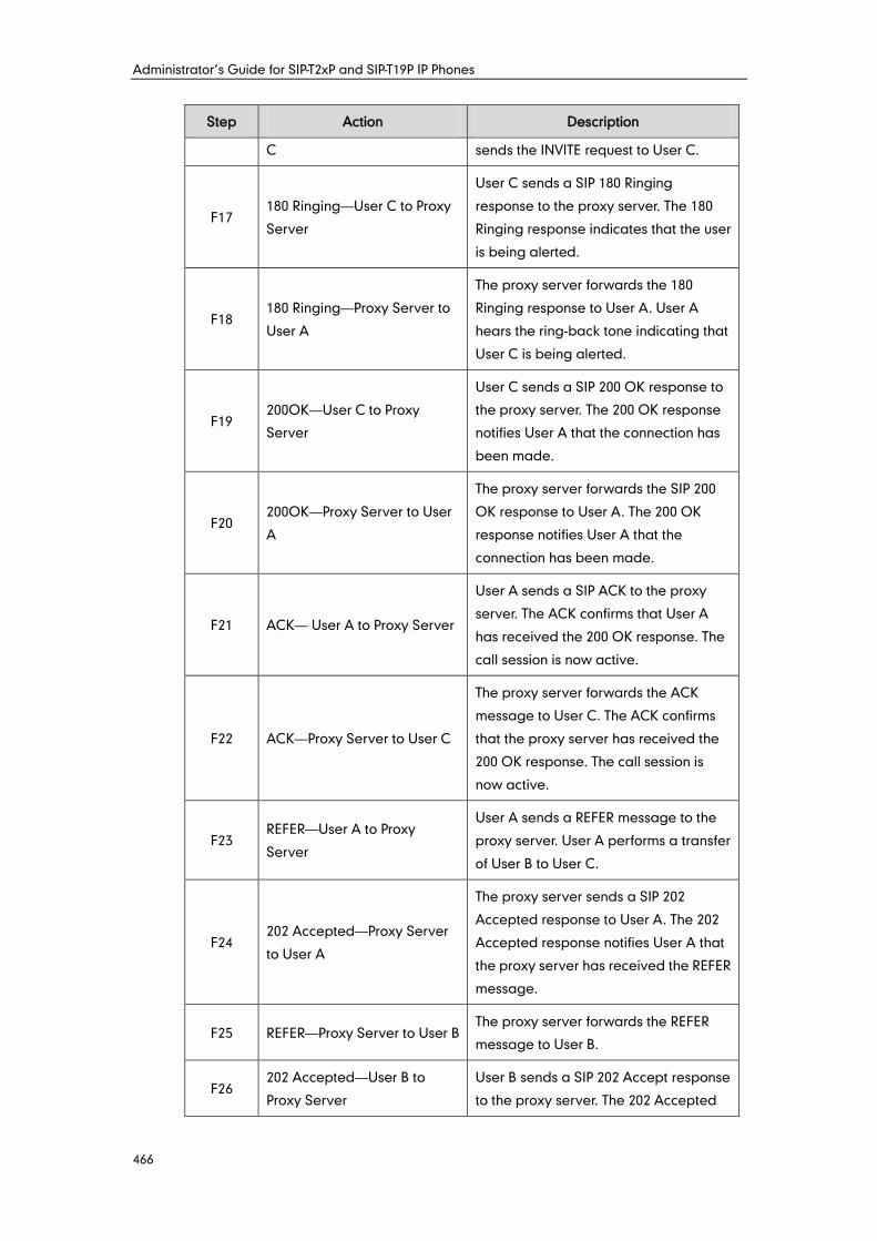
Administrator’s Guide for SIP-T2xP and SIP-T19P IP Phones
466
Step Action Description
C sends the INVITE request to User C.
F17 180 Ringing—User C to Proxy
Server
User C sends a SIP 180 Ringing
response to the proxy server. The 180
Ringing response indicates that the user
is being alerted.
F18 180 Ringing—Proxy Server to
User A
The proxy server forwards the 180
Ringing response to User A. User A
hears the ring-back tone indicating that
User C is being alerted.
F19 200OK—User C to Proxy
Server
User C sends a SIP 200 OK response to
the proxy server. The 200 OK response
notifies User A that the connection has
been made.
F20 200OK—Proxy Server to User
A
The proxy server forwards the SIP 200
OK response to User A. The 200 OK
response notifies User A that the
connection has been made.
F21 ACK— User A to Proxy Server
User A sends a SIP ACK to the proxy
server. The ACK confirms that User A
has received the 200 OK response. The
call session is now active.
F22 ACK—Proxy Server to User C
The proxy server forwards the ACK
message to User C. The ACK confirms
that the proxy server has received the
200 OK response. The call session is
now active.
F23 REFER—User A to Proxy
Server
User A sends a REFER message to the
proxy server. User A performs a transfer
of User B to User C.
F24 202 Accepted—Proxy Server
to User A
The proxy server sends a SIP 202
Accepted response to User A. The 202
Accepted response notifies User A that
the proxy server has received the REFER
message.
F25 REFER—Proxy Server to User B The proxy server forwards the REFER
message to User B.
F26 202 Accepted—User B to
Proxy Server
User B sends a SIP 202 Accept response
to the proxy server. The 202 Accepted
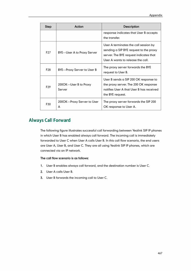
Appendix
467
Step Action Description
response indicates that User B accepts
the transfer.
F27 BYE—User A to Proxy Server
User A terminates the call session by
sending a SIP BYE request to the proxy
server. The BYE request indicates that
User A wants to release the call.
F28 BYE—Proxy Server to User B The proxy server forwards the BYE
request to User B.
F29 200OK—User B to Proxy
Server
User B sends a SIP 200 OK response to
the proxy server. The 200 OK response
notifies User A that User B has received
the BYE request.
F30 200OK—Proxy Server to User
A
The proxy server forwards the SIP 200
OK response to User A.
The following figure illustrates successful call forwarding between Yealink SIP IP phones
in which User B has enabled always call forward. The incoming call is immediately
forwarded to User C when User A calls User B. In this call flow scenario, the end users
are User A, User B, and User C. They are all using Yealink SIP IP phones, which are
connected via an IP network.
The call flow scenario is as follows:
1. User B enables always call forward, and the destination number is User C.
2. User A calls User B.
3. User B forwards the incoming call to User C.
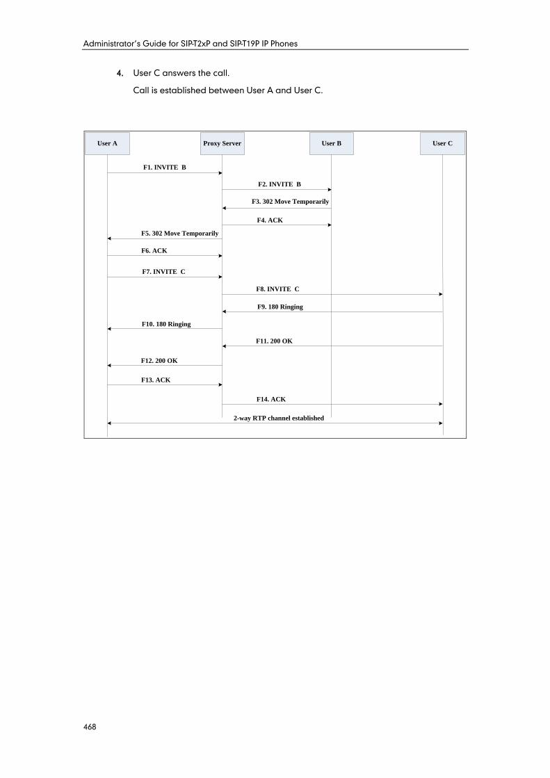
Administrator’s Guide for SIP-T2xP and SIP-T19P IP Phones
468
4. User C answers the call.
Call is established between User A and User C.
User A Proxy Server User B User C
F1. INVITE B
F2. INVITE B
F3. 302 Move Temporarily
F6. ACK
F7. INVITE C
F8. INVITE C
F9. 180 Ringing
F10. 180 Ringing
F11. 200 OK
F12. 200 OK
F13. ACK
F14. ACK
F4. ACK
2-way RTP channel established
F5. 302 Move Temporarily
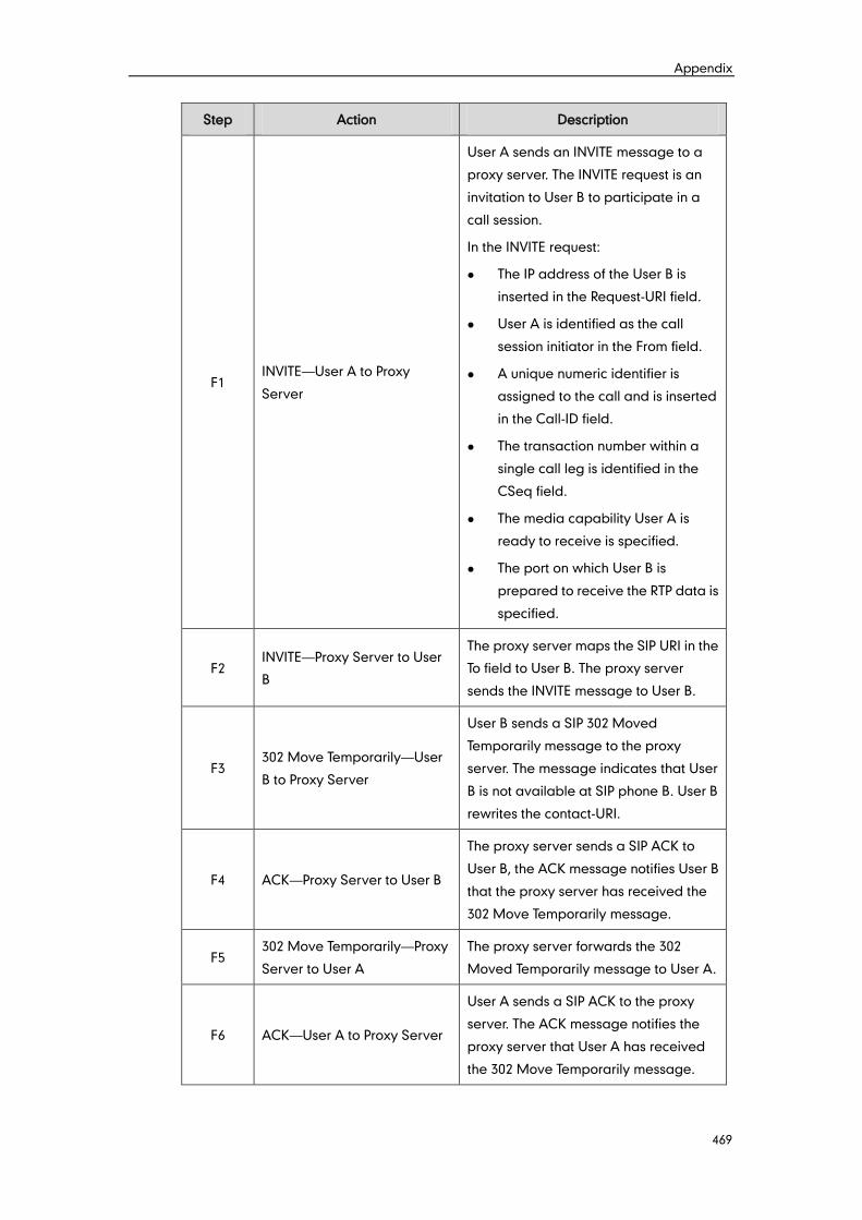
Appendix
469
Step Action Description
F1 INVITE—User A to Proxy
Server
User A sends an INVITE message to a
proxy server. The INVITE request is an
invitation to User B to participate in a
call session.
In the INVITE request:
The IP address of the User B is
inserted in the Request-URI field.
User A is identified as the call
session initiator in the From field.
A unique numeric identifier is
assigned to the call and is inserted
in the Call-ID field.
The transaction number within a
single call leg is identified in the
CSeq field.
The media capability User A is
ready to receive is specified.
The port on which User B is
prepared to receive the RTP data is
specified.
F2 INVITE—Proxy Server to User
B
The proxy server maps the SIP URI in the
To field to User B. The proxy server
sends the INVITE message to User B.
F3 302 Move Temporarily—User
B to Proxy Server
User B sends a SIP 302 Moved
Temporarily message to the proxy
server. The message indicates that User
B is not available at SIP phone B. User B
rewrites the contact-URI.
F4 ACK—Proxy Server to User B
The proxy server sends a SIP ACK to
User B, the ACK message notifies User B
that the proxy server has received the
302 Move Temporarily message.
F5 302 Move Temporarily—Proxy
Server to User A
The proxy server forwards the 302
Moved Temporarily message to User A.
F6 ACK—User A to Proxy Server
User A sends a SIP ACK to the proxy
server. The ACK message notifies the
proxy server that User A has received
the 302 Move Temporarily message.
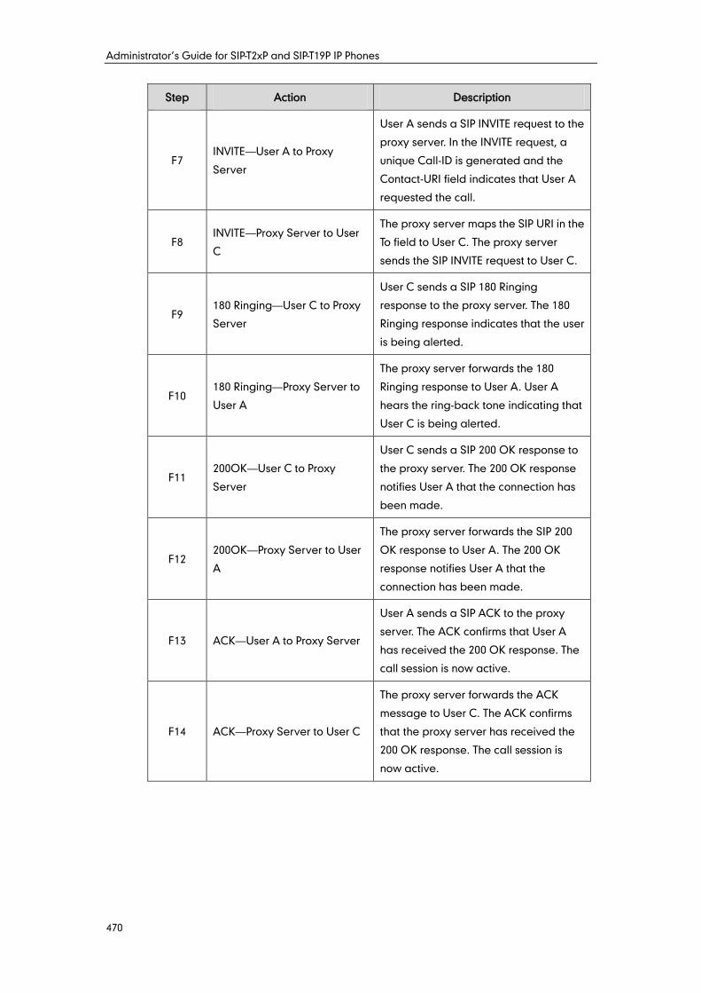
Administrator’s Guide for SIP-T2xP and SIP-T19P IP Phones
470
Step Action Description
F7 INVITE—User A to Proxy
Server
User A sends a SIP INVITE request to the
proxy server. In the INVITE request, a
unique Call-ID is generated and the
Contact-URI field indicates that User A
requested the call.
F8 INVITE—Proxy Server to User
C
The proxy server maps the SIP URI in the
To field to User C. The proxy server
sends the SIP INVITE request to User C.
F9 180 Ringing—User C to Proxy
Server
User C sends a SIP 180 Ringing
response to the proxy server. The 180
Ringing response indicates that the user
is being alerted.
F10 180 Ringing—Proxy Server to
User A
The proxy server forwards the 180
Ringing response to User A. User A
hears the ring-back tone indicating that
User C is being alerted.
F11 200OK—User C to Proxy
Server
User C sends a SIP 200 OK response to
the proxy server. The 200 OK response
notifies User A that the connection has
been made.
F12 200OK—Proxy Server to User
A
The proxy server forwards the SIP 200
OK response to User A. The 200 OK
response notifies User A that the
connection has been made.
F13 ACK—User A to Proxy Server
User A sends a SIP ACK to the proxy
server. The ACK confirms that User A
has received the 200 OK response. The
call session is now active.
F14 ACK—Proxy Server to User C
The proxy server forwards the ACK
message to User C. The ACK confirms
that the proxy server has received the
200 OK response. The call session is
now active.
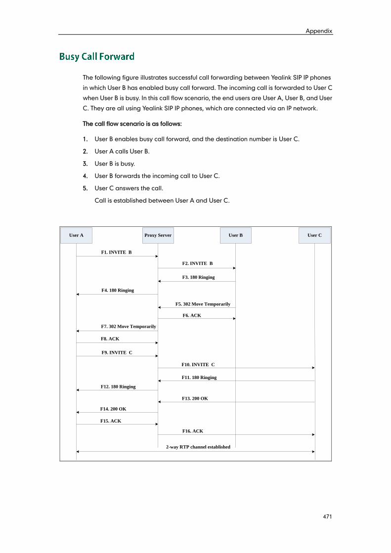
Appendix
471
The following figure illustrates successful call forwarding between Yealink SIP IP phones
in which User B has enabled busy call forward. The incoming call is forwarded to User C
when User B is busy. In this call flow scenario, the end users are User A, User B, and User
C. They are all using Yealink SIP IP phones, which are connected via an IP network.
The call flow scenario is as follows:
1. User B enables busy call forward, and the destination number is User C.
2. User A calls User B.
3. User B is busy.
4. User B forwards the incoming call to User C.
5. User C answers the call.
Call is established between User A and User C.
User A Proxy Server User B User C
F1. INVITE B
F2. INVITE B
F3. 180 Ringing
F8. ACK
F9. INVITE C
F10. INVITE C
F11. 180 Ringing
F12. 180 Ringing
F13. 200 OK
F14. 200 OK
F15. ACK
F16. ACK
F4. 180 Ringing
F5. 302 Move Temporarily
F6. ACK
F7. 302 Move Temporarily
2-way RTP channel established
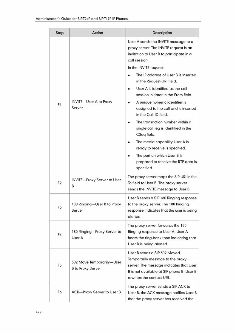
Administrator’s Guide for SIP-T2xP and SIP-T19P IP Phones
472
Step Action Description
F1 INVITE—User A to Proxy
Server
User A sends the INVITE message to a
proxy server. The INVITE request is an
invitation to User B to participate in a
call session.
In the INVITE request:
The IP address of User B is inserted
in the Request-URI field.
User A is identified as the call
session initiator in the From field.
A unique numeric identifier is
assigned to the call and is inserted
in the Call-ID field.
The transaction number within a
single call leg is identified in the
CSeq field.
The media capability User A is
ready to receive is specified.
The port on which User B is
prepared to receive the RTP data is
specified.
F2 INVITE—Proxy Server to User
B
The proxy server maps the SIP URI in the
To field to User B. The proxy server
sends the INVITE message to User B.
F3 180 Ringing—User B to Proxy
Server
User B sends a SIP 180 Ringing response
to the proxy server. The 180 Ringing
response indicates that the user is being
alerted.
F4 180 Ringing—Proxy Server to
User A
The proxy server forwards the 180
Ringing response to User A. User A
hears the ring-back tone indicating that
User B is being alerted.
F5 302 Move Temporarily—User
B to Proxy Server
User B sends a SIP 302 Moved
Temporarily message to the proxy
server. The message indicates that User
B is not available at SIP phone B. User B
rewrites the contact-URI.
F6 ACK—Proxy Server to User B
The proxy server sends a SIP ACK to
User B, the ACK message notifies User B
that the proxy server has received the
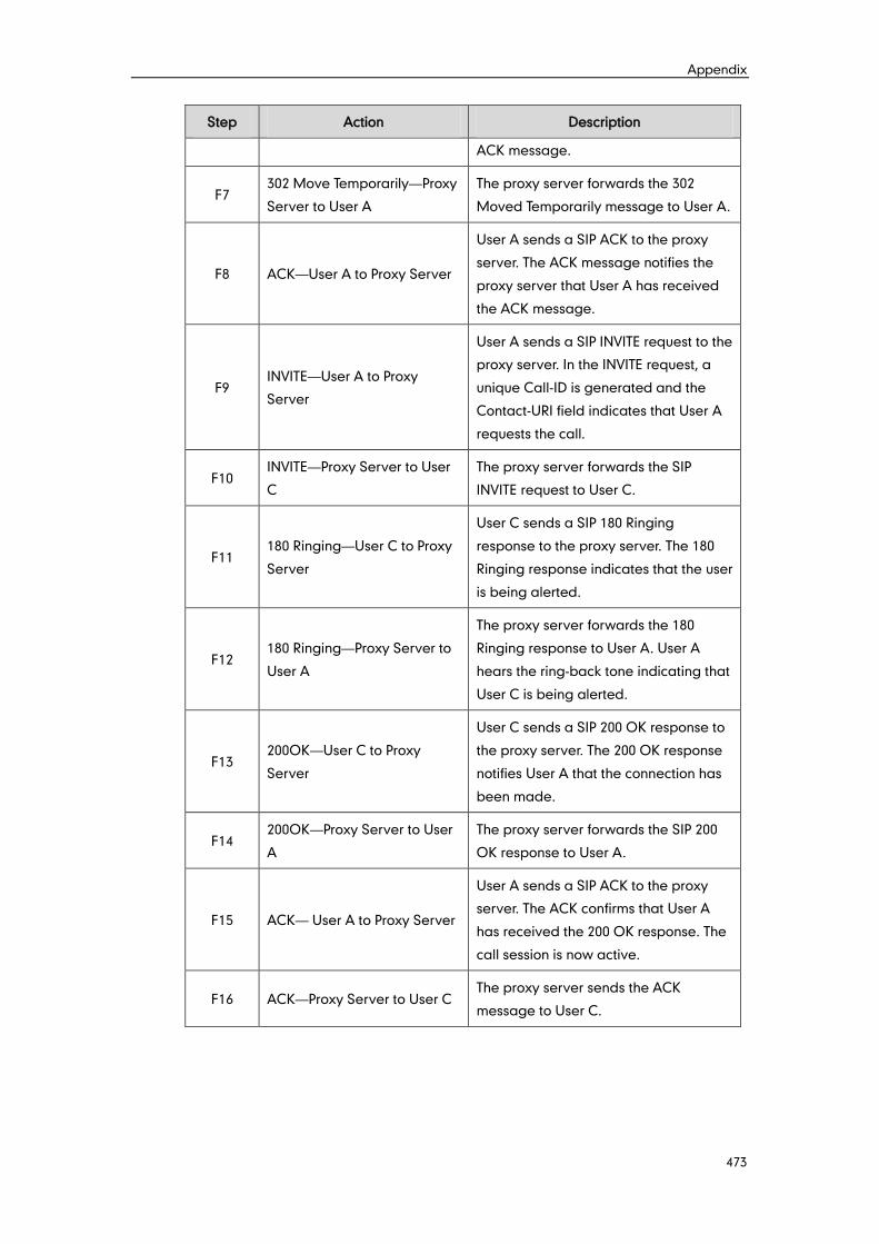
Appendix
473
Step Action Description
ACK message.
F7 302 Move Temporarily—Proxy
Server to User A
The proxy server forwards the 302
Moved Temporarily message to User A.
F8 ACK—User A to Proxy Server
User A sends a SIP ACK to the proxy
server. The ACK message notifies the
proxy server that User A has received
the ACK message.
F9 INVITE—User A to Proxy
Server
User A sends a SIP INVITE request to the
proxy server. In the INVITE request, a
unique Call-ID is generated and the
Contact-URI field indicates that User A
requests the call.
F10 INVITE—Proxy Server to User
C
The proxy server forwards the SIP
INVITE request to User C.
F11 180 Ringing—User C to Proxy
Server
User C sends a SIP 180 Ringing
response to the proxy server. The 180
Ringing response indicates that the user
is being alerted.
F12 180 Ringing—Proxy Server to
User A
The proxy server forwards the 180
Ringing response to User A. User A
hears the ring-back tone indicating that
User C is being alerted.
F13 200OK—User C to Proxy
Server
User C sends a SIP 200 OK response to
the proxy server. The 200 OK response
notifies User A that the connection has
been made.
F14 200OK—Proxy Server to User
A
The proxy server forwards the SIP 200
OK response to User A.
F15 ACK— User A to Proxy Server
User A sends a SIP ACK to the proxy
server. The ACK confirms that User A
has received the 200 OK response. The
call session is now active.
F16 ACK—Proxy Server to User C The proxy server sends the ACK
message to User C.
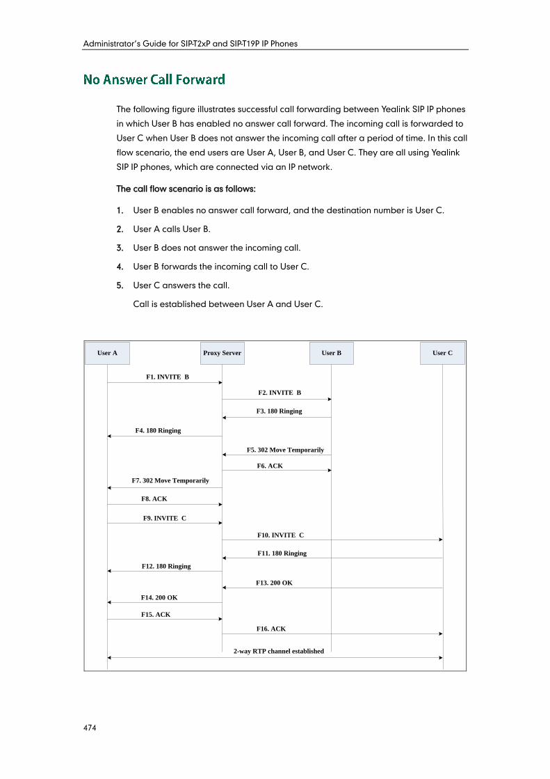
Administrator’s Guide for SIP-T2xP and SIP-T19P IP Phones
474
The following figure illustrates successful call forwarding between Yealink SIP IP phones
in which User B has enabled no answer call forward. The incoming call is forwarded to
User C when User B does not answer the incoming call after a period of time. In this call
flow scenario, the end users are User A, User B, and User C. They are all using Yealink
SIP IP phones, which are connected via an IP network.
The call flow scenario is as follows:
1. User B enables no answer call forward, and the destination number is User C.
2. User A calls User B.
3. User B does not answer the incoming call.
4. User B forwards the incoming call to User C.
5. User C answers the call.
Call is established between User A and User C.
User A Proxy Server User B User C
F1. INVITE B
F2. INVITE B
F3. 180 Ringing
F8. ACK
F9. INVITE C
F10. INVITE C
F11. 180 Ringing
F12. 180 Ringing
F13. 200 OK
F14. 200 OK
F15. ACK
F16. ACK
F4. 180 Ringing
F5. 302 Move Temporarily
F6. ACK
F7. 302 Move Temporarily
2-way RTP channel established
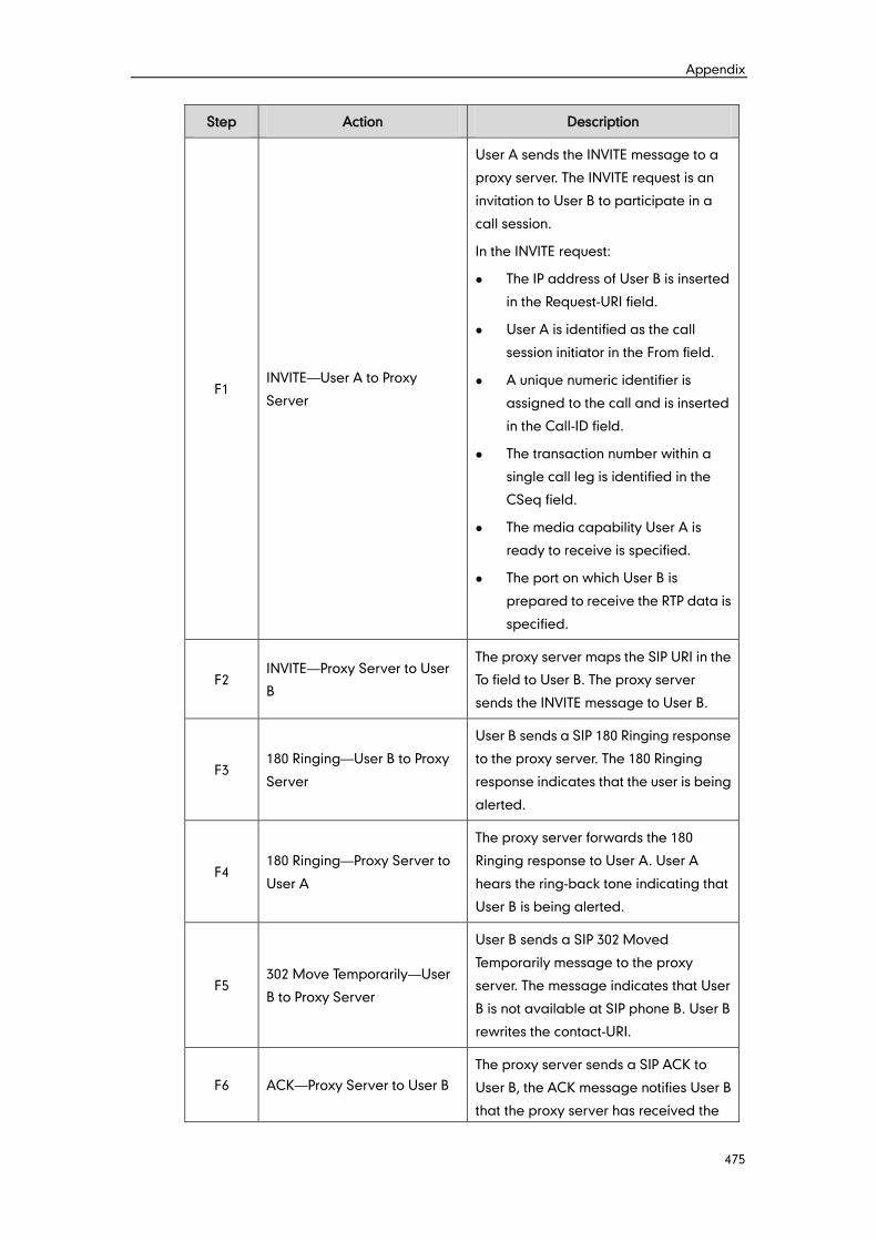
Appendix
475
Step Action Description
F1 INVITE—User A to Proxy
Server
User A sends the INVITE message to a
proxy server. The INVITE request is an
invitation to User B to participate in a
call session.
In the INVITE request:
The IP address of User B is inserted
in the Request-URI field.
User A is identified as the call
session initiator in the From field.
A unique numeric identifier is
assigned to the call and is inserted
in the Call-ID field.
The transaction number within a
single call leg is identified in the
CSeq field.
The media capability User A is
ready to receive is specified.
The port on which User B is
prepared to receive the RTP data is
specified.
F2 INVITE—Proxy Server to User
B
The proxy server maps the SIP URI in the
To field to User B. The proxy server
sends the INVITE message to User B.
F3 180 Ringing—User B to Proxy
Server
User B sends a SIP 180 Ringing response
to the proxy server. The 180 Ringing
response indicates that the user is being
alerted.
F4 180 Ringing—Proxy Server to
User A
The proxy server forwards the 180
Ringing response to User A. User A
hears the ring-back tone indicating that
User B is being alerted.
F5 302 Move Temporarily—User
B to Proxy Server
User B sends a SIP 302 Moved
Temporarily message to the proxy
server. The message indicates that User
B is not available at SIP phone B. User B
rewrites the contact-URI.
F6 ACK—Proxy Server to User B
The proxy server sends a SIP ACK to
User B, the ACK message notifies User B
that the proxy server has received the
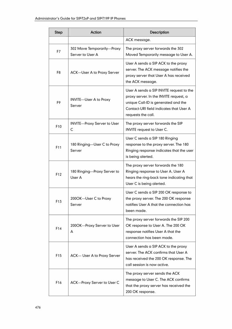
Administrator’s Guide for SIP-T2xP and SIP-T19P IP Phones
476
Step Action Description
ACK message.
F7 302 Move Temporarily—Proxy
Server to User A
The proxy server forwards the 302
Moved Temporarily message to User A.
F8 ACK—User A to Proxy Server
User A sends a SIP ACK to the proxy
server. The ACK message notifies the
proxy server that User A has received
the ACK message.
F9 INVITE—User A to Proxy
Server
User A sends a SIP INVITE request to the
proxy server. In the INVITE request, a
unique Call-ID is generated and the
Contact-URI field indicates that User A
requests the call.
F10 INVITE—Proxy Server to User
C
The proxy server forwards the SIP
INVITE request to User C.
F11 180 Ringing—User C to Proxy
Server
User C sends a SIP 180 Ringing
response to the proxy server. The 180
Ringing response indicates that the user
is being alerted.
F12 180 Ringing—Proxy Server to
User A
The proxy server forwards the 180
Ringing response to User A. User A
hears the ring-back tone indicating that
User C is being alerted.
F13 200OK—User C to Proxy
Server
User C sends a SIP 200 OK response to
the proxy server. The 200 OK response
notifies User A that the connection has
been made.
F14 200OK—Proxy Server to User
A
The proxy server forwards the SIP 200
OK response to User A. The 200 OK
response notifies User A that the
connection has been made.
F15 ACK— User A to Proxy Server
User A sends a SIP ACK to the proxy
server. The ACK confirms that User A
has received the 200 OK response. The
call session is now active.
F16 ACK—Proxy Server to User C
The proxy server sends the ACK
message to User C. The ACK confirms
that the proxy server has received the
200 OK response.
Appendix
477
The following figure illustrates successful 3-way calling between Yealink IP phones in
which User A mixes two RTP channels and therefore establishes a conference between
User B and User C. In this call flow scenario, the end users are User A, User B, and User
C. They are all using Yealink SIP IP phones, which are connected via an IP network.
The call flow scenario is as follows:
1. User A calls User B.
2. User B answers the call.
3. User A places User B on hold.
4. User A calls User C.
5. User C answers the call.
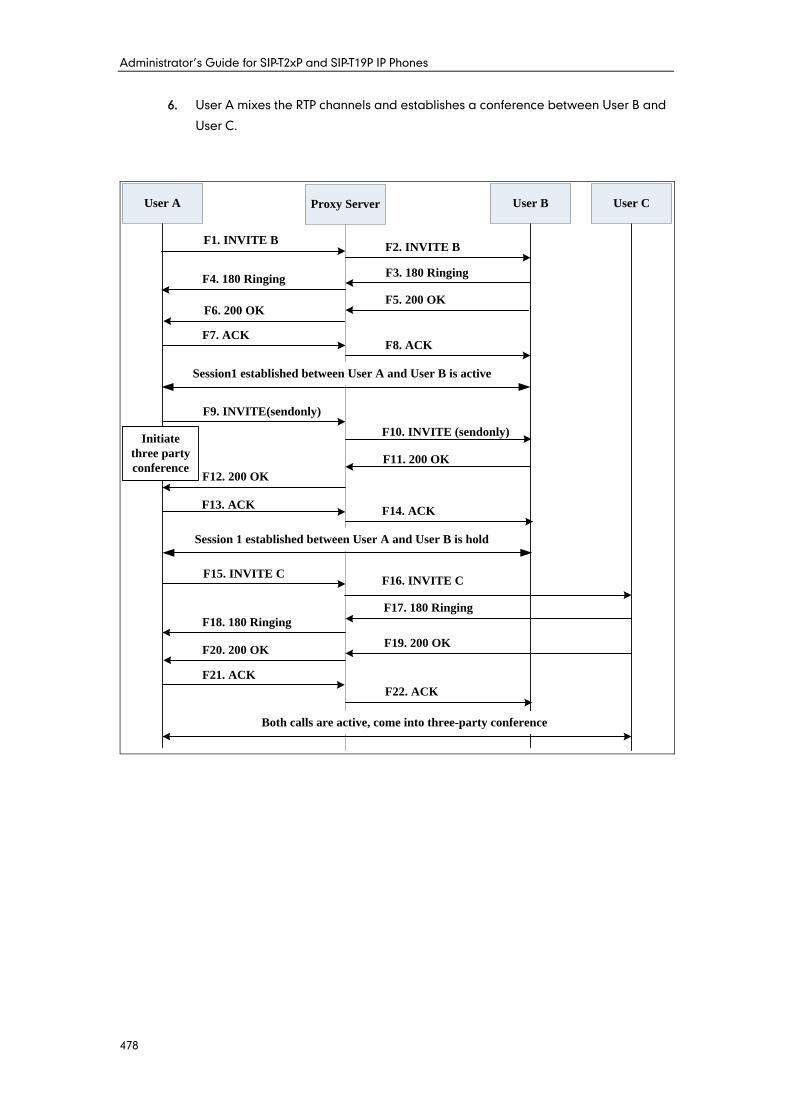
Administrator’s Guide for SIP-T2xP and SIP-T19P IP Phones
478
6. User A mixes the RTP channels and establishes a conference between User B and
User C.
F9. INVITE(sendonly)
F10. INVITE (sendonly)
F15. INVITE C
F11. 200 OK
F12. 200 OK
F1. INVITE BF2. INVITE B
F3. 180 RingingF4. 180 Ringing
F5. 200 OKF6. 200 OK
F7. ACKF8. ACK
Session1 established between User A and User B is active
F13. ACKF14. ACK
Session 1 established between User A and User B is hold
F16. INVITE C
F18. 180 Ringing
F17. 180 Ringing
F19. 200 OKF20. 200 OK
F21. ACK
F22. ACK
Both calls are active, come into three-party conference
User A Proxy Server User B User C
Initiate
three party
conference
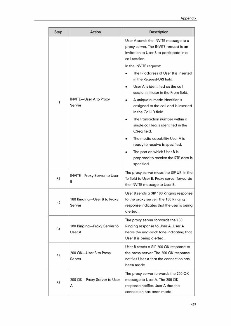
Appendix
479
Step Action Description
F1 INVITE—User A to Proxy
Server
User A sends the INVITE message to a
proxy server. The INVITE request is an
invitation to User B to participate in a
call session.
In the INVITE request:
The IP address of User B is inserted
in the Request-URI field.
User A is identified as the call
session initiator in the From field.
A unique numeric identifier is
assigned to the call and is inserted
in the Call-ID field.
The transaction number within a
single call leg is identified in the
CSeq field.
The media capability User A is
ready to receive is specified.
The port on which User B is
prepared to receive the RTP data is
specified.
F2 INVITE—Proxy Server to User
B
The proxy server maps the SIP URI in the
To field to User B. Proxy server forwards
the INVITE message to User B.
F3 180 Ringing—User B to Proxy
Server
User B sends a SIP 180 Ringing response
to the proxy server. The 180 Ringing
response indicates that the user is being
alerted.
F4 180 Ringing—Proxy Server to
User A
The proxy server forwards the 180
Ringing response to User A. User A
hears the ring-back tone indicating that
User B is being alerted.
F5 200 OK—User B to Proxy
Server
User B sends a SIP 200 OK response to
the proxy server. The 200 OK response
notifies User A that the connection has
been made.
F6 200 OK—Proxy Server to User
A
The proxy server forwards the 200 OK
message to User A. The 200 OK
response notifies User A that the
connection has been made.
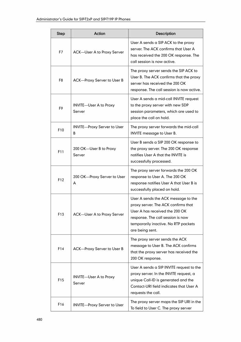
Administrator’s Guide for SIP-T2xP and SIP-T19P IP Phones
480
Step Action Description
F7 ACK—User A to Proxy Server
User A sends a SIP ACK to the proxy
server. The ACK confirms that User A
has received the 200 OK response. The
call session is now active.
F8 ACK—Proxy Server to User B
The proxy server sends the SIP ACK to
User B. The ACK confirms that the proxy
server has received the 200 OK
response. The call session is now active.
F9 INVITE—User A to Proxy
Server
User A sends a mid-call INVITE request
to the proxy server with new SDP
session parameters, which are used to
place the call on hold.
F10 INVITE—Proxy Server to User
B
The proxy server forwards the mid-call
INVITE message to User B.
F11 200 OK—User B to Proxy
Server
User B sends a SIP 200 OK response to
the proxy server. The 200 OK response
notifies User A that the INVITE is
successfully processed.
F12 200 OK—Proxy Server to User
A
The proxy server forwards the 200 OK
response to User A. The 200 OK
response notifies User A that User B is
successfully placed on hold.
F13 ACK—User A to Proxy Server
User A sends the ACK message to the
proxy server. The ACK confirms that
User A has received the 200 OK
response. The call session is now
temporarily inactive. No RTP packets
are being sent.
F14 ACK—Proxy Server to User B
The proxy server sends the ACK
message to User B. The ACK confirms
that the proxy server has received the
200 OK response.
F15 INVITE—User A to Proxy
Server
User A sends a SIP INVITE request to the
proxy server. In the INVITE request, a
unique Call-ID is generated and the
Contact-URI field indicates that User A
requests the call.
F16 INVITE—Proxy Server to User The proxy server maps the SIP URI in the
To field to User C. The proxy server
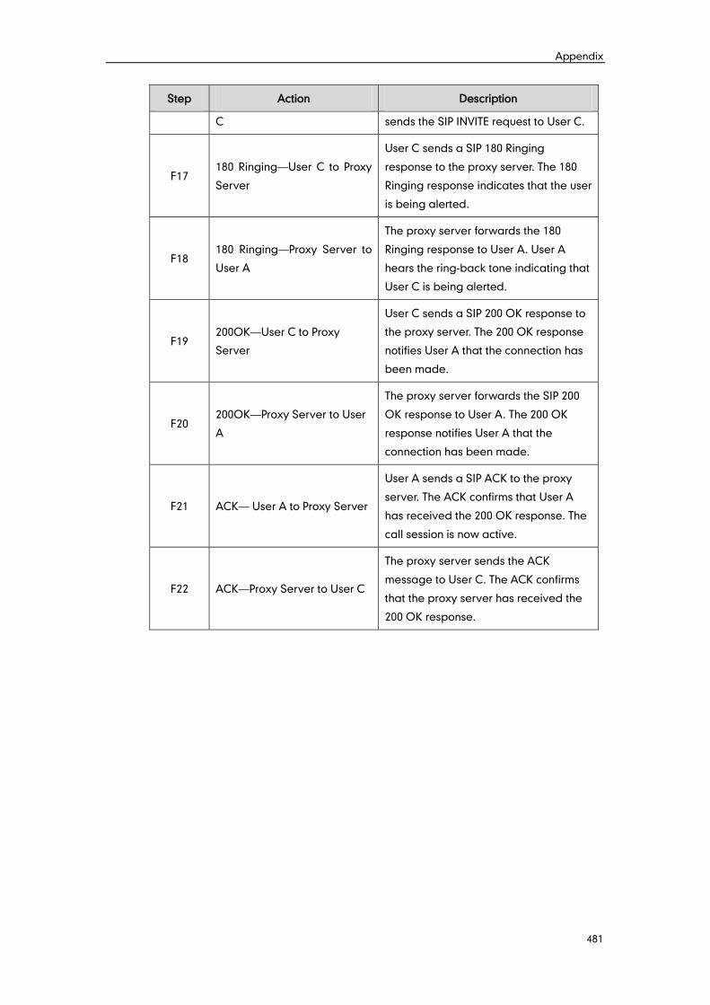
Appendix
481
Step Action Description
C sends the SIP INVITE request to User C.
F17 180 Ringing—User C to Proxy
Server
User C sends a SIP 180 Ringing
response to the proxy server. The 180
Ringing response indicates that the user
is being alerted.
F18 180 Ringing—Proxy Server to
User A
The proxy server forwards the 180
Ringing response to User A. User A
hears the ring-back tone indicating that
User C is being alerted.
F19 200OK—User C to Proxy
Server
User C sends a SIP 200 OK response to
the proxy server. The 200 OK response
notifies User A that the connection has
been made.
F20 200OK—Proxy Server to User
A
The proxy server forwards the SIP 200
OK response to User A. The 200 OK
response notifies User A that the
connection has been made.
F21 ACK— User A to Proxy Server
User A sends a SIP ACK to the proxy
server. The ACK confirms that User A
has received the 200 OK response. The
call session is now active.
F22 ACK—Proxy Server to User C
The proxy server sends the ACK
message to User C. The ACK confirms
that the proxy server has received the
200 OK response.
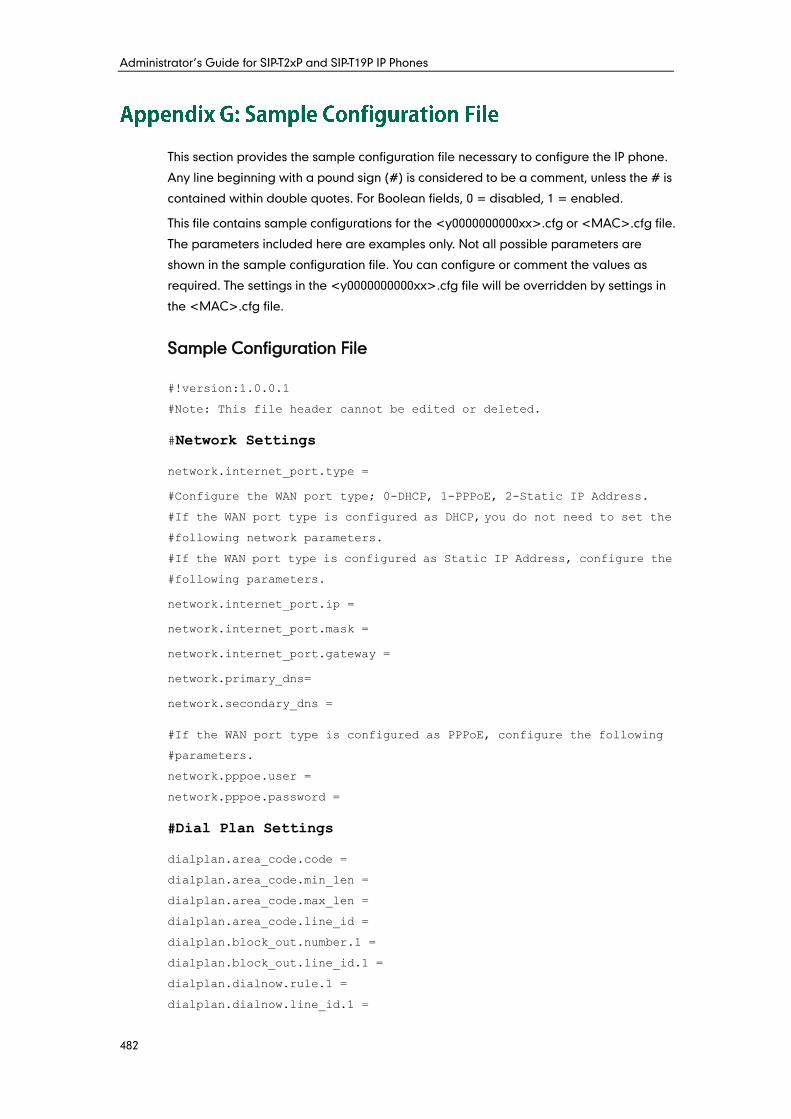
Administrator’s Guide for SIP-T2xP and SIP-T19P IP Phones
482
This section provides the sample configuration file necessary to configure the IP phone.
Any line beginning with a pound sign (#) is considered to be a comment, unless the # is
contained within double quotes. For Boolean fields, 0 = disabled, 1 = enabled.
This file contains sample configurations for the <y0000000000xx>.cfg or <MAC>.cfg file.
The parameters included here are examples only. Not all possible parameters are
shown in the sample configuration file. You can configure or comment the values as
required. The settings in the <y0000000000xx>.cfg file will be overridden by settings in
the <MAC>.cfg file.
Sample Configuration File
#!version:1.0.0.1
#Note: This file header cannot be edited or deleted.
#Network Settings
network.internet_port.type =
#Configure the WAN port type; 0-DHCP, 1-PPPoE, 2-Static IP Address.
#If the WAN port type is configured as DHCP, you do not need to set the
#following network parameters.
#If the WAN port type is configured as Static IP Address, configure the
#following parameters.
network.internet_port.ip =
network.internet_port.mask =
network.internet_port.gateway =
network.primary_dns=
network.secondary_dns =
#If the WAN port type is configured as PPPoE, configure the following
#parameters.
network.pppoe.user =
network.pppoe.password =
#Dial Plan Settings
dialplan.area_code.code =
dialplan.area_code.min_len =
dialplan.area_code.max_len =
dialplan.area_code.line_id =
dialplan.block_out.number.1 =
dialplan.block_out.line_id.1 =
dialplan.dialnow.rule.1 =
dialplan.dialnow.line_id.1 =
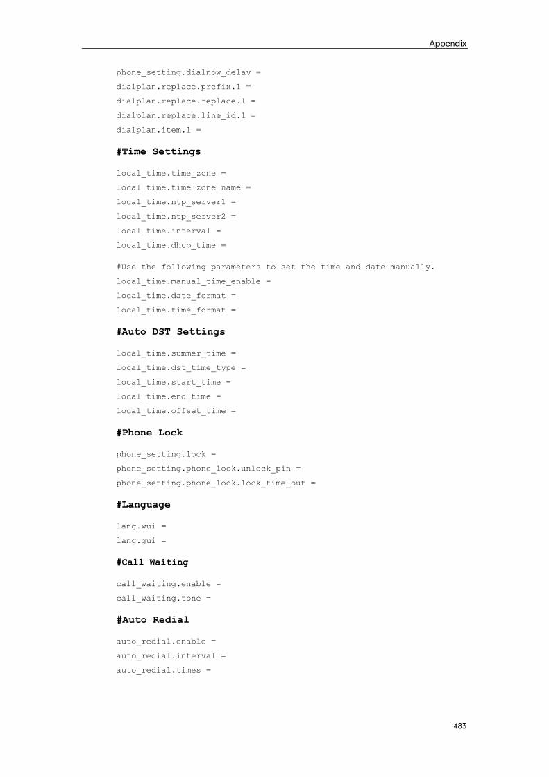
Appendix
483
phone_setting.dialnow_delay =
dialplan.replace.prefix.1 =
dialplan.replace.replace.1 =
dialplan.replace.line_id.1 =
dialplan.item.1 =
#Time Settings
local_time.time_zone =
local_time.time_zone_name =
local_time.ntp_server1 =
local_time.ntp_server2 =
local_time.interval =
local_time.dhcp_time =
#Use the following parameters to set the time and date manually.
local_time.manual_time_enable =
local_time.date_format =
local_time.time_format =
#Auto DST Settings
local_time.summer_time =
local_time.dst_time_type =
local_time.start_time =
local_time.end_time =
local_time.offset_time =
#Phone Lock
phone_setting.lock =
phone_setting.phone_lock.unlock_pin =
phone_setting.phone_lock.lock_time_out =
#Language
lang.wui =
lang.gui =
#Call Waiting
call_waiting.enable =
call_waiting.tone =
#Auto Redial
auto_redial.enable =
auto_redial.interval =
auto_redial.times =
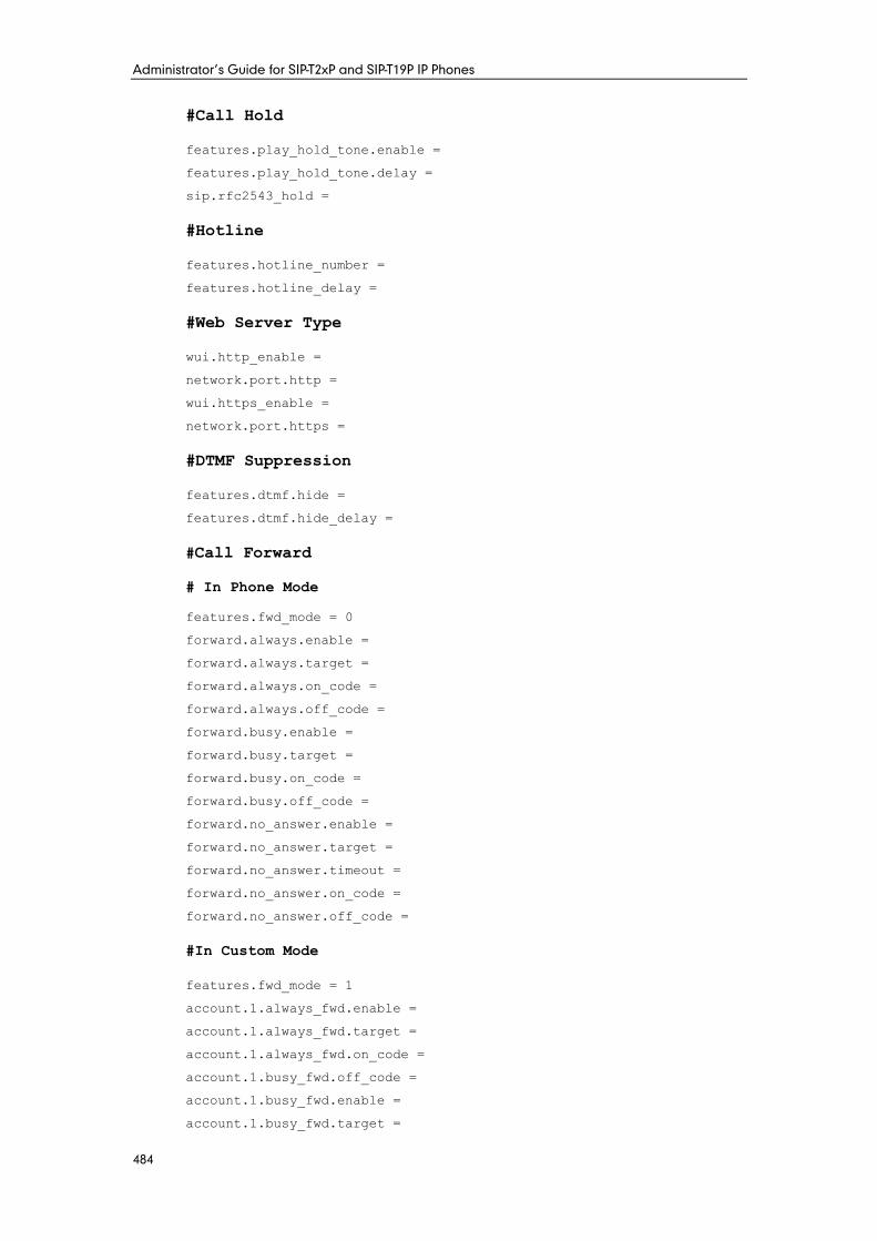
Administrator’s Guide for SIP-T2xP and SIP-T19P IP Phones
484
#Call Hold
features.play_hold_tone.enable =
features.play_hold_tone.delay =
sip.rfc2543_hold =
#Hotline
features.hotline_number =
features.hotline_delay =
#Web Server Type
wui.http_enable =
network.port.http =
wui.https_enable =
network.port.https =
#DTMF Suppression
features.dtmf.hide =
features.dtmf.hide_delay =
#Call Forward
# In Phone Mode
features.fwd_mode = 0
forward.always.enable =
forward.always.target =
forward.always.on_code =
forward.always.off_code =
forward.busy.enable =
forward.busy.target =
forward.busy.on_code =
forward.busy.off_code =
forward.no_answer.enable =
forward.no_answer.target =
forward.no_answer.timeout =
forward.no_answer.on_code =
forward.no_answer.off_code =
#In Custom Mode
features.fwd_mode = 1
account.1.always_fwd.enable =
account.1.always_fwd.target =
account.1.always_fwd.on_code =
account.1.busy_fwd.off_code =
account.1.busy_fwd.enable =
account.1.busy_fwd.target =
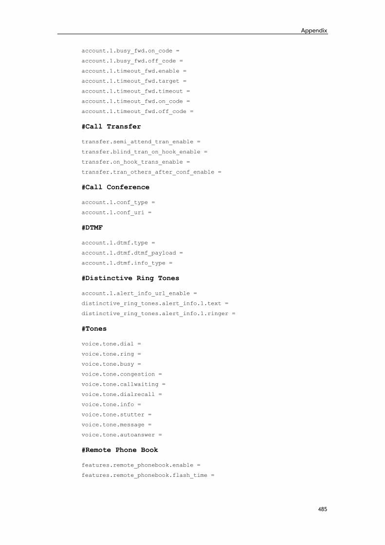
Appendix
485
account.1.busy_fwd.on_code =
account.1.busy_fwd.off_code =
account.1.timeout_fwd.enable =
account.1.timeout_fwd.target =
account.1.timeout_fwd.timeout =
account.1.timeout_fwd.on_code =
account.1.timeout_fwd.off_code =
#Call Transfer
transfer.semi_attend_tran_enable =
transfer.blind_tran_on_hook_enable =
transfer.on_hook_trans_enable =
transfer.tran_others_after_conf_enable =
#Call Conference
account.1.conf_type =
account.1.conf_uri =
#DTMF
account.1.dtmf.type =
account.1.dtmf.dtmf_payload =
account.1.dtmf.info_type =
#Distinctive Ring Tones
account.1.alert_info_url_enable =
distinctive_ring_tones.alert_info.1.text =
distinctive_ring_tones.alert_info.1.ringer =
#Tones
voice.tone.dial =
voice.tone.ring =
voice.tone.busy =
voice.tone.congestion =
voice.tone.callwaiting =
voice.tone.dialrecall =
voice.tone.info =
voice.tone.stutter =
voice.tone.message =
voice.tone.autoanswer =
#Remote Phone Book
features.remote_phonebook.enable =
features.remote_phonebook.flash_time =
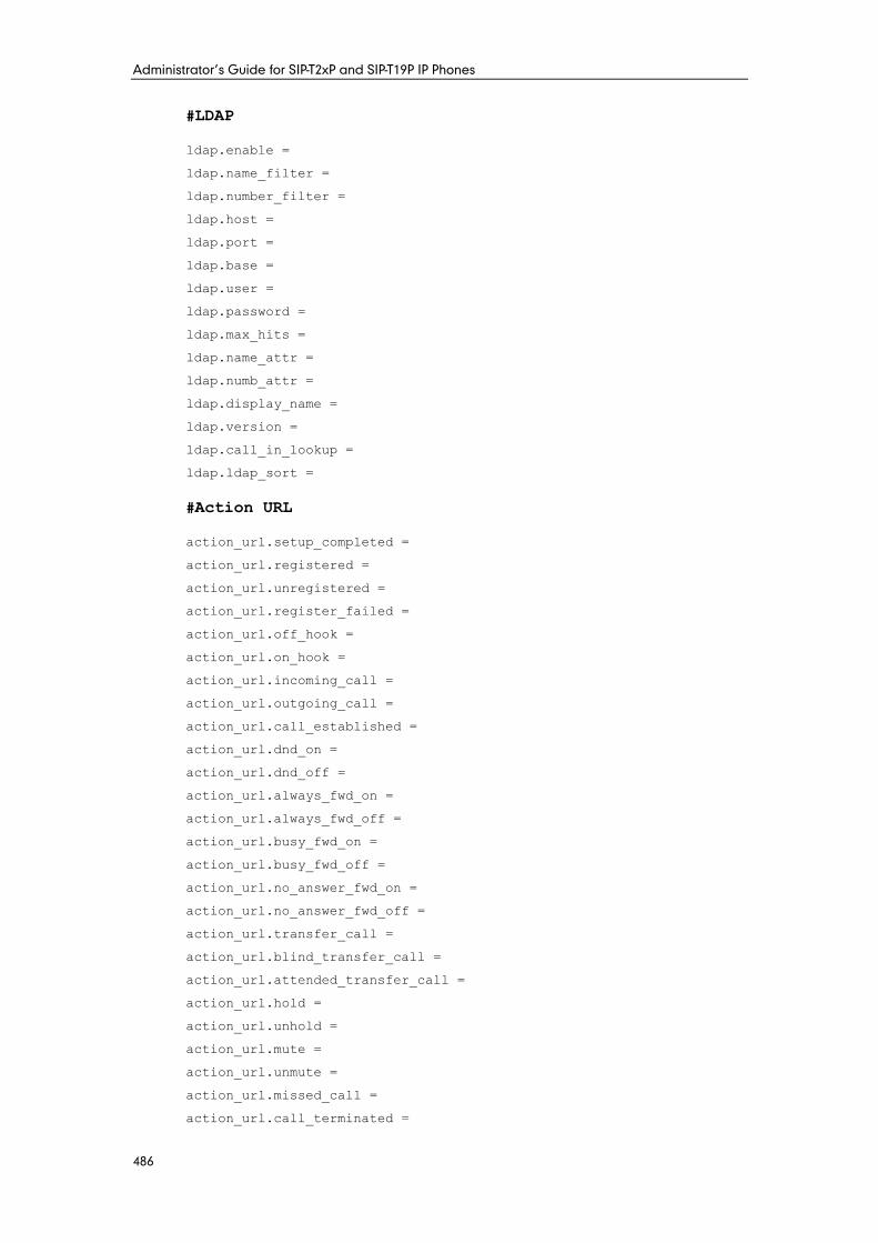
Administrator’s Guide for SIP-T2xP and SIP-T19P IP Phones
486
#LDAP
ldap.enable =
ldap.name_filter =
ldap.number_filter =
ldap.host =
ldap.port =
ldap.base =
ldap.user =
ldap.password =
ldap.max_hits =
ldap.name_attr =
ldap.numb_attr =
ldap.display_name =
ldap.version =
ldap.call_in_lookup =
ldap.ldap_sort =
#Action URL
action_url.setup_completed =
action_url.registered =
action_url.unregistered =
action_url.register_failed =
action_url.off_hook =
action_url.on_hook =
action_url.incoming_call =
action_url.outgoing_call =
action_url.call_established =
action_url.dnd_on =
action_url.dnd_off =
action_url.always_fwd_on =
action_url.always_fwd_off =
action_url.busy_fwd_on =
action_url.busy_fwd_off =
action_url.no_answer_fwd_on =
action_url.no_answer_fwd_off =
action_url.transfer_call =
action_url.blind_transfer_call =
action_url.attended_transfer_call =
action_url.hold =
action_url.unhold =
action_url.mute =
action_url.unmute =
action_url.missed_call =
action_url.call_terminated =
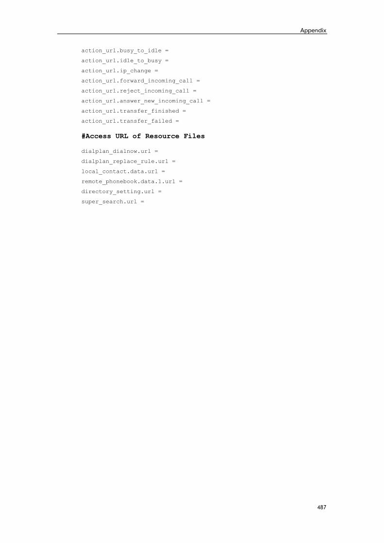
Appendix
487
action_url.busy_to_idle =
action_url.idle_to_busy =
action_url.ip_change =
action_url.forward_incoming_call =
action_url.reject_incoming_call =
action_url.answer_new_incoming_call =
action_url.transfer_finished =
action_url.transfer_failed =
#Access URL of Resource Files
dialplan_dialnow.url =
dialplan_replace_rule.url =
local_contact.data.url =
remote_phonebook.data.1.url =
directory_setting.url =
super_search.url =

Administrator’s Guide for SIP-T2xP and SIP-T19P IP Phones
488
Numeric
180 Ring Workaround 101
802.1X Authentication 199
A
About This Guide v
Acoustic Echo Cancellation 217
Action URL 173
Action URI 176
Administrator Password 46
Always Forward 110
Analyzing the Configuration Files 255
Anonymous Call 91
Anonymous Call Rejection 93
Appendix 264
Appendix A: Glossary 264
Appendix B: Time Zones 266
Appendix C: Configuration Parameters 268
Appendix D: SIP 434
Appendix E: SIP Call Flows 442
Appendix F: Sample Configuration File 482
Area Code 72
Attach the Stand 13
Attended Transfer 116
Audio Codecs 213
Auto Answer 88
Auto Redial 86
Automatic Call Distribution 159
B
Backlight 42
Blind Transfer 116
Block Out 73
Busy Forward 110
Busy Lamp Field 153
Busy Tone Delay 99
C
Call Completion 90
Call Forward 110
Call Hold 107
Call Log 75
Call Park 128
Call Recording 168
Call Return 127
Call Transfer 116
Call Waiting 84
Calling Line Identification Presentation 129
Connected Line Identification Presentation 131
Capturing Packets 253
Comfort Noise Generation 219
Configuration Files 20
Configuration Methods 18
Configuring Advanced features 141
Configuring Basic Features 37
Configuring Basic Network Parameters 22
Configuring Security Features 223
Connect the Network and Power 13
Connecting the IP phone 13
Contrast 40
Creating Dial Plan 67
D
Dial-now 69
Dial-now Template 239
Directed Call Pickup 119
Directory 75
Distinctive Ring Tones 141
Do Not Disturb (DND) 95
Documentations v
DTMF 132
Dual Headset 212
E
Early Media 101
Index
489
Encrypting Configuration Files 232
Enabling the Watch Dog Feature 254
G
Getting Information from Status Indicators 255
Getting Started 13
Group Call Pickup 122
H
H.323 1
Headset Prior 211
Hot Desking 172
Hotline 74
I
In This Guide v
Index 488
Initialization Process Overview 16
Intercom 137
IPv6 Support 206
J
Jitter Buffer 220
K
Key as Send 65
Key Features of IP Phones 10
L
Language 56
LDAP 150
Live Dialpad 84
LLDP 186
Loading Language Packs 57
Local Contact File 242
Local Directory 81
Logo Customization 59
M
Message Waiting Indicator 162
Missed Call Log 80
Multicast Paging 164
N
NAT Traversal 197
Network Address Translation (NAT) 197
Network Conference 117
No Answer Forward 110
P
Phone Lock 48
Phone User Interface 20
Physical Features of IP Phones 4
Power Indicator LED 38
Product Overview 1
Q
Quality of Service 195
R
Reading Icons 18
Remote Phone Book 148
Remote XML Phone Book 246
Replace Rule 68
Replace Rule Template 238
Return Message When DND 95
Return Code When Refuse 100
RFC and Internet Draft Support 434
S
Search Source List in Dialing 77
Semi-attended Transfer 116
Server Redundancy 179
Session Timer 105
SIP 434
SIP Components 2
SIP Header 437
SIP IP Phone Models 3
SIP Request 437
SIP Responses 439
SIP Session Description Protocol Usage 441
SIP Session Timer 104
Softkey Layout 62
Administrator’s Guide for SIP-T2xP and SIP-T19P IP Phones
490
Specifying the Language to Use 58
SRTP 229
STUN Server 197
Suppress DTMF Display 135
Summary of Changes vi
T
Table of Contents xi
Time and Date 50
Transfer on Conference Hang Up 118
Transfer via DTMF 136
Transport Layer Security (TLS) 223
Troubleshooting 250
Troubleshooting Methods 250
Troubleshooting Solutions 256
TR-069 Device Management 204
U
Upgrading Firmware 34
Use Outbound Proxy in Dialog 103
User Agent Client (UAC) 2
User Agent Server (UAS) 2
User Password 44
V
Verifying Startup 17
Viewing Log Files 250
VLAN 189
Voice Activity Detection 218
VoIP Principle 1
VPN 192
W
Web Server Type 44
Web User Interface 20


![[MS-SIP]: Session Initiation Protocol ExtensionsMS-SIP]-160714.pdf · [MS-SIP]: Session Initiation Protocol Extensions ... sip. . . .](https://img.dokumen.tips/doc/110x75/5f144311cb0953247f1ddd57/ms-sip-session-initiation-protocol-extensions-ms-sip-160714pdf-ms-sip.jpg)


