Embed Size (px)
Citation preview

Yaskawa MP Series Serial Driver
© 2021 PTC Inc. All Rights Reserved.
Yaskawa MP Series Serial Driver
Table of Contents
Yaskawa MP Series Serial Driver 1
Table of Contents 2
Yaskawa MP Series Serial Driver 4
Overview 4
Setup 5
Channel Properties — General 6
Channel Properties — Serial Communications 7
Channel Properties — Ethernet Encapsulation 9
Channel Properties — Write Optimizations 10
Channel Properties — Advanced 11
Device Properties — General 12
Operating Mode 13
Device Properties — Scan Mode 13
Device Properties — Timing 14
Device Properties — Auto-Demotion 15
Device Propert ies — Block Sizes 16
Device Properties — Redundancy 16
Data Types Description 17
Address Descriptions 18
MP Series Address Descript ions 18
GL Series Address Descript ions 19
Error Descriptions 21
Missing address 21
Device address '<address>' contains a syntax error 21
Address '<address>' is out of range for the specified device or register 22
Device address '<address>' is not supported by model '<model name>' 22
Data Type '<type>' is not valid for device address '<address>' 22
Device address '<address>' is Read Only 22
Array size is out of range for address '<address>' 22
Array support is not available for the specified address: '<address>' 23
Device '<device name>' is not responding 23
Unable to write to '<address>' on device '<device name>' 23
Device '<device>' responded with error '<Memobus error code>' (Tag '<tag>', Size '<bytes>') 24
Bad received length [<start address> to <end address>] on device '<device>' 24
Bad address in block [<start address> to <end address>] on device '<device>' 24
Device '<device>' block request [<start address> to <end address>] responded with exception 25
www.ptc.com
2

Yaskawa MP Series Serial Driver
<Memobus error code>
Index 26
www.ptc.com
3

Yaskawa MP Series Serial Driver
Yaskawa MP Series Serial DriverHelp version 1.026
CONTENTS
OverviewWhat is the Yaskawa MP Series Serial Driver?
SetupHow do I configure a device for use with this driver?
Data Types Descript ionWhat data types does the Yaskawa MP Series Serial Driver support?
Address Descript ionsHow do I reference a data location in a Yaskawa MP Series Serial Device?
Error Descript ionsWhat error messages does the Yaskawa MP Series Serial Driver produce?
OverviewThe Yaskawa MP Series Serial Driver provides an easy and reliable way to connect Yaskawa MP Series
Serial devices to OPC Client applications, including HMI, SCADA, Historian, MES, ERP and countless custom
applications. It supports the Yaskawa MP 900 series CPUs.
www.ptc.com
4

Yaskawa MP Series Serial Driver
Setup
Supported DevicesYaskawa MP SeriesYaskawa GL Series
Communication ProtocolMemobus RTU Protocol
Supported Communication PropertiesBaud Rate: 9600, 14400, 19200Parity: Even, Odd, NoneData Bits: 7, 8Stop Bits: 1, 2
Note: Settings should be chosen to match the hardware's configuration.
Ethernet EncapsulationThis driver supports Ethernet Encapsulation, which allows the driver to communicate with serial devices
attached to an Ethernet network using a terminal server (such as Digi One IA). It may be invoked through the
COM ID property group in Channel Properties.
Flow ControlWhen using an RS232 / RS485 converter, the type of flow control that is required depends on the needs of
the converter. Some converters do not require any flow control whereas others will require RTS flow. To
determine the converter's flow requirements, refer to its help documentation. An RS485 converter that
provides automatic flow control is recommended.
Channel and Device LimitsThe maximum number of channels supported by this driver is 100. The maximum number of devices sup-
ported by this driver is 8192 per channel.
Device IDEvery device on the network must have a unique network address. Set the Device ID driver property to
match the target device. The Device ID may range from 0 to 63.
Request TimeoutThis property specifies the time that the driver will wait on a response from the device before giving up and
going on to the next request. Longer timeouts only affect performance if a device is not responding. The
default setting is 1000 milliseconds. The valid range is 100 to 9999 milliseconds.
Retry AttemptsThis parameter specifies the number of times that the driver will retry a message before giving up and going
on to the next message. The default setting is 3 retries. The valid range is 1 to 10.
www.ptc.com
5

Yaskawa MP Series Serial Driver
Channel Propert ies — GeneralThis server supports the use of multiple simultaneous communications drivers. Each protocol or driver used
in a server project is called a channel. A server project may consist of many channels with the same com-
munications driver or with unique communications drivers. A channel acts as the basic building block of an
OPC link. This group is used to specify general channel properties, such as the identification attributes and
operating mode.
Identification
Name: Specify the user-defined identity of this channel. In each server project, each channel name must be
unique. Although names can be up to 256 characters, some client applications have a limited display window
when browsing the OPC server's tag space. The channel name is part of the OPC browser information. The
property is required for creating a channel.For information on reserved characters, refer to "How To... Properly Name a Channel, Device, Tag, and Tag
Group" in the server help.
Description: Specify user-defined information about this channel.
Many of these properties, including Description, have an associated system tag.
Driver: Specify the protocol / driver for this channel. This property specifies the device driver that was selec-
ted during channel creation. It is a disabled setting in the channel properties. The property is required for cre-
ating a channel.Note: With the server's online full-time operation, these properties can be changed at any time. This
includes changing the channel name to prevent clients from registering data with the server. If a client has
already acquired an item from the server before the channel name is changed, the items are unaffected. If,
after the channel name has been changed, the client application releases the item and attempts to re-
acquire using the old channel name, the item is not accepted. Changes to the properties should not be made
once a large client application has been developed. Utilize proper user role and privilege management to
prevent operators from changing properties or accessing server features.
Diagnostics
Diagnostics Capture: When enabled, this option makes the channel's diagnostic information available to
OPC applications allows the usage of statistics tags that provide feedback to client applications regarding
the operation of the channel. Because the server's diagnostic features require a minimal amount of over-
head processing, it is recommended that they be utilized when needed and disabled when not. The default is
disabled.Note: This property is not available if the driver does not support diagnostics.For more information, refer to "Communication Diagnostics" and "Statistics Tags" in the server help.
www.ptc.com
6

Yaskawa MP Series Serial Driver
Channel Propert ies — Serial CommunicationsSerial communication properties are available to serial drivers and vary depending on the driver, connection
type, and options selected. Below is a superset of the possible properties.Click to jump to one of the sections: Connection Type, Serial Port Settings or Ethernet Settings, and
Operational Behavior.
Note: With the server's online full-time operation, these properties can be changed at any time. Utilize
proper user role and privilege management to prevent operators from changing properties or accessing
server features.
Connection Type
Physical Medium : Choose the type of hardware device for data communications. Options include
COM Port, None, Modem, and Ethernet Encapsulation. The default is COM Port.
l None: Select None to indicate there is no physical connection, which displays the Operation with no
Communications section.
l COM Port : Select Com Port to display and configure the Serial Port Settings section.
l Modem : Select Modem if phone lines are used for communications, which are configured in the
Modem Settings section.
l Ethernet Encap.: Select if Ethernet Encapsulation is used for communications, which displays the
Ethernet Settings section.
l Shared: Verify the connection is correctly identified as sharing the current configuration with another
channel. This is a read-only property.
Serial Port Settings
COM ID: Specify the Communications ID to be used when communicating with devices assigned to the chan-
nel. The valid range is 1 to 9991 to 16. The default is 1.
Baud Rate: Specify the baud rate to be used to configure the selected communications port.
Data Bits: Specify the number of data bits per data word. Options include 5, 6, 7, or 8.
Parity: Specify the type of parity for the data. Options include Odd, Even, or None.
www.ptc.com
7
Yaskawa MP Series Serial Driver
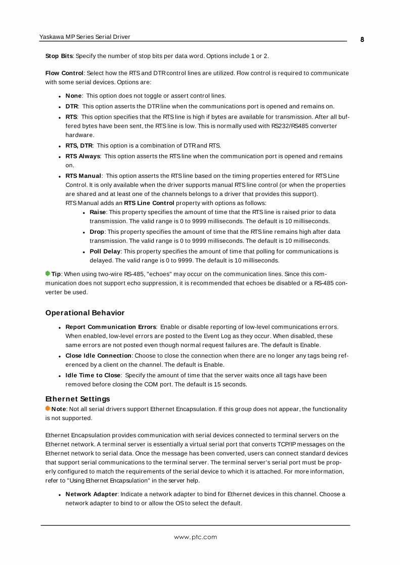
Stop Bits: Specify the number of stop bits per data word. Options include 1 or 2.
Flow Control: Select how the RTS and DTRcontrol lines are utilized. Flow control is required to communicate
with some serial devices. Options are:
l None: This option does not toggle or assert control lines.
l DTR: This option asserts the DTRline when the communications port is opened and remains on.
l RTS: This option specifies that the RTS line is high if bytes are available for transmission. After all buf-
fered bytes have been sent, the RTS line is low. This is normally used with RS232/RS485 converter
hardware.
l RTS, DTR: This option is a combination of DTRand RTS.
l RTS Always: This option asserts the RTS line when the communication port is opened and remains
on.
l RTS Manual: This option asserts the RTS line based on the timing properties entered for RTS Line
Control. It is only available when the driver supports manual RTS line control (or when the properties
are shared and at least one of the channels belongs to a driver that provides this support).
RTS Manual adds an RTS Line Control property with options as follows:
l Raise: This property specifies the amount of time that the RTS line is raised prior to data
transmission. The valid range is 0 to 9999 milliseconds. The default is 10 milliseconds.
l Drop: This property specifies the amount of time that the RTS line remains high after data
transmission. The valid range is 0 to 9999 milliseconds. The default is 10 milliseconds.
l Poll Delay: This property specifies the amount of time that polling for communications is
delayed. The valid range is 0 to 9999. The default is 10 milliseconds.
Tip: When using two-wire RS-485, "echoes" may occur on the communication lines. Since this com-
munication does not support echo suppression, it is recommended that echoes be disabled or a RS-485 con-
verter be used.
Operational Behavior
l Report Communication Errors: Enable or disable reporting of low-level communications errors.
When enabled, low-level errors are posted to the Event Log as they occur. When disabled, these
same errors are not posted even though normal request failures are. The default is Enable.
l Close Idle Connection: Choose to close the connection when there are no longer any tags being ref-
erenced by a client on the channel. The default is Enable.
l Idle Time to Close: Specify the amount of time that the server waits once all tags have been
removed before closing the COM port. The default is 15 seconds.
Ethernet SettingsNote: Not all serial drivers support Ethernet Encapsulation. If this group does not appear, the functionality
is not supported.
Ethernet Encapsulation provides communication with serial devices connected to terminal servers on the
Ethernet network. A terminal server is essentially a virtual serial port that converts TCP/IP messages on the
Ethernet network to serial data. Once the message has been converted, users can connect standard devices
that support serial communications to the terminal server. The terminal server's serial port must be prop-
erly configured to match the requirements of the serial device to which it is attached. For more information,
refer to "Using Ethernet Encapsulation" in the server help.
l Network Adapter: Indicate a network adapter to bind for Ethernet devices in this channel. Choose a
network adapter to bind to or allow the OS to select the default.
www.ptc.com
8

Yaskawa MP Series Serial Driver
Specific drivers may display additional Ethernet Encapsulation properties. For more information, refer
to Channel Properties — Ethernet Encapsulation.
Modem Settings
l Modem : Specify the installed modem to be used for communications.
l Connect Timeout : Specify the amount of time to wait for connections to be established before failing
a read or write. The default is 60 seconds.
l Modem Properties: Configure the modem hardware. When clicked, it opens vendor-specific modem
properties.
l Auto-Dial: Enables the automatic dialing of entries in the Phonebook. The default is Disable. For more
information, refer to "Modem Auto-Dial" in the server help.
l Report Communication Errors: Enable or disable reporting of low-level communications errors.
When enabled, low-level errors are posted to the Event Log as they occur. When disabled, these
same errors are not posted even though normal request failures are. The default is Enable.
l Close Idle Connection: Choose to close the modem connection when there are no longer any tags
being referenced by a client on the channel. The default is Enable.
l Idle Time to Close: Specify the amount of time that the server waits once all tags have been
removed before closing the modem connection. The default is 15 seconds.
Operation with no Communications
l Read Processing: Select the action to be taken when an explicit device read is requested. Options
include Ignore and Fail. Ignore does nothing; Fail provides the client with an update that indicates fail-
ure. The default setting is Ignore.
Channel Propert ies — Ethernet Encapsulat ionEthernet Encapsulation can be used over wireless network connections (such as 802.11b and CDPD packet
networks) and has also been developed to support a wide range of serial devices. With a terminal server
device, users can place RS-232 and RS-485 devices throughout the plant while still allowing a single localized
PC to access the remotely mounted devices. Ethernet Encapsulation also allows an individual network IP
address to be assigned to devices as needed. Multiple terminal servers provide users access to hundreds of
serial devices from a single PC. One channel can be defined to use the local PC serial port while another
channel can be defined to use Ethernet Encapsulation.Note: These properties are only available to serial drivers. The properties displayed depend on the selec-
ted communications driver and supported functionality.
Network Adapter: Specify the network adapter.
Device Address: Specify the four-field IP address of the terminal server to which this device is attached. IPs
are specified as YYY.YYY.YYY.YYY. The YYYdesignates the IP address: each YYYbyte should be in the range of 0
to 255. Each channel has its own IP address.
Port : Configure the Ethernet port that used when connecting to a remote terminal server. The valid range is
1 to 65535, with some numbers reserved. The default is 2101.
Protocol: Specify TCP/IP or UDP communication, which depends on the nature of the terminal server being
used. The default is TCP/IP. For more information on the protocol available, refer to the terminal server's help
documentation.
Important : The Ethernet Encapsulation mode is completely transparent to the actual serial
www.ptc.com
9

Yaskawa MP Series Serial Driver
communications driver. Users must configure the remaining device properties as if they were connecting to
the device directly on the local PC serial port.
Connect Timeout : Specify the amount of time that is required to establish a socket connection for a remote
device to be adjusted. In many cases, the connection time to a device can take longer than a normal com-
munications request to that same device. The valid range is 1 to 999 seconds. The default is 3 seconds.Note: With the server's online full-time operation, these properties can be changed at any time. Utilize
proper user role and privilege management to prevent operators from changing properties or accessing
server features.
Channel Propert ies — Write OptimizationsThe server must ensure that the data written from the client application gets to the device on time. Given
this goal, the server provides optimization properties to meet specific needs or improve application respons-
iveness.
Write Optimizations
Optimization Method: Controls how write data is passed to the underlying communications driver. The
options are:
l Write All Values for All Tags: This option forces the server to attempt to write every value to the
controller. In this mode, the server continues to gather write requests and add them to the server's
internal write queue. The server processes the write queue and attempts to empty it by writing data
to the device as quickly as possible. This mode ensures that everything written from the client applic-
ations is sent to the target device. This mode should be selected if the write operation order or the
write item's content must uniquely be seen at the target device.
l Write Only Latest Value for Non-Boolean Tags: Many consecutive writes to the same value can
accumulate in the write queue due to the time required to actually send the data to the device. If the
server updates a write value that has already been placed in the write queue, far fewer writes are
needed to reach the same final output value. In this way, no extra writes accumulate in the server's
queue. When the user stops moving the slide switch, the value in the device is at the correct value at
virtually the same time. As the mode states, any value that is not a Boolean value is updated in the
server's internal write queue and sent to the device at the next possible opportunity. This can greatly
improve the application performance.
Note: This option does not attempt to optimize writes to Boolean values. It allows users to optimize
the operation of HMI data without causing problems with Boolean operations, such as a momentary
push button.
l Write Only Latest Value for All Tags: This option takes the theory behind the second optimization
mode and applies it to all tags. It is especially useful if the application only needs to send the latest
value to the device. This mode optimizes all writes by updating the tags currently in the write queue
before they are sent. This is the default mode.
Duty Cycle: is used to control the ratio of write to read operations. The ratio is always based on one read for
every one to ten writes. The duty cycle is set to ten by default, meaning that ten writes occur for each read
operation. Although the application is performing a large number of continuous writes, it must be ensured
that read data is still given time to process. A setting of one results in one read operation for every write
www.ptc.com
10

Yaskawa MP Series Serial Driver
operation. If there are no write operations to perform, reads are processed continuously. This allows optim-
ization for applications with continuous writes versus a more balanced back and forth data flow.Note: It is recommended that the application be characterized for compatibility with the write optimization
enhancements before being used in a production environment.
Channel Propert ies — AdvancedThis group is used to specify advanced channel properties. Not all drivers support all properties; so the
Advanced group does not appear for those devices.
Non-Normalized Float Handling: A non-normalized value is defined as Infinity, Not-a-Number (NaN), or as
a Denormalized Number. The default is Replace with Zero. Drivers that have native float handling may
default to Unmodified. Non-normalized float handling allows users to specify how a driver handles non-nor-
malized IEEE-754 floating point data. Descriptions of the options are as follows:
l Replace with Zero: This option allows a driver to replace non-normalized IEEE-754 floating point val-
ues with zero before being transferred to clients.
l Unmodified: This option allows a driver to transfer IEEE-754 denormalized, normalized, non-num-
ber, and infinity values to clients without any conversion or changes.
Note: This property is not available if the driver does not support floating-point values or if it only supports
the option that is displayed. According to the channel's float normalization setting, only real-time driver tags
(such as values and arrays) are subject to float normalization. For example, EFM data is not affected by this
setting.
For more information on the floating-point values, refer to "How To ... Work with Non-Normalized Floating-
Point Values" in the server help.
Inter-Device Delay: Specify the amount of time the communications channel waits to send new requests to
the next device after data is received from the current device on the same channel. Zero (0) disables the
delay.
Note: This property is not available for all drivers, models, and dependent settings.
www.ptc.com
11

Yaskawa MP Series Serial Driver
Device Propert ies — GeneralA device represents a single target on a communications channel. If the driver supports multiple controllers,
users must enter a device ID for each controller.
Identification
Name: Specify the name of the device. It is a logical user-defined name that can be up to 256 characters
long and may be used on multiple channels.
Note: Although descriptive names are generally a good idea, some OPC client applications may have a
limited display window when browsing the OPC server's tag space. The device name and channel name
become part of the browse tree information as well. Within an OPC client, the combination of channel name
and device name would appear as "ChannelName.DeviceName".For more information, refer to "How To... Properly Name a Channel, Device, Tag, and Tag Group" in server
help.
Description: Specify the user-defined information about this device.
Many of these properties, including Description, have an associated system tag.
Channel Assignment : Specify the user-defined name of the channel to which this device currently belongs.
Driver: Selected protocol driver for this device.
Model: Specify the type of device that is associated with this ID. The contents of the drop-down menu
depend on the type of communications driver being used. Models that are not supported by a driver are dis-
abled. If the communications driver supports multiple device models, the model selection can only be
changed when there are no client applications connected to the device.Note: If the communication driver supports multiple models, users should try to match the model selec-
tion to the physical device. If the device is not represented in the drop-down menu, select a model that con-
forms closest to the target device. Some drivers support a model selection called "Open," which allows users
to communicate without knowing the specific details of the target device. For more information, refer to the
driver help documentation.
ID: Specify the device's driver-specific station or node. The type of ID entered depends on the com-
munications driver being used. For many communication drivers, the ID is a numeric value. Drivers that sup-
port a Numeric ID provide users with the option to enter a numeric value whose format can be changed to
suit the needs of the application or the characteristics of the selected communications driver. The format is
set by the driver by default. Options include Decimal, Octal, and Hexadecimal.Note: If the driver is Ethernet-based or supports an unconventional station or node name, the device's
TCP/IP address may be used as the device ID. TCP/IP addresses consist of four values that are separated by
periods, with each value in the range of 0 to 255. Some device IDs are string based. There may be additional
www.ptc.com
12

Yaskawa MP Series Serial Driver
properties to configure within the ID field, depending on the driver. For more information, refer to the driver's
help documentation.
Operating Mode
Data Collection: This property controls the device's active state. Although device communications are
enabled by default, this property can be used to disable a physical device. Communications are not attemp-
ted when a device is disabled. From a client standpoint, the data is marked as invalid and write operations
are not accepted. This property can be changed at any time through this property or the device system tags.
Simulated: Place the device into or out of Simulation Mode. In this mode, the driver does not attempt to
communicate with the physical device, but the server continues to return valid OPC data. Simulated stops
physical communications with the device, but allows OPC data to be returned to the OPC client as valid data.
While in Simulation Mode, the server treats all device data as reflective: whatever is written to the simulated
device is read back and each OPC item is treated individually. The item's memory map is based on the group
Update Rate. The data is not saved if the server removes the item (such as when the server is reinitialized).
The default is No.Notes:
1. This System tag (_Simulated) is read only and cannot be written to for runtime protection. The System
tag allows this property to be monitored from the client.
2. In Simulation mode, the item's memory map is based on client update rate(s) (Group Update Rate for
OPC clients or Scan Rate for native and DDE interfaces). This means that two clients that reference
the same item with different update rates return different data.
Simulation Mode is for test and simulation purposes only. It should never be used in a production envir-
onment.
Device Propert ies — Scan ModeThe Scan Mode specifies the subscribed-client requested scan rate for tags that require device com-
munications. Synchronous and asynchronous device reads and writes are processed as soon as possible;
unaffected by the Scan Mode properties.
Scan Mode: Specify how tags in the device are scanned for updates sent to subscribing clients. Descriptions
of the options are:
l Respect Client-Specified Scan Rate: This mode uses the scan rate requested by the client.l Request Data No Faster than Scan Rate: This mode specifies the value set as the maximum scan
rate. The valid range is 10 to 99999990 milliseconds. The default is 1000 milliseconds.
Note: When the server has an active client and items for the device and the scan rate value is
www.ptc.com
13

Yaskawa MP Series Serial Driver
increased, the changes take effect immediately. When the scan rate value is decreased, the changes
do not take effect until all client applications have been disconnected.
l Request All Data at Scan Rate: This mode forces tags to be scanned at the specified rate for sub-
scribed clients. The valid range is 10 to 99999990 milliseconds. The default is 1000 milliseconds.
l Do Not Scan, Demand Poll Only: This mode does not periodically poll tags that belong to the
device nor perform a read to get an item's initial value once it becomes active. It is the OPC client's
responsibility to poll for updates, either by writing to the _DemandPoll tag or by issuing explicit device
reads for individual items. For more information, refer to "Device Demand Poll" in server help.
l Respect Tag-Specified Scan Rate: This mode forces static tags to be scanned at the rate specified
in their static configuration tag properties. Dynamic tags are scanned at the client-specified scan
rate.
Initial Updates from Cache: When enabled, this option allows the server to provide the first updates for
newly activated tag references from stored (cached) data. Cache updates can only be provided when the
new item reference shares the same address, scan rate, data type, client access, and scaling properties. A
device read is used for the initial update for the first client reference only. The default is disabled; any time a
client activates a tag reference the server attempts to read the initial value from the device.
Device Propert ies — TimingThe device Timing properties allow the driver's response to error conditions to be tailored to fit the applic-
ation's needs. In many cases, the environment requires changes to these properties for optimum per-
formance. Factors such as electrically generated noise, modem delays, and poor physical connections can
influence how many errors or timeouts a communications driver encounters. Timing properties are specific
to each configured device.
Communications TimeoutsConnect Timeout : This property (which is used primarily by Ethernet based drivers) controls the amount of
time required to establish a socket connection to a remote device. The device's connection time often takes
longer than normal communications requests to that same device. The valid range is 1 to 30 seconds. The
default is typically 3 seconds, but can vary depending on the driver's specific nature. If this setting is not sup-
ported by the driver, it is disabled.Note: Due to the nature of UDP connections, the connection timeout setting is not applicable when com-
municating via UDP.
Request Timeout : Specify an interval used by all drivers to determine how long the driver waits for a
response from the target device to complete. The valid range is 50 to 9,999,999 milliseconds (167.6667
minutes). The default is usually 1000 milliseconds, but can vary depending on the driver. The default timeout
for most serial drivers is based on a baud rate of 9600 baud or better. When using a driver at lower baud
rates, increase the timeout to compensate for the increased time required to acquire data.
Attempts Before Timeout : Specify how many times the driver issues a communications request before con-
sidering the request to have failed and the device to be in error. The valid range is 1 to 10. The default is
www.ptc.com
14

Yaskawa MP Series Serial Driver
typically 3, but can vary depending on the driver's specific nature. The number of attempts configured for an
application depends largely on the communications environment. This property applies to both connection
attempts and request attempts.
TimingInter-Request Delay: Specify how long the driver waits before sending the next request to the target
device. It overrides the normal polling frequency of tags associated with the device, as well as one-time
reads and writes. This delay can be useful when dealing with devices with slow turnaround times and in
cases where network load is a concern. Configuring a delay for a device affects communications with all
other devices on the channel. It is recommended that users separate any device that requires an inter-
request delay to a separate channel if possible. Other communications properties (such as communication
serialization) can extend this delay. The valid range is 0 to 300,000 milliseconds; however, some drivers may
limit the maximum value due to a function of their particular design. The default is 0, which indicates no
delay between requests with the target device.Note: Not all drivers support Inter-Request Delay. This setting does not appear if it is not available.
Device Propert ies — Auto-DemotionThe Auto-Demotion properties can temporarily place a device off-scan in the event that a device is not
responding. By placing a non-responsive device offline for a specific time period, the driver can continue to
optimize its communications with other devices on the same channel. After the time period has been
reached, the driver re-attempts to communicate with the non-responsive device. If the device is responsive,
the device is placed on-scan; otherwise, it restarts its off-scan time period.
Demote on Failure: When enabled, the device is automatically taken off-scan until it is responding again.Tip: Determine when a device is off-scan by monitoring its demoted state using the _AutoDemoted sys-
tem tag.
Timeouts to Demote: Specify how many successive cycles of request timeouts and retries occur before the
device is placed off-scan. The valid range is 1 to 30 successive failures. The default is 3.
Demotion Period: Indicate how long the device should be placed off-scan when the timeouts value is
reached. During this period, no read requests are sent to the device and all data associated with the read
requests are set to bad quality. When this period expires, the driver places the device on-scan and allows for
another attempt at communications. The valid range is 100 to 3600000 milliseconds. The default is 10000
milliseconds.
Discard Requests when Demoted: Select whether or not write requests should be attempted during the
off-scan period. Disable to always send write requests regardless of the demotion period. Enable to discard
writes; the server automatically fails any write request received from a client and does not post a message
to the Event Log.
www.ptc.com
15

Yaskawa MP Series Serial Driver
Device Propert ies — Block Sizes
Bits: Input bits (IB) and output bits (MB) can be read from 8 to 800 points (bits) at a time.
Registers: Input registers (IW, IL, IF) and output registers (MW, ML, MF) can be read from 1 to 120 locations
(words) at a time.
Note: The application may benefit by changing the block size. First, that future versions of the device may
not support block Read/Write operations of the default size. Second, that the device may contain non-con-
tiguous addresses, such as when a binary space module is used. If this is the case and the driver attempts to
read a block of data that encompasses undefined memory, the device will probably reject the request.
Device Propert ies — Redundancy
Redundancy is available with the Media-Level Redundancy Plug-In.Consult the website, a sales representative, or the user manual for more information.
www.ptc.com
16
Yaskawa MP Series Serial Driver
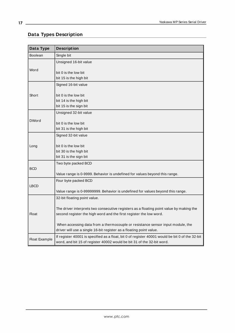
Data Types Descript ion
Data Type Descript ion
Boolean Single bit
Word
Unsigned 16-bit value
bit 0 is the low bit
bit 15 is the high bit
Short
Signed 16-bit value
bit 0 is the low bit
bit 14 is the high bit
bit 15 is the sign bit
DWord
Unsigned 32-bit value
bit 0 is the low bit
bit 31 is the high bit
Long
Signed 32-bit value
bit 0 is the low bit
bit 30 is the high bit
bit 31 is the sign bit
BCD
Two byte packed BCD
Value range is 0-9999. Behavior is undefined for values beyond this range.
LBCD
Four byte packed BCD
Value range is 0-99999999. Behavior is undefined for values beyond this range.
Float
32-bit floating point value.
The driver interprets two consecutive registers as a floating point value by making the
second register the high word and the first register the low word.
When accessing data from a thermocouple or resistance sensor input module, the
driver will use a single 16-bit register as a floating point value.
Float ExampleIf register 40001 is specified as a float, bit 0 of register 40001 would be bit 0 of the 32-bit
word, and bit 15 of register 40002 would be bit 31 of the 32-bit word.
www.ptc.com
17
Yaskawa MP Series Serial Driver
Address Descript ionsAddress specifications vary depending on the model in use. Select a link from the following list to obtain spe-
cific address information for the model of interest.
M P Series
GL Series
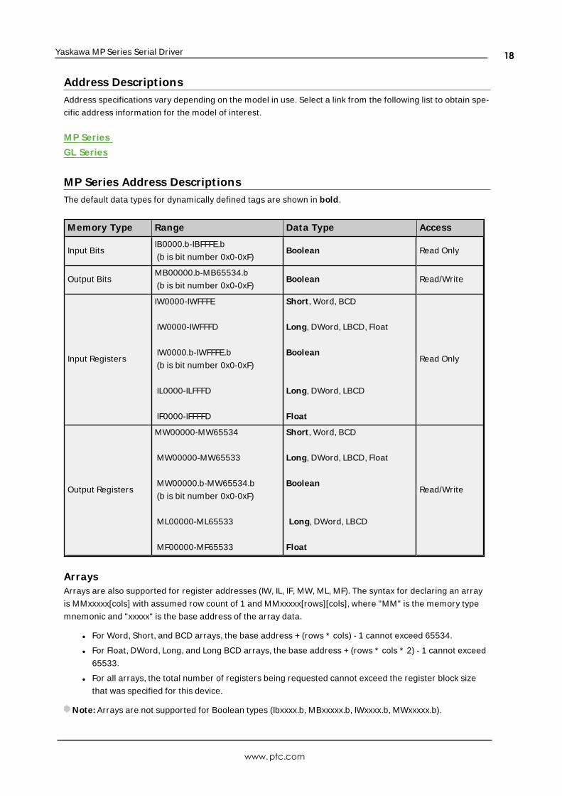
MP Series Address Descript ionsThe default data types for dynamically defined tags are shown in bold.
M emory Type Range Data Type Access
Input BitsIB0000.b-IBFFFE.b
(b is bit number 0x0-0xF)Boolean Read Only
Output BitsMB00000.b-MB65534.b
(b is bit number 0x0-0xF)Boolean Read/Write
Input Registers
IW0000-IWFFFE
IW0000-IWFFFD
IW0000.b-IWFFFE.b
(b is bit number 0x0-0xF)
IL0000-ILFFFD
IF0000-IFFFFD
Short , Word, BCD
Long, DWord, LBCD, Float
Boolean
Long, DWord, LBCD
Float
Read Only
Output Registers
MW00000-MW65534
MW00000-MW65533
MW00000.b-MW65534.b
(b is bit number 0x0-0xF)
ML00000-ML65533
MF00000-MF65533
Short , Word, BCD
Long, DWord, LBCD, Float
Boolean
Long, DWord, LBCD
Float
Read/Write
ArraysArrays are also supported for register addresses (IW, IL, IF, MW, ML, MF). The syntax for declaring an array
is MMxxxxx[cols] with assumed row count of 1 and MMxxxxx[rows][cols], where "MM" is the memory type
mnemonic and "xxxxx" is the base address of the array data.
l For Word, Short, and BCD arrays, the base address + (rows * cols) - 1 cannot exceed 65534.
l For Float, DWord, Long, and Long BCD arrays, the base address + (rows * cols * 2) - 1 cannot exceed
65533.
l For all arrays, the total number of registers being requested cannot exceed the register block size
that was specified for this device.
Note: Arrays are not supported for Boolean types (Ibxxxx.b, MBxxxxx.b, IWxxxx.b, MWxxxxx.b).
www.ptc.com
18

Yaskawa MP Series Serial Driver
Input AddressesInput addresses (IB, IW, IL, IF) are in hex. Bit numbers (b) are always in hex. Array "rows" and "cols" are
always in decimal.
Output AddressesOutput addresses (MB, MW, ML, MF) are in decimal and map to the same memory area. For example,
MB00001.F is the same as MW00001.F. ML00001 and MF00001 both map to the same memory as
MW00001 and MW00002. The same is true for input addresses.
Note: Writes to MB00000-MB04095 are faster than writes to MB04096-MB65534 because they can take
advantage of direct bit access Memobus commands. Writes to the higher bits require the driver to perform
a Read/Modify/Write operation, taking approximately twice as long.
Important: The actual range of valid addresses is hardware specific and may be smaller than the range
allowed by this driver.
GL Series Address Descript ionsThe default data types for dynamically defined tags are shown in bold.
M emory Type Range Data Type Access
Input BitsIB0000.b-IBFFFE.b
(b is bit number 0x0-0xF)Boolean Read Only
Output BitsMB00000.b-MB65534.b
(b is bit number 0x0-0xF)Boolean Read/Write
Input Registers
IW0000-IWFFFE
IW0000-IWFFFD
IW0000.b-IWFFFE.b
(b is bit number 0x0-0xF)
IL0000-ILFFFD
IF0000-IFFFFD
Short , Word, BCD
Long, DWord, LBCD, Float
Boolean
Long, DWord, LBCD
Float
Read Only
Output Registers
MW00000-MW65534
MW00000-MW65533
MW00000.b-MW65534.b
(b is bit number 0x0-0xF)
ML00000-ML65533
MF00000-MF65533
Short , Word, BCD
Long, DWord, LBCD, Float
Boolean
Long, DWord, LBCD
Float
Read/Write
Constant Registers
CW00000-CW65534
CW00000-CW65533
Short, Word, BCD
Long, DWord, LBCD, Float
Read/Write
www.ptc.com
19

Yaskawa MP Series Serial Driver
ArraysArrays are also supported for register addresses (IW, IL, IF, MW, ML, MF, CW). The syntax for declaring an
array is MMxxxxx[cols] with assumed row count of 1 and MMxxxxx[rows][cols], where "MM" is the memory
type mnemonic and "xxxxx" is the base address of the array data.
l For Word, Short, and BCD arrays, the base address + (rows * cols)-1 cannot exceed 65534.
l For Float, DWord, Long, and Long BCD arrays, the base address + (rows * cols * 2)-1 cannot exceed
65533.
l For all arrays, the total number of registers being requested cannot exceed the register block size
that was specified for this device.
Note: Arrays are not supported for Boolean types (Ibxxxx.b, MBxxxxx.b, IWxxxx.b, MWxxxxx.b).
Input AddressesInput addresses (IB, IW, IL, IF) are in hex. Bit numbers (b) are always in hex. Array "rows" and "cols" are
always in decimal.
Output AddressesOutput addresses (MB, MW, ML, MF) are in decimal and map to the same memory area. For example,
MB00001.F is the same as MW00001.F. ML00001 and MF00001 both map to the same memory as
MW00001 and MW00002. The same is true for input addresses.
Note: Writes to MB00000-MB04095 are faster than writes to MB04096-MB65534 because they can take
advantage of direct bit access Memobus commands. Writes to the higher bits require the driver to perform
a Read/Modify/Write operation, taking approximately twice as long.
Important: The actual range of valid addresses is hardware specific and may be smaller than the range
allowed by this driver.
www.ptc.com
20
Yaskawa MP Series Serial Driver
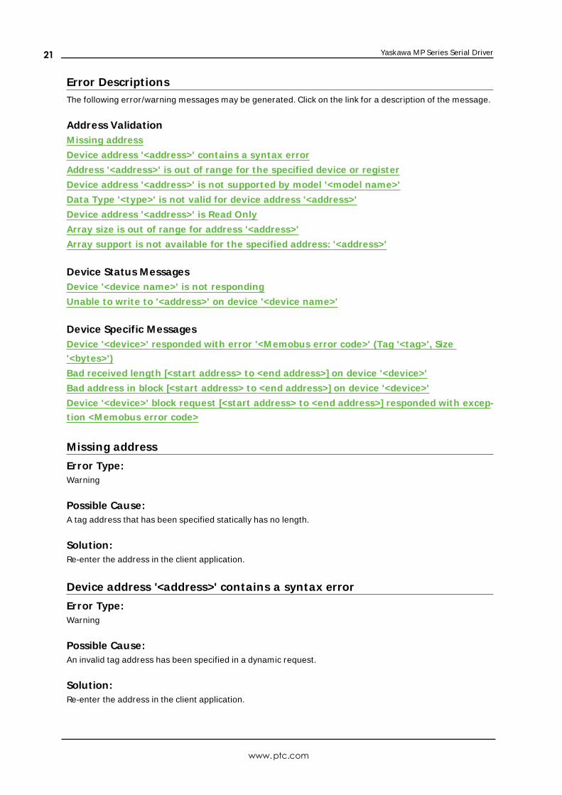
Error Descript ionsThe following error/warning messages may be generated. Click on the link for a description of the message.
Address ValidationM issing address
Device address '<address>' contains a syntax error
Address '<address>' is out of range for the specified device or register
Device address '<address>' is not supported by model '<model name>'
Data Type '<type>' is not valid for device address '<address>'
Device address '<address>' is Read Only
Array size is out of range for address '<address>'
Array support is not available for the specified address: '<address>'
Device Status MessagesDevice '<device name>' is not responding
Unable to write to '<address>' on device '<device name>'
Device Specific MessagesDevice '<device>' responded with error '<M emobus error code>' (Tag '<tag>', Size
'<bytes>')
Bad received length [<start address> to <end address>] on device '<device>'
Bad address in block [<start address> to <end address>] on device '<device>'
Device '<device>' block request [<start address> to <end address>] responded with excep-
t ion <M emobus error code>
Missing address
Error Type:Warning
Possible Cause:A tag address that has been specified statically has no length.
Solution:Re-enter the address in the client application.
Device address '<address>' contains a syntax error
Error Type:Warning
Possible Cause:An invalid tag address has been specified in a dynamic request.
Solution:Re-enter the address in the client application.
www.ptc.com
21
Yaskawa MP Series Serial Driver
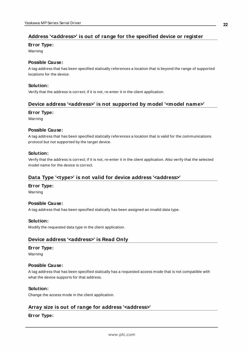
Address '<address>' is out of range for the specified device or register
Error Type:Warning
Possible Cause:A tag address that has been specified statically references a location that is beyond the range of supported
locations for the device.
Solution:Verify that the address is correct; if it is not, re-enter it in the client application.
Device address '<address>' is not supported by model '<model name>'
Error Type:Warning
Possible Cause:A tag address that has been specified statically references a location that is valid for the communications
protocol but not supported by the target device.
Solution:Verify that the address is correct; if it is not, re-enter it in the client application. Also verify that the selected
model name for the device is correct.
Data Type '<type>' is not valid for device address '<address>'
Error Type:Warning
Possible Cause:A tag address that has been specified statically has been assigned an invalid data type.
Solution:Modify the requested data type in the client application.
Device address '<address>' is Read Only
Error Type:Warning
Possible Cause:A tag address that has been specified statically has a requested access mode that is not compatible with
what the device supports for that address.
Solution:Change the access mode in the client application.
Array size is out of range for address '<address>'
Error Type:
www.ptc.com
22
Yaskawa MP Series Serial Driver
Warning
Possible Cause:A tag address that has been specified statically is requesting an array size that is too large for the address
type or block size of the driver.
Solution:Re-enter the address in the client application to specify a smaller value for the array or a different starting
point.
Array support is not available for the specified address: '<address>'
Error Type:Warning
Possible Cause:A tag address that has been specified statically contains an array reference for an address type that doesn't
support arrays.
Solution:Re-enter the address in the client application to remove the array reference or correct the address type.
Device '<device name>' is not responding
Error Type:Serious
Possible Cause:
1. The connection between the device and the Host PC is broken.
2. The communication properties for the connection are incorrect.
3. The named device may have been assigned an incorrect Network ID.
4. The response from the device took longer to receive than the amount of time specified in the
"Request Timeout" device property.
Solution:
1. Verify the cabling between the PC and the device.
2. Verify that the specified communication properties match those of the device.
3. Verify that the Network ID given to the named device matches that of the actual device.
4. Increase the Request Timeout property so that the entire response can be handled.
Unable to write to '<address>' on device '<device name>'
Error Type:Serious
www.ptc.com
23

Yaskawa MP Series Serial Driver
Possible Cause:
1. The named device may not be connected to the network.
2. The named device may have been assigned an incorrect Network ID.
3. The named device is not responding to write requests.
4. The address does not exist in the PLC.
Solution:
1. Check the PLC network connections.
2. Verify that the Network ID given to the named device matches that of the actual device.
Device '<device>' responded with error '<Memobus error code>' (Tag'<tag>', Size '<bytes>')
Error Type:Fatal
Possible Cause:The driver attempted to read a block of memory in the PLC. The PLC responded with the specified Memobus
error code.
Solution:Ensure that the range of memory exists for the PLC.
Bad received length [<start address> to <end address>] on device '<device>'
Error Type:Fatal
Possible Cause:The driver attempted to read a block of memory in the PLC. The PLC responded with no error, but did not
provide the driver with the requested block size of data.
Solution:Ensure that the range of memory exists for the PLC.
Bad address in block [<start address> to <end address>] on device'<device>'
Error Type:Fatal
Possible Cause:The driver attempted to read a location that does not exist in a PLC. For example, this error would be gen-
erated in a PLC that only has input registers IW00000 to IW10000 but requests address IW10001. Once this
error has been generated, the driver will not request the specified block of data from the PLC again. Any
other addresses being requested that are in the same block will also be invalid.
www.ptc.com
24

Yaskawa MP Series Serial Driver
Solution:Ensure that the range of memory exists for the PLC.
Device '<device>' block request [<start address> to <end address>] respon-ded with exception <Memobus error code>
Error Type:Fatal
Possible Cause:The driver attempted to read a location that does not exist in a PLC. For example, this error would be gen-
erated in a PLC that only has input registers IW00000 to IW10000 but requests address IW10001. Once this
error has been generated, the driver will not request the specified block of data from the PLC again. Any
other addresses being requested that are in the same block will also be invalid.
Solution:Ensure that the range of memory exists for the PLC.
www.ptc.com
25

Yaskawa MP Series Serial Driver
Index
A
Address '<address>' is out of range for the specified device or register 22
Address Descriptions 18
Array size is out of range for address '<address>' 22
Array support is not available for the specified address: '<address>' 23
Attempts Before Timeout 15
Auto-Demotion 15
B
Bad address in block [<start address> to <end address>] on device <device> 24
Bad received length [<start address> to <end address>] on device <device> 24
Baud Rate 5
BCD 17
Bits 16
Block Sizes 16
Boolean 17
C
Channel Assignment 12
COM ID 5
Communication Protocol 5
Communications Timeouts 14-15
Connect Timeout 14
Constant Registers 19
D
Data Bits 5
Data Collection 13
Data Type '<type>' is not valid for device address '<address>' 22
Data Types Description 17
Demote on Failure 15
Demotion Period 15
www.ptc.com
26

Yaskawa MP Series Serial Driver
Device '<device name>' is not responding 23
Device <device> block request [<start address> to <end address>] responded with exception <Memobus
error code> 25
Device <device> responded with error <Memobus error code> Tag <tag> Size <bytes> 24
Device address '<address>' contains a syntax error 21
Device address '<address>' is not supported by model '<model name>' 22
Device address '<address>' is Read Only 22
Device ID 5
Discard Requests when Demoted 15
Do Not Scan, Demand Poll Only 14
Driver 12
DWord 17
E
Error Descriptions 21
F
Float 17
Flow Control 5
G
General 12
GL Series Address Descriptions 19
H
hardware 5
Holding Register 18
I
ID 12
Identification 12
Initial Updates from Cache 14
Input bits 16
www.ptc.com
27

Yaskawa MP Series Serial Driver
Inter-Request Delay 15
L
LBCD 17
Long 17
M
Memobus 5
Missing address 21
model 18
Model 12
MP Series Address Descriptions 18
N
Name 12
O
Operating Mode 13
output bits 16
Overview 4
P
Parity 5
R
Redundancy 16
register 17
Registers 16
Request Timeout 5, 14
Respect Tag-Specified Scan Rate 14
Retry Attempts 5
RS232 5
www.ptc.com
28

Yaskawa MP Series Serial Driver
RS485 5
RTS flow 5
S
Scan Mode 13
Setup 5
Short 17
Simulated 13
Stop Bits 5
T
Timeouts to Demote 15
U
Unable to write to '<address>' on device '<device name>' 23
W
Word 17
www.ptc.com
29